

Page 1

JC279ET61S Service Manual
TABLE OF CONTENTS
1. PRECAUTION AND NOTICES------------------------------------------ -- - ---- - ----------------------------------- 1
1.1. SAFETY PRECAUTIONS ----------------------------------------------------------------------------------------1
1.2. PRODUCT SAFETY NOTICE ------------------------------------------------------------------------ --- ---- - --- 1
1.3. SERVICE NOTES--------------------------------------------------------------------------------------------------1
SERVICE TOOL & EQUIPMENT REQUIRED
2.
3. SPECIFICATIONS----------------------------------------------------------------------------------------------------- 2~4
PRODUCT SPECIFICATIONS
3.1.
FACTORY SUPPORTING MODES
3.2.
3.3. D-SUB CONNECTOR --------------------------------------------------------------------------------------------4
3.4. HDMI CONNECTOR ---------------------------------------------------------------------------------------------4
4. EXPLODED VIEW AND PARTS LIST ------- - --- -- --- -- - ---- - --------------------------------------------------- 5~6
4.1. EXPLODED VIEW------------------------------------------------------------------------------------------------ 5
4.2. EXPLODED VIEW PARTS LIST--------------------------------------------------------------------------------6
5. BLOCK DIAGRAM----------------------------------------------------------------------------------------------------7
6. SCHEMATIC DIAGRAM --------------------------------------------------------------------------------------------8~18
6.1. Power----------------------------------------------------------------------------------------------------------------8
6.2. HDMI Interface---------------------------------------------------------------------------------------------------- 9
6.3. VGA Interface------------------------------------------------------------------------------------------------------ 10
6.4. Video & USB Interface--------------------------------------------------------------------------------------------11
6.5. Tuner Interface-----------------------------------------------------------------------------------------------------12
6.6. Audio Interface-----------------------------------------------------------------------------------------------------13
6.7. Audio AMP.---------------------------------------------------------------------------------------------------------14
6.8. DDR -----------------------------------------------------------------------------------------------------------------15
6.9. SCALER MST9B884JL -------------------------------------------------------------------------------------------16
6.10. Panel Interface----------------------------------------------------------------------------------------------------- 17
6.11. DTV Module Interface --------------------------------------------------------------------------------------------18
7. WORKING THEOREM----------------------------------------------------------------------------------------------- 19~21
8. WIRING DIAGRAM---------------------------------------------------------------------------------------------------22
9. PCB LAYOUT-----------------------------------------------------------------------------------------------------------23~30
9.1. MAIN PCB TOP VIEW -------------------------------------------------------------------------------------------23
9.2. MAIN PCB BOTTOM VIEW-------------------------------------------------------------------------------------24
9.3. KEYPAD PCB TOP VIEW ---------------------------------------------------------------------------------------25
9.4. KEYPAD PCB BOTTOM VIEW---------------------------------------------------------------------------------26
9.5. IR PCB TOP VIEW------------------------------------------------------------------------------------------------ 27
9.6. IR PCB BOTTOM VIEW ----------------------------------------------------------------------------------------- 28
9.7. POWER PCB TOP VIEW ---------------------------------------------------------------------------------------- 29
9.8. POWER PCB BOTTOM VIEW----------------------------------------------------------------------------------30
10. TROUBLE SHOOTING FLOW CHART-------------------------------------------------------------------------31~34
NO POWER
10.1.
NO VOICE
10.2.
NO DISPLAY
10.3.
11. ADJUSTMENT----------------------------------------------------------------------------------------------------------35~37
11.1. ADJUSTMENT CONDITIONS AND PRECAUTIONS- ------------------------------------------------------35
11.2. MAIN ADJUSTMENTS ------------------------------------------------------------------------------------------- 35
11.3. ALIGNMENT PROCEDURES----------------------------------------------------------------------------------- 35~37
--------------------------------------------------------------------------------------------------------31
----------------------------------------------------------------------------------------------------------32
-------------------------------------------------------------------------------------------------------33~34
-----------------------------------------------------------------------------2
------------------------------------------------------------------------ 3
---------------------------------------------------------2
PAGE
05/12/2010
Page 2

JC279ET61S Service Manual
1. PRECAUTION AND NOTICES
1.1. SAFETY PRECAUTIONS
This monitor is manufactured and tested on a ground principle that a user's safety comes
first.However, improper use or installation may cause damage to the monitor as well as to
the user.Carefully go over the following WARNINGS before installing and keep this guide
handy.
WARNINGS:
This monitor should be operated only at the correct power sources indicated on the label
on the rear end of the monitor. If you're unsure of the power supply in your residence,
consult your local dealer or power company.
Use only the special power adapter that comes with this monitor for power input.
Do not try to repair the monitor your self as it contains no user-serviceable parts. This
monitor should only be repaired by a qualified technician.
Do not remove the monitor cabinet. There is high-voltage parts inside that may cause
electric shock to human bodies, even when the power cord is unplugged.
Stop using the monitor if the cabinet is damaged. Have it checked by a service technacian.
Put your monitor only in a clean, dry environment. If it gets wet, unplug the power cable
immediately and consult your service technician.
Always unplug the monitor before cleaning it. Clean the cabinet with a clean, dry cloth.
Apply non-ammonia based cleaner onto the cloth, not directly onto the glass screen.
Keep the monitor away from magnetic objects, motors, TV sets, and transformer.
Do not place heavy objects on the monitor or power cord.
1.2. PRODUCT SAFETY NOTICE
Many electrical and mechanical parts in this chassis have special safety visual inspections
and theprotection afforded by them cannot necessarily be obtained by using replacement
components rated for higher voltages, wattage, etc. Before replacing any of these
components read the parts list in this manual carefully. The use of substitute replacement
parts which do not have the same safety characteristics as specified in the parts list may
create shock, fire, or other hazards.
1.3. SERVICE NOTES
1. When replacing parts or circuit boards, clamp the lead wires around terminals beforesoldering.
2. When replacing a high wattage resistor (more than 1W of metal oxide film resistor) in circuit
board, keep the resistor about 5mm away from circuit board.
3. Keep wires away from high voltage, high temperature components and sharp edges.
4. Keep wires in their original position so as to reduce interference.
5. Usage of this product please refer to also user's manual.
-1-
05/12/2010
Page 3

JC279ET61S Service Manual
2. SERVICE TOOL & EQUIPMENT REQUIRED
1. SIGNAL GEN.
2. MULTIMETER
3. OSCILLOSCOPE
4. SCREW DRIVER
5. IRON
6. ABSORBER
7. SOLDER
8. DUMMY LOAD (5ohm/200W)
3. SPECIFICATIONS
3.1. PRODUCT SPECIFICATIONS
LCD Panel 27.0" TFT
Power Management Energy Star compliant VESA
DPMS compatible
< 1W
Displayable Resolution 1920*1080 (max.)
Pixel Pitch 0.3114 (H) × 0.3114 (W)mm
LCD Display Color 16.7M Color Max.
Viewing Angle CR ≥ 10
Horizontal: 170°
Vertical: 160°
Tilt 0+1/-4 degree to 20 +2/-2 degree
Contrast Ratio 1200 : 1 (typ.)/800:1(MIN)
Brightness 300 cd/㎡(typical) 250 cd/㎡(mini)
Response Time Tr:+Tf: 3.4ms(typ.)
Active Display Area
Temperature Operating: 0°C ~ +40°C
Storage: -20°C ~ +60°C
Compliance VESA DDC1/2B Revision 1.3
Power Input Voltage: 90~264 Vac
Consumption: 80 Watts (Max.)
597.89 (H) x 336.31 (V) mm
-2-
05/12/2010
Page 4
JC279ET61S Service Manual
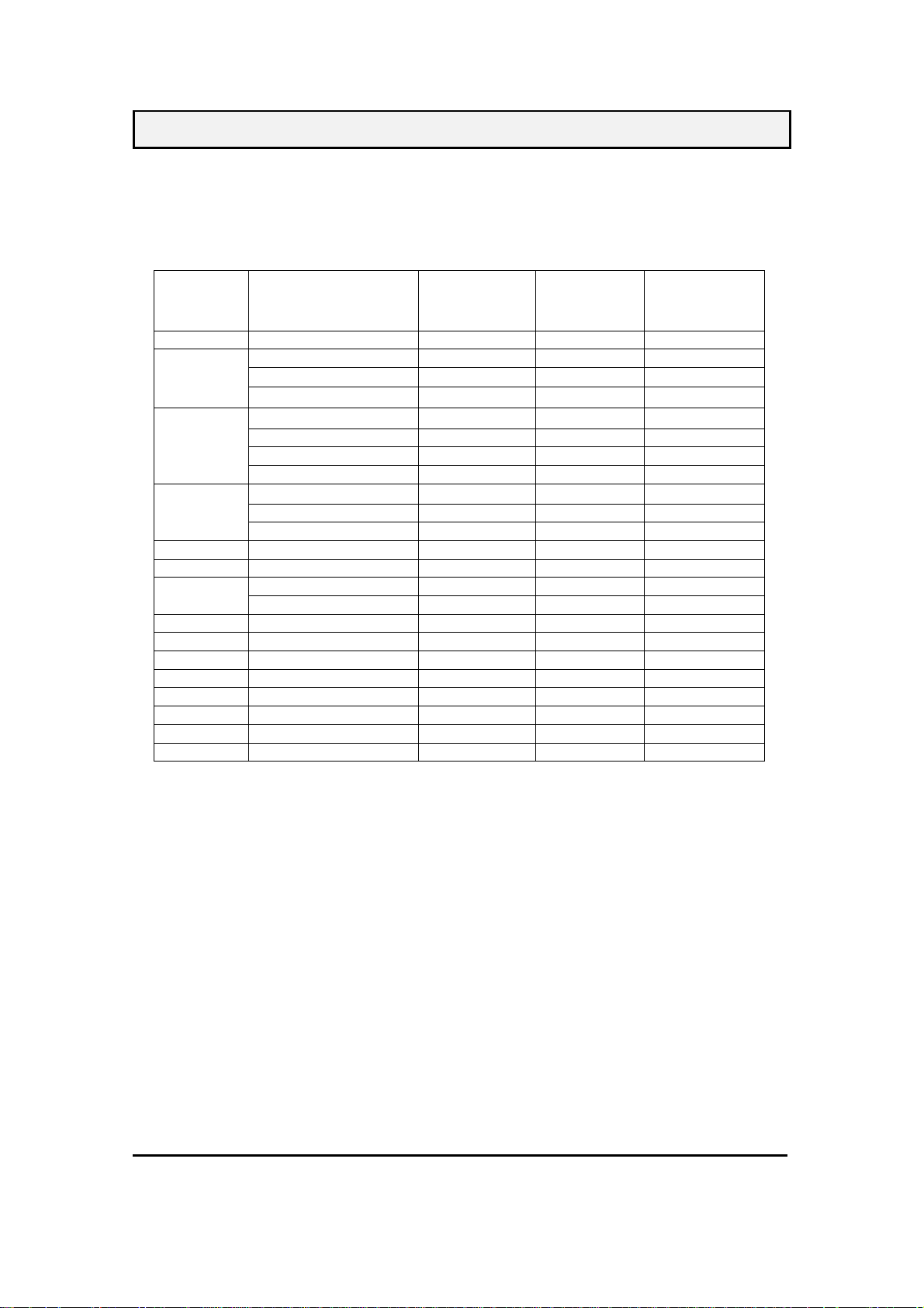
3.2. FACTORY SUPPORTING MODES
There are totally timings mode that can be saved in memory by FIFO architecture.
This monitor can support VGA up to WUXGA+ resolution.
Resolution
Mode
IBM, VGA 720x400@70Hz 31.469 70.080 28.320
VGA
SVGA
XGA
XGA+ 1152x864@75Hz 67.500 75.000 108.000
WXGA 1280x960@60Hz 60.000 60.000 108.000
1400x1050@60Hz 65.317 59.978 121.750
WXGA 1280x960@60Hz 60.000 60.000 108.000
WXGA+ 1440x900@60Hz 55.935 59.887 106.500
WSXGA+ 1680x1050@60Hz 65.290 59.954 146.250
FHD 1920x1080@60Hz 67.500 60.000 148.500
MAC 640x480@67Hz 35.000 66.667 30.240
MAC 832x624@75Hz 49.725 74.550 57.283
MAC 1152x870@75Hz 68.681 75.062 100.000
Plus
Frequency
640x480@60 Hz 31.469 59.940 25.175
640x480@72 Hz 37.861 72.809 31.500
640x480@75 Hz 37.500 75.000 31.500
800x600@56Hz 35.156 56.250 36.000
800x600@60Hz 37.879 60.317 40.000
800x600@72Hz 48.077 72.188 50.000
800x600@75Hz 46.875 75.000 49.500
1024x768@60Hz 48.363 60.004 65.000
1024x768@70Hz 56.476 70.069 75.000
1024x768@75Hz 60.023 75.029 78.750
1280x1024@60Hz 63.981 60.020 108.000 SXGA
1280x1024@75Hz 79.976 75.025 135.000
Horizontal
Frequency
(kHz)
Vertical
Frequency
(Hz)
Pixel
Frequency
(MHz)
-3-
05/12/2010
Page 5

JC279ET61S Service Manual
3.3.
D-SUB CONNECTOR
D-SUB 15 PIN CONNECTOR
12345
678910
11 12 13 14 15
CONNECTOR SIGNAL DESCRIPTION
3.4.
HDMI CONNECTOR
19 pins HDMI connector is designed to match with HDMI digital signal cable, the pin
assignment is as the following:
1.R 6.GND 11.NC
2.G 7.GND 12.SDA
3.B 8.GND 13.H.SYNC
4.NC 9. +5V 14.V.SYNC
R RED 0.7vp-p(VIDEO)
G GREEN 0.7vp-p(VIDEO)
B BLUE 0.7vp-p(VIDEO)
H H/SYNC TTL positive or negative
V V/SYNC TTL positive or negative
SDA DDC1/2B TTL
SCL DDC1/2B TTL
5.GND 10.GND 15.SCL
Pin 19
Pin 18
Pin S ignal Assignment Pin Signal Assignment
1 TMDS RX2+ 11 TMDS Ground
2 TMDS Ground 12 TMDS Clock3 TMDS RX2- 13 CEC
4 TMDS RX1+ 14 Floating
5 TMDS Ground 15 DDC Clock
6 TMDS RX1- 16 DDC Data
7 TMDS RX0+ 17 Ground
8 TMDS Ground 18 +5V Power
9 TMDS RX0- 19 Hot Plug Detect
10 TMDS Clock+
*19 pins HDMI female
Pin 1
Pin 2
-4-
05/12/2010
Page 6

4.1. EXPLODED VIEW
JC279ET61S Service Manual
-5-
05/12/2010
Page 7

JC279ET61S Service Manual
4.2. EXPLODED VIEW PARTS LIST
Ref. No. Source Part No. DESCRIPTION SPECIFICATION Q‘TY REMARK
1F01
1F02 2033154601P IR COVER JC279E PC LIMPID GE121R-21051 1
1F03 2053761401P LED INDIC.-PWR JC279E LENS PMMA 94HB 1
1F05 2044275801P FUNCTION KEY JC279E ABS94HB G.L BLACK 1
2C01
2C02 2054259801P ORNAMENT
2C03 2084730062P SCREW BND T+ M3X6(BND T+) 5
5B01 2028268601P STAND
5B02 2028562601P NECK JC279U ABS94HB G.L BLACK 1
5B03 2106665900P HINGE
5B04 2086240142P SCREW P SW+ M4*14mm PSW+2N 4
5B05 2039820800P FOOT PAD
5F01 2071685404P SHIELD PLATE JC279E 61S SECC 0.6T 1
5F02 2072055904P METAL FITTG-I/O JC279E 61S SIDE IO SECC 0.6T 1
5F03 2054155804P ORNAMENT
5F04 2080003700P SCREW SPE ISZZTER001A M3*6L MSWR17/FZMYI 4
5F05 2080003700P SCREW SPE ISZZTER001A M3*6L MSWR17/FZMYI 2
5F06 2082630082P SCREW M3X8 P=0.5 2
5F08 2084730084P SCREW BND T+ M3X8(BND T+) (BLK) 1
5F11 2082630084P SCREW M3X8 P=0.5 BLACK 1
5F12 2082630084P SCREW M3X8 P=0.5 BLACK 1
6B01 2084730084P SCREW BND T+ M3X8(BND T+) (BLK) 1
6B02 2084740084P SCREW BND T+
6B03 2086240142P SCREW P SW+ M4*14mm PSW+2N 4
6B04 2027276001P DUST COVER
6F01 2084730082P SCREW BND T+ M3X8(BND T+) 1
6F02 2071898500P BRACKET FIX JC279E HINGE SUPPORT SECC 1.0T 2
6F03 2082630062P SCREW M3X6 P=0.5 2
6F04 2084740082P SCREW BND T+ M4X8(BND T+) 2
2024291101P
-05
2022288604P
-01
FRONT BEZEL
CABI BACK JC279E S ABS94HB G.L BLACK 1
JC279E ENVISION ABS94HB G.L
BLACK
JC279E BOTTOM DECO PLATE
TRANSPARANGE PC
JT269 T STAND ABS 94HB G.L
BLACK
JC279E U NECK HINGE 0~20° 50kg
-CM (H.Y.)
φ20*3.0T SQUARE GRAIN BLK
JC279E 61S SIDE IO PC 0.5T
ADHESIVE BLACK
SCREW BNDT+ M4*8(BND T+)
BLACK
JC279E HINGE COVER ABS94HB G. L
BLACK
1
1
1
1
4
1
2
1
-6-
05/12/2010
Page 8

5. BLOCK DIAGRAM
JC279ET61S Service Manual
5
D D
I111
TUNER
I112
I113
SAW FILTER
4
3
2
1
LCD Module
HDCP & System
P102
HDMI 19P
P103
C C
HDMI 19P
P104
HDMI 19P
I108
IT6633T
HDMI Switch
I116
EEPROM
I118
Flash
I114 DDR
128Mb_TSOP66
MST9B884JL-LF-3-S1
AV(CVBS)
S-Video
YPbPR
I601
TPA3113D2
I603
TPA6113A2
Speaker
P111
Headphone
B B
PC (VGA)
I604
APA4880KI
P603
RCA Audio out
AV / SV Audio (R/L)
YPbPR Audio (R/L)
PC / DVI Audio (R/L)
A A
5
4
3
2
P108
USB
JEAN
JEAN
Title
Title
Title
Size Document Number Rev
Size Document Number Rev
Size Document Number Rev
B
B
B
Date: Sheet
Date: Sheet
Date: Sheet
JE240xx61S_JE279xx61S
JE240xx61S_JE279xx61S
JE240xx61S_JE279xx61S
JEAN
BLOCK
BLOCK
BLOCK
of
111Monday, May 03, 2010
of
111Monday, May 03, 2010
of
111Monday, May 03, 2010
1
1.0
1.0
1.0
-7-
05/12/2010
Page 9

6. SCHEMATIC DIAGRAM
6.1. Power
JC279ET61S Service Manual
P101
1
2
3
4
5
6
7
8
9
PH_12H_Power
10
11
12
TU_12V5
P120
1
2
3
4
NC/PH_4H_DTV_Power
R101 0R
P1D
DDIMM Dimming
B_O_F BL_EN
5V_POWER
1GND
12V_POWER
32
Q116
NC/2N3904
TU_12V
POWER_EN
C104
100nF
R369 NC/22K
R372 NC
R367 NC/22K
1
TU_12V
DCR_EN
L103 80_3.5X6X2
C109
100nF
C243
100nF
C101
100nF
I122
AP9435GM
L101
80_3.5X6X2
+
C107
470uF_16V_LESR
PW_CTL
18
SD
27
SD
36
SD
45
GD
R434 47K
+5V_STB
C102
470uF_16V_LESR
+12V
+5V_STB
C241
NC
R433
0R
+12V
1
+
+12V
+5V_STB
+12V 7
R432
22K
32
Q117
2N3904
C103
100nF
+5V_STB 2,3,9
+5V_STB
BL_EN
L106
120R_0603_3A
100uF_16V
24" LED= Hi: OFF,Lo: ON
Q101
NC
32
R102 NC
R107 0R
R106
100R
1.3V Core Power
VCC5V_IN
C114
+
C113
100nF
C121
100nF
R113 NC
1
C106
NC/100nF
R119
100K
+3.3V for
AVDD_MemPLL
+5V_STB
R118
R108
NC
3.3K
VCC5V_OCSET
C116
100nF
RB
+3.3_STB
R109
NC
VCC5V_EN
ON-PBACK
VCC1.2V_FB
1.5K_1%_0603
+3.3V for
AVDD_AU
I102
AP1534
4 5
VCC OUTPUT
3
OCSET
OUTPUT
2
EN
VSS
1
FB
VSS
R121 1K_1%_0603
R123
AVDD_AU
RA
0 ~ 3V3
Dimming
C105
NC/10uF_10V
6
7
8
R110
0R
R114
NC
L107
22uH-SMD
VCC1.2V_OUT
D101
SR34
220uF_16V_LESR
Vout=VFB*(1+RA/RB)
VFB=0.8V
RB=0.7K~5Kohm
+3.3V for
AVDD_USB2
C111
R105 10K
32
C112
+
1uF_16V
R111 100R
1
Q102
NC/2N3904
VCC1.26V
+3.3V for
AVDDA
R115
NC/4.7K
C115
100nF
AVDDAAVDD_MemPLL AVDD_USB2
+5V_STB
ADJ_PWM
DCR_EN
Code Power
+1.2V for VDDC
C16210uF_10V
C163100nF
+3.3V_STB for
VDDP
+5V_STB
R103
10K
C164100nF
Q103
NC
32
C165100nF
+3.3_STB
R104
NC
1
R116
NC
C166100nF
R112
100R
DCR_CTL
C108
NC
ON-PBACK
ADJ_PWM
VDDCVCC1.26V
C167100nF
VDDP+3.3_STB
DCR_CTL 9
ON-PBACK 9
ADJ_PWM 9
AVDD_VIF5
AVDD_VIF2
AVDD_VIF1
AVDD_AU
AVDDA
VDDM
VDDC
VDDP
AVDD_MPLL
AVDD_MemPLL
AVDD_USB2
AVDD_VIF5 9
AVDD_VIF2 9
AVDD_VIF1 9
AVDD_AU 2,9,10,11
AVDDA 2,9,10,11
VDDM 8,9
VDDC 9
VDDP 2,9,10,11
AVDD_MPLL 9
AVDD_MemPLL 2,9,10,11
AVDD_USB2 2,9,10,11
3.3V Stand-by Power
+5V_STB
C11722uF_10V
C119100nF
VCC3.3V_ADJ
+12V
+5V_STB
ON-PANEL
ON-PANEL9
PW_CTL
Hi = Off
Lo = On
PW_CTL POWER_EN
PW_CTL7,9
I101 1084-33
VOUTVIN
1
ADJ
TAB
R120 NC
R122 0R
L113 NC/120R_0805_6A
L114
120R_0805_6A
R131
NC
R135
22K
Q106
2N3904
+5V_STB
23
4
32
1
R133 NC
R136 22K
+3.3_STB
C120
100nF
R127
22K
D143 1N4148
32
1
R130 22K
+3.3_STB
R126
22K
R129
100K
Q104
2N3904
2N3904
Q107
+3.3_STB 2,9,10,11
+
C118
220uF_16V_LESR
C160
C170
220nF_16V
100uF_16V
32
1
+
R134 22K
+5V_STB
measure current
R128
22K
R132
0R
470uF_16V_LESR
32
Q105
1
2N3904
C161
NC
1
2
3
4
C168
+3.3_STB
I104
STM4953
S2
G2
S1
G1
C134
10uF_10V
120R_0603_3A
D2
D2
D1
D1
+5V
+
+3.3V for
AVDD_VIF1
L109
C143
10uF_10V
8
7
6
5
measure current
C169
100nF
C135
100nF
C154100pF
C153100nF
VPANEL 10
VPANEL
+5V
+5V 2,4,6,7,9
C136
100nF
C137
100nF
C138
100nF
AVDD_VIF5AVDD_VIF1
100nF
C140
100nF
+3.3_STB
120R_0603_3A
C139
Memory Power Supply
+5V
C14122uF_10V
I103 1084-ADJ
1
ADJ
C142
VCC2.5V_ADJ
100nF
R125 110R_1%_0603
R2
Vout=Vref*(1+R2/R1)+Iadj*R2
Vref=1.25V
+3.3V for
AVDD_VIF2
L110
C144
10uF_10V
VOUTVIN
TAB
R1
R124
100R_1%_0603
C124
100nF
23
4
C125
100nF
C155100nF
C126
100nF
AVDD_VIF2
+2.6MVDD
+
C122
220uF_16V_LESR
+2.6MVDD
C127
100nF
120R_0603_3A
C123
100nF
C129
C128
100nF
100nF
+3.3V for
AVDD_MPLL
L112
C157
10uF_10V
C130
100nF
C131
100nF
AVDD_MPLL+3.3_STBAVDD_VIF1
C158100nF
C132
100nF
C159100nF
C133
100nF
P109
SIP4
Shieding Cover
123
4
1
1
1
1
1
1
1
1
1
1
-8-
05/12/2010
Page 10

6.2. HDMI Interface
JC279ET61S Service Manual
HDMI Connector S1
P103
HDMI 19P
SHIELD
SHIELD
CEC/DDC GND
DDC SCL
DDC SDA
SHIELD
Dat2 shield
Dat1 shield
Dat0 shield
clk shield
DAT0+
DAT0-
DAT1+
DAT1-
DAT2+
DAT2-
CEC
HPD
+5V
clk+
clk-
HDMIS1-5V
D103
20
21
18
17
HDMIS-1-SCL
15
HDMIS-1-SDA
16
HDMIS1_CEC
13
HDMIS1-HPDIN
19
22
2
5
8
11
HDMIS1_RX0P
7
HDMIS1_RX0N
9
HDMIS1_RX1P
4
HDMIS1_RX1N
6
HDMIS1_RX2P
1
HDMIS1_RX2N
3
HDMIS1_CLKP
10
HDMIS1_CLKN
12
NC/1N4148
D109NC
R138
NC/4.7K
D112NC
D111NC
D110NC
TP2
R141
NC/100K
R144 0R
R147 0R R146 0R
R150 0R
R153 0R
R156 0R
R159 0R
R162 0R
R165 0R
HDMIS1-RX0P
HDMIS1-RX0N
HDMIS1-RX1P
HDMIS1-RX1N
HDMIS1-RX2P
HDMIS1-RX2N
HDMIS1-CLKP
HDMIS1-CLKN
DDC EEPROM S1 DDC EEPROM S3
21
3
D118
BAT54C
I106
24C02
1
NC
VCC
2
NC
WP
3
NC
SCL
4 5
GND SDA
8
7
6
HDMIS1_SCL
HDMIS1_SDA
HDMIS1-SCL
HDMIS1-SDA
C173
100nF
R170
22K
HDMIS-WP
R177 100R
R180 100R
R183 100R
R187 100R
HDMIS-1-SCL
HDMIS-1-SDA
R171
47K
R172
47K
HDMI Connector S3
P102
HDMI 19P
SHIELD
SHIELD
CEC/DDC GND
DDC SCL
DDC SDA
CEC
HPD
SHIELD
Dat2 shield
Dat1 shield
Dat0 shield
clk shield
DAT0+
DAT0-
DAT1+
DAT1-
DAT2+
DAT2-
+5V
clk+
clk-
HDMIS3-5V
HDMIS-3-SCL
HDMIS-3-SDA
HDMIS3_CEC
HDMIS3-HPDIN
HDMIS3_RX0P
HDMIS3_RX0N
HDMSI3_RX1P
HDMIS3_RX1N
HDMIS3_RX2P
HDMIS3_RX2N
HDMIS3_CLKP
HDMIS3_CLKN
D102
NC/1N4148
20
21
18
17
15
16
13
19
22
2
5
8
11
7
9
4
6
1
3
10
12
R137
NC/4.7K
D105NC
D106NC
D107NC
D108NC
TP1
R140
NC/100K
R143 0R
R149 0R
R152 0R
R155 0R
R158 0R
R161 0R
R164 0R
HDMIS3-RX0P
HDMIS3-RX0N
HDMIS3-RX1P
HDMIS3-RX1N
HDMIS3-RX2P
HDMIS3-RX2N
HDMIS3-CLKP
HDMIS3-CLKN
DDC EEPROM S2
+5V_STB+5V_STB +5V_STB
HDMIS2-5V
1
2
3
4 5
21
D119
BAT54C
I107
24C02
NC
NC
NC
GND SDA
VCC
SCL
HDMIS2_VCC
3
HDMIS-2-SCL
R174
47K
R175
47K
C174
R173
100nF
22K
8
7
WP
6
HDMIS-WP
HDMIS2_SCL
HDMIS2_SDA HDMIS-2-SDA
R178 100R
R181 100R
R185 100R
R188 100R
HDMI Connector S2
P104
HDMI 19P
CEC/DDC GND
DDC SCL
DDC SDA
Dat2 shield
Dat1 shield
Dat0 shield
clk shield
HDMIS3-5VHDMIS1-5V
1
2
3
4 5
SHIELD
SHIELD
+5V
CEC
HPD
SHIELD
DAT0+
DAT0-
DAT1+
DAT1-
DAT2+
DAT2-
clk+
clk-
D117
BAT54C
I105
24C02
NC
NC
NC
GND SDA
HDMIS2-5V
20
21
18
17
15
16
13
19
22
2
5
8
11
7
9
4
6
1
3
10
12
21
3
8
VCC
7
WP
6
SCL
Q108
2N3904
D104
R139
NC/1N4148
NC/4.7K
HDMIS-2-SCL
HDMIS-2-SDA
HDMIS2_CEC
HDMIS2-HPDIN
HDMIS2_RX0P
HDMIS2_RX0N
HDMIS2_RX1P
HDMIS2_RX1N
HDMIS2_RX2P
HDMIS2_RX2N
HDMIS2_CLKP
HDMIS2_CLKN
D115NC
D114NC
HDMIS-WP
D116NC
R176 100R
R179 100R
HDMIS3-SCLHDMIS2-SCL
HDMIS3-SDAHDMIS2-SDA
R190 2.2K
D113NC
HDMIS3_VCCHDMIS1_VCC
R167
C172
22K
100nF
HDMIS3_SCL
HDMIS3_SDA HDMIS-3-SDA
R184 NC
1
R189
2 3
22K
TP3
R142
NC/100K
R145 0R
R148 0R
R151 0R
R154 0R
R157 0R
R160 0R
R163 0R
R166 0R
HDMIS-3-SCL
R182 100R
R186 100R
HDMIS2-RX0P
HDMIS2-RX0N
HDMIS2-RX1P
HDMIS2-RX1N
HDMIS2-RX2P
HDMIS2-RX2N
HDMIS2-CLKP
HDMIS2-CLKN
R168
47K
3V3_HDMI
WP_EE_B 3,9
R169
47K
+5V_STB
HDMIS2-SDA
HDMIS2-SCL
HDMIS2-CLKN
HDMIS2-CLKP
HDMIS2-RX0N
HDMIS2-RX0P
HDMIS2-RX1N
HDMIS2-RX1P
HDMIS2-RX2N
HDMIS2-RX2P
CONTROL PINS
S1
H
H
S2 HPD1
H
L
LL
LH
L115
120R_0603_3A
C175
1uF_16V
HPDS2
33V_HDMI
33V_HDMI
HPDS3
49
PWBD
50
HPD2
51
SDA2
52
SCL2
53
B21
54
A21
55
VCC
56
B22
57
A22
58
GND
59
B23
60
A23
61
VCC
62
B24
63
A24
64
HPD3
I/O SELECTED
Y / Z
A1/B1
A2/B2
HDMIS1-RX2N
HDMIS1-RX0N
HDMIS1-RX1N
HDMIS1-RX1P
HDMIS1-RX0P
HDMIS1-RX2P
33V_HDMI
48
B14
A14
HDMIS1-CLKP
33V_HDMI
B12
A12
B13
A13
VCC
VCC
GND
I108
IT6633T
SDA3
SCL3
GND
B31
A31
VCC
B32
A32
123456789101112131415
HDMIS3-SDA
HDMIS3-SCL
GND
33V_HDMI
HDMIS3-RX0N
HDMIS3-RX1N
HDMIS3-CLKN
HDMIS3-RX0P
HDMIS3-CLKP
SCL_SINK
SDA_SINK
SCL1
SDA1
SCL2
SDA2
SCL3
SDA3A3/B3
pulled highdiscoonnected
R191 4.7K
R192
NC
GND
VCC
GND
VCC
R19310K
32
S1
31
30
29
28
27
Z1
26
Y1
25
24
Z2
23
Y2
22
21
Z3
20
Y3
19
18
Z4
17
Y4
HPDS1
HDMIS1-SDA
HDMIS1-CLKN
HDMIS1-SCL
333435363738394041424344454647
S2
B11
A11
SCL1
SDA1
HPD1
I2CSEL
HPD_SINK
SDA_SINK
SCL_SINK
B33
A33
VCC
B34
A34
GND
EQ
16
R344 4.7K
R216 NC
33V_HDMI
HDMIS3-RX2N
HDMIS3-RX1P
HDMIS3-RX2P
HOT PLUG DETECT STATUS
HPD2
HPD_SINK
L
HPD_SINK
L
HPD_SINK
HPD_SINK
L
L
33V_HDMI
R19410K
TXCLK2TXCLK2+
B_2TX0B_2TX0+
G_2TX1G_2TX1+
R_2TX2R_2TX2+
33V_HDMI
R3464.7K
R3474.7K
R208 22R
R209 22R
33V_HDMI
33V_HDMI
R199 100R
R198 100R
R206
4.7K
R207
4.7K
TXCLK2- 9
TXCLK2+ 9
B_2TX0- 9
B_2TX0+ 9
G_2TX1- 9
G_2TX1+ 9
R_2TX2- 9
R_2TX2+ 9
HPD3
L
L
HPD_SINK
HPD_SINK
33V_HDMI
SDA_HD2
SCL_HD2
HDMIS2_SEL 9
HDMIS1_SEL 9
HPLUGB 9
SDA_HD2 9
SCL_HD2 9
3V3_HDMI
120R_0805_6A
L116
HDMIS1-HPDIN
R201
100K
33V_HDMI
C17122uF_10V
33V_HDMI
C180100nF
2 3
C17622uF_10V
C181100nF
Q110
2N3904
R196 1K
R204
10K
1
C177100nF
C182100nF
C183100nF
C178100nF
HDMIS1-5V
HPDS1
C184100nF
Hot-Plug Control 2
HDMIS2-HPDIN
C179100nF
C185100nF
C186100nF
R202
100K
R197 1K
1
Q111
2 3
2N3904
HDMIS1_CEC
HDMIS2_CEC
HDMIS3_CEC
Hot-Plug Control 3Hot-Plug Control 1
HDMIS2-5V HDMIS3-5V
R205
10K
HPDS2
R210 NC/0R
R212 NC/0R
R213 NC/0R
HDMIS3-HPDIN
NC/2N7002
R200
100K
Q109
2 3
2N3904
Q112
R214 0R
R195 1K
1
HDMI 3.3V Power
+5V
+5V1,4,6,7,9
C18722uF_10V
C190100nF
1
I109
1117-33
ADJ
R217 NC
R218 0R
VOUTVIN
TAB
R203
10K
R211 NC
R215 100R
23
4
C189
100nF
HPDS3
+3.3_STB
To MST IC
HDMI_CEC
3V3_HDMI
+
C188
220uF_16V_LESR
HDMI_CEC 9
-9-
05/12/2010
Page 11

6.3. VGA Interface
JC279ET61S Service Manual
D120
4.7P
VGA_TX
VGA_VSYNC
D126
VGA_HSYNC
4.7P
P105
DSUB-15
11
12
13
14
15
R226 100R
R227 100R
D127
4.7P
Note:Close to MST. IC
1
6
2
7
3
8
VGA_RX
4
VGA5V
9
5
1016
17
D121
4.7P
D122
4.7P
D123
4.7P
D124
4.7P
R229 470R
D125
4.7P
R
G
B
R224
R223
75R 1%
75R 1%
RGB-
R228 2.2K
HS_RGB
R225
75R 1%
R219 47R
R220 47R
R221 47R
R222 470R
C191 47nF
C192 47nF
C193 47nF
C194 1nF
HS_RGB 9
RIN+
GIN+
BIN+
SOG
RIN+ 9
GIN+ 9
BIN+ 9
SOG 9
D128
4.7P
+5V_STB1,2,9
D129
4.7P
+5V_STB
VGA5V
21
D130
BAT54C
R230 470R
VGA_PW
0R
R233
22K
R238
0R
R232
22K
DDC_SCL
DDC_SDA
R237
R240
10K
VCC
WP
SCL
+5V_STB
8
7
6
3
C195
100nF
I110
24C02
1
NC
2
NC
3
NC
4 5
GND SDA
VS_RGB
R231 10K
VGA_TX
VGA_RX
Q113
2N3904
2 3
R234 NC
R235 NC
R236 100R
R239 100R
R242 NC
R243
22K
1
RXD
TXD
R241 NC
WP_EE_B
VS_RGB 9
RXD 9
TXD 9
WP_EE_B 2,9
-10-
05/12/2010
Page 12

6.4. Video & USB Interface
P106
RCA1X5_YPbPr
1
3
5
7
9
P107
RCA1X3_AV+S
1
4
6
14
12
9
10
Y Pb Pr Input
Y_IN
2
Pr_IN
Pb_IN
4
Pr_IN
6
AUL_COMP
8
AUR_COMP
10
AUR_AV
3
5
Y_IN
Pb_IN
AV Input
CVBS_IN
8
S-Video Input
13
D141
11
Near S GNDPIN Side.
NC/4.7P
D142
NC/4.7P
JC279ET61S Service Manual
D136
D137
D138
C220
C221
NC/10pF
NC/10pF
NC/4.7P
NC/4.7P
NC/4.7P
NC/10pF
RCA Audio Input (ADC IN)
Close to connector
AUR_AV
D131
NC/4.7P
AUL_AV
D133
NC/4.7P
CVBS Input
D135
NC/4.7P
R274
75R 1%
R277
75R 1%
C226
100pF
C229
100pF
R244 18K
C198
330pF
R248 18K
C204
330pF
L118
3.3uH 0805
C211
560pF
L120
3.3uH 0805
GND
Reference
to VCOM1
L121
3.3uH 0805
R246
12K
R250
12K
AV1CVBS_IN CVBS1
C212
330pF
C227
100pF
C230
100pF
S-CHR0
R266
C222
75R 1%
Note:Close to MST. IC
C199
560pF
C205
560pF
R255
75R 1%
R273
47R
Near MST.IC
Input Side.
R278
47R
C215 47nF
C217 47nF
C218 47nF
C219 1nF
PR+
Y+
PB+
SOY
Close to MST. IC
R267
75R 1%
R261 47R
R263 47R
R264 47R
R265 470R
R268
75R 1%
Av/S Audio
In
AUR1
C196
2.2uF_10V
C202
2.2uF_10V
AUL1
Keep A_GND trace with Signal.
Keep Spacing for L/R cahnnel.
Keep trace width(12mil+).
Note:Close to MST. IC
R253 47R
R257 0R
C225
47nF
C231
47nF
SV_Y0S-LUM0
SV_C0
AUR1 9
AUL1 9
C210 47nF
C214
47nF
VCOM1
SV_Y0 9
SV_C0 9
TP5
PR+ 9
Y+ 9
PB+ 9
SOY 9
CVBS1 9
VCOM1 9
R275
47R
R276
75R 1%
C228
47nF
RCA Audio Input (ADC IN)
Close to connector
AUR_COMP
D132
NC/4.7P
AUL_COMP AUL2
D134
NC/4.7P
R245 18K
C200
330pF
R249 18K
C206
330pF
R247
12K
R251
12K
C201
560pF
C207
560pF
YPbPr/DVI
Note:Close to MST. IC
2.2uF_10V
C203
2.2uF_10V
Keep A_GND trace with Signal.
Keep Spacing for L/R cahnnel.
Keep trace width(12mil+).
4:GND
3:D+
2:D1:+5V
USB2_OC_DETUSB2_OC_DET
R270
100K
USB2_DM
USB2_DP
P108
USB
VBUS
SHELL
SHELL
GND
P/N:
2213611203P-05 1.1A/6V
2213615202P-06 1.5A/63V
F101
1.1A/6V
VBUS5VAUL_AV
C224
100nF
1
2
D-
3
D+
4
5
6
R269 47K
C223
+
100uF_16V
D139
R271 4.7R
R272 4.7R
D140
USB Host Interface
CVBS2AV3
CVBS2 9
NC/ESD0.2p
NC/ESD0.2p
C197
AUR2
USB PORT
+5V 1,2,6,7,9
+5V
USB2_OC_DET 9
AUR2 9
AUL2 9
USB2_DM 9
USB2_DP 9
-11-
05/12/2010
Page 13

6.5. Tuner Interface
JC279ET61S Service Manual
I111
RF TUNER F41CT-6N-E
NCNCNC
AGC
VCC-5VNCSCL
SDAASNC3
1110987654321
IF-AGC
SCL
IF_5V
SDA
C236
47pF
R282
100R
C239
100nF
15
GND
GND
IFout
SDA
SCL
C216
47pF
C232
100nF
D146 1N4148
C237
100nF
TU_12V VIF_12V
R306
121314
GND
GND
IF_TV
R363 47R
R308 47R
IF_5V
R302
12K
150R_1%
C110
10uF_10V
C208
10nF
I2C_SDA
I2C_SCL
L105
120R_0603_3A
C240
10uF_10V
R373 5.6K
C234
10nF
R304
0R
TAGC
R260
1K
TU_5V
IF_5V
TAGC 9
VIF_12V
R354
6.8K
C233
10nF
BF799/2SC5464
I2C_SDA 9,11
I2C_SCL 9,11
Q114
L102
0.82uH
R280
150R
1
R281
20R_06
IF_5V
use for two standard audio system.
this is for PAL BG/DK/I,SECAM L &
R262
680R
32
C213
10nF
C209
10nF
IF_5V
R305
6.8K
R303
6.8K
R284
NC
R283
NC
R258
0R
R256
0R
R307
3.3K
switch L'.
D144
NC/BA982
2 4
Q115
NC/2N7002
TU_5V
R259
NC
R301
0R
2 4
I112
M9370M30-SIF
OUT2IN
SAW
ING OUT1
GND
3
R254 NC/1K
R252 22K
I113
M3953M30-VIF
OUT2IN
SAW
ING OUT1
GND
3
SIF
51
SIF_CTL
51
SIF
SIFP
R351
0R
SIFM
R300
0R
SIF_CTL
C156 NC/10pF
NC
R279 0R
L104
2.2uH
R285 0R
C235 NC/10pF
NC
SIFP 9
SIFM 9
SIF_CTL 9
VIFM
VIFP
VIFM 9
VIFP 9
VIF
use for PAL & SECAM also NTSC can usable
5V for Tuner
TU_12V TU_5V
TU_12V1
+
C338
47uF_16V
CE025050
I121 1084-ADJ
VOUTVIN
1
ADJ
TAB
R320 619R_1%
R339 1.82K_1%
23
4
-12-
TU_5V
C336
+
100uF_16V
L108
120R_0603_3A
C309
100nF
C332
100nF
IF_5V
C334
10uF_10V
05/12/2010
Page 14

6.6. Audio Interface
PC_IN_PHONE_JACK
P110
HEAD PHONE_JACK
P111
+5V
1
2
3
4
5
LR
1
R
2
3
4
5
L
R317 4.7K
PC Audio input
Location near phone jack
R309 18K
R310 18K
R318
22K
C255
330pF
R3151K
C260330pF
SIDE
C254
330pF
Headphone output
C256 330pF
R313 1K
C262
1uF_16V
R311
12K
32
1
Q119
NC/2N3904
R312
C252
12K
560pF
R656 0R
R657 0R
32
R314 22K
1
Q118
NC/2N3904
R316 22K
R319 100R
JC279ET61S Service Manual
Close to MST. IC
C250
2.2uF_10V
C251
2.2uF_10V
C253
560pF
C258 47uF_16V
+
C259 47uF_16V
+
1: HEADPHONE MODE
0: SPEAKER MODE
PHONE_R
PHONE_L
POP_MUTE 9
PHONE_DET 7
AUR0
AUL0
AUR0 9
AUL0 9
+5V
L610
120R_0603_3A
C631
22uF_10V
PHONE_R
PHONE_L
I603 TPA6113A2
C635 47pF
R634 47K
8
VDD
1
VO1
7
VO2
SHUTDOWN
4
GND
R635 47K
C636 47pF
BYPASS
IN1-
IN2-
2
3
6
5
R632 47K
C629
1uF_16V
R633 47K
PH_MUTE_S
C625
1uF_16V
330pF
C627
1uF_16V
R636 2.2K
330pF
C626
C628
AUOutR1
AUOutL1
MUTE_S
AUOutR1 7,9
AUOutL1 7,9
MUTE_S 7,9
RCA1X2_Audio
P603
3
1
RCA Audio OUT
+5V
+5V1,2,4,7,9
R653
2.2K
AU_RCAout_R
4
AU_RCAout_L
2
Q609
2N3904
1
L609
120R_0603_3A
22uF_10V
3
R648
R652
4.7K
4.7K
2
C649
R649 100R
R655 100R
3
2
Q611
2N3904
R646
2.2K
C655
10uF_10V
C648
10uF_10V
1
C637 47pF
R647 47K
I604 APA4880KI
8
VDD
1
VO1
7
VO2
SHUTDOWN
4
GND
R651 47K
C639 47pF
POP_MUTE 9
IN1-
BYPASS
IN2-
R654
2.2K
C653
1uF_16V
C654
1uF_16V
AUOutR3
AUOutR3
C651
330pF
AUOutL3
AUOutL3
C652
330pF
MUTE-LINE
-13-
AUOutR3 9
AUOutL3 9
MUTE-LINE 9
05/12/2010
R645
2
3
6
5
18K
C650
1uF_16V
R650
18K
Page 15

6.7. Audio AMP.
+12V
+12V
C632
+
220uF_16V_LESR
L601 120R_0603_3A
L602
120R_0603_3A
+
C646
220uF_16V_LESR
C633
100nF
Close to Audio Amp.
AUOutL16,9
AUOutR16,9
+5V
D601
1 2
1N4148
R628
47K
R613
100R
R612
100R
D602
1 2
1N4148
C601
NC
C604
NC
R631
220K
R609
NC
R601
NC
+
C638
470uF_16V_LESR
C647
+
220uF_16V_LESR
INL
INR
C634
100nF
12VAMPR
12VAMPL
+5V
GAIN1
GAIN0
JC279ET61S Service Manual
Gain
20dB
26dBL , H
32dB
36dB
C602 1uF_16V
C603 1uF_16V
C624100uF_16V
+
C607 100nF
C608 1uF_16V
C605 1uF_16V
C606 1uF_16V
R603 10K_1%
5.11K/3.32K_1%
R604 R605 R606 R607
10K 10KNC NC
10KNC NC10K
I601 TPA3113D2
1
/SD
2
/FAULT
3
LINP
4
LINN
5
GAIN0
6
GAIN1
7
AVCC
8
AGND
9
GVDD
10
PLIMIT
11
RINN
12
RINP
13
NC
14
PBTL
R608
/SD
GAIN0
GAIN1
GVDD
C609
1uF_16V
24" 2W 4 Ω
27" 5W 6 Ω
SD LOW==>> SHUT DOWN
SD HI ==>> AMP WORKS
R604 NC
R606 10K
R605 10K
R607 NC
GAIN[1:0]
INL
+12V
INR
L , L
H , L
H , H
R602 10R/06
GVDD
POWERPAD
29
R608
3.32K_1%
5.11K_1%
PVCCL
PVCCL
BSPL
OUTPL
PGND
OUTNL
BSNL
BSNR
OUTNR
PGND
OUTPR
BSPR
PVCCR
PVCCR
12VAMPL
28
27
220nF_16V
26
25
24
23
22
C611 220nF_16V
C612 220nF_16V
21
20
19
18
17
C613
16
220nF_16V
15
12VAMPR
100nF_50V/0603 = 2346110496P
220nF_50V/0805 =2347122496P
220nF_16V/0603 = 2346722496P
1nF_50V/0603 = 2346110296P
22uH-SMD_YC8D43 = 2370122046P
22uH-SMD_YC104R = 2370122026P
22uH-SMD_YC124RT = 2370122016P
L603 22uH-SMD
L607 NC/22uH
C610
220nF_50V/0805
L608 NC/22uH
L611 NC/22uH
220nF_50V/0805
L612 NC/22uH
L606 22uH-SMD
C614
L604
22uH-SMD
L605
22uH-SMD
C619
C615
100nF_50V
C616
100nF_50V
C620
100nF_50V
C621
100nF_50V
R614 10R/06
C617
1nF_50V
C618
1nF_50V
R615
10R/06
R616 10R/06
C622
1nF_50V
C623
1nF_50V
R617
10R/06
P602
Lout-
4
L-
Lout+
3
L+
Rout-
2
R-
Rout+
1
XH4PH_SPEAKER
R+
23
Q603
1
2N3906
AC_OFF_POP
PW_CTL1,9
PW_CTL
R620 0R
PHONE_DET6
SHDN
MUTE_S6,9
MUTE_S
PHONE_DET
AC_OFF_POP
SHDN /SD
21
D603
BAT54C
D604
BAT54C
3
21
3
R618
47K
Q604
2N3904
1
R621
220K
+5V
R622
47K
32
C630100nF
POP noise
SD HI ==>>SING A SONG
SD LOW==>> SHUT DOWN
-14-
05/12/2010
Page 16

6.8. DDR
JC279ET61S Service Manual
+2.6MVDD(DDR) for VDDM
+2.6MVDD VDDM
L111
120R_0603_3A
C145
22uF_10V
C146100nF
C147100nF
C148100nF
C149100nF
C150100nF
C151100nF
C152100nF
VDDM
VDDM9
C264
10uF_10V
C265
100nF
VDDM
R322
10K_1%
MVREF-D
R323
10K_1%
C274
100nF
C275
1nF
VDDM
C266
100nF
C267
100nF
C268
100nF
C269
100nF
C270
100nF
C271
100nF
C272
100nF
C273
100nF
WARNING !!!
DATA SWAP For layout trace smoothing;
MADR[0..11]9
MADR[0..11]
MADR0
RP101 RP56X4
MADR1
MADR2
MADR3
MADR4
MADR5
MADR6
MADR7
MADR8
MADR9
MADR10
MADR11
WEZ9
CASZ9
RASZ9
DQS09
DQS19
DQM09
DQM19
BA09
BA19
MCLK9
MCLKZ9
WEZ
CASZ CASZM
DQS0
DQS1
DQM0 DQML
DQM1 DQMU
MCLK+
MCLK-
1234
8765
RP103 RP56X4
1234
8765
RP105 RP56X4
1234
8765
R324 22R
R325 22R
R326 22R
R327 22R
R328 22R
R329 22R
R331 22R
BA0
BA1
ADR0
ADR1
ADR2
ADR3
ADR4
ADR5
ADR6
ADR7
ADR8
ADR9
ADR10
ADR11
WEZM
RASZMRASZ
I114
D1216AJTA-4B-E_128Mb_TSOP66
29
A0
30
A1
31
A2
32
A3
35
A4
36
A5
37
A6
38
A7
39
A8
40
A9
28
A10/AP
41
A11
21
WE
22
CAS
23
RAS
16
LDQS
51
UDQS
20
LDM
47
UDM
26
BA0
27
BA1
24
CS
14
NC
17
NC
34
VSS
48
VSS
66
VSS
6
VSSQ
12
VSSQ
52
VSSQ
58
VSSQ
64
VSSQ
DQ0
DQ1
DQ2
DQ3
DQ4
DQ5
DQ6
DQ7
DQ8
DQ9
DQ10
DQ11
DQ12
DQ13
DQ14
DQ15
VREF
CLK
CLK
CKE
NC
NC
NC
NC
NC
NC
MVDD
MVDD
MVDD
VDDQ
VDDQ
VDDQ
VDDQ
VDDQ
DATA0
2
DATA1
4
DATA2
5
DATA3
7
DATA4
8
DATA5
10
DATA6
11
DATA7
13
DATA8
54
DATA9
56
DATA10
57
DATA11
59
DATA12
60
DATA13
62
DATA14
63
DATA15
65
MVREF-D
49
R332
NC/22R
NC
R330 150R_1%
CKE 9
VDDM
MCLK-
46
MCLK+
45
CKE
44
19
25
256M
42
43
50
53
1
18
33
3
9
15
55
61
DATA7
DATA6
DATA5
DATA4
DATA3
DATA2
DATA1
DATA0
DATA15
DATA14
DATA13
DATA12
DATA11
DATA10
DATA9
DATA8
RP102 RP22X4
1234
RP104 RP22X4
RP106 RP22X4
RP107 RP22X4
8765
1234
8765
1234
8765
1234
8765
MDATA7
MDATA6
MDATA5
MDATA4
MDATA3
MDATA2
MDATA1
MDATA0
MDATA15
MDATA14
MDATA13
MDATA12
MDATA11
MDATA10
MDATA9
MDATA8
MDATA[0..15]
MDATA[0..15] 9
2M X 16bit X 4BK
ELPIDA D1216AJTA-4
-15-
05/12/2010
Page 17

6.9. SCALER MST9B884JL
JC279ET61S Service Manual
VDDP
D145
1N4148
1 2
DVI/HDMI
INPUT
VGA
INPUT
DTV
Y,Pb,Pr
INPUT
Y,Pb,Pr
INPUT
VIDEO
INPUT
AUDIO
INPUT
AUDIO
OUTPUT
TUNER
INPUT
Debug port UART
+5V_STB
AUOutL3
AUOutR3
AUOutL1
AUOutR1
I115
NC/G690H293T73/ST810S
C279
10uF_10V
R338
10K
TXCLK2-2
TXCLK2+2
B_2TX0-2
B_2TX0+2
G_2TX1-2
G_2TX1+2
R_2TX2-2
R_2TX2+2
SDA_HD22
SCL_HD22
HPLUGB2
HS_RGB3
VS_RGB3
BIN+3
SOG3
GIN+3
RIN+3
D_PB+11
D_SOY11
D_Y+11
D_PR+11
PB+4
SOY4
Y+4
PR+4
SV_C04
SV_Y04
CVBS24
CVBS14
VCOM14
AUL06
AUR06
AUL14
AUR14
AUL24
AUR24
AUL311
AUR311
AUOutL36
AUOutR36
AUOutL16,7
AUOutR16,7
VIFP5
VIFM5
SIFP5
SIFM5
TAGC5
R335
10K
RXD
TXD
Placement Near
MST.IC DAC
output Pad
2
RESET
3
Vcc
1
GND
NC
TXCLK2-
TXCLK2+
B_2TX0B_2TX0+
G_2TX1-
G_2TX1+
R_2TX2-
R_2TX2+
SDA_HD2
SCL_HD2
HPLUGB
HS_RGB
VS_RGB
BIN+
SOG
GIN+
RIN+
D_PB+
D_SOY
D_Y+
D_PR+
PB+
SOY
Y+
PR+
SV_C0
SV_Y0
CVBS2
CVBS1
VCOM1
AUL0
AUR0
AUL1
AUR1
AUL2
AUR2
AUL3
AUOutL3
AUOutR3
AUOutL1
AUOutR1
VIFP
VIFM
SIFP
SIFM
TAGC
R336
2.0mm_Debug
10K
R371
C318
22K
10nF
R382
C322
22K
10nF
R385
C323
22K
10nF
R399
C325
22K
10nF
SIP4
P112
R368
100R
R379
100R
R384
100R
R388
100R
1
2
3
4
3
VCC
LM810M3-2.93V
DIO/MA730
1
2
GND
RESET
OPTION
R337
100R
TP10
TP11
Please
close
to
chip.
LINE_OUT_1L
LINE_OUT_1R
DAC_OUT_0L
DAC_OUT_0R
HWRESET
TU_CVBS0
VCOM0
4.7uF_16V
TAGC
Please close
to chip.
I2C_SDA5,11
I2C_SCL5,11
TXD3
RXD3
R360 47R
R357 0R
C298
C302
100nF
C286
100nF
C299
1uF_16V
C303
100pF
C300
100nF
10uF_10V
I2C_SDA
I2C_SCL
TXD
RXD
C276
27pF
CL=20pf of XTAL
X101
14.318MHZ
C278
27pF
AVDDA
R342
392R_1%
1%
C282 100nF
C283
NC
C287
100nF
NC
C288 100nF
C289 100nF
C310 47nF
C296 47nF
TP13
AUVREF
AUVRADP
AUVRADN
C297
AUL0
+
AUR0
10uF_10V
AUL1
AUR1
AUCOM
AUL2
C301 100nFR358 0R
AUR2
AUL3
AUR3AUR3
TP15
TP16
LINE_OUT_1L
LINE_OUT_1R
DAC_OUT_0L
DAC_OUT_0R
DAC_OUT_1L
TP17
DAC_OUT_1R
TP18
VIFP
VIFM
SIFM
SIFP
TAGC
TAFC
TP14
+
C307
C305
100nF
WARNING !!!
TP12
ADJ_PWM1
Mode
Selection
+3.3_STB+3.3_STB
R404
10K
PWM0 PM_PWM1
R420
NC/10K
NC
TXCLK2TXCLK2+
B_2TX0B_2TX0+
G_2TX1G_2TX1+
R_2TX2R_2TX2+
HPLUGB
SDA_HD2
SCL_HD2
HS_RGB
VS_RGB
BIN+
SOG
GIN+
RIN+
D_PB+
D_Y+
D_SOY
D_PR+
PB+
SOY
Y+
PR+
SV_C0
SV_Y0
CVBS2
CVBS1
VCOM1
CVBSOut1
C308
100nF
SAR0
SAR1
SAR2
SAR3
R405
R421
R333
1M
10K
NC/10K
243
244
246
247
249
250
252
253
254
255
256
2
5
6
7
3
4
8
9
10
11
12
14
13
15
16
17
20
21
22
23
24
25
26
27
28
29
30
31
32
33
34
35
36
38
39
68
67
66
70
71
72
73
74
75
76
77
78
79
80
81
82
83
84
85
86
87
57
56
55
54
63
60
51
50
+
C306
10uF_10V
180
181
182
183
R430 0R
NC
R334
220R
RXBCKN
RXBCKP
RXB0N
RXB0P
RXB1N
RXB1P
RXB2N
RXB2P
HPLUGB
DDCDB_DA
DDCDB_CK
REXT
VCLAMP
REFP
REFM
HSYNC1
VSYNC1
BIN1
SOGIN1
GIN1
RIN1
VCOM3
VCOM2
BIN0
GIN0
SOGIN0
RIN0
HSYNC0
VSYNC0
VSYNC2
BIN2
SOGIN2
GIN2
RIN2
C1
Y1
C0
Y0
CVBS3
CVBS2
CVBS1
VCOM1
CVBS0
VCOM0
CVBSOUT2
CVBSOUT1
AUVREF
AUVRP
AUVRM
AUL0
AUR0
AUL1
AUR1
AUCOM
AUL2
AUR2
AUL3
AUR3
AUMONO
LINEOUTL0
LINEOUTR0
LINEOUTL1
LINEOUTR1
DACOUTL0
DACOUTR0
DACOUTL1
DACOUTR1
VIFP
VIFM
SIFM
SIFP
TAGC
TAFC
VR12
VR27
DDCR_DA
DDCR_CK
DDCA_DA
DDCA_CK
SCK
168
169
SPI_DI
SPI_CK
HWRESET
2074647
XIN
XOUT
HWRESET
SAR0
SCZ
171
SPI_DO
IRIN
SDO
SAR1
SAR2
SAR3
175
176
177
174
185
R364100R
IR_SYNC
SDI
170
SPI_CZ
*high frequency, No any VIA hole!
SPI_CZ
R407 100R
R410 100R
SPI_DO
R413 NC
+3.3_STB
AVDD_AU
AVDDA
245
3753
18
209
AVDD_DVI
AVDD_ADCAVSS_VIF2
AVDD_ADC
173
242
VDDC
VDDC
VDDC
64
69
AVDD_AU
AVDD_AU
MST9B884JL-LF-3-S1
GND
AVSS_VIF4
49
+3.3_STB
CZ
DO
AVSS_VIF1
AVSS_VIF5
58
62
GND
GND
GND
1
40
65
19
I118
1
CE#
2
SO
3
WP#
4 5
VSS SI
MX25L3205DM2I-12G
PWM2/MCUCFG2
PWM0/MCUCFG0
PWM1/MCUCFG1
PWM3/MCUCFG3
178
179
194
193
PWM0
PWM2
MUTE_S
PM_PWM1
NC
109
97
98
VDDC
GND
110
HOLD#
VDDC
GND
VDD
SCK
AVDD_USB2
AVDD_VIF5
AVDD_VIF2
AVDD_VIF1
AVDDA
AVDD_AU
VDDM
AVDD_VIF2
AVDD_MPLL
526159
AVDD_VIF2
AVDD_MPLL
ICLK
DI[0]
DI[1]
DI[2]
198
199
200
DCR_CTL
AU2WS
POP_MUTE
AVDD_VIF1
AVDD_VIF5
AVDD_VIF5
DI[3]
DI[4]
203
204
201
ON-PBACK
LED_R
LED_G
R415
4.7K
AVDD_USB2
162
AVDD_VIF1
AVDD_USB2
DI[5]
DI[6]
DI[7]
205
206
HDMIS2_SEL
HDMIS1_SEL
WP_EE_B
+5V_STB
188
189
184
187
190
196
OTG_DP
GPIOT[0]
OTG_DM
OTG_CID
OTG_VBUS
USB2_REXT
MDATA[15]
MDATA[14]
MDATA[13]
MDATA[12]
MDATA[11]
MDATA[10]
GPIOL[1]
GPIOL[0]
GPIOL[2]
GPIOL[3]
4241434544
257
PW_CTL
SIF-CTL
RX1
TX1
I2C address
at A0.
1
2
3
4 5
For HDCP Key
I2C address
at A4
1
2
3
4 5
191
INT
GPIOB[0]
GPIOB[1]
USB2_DP
USB2_DM
LVSYNC
LHSYNC
LDE
LCK
LVB0M
LVB0P
LVB1M
LVB1P
LVB2M
LVB2P
LVBCKM
LVBCKP
LVB3M
LVB3P
LVB4M
LVB4P
LVA0M
LVA0P
LVA1M
LVA1P
LVA2M
LVA2P
LVACKM
LVACKP
LVA3M
LVA3P
LA4M
LVA4P
MVREF
MCLKE
MCLK
MCLKZ
DQM1
DQS[1]
MDATA[9]
MDATA[8]
MDATA[7]
MDATA[6]
MDATA[5]
MDATA[4]
MDATA[3]
MDATA[2]
MDATA[1]
MDATA[0]
DQS[0]
DQM0
MADR[0]
MADR[1]
MADR[2]
MADR[3]
MADR[4]
MADR[5]
MADR[6]
MADR[7]
MADR[8]
MADR[9]
MADR[10]
MADR[11]
WEZ
CASZ
RASZ
BARD[0]
BARD[1]
AD[2]
AD[1]
AD[0]
GPIOD[7]
GPIOD[6]
GPIOD[5]
GPIOD[4]
GPIOD[3]
GPIOD[2]
GPIOD[1]
GPIOD[0]
Thermal Pad
HDMIS2_SEL 2
HDMIS1_SEL 2
WP_EE_B 2,3
I117
A0
A1
A2
GND SDA
24C32
I119
A0
A1
A2
GND SDA
24C04
NC
GPIOB1
192
164
163
R341 909R_1%
161
241
240
239
238
RXO0-
235
RXO0- 10
RXO0+
234
RXO0+ 10
RXO1-
233
RXO1- 10
RXO1+
232
RXO1+ 10
RXO2-
231
RXO2- 10
RXO2+
230
RXO2+ 10
RXOC-
229
RXOC- 10
RXOC+
228
RXOC+ 10
RXO3-
227
RXO3- 10
RXO3+
226
RXO3+ 10
225
224
RXE0-
221
RXE0- 10
RXE0+
220
RXE0+ 10
RXE1-
219
RXE1- 10
RXE1+
218
RXE1+ 10
RXE2-
217
RXE2- 10
RXE2+
216
RXE2+ 10
RXEC-
215
RXEC- 10
RXEC+
214
RXEC+ 10
RXE3-
213
RXE3- 10
RXE3+
212
RXE3+ 10
211
210
MVREF
160
CKE
159
MCLK
158
MCLKZ
157
DQM1
156
DQS1
155
MDATA15
153
MDATA14
152
MDATA13
151
MDATA12
150
MDATA11
148
MDATA10
147
MDATA9
145
MDATA8
144
MDATA7
142
MDATA6
141
MDATA5
140
MDATA4
139
MDATA3
137
MDATA2
136
MDATA1
134
MDATA0
133
DQS0
131
DQM0
130
MADR0
125
MADR1
124
MADR2
123
MADR3
122
MADR4
121
MADR5
120
MADR6
119
MADR7
118
MADR8
117
MADR9
116
MADR10
115
MADR11
114
WEZ
113
CASZ
112
RASZ
108
BA0
107
BA1
106
101
100
99
95
94
93
92
91
90
R361 NC
89
R362 NC
88
+5V_STB +5V_STB
8
VCC
7
WP
6
SCL
+5V_STB
8
VCC
7
WP
6
SCL
USB2_OC_DET
USB2_DP
USB2_DM
R350 1K
R349 1K
R386
C324
100nF
4.7K
I2C_SCL
I2C_SDA
C328
100nF
2N3904
PANEL
INTERFACE
C293
100nF
MDATA15
MDATA14
MDATA13
MDATA12
MDATA11
MDATA10
MDATA9
MDATA8
MDATA7
MDATA6
MDATA5
MDATA4
MDATA3
MDATA2
MDATA1
MDATA0
MADR0
MADR1
MADR2
MADR3
MADR4
MADR5
MADR6
MADR7
MADR8
MADR9
MADR10
MADR11
DVB-T_DetGPIOD0
D_SDA
D_SCL
R387
4.7K
Q120
2 3
USB2_OC_DET 4
USB2_DP 4
USB2_DM 4
MVREF
C294
1nF
R340
10K
1
R321
22K
VDDM
R352
10K_1%
R355
10K_1%
MDATA[0..15]
MADR[0..11]
P114
S8B-PH_Key
Key Pad
WEZ
CASZ
RASZ
BA0
BA1
MCLK
MCLKZ
CKE
DQM0
DQM1
DQS0
DQS1
+3.3_STB
POWER
SAR0
SAR1
GND
IRIN
IR5V
LEDG
LEDR
WP_EE_B 2,3
WEZ 8
CASZ 8
RASZ 8
BA0 8
BA1 8
MCLK 8
MCLKZ 8
CKE 8
DQM0 8
DQM1 8
DQS0 8
DQS1 8
MADR[0..11] 8
1
2
3
4
5
6
7
8
C316
100nF
+3.3_STB
PW_CTL
MDATA[0..15] 8
R412 0R
+5V_STB
+5V
Memory
INTERFACE
POWER-KEY
R343 10K
R359
R356
10K
10K
R348
1K
C290
C291
100nF
1nF
C321
27pF
C317
100nF
R374 3.3K
R376 470R
Q122
2N3906
LEDG
LEDR
GPIO Control Pins
R3984.7K
R3934.7K
R39710K
AVDD_MemPLL
VDDMVDDPVDDC
143
138
132
127
128
222
236
202
195
186
166
VDDP
VDDP
VDDP
VDDP
VDDP
VDDP
111
96
149
154
VDDP
VDDM
VDDM
VDDM
VDDM
VDDM
VDDM
VDDM
48
AVDD_MEMPLL
I116
GND
GND
GND
GND
GND
GND
WRZ
AD[3]
GND
AVSS_USB2
GPIOL[4]
GPIOR[0]
248
251
165
R414 100R
R419 100R
ALE
RDZ
105
104
103
102
197
129
AU2MCKO
HDMI_CEC
ON-PANEL
MUTE-LINE
TP9
R380
22R
SPI_CK
SPI_DI
GND
GND
GND
126
146
208
223
167
237
135
172
C326
100nF
8
7
CKPWM2
6
DI
VDDP
VDDC
AVDD_MPLL
AVDD_MemPLL
+5V_STB
+3.3_STB
+5V
L129
NC/120R_0603_3A
C337
100nF
RX1
TX1
POWER-KEY
Combination key
Burn-in
Button lock
Menu lock
Factory
similar timing Menu/CH-
R345 1K
C284
1nF
R353
1K
C295
C292
1nF
100nF
R366
10K
23
1
23
Q121
2N3906
R3924.7K
R3891K
R39110K
R390NC
POP_MUTE
DCR_CTL
ON-PANEL
MUTE_S
MUTE-LINE
PW_CTL
SIF_CTLSIF-CTL
L130
120R_0603_3A
R429
100R
Enter/Menu
V+/VV+/MenuPower lock
CH+/CHEnter/CH+
IR_SYNC
DVB-T_Det
D_SDA
D_SCL
SAR3
C285
100nF
SAR1
SAR0
IR_SYNC
R365
10K
R378 10K
1
R370 10K
HDMI_CEC
ON-PBACK
AVDD_USB2 1,2,10,11
AVDD_VIF5 1
AVDD_VIF2 1
AVDD_VIF1 1
AVDDA 1,2,10,11
AVDD_AU 1,2,10,11
VDDM 8
VDDP 1,2,10,11
VDDC 1
AVDD_MPLL 1
AVDD_MemPLL 1,2,10,11
+5V_STB 1,2,3
+3.3_STB 1,2,10,11
+5V 1,2,4,6,7
+3.3_STB
P118
NC/B6B-PH
6P200VM
IR_SYNC 11
DVB-T_Det 11
D_SDA 11
D_SCL 11
C320
+
100nF
C319
100uF_16V
+3.3_STB
POP_MUTE 6
DCR_CTL 1
ON-PANEL 1
MUTE_S 6,7
MUTE-LINE 6
PW_CTL 1,7
SIF_CTL 5
HDMI_CEC 2
ON-PBACK 1
1
2
3
4
5
6
LED_G
LED_R
+5V_STB
R383
100R
-16-
05/12/2010
Page 18

6.10. Panel Interface
JC279ET61S Service Manual
VPANEL1
100uF_16V
C330
VPANEL
+
C331100nF
+3.3_STB
R427820R
R423
NC
R425
NC
RXO0RXO1-
RXOC+
RXO3+
RXE0+
RXE2+
RXE3+
LIN1
LIN3
R426
NC
VPANEL
P116
GND
GND
LIN2
2
4
6
8
10
12
14
16
18
20
22
24
26
28
30
1
RXO0-
3
RXO1-
5
RXO2-
7
GND
9
RXOC+
11
RXO3+
13
RXE0+
15
RXE1-
17
GND
19
RXE2+
21
RXEC+
23
RXE3+
25
LIN1
27
LIN3
29
PVCC
CONN15x2 TO PANEL
RXO0+
RXO1+
RXO2+
RXOC-
RXO3-
RXE0-
RXE1+
RXE2-
RXEC-
RXE3-
PVCC
PVCC
LVDS Panel ( Header Type )
P117
RXO1-
RXOC+
RXO3+
RXE0+
RXE1- RXE1+
RXE2+
RXEC+
RXE3+
LIN1
LIN3
1 2
3 4
5 6
7 8
9 10
11 12
13 14
15 16
17 18
19 20
21 22
23 24
25 26
27
29
NC/CON 2X15 1mm
28
30
RXO0+RXO0RXO1+
RXO2+RXO2RXOC-
RXO3-
RXE0-
RXE2-
RXEC-
RXE3-
LIN2
LIN2
RXO0+
RXO1+
RXO2+RXO2-
RXOCRXO3RXE0-
RXE1+RXE1RXE2RXECRXE3-RXEC+
R424
NC
RXO0RXO0+
RXO1RXO1+
RXO2RXO2+
RXOCRXOC+
RXO3RXO3+
RXE0RXE0+
RXE1RXE1+
RXE2RXE2+
RXECRXEC+
RXE3RXE3+
RXO0- 9
RXO0+ 9
RXO1- 9
RXO1+ 9
RXO2- 9
RXO2+ 9
RXOC- 9
RXOC+ 9
RXO3- 9
RXO3+ 9
RXE0- 9
RXE0+ 9
RXE1- 9
RXE1+ 9
RXE2- 9
RXE2+ 9
RXEC- 9
RXEC+ 9
RXE3- 9
RXE3+ 9
-17-
05/12/2010
Page 19

6.11. DTV Module Interface
JC279ET61S Service Manual
P119
CON7X2H3_2mm
NC/B14B-PH
14
13
12
11
10
9
8
7
6
5
4
3
2
1
D_Pr_IN
D_Pb_IN
D_Y_IN
D_AUR_AV
D_AUL_AV
D_SCL
DVB-T_Det
D_SDA
D_IR_SYNC
DTV Video
D_Pr_IN
In
D_Y_IN
D_Pb_IN
C261
NC/10pF
C277
NC/10pF
DTV Audio
In
D_AUR_AV
D_AUL_AV AUL3
Close to connector
R295 18K
C315
330pF
R293 18K
C313
330pF
R296
12K
R294
12K
Note:Close to MST. IC
C314
560pF
C312
560pF
C281
2.2uF_10V
C333
2.2uF_10V
Keep A_GND trace with Signal.
Keep Spacing for L/R cahnnel.
Keep trace width(12mil+).
AUR3
C280
NC/10pF
R290
R291
75R 1%
75R 1%
AUR3 9
AUL3 9
R289 47R
R288 47R
R287 47R
R286 470R
R292
75R 1%
C257 47nF
C238 47nF
C242 47nF
C249 1nF
D_PR+
D_Y+
D_PB+
D_SOY
Close to MST. IC
D_IR_SYNC
DVB-T_Det
R297 NC
R298 NC
S
23
D
3
R299 NC
3
SOT
S
23
D
SOT
2
G
1
2
G
1
D_PR+ 9
D_Y+ 9
D_PB+ 9
D_SOY 9
IR_SYNC
I2C_SCLI2C_SCLD_SCL
I2C_SCLI2C_SCL
Q123
NC/2N7002
+3.3_STB
I2C_SDA
I2C_SDAD_SDA
Q124
NC/2N7002
+3.3_STB
IR_SYNC 9
DVB-T_Det 9
D_SCL
I2C_SCL 5,9
D_SDA
I2C_SDA 5,9
-18-
05/12/2010
Page 20

JC279ET61S Service Manual
7. WORKING THEOREM
7.1 A/D converter
This brick convert is the 110-220AC input voltage to 24V output for inverter use and 5V for panel and
scaler controller use, 12V for audio use.
7.2 INVERTER
In order to drive the CCFLs embedded in the power module, there is a half bridge inverter to convert by the
controller.
The input 24V up to hundreds of AC voltage output.
The inverter is formed by symmetric in order to drive the separate lamp modules.
The input stage consists of a PWM controller, half bridge inverter, and switching MOSFET to convert DC
input into AC output.
The output stage consists of a tuning capacitor, coupling capacitor, transformer, push-pull MOSFET pair to
boost AC output up to hundreds of voltage.
And one resister is serial to lamp for output voltage feedback.
There are two signal to control the inverter which come from system.
Logic “high” level which send to I901 is turn on the inverter.
BRI signal control brightness by DC level which was integral from PWM signal.
7.3 I116 Scaler MST9B884JL-LF-3-S1
The MST9B884JL-3 is a high performance and fully integrated IC for multi-function LCD monitor/TV
with resolutions up to WUXGA(1920x1200). It is configured with an integrated triple-ADC/PLL, an
integrated DVI/HDCP/HDMI receiver, a multi-standard TV video and audio decoder, a video de-interlacer,
a scaling engine, the MStarACE-3 color engine, an on-screen display controller and a built-in output panel
interface. By use of external frame buffer, 3-D video decoding and processing are fulfilled for high-quality
TV applications. To further reduce system costs, the MST9B884JL-3 also integrates intelligent power
management control capability for green-mode requirements and spread-spectrum support for EMI
management.
7.3.1 Auto-Configuration/Auto-Detection
. Auto input signal format and mode detection
. Auto-tuning function including phasing, positioning, offset, gain, and jitter detection
. Sync detection for H/V Sync
7.3.2 High-Performance Scaling Engines
. Fully programmable shrink/zoom capabilities
. Nonlinear video scaling supports various modes including Panorama
7.3.3 Video Processing & Conversion
. 3-D motion adaptive video de-interlacer
. Edge-oriented adaptive algorithm for smooth low-angle edges
. Automatic 3:2 pull-down & 2:2 pull-down detection and recovery
. MStar 3rd Generation Advanced Color Engine (MStarACE-3) automatic picture enhancement gives:
. Brilliant and fresh color
. Intensified contrast and details
. Vivid skin tone
. Sharp edge
. Enhanced depth of field perception
. Accurate and independent color control
. sRGB compliance allows end-user to experience the same colors as viewed on CRTs and other displays
. Support xvYCC color processing
. Programmable 10-bit RGB gamma CLUT
. 3-D video noise reduction
. MPEG artifact removal including de-blocking and mosquito noise reduction functions
. Frame rate conversion
7.3.4 On-Screen OSD Controller
. 16/256 color palette
-19-
05/12/2010
Page 21

JC279ET61S Service Manual
. 1024 1/2/4/8-bit/pixel fonts
. Supports texture function
. Supports 4K attribute/code
. Horizontal and vertical stretch of OSD menus
. Pattern generator for production test
. Supports OSD MUX and alpha blending capability
. Supports blinking and scrolling for closed caption applications
7.3.5 Hardware JPEG
. Supports sequential mode, single scan
. Supports both color picture and grayscale picture
. Operates in scan unit; hardware decoder will handle the bit stream after scan header
. Supports programmable region of interest (ROI)
. Supports format: 422/411/420/444/422T
. Decoded picture will be stored in DRAM with UYVY format
. Supports scaling down ratio: 1/2, 1/4, 1/8, applied to height and width simultaneously
7.3.6 LVDS Panel Interface
. Supports 10 bit dual link LVDS up to WUXGA (1920x1200)
. Supports 2 data output formats: Thine & TI data mappings
. Compatible with TIA/E IA
. Dithering with 6/8 bits options
. Reduced swing for LVDS for low EMI
. Supports flexible spread spectrum frequency with 360Hz~11.8MHz and up to 25% modulation
7.3.7 Integrated Micro Controller
. Embedded 8032 micro controller
. Configurable PWM’s and GPIO’s
. Low-speed ADC inputs for system control
. SPI bus for external flash
7.3.8 External Connection/Component
. Support USB 2.0 and USB1.1 host controller function
. 16-bit data bus for external frame buffer (DDR DRAM)
. All system clocks synthesized from a single external clock
. Integrated power management control with independent power plant to support deep sleep, and wake-up
from various input
7.4 I114 DDR2 HY5DU561622F(L)TP-4
The Hynix HY5DU561622FTP-5, -4 series are a 268,435,456-bit CMOS Double Data Rate(DDR)
Synchronous DRAM, ideally suited for the point-to-point applications which requires high bandwidth.
The Hynix 16Mx16 DDR SDRAMs offer fully synchronous operations referenced to both rising and falling
edges of the clock. While all addresses and control inputs are latched on the rising edges of the CK (falling
edges of the /CK), Data, Data strobes and Write data masks inputs are sampled on both rising and falling
edges of it. The data paths are internally pipelined and 2-bit prefetched to achieve very high bandwidth. All
input and output voltage levels are compatible with SSTL_2.
7.5 I111 Tuner
The Antenna receive the TV signal and modulate it to the CVBS signal which can be recognized By the
decoder and MTS audio signal output to the sound multiplexing decoder portion of IC MST9B884JL-LF-3
7.6 I601 TPA3113D2 AUDIO AMP
The TPA3113D2 is a 6-W (Per channel) efficient, Class-D audio power amplifier for driving bridged-tier
stereo speakers. Advanced EMI Suppression Technology enables the use of inexpensive ferrite bead filters
at the output while meeting EMC requirements. SpeakerGuaud speaker protection circuitry includes an
adjustable power limiter and a DC detection circuit. The adjustable power limiter allows the user to set a
“ virtual “ voltage rail lower than the chip supply to limit the amount of current through the speaker. The
DC detect circuit measures the frequency and amplitude of the PWM signal and shuts off the output stage if
the input capacitors are damaged or shorts exist on the inputs.
The output are also fully protected against short to GND, VCC, and output to output. The short circuit
-20-
05/12/2010
Page 22

JC279ET61S Service Manual
protection and thermal protection includes an auto recovery feature.
7.7 I603 TPA6113A2
The TPA6113A2 is a stereo audio power amplifier packaged in an 8-pin SOIC package capable of
delivering 40mW of continuous RMS power per channel into 16-Ω loads Amplifier gain is extermally
configured by means of two resistors per input channel and does not require external compensation for
settings of 0 to 20 dB.
-21-
05/12/2010
Page 23

8. WIRING DIAGRAM
JC279ET61S Service Manual
-22-
05/12/2010
Page 24

9. PCB LAYOUT
9.1. MAIN PCB TOP VIEW
JC279ET61S Service Manual
-23-
05/12/2010
Page 25

9.2. MAIN PCB BOTTOM VIEW
JC279ET61S Service Manual
-24-
05/12/2010
Page 26

9.3. KEYPAD PCB TOP VIEW
JC279ET61S Service Manual
-25-
05/12/2010
Page 27

9.4. KEYPAD PCB BOTTOM VIEW
JC279ET61S Service Manual
-26-
05/12/2010
Page 28

9.5. IR PCB TOP VIEW
JC279ET61S Service Manual
-27-
05/12/2010
Page 29

9.6. IR PCB BOTTOM VIEW
JC279ET61S Service Manual
-28-
05/12/2010
Page 30

9.7. POWER PCB TOP VIEW
JC279ET61S Service Manual
-29-
05/12/2010
Page 31

9.8. POWER PCB BOTTOM VIEW
JC279ET61S Service Manual
-30-
05/12/2010
Page 32
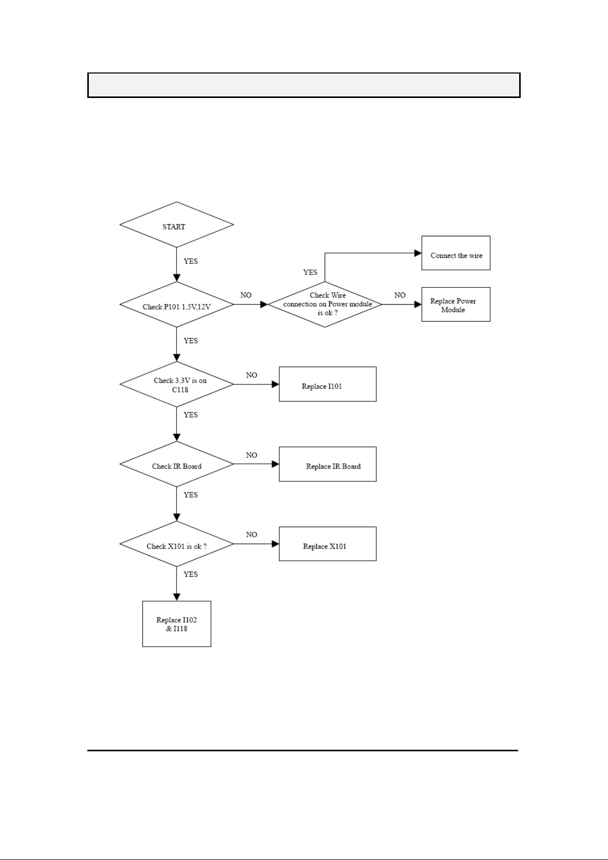
JC279ET61S Service Manual
10. TROUBLE SHOOTING FLOW CHART
10.1. NO POWER
-31-
05/12/2010
Page 33

JC279ET61S Service Manual
10.2. NO VOICE
-32-
05/12/2010
Page 34

10.3 NO DISPLAY
JC279ET61S Service Manual
-33-
05/12/2010
Page 35

JC279ET61S Service Manual
-34-
05/12/2010
Page 36

JC279ET61S Service Manual
11. ADJUSTMENT
11.1. ADJUSTMENT CONDITIONS AND PRECAUTIONS
11.1.1. Approximately 30 minutes should be allowed for warm up before proceeding.
11.1.2. Adjustments should be undertaken only on those necessary elements since most of them.
11.1.3. have been carefully preset at the factory.
11.1.4. ESD protection is needed before adjustment.
11.2.
MAIN ADJUSTMENTS
NO. FUNCTION DESIGNATION
1. Eeprom Initial Function Key
2. White Balance Function Key
11.3.
ALIGNMENT PROCEDURES
11.3.1 Adjustment Conditions and Precautions:
11.3.1.1. Power supply voltage:
AC 220V ± 10% 50 Hz ± 5%.
11.3.1.2. Warm up time:
The display must be power ON for at least 30 minutes.
11.3.1.3. Signals: reference the front detail specifications and timing table.
Video : reference the front detail specifications.
11.3.2 Eeprom Initial:
A. Timing: 1440x900 @ 60Hz
B. PATTERN:16 ×12 pane
C. Press “ INPUT “, “CH+” and “POWER” key go to factory mode
D. Figure 1,Select EEPROM INITIAL and press “► “. The act of EEPROM INITIAL
is completed when EEPROM INIT disappeared.
11.3.3 White Balance Adjustment :
A.
Enter to the factory mode, Source select “ D_Sub , Use 1440×900 @ 60Hz the
pattern is “ 5 block “ , then move the cursor to the White Balance . Press “► “ key.
That will do auto white balance
B.
After auto white balance, switch to the full white pattern then check the color
temperature.
WARM x=0.332 ± 0.03 y=0.350 ± 0.03
NORMAL x=0.313 ± 0.03 y=0.329 ± 0.03
COOL x=0.283 ± 0.03 y=0.297 ± 0.03
-35-
05/12/2010
Page 37

JC279ET61S Service Manual
C.
Enter to the factory mode, Source select “ YPbPr “, Use NTSC Color Bar (FLUKE
54200 ) , Set Color bar to 100 IRE then move the cursor to the White Balance . Press
“► “ . That will do auto white balance. Finally change 16 gray scale must be claire in
each grays.
11.4. Power Consumption Check ( VGA MODE )
11.4.1 Power Consumption Check ( VGA MODE )
A. TIMING: 1920 x 1080@60Hz
B. Pattern: 1010UPRIGHTNESS PATTERN
C. BRIGHTNESS=MAX, CONTRAST=MAX.
D. The power that each MODE consumed is shown in Chart 1.
MODE
NORMAL
Stand-by
11.4.2 Check the position of the picture displayed and phase auto adjusting (VGA MODE).
Depend on the TIMING of TIMING TABLE (TABLE 3) to switch MODE in order, stay
about 10 seconds each MODE, it can changed and stored automatically each MODE. We
can’t switch over to the next MODE until AUTO ADJUST disappears.
11.4.3 HDMI MODE FUNCTION TEST
A.DVI MODE: Depend on the TIMING of TIMING TABLE (TABLE 3 ) to check
MAX POWER COMSUMED POWER LED COLOR
70W(Normal), 80W(max) BLUE
1 W (max) Amber
Chart 1
-36-
05/12/2010
Page 38

JC279ET61S Service Manual
MODE in order.
B.HDMI MODE: make sure the 480i, 480p, 720p, 1080i ,108pTIMING is right.
11.4.4 OSD FUNCTION TEST
A. Time: 1360x768@60Hz
B. Pattern: 16*12 pane
C. Make sure that Each FUNCTION has one right action.
11.4.5 DTV FUNCTION TEST
A. Select input source to TV,
B. Input USA air channel (TABLE 1) and USA CATV channel for TV channel. .
11.4.6 YPbPr, S-VIDEO, AV, FUNCTION TEST
A. Input YPbPr, S-VIDEO, AV , signal and check.
B. Under YPbPr MODE, Make sure the 480i, 480P, 720P, 1080i ,1080p is right.
11.4.7 AUDIO FUNCTION TEST
A. Audio input includes PC AUDIO IN, S-VIDEO/AV AUDIO IN and YPbPr AUDIO
IN.
B. Under PC MODE, input PC AUDIO signal, checks whether the action of AUDIO IN
is right.
C. Under S-VIDEO/AV MODE, input L/R AUDIO signal, checks whether the action of
AUDIO IN is right.
D. Under YPbPr MODE, input L/R AUDIO signal, checks whether the action of AUDIO
IN is right.
E. Under HDMI MODE, checks whether the action of AUDIO IN is right.
F. Under DTV MODE, checks whether the action of SPDIF is right.
G. AUDIO OUT FUNCTION TEST: Under all patterns except PC pattern, The Audio
output meets active extra speaker, examines whether the extra speaker makes the
sound.
11.4.8 EARPHONE FUNCTION TEST
Under PC MODE, input PC AUDIO signal, determines whether the action of INT
SPEAKER output is right. Meets earphone with the EARPHONE, Determined whether
the action of EARPHONE output is normal.
11.4.9 All Modes Reset
After final QC step, we must to erase all saved changes again and restore the factory
defaults.
You should do “Memory Recall” again.
Turn off the LCD TV by pressing “Power” button.
-37-
05/12/2010
 Loading...