

Page 1
47″LCD TV AOC L47H861
Service
Service
Service
31~60 kHz
Description Page Description Page
Table Of Contents.......……..............................…........1
Important Safety Notice.......................................……......2
Revision List…………………………………………………3
1. General Specification..............................………........4
2. Operating Instructions…………………….……….......5
2.1. The Use Of Remote Control…….………….…….......5
2.2. To Use The Menu…...…………………….……….......6
2.3. How To Connect…….…………..………….……….....8
2.4. Front Panel Control Knobs……………….……….....13
3. Input/Output Specification…………....................…....14
4. Mechanical Instructions…………………….................16
5. Repair Flow Chart ……………………….…….…….....19
6. PCB Layout ………………..……………….....….......24
ANY PERSON ATTEMPTING TO SERVICE THIS CHASSIS MUST FAMILIARIZE HIMSELF WITH THE
TABLE OF CONTENTS
6.1.Main Board…………..……………...……….......24
6.2.Power Board……………..………….……….......27
6.3.Key Board………………………..……….......30
6.4.IR Board…………………………..……….......30
7. White-Balance, Luminance Adjustment...................31
8. Block Diagram.……...........................................33
9. Schematic……………...…………..………………...34
9.1 Main Board…………………………………...….......34
9.2.Power Board…………….…………...………….......49
9.3.Key Board……………….……….………….......53
9.4.IR Board………………………………..……….......54
10. Exploded View………………………………….…...55
11. BOM List……………….…………………………….56
12.Different Parts List……………………………………81
SAFETY NOTICE
Horizontal Frequency
CHASSIS AND BE AWARE OF THE NECESSARY SAFETY PRECAUTIONS TO BE USED WHEN SERVICING
ELECTRONIC EQUIPMENT CONTAINING HIGH VOLTAGES.
CAUTION: USE A SEPARATE ISOLATION TRANSFOMER FOR THIS UNIT WHEN SERVICING
1
Page 2
47″LCD TV AOC L47H861
Revision List
Version Release Date Revision Instructions TPV Model
A00 July.-31-2008 Initial Release E478MZNKW8A52N
E478MZNKW8AENN
A01 Sep-28-2008 Add ne BOM
E478MZNSW8AENN
2
Page 3

47″LCD TV AOC L47H861
Important Safety Notice
Proper service and repair is important to the safe, reliable operation of all AOC Company Equipment. The service
procedures recommended by AOC and described in this service manual are effective methods of performing
service operations. Some of these service operations require the use of tools specially designed for the purpose.
The special tools should be used when and as recommended.
It is important to note that this manual contains various CAUTIONS and NOTICES which should be carefully read in
order to minimize the risk of personal injury to service personnel. The possibility exists that improper service
methods may damage the equipment. It is also important to understand that these CAUTIONS and NOTICES ARE
NOT EXHAUSTIVE. AOC could not possibly know, evaluate and advise the service trade of all conceivable ways in
which service might be done or of the possible hazardous consequences of each way. Consequently, AOC has not
undertaken any such broad evaluation. Accordingly, a servicer who uses a service procedure or tool which is not
recommended by AOC must first satisfy himself thoroughly that neither his safety nor the safe operation of the
equipment will be jeopardized by the service method selected.
Hereafter throughout this manual, AOC Company will be referred to as AOC.
WARNING
Use of substitute replacement parts, which do not have the same, specified safety characteristics might create
shock, fire, or other hazards.
Under no circumstances should the original design be modified or altered without written permission from AOC.
AOC assumes no liability, express or implied, arising out of any unauthorized modification of design.
Servicer assumes all liability.
FOR PRODUCTS CONTAINING LASER:
DANGER-Invisible laser radiations when open AVOID DIRECT EXPOSURE TO BEAM.
CAUTION-Use of controls or adjustments or performance of procedures other than those specified herein may
result in hazardous radiation exposure.
CAUTION -The use of optical instruments with this product will increase eye hazard.
TO ENSURE THE CONTINUED RELIABILITY OF THIS PRODUCT, USE ONLY ORIGINAL MANUFACTURER'S
REPLACEMENT PARTS, WHICH ARE LISTED WITH THEIR PART NUMBERS IN THE PARTS LIST SECTION OF
THIS SERVICE MANUAL.
Take care during handling the LCD module with backlight unit
-Must mount the module using mounting holes arranged in four corners.
-Do not press on the panel, edge of the frame strongly or electric shock as this will result in damage to the screen.
-Do not scratch or press on the panel with any sharp objects, such as pencil or pen as this may result in damage to
the panel.
-Protect the module from the ESD as it may damage the electronic circuit (C-MOS).
-Make certain that treatment person’s body is grounded through wristband.
-Do not leave the module in high temperature and in areas of high humidity for a long time.
-Avoid contact with water as it may a short circuit within the module.
-If the surface of panel becomes dirty, please wipe it off with a soft material. (Cleaning with a dirty or rough cloth may
damage the panel.)
3
Page 4
47″LCD TV AOC L47H861
1. General Specification
4
Page 5
47″LCD TV AOC L47H861
2. Operating Instructions
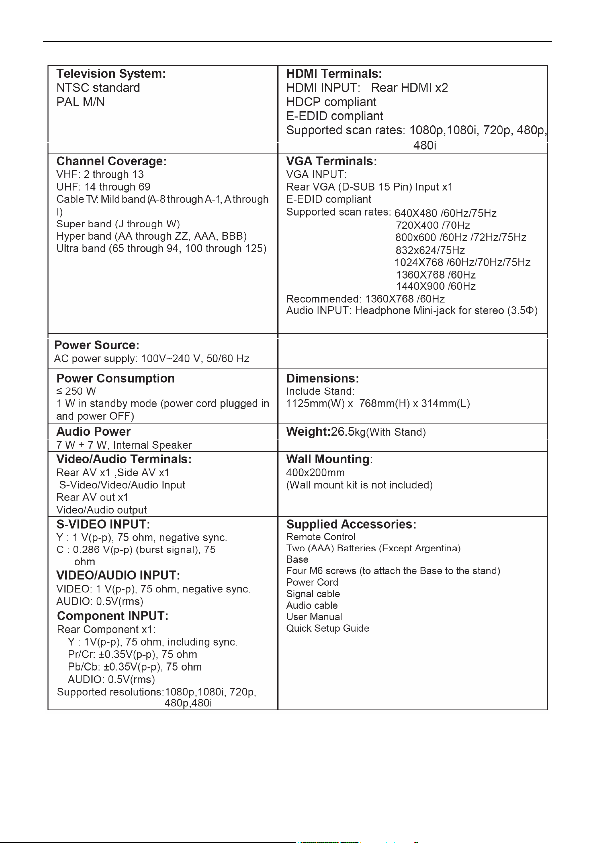
2.1 The Use of Remote Control
POWER
Press to power ON/OFF (standby)
TV.(Note:1.TV is never completely
power off.
unless physically unplugged.
2.Press to turn on TV after the power
on status LED had changed to the
red color and stopped flashing. )
VIDEO
Press repeatedly to choose
S-Video/Composite source mode (Video
1 ~ 2).
COMP
Press repeatedly to choose Component
source mode (Video 3 ).
PC/HDMI
Press repeatedly to choose VGA or
HDMI source mode (Video 4 ~ 6).
TV
Press to choose ATSC/NTSC TV source
mode.
0 ~ 9 /- number
Press to enter TV channel number to
select channel (Press ‘-’ to indicate
choosing the sub-channel).
SLEEP
Press to set a time period (off/5 min /10
min /15 min /30min/45 min
/60min/90min/120 min /180 min /240
min)after which the TV should switch
itself to standby mode.
FREEZE
Press to freeze the displayed picture
CH-/ CH +
Press + or - to browse through the TV
channels.
MENU
Press to open or exit menu.
“∧”,“∨”,“<”,“>”, “ENTER
Press to adjust the various function
items on the menu.
PREV CH
Press to display the previous TV .
MTS/SAP
Press to activate the NTSC TV
sounds, such as: Stereo, SAP or
Mono tone. And languages of DTV.
WIDE
Press to choose the display aspect
as: Normal, Wide, Zoom or Cinema
mode.
SOURCE
Press repeatedly to choose the
various input sources (Video 1 ~ 6).
EPG
This function is not support.
MUTE
Press to set TVsound mute ON/OFF
DISPLAY
Press to show the information about
the input source、TV channel、display
resolution and current time.
VOL- / VOL+
Press + or - to adjust the volume.
Exit
Press to exit menu or OSD.
V-CHIP
Press to lock / unlock Parental
Control temporarily. (After setting the
restricted table of MPAA or TV
Rating.)
VIDEO ADJ
Press to choose the Brightness or
Contrast adjustment.
AUDIO ADJ
Press to switch the ATSC
multi-channel TV sounds.
CC
Press repeatedly to change the
closed caption type as CC ON/CC
OFF/CC ON WHEN MUTE.
FAVOR IT E
Press to toggle the Favorite/Normal
mode.
5
Page 6
47″LCD TV AOC L47H861
2.2 To Use the Menus
1. Press the MENU button to display the main menu
2. Use the cursor up/down to select a menu item.
3. Use the cursor left/right to enter a submenu.
4. Press the ENTER button to enable/disable the function.
5. Press the MENU or EXIT button to exit the menu.
Press the MENU button to enter the main OSD (On Screen Display). Adjust theitems including Setup menu, Video
menu, Audio menu and Feature menu.However, some function items in the menus may only be enabled in the
particular source modes.
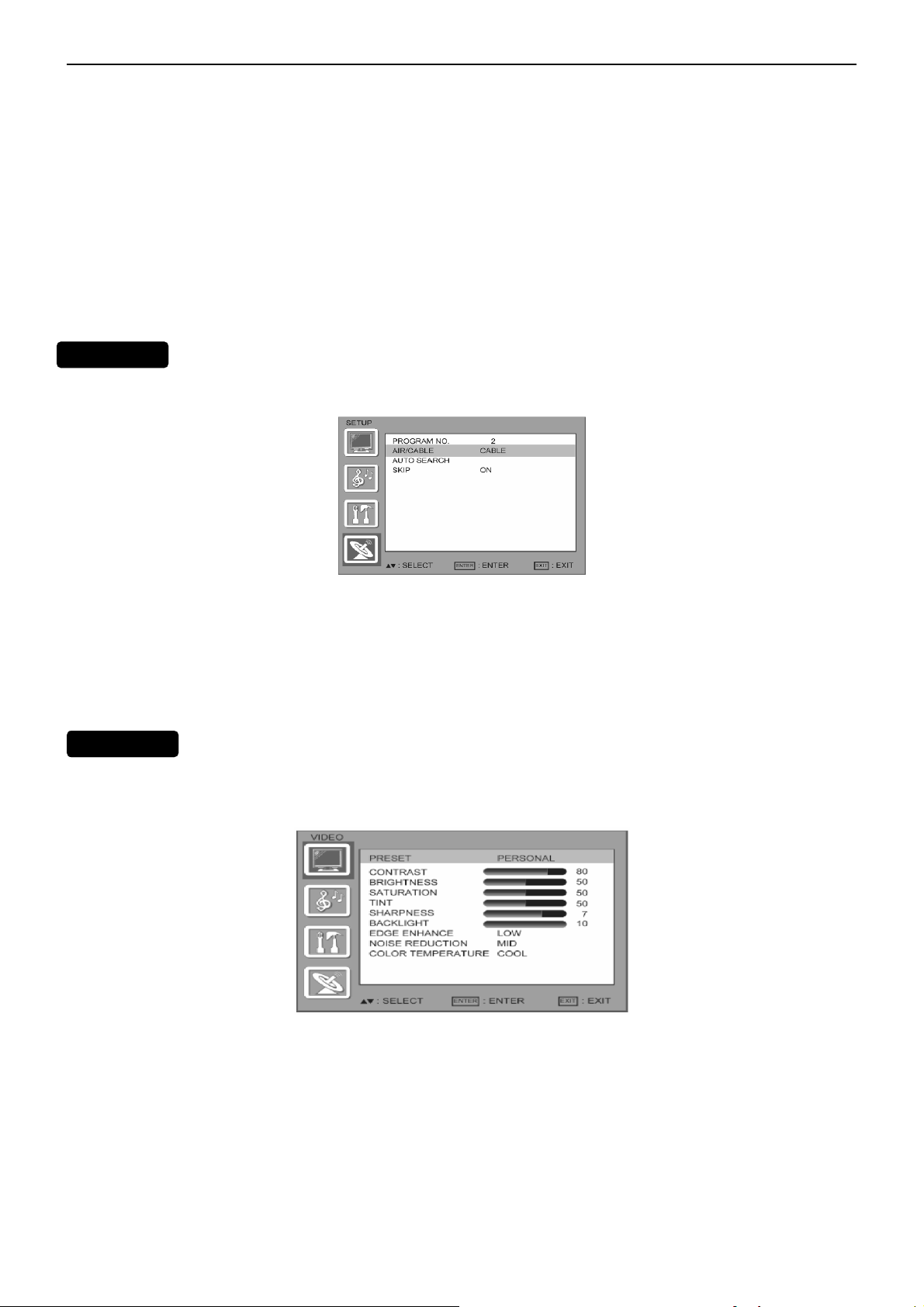
SETUP MENU
The Setup menu in TV mode shows as below. In others source modes, the Setup menu only shows Menu
Language and Aspect Ratio items.
1. PROGRAM NO: Show the TV channel label menu for user modifying channel labels specifically.
2. AIR/ CABLE: Select TV source signal from the Air (antenna) or Cable (CATV).
3. AUTO SEARCH: Automatically scan all NTSC TV channels and then store in the channel table. In channel scan
process, the OSD can display the number of channels which had been found.
4. SKIP :you can select the ship ON/OFF ,so that the program no channel can be delete or added.
VIDEO MENU
The Video menu in most source modes shows as below. It provides several videoadjustment items for user fine
tuning the video display. Only in VGA sourcemodes, the Video menu simply provides Contrast, Brightness, Back
light and Settings (Preset) items.
If you selected PERSONAL, press or to highlight an option, then press ∧or ∨ to adjust the option. You can adjust:
1. CONTRAST: Video contrast adjustment, the tuning range is 0 ~ 100.
2. BRIGHTNESS: Video brightness adjustment, the tuning range is 0 ~ 100.
3.SATURATION: COLOR saturation adjust, the tuning range is 0 ~ 100
4. TINT: Video tint adjustment, the tuning range is R50 ~ G50.
5. SHARPNESS: Video sharpness adjustment, the tuning range is 0~10
6. BACKLIGHT: Backlight strength adjustment, the tuning range is 0 ~ 10.
7. EDGE ENHANCE: Press < or > to select HIGH, OFF, or LOW.
8.NOISE REDUCTION: Press < or > to select HIGH,OFF, LOW,or MID.
9.COLOR TEMPERATURE: Press < or > to select COOL, STANDARD, or WARM.
6
Page 7
47″LCD TV AOC L47H861
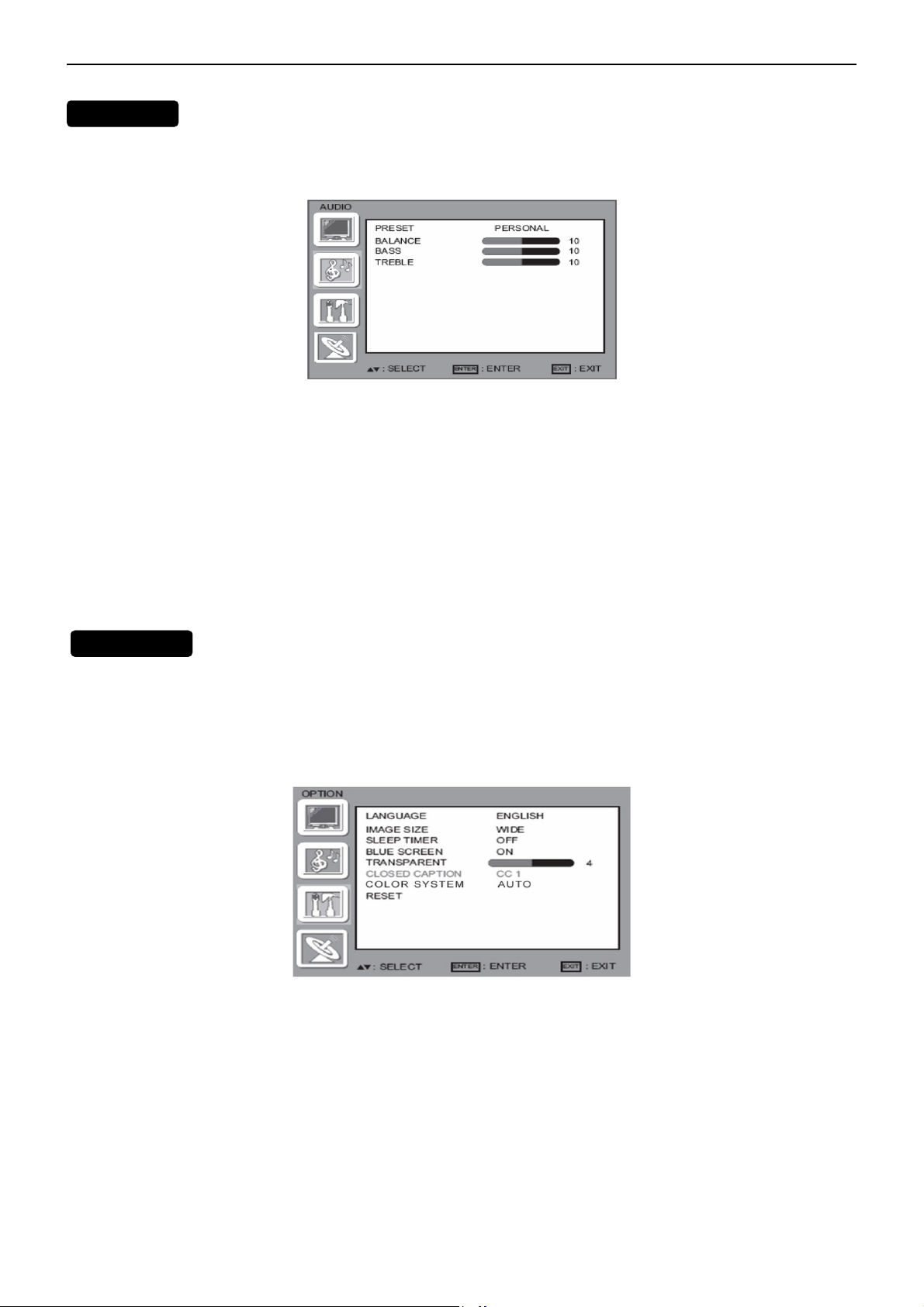
AUDIO MENU
The Audio menu in TV mode shows as below. It provides audio adjustment for user to modify the audio setting.
Audio language setting is only available with ATSC TV source, the option is disable under other source modes.
Press ∧or ∨to highlight AUDIO, then press > The AUDIO menu opens.
Press ∧or ∨ to highlight PRESET, then press < or > to select an audio mode.
You can select:
• VOICE
• MUSIC
• THEATER
• PERSONAL
If you selected PERSONAL, press ∧ or ∨ to highlight an option, then press ∧ or ∨to adjust the option. You can
adjust:
• BALANCE—Adjusts the balance between the right and left audio channels.
• BASS—Adjusts the low sounds.
•TREBLE—Adjusts the high sounds.
FEATURE MENU
The Feature menu in av/S-video mode shows as below. It provides certain optional control functions such as
inmage size, sleep timer, blue screen on/off, transparent, closed caption, color systerm. This menu gives users the
most flexibilities to satisfy their generally demands. According to the various requirements in different source modes,
certain features should be hidden
(disable) on the menu. The details footnotes will be described clearly below.
1. LANGUAGE: you can selete the ENGLISH SPANISH Portuguese French
2. IMAGE SIZE : you can selete WIDE, ZOOM, CINEMA, NORMAL
3. SLEEP TIMER: Enable or disable the TV standby timer. User can set the TV standby timer as off / 5 min / 10 min
/ 15 min/ 30 min / 45 min / 60 min/ 90 min / 120 min / 180min/ 240min. Timer starts to count down after cursor
leaving the sub-menu. (At the moment, the item shows 『** min Left』and the cursor highlights on the Feature icon.)
4. BLUE SCREEN: you can selete blue screen ON/OFF
5. TRANSPARENT: you can selete from 0 to 7
6. CLOSED CAPTION:Press or to highlight CLOSED CAPTION, then press or to select the closed captioning
mode. You can select CC1,CC2, CC3,
CC4, TT1, TT2, TT3 or TT4.
7. COLOR SYSTEM: this function you select color system,default is auto,you can choose NTSC, PAL M, PAL N.
7
Page 8
47″LCD TV AOC L47H861
V
8. RESET: you can use it reset all setting to default.
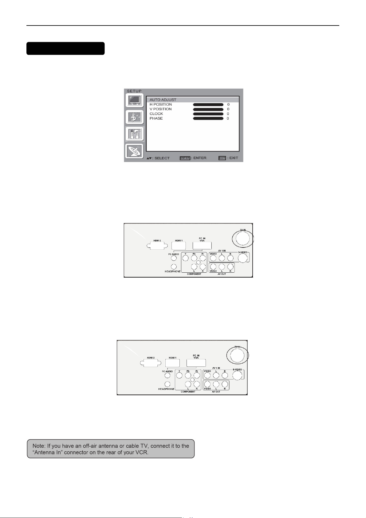
GA SETTING MENU
VGA Set: This option only shows and is available in VGA mode, which provides several items for the VGA display
fine tuning, such as : 【H-Position】,【VPosition】,【Clock】and 【Phase】. All these items giving the tuning range
from 0 to 100. 【Setting 】item provides the default VGA setting values restoring.
2.3 How to Connect
Connecting Equipment
Coaxial (RF)
Using Your Antenna or Cable for TV
1. Turn off the power to the TV.
2. Connect the coaxial (RF) connector from your antenna or cable (outof- the-wall, not from the Cable Box) to the TV
IN connector
3. Turn on the power to the TV.
4. Select TV using the INPUT button on the remote, side of the TV or directly by pressing the TV button on the
Remote Control.
Using the Antenna or Cable for your VCR
1. Turn off the power to the TV and VCR.
2. Connect the “Output to TV”, “RF Out” or “Antenna Out” connector on the rear of your VCR to the TV IN connector
at the rear of the TV.
3. Turn on the power to the TV and VCR.
4. Select TV using the INPUT button on the remote, side of the TV or directly by pressing the TV button on the
Remote Control.
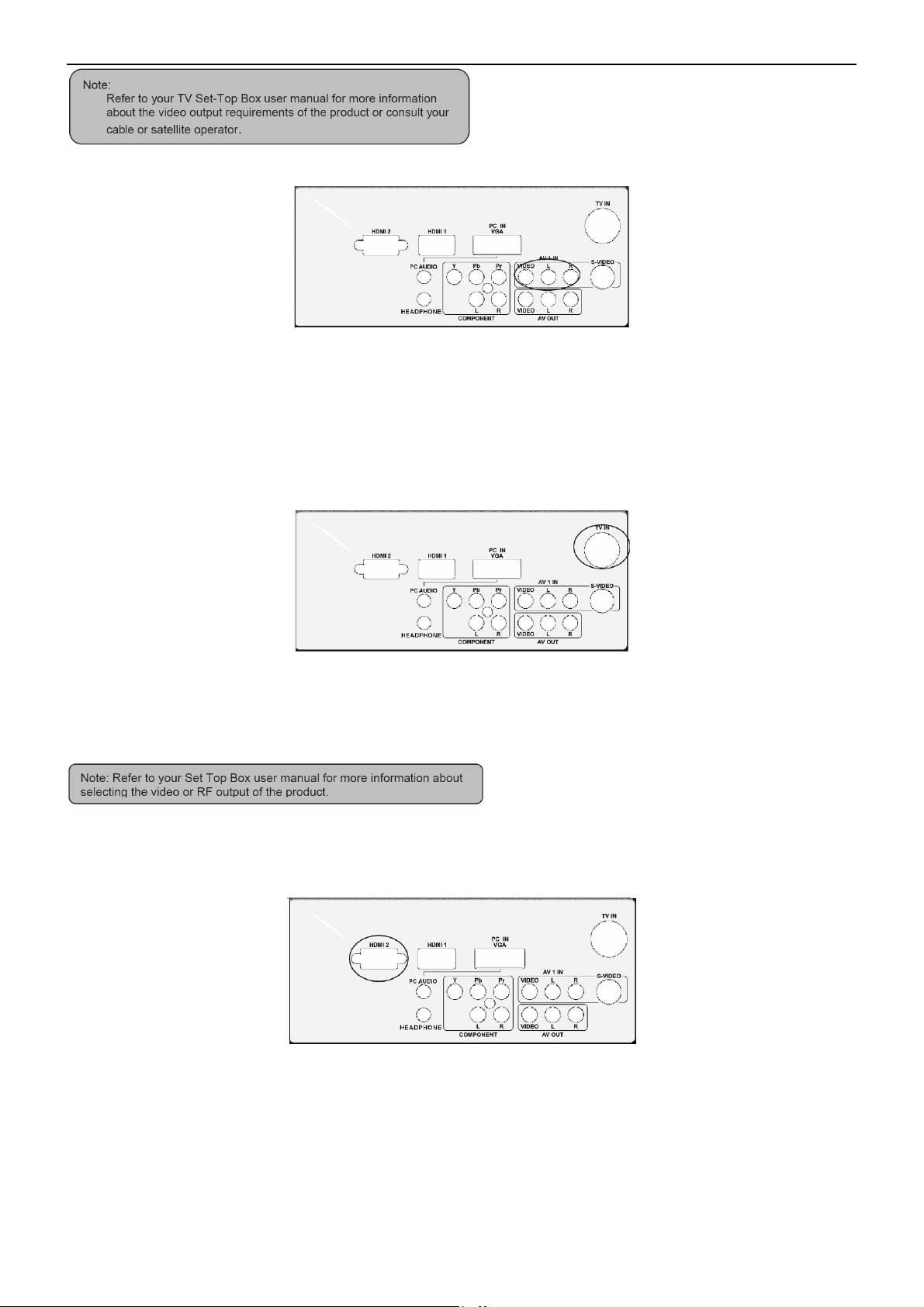
Connecting Your TV Set-Top Box
Using HDMI
TV Set-Top Boxes that have a HDMI digital interface should be connected to the HDMI input of the LCD TV for
optimal results.
8
Page 9
47″LCD TV AOC L47H861
Connecting your TV Set-Top Box (Best)
Turn off the power to the TV and TV Set-Top Box.
1. Connect a HDMI cable to the HDMI output of your TV Set-Top Box and the other end to the HDMI Input at the
rear of the TV.
2. Turn on the power to the TV and TV Set-Top Box.
3. Select HDMI using the INPUT button on the remote, side of the TV, or directly by pressing the HDMI button on the
Remote Control.
For TV Set-Top Boxes with DVI
1. Turn off the power to the TV and TV Set-Top Box.
2. Using a HDMI-DVI cable, connect the DVI end to your TV Set-Top Box and the HDMI end to the HDMI Input at
the rear of the TV.
3. Turn on the power to the TV and TV Set-Top Box.
4. Select HDMI using the INPUT button on the remote, side of the TV, or directly by pressing the HDMI button on the
Remote Control.
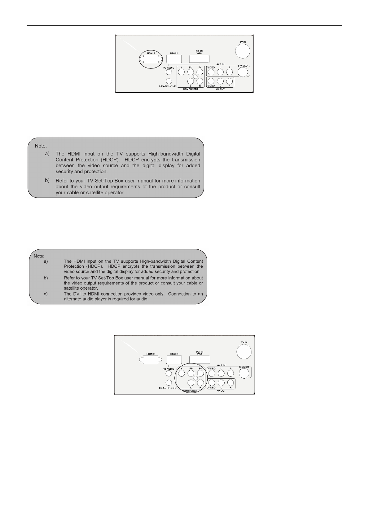
Using Component Video
Connecting your TV Set-Top Box (Better):
1. Turn off the power to the TV and TV Set-Top Box.
2. Connect the Pr (red color) connector on your TV Set-Top Box to the corresponding Pr (red color) connector in the
Component group.
3. Connect the Pb (blue color) connector on your TV Set-Top Box to the corresponding Pb (blue color) connector in
the Component group.
4. Connect the Y (green color) connector on your TV Set-Top Box to the corresponding Y (green color) connector in
the Component group.
5. Using an audio cable (red and white connectors), connect the cable to the audio output connectors associated
with the Component output on your TV Set-Top Box and connect the other end to the audio connectors associated
with the Component.
6. Turn on the power to the TV and TV Set-Top Box.
7. Select Component (Video 3) using the INPUT button on the remote, side of the TV or directly by pressing the
Component button on the Remote Control.
9
Page 10
47″LCD TV AOC L47H861
Connecting Your Basic Set-Top Box
Using Composite Video
1. Turn off the power to the TV and Set-Top Box.
2. Using an AV Cable, connect the Video (yellow color) connector on your Set-Top Box to the corresponding Video
(yellow color) connector in the AV group at the rear of the TV.
3. Using the red and white connectors, connect the cable to the audio output connectors associated with the Video
output on your Set-Top Box and connect the other end to the audio connectors associated with the AV input at the
rear of the TV.
4. Turn on the power to the TV and Set-Top Box.
5. Select Composite (Video 1) using the INPUT button on the remote, side of the TV or directly by pressing the AV
button on the Remote Control.
Using Coax (RF)
1. Turn off the power to the TV and Set-Top Box.
2. Using a Coax (RF) cable, connect one end to the TV OUT (RF) on your Set Top Box and the other end to the
DTV/TV input at the rear of the TV.
3. Turn on the power to the TV and Set-Top Box.
4. Select TV using the INPUT button on the remote, side of the TV or directly by pressing the TV button (below the
WIDE button) on the Remote Control.
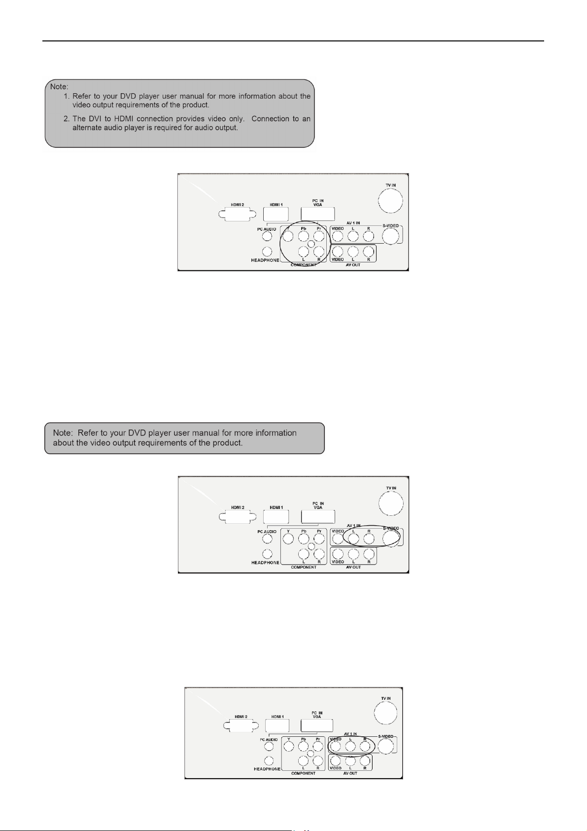
Connecting Your DVD Player
Using HDMI
DVD players that have a digital interface such as HDMI (High Definition Multimedia Interface) should be connected
to the HDMI input of the LCD TV for optimal results.
Connecting your DVD Player (Best)
1. Turn off the power to the TV and DVD player.
2. Connect a HDMI cable to the HDMI output of your DVD player and the other end to the HDMI Input at the rear of
the TV.
3. Turn on the power to the TV and DVD player.
4. Select HDMI using the INPUT button on the remote, side of the TV or directly by pressing the HDMI button on the
Remote Control.
For DVD Players with DVI:
1. Turn off the TV and DVD player.
2. Using a HDMI-DVI cable, connect the DVI end to your DVD player and the HDMI end to the HDMI Input at the
rear of the TV.
10
Page 11
47″LCD TV AOC L47H861
3. Turn on the power to the TV and your DVD player.
4. Select HDMI using the INPUT button on the remote or side of the TV, or directly by pressing the HDMI button on
the Remote.
Using Component Video
Connecting your DVD Player (Better)
1. Turn off the power to the TV and DVD player.
2. Connect the Pr (red color) connector on your DVD player to the corresponding Pr (red color) connector in the
Component at the rear of the TV.
3. Connect the Pb (blue color) connector on your DVD player to the corresponding Pb (blue color) connector in the
Component group at the rear of the TV.
4. Connect the Y (green color) connector on your DVD player to the corresponding Y (green color) connector in the
Component group at the rear of the TV.
5. Using an audio cable (red and white connectors), connect the cable to the audio output connectors associated
with the Component output on your DVD player and connect the other end to the audio connectors associated with
the Component input at the rear of the TV.
6. Turn on the power to the TV and DVD player.
7. Select Component using the INPUT button on the remote, side of the TV or directly by pressing the Component
button on the Remote Control.
Using S-Video (AV)
Connecting your DVD Player (Good):
1. Turn off the power to the TV and DVD player.
2. Connect the S-Video jack on the rear of your DVD player to the SVideo jack in the AV group on the rear of the TV.
3. Connect an audio cable (white and red connectors) to the audio output connectors associated with the S-Video
output on your DVD player and connect the other end to the audio connectors associated with the AV input on the
rear of the TV.
4. Turn on the power to the TV and DVD player.
5. Select S-Video (Video 2) using the INPUT button on the remote, side of the TV, or directly by pressing the AV
button on the Remote Control.
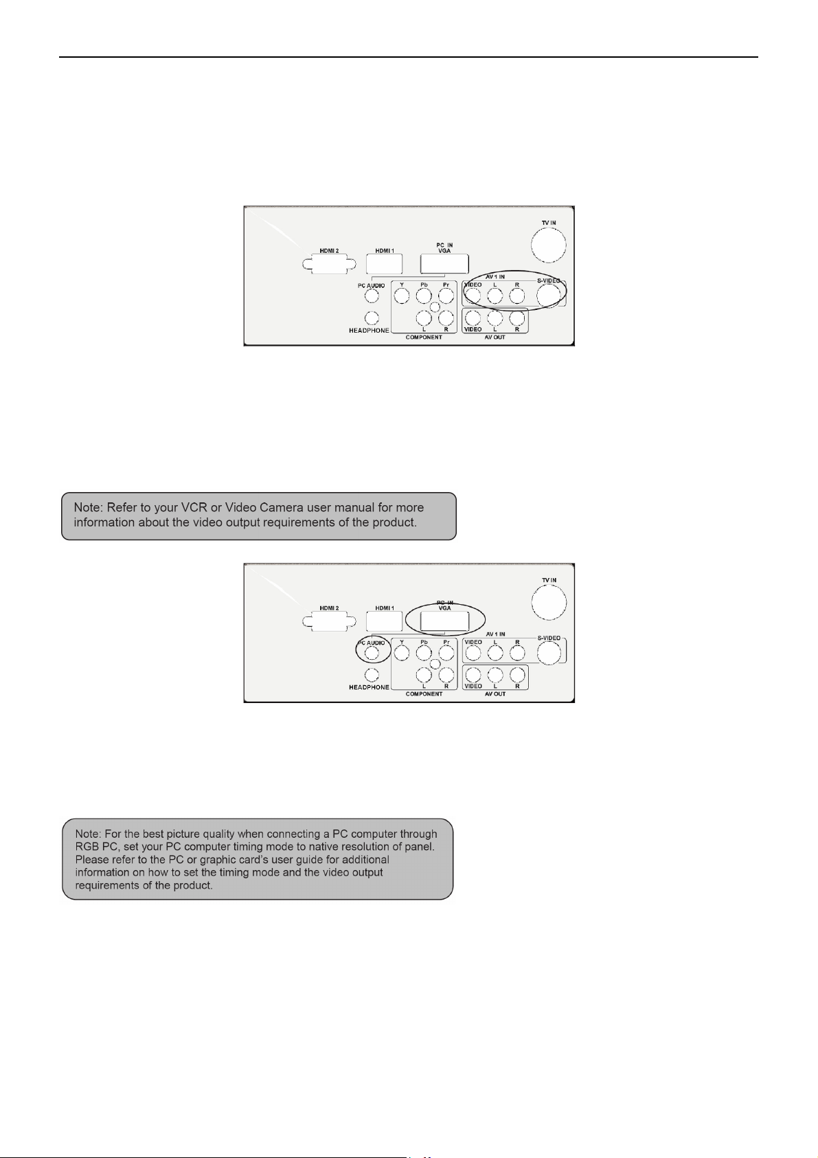
Using Composite (AV) Video
Connecting your DVD Player (Good)
11
Page 12
47″LCD TV AOC L47H861
1. Turn off the power to the TV and DVD player.
2. Connect the Video (yellow color) connector on your DVD player to the Video (yellow color) connector in the AV
group.
3. Connect the R (red color) and L (white color) audio connectors on your DVD player to the corresponding R (red
color) and L (white color) audio input connectors in the AV group.
4. Turn on the power to the TV and DVD Player.
5. Select Composite (Video 1) using the INPUT button on the remote, side of the TV or directly by pressing the AV
button on the Remote Control.
Connecting Your VCR or Video Camera
1. Turn off the TV and VCR or Video Camera.
2. Connect the S-Video jack on the rear of your VCR or Video Camera to the S-Video jack in the AV group on the
rear of the TV.
3. Connect an audio cable (white and red connectors) cable to the audio output connectors associated with the
S-Video output on your VCR or Video Camera and connect the other end to the audio connectors associated with
the AV input on the rear of the TV.
4. Turn on the power to the TV and VCR or Video Camera.
5. Select S-Video (Video 2) using the INPUT button on the remote, side of the TV or directly by pressing the AV
button on the Remote Control.
Connecting to a PC Computer
1. Turn off the power to the TV and PC Computer.
2. Connect a 15-pin D-Sub RGB (VGA) cable to the RGB output of your pc computer and the other end to the RGB
PC input at the rear of the TV.
3. Connect the Audio Out on your pc computer to the RGB PC Audio input at the rear of the TV.
4. Turn on the TV and PC Computer.
5. Select RGB using the INPUT button on the remote, side of the TV or directly by pressing the RGB button on the
Remote.
12
Page 13
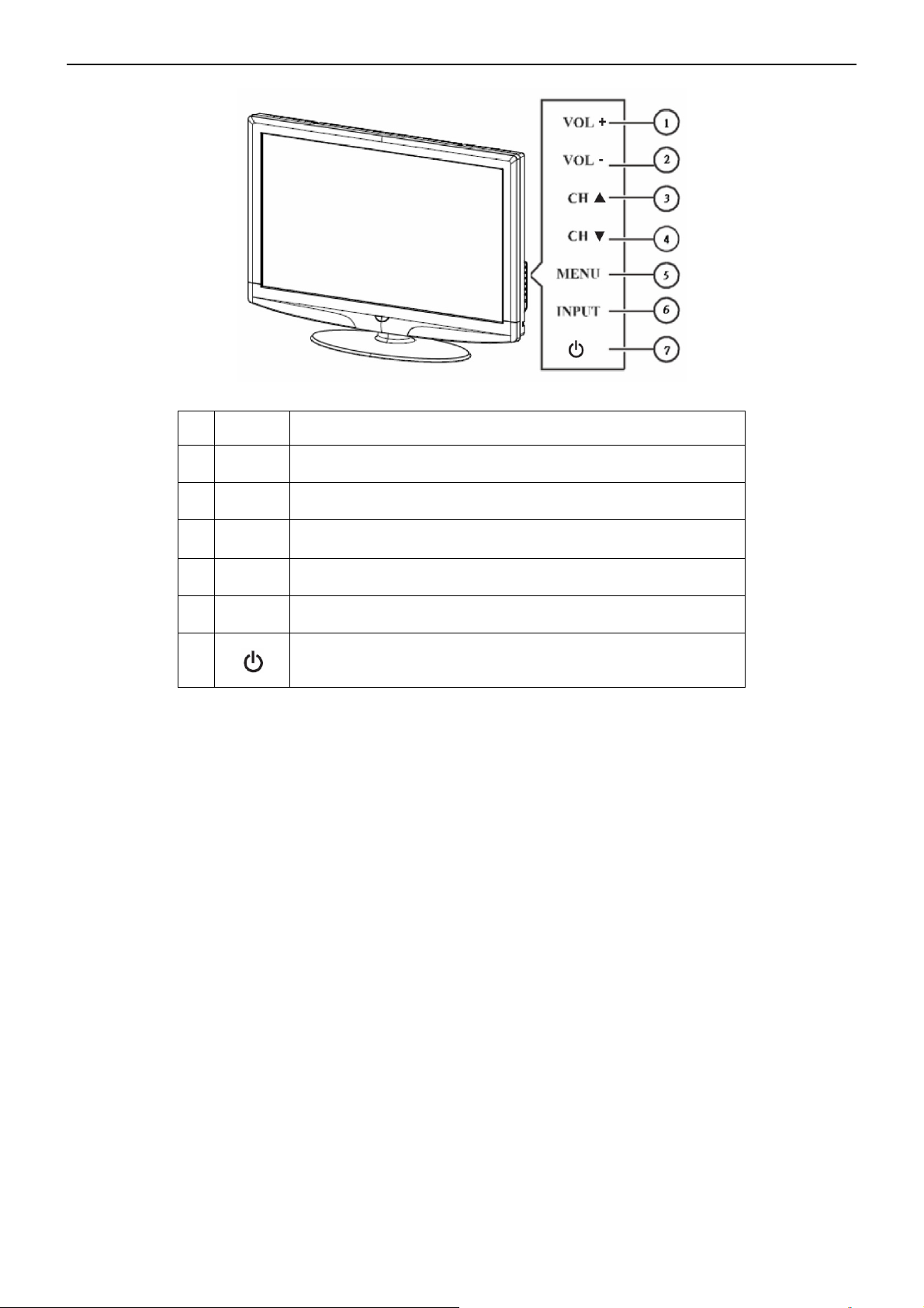
47″LCD TV AOC L47H861
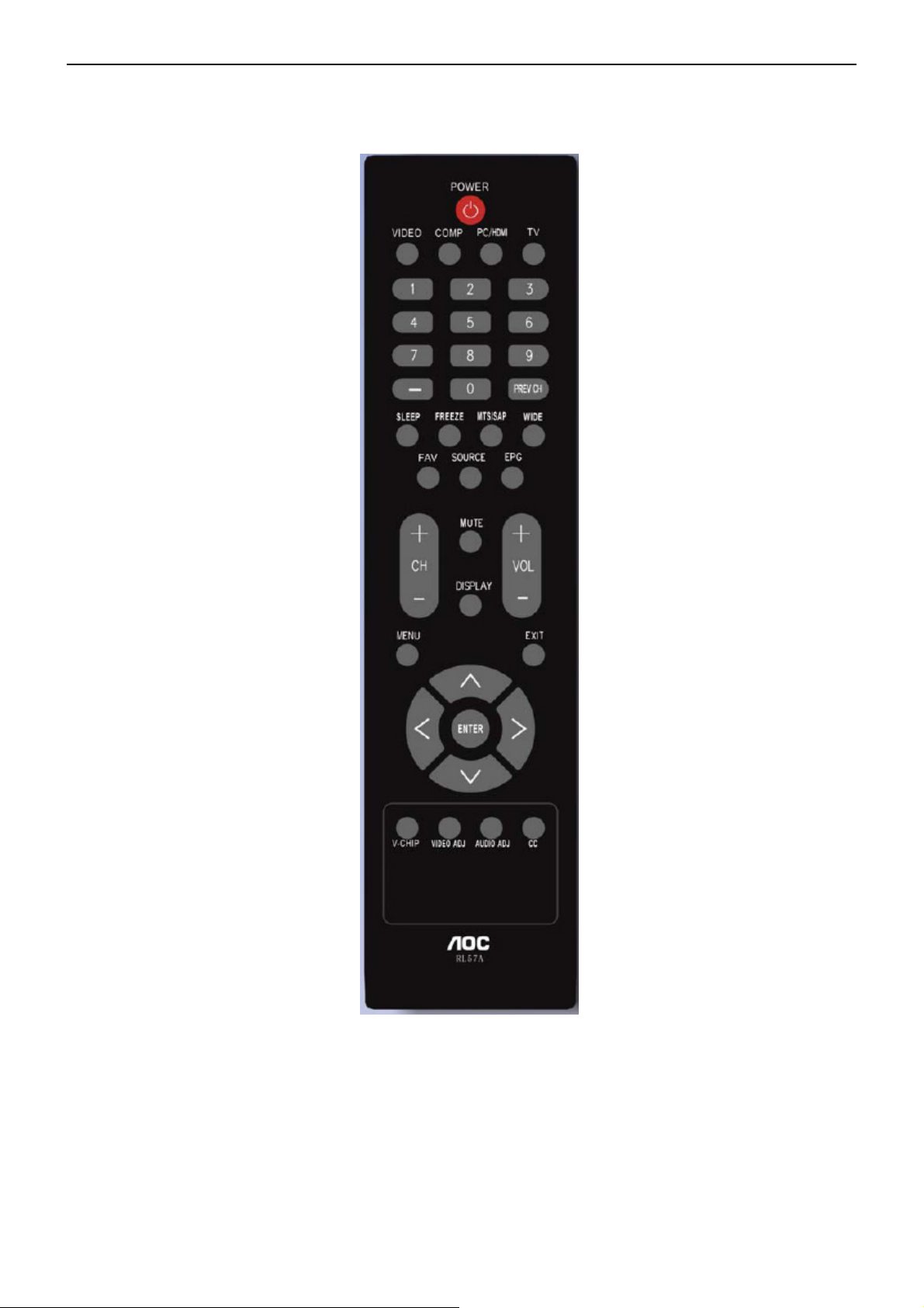
2.4 Front Panel Control Knobs
1. VOL +
2. VOL -
3. CH ▲
4. CH ▼
5. MENU
6. INPUT
7.
VOL +:
VOL - :
CH +:
CH - :
Menu key:
Source key:
Power key:
Press to increase the sound volume level.
Press to decrease the sound volume level.
Press to select the next higher Program number.
Press to select the next lower Program number.
Press
to open or exit the OSD menu.
Press to select the input source.
Press to turn on / off (standby) the TV set.
(Please re-turn on TV after the Power-ON status LED had changed
to the Red color and finished flashing.)
13
Page 14
47″LCD TV AOC L47H861
3. Input/Output Specification
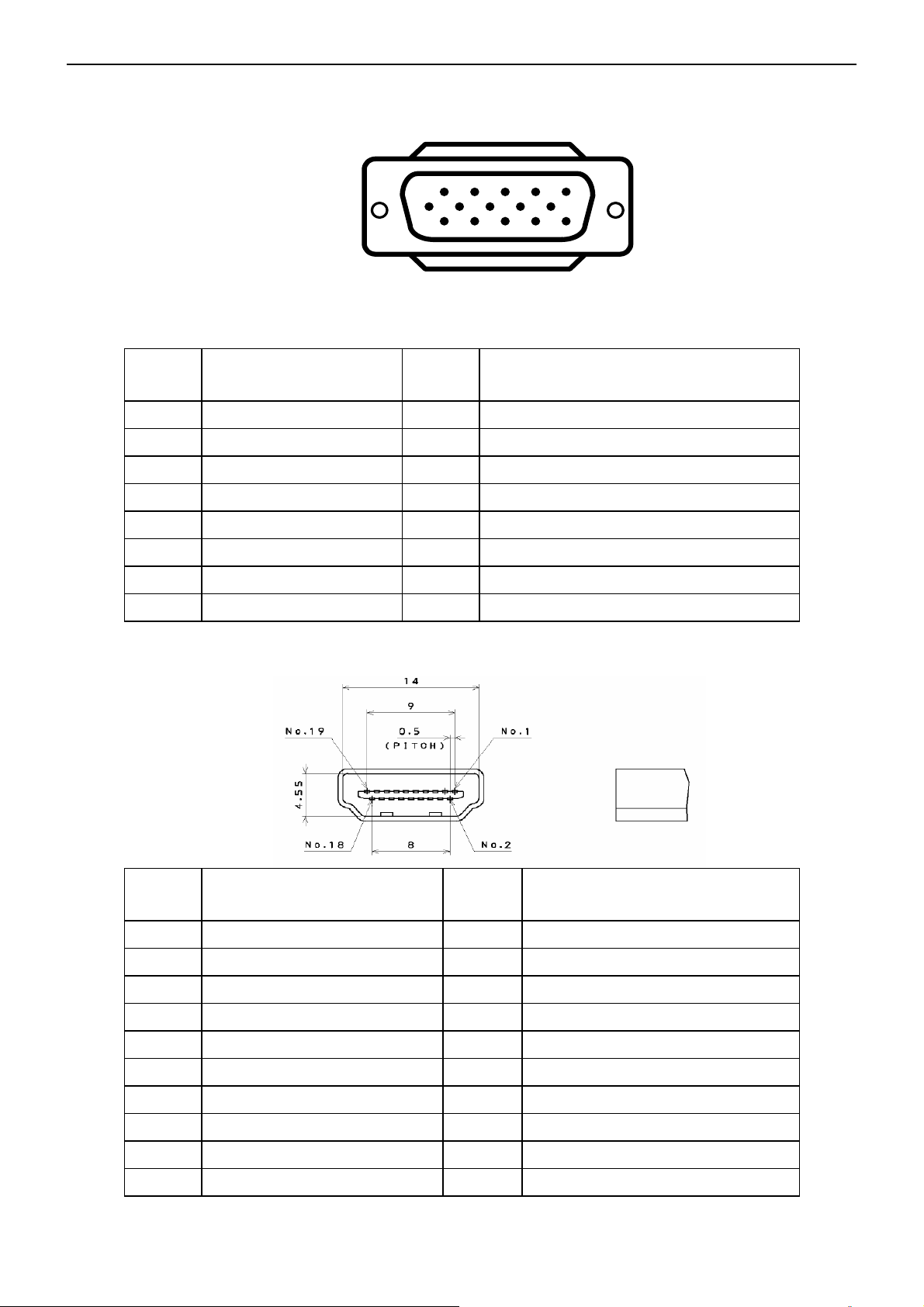
3.1 RGB Signal input
15 - Pin Color Display Signal Cable
Pin No. Description Pin No. Description
1 Red Video 9 Mandatory +5V Supply for PC Bypass
2 Green Video 10 Sync Ground
3 Blue Video 11 SDA(Remote Control)
4 SCL(Remote Control) 12 Bi-directional Data (SDA) for PC Bypass
1
6
11 15
5
10
5 Ground 13 H-Sync.
6 Red Video Ground 14 V-Sync.
7 Green Video Ground 15 Data Clock (SCL) for PC Bypass
8 Blue Video Ground
3.2 HDMI Digital connector pin assignments
Pin No. Description Pin No. Description
1 TMDS Data2+ 2 TMDS Data2 Shield
3 TMDS Data2- 4 TMDS Data1+
5 TMDS Data1 Shield 6 TMDS Data1-
7 TMDS Data0+ 8 TMDS Data0 Shield
9 TMDS Data0- 10 TMDS Clock+
11 TMDS Clock Shield 12 TMDS Clock-
13 CEC 14 NC
15 SCL 16 SDA
17 DDC/CEC Ground 18 +5V Power
19 Hot Plug Detect
14
Page 15
47″LCD TV AOC L47H861
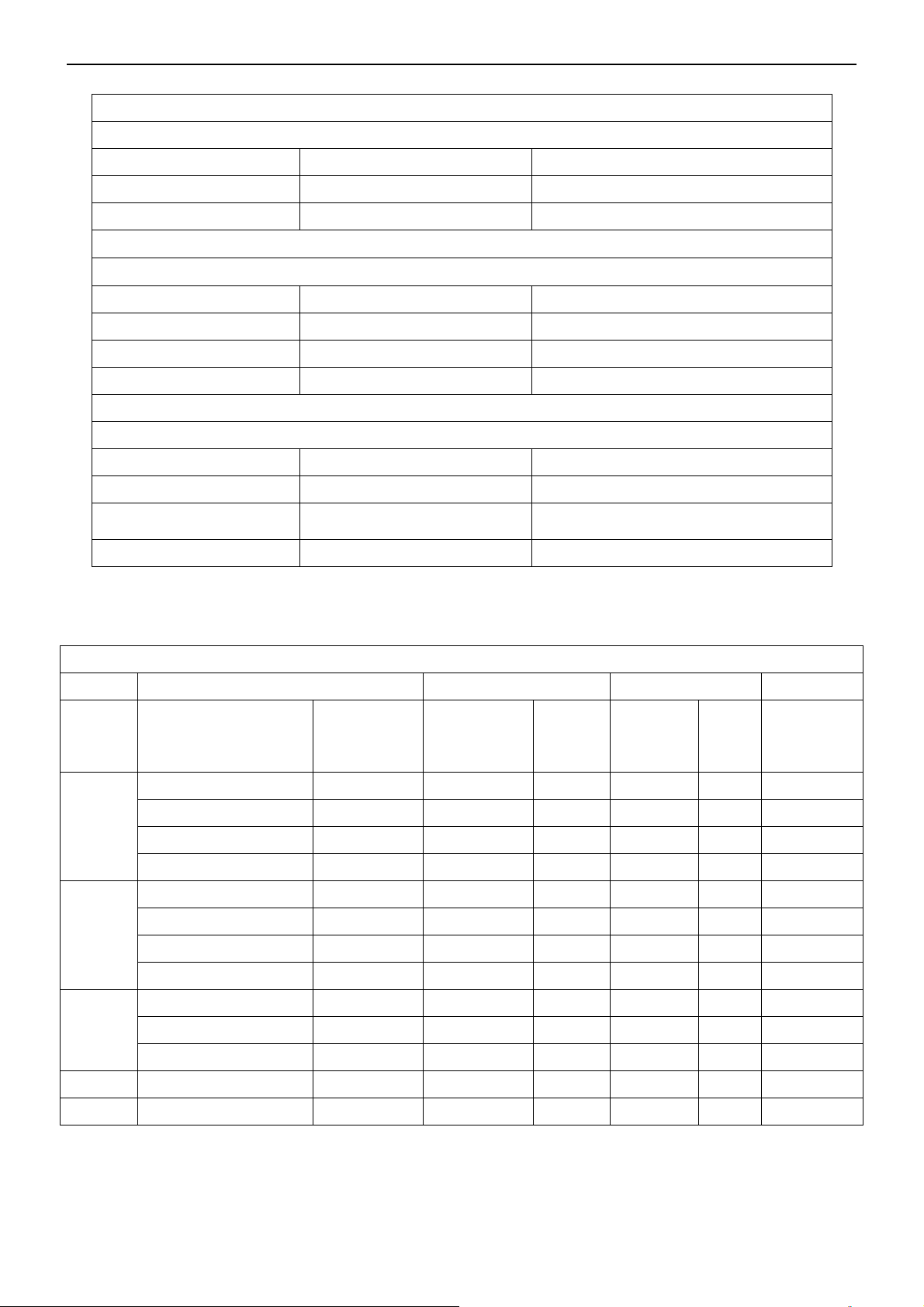
3.3 AV/S-Video/Component Video Inputs
AV (Composite Video input)
Video1
Amplitude 1.0 V (p-p), negative sync.
Impedance 75 ohm terminated
S-Video (Y / C input)
S-Video2
System NTSC
Y signal amplitude 1.0Vpp (including sync)
C signal amplitude 0.286Vpp
Impedance 75 ohm terminated
Component (Y, Pb/Cb, Pr/Cr input)
Video3
Y signal amplitude 1.0Vpp (including sync)
Impedance 75 ohm terminated
3.4 Compatible Mode Table
System NTSC
System 1080i, 480p, 720p, 480i
Cr, (R-Y) / Cb, (B-Y)
Signal amplitude
VESA MODES
±0.35Vpp, 75 ohm
Horizontal Vertical
Nominal
Mode Resolution Total
640x480@60Hz 800 x 525 31.469 N 59.940 N 25.175
VGA
SVGA
XGA
SXGA 1280x1024@60Hz 1688x1066 63.981 P 60.020 P 108.000
FHD 1920x1080@60Hz 2080x1111 66.587 P 59.934 N 138.500
640x480@72Hz 832 x 520 37.861 N 72.809 N 31.500
640x480@75Hz 840 x 500 37.5 N 75 N 31.500
720x400@70Hz 900 x 449 31.469 N 70.087 P 28.322
800x600@56Hz 1024 x 625 35.156 P 56.25 P 36.000
800x600@60Hz 1056 x 628 37.879 P 60.317 P 40.000
800x600@72Hz 1040 x 666 48.077 P 72.188 P 50.000
800x600@75Hz 1056 x 625 46.875 P 75 P 49.5
1024x768@60Hz 1344x806 48.363 N 60.004 N 65.000
1024x768@70Hz 1328x806 56.476 N 70.069 N 75.000
1024x768@75Hz 1312x800 60.023 P 75.029 P 78.750
Frequency
(KHz)
Sync
Polarity
Nominal
Freq.
(Hz)
Sync
Polarit
y
Nominal
Pixel
Clock
(MHz)
15
Page 16
47″LCD TV AOC L47H861
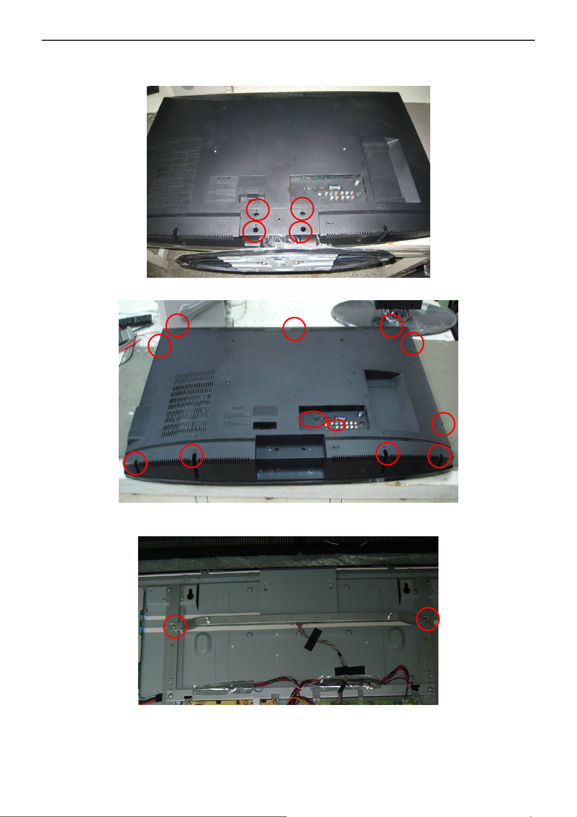
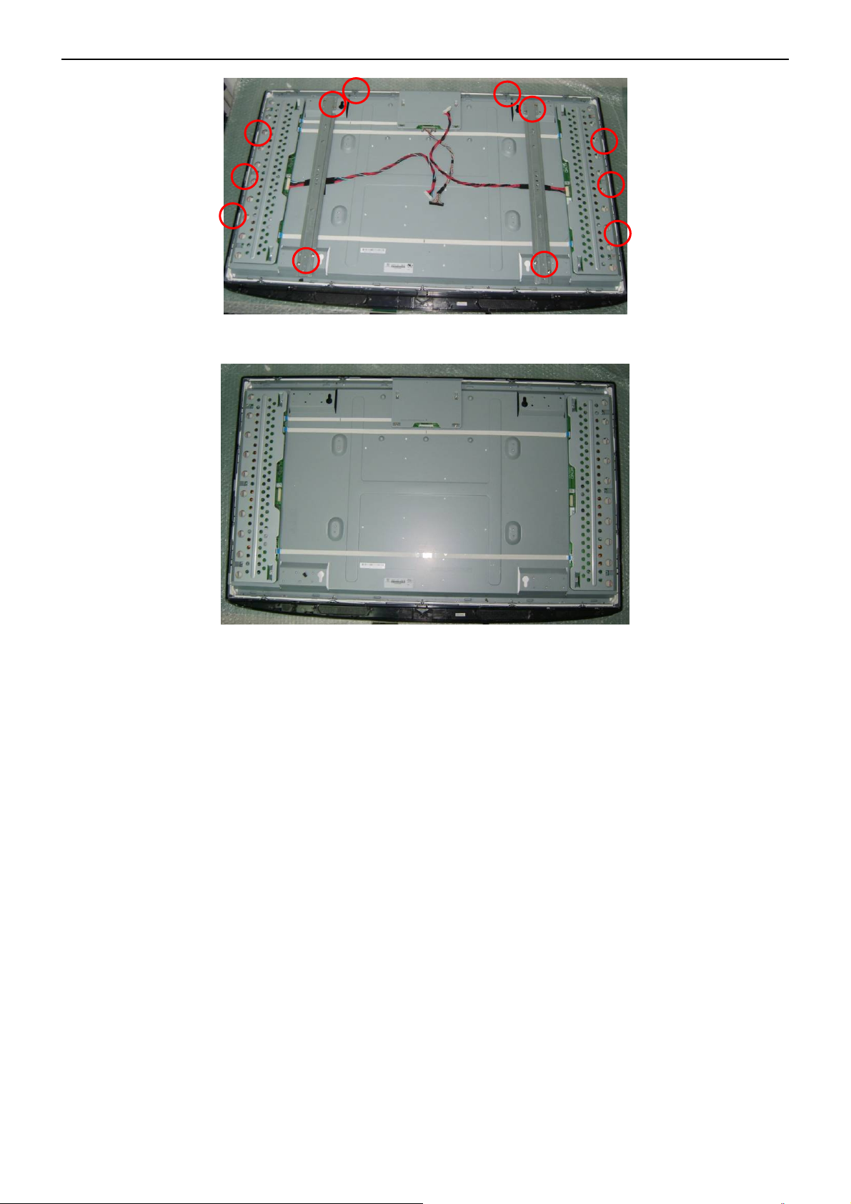
4. Mechanical Instructions
1. Remove the 4 screws to remove the stand.
2. Remove 13 screws to remove the rear cover.
3. Remove the bkt-PCB-holder,
4. Remove main board, power board.
16
Page 17
47″LCD TV AOC L47H861
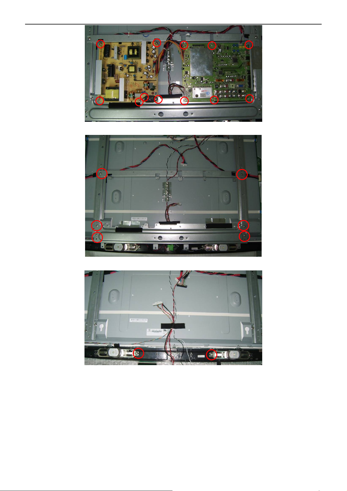
5. Remove the bkt-PCB-holder, remove key board and IR board.
6. Release the speakers.
17
Page 18
47″LCD TV AOC L47H861
7. Remove 16 screws to remove the main frame.
8. Disassembly bezel and panel.
18
Page 19
47″LCD TV AOC L47H861
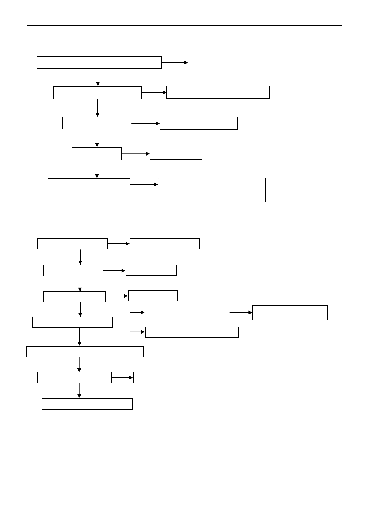
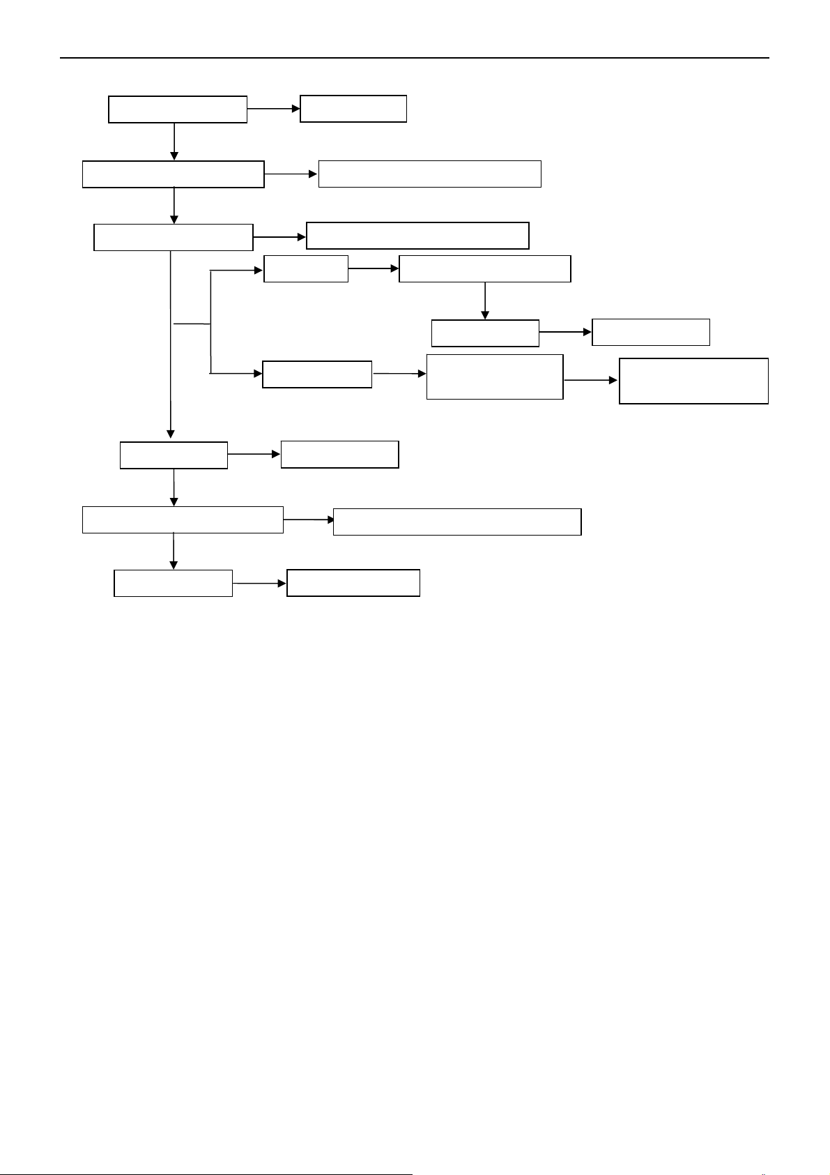
5. Repair Flow Chart
1. No Power (No LED indicator)
Check power cord and board interface
OK
NG
Plug in power cord and interface
Check F901, BD901, C908
OK
Check IC902, Q901
OK
Check T901
OK
Check D907, C921, C923,
IC905, IC906
NG
NG
NG
2. Can not start (LED indicator yellow)
Check key board
OK
Check 5V SB
NG
NG
Repair the key board
Return to “1”
NG
Replace F901 or BD901 or C908
Replace IC902 or Q901
Replace T901
Replace D907 or C921 or C923 or
IC905 or IC906
OK
Check 3.3V SB
OK
Check PWR ON signal
OK
Check main board power supply part
OK
Check U401, U402
OK
Check I2C communication
NG
NG
NG
Check U703
Check U411, X402
Check I2C communication
Replace the main board
NG
Replace U409 or X402
19
Page 20
47″LCD TV AOC L47H861
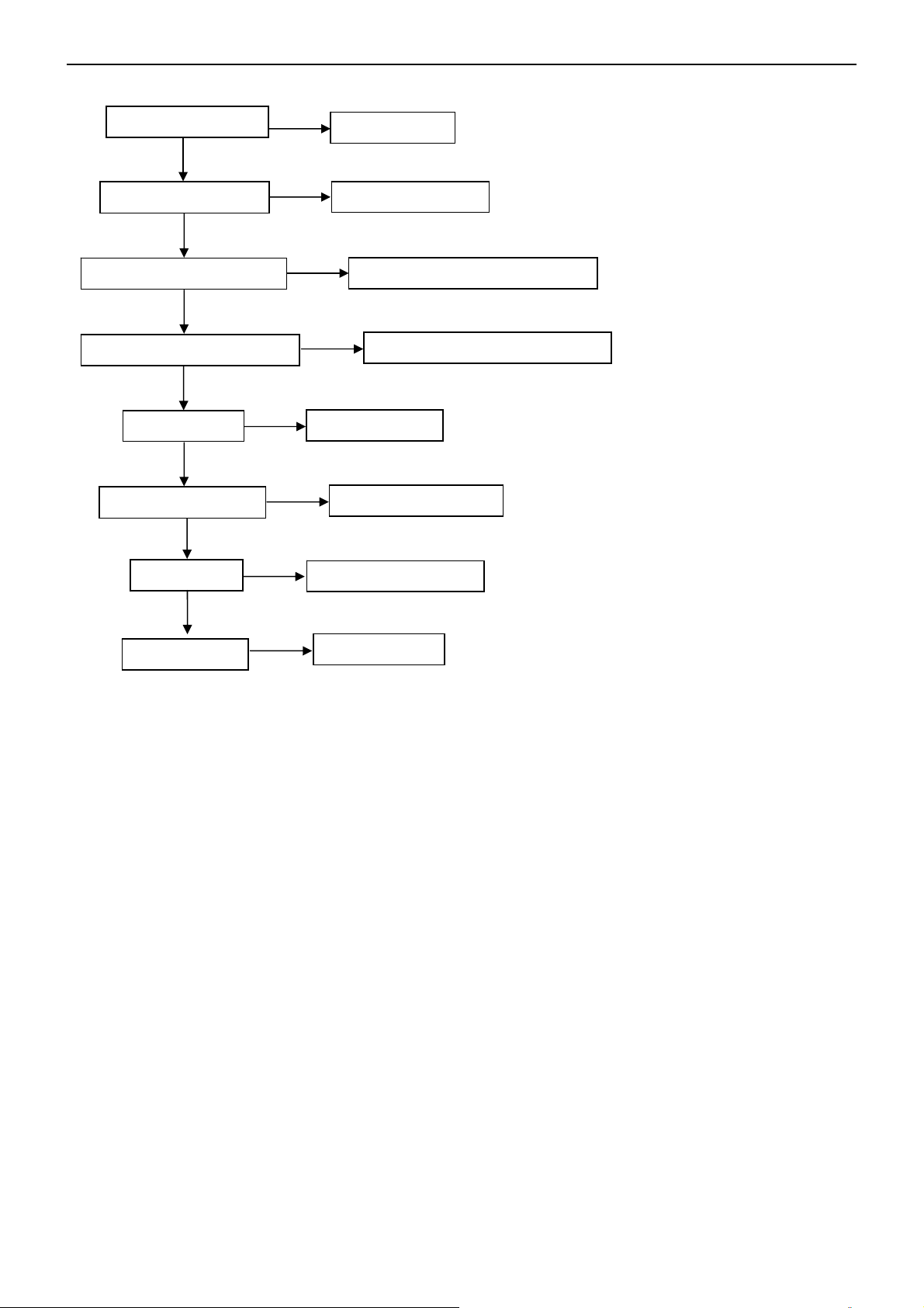
3. No display (LED indicator green)
Check the source
OK
Reset source
Check LVDS cable
OK
Check D918, IC901, Q904
OK
Check IC903, Q902, Q903
OK
Check T902
OK
Check D906, C919
OK
Check U401
OK
NG
NG
NG
NG
Reset LVDS cable
NG
NG
Replace D918 or IC901 or Q904
Replace T902
Replace D906, C919
Replace main board
Replace IC903 or Q902 or Q903
Check panel
NG
Replace panel
20
Page 21
47″LCD TV AOC L47H861
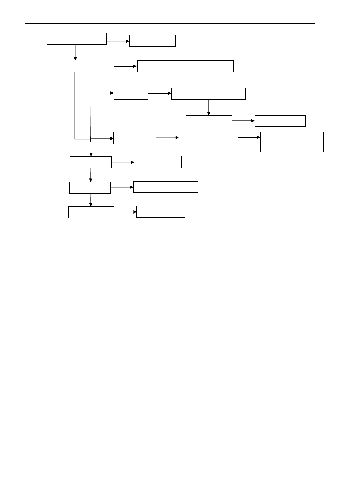
4. Abnormal display
Check the source
OK
NG
Reset source
Check signal filter circuit
OK
OK
Check U406
OK
Check U401
OK
Check panel
NG
TV signal Check TV system setup
HDMI signal
NG
NG
NG
Replace the filter or inductance
OK
Check TU201
Check U501, U502,
U503, U504
Replace U406
Replace main board
Replace panel
NG
Replace TU201
NG
ReplaceU501, U502,
U503, U504
21
Page 22
47″LCD TV AOC L47H861
p
5. No sound
Check the source
OK
Reset source
Check signal filter circuit
Check Earphone jack
OK
Check U401
Check U601, U602, U603
OK
NG
NG
SIF signal Check TV system setu
HDMI signal
NG
Replace the filter or inductance
Replace the Earphone jack
OK
Check TU201
Check U501,
U502, U503, U504
Replace U401
NG
Replace U601 or U602 or U603
NG
Replace TU201
NG
ReplaceU501,
U502, U503, U504
Check speaker
NG
Replace speaker
22
Page 23
47″LCD TV AOC L47H861
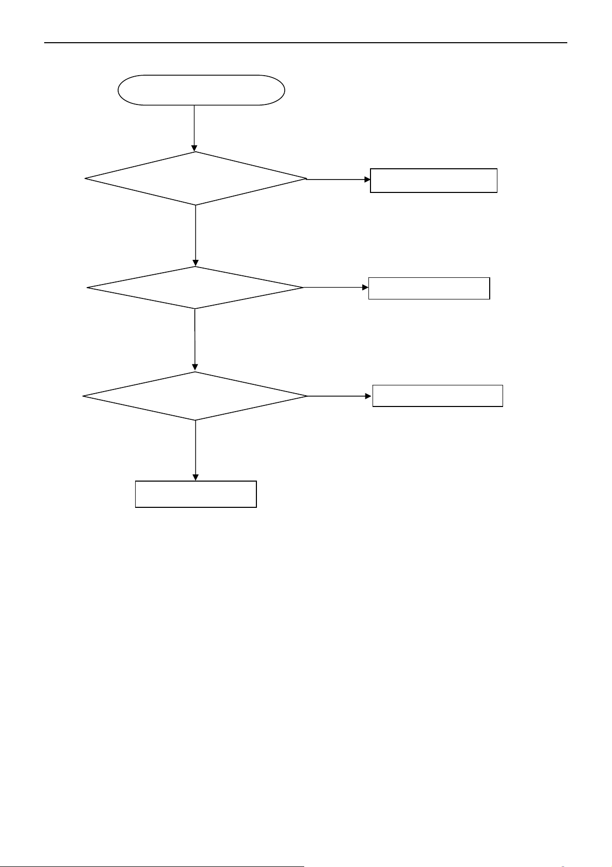
6. Key Board
OSD is unstable or not working
Is Key Pad Board connecting normally?
Y
Is Button Switch normally?
Y
Is Key Pad Board Normally?
Y
Check Main Board
N
Connect Key Pad Board
N
N
Replace Button Switch
Replace Key Pad Board
23
Page 24
47″LCD TV AOC L47H861
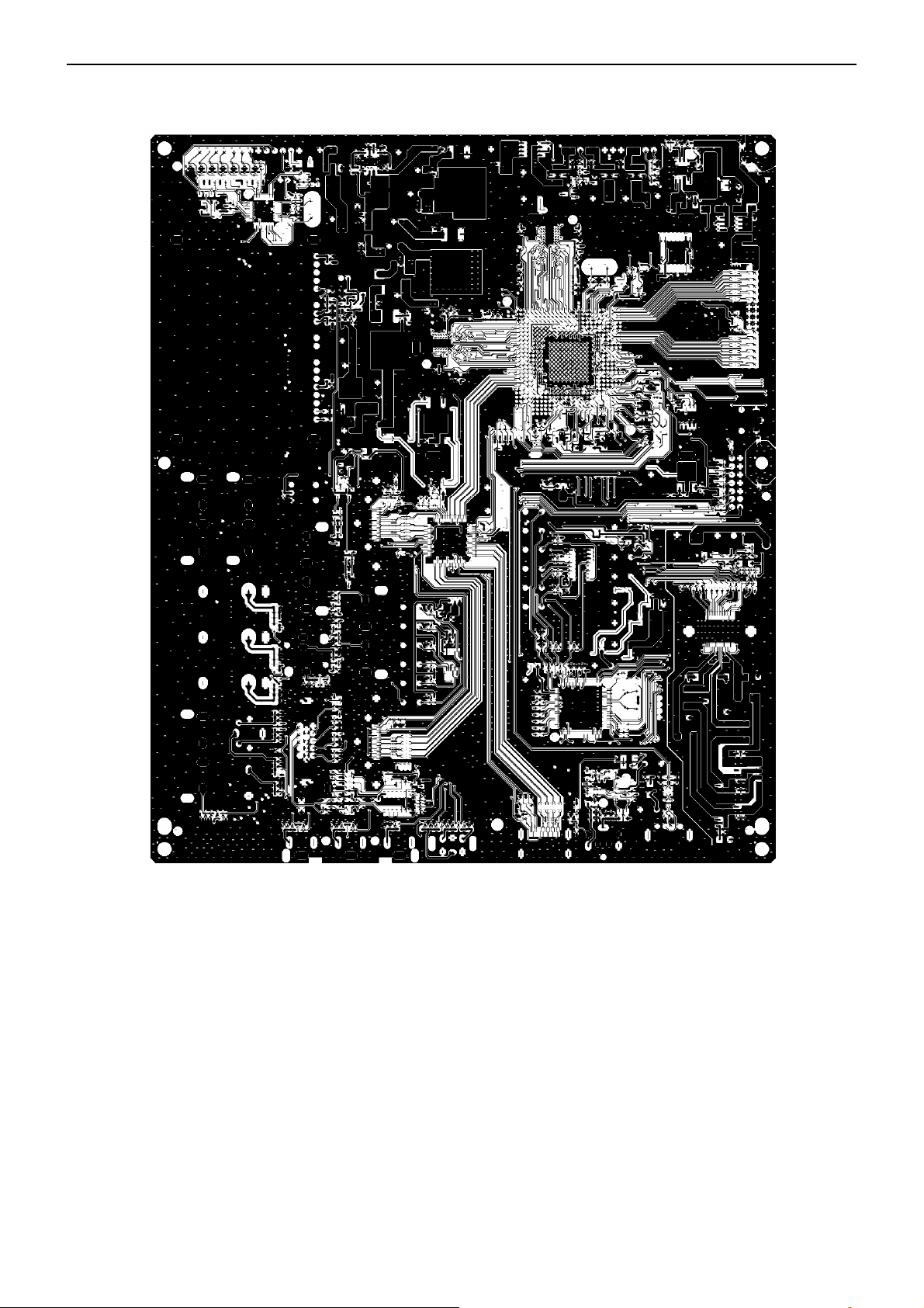
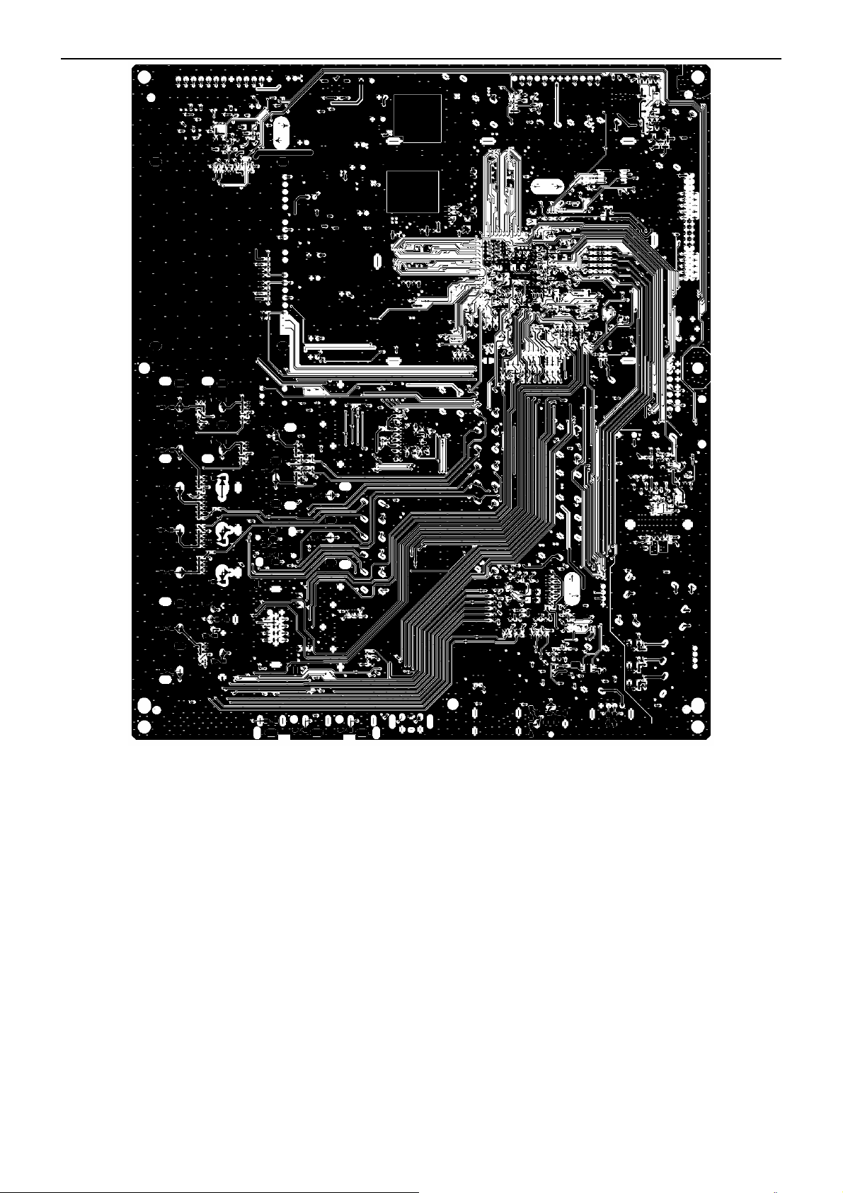
6. PCB Layout
6.1 Main Board
24
Page 25
47″LCD TV AOC L47H861
25
Page 26

47″LCD TV AOC L47H861
26
Page 27

47″LCD TV AOC L47H861
6.2 Power Board
27
Page 28

47″LCD TV AOC L47H861
28
Page 29

47″LCD TV AOC L47H861
29
Page 30

47″LCD TV AOC L47H861
6.3 Key Board
6.4 IR Board
30
Page 31

47″LCD TV AOC L47H861
7. White Balance, Luminance Adjustment
Approximately 30 minutes should be allowed for warm up before proceeding white balance adjustment.
Before started adjust white balance, please set the Ca210 Channel to 03 Channel and set it’s mode to xyLv mode.
Color Temp. Cold Normal Warm
x 272 285 313
HDMI MODE
Note: The tolerance of the color coordinates should be less than ± 5.
How to setting the Ca210 channel, you can reference to Ca210 user guide or simple use the “Memory CH” up or
down to set the channel to 03 channel, and use the “Mode” key to set the mode to xyLv.
Following is the procedure to do white-balance adjust
Note: We can only the HDMI white balance to cover the white balance of all source mode, This method is
meet to the Zoran 780 software.
HDMI mode:
. In thⅠ e TV mode adjust volume to zero, press mute key, then press number key 9 Æ 8 Æ 7 Æ 6. It will
achieve the factory mode. Select the item of White Balance and press right key to enter it.
.beforeⅡ to adjust the white balance, please press the factory mode OSD of “Reset” to reset all white
balance factory setting.
y 278 293 329
Y Panel max luminance
In the White Balance you can adjust 8 items.
1-3 items is RO, GO, BO Æ R, G, B Bias adjust.
4-6 items is RG, GG, BG Æ R, G, B Gain adjust.
7 item is Def_contrast_all_mode adjust
8 item is Def_brightness_all_mode adjust
9 item is Colortemp_all_Mode adjust
10 item is color temperature select: Cool, Normal, and Warm.
. Gain adjustment:Ⅲ
A. Adjust Cool color-temperature:
1. Set the pattern generator to pattern 104 or 0 IRE pattern. And adjust the Item 8 to min luminance.
2. Switch the Ca210 to xyLv-mode (with press “MODE” button)
3. Switch the Ca210 channel to Channel 03 (with up or down “MEMORY CH” button)
4. The LCD-indicator on Ca210 will show x =272, y =278, Lv can adjust to max luminance.
5. Use the item 1 and item 3 to Adjust black balance :use 30 IRE(Pattern 115) signal,and adjust the black
balance,until the Ca210 show x =272, y =278.
6. Use the item 4 and item 6 to adjust white balance: use 100 IRE (Pattern 105) signal, and adjust the white balance,
31
Page 32

47″LCD TV AOC L47H861
until the Ca210 show x =272, y =278.
7. Adjust item 7 to check color temperature is saturation or not: Add by 7 steps and then to adjust the item 4 and
item 6 to check the color temperature is saturation or not, until is saturation.
8. Enter the item 10 to select another color temperature to adjust.
B. Adjust Normal color-temperature:
1. Set the pattern generator to pattern 104 or 0 IRE pattern. And adjust the Item 8 Cool color-temperature’s item 8
value.
2. Switch the Ca210 to T uvLv△ -mode (with press “MODE” button)
3. Switch the Ca210 channel to Channel 03 (with up or down “MEMORY CH” button)
4. The LCD-indicator on Ca210 will show T=9300.
5. Adjust the 9 item: Colortemp_All_Mode_Normal, until Ca210 indicator reached the value T=9300
6. Adjust item 7 to check color temperature is saturation or not: Add by 7 steps and then to adjust the item 4 and
item 6 to check the color temperature is saturation or not, until is saturation.
7. Loop the Item 5 and Item 6, until the T=9300 and RG/BG is saturation
8. Enter the 8 item to select another color temperature to adjust.
C. Adjust Warm color-temperature:
1. Set the pattern generator to pattern 104 or 0 IRE pattern. And adjust the Item 8 Cool color-temperature’s item 8
value.
2. Switch the Ca210 to T uvLv△ -mode (with press “MODE” button)
3. Switch the Ca210 channel to Channel 03 (with up or down “MEMORY CH” button)
4. The LCD-indicator on Ca210 will show T=6500.
5. Adjust the 9 item: Colortemp_All_Mode_warm, until Ca210 indicator reached the value T=6500
6. Adjust item 7 to check color temperature is saturation or not: Add by 7 steps and then to adjust the item 4 and
item 6 to check the color temperature is saturation or not, until is saturation.
7. Loop the Item 5 and Item 6, until the T=6500 and RG/BG is saturation
8. Enter the 8 item to select another color temperature to adjust.
Press “Exit” button on remote control to quit from factory mode.
32
Page 33

47″LCD TV AOC L47H861
8. Block Diagram
Tuner
ENG36E21KF
VIDEO1
VIDEO2
S-VIDEO1
S-VIDEO2
YPbPr1
YPbPr2
VGA
M24C02
HDMI-1
HDMI-2
HDMI-3
I2C
RClamp0524P
RClamp0524P
RClamp0524P
VIF
CVBS
CVBS
CVBS
Y/C
Y/C
PI5V330SQE
RGB
74LVT14D
SiI9185A
TMDS TMDS
YPbPr
Hsync, Vsync
ZR39780
LVDS
MCU
RTD2120L
LCD PANEL
DDRII*2
NT5TU16M16AG-25D
FLASH ROM
M25P32-VMF6TP
USB 1.1
GPIO
EJTAG
M24C32
AV1 AUDIO-R\L
AV2 AUDIO-R\L
YPbPr1 AUDIO-R\L
YPbPr2 AUDIO-R\L
VGA
AUDIO-R\L
HDMI
AUDIO-R\L
74HC4052D
Audio
Processor
STV8318F
I2S
SPDIF
I2S
33
Audio Amplifier
STA335BW
Earphone Amplifier
MAX9724AETC+
SPEAKER
EAR PHONE
S/PDIF
LINE OUT
R/L
Page 34

47″LCD TV AOC L47H861
9. Schematic Diagram
9.1 Main Board
5VT
C2B5
0.1uF/16V
C2B6
0.1uF/16V
FB236
IF_AN
IF_AP
C2B7
0.1uF/16V
Write mode
#C2h
FB234
1 2
600 OHM
1 2
600 OHM
1 2
600 OHM
C203
0.001uF
Read mode
#C3h
C239
NC/47pF
ZD239
VPORT0603100KV05
1 2
1 2
5VT
C214
0.001uF
ZD237
VPORT0603100KV05
1 2
1 2
ZD241
ZD240
VPORT0603100KV05
VPORT0603100KV05
1 2
+
C213
C215
NC/220uF /25V
0.1uF/16V
SIF_I N
TUNER_CVBS
ZD238
VPORT0603100KV05
ZD242
VPORT0603100KV05
1 2
1 2
TUNER_CVBS
D3V3
R204
10K OHM 1/10W
C205
ZD243
22pF
VPORT0603100KV05
5VT
FB202
1 2
120 OHM
+
C238 47uF/16V
R218 NC/33 OHM 1/10W
R205
10K OHM 1/10W
R207 100 OHM 1/10W
R206 100 OHM 1/10W
IF_AGC
C206
22pF
R212
15K OHM 1/10W
R214
15K OHM 1/10W
I2C1_SDA
I2C1_SCL
R213
22 OHM 1/10W
Q201
2SC2412KR
R216
1K OHM 1/10W
C236
0.1uF/16V
R215 75 OHM 1/10W
I2C1_SDA 8
I2C1_SCL 8
TV_C VBS
C201 0.1uF /16V
SIF_I N
C217 0.001uF
C223 0.001uF
L201
0.22uH
L203
0.22uH
L202
0.15uH
Place parts very close to U401
TV_C VBS 4
R201 47 OHM 1/10W
3V3AFB235
FB203
1 2
600 OHM
C220
82pF
C219
NC/10pF
C228
NC/10pF
GPIO09
IF_AGC
C209
0.1UF16V
0402
3V3A
GPIO0
TP32
3V3A
FB207 120 OHM1 2
C202
C204 0.1U F16V
C207 0.1U F16V
47pF
C208 0.1U F16V
C210
R202 5.1K OHM 1/10W
C211 0.1U F16V
4.7uF/10V
C212 0.1U F16V
R203 5.1K OHM 1/10W
C221 0.1U F16V
C222 0.1U F16V
C225 0.1U F16V
C226 0.1U F16V
FB206
1 2
600 OHM
TP1
3V3A
1
R208 0 OHM 1/10W
R210 4.7K OHM 1/10W
1
R211 2K OHM 1/10W
C233
0.1UF16V
0402
C230
0.1UF16V
0402
FAIL
IF_AINN
IF_AINP
RF_AGC
0402
0402
0402
C231
4.7uF/10V
TP2
TP3 1
C234
0.1UF 16V
0402
0402
0402
0402
0402
0402
0402
SIF_N
SIF_P
1
U401P
Demodulator
AF5
SIF_AIN N
AE5
SIF_AIN P
AE4
SIF_VREF N
AF4
SIF_VREF P
AF6
SIF_VDD 3P3_0
AE6
SIF_VDD 3P3_1
AD6
SIF_RBI AS
AD5
SIF_VIN BIAS
AD4
SIF_VCM
AF2
IF_AINN
AE2
IF_AINP
AD3
IF_RBIAS
AD2
IF_VINBIAS
AD1
IF_VCM
AF1
IF_VREFN
AE1
IF_VREFP
AC1
IF_VDD 3P3_0
AC2
IF_VDD 3P3_1
AD10
DEMOD_CLKO
AF11
MPEG_ FA IL
AD9
DMOD_RSTn
AC6
SA_DATA
AE9
PARAM[0]
AF8
RF_AGC
AF7
IF_AGC
AC10
DM_PLL_VDD
C235
1uF/16V
U401D
Transport I/F
AB14
TPDA TA7
AD14
TPDA TA6
AB13
TPDA TA5
AC13
TPDA TA4
AD13
TPDA TA3
AD12
TPDA TA2
AC12
TPDA TA1
AB12
TPDA TA0
AC14
TPVALID
AC15
TPFR AME
AB15
TPCL K
ZR39780BGCG
ZR39780BGCG
TU201
TH4
25
TUNER
TH2
TH3
222324
TU_G ND
TU_G ND
1
BB
2
NC
3
NC
4
NC
5
SIF
6
NC
7
AGC
8
Video out
9
VB
10
NC
11
BT monitor
12
NC
13
NC
14
SDA
15
SCL
16
AFT-OUT
17
+B
18
IF-Monitor
19
IF-AGC
20
IFD1
21
IFD2
TH1
21
20
19
18
17
16
15
14
13
12
ENG36E21KF
11
10
9
8
7
6
5
4
3
2
1
I2C ADDRESS
5V :
BB=15mA(MAX)
+B=140mA(MAX)
VB=70mA(MAX)
34
T P V ( Top Victory Electronics Co . , Ltd. )
絬 隔 瓜 絪 腹
T2830-D-2-X-1-080211
Key Component
03-Tuner
Date
OEM MO DEL Size
X
TPV MO DEL
X
715T2830
PCB NAME
Sheet
of
318Monday, March 03, 2008
Custom
Rev
B
<
称爹
称爹
>
Page 35

47″LCD TV AOC L47H861
AV1 Input (Rear)
S1Y
S1C
5
6
7
CV1
8
1 3
CN201
JACK
4
2
88T 78 13932 S
CN20 2
JACK
2
1
4
3
88T 78 1357D
ZD206
ZD205
VPORT0603100KV05
VPORT0603100KV05
1 2
1 2
AV2 Input (Side)
CN20 3
4
2
6
88T 100 11 ST
3
1
5
DIN J ACK
VCC5D
R219 NC/10K OHM 1/10W
R220 NC/0 OHM 1/10W S1_Y
FB204 120 OHM1 2
C2B2
NC/1000pF
VPORT0603100KV05
1 2
1 2
C252
NC/100pF
S2Y
S2C
ZD201
ZD202
VPORT0603100KV05
1 2
1 2
ZD204
VPORT0603100KV05
FB209 300 OHM1 2
FB210 300 OHM1 2
C253
NC/100pF
R240 NC/10K OHM 1/10W
R241 NC/0 OH M 1/10W
ZD207
C2B3
VPORT0603100KV05
NC/1000pF
1 2
ZD203
VPORT0603100KV05
ZD208
VPORT0603100KV05
1 2
C242
C241
47pF
47pF
C247
47pF
ZD209
VPORT0603100KV05
1 2
FB205 120 OHM1 2
FB208 120 OHM1 2
R233 33 OHM 1/10W
R234 33 OHM 1/10W
VCC5D
FB211 120 OHM1 2
FB212 120 OHM1 2
C254
C259
NC/100pF
NC/100pF
L:Active
AV_S_SEL
R228
75 OHM 1% 1/10W
AV1_CVBS
R232
75 OHM 1% 1/10W
R238
R239
47K OHM 1/10W
47K OHM 1/10W
AV_S_SEL 9
S1_Y
S1_C
R229
75 OHM 1% 1/10W
AV1_Audio_L 13
AV1_Audio_R 13
FRONT_AV_SEL
S2_Y
S2_C
R223
R224
75 OHM 1% 1/10W
75 OHM 1% 1/10W
FRONT_AV_SEL 9
R226 33 OHM 1/10W
S1_C
AV1_CVBS
S2_Y
S2_C
AV2_CVBS
TV_C VBS3
TV_CVBS
R227 33 OHM 1/10W
R230 33 OHM 1/10W
R221 33 OHM 1/10W
R222 33 OHM 1/10W
R225 33 OHM 1/10W
Place parts very close
to U401
C255 0. 1uF/16V
C256 0. 1uF/16V
C260 0. 1uF/16V
C243 0. 1uF/16V
C244 0. 1uF/16V
C248 0. 1uF/16V
C250 0. 1uF/16V
C257
C258
47pF
47pF
C261
47pF
C245
C246
47pF
47pF
C249
47pF
C251
47pF
10/23 C257,C258,C261,C245,C246,C249,C251
from NC to 47pF
U401I
Video Out
AUX_AVID_COMP
AUX_ATEST_RES
AUX_RSET
ZR39780BGCG
U401L
SD Video In
U3
SVIDEO0Y
V3
SVIDEO0C
W3
CVBS0
U2
SVIDEO1Y
V2
SVIDEO1C
Y3
CVBS1
Y4
CVBS2
1
AB25
AC25
1
AB26
ZR39780BGCG
TP4
TP5
R237
348 OHM 1% 1/10W
CN21 0
9
8
7
6
5
4
3
2
1
JACK
88T 7813A19C
CV2
AV2_L
AV2_R
ZD211
ZD210
VPORT0603100KV05
VPORT0603100KV05
1 2
1 2
ZD212
VPORT0603100KV05
1 2
C262
NC/100pF
FB213 120 OHM1 2
FB214 300 OHM1 2
FB215 300 OHM1 2
C263
C264
NC/100pF
NC/100pF
R231
75 OHM 1% 1/10W
R242 33 OHM 1/10W
R243 33 OHM 1/10W
AV2_CVBS
R245
R244
47K OHM 1/10W
47K OHM 1/10W
AV2_Audio_L 13
AV2_Audio_R 13
35
T P V ( Top Victory Electronics Co . , Ltd. )
絬 隔 瓜 絪 腹
T2830-D-2-X-1-080211
Key Component
04-AV Input
Date
OEM MODEL Size
X
TPV MODEL
XB
PCB NAME
715T2830
Sheet
418Monday, March 03, 2008
of
Custom
Rev
<
称爹
称爹
>
Page 36

47″LCD TV AOC L47H861
CN50 1 HDMI
7
TMDSD0+
9
TMDS D0-
4
TMDSD1+
6
TMDS D1-
1
TMDSD2+
3
TMDS D2-
10
TMDSC+
12
TMDSC -
15
SCL
16
SDA
13
CEC
19
HPD
18
VCC5
14
NC
2
DSHLD0
5
DSHLD1
8
DSHLD2
11
CSHLD0
17
DDC_GND
20
SHLD_GND1
21
SHLD_GND2
22
SHLD1
23
SHLD2
24
SHLD3
25
SHLD4
26
SHLD5
88T 340 21 VN
CN50 2 HDMI
7
TMDSD0+
9
TMDS D0-
4
TMDSD1+
6
TMDS D1-
1
TMDSD2+
3
TMDS D2-
10
TMDSC+
12
TMDSC -
15
SCL
16
SDA
13
CEC
19
HPD
18
VCC5
14
NC
2
DSHLD0
5
DSHLD1
8
DSHLD2
11
CSHLD0
17
DDC_GND
20
SHLD_GND1
21
SHLD_GND2
22
SHLD1
23
SHLD2
24
SHLD3
25
SHLD4
26
SHLD5
88T 340 21 VN
CN50 3 HDMI
7
TMDSD0+
9
TMDS D0-
4
TMDSD1+
6
TMDS D1-
1
TMDSD2+
3
TMDS D2-
10
TMDSC+
12
TMDSC -
15
SCL
16
SDA
13
CEC
19
HPD
18
VCC5
14
NC
2
DSHLD0
5
DSHLD1
8
DSHLD2
11
CSHLD0
17
DDC_GND
20
SHLD0
21
SHLD1
22
SHLD2
23
SHLD3
88T 340 19CHA
Side HMDI
HDMI0_D0P
HDMI0_D0N
HDMI0_D1P
HDMI0_D1N
HDMI0_D2P
HDMI0_D2N
HDMI0_CLKP
HDMI0_CLKN
R530 NC/0 OHM 1/10W
HDMI_HPD0
R504 NC/1K OHM 1/10W
HDMI0_5V
C504
ZD501
0.1uF/ 16V
VPORT0603100KV05
1 2
HDMIB_D0P
HDMIB_D0N
HDMIB_D1P
HDMIB_D1N
HDMIB_D2P
HDMIB_D2N
HDMIB_CLKP
HDMIB_CLKN
HDMI_CEC
HDMI_HPD1
R518 NC/1K OHM 1/10W
HDMI1_5V
C505
ZD502
0.1uF/ 16V
VPORT0603100KV05
1 2
HDMIC_D0P
HDMIC_D0N
HDMIC_D1P
HDMIC_D1N
HDMIC_D2P
HDMIC_D2N
HDMIC_CLKP
HDMIC_CLKN
HDMI_CEC
HDMI_HPD2
R526 NC/1K OHM 1/10W
HDMI2_5V
C506
ZD505
0.1uF/ 16V
VPORT0603100KV05
1 2
HDMI0_5V
R502
10K OHM 1/10W
ZD508
VPORT0603100KV05
1 2
HDMI1_5V
R514
10K OHM 1/10W
ZD507
VPORT0603100KV05
1 2
HDMI2_5V
R523
10K OHM 1/10W
ZD504
VPORT0603100KV05
1 2
R503
10K OHM 1/10W
DDC0_SCL
DDC0_SDA
HDMI2_CEC
ZD509
VPORT0603100KV05
1 2
R515
10K OHM 1/10W
DDC1_SCL
DDC1_SDA
ZD506
VPORT0603100KV05
1 2
R524
10K OHM 1/10W
DDC2_SCL
DDC2_SDA
ZD503
VPORT0603100KV05
1 2
HDMIB_CLKN
HDMIB_CLKP
HDMIB_D0N
HDMIB_D0P
HDMIB_D1N
HDMIB_D1P
HDMIB_D2N
HDMIB_D2P
HDMIC_CLKN
HDMIC_CLKP
HDMIC_D0N
HDMIC_D0P
HDMIC_D1N
HDMIC_D1P
HDMIC_D2N
HDMIC_D2P
U501
RClamp0524P.TCT
1
HDMI0_CLKN
IN1
2
HDMI0_CLKP
IN2
4
HDMI0_D0N
IN3
5 6
HDMI0_D0P
IN4 OUT4
U504
RClamp0524P.TCT
1
HDMI0_D1N
IN1
HDMI0_D1P
2
IN2
HDMI0_D2N
4
IN3
5 6
HDMI0_D2P
IN4 OUT4
U502
RClamp0524P.TCT
1
IN1
OUT1
2
IN2
OUT2
4
IN3
OUT3
5 6
IN4 OUT4
GND
GND
3
8
U503
RClamp0524P.TCT
1
IN1
OUT1
2
IN2
OUT2
4
IN3
OUT3
5 6
IN4 OUT4
GND
GND
3
8
U505
RClamp0524P.TCT
1
IN1
OUT1
2
IN2
OUT2
4
IN3
OUT3
5 6
IN4 OUT4
GND
GND
3
8
U506
RClamp0524P.TCT
1
IN1
OUT1
2
IN2
OUT2
4
IN3
OUT3
5 6
IN4 OUT4
GND
GND
3
8
OUT1
OUT2
OUT3
GND
GND
3
8
OUT1
OUT2
OUT3
GND
GND
3
8
10
9
L508 90 ohm
7
L505 90 ohm
10
L506 90 ohm
9
7
L507 90 ohm
10
L512 90 ohm
9
7
L509 90 ohm
10
L510 90 ohm
9
7
L511 90 ohm
10
124
9
L504 N C/90 ohm
7
124
L501 N C/90 ohm
124
10
L502 N C/90 ohm
9
124
7
L503 N C/90 ohm
1
4
2
3
1
4
2
3
1
4
2
3
1
4
2
3
1
4
2
3
1
4
2
3
1
4
2
3
1
4
2
3
3
3
3HDMI_CEC
3
HDMI1_CLKN
HDMI1_CLKP
HDMI1_D0N
HDMI1_D0P
HDMI1_D1N
HDMI1_D1P
HDMI1_D2N
HDMI1_D2P
HDMI2_CLKN
HDMI2_CLKP
HDMI2_D0N
HDMI2_D0P
HDMI2_D1N
HDMI2_D1P
HDMI2_D2N
HDMI2_D2P
HDMI0_CLKN
HDMI0_CLKP
HDMI0_D0N
HDMI0_D0P
HDMI0_D1N
HDMI0_D1P
HDMI0_D2N
HDMI0_D2P
D3V3
C501
0.1uF/16V
FB501
1 2
300 OHM
HDMI1_D0N
HDMI1_D0P
HDMI1_D1N
HDMI1_D1P
HDMI1_D2N
HDMI1_D2P
DDC1_SDA
DDC1_SCL
HDMI1_5V
HDMI3_CEC
HDMI2_CEC
HDMI_HPD2
HDMI2_CLKN
HDMI2_CLKP
C502
0.1uF/ 16V
36
HD3V3
HD3V3
C503
0.1uF/16V
HD3V3
R501
NC/4.7K OHM 1/10W
40
AGND
41
R1X0-
42
R1X0+
43
AVCC33
44
R1X1-
45
R1X1+
46
AGND
47
R1X2-
48
R1X2+
49
AVCC18
50
DSDA1
51
DSCL1
52
RPWR1
53
CEC_D
54
CEC_A
55
AVCC33
56
HPD2
57
AVCC18
58
R2XC-
59
R2XC+
60
AGND
R2X0-
61626364656667686970717273747576777879
HDMI2_D0N
C508
C507
0.1uF/16V
0.1uF/ 16V
HDMI1_CLKN
HDMI1_CLKP
R1XC+
R2X0+
HDMI2_D0P
C509
0.1uF/16V
HDMI_HPD1
HPD1
R1XC-
AVCC18
AVCC33
R2X1-
R2X1+
HDMI2_D1P
HDMI2_D1N
R505
4.7K OHM 1/ 10W
DDC0_SCL
DDC0_SDA
HDMI0_D2P
HDMI0_5V
R0X2+
DGND
DSCL0
DSDA0
RPWR0
AVCC18
DVDD18
I2CSEL/INT
U507
SiI9185ACTU
AGND
R2X2-
R2X2+
AVCC18
DSDA2
DSCL2
RPWR2
DVDD18
DDC2_SDA
HDMI2_D2P
HDMI2_D2N
HDMI2_5V
DDC2_SCL
HD1V8A
C510
C511
0.1uF/ 16V
0.1uF/16V
HD1V8A
HDMI0_D0N
HDMI0_D2N
HDMI0_D1N
HDMI0_D1P
HDMI0_D0P
21222324252627282930313233343536373839
R0X0-
R0X1-
R0X2-
AGND
R0X0+
DGND
TEST
C512
0.1uF/16V
R0X1+
HPDIN
20
AVCC33
AGND
19
R0XC+
18
R0XC-
17
AVCC18
16
HPD0
15
LSCL/PSEL1
14
LSDA/PSEL 0
13
RESET#
12
ExtSWIN G
11
TXC-
10
TXC+
9
AGND
8
TX0-
7
TX0+
6
AVCC18
5
TX1-
4
TX1+
3
AGND
2
TX2-
1
TX2+
TSDA
TSCL
TPWR/I2CADDR
AGND
80
HDMI3_5V
C514
C513
0.1uF/ 16V
0.1uF/16V
T P V ( Top Victory Elect ronics Co . , Lt d. )
絬 隔 瓜 絪 腹
T2830-D-2-X-1-080211
Key Component
05 -HDMI In put
Date
HD1V8D
C515
0.1uF/16V
FB502 300 OHM1 2
FB503 300 OHM1 2
R506
750 OHM 1/10W
HDMI0_CLKP
HDMI0_CLKN
HDMI_HPD0
HDMI3_CLKN
HDMI3_CLKP
HDMI3_D0N
HDMI3_D0P
HDMI3_D1N
HDMI3_D1P
HDMI3_D2N
HDMI3_D2P
HD3V3
R521
R520
1.8K OHM 1/10W
1.8K OHM 1/ 10W
HDMI3_SCL
HDMI3_SDA
HDMI3_HPD
R527
47K OHM 1/10W
HD1V8D
C516
C517
0.1uF/ 16V
0.1uF/16V
HDMI3_D2P
HDMI3_D2N
HDMI3_D1P
HDMI3_D1N
HDMI3_D0P
HDMI3_D0N
HDMI3_CLKP
HDMI3_CLKN
HDMI3_CEC
HDMI3_SCL
HDMI3_SDA
HDMI3_HPD
R512 3.9K OHM 1/10W
HDMI3_5V
R508 6.8K OHM 1/10W
HDMI_VDD
R510 390 OHM 1% 1/10W
D1V8
1V8A
HD3V3
R509
NC/4.7K OH M 1/10W
R511 NC/33 OHM 1/10W
R513 NC/33 OHM 1/10W
R516 33 OHM 1/10W
R517 33 OHM 1/10W
R529 33 OHM 1/10W
R519
NC/4.7K OH M 1/10W
R522 4.7K OHM 1/10W
HDMI_VDD
R525 390 OHM 1% 1/10W
OEM MODEL Size
X
TPV MOD EL
XB
PCB NAME
715T2830
Sheet
of
518Monday, March 03, 2008
PSEL1
0
0
1
1
TP6
HDMI_SEL2
HDMI_SEL1
PSEL0
TP501
TP502
TP503
TP504
TP505
TP506
TP507
TP508
TP509
TP510
TP511
TP512
TP7
0
1
0
1
B8
A8
C8
C9
A9
B9
B10
A10
A7
C10
E9
D8
D9
1
D10
E10
I2C2_SCL 8,13,14
I2C2_SDA 8,13,14
HDMI_SEL2 9
HDMI_SEL1 9
RESETN 8,12
Port0
Port1
Port2
Standby
B4
1
A4
1
1
C4
C5
1
A5
1
B5
1
B6
1
A6
1
C6
1
1
B7
D7
1
D6
1
C7
E8
1
E7
U401G
HDMI I/F
HDMI0_D2P
HDMI0_D2N
HDMI0_D1P
HDMI0_D1N
HDMI0_D0P
HDMI0_D0N
HDMI0_CLKP
HDMI0_CLKN
HDMI0_CEC
HDMI0_SCL
HDMI0_SDA
HDMI0_HPD
HDMI0_5VSENSE
HDMI0_RXATEST
HDMI0_REXT
ZR39780BGCG
U401O
HDMI I/F
HDMI1_D2P
HDMI1_D2N
HDMI1_D1P
HDMI1_D1N
HDMI1_D0P
HDMI1_D0N
HDMI1_CLKP
HDMI1_CLKN
HDMI1_CEC
HDMI1_SCL
HDMI1_SDA
HDMI1_HPD
HDMI1_5VSENSE
HDMI1_RXATEST
HDMI1_REXT
ZR39780BGCG
Rev
称爹
<
Custom
称爹
>
Page 37

47″LCD TV AOC L47H861
YPbPr Input
Y1
Pb1
CN204
JACK
32
88T 78 1359S
CN205
JACK
88T 78 1357D
CN206
JACK
88T 78 1357D
Pr1
ZD214
65981
4
7
2
1
4
3
2
1
4
3
ZD213
VPORT0603100KV05
VPORT0603100KV05
1 2
Y2
Pb2
Pr2
ZD216
VPORT0603100KV05
VPORT0603100KV05
1 2
ZD219
VPORT0603100KV05
1 2
1 2
ZD221
VPORT0603100KV05
1 2
1 2
VPORT0603100KV05
1 2
ZD217
VPORT0603100KV05
1 2
ZD220
VPORT0603100KV05
ZD222
VPORT0603100KV05
HDMI Audio Input(DVI mode)
CN209
JACK
2
1
4
3
88T 78 1357D
ZD236
ZD235
VPORT0603100KV05
VPORT0603100KV05
1 2
1 2
ZD215
1 2
ZD218
1 2
C280
100pF
C282
100pF
C2A9
100pF
Rev. C
R2C5
R209
75 OHM 1% 1/10W
75 OHM 1% 1/10W
R2C7
R2C8
75 OHM 1% 1/10W
75 OHM 1% 1/10W
FB223 300 OHM1 2
FB224 300 OHM1 2
C281
100pF
FB225 300 OHM1 2
FB226 300 OHM1 2
C283
100pF
FB232 300 OHM1 2
FB233 300 OHM1 2
C2B1
100pF
C265
R2C6
47pF
75 OHM 1% 1/10W
C277
R2C9
47pF
75 OHM 1% 1/10W
FB216 30 OH M1 2
FB217 30 OH M1 2
FB218 30 OH M1 2
C267
C266
47pF
47pF
FB220 30 OH M1 2
FB221 30 OH M1 2
FB222 30 OH M1 2
C278
C279
47pF
47pF
R258 33 OH M 1/10W
R259 33 OH M 1/10W
R262 33 OH M 1/10W
R263 33 OH M 1/10W
R2B5 33 OHM 1/10W
R2B6 33 OHM 1/10W
R260
R261
47K OHM 1/10W
47K OHM 1/10W
R265
R264
47K OHM 1/10W
47K OHM 1/10W
HDMI_Audio_L
HDMI_Audio_R
R2B8
R2B7
47K OHM 1/10W
47K OHM 1/10W
R2D1 33 OHM 1/10W
R2D2 33 OHM 1/10W
R2D3 33 OHM 1/10W
R2D4 33 OHM 1/10W
R2D5 33 OHM 1/10W
R2D6 33 OHM 1/10W
YPbPr1_Au dio_L 13
YPbPr1_Au dio_R 13
YPbPr2_Au dio_L 13
YPbPr2_Au dio_R 13
VGA_Audio_R
VGA_Audio_L
YPbPr1_Y
YPbPr1_Pb
YPbPr1_Pr
YPbPr2_Y
YPbPr2_Pb
YPbPr2_Pr
VGA_Audio_R7
VGA_Audio_L7
R2C3 NC/0 OHM 1/10W
R2C4 NC/0 OHM 1/10W
PC_AUD_SEL9
HDMI_Audio_R
HDMI_Audio_L
VGA_Audio_R
VGA_Audio_L
PC_AUD_SEL
R246 100K OHM 1/10W
R247 100K OHM 1/10W
R248 100K OHM 1/10W
R249 100K OHM 1/10W
R250 100K OHM 1/10W
YPbPr1_Y
YPbPr2_Y
YPbPr1_Pb
YPbPr2_Pb
YPbPr1_Pr
YPbPr2_Pr
YPBPR_SEL9
S0
L
H
R2C2 47K OHM 1/10W
R251 100K OHM 1/10W
C271 10uF /16V
C272 10uF /16V
C273 10uF /16V
C274 10uF /16V
C275 10uF /16V
C276 10uF /16V
R252 47K OHM 1/10W
R253 47K OHM 1/10W
R254 47K OHM 1/10W
R255 47K OHM 1/10W
R256 47K OHM 1/10W
R257 47K OHM 1/10W
YPBPR_SEL
R2A3 47K OHM 1/10W
R2A4 47K OHM 1/10W
R2A5 47K OHM 1/10W
R2A6 47K OHM 1/10W
C2A5 10uF/ 16V
+
C2A6 10uF/ 16V
+
C2A7 10uF/ 16V
+
C2A8 10uF/ 16V
+
R2B1 47K OHM 1/10W
R2B2 47K OHM 1/10W
R2B3 47K OHM 1/10W
R2B4 47K OHM 1/10W
PC_Audio_R 13
PC_Audio_L 13
Function
HDMI_Audio_R/L
PC_Audio_R/L
+
+
+
+
+
+
VCC8
R2C1
47K OHM 1/10W
Q204
2SC2412KR
VCC5_A
12
1
14
5
15
2
11
4
VCC8_SW
U205
1Y0
2Y0
1Y1
2Y1
1Y2
2Y2
1Y3
2Y3
74HC4052D
VCC8
R2B9
4.7K OHM 1/10W
Q203
2SC2412KR
VCC
VEE
GND
1Z
2Z
S0
S1
/E
AUD_SEL_S0
VCC5_A
U20 1
PI5V330SQE
2
S1A
3
S2A
5
S1B
6
S2B
11
S1C
10
S2C
14
S1D
13
S2D
1
IN
15
/EN
16
7
8
13
3
10
AUD_SEL_S0
9
6
C268
0.1uF/ 16V
168
VCCGND
4
DA
7
DB
12
DD
9
DC
EN
0
0
1
R2A2 NC /0 OHM 1/10W
C2A2
C2A1
+
47uF/16V
0.1uF/ 16V
FB219
1 2
CN/120 OHM
C269
4.7uF/10V
YPbPr_Y
YPbPr_Pb
YPbPr_Pr
IN
Function
YPbPr1
0
YPbPr2
1
Disabled
x
Q202 2SC 2412KR
C2A3
C2A4
+
0.1uF/16V
47uF/16V
PC_Audio_R 13
PC_Audio_L 13
VCC5D
C270
0.1uF/16V
YPbPr_Y 7
YPbPr_Pb 7
YPbPr_Pr 7
VCC8
R2A7
100 OHM 1/10W
37
T P V ( Top Victory Electronics Co . , Ltd. )
絬 隔 瓜 絪 腹
T2830-D-2-X-1-080211
Key Component
06- YPbPr Inputs
Date
OEM MODEL Size
X
TPV MOD EL
XB
PCB NAME
715T2830
Sheet
of
618Monday, March 03, 2008
Custom
Rev
称爹
>
<
称爹
Page 38

47″LCD TV AOC L47H861
VCC5D
R266
10K OHM 1/10W
FB237 0 OHM 1/10W
FB238 0 OHM 1/10W
R274
R275
2.2K OHM 1/10W
2.2K OHM 1/10W
UART0_TX
UART0_RX
UART0_TX8
UART0_RX8
VGA_SDA12
VGA_SCL12
VGA_SDA
RGB_HSYNC
RGB_VSYN C
VGA_SCL
R270 100 OHM 1/10W
R272 1K OHM 1/10W
R273 100 OHM 1/10W
C284
C285
NC/47pF
NC/330pF
R268 100 OHM 1/10W
R269 1K OHM 1/10W
ZD227
1 2
ZD228
1 2
ZD226
1 2
ZD229
1 2
ZD230
CN207
ZD231
1 2
1716
1
11
6
2
12
7
3
13
8
4
14
9
5
15
10
DB15
88T 35315F VC
VGA5V
C2B4
0.1uF/16V
ZD224
ZD223
VPORT0603100KV05
VPORT0603100KV05
1 2
1 2
ZD225
VPORT0603100KV05
1 2
R279
R280
75 OHM 1% 1/10W
75 OHM 1% 1/10W
FB227 30 OHM1 2
FB228 30 OHM1 2
FB229 30 OHM1 2
R281
75 OHM 1% 1/10W
VGA_R
VGA_G
VGA_BR271 1K OHM 1/10W
RGB_HSYNC
RGB_VSYN C
U203C 74LVT14D, 118
D3V3
C295
0.1uF/16V
RGB_HSYNC
RGB_VSYN C
VGA Audio Input
CN208
PHONEJ ACK
3
PCR
PCL
2
1
88T 30252S
ZD234
ZD233
VPORT0603100KV05
VPORT0603100KV05
1 2
1 2
U203D 74LVT14D,1 18
65
147
U203B 74LVT14D, 118
21
U203A
74LVT14D,118
U203E 74LVT14D, 118
R282 33 OH M 1/10W
R290 33 OH M 1/10W
C298
100pF
89
R283 100 OHM 1/10W
R291 100 OHM 1/10W
43
1011
FB230 300 OHM1 2
FB231 300 OHM1 2
C299
100pF
U203F 74LVT14D,118
1213
VGA_HSYN C
VGA_VSYNC
VPORT0603100KV05
RGB_HSYNC_F
C294
NC/22pF
RGB_VSYNC_F
C296
NC/22pF
VPORT0603100KV05
VPORT0603100KV05
VGA_HSYN C 12
VGA_VSYNC 12
R297 33 OHM 1/10W
R298 33 OHM 1/10W
10K OHM 1/10W
VPORT0603100KV05
R299
47K OHM 1/10W
VPORT0603100KV05
R2A1
47K OHM 1/10W
VGA_Audio_R 6
VGA_Audio_L 6
U401F
YPbPr_Pr6
YPbPr_Y6
YPbPr_Pb6
YPBPR_PR
YPBPR_Y
YPBPR_PB
VGA_R
VGA_G
VGA_B
R2D7
NC/ 10K OHM 1/10W
R284 33 OHM 1/10W
R285 33 OHM 1/10W
R286 33 OHM 1/10W
R2D9
R2D8
NC/10K OH M 1/10W
NC/10K OH M 1/10W
R2E1 1K OHM 1/10W
R2E2 1K OHM 1/10W
C286 0.22uF
C287 0.22uF
C288 0.22uF
C289 1000pF/ 25V
C290 0.1uF /16V
C291 0.1uF /16V
C292 0.1uF /16V
C293 1000pF/ 25V
RGB_VSYNC_F
RGB_HSYNC_F
HD Video In
V4
VIN_R 1
U4
VIN_G1
T3
VIN_B1
T4
SOYI N0
T5
VGA_R0
R5
VGA_G0
R3
VGA_B0
R4
SOGIN0
L5
AFE_VS_IN
K5
AFE_HS _IN
ZR39780BGCG
VGA5V
+5VSB
1
2
ZD232
BAT54C
3
U204
1
A0
VCC
2
A1
WP
3
A2
SCL
4 5
VSS SDA
AF24BC02-SI
C297
R292
0.22uF
8
7
6
NC
R296
0 OHM 1/10W
R294
R293
4.7K OH M 1/10W
4.7K OHM 1/10W
R295 NC
VGA_SCL
VGA_SDA
EDID_W P 9
38
T P V ( Top Victory Electronics Co . , Ltd. )
絬 隔 瓜 絪 腹
T2830-D-2-X-1-080211
Key Component
06- VGA Input
Date
OEM MOD EL Size
X
TPV MODEL
XB
PCB NAME
715T2830
Sheet
of
718Monday, March 03, 2008
Custom
Rev
称爹
>
<
称爹
Page 39

47″LCD TV AOC L47H861
D3V3
D3V3
U401C
SIO I/F
TRST
TAPSEL
TAPSEL_CAS
UART0_TX
UART0_RX
UART1_TX
UART1_RX
USB0_DN
USB0_DP
USB_REXT
USB_ATEST
I2C0_C
I2C0_D
I2C1_C
I2C1_D
I2C2_C
I2C2_D
I2C_MORPH__ENA
SPI_DO
SPI_DI
SPI_CLK
SPI_SEL0
SPI_SEL1
SPI_HOLD
SPI_SEL2
SPI_SEL3
RESET_n
CLKIN
CLKOUT
ZR39780BGCG
TDO
TMS
TCK
IRR
R403
1K OHM 1/10W
ZD410
VPORT0603100KV05
1 2
1 2
D3V3
R404
4.7K OHM 1/10W
ZD411
VPORT0603100KV05
R411 33 OHM 1/10W
R412 33 OHM 1/10W
C403
0.1uF/16V
SPI_CS_N
SPI_RD
SPI_WEN
R402
R401
NC/4. 7K OHM 1/10W
4.7K OHM 1/10W
E16
E14
TDI
E18
E15
E17
E13
D13
R22
IRR
L22
UART0_TX
M22
UART0_RX
P22
UART1_TX
N22
UART1_RX
D5
USB0_DN
E5
USB0_DP
D3
R413 3.4KOH M +-1% 1/10W
D4
1
AF12
AE12
AE13
AF13
AF14
AE14
AA14
Y24
R421 47 OHM 1/10W
W25
R422 47 OHM 1/10W
Y25
R423 47 OHM 1/10W
W24
W26
R443 NC /47 OHM 1/10W
Y26
1
AA24
AB24
1
R490 100 OHM 1/10W
V24
C4D2 0.1UF16V
U26
R428
1M OHM 1/10W
R429 100 OHM 1/10W
U25
R409
4.7K OHM 1/10W
TP8
R414 4.7K OH M 1/10W
R417 4.7K OH M 1/10W
R418 4.7K OH M 1/10W
R425 4.7K OH M 1/10W
R426 4.7K OH M 1/10W
I2C0_SCL
I2C0_SDA
I2C1_SCL
I2C1_SDA
I2C2_SCL
I2C2_SDA
TP9
TP10
0402
IRR 12
UART0_TX 7
UART0_RX 7
UART1_TX 12
UART1_RX 12
I2C1_SCL 3
I2C1_SDA 3
I2C2_SCL 5,13,14
I2C2_SDA 5,13, 14
TRSTN
EJTDI13
EJTDO13
EJTMS13
D3V3
SPI_WR
SPI_RD
SPI_CLK
SPI_CS_N
SPI_WEN
SPI_HOLD
RESETN
C404 33pF
X401
25MHz
C405 30PF J 50V
R408 0 OHM 1/10W
EJTDI
EJTDO
EJTMS
EJTCK
R434
15K OHM 1/10W
SPI_WEN 9
RESETN 5,12
R435
15K OHM 1/10W
D3V3
R419
4.7K OHM 1/10W
C4C8
C4B8
56pF
56pF
R420
NC/4. 7K OHM 1/10W
R416
4.7K OHM 1/10W
R406
R405
1K OHM 1/10W
1K OHM 1/10W
ZD413
ZD412
VPORT0603100KV05
VPORT0603100KV05
1 2
1 2
U40 2
SPI FLASH
32M bit
15
NC1
D
8
Q
NC2
16
NC3
C
NC4S
9
W
NC5
1
HOLD
NC6
NC7NC8
2
Vcc
GND
M25P32-VMF6TP
U40 4
1
VCC
S
2
Q
HOLD
3
W
C
4 5
VSS D
3
4
5
67
11
12
1314
10
D3V3
8
7
6
R407
4.7K OHM 1/10W
SPI_HOLD
SPI_CLK
SPI_WR
EJTAG
CN40 1
12
34
56
78
910
1112
1314
NC/E-J TAG2X 7
HEADER 2X7P S/T 2.5mm
JTAG_RSTN
L401
2
1
90 ohm
R410 47 OHM 1/10W
3
4
USB_EN12
Reset Switch
VCC5D
F401 FUSE
C401
0.1uF/ 16V
VCC5D
U40 3
1
A0
2
A1A2WP
3
4
GND
M24C32-WMN6 TP
I2C: 0xA0-0xAE
SW401
2
45
SW
1 3
RESETN
ZD401
ZD402
VPORT0603100KV05
VPORT0603100KV05
1 2
1 2
U41 3
4 5
EN(EN)
3
IN
2
OUT
IN
1
OUT
GND
NC/G54 5B2RD1 U
8
VCC
7
6
SCL
5
SDA
USB5V
USB5V
OC
6
NC
7
8
C4C5
NC/ 0.1uF
D3V3
D3V3
USB_EN USB_OC
C402
0.22uF
1
2
3
4
+
C4C6
NC/ 10uF/16V
R424
10K OHM 1/10W
EEPROM_WP
I2C0_SC L
I2C0_SD A
65
CN402
CONNNECTOR
88T 352 7 ST
USB_OC 12
USB Port
EEPROM_WP 9
NC/MX25L3205AZMC-20G
R427 100 OHM 1/10W
C227
Rev. C
NC
10/23 R427 from 0R to 100R
10/23 C229 from NC to 22pF
C229
NC/22pF
XCL K O
XCL K O 9
39
T P V ( Top Victory Electronics Co . , Ltd. )
絬 隔 瓜 絪 腹
T2830-D-2-X-1-080211
Key Component
08-SIO I/F
Date
OEM MO DEL Size
X
TPV MODEL
XB
715T2830
PCB NAME
818Monday, March 03, 2008
Sheet
of
Custom
Rev
<
称爹
称爹
>
Page 40

47″LCD TV AOC L47H861
U401K
AFE & GPIO
AFE_DIN 0
AFE_DIN 1
AFE_DIN 2
AFE_DIN 3
AFE_DIN 4
AFE_DIN 5
AFE_DIN 6
AFE_DIN 7
AFE_DIN 8
AFE_DIN 9
AFE_DIN 10
AFE_DIN 11
AFE_DIN CLK
ZR39780BGCG
GPIO_P0
GPIO_P1
GPIO_P2
GPIO_P3
GPIO_P4
GPIO_P5
GPIO_P6
GPIO_P7
GPIO_P20
GPIO_P21
GPIO_P22
GPIO_P23
GPIO_P24
IF_DVAL
Bootstrap Configuration
E11
D11
C11
B11
A11
1 R433
1
E12
D12
C12
1
B2
A2
A3
B3
C3
AC11
AB11
AA11
AA10
AA6
AA5
AB6
AB5
AB8
AA8
AC8
AD8
AE8
AA9
GPIO0
GPIO1
GPIO2
GPIO3
TP25
TP26
R4B8 33 OHM 1/10W
TP29
R485 NC
R491 NC
Rev. D
AMP_FAULT
EARPHONE_DET
GPIO0 3
EEPROM_WP 8
YPBPR _SEL 6
PANEL_ON
BL_ON_OFF
PANEL_ON 8
BL_ON_OFF 6
DYNAMIC_GAMMA_EN 11
SEL_FRAME_RATE 11
AMP_FAULT 14
EARPHONE_DET 13,15
D3V3
R430
4.7K OHM 1/10W
GPIO3
R439
NC
16-Bit NAND-Small Page
SPI
8-Bit NAND-Large Page
8-Bit NAND-Small Page
D3V3
GPIO2
R431
4.7K OHM 1/ 10W
GPIO1
R440
NC
GPIO3Boot Option
1
1
1
D3V3
GPIO2
0
1
1
1
R432
NC
R441
4.7K OHM 1/ 10W
GPIO1
1
0 0
0
11
GPIO0
D3V3
NC
R442
4.7K OHM 1/10W
GPIO0
1
1
1
U40 1M
No Connect Pins
AA1
NC_AA1
AA25
NC_AA25
AA26
NC_AA26
AA7
NC_AA7
AB10
NC_AB10
AB19
NC_AB19
AB7
NC_AB7
AC19
NC_AC19
AC3
NC_AC3
AC4
NC_AC4
AC5
NC_AC5
AD11
NC_AD11
AE10
NC_AE10
AE11
NC_AE11
AE3
NC_AE3
NC_AF10
NC_AF3
NC_AF9
NC_B25
NC_G6
NC_K22
NC_R23
NC_U1
NC_U24
NC_U6
NC_V25
NC_Y1
NC_Y2
ZR39780BGCG
AF10
AF3
AF9
B25
G6
K22
R23
U1
U24
U6
V25
Y1
Y2
TP11
TP12
E3
E2
E1
F1
D2
D1
C2
C1
B1
A1
F3
F5
F4
F2
G1
G2
G3
G5
G4
H1
H6
H2
H3
H4
J1
J2
J3
J4
H5
J5
K1
1
K4
K3
1
K2
U401S
BLUE0
BLUE1
BLUE2
BLUE3
BLUE4
BLUE5
BLUE6
BLUE7
BLUE8
BLUE9
GREEN0
GREEN1
GREEN2
GREEN3
GREEN4
GREEN5
GREEN6
GREEN7
GREEN8
GREEN9
RED0
RED1
RED2
RED3
RED4
RED5
RED6
RED7
RED8
RED9
DATACK
HSOUT
VSOUT
OE_FI ELD
ZR39780BGCG
U401H
Guest Bus
GADR0
GADR1
GADR2
GADR3
GADR4
GADR5
GPIO_P8
GIORD_N
GIOWR_N
GOE_N
GWE_N
GWS_ACK
GCS_N0
GCS_N1
GCS_N2
ZR39780BGCG
GDAT0
GDAT1
GDAT2
GDAT3
GDAT4
GDAT5
GDAT6
GDAT7
GALE
AC20
V21
AA20
AC21
W21
Y21
AB21
AB22
AB23
AA21
AA22
AA23
Y22
Y23
U21
AC22
U22
V22
V23
W23
U23
AC23
W22
AB20
FRON T_AV_SEL
AV_S_SEL
PC_AUD_SEL
HDMI_SEL1
HDMI_SEL2
1
TP13
Rev. C
R436 47 OHM 1/10W
AMP_RESETN
1
TP18
1
TP19
1
TP20
FRON T_AV_SEL 4
AV_S_SEL 4
PC_AUD_SEL 6
HDMI_SEL1 5
HDMI_SEL2 5
SPI_WEN 8
AMP_RESETN 13,14
3V3A
U405
53
FB404
300 OHM
2 4
EDID _WP7
AMP_MUTE14
PANEL_ON11, 17
BL_ON_OFF12,16
NC/SN74LVC1G17DBVR
R444 0 OHM 1/10W
EDID _WP
AMP_MUTE
PANEL_ON
BL_ON_OFF
R446 845 OHM 1/10W
R447 845 OHM 1/10W
C413
C412
0.1UF 16V
0.001uF
0402
C420 4.7uF/10V
GPIO1
R451 0 OH M 1/10W
TP14
TP15
TP16
C414
0.1UF16V
0402
TP21
1
1
1
1
U401Q
AC7
AFE_XCLK_TEST
N5
AFE_ATCLK0
P5
AFE_ATCLK1
G7
AFE_CLK
AE7
AFE_TCLK_IN
Y5
AFE_TCLK_OUT
W5
AFE_TEST0
AB9
AFE_TEST1
AC9
AFE_TEST2
L3
LVDSVCRX_REXT
U7
LVDSVCRX_ATST
L4
LVDSVCTX_REXT
AA4
LVDSVCTX_ATST
AB2
LVDSRX_VDD33_0
AB3
LVDSRX_VDD33_1
AA3
LVDSTX_VDD33_0
AB4
LVDSTX_VDD33_1
W6
PGA_LDO
L1
AVDDLDO
M5
VBG
T1
AVSUB
AD7
TRIN_RESET_N
AVDD_SYNC1
AVDD3_H PLL
AVDD3_S YNC
AVDD3_AF E
AVDD18_HPLL
AVDD18_R
AVDD18_G
AVDD18_B
DVDD18
AFE_CLAMPDAT
AFE1_HSY NC_IN
AFE1_VSYNC _IN
VCOOUT
AFE_VOUT
VFILTOU T
VREFP
VREFN
VCOM
RSET
R2
M1
C406
N1
N2
0.1UF 16V
0402
M2
P2
P1
R1
T2
M4
AB1
AA2
W4
Y6
L2
W1
W2
V1
M3
C408
0.001uF
1
TP17
C415 1uF/ 16V
R449 3. 3K OHM 1% 1/10W
C418 4.7uF/10V
C421 0.47uF
R450 62K OHM 1% 1/10W
4.7 OHM 1/8W
C407
FB401
10uF 10V Y 5V
C409
0.1UF16V
0402
C417 0.0039uF
3V3A
1 2
R445 NC/0 OHM 1/10W
C410
C4D4
4.7uF/10V
EARPHONE_MUTE
PD_MUTE
R448 75 OHM 1/10W
C416 0.039uF/25V
0.001uF
C411
0.1UF 16V
0402
EARPHONE_MUTE 15
PD_MUTE 15
FB402
120 OHM
1 2
FB403
300 OHM
1V8PLL
2VA
XC LK O
XCL K O8
Rev. C
R438 0 OHM 1/10W
D3V3
1 2
2VA
R4B2 0 OHM 1/10W
C419 4.7uF /10V
ZR39780BGCG
Custom
Rev
称爹
>
<
称爹
40
T P V ( Top Victory Electronics Co . , Ltd. )
絬 隔 瓜 絪 腹
T2830-D-2-X-1-080211
Key Component
09-GPIO Block
Date
OEM MODEL Si ze
X
TPV MOD EL
XB
PCB NAME
715T2830
Sheet
of
918Monday, March 03, 2008
Page 41

47″LCD TV AOC L47H861
S0_VREF
DDR1V8
R452
100 OHM 1% 1/10W
R453
100 OHM 1% 1/10W
S0_DQ15
S0_DQ14
S0_DQ13
S0_DQ12
S0_DQ11
S0_DQ10
S0_DQ9
S0_DQ8
S0_DQ7
S0_DQ6
S0_DQ5
S0_DQ4
S0_DQ3
S0_DQ2
S0_DQ1
S0_DQ0
S0_UDM
S0_LDM
C433
0.1uF/ 16V
C434
0.1uF/ 16V
U401A
S0 Memory I/F
B15
S0_DQ15
A21
S0_DQ14
A14
S0_DQ13
B22
S0_DQ12
B20
S0_DQ11
B17
S0_DQ10
B21
S0_DQ9
A15
S0_DQ8
B14
S0_DQ7
A22
S0_DQ6
B13
S0_DQ5
A23
S0_DQ4
B19
S0_DQ3
A18
S0_DQ2
B23
S0_DQ1
A13
S0_DQ0
A20
S0_UDM
A19
S0_LDM
A24
S0_VREF
S0_A13
S0_A12
S0_A11
S0_A10
S0_A9
S0_A8
S0_A7
S0_A6
S0_A5
S0_A4
S0_A3
S0_A2
S0_A1
S0_A0
S0_BA2
S0_BA1
S0_BA0
S0_UDQSN
S0_UDQS
S0_LDQSN
S0_LDQS
S0_RASN
S0_CASN
S0_WEN
S0_CKN
S0_CK
S0_CKE
S0_ODT
ZR39780BGCG
S0_DQ[0:15]
S0_A12
S0_A11
S0_A10
S0_A9
S0_A8
S0_A7
S0_A6
S0_A5
S0_A4
S0_A3
S0_A2
S0_A1
S0_A0
S0_BA2
S0_BA1
S0_BA0
S0_UDQSN
S0_UDQS
S0_LDQSN
S0_LDQS
S0_RASN
S0_CASN
S0_WEN
S0_CKN
S0_CK
S0_CKE
S0_ODT
S0_A[0:12]
R454
100 OHM 1/10W
S0_CKN
M8
S0_A0
S0_A1
S0_A2
S0_A3
S0_A4
S0_A5
S0_A6
S0_A7
S0_A8
S0_A9
S0_A10
S0_A11
S0_A12
S0_BA0
S0_BA1
S0_BA2
S0_CK
S0_CKN
S0_CKE
S0_RASN
S0_CASN
S0_WEN
S0_ODT
S0_UDM
S0_LDM
A0
M3
A1
M7
A2
N2
A3
N8
A4
N3
A5
N7
A6
P2
A7
P8
A8
P3
A9
M2
A10
P7
A11
R2
A12
L2
BA0
L3
BA1
L1
NC
J8
CK
K8
CK#
L8
CS
K2
CKE
K7
RAS
L7
CAS
K3 A2
WE NC
K9
ODT
B3
UDM
F3
LDM
R3
NC
R7
NC
C14
C24
C18
D22
D18
D14
D23
D17
C19
C15
C23
C17
D19
D15
C22
C20
D21
B16
A16
A17
B18
D16
C16
D20
A12
B12
C21
C13
S0_CK
DDR1V8
A1E1J9C1M9R1J1A9C3C7C9E9G1G3G7
VDD
VDD
VDD
VDD
VDD
VDDL
VDDQ
VDDQ
VDDQ
VDDQ
VDDQ
VDDQ
VDDQ
U40 6
NT5TU16M16AG-25D
VSS
VSS
VSS
VSS
VSSDL
VSSQ
VSSQ
VSSQ
VSSQ
VSSQ
VSS
A3
E3J3N1P9J7B2B8D2D8E7F2F8H2
VSSQ
VSSQ
A7
VDDQ
VSSQ
VDDQ
VSSQ
DDR1V8
G9
S0_VREF
J2
VDDQ
VREF
DQ0
DQ1
DQ2
DQ3
DQ4
DQ5
DQ6
DQ7
DQ8
DQ9
DQ10
DQ11
DQ12
DQ13
DQ14
DQ15
UDQS
UDQS
LDQS
LDQS
VSSQ
H8
S0_DQ0
G8
S0_DQ1
G2
S0_DQ2
H7
H3
S0_DQ3
H1
S0_DQ4
S0_DQ5
H9
S0_DQ6
F1
F9
S0_DQ7
S0_DQ8
C8
S0_DQ9
C2
S0_DQ10
D7
D3
S0_DQ11
D1
S0_DQ12
S0_DQ13
D9
S0_DQ14
B1
B9
S0_DQ15
S0_UDQS
B7
A8
S0_UDQSN
F7
S0_LDQS
S0_LDQSN
E8
E2
NC
R8
NC
AA1
NC
AA2
NC
AA3
NC
AA4
NC
AA6
NC
AA7
NC
AA8
NC
AA9
NC
S0_VREF
C422
0.1uF/ 16V
C423
0.1uF/ 16V
C425
0.1uF/16V
C426
0.1uF/ 16V
C427
0.1uF/16V
DDR1V8
C428
0.1uF/ 16V
C429
0.1uF/16V
C430
0.1uF/16V
C431
0.1uF/16V
C432
0.1uF/16V
C424
+
47uF/16V
S1_VREF
DDR1V8
R455
100 OHM 1% 1/10W
R456
100 OHM 1% 1/10W
C446
0.1uF/ 16V
C447
0.1uF/ 16V
S1_DQ15
S1_DQ14
S1_DQ13
S1_DQ12
S1_DQ11
S1_DQ10
S1_DQ9
S1_DQ8
S1_DQ7
S1_DQ6
S1_DQ5
S1_DQ4
S1_DQ3
S1_DQ2
S1_DQ1
S1_DQ0
S1_UDM
S1_LDM
R457
R458
51 OHM 1/10W
51 OHM 1/10W
U401B
S1 Memory I/F
F25
S1_DQ15
M26
S1_DQ14
E26
S1_DQ13
N25
S1_DQ12
L25
S1_DQ11
H25
S1_DQ10
M25
S1_DQ9
F26
S1_DQ8
E25
S1_DQ7
N26
S1_DQ6
D25
S1_DQ5
P26
S1_DQ4
K25
S1_DQ3
J26
S1_DQ2
P25
S1_DQ1
D26
S1_DQ0
L26
S1_UDM
K26
S1_LDM
R26
S1_VREF
B26
RDRIVER
A26
RDRIVER50
A25
RTERM
R459
300 OHM 1/10W
S1_A13
S1_A12
S1_A11
S1_A10
S1_A9
S1_A8
S1_A7
S1_A6
S1_A5
S1_A4
S1_A3
S1_A2
S1_A1
S1_A0
S1_BA2
S1_BA1
S1_BA0
S1_UDQSN
S1_UDQS
S1_LDQSN
S1_LDQS
S1_RASN
S1_CASN
S1_WEN
S1_CKN
S1_CK
S1_CKE
S1_ODT
ZR39780BGCG
S1_DQ[0:15]
S1_A12
S1_A11
S1_A10
S1_A9
S1_A8
S1_A7
S1_A6
S1_A5
S1_A4
S1_A3
S1_A2
S1_A1
S1_A0
S1_BA2
S1_BA1
S1_BA0
S1_UDQSN
S1_UDQS
S1_LDQS
S1_RASN
S1_CASN
S1_WEN
S1_CKN
S1_CK
S1_ODT
S0_A[0:12]
R460
100 OHM 1/10W
S1_CKN
S1_A0
M8
S1_A1
S1_A2
S1_A3
S1_A4
S1_A5
S1_A6
S1_A7
S1_A8
S1_A9
S1_A10
S1_A11
S1_A12
S1_BA0
S1_BA1
S1_BA2
S1_CK
S1_CKNS1_LDQSN
S1_CKE
S1_RASN
S1_CASN
S1_WEN
S1_ODT
S1_UDMS1_CKE
S1_LDM
A0
M3
A1
M7
A2
N2
A3
N8
A4
N3
A5
N7
A6
P2
A7
P8
A8
P3
A9
M2
A10
P7
A11
R2
A12
L2
BA0
L3
BA1
L1
NC
J8
CK
K8
CK#
L8
CS
K2
CKE
K7
RAS
L7
CAS
K3 A2
WE NC
K9
ODT
B3
UDM
F3
LDM
R3
NC
R7
NC
E24
R24
J24
N23
J23
E23
P23
H23
K24
F24
P24
H24
K23
F23
N24
L24
M23
G25
G26
H26
J25
G23
G24
L23
C26
C25
M24
D24
S1_CK
DDR1V8
A1E1J9C1M9R1J1A9C3C7C9E9G1G3G7
VDD
VDD
VDD
VDD
VDD
VDDL
VDDQ
VDDQ
VDDQ
VDDQ
VDDQ
VDDQ
VDDQ
U40 7
NT5TU16M16AG-25D
VSS
A3
E3J3N1P9J7B2B8D2D8E7F2F8H2
VSSQ
VSS
VSS
VSS
VSS
VSSDL
VSSQ
VSSQ
VSSQ
VSSQ
VSSQ
VSSQ
A7
41
DDR1V8
G9
S1_VREF
J2
VDDQ
VDDQ
VDDQ
VREF
G8
DQ0
DQ1
DQ2
DQ3
DQ4
DQ5
DQ6
DQ7
DQ8
DQ9
DQ10
DQ11
DQ12
DQ13
DQ14
DQ15
UDQS
UDQS
LDQS
LDQS
VSSQ
VSSQ
VSSQ
H8
S1_DQ0
S1_DQ1
G2
S1_DQ2
H7
H3
S1_DQ3
S1_DQ4
H1
S1_DQ5
H9
S1_DQ6
F1
S1_DQ7
F9
C8
S1_DQ8
S1_DQ9
C2
S1_DQ10
D7
D3
S1_DQ11
D1
S1_DQ12
D9
S1_DQ13
S1_DQ14
B1
B9
S1_DQ15
B7
S1_UDQS
A8
S1_UDQSN
F7
S1_LDQS
E8
S1_LDQSN
E2
NC
R8
NC
AA1
NC
AA2
NC
AA3
NC
AA4
NC
AA6
NC
AA7
NC
AA8
NC
AA9
NC
T P V ( Top Victory Electronics Co . , Ltd. )
絬 隔 瓜 絪 腹
Key Component
Date
C444
0.1uF/16V
S1_VREF
C445
0.1uF/16V
T2830-D-2-X-1-080211
10 -DDRII S DRAM I/F
C436
0.1uF/16V
DDR1V8
C438
C437
0.1uF/16V
0.1uF/ 16V
OEM MODEL Size
TPV MOD EL
PCB NAME
C440
C439
0.1uF/16V
0.1uF/ 16V
X
XB
715T2830
of
10 18Monday, March 03, 2008
Sheet
C441
0.1uF/16V
C442
0.1uF/16V
C443
0.1uF/16V
C435
+
100uF/25V
Rev
称爹
<
Custom
称爹
>
Page 42

47″LCD TV AOC L47H861
U40 1J
LVDS
LVDS_CE_ P
LVDS_CE_ N
LVDS_CO_P
LVDS_CO_N
LVDS_D0E_P
LVDS_D0E_N
LVDS_D1E_P
LVDS_D1E_N
LVDS_D2E_P
LVDS_D2E_N
LVDS_D3E_P
LVDS_D3E_N
LVDS_D4E_P
LVDS_D4E_N
LVDS_D5E_P
LVDS_D5E_N
LVDS_D0O_P
LVDS_D0O_N
LVDS_D1O_P
LVDS_D1O_N
LVDS_D2O_P
LVDS_D2O_N
LVDS_D3O_P
LVDS_D3O_N
LVDS_D4O_P
LVDS_D4O_N
LVDS_D5O_P
LVDS_D5O_N
LVDS_REXT
LVDS_TXATST
PWM0
ZR39780BGCG
L402 90 ohm
AF26
AE26
AE21
L403 90 ohm
AF21
AD25
L404 90 ohm
AD26
AE25
L405 90 ohm
AF25
AF24
L406 90 ohm
AE24
AD23
L407 90 ohm
AD24
AE23
LVDS_D4E_P
AF23
LVDS_D4E_N
AF22
LVDS_D5E_P
AE22
LVDS_D5E_N
L410 90 ohm
AF20
AE20
L411 90 ohm
AD19
AD20
AE19
L412 90 ohm
AF19
AF18
L413 90 ohm
AE18
LVDS_D4O_P
AD17
LVDS_D4O_N
AD18
LVDS_D5O_P
AE17
AF17
LVDS_D5O_N
AD22
R463 820 OHM 1/10W
1
AD21
TP22
R464 1K OHM 1/10W
AC24
Place parts very
close to U401
U40 1R
C453
0.1UF16V
0402
C454
0.001uF
C456
0.1UF16V
0402
VCC1V1
AA12
AA13
AA15
AA16
AA17
AA18
AA19
C457
0.001uF
F12
F13
F14
F15
F16
G12
G13
G14
G15
G16
L20
L21
M20
M21
N20
N21
P20
P21
R20
R21
T20
T21
T22
T23
T24
T25
T26
Y11
Y12
Y13
Y14
Y15
Y16
F10
F11
LVDS_D3O_ N
LVDS_D2O_ N
LVDS_D1O_ N
LVDS_D0O_ N
LVDS_CKO_ N
LVDS_D3E _N
LVDS_D2E _N
LVDS_D1E _N
LVDS_D0E _N
LVDS_CKE_ N
PANEL_POWER
1 2
D3V3
R4A6
NC/1K OHM 1/10W
R4A7
NC/1K OHM 1/10W
FB406
300 OHM
CN40 3
CONN
2
4
6
8
10
12
14
16
18
20
22
24
26
28
30
32
34
36
18PX2 S/T 2.0mm
33T8027 36
C449
0.1uF
2
3
1
2
1
2
1
2
1
2
1
2
1
2
1
2
1
2
1
2
1
LVDS_CKE _P
4
LVDS_CKE _N
LVDS_CKO_ P
3
4
LVDS_CKO_ N
3
LVDS_D0E _P
LVDS_D0E _N
4
3
LVDS_D1E _P
4
LVDS_D1E _N
3
LVDS_D2E _P
4
LVDS_D2E _N
LVDS_D3E _P
3
LVDS_D3E _N
4
1
TP33
1
TP34
1
TP35
1
TP36
3
LVDS_D0O _P
LVDS_D0O _N
4
3
LVDS_D1O _P
LVDS_D1O _N
4
3
LVDS_D2O _P
LVDS_D2O _N
4
3
LVDS_D3O _P
LVDS_D3O _N
4
1
TP37
1
TP38
1
TP39
1
TP40
C452
0.01uF
DYNAMIC_GAMMA_EN9
BL_BR_CTRL 16
1
3
5
7
9
11
13
15
17
19
21
23
25
27
29
31
33
35
C450
0.001uF
D3V3
R461
NC/1K OHM 1/10W
R462
NC/1K OHM 1/10W
LVDS_D3O_P
LVDS_D2O_P
LVDS_D1O_P
LVDS_D0O_P
LVDS_CKO_P
LVDS_D3E_P
LVDS_D2E_P
LVDS_D1E_P
LVDS_D0E_P
LVDS_CKE_P
C448
+
22uF/25V
SEL_FRAME_R ATE 9
1V8PLL
FB408
300 OHM
D3V3
FB412
300 OHM
12
HDMI_VDD
12
C455
0.1UF16V
0402
CORE_VDD0
CORE_VDD1
CORE_VDD2
CORE_VDD3
CORE_VDD4
CORE_VDD5
CORE_VDD6
CORE_VDD7
CORE_VDD8
CORE_VDD9
K6
CORE_VDD10
K7
CORE_VDD11
L6
CORE_VDD12
L7
CORE_VDD13
M6
CORE_VDD14
M7
CORE_VDD15
N6
CORE_VDD16
N7
CORE_VDD17
P7
CORE_VDD18
R7
CORE_VDD19
T7
CORE_VDD20
CORE_VDD21
CORE_VDD22
CORE_VDD23
CORE_VDD24
CORE_VDD25
CORE_VDD26
CORE_VDD27
CORE_VDD28
CORE_VDD29
CORE_VDD30
CORE_VDD31
CORE_VDD32
CORE_VDD33
CORE_VDD34
CORE_VDD35
CORE_VDD36
CORE_VDD37
CORE_VDD38
CORE_VDD39
CORE_VDD40
CORE_VDD41
CORE_VDD42
CORE_VDD43
CORE_VDD44
CORE_VDD45
CORE_VDD46
CORE_VDD47
CORE_VDD48
CORE_VDD49
CORE_VDD50
P6
CORE_VDD18_0
R6
CORE_VDD18_1
T6
CORE_VDD18_2
F6
HDMI_VDD_0
F7
HDMI_VDD_1
F8
HDMI_VDD_2
F9
HDMI_VDD_3
HDMI_VDD_4
HDMI_VDD_5
Power
IOVDD0
IOVDD1
IOVDD2
IOVDD3
IOVDD4
IOVDD5
IOVDD6
IOVDD7
IOVDD8
IOVDD9
IOVDD10
IOVDD11
IOVDD12
IOVDD13
IOVDD14
IOVDD15
IOVDD16
IOVDD17
IOVDD18
IOVDD19
IOVDD20
IOVDD_I
MVDD0
MVDD1
MVDD2
MVDD3
MVDD4
MVDD5
MVDD6
MVDD7
MVDD8
MVDD9
MVD D10
MVD D11
MVD D12
MVD D13
MVD D14
MVD D15
MVD D16
MVD D17
MVD D18
MVD D19
MVD D20
MVD D21
MVD D22
MVD D23
USB_VDD 1
USB_VDD33
PLL_VDD
DAC_VDD
LDI_VDD1
LDI_VDD0
ZR39780BGCG
D3V3
G8
G9
G10
G11
H7
H8
J6
J7
U20
V7
V20
W7
W20
Y7
Y8
Y9
Y10
Y17
Y18
Y19
Y20
R437 0 OHM 1/10W
V6
D1V8
E19
E20
E21
E22
F17
F18
F19
F20
F21
F22
G17
G18
G19
G20
G21
G22
H20
H21
H22
J20
J21
J22
K20
K21
E6
E4
V26
AC26
AB18
AC18
C458
0.1UF16V
0402
1 2
C451
0.1UF 16V
0402
C459
0.1UF 16V
0402
FB407
300 OHM
C460
0.1UF16V
0402
VCC1V1
D3V3
VCC1V1
FB409 300 OHM1 2
FB410 300 OHM1 2
FB411 300 OHM1 2
FB413 300 OHM1 2
C4C9
0.1UF 16V
0402
D3V3
U40 1N
Ground
N17
N16
N15
N14
N13
N12
N11
N10
N9
M18
M17
M16
M15
M14
M13
M12
M11
M10
M9
L18
L17
L16
L15
L14
L13
L12
L11
L10
L9
K18
K17
K16
K15
K14
K13
K12
K11
K10
K9
J18
J17
J16
J15
J14
J13
J12
J11
J10
B24 V5
N3
N4
P3
GND49GND48
GND50
GND47
GND51
GND46
GND52
GND45
GND53
GND44
GND54
GND43
GND55
GND42
GND56
GND41
GND57
GND40
GND58
GND39
GND59
GND38
GND60
GND37
GND61
GND36
GND62
GND35
GND63
GND34
GND64
GND33
GND65
GND32
GND66
GND31
GND67
GND30
GND68
GND29
GND69
GND28
GND70
GND27
GND71
GND26
GND72
GND25
GND73
GND24
GND74
GND23
GND75
GND22
GND76
GND21
GND77
GND20
GND78
GND19
GND79
GND18
GND80
GND17
GND81
GND16
GND82
GND15
GND83
GND14
GND84
GND13
GND85
GND12
GND86
GND11
GND87
GND10
GND88
GND9
GND89
GND8
GND90
GND7
GND91
GND6
GND92
GND5
GND93
GND4
GND94
GND3
GND95
GND2
GND96
GND1
GND97
GND0
GND98
GND99 GND106
GND100
GND105
GND104
GND101
GND102
GND103
ZR39780BGCG
P9N18
P10
P11
P12
P13
P14
P15
P16
P17
P18
R9
R10
R11
R12
R13
R14
R15
R16
R17
R18
T9
T10
T11
T12
T13
T14
T15
T16
T17
T18
U9
U10
U11
U12
U13
U14
U15
U16
U17
U18
V9
V10
V11
V12
V13
V14
V15
V16
V17
V18
U5
R25
P4
C466
C463
C464
0402
0.1UF 16V
0402
C465
0.1UF16V
0402
0.1UF16V
R465
NC/0 OHM 1/4W
R467
47K OHM 1/10W
R468
22K OHM 1/10W
Q402
2SC2412KR
P12V
R466
0 OHM 1/4W
R4B7
0 OHM 1/10W
C462
1uF/25V
1
2
3
4
Q401
AO4411
S
S
S
G
PANEL_POWER
8
D
7
D
6
D
5
D
C461
0.1uF
42
PANEL_5V
D401 LL4148
PANEL_ON9,1 7
PANEL_ON
R415
1K OHM 1/10W
C4C7
0.1uF
R469
10K OHM 1/10W
R470
47K OHM 1/10W
C467
0.1UF16V
0.1UF 16V
0402
0402
0402
T P V ( Top Victory Electronics Co . , Ltd. )
絬 隔 瓜 絪 腹
Key Component
Date
C469
C468
0.1UF16V
0.1UF 16V
0402
0402
C481
0.1UF 16V
0402
0402
C494
C495
0.1UF16V
0.1UF 16V
0402
0402
T2830-D-2-X-1-080211
11-LVDS I/F
0402
C482
0.1UF16V
0402
C496
0.1UF16V
0402
C470
0.1UF 16V
0402
C483
0.1UF 16V
C497
0.1UF 16V
C471
0.1UF16V
0402
0402
C473
C474
0.1UF16V
0.1UF 16V
0402
0402
D1V8
C486
C485
0.1UF 16V
0.1UF16V
0402
0402
D3V3
C4A1
C499
0.1UF16V
0.1UF 16V
0402
0402
OEM MOD EL Si ze
TPV MOD EL
PCB NAME
Sheet
0402
C484
0.1UF16V
0402
C498
0.1UF16V
0402
C472
0.1UF 16V
C476
C475
0.1UF16V
0.1UF 16V
0402
0402
C487
0.1UF 16V
C4A2
0.1UF 16V
X
XB
715T2830
C489
C488
0.1UF 16V
0.1UF16V
0402
0402
C4A4
C4A3
0.1UF16V
0.1UF 16V
0402
0402
of
11 18Tuesday, March 04, 2008
0402
0402
C477
1uF/16V
C490
0.1UF16V
C4A5
0.1UF16V
0402
C478
1uF/16V
C491
0.1UF 16V
C4A6
1uF/16V
C479
10UF16V
C492
1uF/16V
C4A7
10UF16V
Rev
称爹
C480
10UF16V
C493
10UF16V
C4A8
10UF16V
称爹
<
Custom
>
Page 43

47″LCD TV AOC L47H861
+3V3SB
12
12
12
CN40 5
13
12
11
10
9
8
7
6
5
4
3
2
1
CONN
13P S/T 2.5mm
33T327813D
12
ZD403 VPORT0603100KV05
ZD404 VPORT0603100KV05
ZD405 VPORT0603100KV05
ZD406 VPORT0603100KV05
ZD407 VPORT0603100KV05
ZD408 VPORT0603100KV05
ZD409 VPORT0603100KV05
1 2
1 2
1 2
R471 10K OHM 1/10W
R472 10K OHM 1/10W
R473 10K OHM 1/10W
R474 10K OHM 1/10W
C4A9 0. 1uF/16V
C4B1 0. 1uF/16V
C4B2 0. 1uF/16V
C4B3 0. 1uF/16V
R475 10K OHM 1/10W
R476 10K OHM 1/10W
R477 10K OHM 1/10W
R478 10 0 OHM 1/10W
R479 10 0 OHM 1/10W
R480 100 OHM 1/10W
R481 100 OHM 1/10W
R482 10 0 OHM 1/10W
R483 10 0 OHM 1/10W
R484 100 OHM 1/10W
FB414 120 OH M1 2
F402 FUSE
C4B4 0. 1uF/16V
C4B5 0. 1uF/16V
C4B6 0. 1uF/16V
C4B7 0. 1uF/16V
SOURCE_SEL
MEN U
VOLVOL+
CHCH+
ON_OF F
LED_R
LED_B
KEY_I R
KEY_IR
+3V3SB
R4B6 NC
IRR
IRR 8
+3V3SB
D403
LL4148
C4C3
+
47uF/16V
+3V3SB
MCU RESET
R4A8
4.7K OHM 1/ 10W
R4A9
4.7K OHM 1/10W
U41 2
RESET
3
Vcc
GND
NC/G690H293T73
2
1
Q407
MMBT3906
R4B1
8.2K OHM 1/ 10W
RESET_P
RESET_P
C4C4
0.1uF/16V
LED_R
LED_B
+3V3SB
R497
470 OHM 1/10W
Q403
2SC2412KR
R496
470 OHM 1/10W
R498 3. 3K OHM 1/10W
R499 3. 3K OHM 1/10W
Q404
2SC2412KR
+3V3SB
R486 10K OHM 1/10W
R487 10K OHM 1/10W
R488 10K OHM 1/10W
4847464544434241403938
P7.6/CLKO2
1314151617181920212223
R4A5
200 OHM 1/10W
R489 10K OHM 1/10W
NC
P5.4/PWM4
P5.3/PWM3
P5.2/PWM2
P5.1/PWM1
P5.0/PWM0
U411
RTD2120L-LF
P7.7XOXI
VSSNCNC
C4B9
30PF J 50V
C4C1
30PF J 50V
D3V3
C4D1
0.1uF/ 16V
PWR_ON
LED_1
LED_2
1
2
3
4
5
6
7
8
9
10
11
12
1 2
P5.5/PWM5
DSCL/P5.6
DSDA/P5.7
RST
ASCL/P3.0/RXD
NC
NC
ASDA/P3. 1/TXD
P3.2/INT0
P3.3/INT1
P3.4/T0
P3.5/T1
X402
NXS24.000AC18F
LED_1
LED_2
R492 10K OHM 1/10W
R493 10K OHM 1/10W
VGA_SCL7
VGA_SDA7
UART1_TX8
UART1_RX8
VGA_VSYNC7
VGA_HSYNC7
VGA_SCL
VGA_SDA
RESET_P
UART1_TX
UART1_RX
KEY_IR
VGA_VSYNC
VGA_HSYNC
VGA_HSYNC
R494 3 3 OHM 1/10W
R495 3 3 OHM 1/10W
R4B5 100 OHM 1/10W
R4A1 NC/0 OHM 1/10W
R4A2 0 OHM 1/10W
PWR_ON16,17
RESETN5,8
+3V3SB
NC
VCC
P6.0/ADC0
P6.1/ADC1
P1.0/T2
P6.2/ADC2
P1.1
P6.3/ADC3
24
+3V3SB
MENU
SOURCE_SEL
VOL+
37
P1.2
P1.3
P1.4
P1.5
P1.6
P1.7
VSYN C
P6.7
P6.6/C LKO1
P6.5
P6.4
BL_ON_OFF _A
C4C2
0.1uF/ 16V
NC
NC
NC
NC
36
35
34
33
32
31
30
29
28
27
26
25
VOLCH+
CHON_OFF
R4B3 NC
R4B4 NC
+3V3SB
R4A3
NC
R4A4
CN/ 22K OHM 1/10W
USB_EN
USB_OC
USB_EN 8
USB_OC 8
BL_ON_OFF 9, 16
43
T P V ( Top Victory Electronics Co . , Ltd. )
T2830-D-2-X-1-080211
絬 隔 瓜 絪 腹
Key Component
12-Standby MCU
Date
OEM MOD EL S ize
X
TPV MO DEL
XB
PCB NAME
715T2830
Sheet
of
12 18Monday, March 03, 2008
Custom
Rev
称爹
>
<
称爹
Page 44

47″LCD TV AOC L47H861
U401E
Audio I/F
ACLK0
BCLK0
LRCLK0
ADATAI0_0
ADATAI0_1
ADATAI0_2
ADATAO0_0
ADATAO0_1
ADATAO0_2
IEC958_0
ZR39780BGCG
YPbPr1_Audio_R6
YPbPr1_Audio_L6
YPbPr2_Audio_R6
YPbPr2_Audio_L6
AV2_Audio_R4
AV2_Audio_L4
AV1_Audio_R4
AV1_Audio_L4
PC_Audio_R6
PC_Audio_L6
AF15
R601 NC /33 OHM 1/10W
AE15
R602 33 OHM 1/ 10W
AE16
R603 33 OHM 1/ 10W
1
AD15
TP23
1
AC16
TP24
AB16
AD16
R604 33 OHM 1/ 10W
AC17
AB17
AF16
R605 33 OHM 1/ 10W
YPbPr1_Audio_R
YPbPr1_Audio_L
YPbPr2_Audio_R
YPbPr2_Audio_L C625 2.2UF 10V
AV2_Audio_R
AV2_Audio_L
AV1_Audio_R
AV1_Audio_L
PC_Audio_R
PC_Audio_L
EJTMS 8
EJTDI 8
EJTDO 8
C622
27pF
C626
27pF
C630
27pF
C640
27pF
C650
27pF
L607 0 OHM 1/10W
L608 0 OHM 1/10W
L609 0 OHM 1/10W
L610 0 OHM 1/10W
L611 0 OHM 1/10W
C618 2. 2UF 10V
C619 2. 2UF 10V
C623
27pF
C624 2. 2UF 10V
C627
27pF
C628 2. 2UF 10V
C629 2. 2UF 10V
C631
27pF
C637 2. 2UF 10V
C638 2. 2UF 10V
C641
27pF
C648 2. 2UF 10V
C649 2. 2UF 10V
C651
27pF
C632 0. 1uF/16V
C633 10uF /16V
C634 0. 1uF/16V
C635 10uF /16V
VCC8
FB603
220 OHM
C645
0.1uF/16V
1V8A
I2S_PCLK
I2S_SCLK
I2S_WS
I2S_D0
SPDIF _A
C644
+
10uF/16V
FB605
220 OHM
AU_8V
3V3AMP
I2S_D0
I2S_WS
I2S_SCLK
I2S_PCLK
25
24
23
22
21
20
19
18
17
16
15
14
13
12
11
10
C658
0.1uF/16V
C620 0. 01uF
C621 0. 01uF
26272829303132333435363738394041424344454647484950
NC
NC
LS_L
LS_C
LS_R
SCL_FLT
SCR_F LT
SC3_IN_L
SC3_IN _R
VSD33_CON V
VDD33_CO NV
U601
STV8318F
SC4_IN_R
SC4_IN_L
MONO_IN
GND18_IF
VCC18_IF
GNDPW _IF
SIF2_P
SIF_N
SIF_P
VSS18_ADC
VDD18_ADC
100999897969594939291908988878685848382818079787776
C655
0.01uF
C656
0.22uF
C654
10uF/16V
9
8
7
6
5
4
3
2
1
+
NC
NC
GND_SA
NC
NC
SC5_IN_R
SC5_IN_L
SC2_OUT_R
SC2_OUT_L
GND33_LS
VCC33_LS
SC2_IN_R
SC2_IN_L
VBG
VREFA
SC1_IN_R
SC1_IN_L
GND33_SC
VCC33_SC
SC3_OUT_R
SC3_OUT_L
GND_H
VCC_H
SC1_OUT_R
SC1_OUT_L
STV8358FD Address (48Pin)
Read
Write
L
80h(*)
81h(*)
H
85h
84h
C611
0.1uF/ 16V
I2C2_SC L 5,8,14
I2C2_SD A 5, 8,14
AMP_RESETN 9,14
Rev. C
Coaxial
3V3AMP
C612
0.1uF/ 16V
C643
0.1uF/ 16V
C613
0.1uF/ 16V
I2SO_WS
I2SO_SCLK
I2SO_D0
SPDIF _A
VCC5D
+
2
1
3
C602
10uF/16V
CN60 5
VCC
VIN
GND
AMP1V8
C607
C606
C603
0.1uF/ 16V
C616
27pF
NC
NC
NC
NC
NC
LS_SUB
HP_LSS_L
HP_LSS_R
VSS18_CONV
GND_PSU B
IRQ
BUS_EXP
VSS18
VDD18
I2SA_DAT A
I2SA_LR_CLK
I2SA_SCLK
I2S_DATA3
C605
C604
0.1uF/ 16V
C614 1uF /16V
C615 1uF /16V
VDD18
SCL
SDA
RST
VSS18
VDD18
CLK_SEL
I2S_SCLK
0.1uF/ 16V
51
52
53
54
55
56
57
58
59
60
61
62
63
64
65
66
67
68
69
70
71
72
73
74
75
0.1uF/ 16V
C617
27pF
R608 NC /0 OHM 1/10W
VSS18
HP_DET
ADR_SEL
VDD18_CO NV
I2SD_D ATA
I2SO_DATA1
I2SO_LR_C LK
I2SO_SCLK
I2SO_DATAO
S/PDI F_BYPASS
S/PDIF_OU T
VDD33_I O1
VSS33_IO1
CK_TST_CTRL
XTALIN_CLKXTP
XTALOU T_CL KXTM
VCC18_CLK1
GND18_CLK1
GND18_CLK2
VCC18_CLK2
VSS33_IO2
VDD33_I O2
I2S_PCM_CLK
I2S_DATA2
I2S_DATA1
I2S_DATA0
I2S_LR_CLK
0.1uF/ 16V
AMP1V8
C609
C608
0.1uF/ 16V
HP_L
HP_R
EARPHONE_DET
FB602
220 OHM
R611 100 OHM 1/10W
R613 100 OHM 1/10W
R615 100 OHM 1/10W
C6B4 0.1uF/ 16V
IEC958O
C646
0.1uF/ 16V
C610
+
0.1uF/ 16V
0.1uF/ 16V
HP_L 15
HP_R 15
EARPHONE _DET 9,15
D1V8
L612 0 OHM 1/10W
L613 0 OHM 1/10W
L614 0 OHM 1/10W
R616 100 OHM 1/10W
1V8A
C636 27pF
X601
27.000MHZ
C642 27pF
FB604
220 OHM
C647
0.1uF/ 16V
C601
10uF/16V
D3V3
FIBER-OP TIC JACK 3PIN V /A
88T 359 4 ST
C657
0.001uF
R624 0 OHM 1/10W
R625 0 OHM 1/10W
R626
0 OHM 1/10W
L615
0 OHM 1/10W
I2SO_PCLK
C652
0.001uF
I2SO_PCLK 14
C653
0.001uF
AUDI O_OUT_L 15
AUDI O_OUT_R 15
FB601
220 OHM
I2SO_WS 14
I2SO_SCLK 14
I2SO_D0 14
3V3A
SPDIF
Output
44
T P V ( Top Victory Elec tronics Co . , Lt d. )
絬 隔 瓜 絪 腹
T2830-D-2-X-1-080211
Key Component
13- Audio Proce ssor
Date
OEM MO DEL Size
X
TPV MO DEL
XB
715T2830
PCB NAME
13 18Monday, March 03, 2008
Sheet
of
Custom
Rev
<
称爹
称爹
>
Page 45

47″LCD TV AOC L47H861
C668
0.1uF
C678
0.1uF
C686
0.1uF
C690
0.1uF
P24V
C664
0.1uF
R636
6R2 1/4 W
C671
0.1uF
R641
6R2 1/4 W
C682
0.1uF
R654
6R2 1/4 W
C689
0.1uF
R657
6R2 1/4 W
C666
0.47uF
C684
0.47uF
A24V
A24V
R628
NC
R632
NC
R637
NC
R638
NC
R650
NC
R652
NC
R655
NC
R656
NC
A24V
A24V
C665
0.001uF
C670
0.001uF
C683
0.001uF
C688
0.001uF
C667
0.001uF
C685
0.001uF
CN60 1
L+
4
L-
3
2
1
R+
R-
CONN
33T3278 4
4P S/T 2.5mm
L
R
3V3AMP
C673
0.1uF/ 16V
AMP_MUTE9
P_DOWN_MUTE15
FB606
1 2
600 OHM
FB607
1 2
600 OHM
PLL_Vdd
C674
0.1uF/ 16V
AMP_MUTE
P_DOWN_MUTE
C675
NC
I2SO_PCLK13
I2SO_SCLK13
I2SO_WS13
I2SO_D013
AMP_RESETN9,13
AMP_FAULT9
I2C2_SDA5,8, 13
I2C2_SCL5 ,8,13
R630 NC
R634 NC
R639 2.2K OHM 1/10W
C676
4700PF50V
I2SO_PCLK
I2SO_SCLK
I2SO_WS
I2SO_D0
AMP_RESETN
AMP_FAULT
I2C2_SDA
I2C2_SCL
Rev. C
C6B2
100pF
Rev. C
C6B3
100pF
I2C2_SDA
I2C2_SCL
C677
680pF/25V
VCC5D
R631 NC
R635
NC
3V3AMP
R640 3.9 OHM 1/10W
PLL_FILTER
PLL_GND
R642 0 OHM 1/10W
R643 0 OHM 1/10W
R644 0 OHM 1/10W
R645 0 OHM 1/10W
R646 100 OHM 1/10W
R647 0 OHM 1/10W
R648 100 OHM 1/10W
R649 100 OHM 1/10W
R651 3.9 OHM 1/10W
C681
C680
0.1uF/16V
0.1uF/ 16V
CN60 6
1
2
3
4
NC/CONN
3V3AMP
R629
10K OHM 1/10W
Q602
NC
PLL_Vdd
C6B5
0.1uF/ 16V
U60 2
20
TWAR N/ OU T4B
21
Vdd_DIG
22
GND_DIG
23
PWRDN
24
PLL_Vdd
25
PLL_FILTER
26
PLL_GND
27
XTI
28
BICKI
29
LRCKI
30
SDI
31
RESET
32
INT_LINE
33
SDA
34
SCL
35
GND_DIG
36
Vdd_DIG
2.5mm
OUT3A/DD X3AEAPD/OUT4A
OUT3B/DD X3B
TEST_MODE
STA335BW
HEAT SINK
Q90K0092
1
24mm
GND
Vdd
GND_REG
OUT1A
GND1
Vcc1
OUT1B
OUT2A
VCC2
GND2
OUT2B
Vcc_REG
VSS
SA
GND_SUB
O=1.8mm
1819
17
16
15
14
13
12
11
10
9
8
7
6
5
4
3
2
1
25mm
A24V
C672 0.1uF
C679 0.1uF
C660
0.1uF
C661
0.1uF
LOUT+
LOUTROUT+
ROUT-
A24V
C662
1uF
R627 0.5 OHM 2W
C663
C659
+
1uF
1000UF/35V
L601 22uH
R633
22 OHM 1/4W
C669
330pF
L602 22uH
L603 22uH
R653
22 OHM 1/4W
C687
330pF
L604 22uH
45
<
Custom
称爹
>
T P V ( Top Victory Electronics Co . , Ltd. )
絬 隔 瓜 絪 腹
Key Component
T2830-D-2-X-1-080211
14-Audio Amplifier
Date
OEM MO DE L Size
X
TPV MOD EL
XB
715T2830
PCB NAME
Sheet
14 18Monday, March 03, 2008
of
Rev
称爹
Page 46

47″LCD TV AOC L47H861
VCC5D
MUTE
H : MUTE
R661
0 OHM 1/10W
L : NORM AL
R660 100K OHM 1/10W
C693
0.001uF
C699
0.001uF
AUDI O_OUT_L13
AUDI O_OUT_R13
+5VSB
A24V
R662
1M OHM 1/10W
R664 0 OHM 1/10W
R670 0 OHM 1/10W
P_DOWN_MUTE
EARPHONE_MUTE9
EARPHONE_MUTE
P_DOWN_MUTE
HP_L13
HP_R13
D601 NC
D602 NC
R663 22K OHM 1/10W
HP_L
R669 22K OHM 1/10W
HP_R
R658
10K OHM 1/10W
Q603
MMBT3904
+5VSB
D603 LL4148
R682 100K OHM 1/10W
R673
NC
MAX9724AETC+
4
PVss
5
SHDN
6
IN_L
C6A1 22uF/16V
+
C6A2 22uF/16V
+
R674
NC
+
C6A7
47uF/16V
3
28
C1N
PGNDIN R
U60 3
SGND
7
R678
100K OHM 1/10W
R683
1M OHM 1/10W
C691
1uF/16V
12
VDD
11
OUTL
10
OUTR
SVss C1P
9 1
C698
C639
+
1uF/16V
10uF/16V
R671 220 OHM 1/ 10W
R672 220 OHM 1/ 10W
R675
R676
47K OHM 1/10W
47K OHM 1/10W
R677
47K OHM 1/10W
R681
47K OHM 1/10W
Q608
MMBT3904
FB608 300OHM1 2
C692
1uF/16V
C694
C695
220pF
220pF
Q604
MMBT3906
Q607
MMBT3906
R684 100K OH M 1/10W
FB610 300 OHM
FB611 300 OHM
R665
R666
33K OHM 1/10W
33K OHM 1/10W
C6A3
330pF
R679
100K OHM 1/10W
D3V3
VCC5D
R659
10K OHM 1/10W
FB609 120 OHM1 2
L605 330 OHM
L606 330 OHM
C6A4
330pF
R680 680K OHM 1/ 10W
R685 680K OHM 1/ 10W
EARPHON E_DET
R668
R667
47K OHM 1/10W
47K OHM 1/10W
Q605
2N7002ESPT
Q606
2N7002ESPT
C696
100pF
Q609
2N7002ESPT
Q610
2N7002ESPT
EARPHON E_DET 9, 13
C697
ZD601
100pF
VPORT0603100KV05
1 2
C6A5
C6A6
470pF
470pF
ZD602
VPORT0603100KV05
VPORT0603100KV05
1 2
1 2
ZD604
VPORT0603100KV05
VPORT0603100KV05
1 2
1 2
EarPhone Output
CN603
1
7
EAR_DET
6
EAR_L
2
3
4
EAR_R
C6A9
88T 30211K
NC/ 1000pF
CN604
2
1
4
3
JACK
88T 78 1357S
5
PHONEJACK
ZD603
ZD605
Audio
Output
PD_MUTE9
VCC5D
A24V
R692
820 OHM 1/10W
C6B1
0.1uF/ 16V
R688 10K OHM 1/10W
D605
LL4148
C6B6 1uF/ 16V
R690
10K OHM 1/10W
R693 220K OHM 1/10W
U60 4
R695
1K OHM 1/10W
AZ431AN-AE1
R686
10K OHM 1/10W
+
R687
NC/10K OHM 1/10W
Q611
MMBT3904
C6A8
100uF/35V
D604 LL4148
D606 LL4148
R694
100K OHM 1/10W
R689
100K OHM 1/10W
P_DOWN_MUTE
POP NOISE
MUTE
H : MUTE
L : NO RMA L
P_DOWN_MUTE 14
46
T P V ( Top Victory Electronics Co . , Ltd. )
絬 隔 瓜 絪 腹
T2830-D-2-X-1-080211
Key Component
15- Earphone/AV/S PDIF Output
Date
OEM MO DEL Size
X
TPV MO DEL
XB
715T2830
PCB NAME
15 18Monday, March 03, 2008
Sheet
of
Custom
Rev
<
称爹
称爹
>
Page 47

47″LCD TV AOC L47H861
From
Power
Board
CN701
1
2
3
4
5
6
7
8
9
10
11
12
CONN
95T 82512D515
12P S/T 2.5mm
PWR_ON12,17
PS_ON
C708
100pF
C716
0.1uF
C723
0.1uF
C733
0.1uF/ 16V
R716 22K OH M 1/10W
PWR_ON
B
R723 10K OHM 1/10W
R724
47K OHM 1/10W
C709
100pF
C717
0.001uF
C724
0.001uF
C734
0.001uF
C
FL701
EMI FILTER
1
FL702
EMI FILTER
1
FL703
EMI FILTER
1
E
R704
4.7K OHM 1/ 10W
234
234
234
R705
NC/4. 7K OHM 1/10W
R701 100 OHM 1/10W
R702 100 OHM 1/10W
FB702 120 OH M1 2
P12V
12V
C718
+
100uF/25V
P24V
24V
+
C725
47uF/35V
+5VSB
5V
+
C735
100uF/25V
+5VSB
R714
10K OHM 1/10W
R715 10K OHM 1/10W
Q702
2SC2412KR
+5VSB
R725
47K OHM 1/10W
R726
22K OHM 1/10W
Q704
2SC2412KR
C758
0.22uF
PS_ON
1
2
3
4
BL_ON_OFF 9,12
BL_BR_CTRL 11
+5VSB
Q705
AO4411
S
S
S
G
R713
1K OHM 1/10W
PS_ON
Q701
2SC2412KR
8
D
7
D
6
D
5
D
C705
0.1uF/ 16V
C736
0.1uF/ 16V
Vout = 0.8x(R1+R2)/R2
VCC5D
+
C757
C759
220uF/10V
0.22uF
VCC5D
C702
0.1uF/16V
R709
10 OHM 1/10W
U70 6
G5627F11U
1
VCC
VIN
2
REF
LX
3
GND
PGND
4 5
FB EN
P12V
ZD701
SM340A
Vout = 1.25x(R1+R2)/R1
VCC8
ZD702
SM340A
8
7
6
+
R2
C744
0.1uF
C756
0.1uF/ 16V
Rev.-D-2
VCC5D
U70 2
G1084-33TU3Uf
3 2
VIN VOUT
C701
47uF/16V
C726
+
220uF/25V
R710
NC/10K OH M 1/10W
L702 4. 7uH
C737 N C
R711
R1
2.4K OHM +-1% 1/10W
R712
4.7K OHM 1% 1/10W
U708
G9084TU3U
3 2
VIN VOUT
GND
1
+
C754
47uF/16 V
U70 1
AP1115BY33LA 0.7A/3.3V
2 3
VIN VOUT
C769
2.2uF/10V
47
GND
1
FB703
1 2
300 OHM
C728
0.1uF/16V
U710
AZ1117D-5.0-E1
1
ADJ/GN D
GND
1
D3V3
C713
0.1uF/ 16V
VCC5D
C727
0.1uF/16V
C739
0.1uF/16V
8V2
R1
R717
1K 1/10W 1%
R2
R720
5.6K OHM 1% 1/10W
23
OUTPUTINPUT
VCC5_A
C712
+
220uF/25V
FB704
1 2
300 OHM
C710
C738
22uF
4.7uF/10V
R741 NC
ZD704
SM340A
+
C746
C745
0.1uF
47uF/16V
5VT
+
C755
47uF/16V
T P V ( Top Victory Electronics Co . , Ltd. )
絬 隔 瓜 絪 腹
Key Component
Date
VCC1V1
C773
C703
1uF/10V
4.7uF/10V
VCC8
+
C775
220uF/1 6V
3V3A
C711
0.1uF/16V
T2830-2-2-X-1-080231
15-Power
D3V3
C721
0.1uF/16V
D3V3
Vout = 1.25x(R1+R2)/R1
U712
G952T24Uf
2 3
VIN VOUT
+5VSB
+
C719
47uF/16V
3V3A
C742
0.1uF/16V
U709
G1117T63Uf
3 2
VIN VOUT
C749
0.1uF/ 16V
GND
1
OEM MO DEL Si ze
TPV MOD EL
PCB NAME
Sheet
U703
G1117-33T63Uf
3 2
VI VO
+
C714
47uF/16V
U70 4
G1084-18TU3Uf
3 2
VIN VOUT
GND
1
VCC5D
U70 5
G1084-33T43Uf
C731
0.1uF/16V
U70 7
G1117-18T63Uf
3 2
VI VO
+
C740
22uF/16V
ADJ
1
1V8PLL
C771
C772
0.1uF/16V
4.7uF/10V
X
XB
715T2830
16 18Monday, March 03, 2008
of
+3V3SB
+
GND
1
C722
0.1uF/16V
23
VOUTVIN
GND
1
GND
1
R1
R718
2K OHM 1% 1/10W
R722
R2
1.2K OHM 1% 1/ 10W
C715
47uF/16V
D1V8
1 2
+
C720
220uF/25V
FB707
1 2
300 OHM
C732
0.1uF/16V
C743
0.1uF/16V
C750
0.1uF/16V
FB706
300 OHM
1V8A
+
C741
220uF/10V
2VA
+
C748
220uF/10V
DDR1V8
C774
4.7uF/10V
3V3A
+
C730
220uF/10V
P24V14
P12V11,17
+5VSB7,15
VCC5D4,6,8, 13,14,15
VCC86,13
5VT3
+3V3SB12
D3V33,5,7,8, 9,11,13,15
3V3A3,9, 13
D1V85,11,13
1V8A5,13
DDR1V810
1V8PLL9,11
VCC1V111
Custom
Rev
<
称爹
称爹
>
Page 48

47″LCD TV AOC L47H861
POWER INPUT TYPE
+5VSB , P12V, P24V
P24V
P12V
VCC8
5VT
+5V SB
+3V 3SB
VCC5D
U602
STA335BW
U708
G9084T53U
U601
STV8318F
U710
AZ1117D-5.0-E1
TU201
+5V SB
U204
M24C02
U703
G1117-33T63Uf
U411
RTD2120L-LF
U603
MAX9724AETC+
U702
G1084-33TU3Uf
U705
G1084-33T43Uf
U706
G5627F11U
FOR In ve rte r
FOR STA335BW
FOR PA NEL LV DS
FOR STV8318F
FOR STV8318F
FOR T UNER 5V T
FOR T UNER+5V
For ZORAN s tandby power
FOR V GA EDID
FOR M CU +3 V3S B
FOR RTD2120L-LF
For M AX9724AETC+
For Digital Circuit
For Analog Circuit
For ZR39780 Core
6.7A-- Max
1A
VCC8
5VT
+3V3 SB
D3V 3
3V3A
VCC1V
D3V 3
D1V 8
3V3A
1V8A
DDR1V 8
VCC1V
U401
ZR39780
U501
TPD12S520DBTR
U402
M25P32-V MF6TP
U403
M24C32
U601
STV8318F
U704
G1084-18T53Uf
U401
ZR39780
U401
ZR39780
U601
STV8318F
U707
G1117-18T63Uf
U401
ZR39780
U601
STV8318F
U406, U407
NT5TU16M16AG-25D
U401
ZR39780
For ZR39780 I/O,
LV DS, HDM I
For TPD12S520DBTR
For SPI Fla sh
Fo r EEP ROM
For STV 8318F
For ZR39780 Digital 1.8V
For DDR II
For ZR39780 Cor e, Me mor y
For ZR39780 AVDD, SIF,
IF, PLL, DAC, LDI
For STV 8318F
For ZR39780
For ZR39780 AVDD
For STV 8318F
For DDR II
For ZR39780 Cor e, USB
20mA
D1V 8
DDR1V 8
1V8A
PANEL_5V_ON
PWR_ON12, 16
PANEL_ON9, 11
R732 NC/ 4.7K OHM 1/10W
FB708 600 OHM1 2
FB709 600 OHM1 2
FB710 600 OHM1 2
FB711 0 OHM1 2
FB712 0 OHM1 2
PWR_ON
PANEL_ON
R719 NC/ 22K OHM 1/10W
R731 NC/ 22K OHM 1/10W
C764
NC/0. 1uF/16V
C765
NC/0. 47uF
C766
R733
NC/100pF
NC/4. 7K OHM 1/10W
R738 0 OH M 1/4W
R739 0 OH M 1/4W
R740 0 OH M 1/4W
P12V
P12V
R729
NC/10K OH M 1/10W
R730 NC/ 10K OHM 1/10W
Q708
NC/2SC 2412KR
U711
9
PAD
8
SYNC
7
COMP
6
FB
NC/SC4519S.TRT
1
BST
2
IN
3
SW
45
GNDEN
D701 NC/ LL4148
C760 NC /0.47uF
ZD703
NC/SM340A
Vout = 1.2x(R1+R2)/R2
73T253S 4 B
L703
1 2
12
NC/L
R1
R2
R728
NC/10K OH M 1/10W
Q707
NC/2SC 2412KR
+
C761
NC/100uF /25V
PANEL_5V
R734
NC/15K OH M 1/10W
R735
NC/ 4.7K OHM 1/10W
For 32' 5V PANEL Power
PANEL_5V_ON
NC/0 OH M 1/4W
C762
NC/0. 1uF/16V
C767
NC/0. 1uF/16V
R737
P12V
NC/0 OH M 1/4W
+
C768
NC/100uF /16V
C763
NC/0. 1uF/16V
PANEL_POWER
R736
48
T P V ( Top Victory Electronics Co . , Ltd. )
T2830-2-2-X-1-080231
絬 隔 瓜 絪 腹
Key Component
17- Power & Power Loop
Date
OEM MOD EL Size
X
TPV MODEL
XB
715T2830
PCB NAME
Sheet
of
17 18Monday, March 03, 2008
Custom
Rev
<
称爹
称爹
>
Page 49

47″LCD TV AOC L47H861
9.2 Power Board
R901
510K OHM 1/4W
220pF/250V
65T305K2212E3
R902
510K OHM 1/4W
R903
510K OHM 1/4W
220pF/250V
C902
C903
L
L
L902
1
2
C904
4
3
0.047U F
L903
1
2
4
3
4
2
-
3
+
BD901
1
D10XB60
BO
R+
HS1: P/NQ90T0124 1
BD901
1 2
C957
220pF/250V
CN901
SOCKET
87T 501 44 DL
3
C958
220pF/250V
F901
5A/250V
RV901
NR901
1 2
NTCR
t
1
2
C901
1uF/520V
L
L901
4
3
C954
NC
T P V ( Top Victory Electronics Co . , Ltd. )
絬 隔 瓜 絪 腹
Key Component
Date
02.AC side
49
OEM MO D EL Size
TPV MODEL
PCB N AME
Sheet
715T2802 F
of
12Monday, March 03, 2008
Rev
称爹
<
A
1.0
称爹
>
Page 50

47″LCD TV AOC L47H861
B+
C940
220pF
R960
24KOHM +-1% 1/8W
R961
10KOHM +-1% 1/8W
C941
0.22uF/ 50V
1 2
R955
0.1 ohm
R957
2M OHM 1/4W
R958
2M OHM 1/4W
IC903
1
Css
2
DELAY
3
CF
4
RFmin
5
STBY
6
ISEN
7
LINE
8 9
DIS PFC_STOP
L6599D
56T 665 10 1
R959
27KOHM +-5% 1/8W
R962
510KOHM +-5% 1/8W
FB905
BEAD
VBOOT
0.001uF
C942
C943
1uF/25V
HVG
OUT
N.C.
LVG
GND
Vcc
R956
2M OHM 1/4W
16
15
14
13
12
11
10
0.1uF
C944
C945
0.1uF/ 50V
VCC1
+
C946
47uF/25V
67G215A4704KT
D914
R965
LL4148
22 OHM 1/8W
D915
LL4148
R967
22 OHM 1/8W
1K OHM 1/8W
R970
C947
0.001uF
2
Q902
1
2SK4085LS
3
R966
51KOHM +-5% 1/8W
2
Q903
2SK4085LS
1
3
R968
51KOHM +-5% 1/8W
R969
0.15 OH M 3W
61G 3J158 59
POWER X'FMR
6
7
3
4
C948
0.027uF/ 1000V
T902
8
9
12
13
14
10
11
D906
SBT15006JST
3
FMEN-230A
1
3
FMEN-230A
1
3
2
1
2
D916
2
D917
+
C918
470uF/25V
3
R983
R926
NC
NC
R971
5.1KOHM +-5% 1/4W
3.3KOHM +-5% 1/8W
12V
3.3KOHM +-5% 1/8W
12V
PS_ON
5V
C937
470uF/35V
F902
(nc)F USE
R925
+
NC
2
D916A
NC
1
3
+
2
D917A
NC
1
3.5uH
L905
C935
1000uF/35V
+
C919
220uF/25V
C920
0.1uF
+
C936
1000uF/35V
3.0uH
L907
P
R979
R904
R984
NC
C939
1uF
R985
NC
CN904
1
2
3
4
5
6
7
8
9
10
11
12
13
CN902
CONN
33T380213B Y
1
2
3
4
5
6
7
8
9
10
11
12
13
CONN
33T380213B Y
CN903
1
2
3
4
5
6
7
8
9
10
11
12
CONN
33T327812D
C951
0.001uF/ 250V
3.9KOHM +-1% 1/8W
R964
100 OHM 1/8W
C950
0.01uF
R963
EL817MC
IC907
43
56G 139 7 1
R972
7.5KOHM +-1% 1/8W
12
0.1uF/ 25V
C949
IC908
KIA431A-AT/P
R973
10KOHM +-1% 1/8W
5.1K OHM 1% 1/8W
R974
R975
20.5K OHM 1% 1/8W
R976
2KOHM +-1% 1/8W
50
R948
56KOHM +-1% 1/8W
T P V ( Top Victory Electronics Co . , Ltd. )
絬 隔 瓜 絪 腹
Key Component
Date
03.MAINPOWER
OEM MODEL Size
TPV MOD EL
PCB NAME
Sheet
715T2802 F
of
12Monday, March 03, 2008
Rev
称爹
B
1.0
<
称爹
>
Page 51

47″LCD TV AOC L47H861
+
C908
120uF450V
B+
R+
D918
SARS01-V1
VCC1
R905
2.2M OHM 1/4W
R906
2.2M OHM 1/4W
C916
NC
R920
2.2M OHM 1/4W
R977
100K OHM 1/8W
Q906
2N3904S-RTK/PS
ZD901
RLZ15B
1 2
C905
1uF/450V
R915
220 OHM 1/4W
+
C911
1uF/25V
9
R913
0.1 OHM 3W
0.1 OHM 3W
R914
+
C953
NC
EL817MC
43
271
L904
600uH
C955
680pF
C909
47uF/25V
67G215A4704KT
ICE2PCS02G
NC
R981
Vcc
R921
1K OHM 1/8W
IC904
12
56G 139 7 1
8
1 2
FB901
BEAD
71T 55 29
FB907
BEAD
1 2
HS5
C938
0.1uF
IC901
C910
4700pF/25V
R952
220 OHM 1/8W
Q908
2N3904S-RTK/PS
GATE
GND
123
NC
R907
678
VCC
VSENSE
ICOMP
ISENSE
0.001uF
4 5
C912
0 OHM +-5% 1/8W
R980
VINS VCOMP
5V
R954
1K OHM 1/8W
R908
NC
22 OHM 1/8W
R917
Q909
NC
NC
R986
Q910
NC
R978
51K OHM 1/8W
C913
0.022uF/ 25V
2.7K OHM 1/8W
R953
C934
0.1uF/ 25V
LL4148
D902
R909
22 OHM 1/8W
NC
D903
R910
NC
R912
NC
C914
0.1uF
PS_ON
D901
FMXA-1106S
R911
10K OHM 1/8W
C933
0.001uF/ 250V
1 2
FB903
BEAD
1 2
FB904
1000pF
BEAD
C906
1 2
FB902
BEAD
71T 55 29
2
Q905
NC
Q904
STW20NM60
3
C952
1000pF
1
2
1
3
+
C907
120uF450V
R916
430K OHM 1% 1/4W
R982
430K OHM 1% 1/4W
R918
430K OHM 1% 1/4W
R919
10K OHM 1% 1/8W
T P V ( Top Victory Electronics Co . , Ltd. )
絬 隔 瓜 絪 腹
Key Component
04.PFC
Date
OEM MO DE L Size
TPV MODEL
PCB NA ME
Sheet
715T2802 F
of
12Monday, March 03, 2008
Rev
称爹
B
1.0
称爹
>
<
51
Page 52

47″LCD TV AOC L47H861
B+
BO
150K 1/4W
R933
R929
1M 1/4W
R930
1M 1/4W
R931
1M 1/4W
D909
LL4148
R932
240KOHM +-5% 1/8W
C925
1uF/ 25V
R940
150KOHM +-5% 1/8W
4.7 OHM 1W
R922
100KOHM +-5% 2WS
LL4148
D908
R936
22 OHM 1/8W
R937
10K OHM 1/8W
ZD902
(NC)RLZ18B
1 2
1
BNO
2
COMP
3
(-)LATCH
4 5
CS GND
IC902
LD7522PS
R923
SARS01-V1
OVP
VCC
OUT
0.1uF/ 25V
D905
R934
150K 1/4W
470 OHM 1/8W
R939
C929
0.001uF
8
7
6
C926
C915
1500pF2KV
Q901
2SK4100LS
R938
1.2OHM2W
R935
150K 1/4W
D911
LL4148
R942
10KOHM +-5% 1/8W
+
C927
10uF/50V
R943
1K OHM 1/8W
POWER X'FMR
1
2
3
4
5
R924
4.7 OHM 1/4W
D910
AU02Z
Vcc
C928
+
100uF/50V
T901
C922
1uF
9
10
6
7
100 OHM 1/8W
43
C930
0.047uF
D907
3
SBT15006JST
2
C917
0.001uF
1
47 OHM 1/4W
R927
R928
47 OHM 1/4W
R944
EL817MC
IC905
12
56G 139 7 1
R946
2K OHM 1/8W
IC906
KIA431A-AT/P
+
1000uF/25V
R945
1K OHM 1/8W
C931
0.1uF /25V
C921
3.5uH
L906
+
C923
470uF/16V
R947
2.4KOH M +-5% 1/8W
R949
2.4KOH M +-5% 1/8W
C924
0.1uF
ZD904
RLZ5.6B
D912
LL4148
C932
0.1uF /25V
ZD905
RLZ15B
1 2
D913
LL4148
R950
220 OHM 1/8W
Q907
2N3904S-R TK/PS
R951
1K OHM 1/8W
5V
P
1 2
R941
51K OHM 1/8W
1 2
FB906
BEAD
C956
680pF
T P V ( Top Victory Electronics Co . , Ltd. )
絬 隔 瓜 絪 腹
Key Component
05.STANDBY
Date
OEM MO D EL Size
TPV M OD EL
PCB NAME
Sheet
715T2802 F
12Monday, March 03, 2008
of
Rev
称爹
B
1.0
<
称爹
>
52
Page 53

47″LCD TV AOC L47H861
9.3 Key Board
SOURC E-SW
VOLCH+
CHMEN U
CN02
2
4
6
8
CONN
33T8027 8 H
1
3
5
7
VOL+
P-SW
SOURCE-SW
C02
NC
VOL+
2
SW
13
2
SW
13
2
SW
13
P-SW
4
5
4
5
4
5
C03
NC
SW01
SOURCE-SW
SW03
SW05
VOL-
VOL-
CH-
C04
NC
CH+
C05
NC
CH-
MENU
C06
NC
5
5 VOL+
5
C07
NC
4
4
4
C08
NC
2
SW02
SW
13
2
SW04
SW
13
2
SW06
SW
13
MEN U
CH+
53
2
SW07
P-SW
SW
13
Tit le
Size Document Number Rev
715T2833
Date: Sheet
11Thursday , Augus t 02, 2007
of
AA
4
5
Page 54

47″LCD TV AOC L47H861
9.4 IR Board
CN01
1
2
IRRV
3
4
5
LED_R
CONN
33T8032 5F HR
LED_B
VCC
1
R01 15K OHM 1/10W
C01
0.1uF
C02
NC/4. 7uF/ 16V
BLUE
RED
U01
1
VOUT
2
GND
3
VCC
KSM-603LM2E
LED01
LED
BLUE
4
RED
23
1
T P V ( Top Victory Electronics Co . , Ltd. )
絬 隔 瓜 絪 腹
Key Component
Date
T2687-1
02-IR&LED
54
OEM MOD E L
TPV MODEL
PCB NAME
Sheet
X
715T2832
11Monday, March 31, 2008
of
Size
Rev
称爹
<
A
E
称爹
>
Page 55

47″LCD TV AOC L47H861
10. Exploded View
L47H861
55
Page 56

47″LCD TV AOC L47H861
11. BOM List
E478MZNKW8A52N
Location
033T 465 1 CLIP JIONTER
044T6002709 3A PAPER BOARD
044T9003 3 CORNER PAPER
049T 51 1A ERADICATOR
Q07T 8 3127 COMPOUND PALLET
Q44TS002615 4A B 47 TV AOC CARTON BOTTOM
Q44TS002615 4A T 47 TV AOC CARTON TOP
Q45G 77 5 PE PACKING
Q50T 500529 CABLE TIE
Q41T4701615 1A MANUAL
Q41T7800615A68 MEXICO CENTER LIST
Q41T7800615A94 WARRANTY BOOKLET
Q41T780B61516A QSG
Q44T600024D 3A CARTON
Q45T 76 28NV2 R PE BAG FOR CLAMP
Q45T2007M0102A PE BAG
040T 58162435A LABEL
040T 581654 3A CARTON LABEL
Q26T 800504 2 BARCODE
Q40T 582813 3A S/N LABEL
040T 459690 5A CARTON LABEL
052T 1150 C BLACK TAPE
052T 1150 C BLACK TAPE
052T 1185 1 BIG TAPE
052T 1186 SMALL TAPE
052T 1211 B ADHESIVE TYPE
052T 1211523 ALUMINUM FOIL TAPE
052T 2191 A TAPE
078T 499 1 Y SPK 8 OHM 11W 156X30MM
089T402A15N IS POWER CORD
092TB1JX1A31GM PEONY A1KALINE LR03
098TRABD3NEACC REMOTE CONTROL RL57A
0M1T 930 6 47 CR3 SCREW
0M1T 940 6120 SCREW
0M1T 940 6120 SCREW
0M1T 940 6120 SCREW
0M1T 940 16 47 CR3 SCREW M4X6
0M1T 940 16 47 CR3 SCREW M4X6
0Q1T 930 8 47 CR3 SCREW
0Q1T 930 8120 SCREW
0Q1T 940 12 47 CR3 T4X12 SCREW
0Q1T 940 20 47 CR3 SCREW
0Q1T1840 10120 SCREW
705TQ8SK078 SKD ASS'Y 47
050T 500 1 CABLE TIE
E09502 095T801313D624
E09502 095T801313X624
E09503 095T8014 4D561 WIREHARNESS 4P-B&R+B&W
E09503 095T8014 4X561 WIREHARNESS 4P-B&R+B&W 2nd source
E09504 095T801413D 31 HARNESS 12P-13P 600MM
E09504 095T801413X 31 HARNESS 12P-13P 600MM 2nd source
Part Number Description Remark
WIRE HARNESS
13P(PLUG)-8P+5P(A1253HA HR)
WIRE HARNESS
13P(PLUG)-8P+5P(A1253HA HR)
2nd source
56
Page 57

47″LCD TV AOC L47H861
E09505 095T801414D109 HARNESS 14P-13P 550MM
E09505 095T801414X109 HARNESS 14P-13P 550MM 2nd source
E09506 095T801851D503 LVDS CABLE 51P-36P 320MM
E09506 095T801851X503 LVDS CABLE 51P-36P 320MM 2nd source
0D1T 940 6120 SCREW
0M1T 940 16 47 CR3 SCREW M4X6
0M1T 960 10120 SCREW
0M1T1730 8120 SCREW
0M1T1730 8120 SCREW
0M1T1730 10120 SCREW
0Q1T 940 12 47 CR3 T4X12 SCREW
0Q1T 940 20 47 CR3 SCREW
705TQ834196 BEZEL ASS'Y SKD ACER
0Q1T 930 6120 SCREW
A33T0304 GMA1L0100 COVER_FUNC
A33T0305 QV 1L0100 BUTTON_FUNC
A33T0334AEU 1C0100 LENS_POWER&IR FOR A2
A34T0583 GMD2L0130 BEZEL TV47W-8A2
KEPF7QAA KEY BOARD
CN02 033T8027 8 H WAFER
SW03 077T 600 1GCJ TACT SWITCH TSPB-2 -NP
SW02 077T 600 1GCJ TACT SWITCH TSPB-2 -NP
SW01 077T 600 1GCJ TACT SWITCH TSPB-2 -NP
SW07 077T 600 1GCJ TACT SWITCH TSPB-2 -NP
SW06 077T 600 1GCJ TACT SWITCH TSPB-2 -NP
SW05 077T 600 1GCJ TACT SWITCH TSPB-2 -NP
SW04 077T 600 1GCJ TACT SWITCH TSPB-2 -NP
715T2833 1 KEY BOARD PCB
705TQ834197 REAR COVER ASS'Y
036T 600 18118 NONWOVEN FABRTC
A15T0282101 BKT-VESA-BTM
A34T0584 GM 1A0100 REAR COVER-A1
Q36T 600 18120 CLOTH_GRIDDING
Q36T 600 30 5 NONWOVEN FABRIC
Q36T 600 30 9 HIMERON
Q40T000297625A IO LABEL
705TQ834198 STAND ASS’Y
0M1T 930 6120 SCREW M3-0.5X6
0M1T6022500 SCREW
0Q1T 130 8120 SCREW
A15T0349101 BKT-BASE-PLATE-A1
A34T0585 GM 1L0100 NECK COVER-A1
A34T0586 GM 1L0100 STAND COVER -A1
A34T0587 GM 1L0120 BASE COVER-A1
A37T0067011 SWIVEL ASSEMBLY
Q12T6300 25 1 FOOT PAD
A15T0345101 BKT-PCB-HOLDER
A15T0346102 BKT-PANEL
A15T0347201 BKT VESA
A15T0348101 BKT-STAND
ADPC24330BB1 POWER BOARD
040G 45762412B CBPC LABEL
009T6005 1 GROUND TERMINAL
CN903 033T327812D WAFER 12P PLUG
CN902 033T380213B Y CONNECTOR
CN904 033T380213B Y CONNECTOR
051G 6 4503 GLUE_RTV
57
Page 58

47″LCD TV AOC L47H861
IC904 056G 139 7 1 IC EL817MA M-TYPE
IC905 056G 139 7 1 IC EL817MA M-TYPE
IC907 056G 139 7 1 IC EL817MA M-TYPE
R969 061G 3J158 59 0.15 OHM +-5% 3W
RV901 061T 46 17 VARISTOR 560V TNR14V561K
R913 061T153M108 59 RST MOFR 0.1 OHM +-5% 3WS
R914 061T153M108 59 RST MOFR 0.1 OHM +-5% 3WS
C904 063T107K474 US X2 CAP 0.47UF K 275VAC
C901 063T107K474 US X2 CAP 0.47UF K 275VAC
C948 063T210J2735C2 MPP 27NF J 1000V
C905 063T210K105BCN MPP CAP 1UF 520V P=15MM
C902 065T305K2212E3 Y2 CAP 220PF / 250V 10%
C903 065T305K2212E3 Y2 CAP 220PF / 250V 10%
C957 065T305K2212E3 Y2 CAP 220PF / 250V 10%
C958 065T305K2212E3 Y2 CAP 220PF / 250V 10%
C955 065T306K6812BM Y1 CAP 680PF 10% 250VAC KX
C956 065T306K6812BM Y1 CAP 680PF 10% 250VAC KX
C951 065T306M1022B3
C933 065T306M1022B3
C921 067G215A1024KV EC 1000UF 25V 12.5*20MM
C908 067T 41Z15115K EC 150UF M 450V 20*45MM
C907 067T 41Z15115K EC 150UF M 450V 20*45MM
C936 067T215A1026KV EC 1000UF 35V 12.5*25MM
C935 067T215A1026KV EC 1000UF 35V 12.5*25MM
C923 067T215A4713KV EC 470UF 16V M 10*12MM
C918 067T215A4714KV EC 470UF 25V 10*16MM
C937 067T215A4716KV EC 470UF 35V M 10*16MM
L901 073L 174 49LSG LINE FILTER
L903 073L 174 49LSG LINE FILTER
L902 073L 174 52 LG CHOKE COIL
L904 073T 174119 N PFC CHOKE 600UH YUVA-841
L907 073T 253197 L CHOKE COIL 3.0UH CC-009425
T901 080TL32T 5 N X'FMR 1.9MH YUVA-827
T902 080TL42T 14 YS X'FMR 600UH YS04160152
CN901 087T 501 44 DL
705TQ757015 Q901 ASS'Y
Q901 057T 667 52
090G6084 1 GP HEAT SINK
0M1T1730 8120 SCREW
705TQ761020 NR901 ASS'Y
NR901 061T 58050 WL GP
Q09T 203 8 PIN
705TQ793025 D907 ASS'Y
090G6084 1 GP HEAT SINK
D907 093T 60298
0M1T1730 8120 SCREW
705TQ793026 BD901 ASS'Y
BD901 093T 50460 18 D10XB60
0M1T1730 10120 SCREW
Q90T0148 1 HEAT SINK
705TQ793071 D904/D901 ASS'Y
012T 372 2 SILICON
Y1 CAP 1000PF +-20% 250VAC CD
SERIES
Y1 CAP 1000PF +-20% 250VAC CD
SERIES
AC SOCKET 3PIN + 2 SCREW HOLE
V/T
FET 2SK4100LS-T 7A/650V
TO-220FI(LS)
RST NTCR 5 OHM +-15% 5A 13MM
THINKING
DIODE SBT15006JST 15A/60V
TO-220ML(LS)
58
Page 59

47″LCD TV AOC L47H861
Q904 057T 667 25 STW20NM60
D901 093T 220 33 DIODE FMXA-1106S
0M1T1730 10120 SCREW
0M1T1730 10120 SCREW
Q90T0097A01 HEAT SINK
705TQ793072 D916/D917/D906 ASS'Y
005T 42 1 CUSHION
032G3028 8 MICA
D906 093T 60298
D917 093T 60315
D916 093T 60315
0M1T1730 10120 SCREW
Q90T0148 1 HEAT SINK
705TQ857002 Q902/Q903 ASS'Y
Q903 057T 667 24 STP20NM60 FP
Q902 057T 667 24 STP20NM60 FP
0M1T1730 10120 SCREW
Q90G0099 1 HEAT SINK
IC902 056T 379 79 IC LD7522PS SOP-8
IC901 056T 379104 IC ICE2PCS02G PG-DSO-8
IC903 056T 665 10 1 IC RESONANT L6599DTR SO-16N ST
Q906 057T 417 12 T TRA 2N3904S-RTK/PS SOT-23 KEC
Q907 057T 417 12 T TRA 2N3904S-RTK/PS SOT-23 KEC
Q908 057T 417 12 T TRA 2N3904S-RTK/PS SOT-23 KEC
R932 061G0805244 RST CHIPR 240 KOHM +-5% 1/8W
R929 061G1206105 1M 1206
R930 061G1206105 1M 1206
R931 061G1206105 1M 1206
R933 061G1206154 RST CHIPR 150K OHM +-5% 1/4W
R934 061G1206154 RST CHIPR 150K OHM +-5% 1/4W
R935 061G1206154 RST CHIPR 150K OHM +-5% 1/4W
R905 061G1206225 RST CHIPR 2.2 MOHM +-5% 1/4W
R906 061G1206225 RST CHIPR 2.2 MOHM +-5% 1/4W
R920 061G1206225 RST CHIPR 2.2 MOHM +-5% 1/4W
R916 061G1206430 3F RST CHIPR 430 KOHM +-1% 1/4W
R982 061G1206430 3F RST CHIPR 430 KOHM +-1% 1/4W
R918 061G1206430 3F RST CHIPR 430 KOHM +-1% 1/4W
R980 061T0805000 RST CHIPR 0 OHM +-5% 1/8W
R961 061T0805100 2F RST CHIPR 10 KOHM +-1% 1/8W
R973 061T0805100 2F RST CHIPR 10 KOHM +-1% 1/8W
R919 061T0805100 2F RST CHIPR 10 KOHM +-1% 1/8W
R964 061T0805101 RST CHIPR 100 OHM +-5% 1/8W
R944 061T0805101 RST CHIPR 100 OHM +-5% 1/8W
R921 061T0805102 RST CHIPR 1KOHM +-5% 1/4W
R943 061T0805102 RST CHIPR 1KOHM +-5% 1/4W
R945 061T0805102 RST CHIPR 1KOHM +-5% 1/4W
R951 061T0805102 RST CHIPR 1KOHM +-5% 1/4W
R954 061T0805102 RST CHIPR 1KOHM +-5% 1/4W
R970 061T0805102 RST CHIPR 1KOHM +-5% 1/4W
R911 061T0805103 RST CHIPR 10 KOHM +-5% 1/8W
R937 061T0805103 RST CHIPR 10 KOHM +-5% 1/8W
R942 061T0805103 RST CHIPR 10 KOHM +-5% 1/8W
R977 061T0805104 RST CHIPR 100 KOHM +-5% 1/8W
R940 061T0805154 RST CHIPR 150 KOHM +-5% 1/8W
DIODE SBT15006JST 15A/60V
TO-220ML(LS)
DIODE V40100C-E3/4W 20A*2/100V
TO-220AB
DIODE V40100C-E3/4W 20A*2/100V
TO-220AB
59
Page 60

47″LCD TV AOC L47H861
R976 061T0805200 1F RST CHIPR 2KOHM +-1% 1/8W
R946 061T0805202 RST CHIPR 2 KOHM +-5% 1/8W
R975 061T0805205 2F RST CHIPR 20.5KOHM +-1% 1/8W
R917 061T0805220 RST CHIPR 22 OHM +-5% 1/8W
R936 061T0805220 RST CHIPR 22 OHM +-5% 1/8W
R965 061T0805220 RST CHIPR 22 OHM +-5% 1/8W
R967 061T0805220 RST CHIPR 22 OHM +-5% 1/8W
R909 061T0805220 RST CHIPR 22 OHM +-5% 1/8W
R950 061T0805221 RST CHIPR 220 OHM +-5% 1/8W
R952 061T0805221 RST CHIPR 220 OHM +-5% 1/8W
R960 061T0805240 2F RST CHIPR 24 KOHM +-1% 1/8W
R949 061T0805242 RST CHIPR 2.4 KOHM +-5% 1/8W
R947 061T0805242 RST CHIPR 2.4 KOHM +-5% 1/8W
R953 061T0805272 RST CHIPR 2.7 KOHM +-5% 1/8W
R959 061T0805273 RST CHIPR 27 KOHM +-5% 1/8W
R904 061T0805332 RST CHIPR 3.3 KOHM +-5% 1/8W
R979 061T0805332 RST CHIPR 3.3 KOHM +-5% 1/8W
R963 061T0805390 1F RST CHIPR 3.9KOHM +-1% 1/8W
R939 061T0805471 RST CHIPR 470 OHM +-5% 1/8W
R974 061T0805510 1F RST CHIPR 5.1KOHM +-1% 1/8W
R941 061T0805513 RST CHIPR 51 KOHM +-5% 1/8W
R966 061T0805513 RST CHIPR 51 KOHM +-5% 1/8W
R968 061T0805513 RST CHIPR 51 KOHM +-5% 1/8W
R978 061T0805513 RST CHIPR 51 KOHM +-5% 1/8W
R962 061T0805514 RST CHIPR 510KOHM +-5% 1/8W
R948 061T0805560 2F RST CHIPR 56KOHM +-1% 1/8W
R972 061T0805750 1F RST CHIPR 7.5KOHM +-1% 1/8W
JR907 061T1206000 RST CHIPR 0 OHM +-5% 1/4W
JR906 061T1206000 RST CHIPR 0 OHM +-5% 1/4W
JR905 061T1206000 RST CHIPR 0 OHM +-5% 1/4W
JR904 061T1206000 RST CHIPR 0 OHM +-5% 1/4W
JR903 061T1206000 RST CHIPR 0 OHM +-5% 1/4W
JR902 061T1206000 RST CHIPR 0 OHM +-5% 1/4W
JR901 061T1206000 RST CHIPR 0 OHM +-5% 1/4W
R956 061T1206205 RST CHIPR 2 MOHM +-5% 1/4W
R957 061T1206205 RST CHIPR 2 MOHM +-5% 1/4W
R958 061T1206205 RST CHIPR 2 MOHM +-5% 1/4W
R915 061T1206221 RST CHIPR 220 OHM +-5% 1/4W
R901 061T1206334 RST CHIPR 330 KOHM +-5% 1/4W
R902 061T1206334 RST CHIPR 330 KOHM +-5% 1/4W
R903 061T1206334 RST CHIPR 330 KOHM +-5% 1/4W
R927 061T1206470 RST CHIPR 47 OHM +-5% 1/4W
R928 061T1206470 RST CHIPR 47 OHM +-5% 1/4W
R924 061T1206479 RST CHIPR 4.7 OHM +-5% 1/4W
R971 061T1206512 RST CHIPR 5.1KOHM +-5% 1/4W
C952 065T0805102 31 1000PF 50V NPO
C912 065T0805102 32 CHIP 1000PF 50V X7R 0805
C929 065T0805102 32 CHIP 1000PF 50V X7R 0805
C947 065T0805102 32 CHIP 1000PF 50V X7R 0805
C942 065T0805102 32 GP CHIP 1000P 50VX7R 0805
C950 065T0805103 32 10NF/50V/0805/X7R
C931 065T0805104 22 0.1UF +-10% 25V X7R 0805
C949 065T0805104 22 0.1UF +-10% 25V X7R 0805
C934 065T0805104 22 0.1UF +-10% 25V X7R 0805
C932 065T0805104 22 0.1UF +-10% 25V X7R 0805
C926 065T0805104 22 0.1UF +-10% 25V X7R 0805
C914 065T0805104 32 CHIP 0.1UF 50V X7R
60
Page 61

47″LCD TV AOC L47H861
C944 065T0805104 32 CHIP 0.1UF 50V X7R
C938 065T0805104 32 CHIP 0.1UF 50V X7R
C924 065T0805104 32 CHIP 0.1UF 50V X7R
C920 065T0805104 32 CHIP 0.1UF 50V X7R
C911 065T0805105 22 CHIP 1UF 25V X7R 0805
C943 065T0805105 22 CHIP 1UF 25V X7R 0805
C925 065T0805105 22 GP CHIP 1UF 25V X7R
C922 065T0805105 37 CHIP 1UF 50V Y5V
C939 065T0805105 37 CHIP 1UF 50V Y5V
C940 065T0805221 31 220PF 50V NPO
C913 065T0805223 22 CHIP 0.022UF 25V X7R 0805
C941 065T0805224 32 0805.0.22UF.K.50V.X7R
C910 065T0805472 22 CHIP 0.0047UF 25V X7R 0805
C930 065T0805473 32 CHIP 0.047UF 50V X7R
C917 065T1206102 72 CHIP 1000PF 500V X7R
C945 065T1206104 32 CHIP 0.1UF 50V X7R 1206
D915 093T 6432V LL4148-GSO8 SMD BY VISHA
D914 093T 6432V LL4148-GSO8 SMD BY VISHA
D913 093T 6432V LL4148-GSO8 SMD BY VISHA
D912 093T 6432V LL4148-GSO8 SMD BY VISHA
D911 093T 6432V LL4148-GSO8 SMD BY VISHA
D909 093T 6432V LL4148-GSO8 SMD BY VISHA
D908 093T 6432V LL4148-GSO8 SMD BY VISHA
D902 093T 6432V LL4148-GSO8 SMD BY VISHA
ZD901 093T 39S 15 T RLZ15B
ZD905 093T 39S 15 T RLZ15B
ZD904 093T 39S 24 T RLZ 5.6B LLDS
L904 006G 31 4 1.7MM RIVET
CN901 006G 31501 EYELET
T902 006G 31502 1.5MM RIVET
IC906 056T 158 12 KIA431A-AT/P
IC908 056T 158 12 KIA431A-AT/P
R922 061G 30347852T GP RST FUSER 0.47OHM +-5% 1W
R955 061T 30310852T GP 0.1 OHM 1W FUSE RESISTOR
R923 061T152M10452T RST MOFR 100KOHM +-5% 2WS
R938 061T152M12952T RST MOFR 1.2OHM +-5% 2WS
C915 065G 2K152 1T6213 CAP CER 1500PF K 2KV
C909 067G215A4704KT EC 47UF 25V 5*11MM
C946 067G215A4704KT EC 47UF 25V 5*11MM
C927 067T215A1007KT EC 10UF 50V 5*11MM
C928 067T215A1017KT EC 100UF 50V 8*12MM
C919 067T215A2214KT EC 220UF 25V 8*12MM
FB903 071T 55 9 T BEAD 3.5*6*0.8
FB904 071T 55 9 T BEAD 3.5*6*0.8
FB905 071T 55 9 T BEAD 3.5*6*0.8
FB901 071T 55 29 BEAD
FB906 071T 55 29 T IND BEAD 3.5*4.5*0.8
FB907 071T 55 29 T IND BEAD 3.5*4.5*0.8
F901 084T 55 4 FUSE 382-5A 250V WICKMANN
D910 093T 5250S52T AU02Z
D905 093T1080 252T DIODE SARSO1-V1 SANKEN
D918 093T1080 252T DIODE SARSO1-V1 SANKEN
715T2802 1 POWER BOARD PCB
006G 31 4 1.7MM RIVET
L906 S73G25391V CHOKE COIL ASS'Y
L905 S73G25391V CHOKE COIL ASS'Y
CBPF8Z6KQ4 MAIN BOARD
61
Page 62

47″LCD TV AOC L47H861
040T 45762412B CBPC LABEL
CN405 033T327813D CONNECTOR
CN601 033T3802 4B Y CONNECTOR
CN403 033T8027 36 WAFER
040T 457624 1B CPU LABEL
R627 061T152M50852T 0.5OHM 5% 2W
C775 067T 305221 3T 220UF/16V
C712 067T215B221 4P CAP 105C 220UF M 25V 8*12
C720 067T215B221 4P CAP 105C 220UF M 25V 8*12
C726 067T215B221 4P CAP 105C 220UF M 25V 8*12
C659 067T215S1026KV EC CAP 1000UF 35V 12.5*25MM
C238 067T305V470 3 105 47UF +℃ -20% 16V
C424 067T305V470 3 105 47UF +℃ -20% 16V
C4C3 067T305V470 3 105 47UF +℃ -20% 16V
C6A7 067T305V470 3 105 47UF +℃ -20% 16V
C701 067T305V470 3 105 47UF +℃ -20% 16V
C714 067T305V470 3 105 47UF +℃ -20% 16V
C715 067T305V470 3 105 47UF +℃ -20% 16V
C719 067T305V470 3 105 47UF +℃ -20% 16V
C745 067T305V470 3 105 47UF +℃ -20% 16V
C754 067T305V470 3 105 47UF +℃ -20% 16V
C755 067T305V470 3 105 47UF +℃ -20% 16V
CN604 088T 78 1357C RCA JACK 1*1 W+R V/A
CN209 088T 78 1357C RCA JACK 1*1 W+R V/A
CN206 088T 78 1357C RCA JACK 1*1 W+R V/A
CN205 088T 78 1357C RCA JACK 1*1 W+R V/A
CN202 088T 78 1357C RCA JACK 1*1 W+R V/A
CN204 088T 78 1359S RCA JACK+ S 3+1 Y/W/R
CN201 088T 78 13932 S RCA JACK + S JACK Y/B
CN210 088T 7813A19C RCA JACK 1*3 R/W/Y
CN203 088T 100 11 ST
CN603 088T 30211K PHONE JACK
CN208 088T 30252C PHONE JACK 3.5MM 3P V/A GREEN
CN402 088T 352 7 ST USB CONNECTOR A TYPE REVERSE
CN207 088T 35315F VC D-SUB 15PIN VERTICAL CONNECTOR
CN605 088T 359 5 JT FIBER-OPTIC 3P V/T JST1227
090T 372 2 HEAT SINK
X601 093T 2227S JZ CRYSTAL 49/S-27.000MHZ
X402 093T 2245B J
X401 093T 2262B J
TU201 094TNTAT MA 4M
CN701 095T 82512D517
0M1T 930 6 47 CR3 SCREW
0Q1T 930 8 47 CR3 SCREW
A15T0287101 BKT-IO-US
C666 064T176J474 0T 0.47UF +-5% 50/63V
C684 064T176J474 0T 0.47UF +-5% 50/63V
C271 067T 305100 3T 10UF 16V
C272 067T 305100 3T 10UF 16V
C273 067T 305100 3T 10UF 16V
C274 067T 305100 3T 10UF 16V
C275 067T 305100 3T 10UF 16V
C276 067T 305100 3T 10UF 16V
MINI DIN JACK 4P+ SWITCH
2MJ-0602-005
XTL NXS24.000AC18F-BK5 18PF
30PPM
CRYSTAL NXS25.000 AC 20PF
HC-49/US NSK
TUNER NTSC+ATSC ENG36E21KF
PANASONIC
HARNESS 12P(SCN)-12P(PLUG)
180MM
62
Page 63

47″LCD TV AOC L47H861
C2A5 067T 305100 3T 10UF 16V
C2A6 067T 305100 3T 10UF 16V
C2A7 067T 305100 3T 10UF 16V
C2A8 067T 305100 3T 10UF 16V
C601 067T 305100 3T 10UF 16V
C602 067T 305100 3T 10UF 16V
C639 067T 305100 3T 10UF 16V
C644 067T 305100 3T 10UF 16V
C654 067T 305100 3T 10UF 16V
C435 067T 305101 4T CAP 105 100UF M 25V℃
C718 067T 305101 4T CAP 105 100UF M 25V℃
C735 067T 305101 4T CAP 105 100UF M 25V℃
C6A8 067T 305101 6T E.C 100UF M 35V 8*12
C6A1 067T 305220 3T EC 105 22UF M 16V℃
C6A2 067T 305220 3T EC 105 22UF M 16V℃
C740 067T 305220 3T EC 105 2℃ 2UF M 16V
C448 067T 305220 4T 105 RADIAL E-CAPACTOR 22UF 25V
C730 067T 305221 2T CAP 105 220UF M 10V℃
C741 067T 305221 2T CAP 105 220UF M 10V℃
C748 067T 305221 2T CAP 105 220UF M 10V℃
C757 067T 305221 2T CAP 105 220UF M 10V℃
C2A2 067T 305470 3T EC 105 47UF M 16V℃
C2A4 067T 305470 3T EC 105 47UF M 16V℃
C725 067T 305470 6T E.C 47UF M 35V
L604 073T 259901 T
L603 073T 259901 T
L602 073T 259901 T
L601 073T 259901 T
FL703 053T 43 1 FILTER BULLWILL
FL702 053T 43 1 FILTER BULLWILL
FL701 053T 43 1 FILTER BULLWILL
U604 056T 158501 IC AS431AN-E1 SOT23
U706 056T 379 92 IC G5627F11U SOP-8(FD)
U705 056T 563 75 G1084-33T43UF TO-252
U701 056T 563112 IC AP1115BY33LA 0.7A/3.3V SOT89-3L
U707 056T 563113 IC G1117-18T63UF 1A/1.8V SOT-223
U703 056T 563114 IC G1117-33T63UF 1A/3.3V SOT-223
U702 056T 563121 IC G1084-33TU3UF TO-263T
U704 056T 563123 IC G1084-18TU3UF TO-263T
U708 056T 563124 ICG9084TU3U TO-263T
U709 056T 563126 IC G1117T63UF SOT-223
U712 056T 563135 IC G952T24UF SOT-89
U710 056T 585 11 AZ1117D-5.0-E1
U601 056T 593 29 1 IC STV8318F TQFP-100
U602 056T 593 32 IC STA335BW13TR POWERSSO36
U205 056T 614 1 IC 74HC4052D PHILIPS
U406 056T 615 66 IC NT5TU16M16AG-25D 256MB BGA-84
U407 056T 615 66 IC NT5TU16M16AG-25D 256MB BGA-84
U603 056T 616 43 IC MAX9724AETC+ TQFN-EP-12
U201 056T 634 2 1 IC PI5V330SQEX QSOP-16 PERICOM
U507 056T 634 21 IC SII9185ACTU TQFP-80
U506 056T 662 10 IC RCLAMP0524P.TCT
U505 056T 662 10 IC RCLAMP0524P.TCT
CHOKE 22UH 10%
TSL0808RA-220K1R7
CHOKE 22UH 10%
TSL0808RA-220K1R7
CHOKE 22UH 10%
TSL0808RA-220K1R7
CHOKE 22UH 10%
TSL0808RA-220K1R7
63
Page 64

47″LCD TV AOC L47H861
U411 056T1125701 X DAEKZ4V19SQ1 IC MCU RTD2120L-LF LQFP48
U401 056T1126 31 IC ZR39780HGCF BGA-632
U204 056T1133 84 AF24BC02-S1
U402 056T1133103 DAEKZ3M47NQ1 IC M25P32-VMF6P 32M S0-16
U403 056T113353A M24C32-WMN6TP
U203 056T4LVT 14 P IC 74LVT14D,118 BY SO-14 PHILIPS
Q603 057T 417511 TRA MMBT3904 BLUE ROKET
Q608 057T 417511 TRA MMBT3904 BLUE ROKET
Q611 057T 417511 TRA MMBT3904 BLUE ROKET
Q407 057T 417512 TRA MMBT3906 BLUE ROKET
Q604 057T 417512 TRA MMBT3906 BLUE ROKET
Q607 057T 417512 TRA MMBT3906 BLUE ROKET
Q610 057T 759 2 RK7002
Q609 057T 759 2 RK7002
Q606 057T 759 2 RK7002
Q605 057T 759 2 RK7002
Q401 057T 763 3 AO4411L SO-8 BY AOS SMT
Q705 057T 763 3 AO4411L SO-8 BY AOS SMT
Q704 057T 765 1 2SC2412KR
Q702 057T 765 1 2SC2412KR
Q701 057T 765 1 2SC2412KR
Q404 057T 765 1 2SC2412KR
Q403 057T 765 1 2SC2412KR
Q402 057T 765 1 2SC2412KR
Q204 057T 765 1 2SC2412KR
Q203 057T 765 1 2SC2412KR
Q202 057T 765 1 2SC2412KR
Q201 057T 765 1 2SC2412KR
R657 061G1206629 RST CHIP 6R2 1/4W 5%
R654 061G1206629 RST CHIP 6R2 1/4W 5%
R641 061G1206629 RST CHIP 6R2 1/4W 5%
R636 061G1206629 RST CHIP 6R2 1/4W 5%
L610 061T0603000 RST CHIPR 0 OHM +-5% 1/10W
L609 061T0603000 RST CHIPR 0 OHM +-5% 1/10W
L608 061T0603000 RST CHIPR 0 OHM +-5% 1/10W
R624 061T0603000 RST CHIPR 0 OHM +-5% 1/10W
R625 061T0603000 RST CHIPR 0 OHM +-5% 1/10W
R626 061T0603000 RST CHIPR 0 OHM +-5% 1/10W
R642 061T0603000 RST CHIPR 0 OHM +-5% 1/10W
R643 061T0603000 RST CHIPR 0 OHM +-5% 1/10W
R644 061T0603000 RST CHIPR 0 OHM +-5% 1/10W
R645 061T0603000 RST CHIPR 0 OHM +-5% 1/10W
R647 061T0603000 RST CHIPR 0 OHM +-5% 1/10W
R661 061T0603000 RST CHIPR 0 OHM +-5% 1/10W
R664 061T0603000 RST CHIPR 0 OHM +-5% 1/10W
R670 061T0603000 RST CHIPR 0 OHM +-5% 1/10W
FB711 061T0603000 RST CHIPR 0 OHM +-5% 1/10W
FB712 061T0603000 RST CHIPR 0 OHM +-5% 1/10W
R4B2 061T0603000 RST CHIPR 0 OHM +-5% 1/10W
L611 061T0603000 RST CHIPR 0 OHM +-5% 1/10W
L612 061T0603000 RST CHIPR 0 OHM +-5% 1/10W
L613 061T0603000 RST CHIPR 0 OHM +-5% 1/10W
L614 061T0603000 RST CHIPR 0 OHM +-5% 1/10W
L615 061T0603000 RST CHIPR 0 OHM +-5% 1/10W
R208 061T0603000 RST CHIPR 0 OHM +-5% 1/10W
R296 061T0603000 RST CHIPR 0 OHM +-5% 1/10W
R408 061T0603000 RST CHIPR 0 OHM +-5% 1/10W
64
Page 65

47″LCD TV AOC L47H861
R437 061T0603000 RST CHIPR 0 OHM +-5% 1/10W
R438 061T0603000 RST CHIPR 0 OHM +-5% 1/10W
R444 061T0603000 RST CHIPR 0 OHM +-5% 1/10W
R451 061T0603000 RST CHIPR 0 OHM +-5% 1/10W
R4A2 061T0603000 RST CHIPR 0 OHM +-5% 1/10W
L607 061T0603000 RST CHIPR 0 OHM +-5% 1/10W
FB238 061T0603000 RST CHIPR 0 OHM +-5% 1/10W
FB237 061T0603000 RST CHIPR 0 OHM +-5% 1/10W
R709 061T0603100 CHIP 10OHM 1/16W
R456 061T0603100 0F RST CHIPR 100 OHM +-1% 1/10W
R455 061T0603100 0F RST CHIPR 100 OHM +-1% 1/10W
R453 061T0603100 0F RST CHIPR 100 OHM +-1% 1/10W
R452 061T0603100 0F RST CHIPR 100 OHM +-1% 1/10W
R717 061T0603100 1F RST CHIPR 1 KOHM +-1% 1/10W
R4B5 061T0603101 RST CHIPR 100 OHM +-5% 1/10W
R611 061T0603101 RST CHIPR 100 OHM +-5% 1/10W
R613 061T0603101 RST CHIPR 100 OHM +-5% 1/10W
R615 061T0603101 RST CHIPR 100 OHM +-5% 1/10W
R616 061T0603101 RST CHIPR 100 OHM +-5% 1/10W
R646 061T0603101 RST CHIPR 100 OHM +-5% 1/10W
R648 061T0603101 RST CHIPR 100 OHM +-5% 1/10W
R649 061T0603101 RST CHIPR 100 OHM +-5% 1/10W
R701 061T0603101 RST CHIPR 100 OHM +-5% 1/10W
R702 061T0603101 RST CHIPR 100 OHM +-5% 1/10W
R268 061T0603101 RST CHIPR 100 OHM +-5% 1/10W
R270 061T0603101 RST CHIPR 100 OHM +-5% 1/10W
R273 061T0603101 RST CHIPR 100 OHM +-5% 1/10W
R283 061T0603101 RST CHIPR 100 OHM +-5% 1/10W
R291 061T0603101 RST CHIPR 100 OHM +-5% 1/10W
R2A7 061T0603101 RST CHIPR 100 OHM +-5% 1/10W
R427 061T0603101 RST CHIPR 100 OHM +-5% 1/10W
R429 061T0603101 RST CHIPR 100 OHM +-5% 1/10W
R454 061T0603101 RST CHIPR 100 OHM +-5% 1/10W
R460 061T0603101 RST CHIPR 100 OHM +-5% 1/10W
R478 061T0603101 RST CHIPR 100 OHM +-5% 1/10W
R479 061T0603101 RST CHIPR 100 OHM +-5% 1/10W
R480 061T0603101 RST CHIPR 100 OHM +-5% 1/10W
R481 061T0603101 RST CHIPR 100 OHM +-5% 1/10W
R482 061T0603101 RST CHIPR 100 OHM +-5% 1/10W
R483 061T0603101 RST CHIPR 100 OHM +-5% 1/10W
R484 061T0603101 RST CHIPR 100 OHM +-5% 1/10W
R490 061T0603101 RST CHIPR 100 OHM +-5% 1/10W
R207 061T0603101 RST CHIPR 100 OHM +-5% 1/10W
R206 061T0603101 RST CHIPR 100 OHM +-5% 1/10W
R216 061T0603102 RST CHIPR 1KOHM +-5% 1/10W
R271 061T0603102 RST CHIPR 1KOHM +-5% 1/10W
R272 061T0603102 RST CHIPR 1KOHM +-5% 1/10W
R2E1 061T0603102 RST CHIPR 1KOHM +-5% 1/10W
R2E2 061T0603102 RST CHIPR 1KOHM +-5% 1/10W
R403 061T0603102 RST CHIPR 1KOHM +-5% 1/10W
R405 061T0603102 RST CHIPR 1KOHM +-5% 1/10W
R406 061T0603102 RST CHIPR 1KOHM +-5% 1/10W
R415 061T0603102 RST CHIPR 1KOHM +-5% 1/10W
R464 061T0603102 RST CHIPR 1KOHM +-5% 1/10W
R695 061T0603102 RST CHIPR 1KOHM +-5% 1/10W
R713 061T0603102 RST CHIPR 1KOHM +-5% 1/10W
R269 061T0603102 RST CHIPR 1KOHM +-5% 1/10W
65
Page 66

47″LCD TV AOC L47H861
R4A6 061T0603102 RST CHIPR 1KOHM +-5% 1/10W
R461 061T0603102 RST CHIPR 1KOHM +-5% 1/10W
R715 061T0603103 RST CHIPR 10KOHM +-5% 1/10W
R723 061T0603103 RST CHIPR 10KOHM +-5% 1/10W
R266 061T0603103 RST CHIPR 10KOHM +-5% 1/10W
ZD230 061T0603103 RST CHIPR 10KOHM +-5% 1/10W
R471 061T0603103 RST CHIPR 10KOHM +-5% 1/10W
R472 061T0603103 RST CHIPR 10KOHM +-5% 1/10W
R473 061T0603103 RST CHIPR 10KOHM +-5% 1/10W
R714 061T0603103 RST CHIPR 10KOHM +-5% 1/10W
R474 061T0603103 RST CHIPR 10KOHM +-5% 1/10W
R475 061T0603103 RST CHIPR 10KOHM +-5% 1/10W
R476 061T0603103 RST CHIPR 10KOHM +-5% 1/10W
R477 061T0603103 RST CHIPR 10KOHM +-5% 1/10W
R486 061T0603103 RST CHIPR 10KOHM +-5% 1/10W
R487 061T0603103 RST CHIPR 10KOHM +-5% 1/10W
R488 061T0603103 RST CHIPR 10KOHM +-5% 1/10W
R489 061T0603103 RST CHIPR 10KOHM +-5% 1/10W
R492 061T0603103 RST CHIPR 10KOHM +-5% 1/10W
R493 061T0603103 RST CHIPR 10KOHM +-5% 1/10W
R502 061T0603103 RST CHIPR 10KOHM +-5% 1/10W
R503 061T0603103 RST CHIPR 10KOHM +-5% 1/10W
R514 061T0603103 RST CHIPR 10KOHM +-5% 1/10W
R515 061T0603103 RST CHIPR 10KOHM +-5% 1/10W
R523 061T0603103 RST CHIPR 10KOHM +-5% 1/10W
R524 061T0603103 RST CHIPR 10KOHM +-5% 1/10W
R629 061T0603103 RST CHIPR 10KOHM +-5% 1/10W
R658 061T0603103 RST CHIPR 10KOHM +-5% 1/10W
R659 061T0603103 RST CHIPR 10KOHM +-5% 1/10W
R686 061T0603103 RST CHIPR 10KOHM +-5% 1/10W
R688 061T0603103 RST CHIPR 10KOHM +-5% 1/10W
R690 061T0603103 RST CHIPR 10KOHM +-5% 1/10W
R469 061T0603103 RST CHIPR 10KOHM +-5% 1/10W
R424 061T0603103 RST CHIPR 10KOHM +-5% 1/10W
R205 061T0603103 RST CHIPR 10KOHM +-5% 1/10W
R204 061T0603103 RST CHIPR 10KOHM +-5% 1/10W
R246 061T0603104 RST CHIPR 100KOHM +-5% 1/10W
R247 061T0603104 RST CHIPR 100KOHM +-5% 1/10W
R248 061T0603104 RST CHIPR 100KOHM +-5% 1/10W
R249 061T0603104 RST CHIPR 100KOHM +-5% 1/10W
R250 061T0603104 RST CHIPR 100KOHM +-5% 1/10W
R251 061T0603104 RST CHIPR 100KOHM +-5% 1/10W
R660 061T0603104 RST CHIPR 100KOHM +-5% 1/10W
R678 061T0603104 RST CHIPR 100KOHM +-5% 1/10W
R679 061T0603104 RST CHIPR 100KOHM +-5% 1/10W
R682 061T0603104 RST CHIPR 100KOHM +-5% 1/10W
R684 061T0603104 RST CHIPR 100KOHM +-5% 1/10W
R689 061T0603104 RST CHIPR 100KOHM +-5% 1/10W
R694 061T0603104 RST CHIPR 100KOHM +-5% 1/10W
R683 061T0603105 RST CHIPR 1MOHM +-5% 1/10W
R662 061T0603105 RST CHIPR 1MOHM +-5% 1/10W
R428 061T0603105 RST CHIPR 1MOHM +-5% 1/10W
R722 061T0603120 1F RST CHIPR 1.2 KOHM +-1% 1/10W
R468 061T0603123 RST CHIPR 12 KOHM +-5% 1/10W
R212 061T0603153 RST CHIPR 15 KOHM +-5% 1/10W
R435 061T0603153 RST CHIPR 15 KOHM +-5% 1/10W
R434 061T0603153 RST CHIPR 15 KOHM +-5% 1/10W
66
Page 67

47″LCD TV AOC L47H861
R214 061T0603153 RST CHIPR 15 KOHM +-5% 1/10W
R520 061T0603182 CHIP 1.8K OHM 1/16W
R521 061T0603182 CHIP 1.8K OHM 1/16W
R718 061T0603200 1F RST CHIPR 2 KOHM +-1% 1/10W
R4A5 061T0603201 RST CHIPR 200 OHM +-5% 1/10W
R211 061T0603202 RST CHIPR 2 KOHM +-5% 1/10W
R213 061T0603220 CHIP 22OHM 1/10W
R672 061T0603221 CHIP 220OHM 1/16W
R671 061T0603221 CHIP 220OHM 1/16W
R274 061T0603222 CHIP 2.2K OHM 1/16W
R275 061T0603222 CHIP 2.2K OHM 1/16W
R639 061T0603222 CHIP 2.2K OHM 1/16W
R663 061T0603223 CHIP 22KOHM 1/16W
R669 061T0603223 CHIP 22KOHM 1/16W
R716 061T0603223 CHIP 22KOHM 1/16W
R726 061T0603223 CHIP 22KOHM 1/16W
R470 061T0603223 CHIP 22KOHM 1/16W
R693 061T0603224 RST CHIPR 220 KOHM +-5% 1/10W
R711 061T0603240 1F RST CHIPR 2.4KOHM +-1% 1/10W
R459 061T0603301 RST CHIPR 300OHM +-5% 1/10W
R242 061T0603330 CHIP 33OHM 1/16W
R243 061T0603330 CHIP 33OHM 1/16W
R258 061T0603330 CHIP 33OHM 1/16W
R259 061T0603330 CHIP 33OHM 1/16W
R262 061T0603330 CHIP 33OHM 1/16W
R263 061T0603330 CHIP 33OHM 1/16W
R282 061T0603330 CHIP 33OHM 1/16W
R284 061T0603330 CHIP 33OHM 1/16W
R2B5 061T0603330 CHIP 33OHM 1/16W
R2B6 061T0603330 CHIP 33OHM 1/16W
R2D1 061T0603330 CHIP 33OHM 1/16W
R2D2 061T0603330 CHIP 33OHM 1/16W
R2D3 061T0603330 CHIP 33OHM 1/16W
R2D4 061T0603330 CHIP 33OHM 1/16W
R2D5 061T0603330 CHIP 33OHM 1/16W
R2D6 061T0603330 CHIP 33OHM 1/16W
R491 061T0603330 CHIP 33OHM 1/16W
R485 061T0603330 CHIP 33OHM 1/16W
R4B8 061T0603330 CHIP 33OHM 1/16W
R605 061T0603330 CHIP 33OHM 1/16W
R604 061T0603330 CHIP 33OHM 1/16W
R298 061T0603330 CHIP 33OHM 1/16W
R517 061T0603330 CHIP 33OHM 1/16W
R529 061T0603330 CHIP 33OHM 1/16W
R602 061T0603330 CHIP 33OHM 1/16W
R603 061T0603330 CHIP 33OHM 1/16W
R411 061T0603330 CHIP 33OHM 1/16W
R412 061T0603330 CHIP 33OHM 1/16W
R494 061T0603330 CHIP 33OHM 1/16W
R495 061T0603330 CHIP 33OHM 1/16W
R516 061T0603330 CHIP 33OHM 1/16W
R285 061T0603330 CHIP 33OHM 1/16W
R286 061T0603330 CHIP 33OHM 1/16W
R290 061T0603330 CHIP 33OHM 1/16W
R297 061T0603330 CHIP 33OHM 1/16W
R221 061T0603330 CHIP 33OHM 1/16W
R222 061T0603330 CHIP 33OHM 1/16W
67
Page 68

47″LCD TV AOC L47H861
R225 061T0603330 CHIP 33OHM 1/16W
R226 061T0603330 CHIP 33OHM 1/16W
R227 061T0603330 CHIP 33OHM 1/16W
R230 061T0603330 CHIP 33OHM 1/16W
R233 061T0603330 CHIP 33OHM 1/16W
R234 061T0603330 CHIP 33OHM 1/16W
R449 061T0603330 1F RST CHIPR 3.3 KOHM +-1% 1/10W
R499 061T0603332 RST CHIPR 3.3 KOHM +-5% 1/10W
R498 061T0603332 RST CHIPR 3.3 KOHM +-5% 1/10W
R666 061T0603333 RST CHIPR 33 KOHM +-5% 1/10W
R665 061T0603333 RST CHIPR 33 KOHM +-5% 1/10W
R651 061T0603339 RST CHIPR 3.3 OHM +-5% 1/10W
R640 061T0603339 RST CHIPR 3.3 OHM +-5% 1/10W
R413 061T06033401FY
R237 061T0603348 0F RST CHIPR 348 OHM +-1% 1/10W
R525 061T0603390 0F RST CHIPR 390 OHM +-1% 1/10W
R510 061T0603390 0F RST CHIPR 390 OHM +-1% 1/10W
R512 061T0603392 CHIP 3.9KOHM 1/16W
R436 061T0603470 RST CHIPR 47 OHM +-5% 1/10W
R423 061T0603470 RST CHIPR 47 OHM +-5% 1/10W
R422 061T0603470 RST CHIPR 47 OHM +-5% 1/10W
R421 061T0603470 RST CHIPR 47 OHM +-5% 1/10W
R201 061T0603470 RST CHIPR 47 OHM +-5% 1/10W
R712 061T0603470 1F CHIP 4.7K OHM 1/16W 1%
R497 061T0603471 RST CHIPR 470OHM +-5% 1/10W
R496 061T0603471 RST CHIPR 470OHM +-5% 1/10W
R210 061T0603472 CHIP 4.7KOHM 1/16W
R293 061T0603472 CHIP 4.7KOHM 1/16W
R294 061T0603472 CHIP 4.7KOHM 1/16W
R2B9 061T0603472 CHIP 4.7KOHM 1/16W
R401 061T0603472 CHIP 4.7KOHM 1/16W
R404 061T0603472 CHIP 4.7KOHM 1/16W
R409 061T0603472 CHIP 4.7KOHM 1/16W
R414 061T0603472 CHIP 4.7KOHM 1/16W
R416 061T0603472 CHIP 4.7KOHM 1/16W
R417 061T0603472 CHIP 4.7KOHM 1/16W
R418 061T0603472 CHIP 4.7KOHM 1/16W
R419 061T0603472 CHIP 4.7KOHM 1/16W
R425 061T0603472 CHIP 4.7KOHM 1/16W
R426 061T0603472 CHIP 4.7KOHM 1/16W
R430 061T0603472 CHIP 4.7KOHM 1/16W
R431 061T0603472 CHIP 4.7KOHM 1/16W
R441 061T0603472 CHIP 4.7KOHM 1/16W
R442 061T0603472 CHIP 4.7KOHM 1/16W
R4A8 061T0603472 CHIP 4.7KOHM 1/16W
R4A9 061T0603472 CHIP 4.7KOHM 1/16W
R505 061T0603472 CHIP 4.7KOHM 1/16W
R522 061T0603472 CHIP 4.7KOHM 1/16W
R704 061T0603472 CHIP 4.7KOHM 1/16W
R2B1 061T0603473 CHIP 47KOHM 1/16W
R2B2 061T0603473 CHIP 47KOHM 1/16W
R2B3 061T0603473 CHIP 47KOHM 1/16W
R2B4 061T0603473 CHIP 47KOHM 1/16W
R257 061T0603473 CHIP 47KOHM 1/16W
R256 061T0603473 CHIP 47KOHM 1/16W
R255 061T0603473 CHIP 47KOHM 1/16W
RST CHIPR 3.4KOHM +-1% 1/10W
YAGEO
68
Page 69

47″LCD TV AOC L47H861
R254 061T0603473 CHIP 47KOHM 1/16W
R253 061T0603473 CHIP 47KOHM 1/16W
R252 061T0603473 CHIP 47KOHM 1/16W
R725 061T0603473 CHIP 47KOHM 1/16W
R2A3 061T0603473 CHIP 47KOHM 1/16W
R2A1 061T0603473 CHIP 47KOHM 1/16W
R299 061T0603473 CHIP 47KOHM 1/16W
R265 061T0603473 CHIP 47KOHM 1/16W
R264 061T0603473 CHIP 47KOHM 1/16W
R2B7 061T0603473 CHIP 47KOHM 1/16W
R724 061T0603473 CHIP 47KOHM 1/16W
R681 061T0603473 CHIP 47KOHM 1/16W
R677 061T0603473 CHIP 47KOHM 1/16W
R2B8 061T0603473 CHIP 47KOHM 1/16W
R2C1 061T0603473 CHIP 47KOHM 1/16W
R2C2 061T0603473 CHIP 47KOHM 1/16W
R467 061T0603473 CHIP 47KOHM 1/16W
R527 061T0603473 CHIP 47KOHM 1/16W
R667 061T0603473 CHIP 47KOHM 1/16W
R668 061T0603473 CHIP 47KOHM 1/16W
R675 061T0603473 CHIP 47KOHM 1/16W
R676 061T0603473 CHIP 47KOHM 1/16W
R2A4 061T0603473 CHIP 47KOHM 1/16W
R2A5 061T0603473 CHIP 47KOHM 1/16W
R2A6 061T0603473 CHIP 47KOHM 1/16W
R261 061T0603473 CHIP 47KOHM 1/16W
R260 061T0603473 CHIP 47KOHM 1/16W
R245 061T0603473 CHIP 47KOHM 1/16W
R244 061T0603473 CHIP 47KOHM 1/16W
R239 061T0603473 CHIP 47KOHM 1/16W
R238 061T0603473 CHIP 47KOHM 1/16W
R457 061T0603510 RST CHIPR 51 OHM +-5% 1/10W
R458 061T0603510 RST CHIPR 51 OHM +-5% 1/10W
R4B7 061T0603511 RST CHIPR 510 OHM +-5% 1/10W
R203 061T0603512 RST CHIPR 5.1 KOHM +-5% 1/10W
R202 061T0603512 RST CHIPR 5.1 KOHM +-5% 1/10W
R450 061T0603620 2F RST CHIPR 62 KOHM +-1% 1/10W
R508 061T0603682 RST CHIPR 6.8KOHM +-5% 1/10W
R680 061T0603684 RST CHIPR 680 KOHM +-5% 1/10W
R685 061T0603684 RST CHIPR 680 KOHM +-5% 1/10W
R215 061T0603750 RST CHIPR 75 OHM +-5% 1/10W
R448 061T0603750 RST CHIPR 75 OHM +-5% 1/10W
R209 061T0603750 9F CHIP 75OHM 1/10W 1%
R223 061T0603750 9F CHIP 75OHM 1/10W 1%
R2C9 061T0603750 9F CHIP 75OHM 1/10W 1%
R2C8 061T0603750 9F CHIP 75OHM 1/10W 1%
R2C7 061T0603750 9F CHIP 75OHM 1/10W 1%
R2C6 061T0603750 9F CHIP 75OHM 1/10W 1%
R2C5 061T0603750 9F CHIP 75OHM 1/10W 1%
R281 061T0603750 9F CHIP 75OHM 1/10W 1%
R280 061T0603750 9F CHIP 75OHM 1/10W 1%
R279 061T0603750 9F CHIP 75OHM 1/10W 1%
R232 061T0603750 9F CHIP 75OHM 1/10W 1%
R231 061T0603750 9F CHIP 75OHM 1/10W 1%
R229 061T0603750 9F CHIP 75OHM 1/10W 1%
R228 061T0603750 9F CHIP 75OHM 1/10W 1%
R224 061T0603750 9F CHIP 75OHM 1/10W 1%
69
Page 70

47″LCD TV AOC L47H861
R506 061T0603821 RST CHIPR 820 OHM +-5% 1/10W
R692 061T0603821 RST CHIPR 820 OHM +-5% 1/10W
R463 061T0603821 RST CHIPR 820 OHM +-5% 1/10W
R4B1 061T0603822 RST CHIPR 8.2 KOHM +-5% 1/10W
R447 061T0603845 0F RST CHIPR 0603 845R 1/10W 1%
R446 061T0603845 0F RST CHIPR 0603 845R 1/10W 1%
FB401 061T0805479 RST CHIPR 4.7 OHM +-5% 1/8W
R720 061T0805560 1F RST CHIPR 5.6 KOHM +-1% 1/8W
R466 061T1206000 RST CHIPR 0 OHM +-5% 1/4W
R738 061T1206000 4 RST CHIPR 0 OHM +-5% 1/4W
R739 061T1206000 4 RST CHIPR 0 OHM +-5% 1/4W
R740 061T1206000 4 RST CHIPR 0 OHM +-5% 1/4W
R653 061T1206220 RST CHIPR 22 OHM +-5% 1/4W
R633 061T1206220 RST CHIPR 22 OHM +-5% 1/4W
C473 065T0402104 12 CAP CHIP 0402 0.1UF 16V X7R
C472 065T0402104 12 CAP CHIP 0402 0.1UF 16V X7R
C471 065T0402104 12 CAP CHIP 0402 0.1UF 16V X7R
C470 065T0402104 12 CAP CHIP 0402 0.1UF 16V X7R
C469 065T0402104 12 CAP CHIP 0402 0.1UF 16V X7R
C451 065T0402104 12 CAP CHIP 0402 0.1UF 16V X7R
C453 065T0402104 12 CAP CHIP 0402 0.1UF 16V X7R
C455 065T0402104 12 CAP CHIP 0402 0.1UF 16V X7R
C456 065T0402104 12 CAP CHIP 0402 0.1UF 16V X7R
C458 065T0402104 12 CAP CHIP 0402 0.1UF 16V X7R
C459 065T0402104 12 CAP CHIP 0402 0.1UF 16V X7R
C460 065T0402104 12 CAP CHIP 0402 0.1UF 16V X7R
C463 065T0402104 12 CAP CHIP 0402 0.1UF 16V X7R
C464 065T0402104 12 CAP CHIP 0402 0.1UF 16V X7R
C465 065T0402104 12 CAP CHIP 0402 0.1UF 16V X7R
C466 065T0402104 12 CAP CHIP 0402 0.1UF 16V X7R
C467 065T0402104 12 CAP CHIP 0402 0.1UF 16V X7R
C468 065T0402104 12 CAP CHIP 0402 0.1UF 16V X7R
C482 065T0402104 12 CAP CHIP 0402 0.1UF 16V X7R
C498 065T0402104 12 CAP CHIP 0402 0.1UF 16V X7R
C497 065T0402104 12 CAP CHIP 0402 0.1UF 16V X7R
C496 065T0402104 12 CAP CHIP 0402 0.1UF 16V X7R
C495 065T0402104 12 CAP CHIP 0402 0.1UF 16V X7R
C494 065T0402104 12 CAP CHIP 0402 0.1UF 16V X7R
C491 065T0402104 12 CAP CHIP 0402 0.1UF 16V X7R
C490 065T0402104 12 CAP CHIP 0402 0.1UF 16V X7R
C489 065T0402104 12 CAP CHIP 0402 0.1UF 16V X7R
C488 065T0402104 12 CAP CHIP 0402 0.1UF 16V X7R
C487 065T0402104 12 CAP CHIP 0402 0.1UF 16V X7R
C486 065T0402104 12 CAP CHIP 0402 0.1UF 16V X7R
C485 065T0402104 12 CAP CHIP 0402 0.1UF 16V X7R
C484 065T0402104 12 CAP CHIP 0402 0.1UF 16V X7R
C483 065T0402104 12 CAP CHIP 0402 0.1UF 16V X7R
C481 065T0402104 12 CAP CHIP 0402 0.1UF 16V X7R
C474 065T0402104 12 CAP CHIP 0402 0.1UF 16V X7R
C475 065T0402104 12 CAP CHIP 0402 0.1UF 16V X7R
C476 065T0402104 12 CAP CHIP 0402 0.1UF 16V X7R
C4D2 065T0402104 12 CAP CHIP 0402 0.1UF 16V X7R
C4C9 065T0402104 12 CAP CHIP 0402 0.1UF 16V X7R
C4A5 065T0402104 12 CAP CHIP 0402 0.1UF 16V X7R
C4A4 065T0402104 12 CAP CHIP 0402 0.1UF 16V X7R
C4A3 065T0402104 12 CAP CHIP 0402 0.1UF 16V X7R
C4A2 065T0402104 12 CAP CHIP 0402 0.1UF 16V X7R
70
Page 71

47″LCD TV AOC L47H861
C4A1 065T0402104 12 CAP CHIP 0402 0.1UF 16V X7R
C499 065T0402104 12 CAP CHIP 0402 0.1UF 16V X7R
C204 065T0402104 12 CAP CHIP 0402 0.1UF 16V X7R
C207 065T0402104 12 CAP CHIP 0402 0.1UF 16V X7R
C208 065T0402104 12 CAP CHIP 0402 0.1UF 16V X7R
C209 065T0402104 12 CAP CHIP 0402 0.1UF 16V X7R
C211 065T0402104 12 CAP CHIP 0402 0.1UF 16V X7R
C212 065T0402104 12 CAP CHIP 0402 0.1UF 16V X7R
C221 065T0402104 12 CAP CHIP 0402 0.1UF 16V X7R
C222 065T0402104 12 CAP CHIP 0402 0.1UF 16V X7R
C225 065T0402104 12 CAP CHIP 0402 0.1UF 16V X7R
C414 065T0402104 12 CAP CHIP 0402 0.1UF 16V X7R
C413 065T0402104 12 CAP CHIP 0402 0.1UF 16V X7R
C411 065T0402104 12 CAP CHIP 0402 0.1UF 16V X7R
C409 065T0402104 12 CAP CHIP 0402 0.1UF 16V X7R
C406 065T0402104 12 CAP CHIP 0402 0.1UF 16V X7R
C234 065T0402104 12 CAP CHIP 0402 0.1UF 16V X7R
C233 065T0402104 12 CAP CHIP 0402 0.1UF 16V X7R
C230 065T0402104 12 CAP CHIP 0402 0.1UF 16V X7R
C226 065T0402104 12 CAP CHIP 0402 0.1UF 16V X7R
C709 065T0603101 31 CHIP 100PF 50V NPO
C280 065T0603101 31 CHIP 100PF 50V NPO
C281 065T0603101 31 CHIP 100PF 50V NPO
C282 065T0603101 31 CHIP 100PF 50V NPO
C283 065T0603101 31 CHIP 100PF 50V NPO
C298 065T0603101 31 CHIP 100PF 50V NPO
C299 065T0603101 31 CHIP 100PF 50V NPO
C708 065T0603101 31 CHIP 100PF 50V NPO
C6B3 065T0603101 31 CHIP 100PF 50V NPO
C6B2 065T0603101 31 CHIP 100PF 50V NPO
C697 065T0603101 31 CHIP 100PF 50V NPO
C696 065T0603101 31 CHIP 100PF 50V NPO
C2B1 065T0603101 31 CHIP 100PF 50V NPO
C2A9 065T0603101 31 CHIP 100PF 50V NPO
C289 065T0603102 21 CHIP 1000PF 25V NPO
C293 065T0603102 21 CHIP 1000PF 25V NPO
C217 065T0603102 31 CHIP 1000PF 50V NPO
C223 065T0603102 31 CHIP 1000PF 50V NPO
C203 065T0603102 32 CHIP 1000PF 50V X7R
C214 065T0603102 32 CHIP 1000PF 50V X7R
C734 065T0603102 32 CHIP 1000PF 50V X7R
C724 065T0603102 32 CHIP 1000PF 50V X7R
C717 065T0603102 32 CHIP 1000PF 50V X7R
C699 065T0603102 32 CHIP 1000PF 50V X7R
C693 065T0603102 32 CHIP 1000PF 50V X7R
C688 065T0603102 32 CHIP 1000PF 50V X7R
C685 065T0603102 32 CHIP 1000PF 50V X7R
C683 065T0603102 32 CHIP 1000PF 50V X7R
C670 065T0603102 32 CHIP 1000PF 50V X7R
C667 065T0603102 32 CHIP 1000PF 50V X7R
C665 065T0603102 32 CHIP 1000PF 50V X7R
C657 065T0603102 32 CHIP 1000PF 50V X7R
C653 065T0603102 32 CHIP 1000PF 50V X7R
C652 065T0603102 32 CHIP 1000PF 50V X7R
C457 065T0603102 32 CHIP 1000PF 50V X7R
C454 065T0603102 32 CHIP 1000PF 50V X7R
C450 065T0603102 32 CHIP 1000PF 50V X7R
71
Page 72

47″LCD TV AOC L47H861
C412 065T0603102 32 CHIP 1000PF 50V X7R
C410 065T0603102 32 CHIP 1000PF 50V X7R
C408 065T0603102 32 CHIP 1000PF 50V X7R
C452 065T0603103 12 CHIP 0.01UF 16V X7R
C620 065T0603103 12 CHIP 0.01UF 16V X7R
C621 065T0603103 12 CHIP 0.01UF 16V X7R
C655 065T0603103 12 CHIP 0.01UF 16V X7R
C509 065T0603104 12 MLCC 0603 0.1UF K 16V X7R
C510 065T0603104 12 MLCC 0603 0.1UF K 16V X7R
C511 065T0603104 12 MLCC 0603 0.1UF K 16V X7R
C512 065T0603104 12 MLCC 0603 0.1UF K 16V X7R
C513 065T0603104 12 MLCC 0603 0.1UF K 16V X7R
C514 065T0603104 12 MLCC 0603 0.1UF K 16V X7R
C515 065T0603104 12 MLCC 0603 0.1UF K 16V X7R
C609 065T0603104 12 MLCC 0603 0.1UF K 16V X7R
C608 065T0603104 12 MLCC 0603 0.1UF K 16V X7R
C607 065T0603104 12 MLCC 0603 0.1UF K 16V X7R
C606 065T0603104 12 MLCC 0603 0.1UF K 16V X7R
C516 065T0603104 12 MLCC 0603 0.1UF K 16V X7R
C517 065T0603104 12 MLCC 0603 0.1UF K 16V X7R
C603 065T0603104 12 MLCC 0603 0.1UF K 16V X7R
C604 065T0603104 12 MLCC 0603 0.1UF K 16V X7R
C605 065T0603104 12 MLCC 0603 0.1UF K 16V X7R
C447 065T0603104 12 MLCC 0603 0.1UF K 16V X7R
C4A9 065T0603104 12 MLCC 0603 0.1UF K 16V X7R
C4B1 065T0603104 12 MLCC 0603 0.1UF K 16V X7R
C4B2 065T0603104 12 MLCC 0603 0.1UF K 16V X7R
C4B3 065T0603104 12 MLCC 0603 0.1UF K 16V X7R
C4B4 065T0603104 12 MLCC 0603 0.1UF K 16V X7R
C4B5 065T0603104 12 MLCC 0603 0.1UF K 16V X7R
C4B6 065T0603104 12 MLCC 0603 0.1UF K 16V X7R
C4B7 065T0603104 12 MLCC 0603 0.1UF K 16V X7R
C4C2 065T0603104 12 MLCC 0603 0.1UF K 16V X7R
C4C4 065T0603104 12 MLCC 0603 0.1UF K 16V X7R
C4D1 065T0603104 12 MLCC 0603 0.1UF K 16V X7R
C501 065T0603104 12 MLCC 0603 0.1UF K 16V X7R
C502 065T0603104 12 MLCC 0603 0.1UF K 16V X7R
C503 065T0603104 12 MLCC 0603 0.1UF K 16V X7R
C504 065T0603104 12 MLCC 0603 0.1UF K 16V X7R
C505 065T0603104 12 MLCC 0603 0.1UF K 16V X7R
C506 065T0603104 12 MLCC 0603 0.1UF K 16V X7R
C507 065T0603104 12 MLCC 0603 0.1UF K 16V X7R
C508 065T0603104 12 MLCC 0603 0.1UF K 16V X7R
C610 065T0603104 12 MLCC 0603 0.1UF K 16V X7R
C705 065T0603104 12 MLCC 0603 0.1UF K 16V X7R
C711 065T0603104 12 MLCC 0603 0.1UF K 16V X7R
C713 065T0603104 12 MLCC 0603 0.1UF K 16V X7R
C721 065T0603104 12 MLCC 0603 0.1UF K 16V X7R
C722 065T0603104 12 MLCC 0603 0.1UF K 16V X7R
C727 065T0603104 12 MLCC 0603 0.1UF K 16V X7R
C728 065T0603104 12 MLCC 0603 0.1UF K 16V X7R
C731 065T0603104 12 MLCC 0603 0.1UF K 16V X7R
C732 065T0603104 12 MLCC 0603 0.1UF K 16V X7R
C733 065T0603104 12 MLCC 0603 0.1UF K 16V X7R
C736 065T0603104 12 MLCC 0603 0.1UF K 16V X7R
C739 065T0603104 12 MLCC 0603 0.1UF K 16V X7R
C742 065T0603104 12 MLCC 0603 0.1UF K 16V X7R
72
Page 73

47″LCD TV AOC L47H861
C743 065T0603104 12 MLCC 0603 0.1UF K 16V X7R
C749 065T0603104 12 MLCC 0603 0.1UF K 16V X7R
C750 065T0603104 12 MLCC 0603 0.1UF K 16V X7R
C756 065T0603104 12 MLCC 0603 0.1UF K 16V X7R
C771 065T0603104 12 MLCC 0603 0.1UF K 16V X7R
C611 065T0603104 12 MLCC 0603 0.1UF K 16V X7R
C612 065T0603104 12 MLCC 0603 0.1UF K 16V X7R
C613 065T0603104 12 MLCC 0603 0.1UF K 16V X7R
C632 065T0603104 12 MLCC 0603 0.1UF K 16V X7R
C634 065T0603104 12 MLCC 0603 0.1UF K 16V X7R
C643 065T0603104 12 MLCC 0603 0.1UF K 16V X7R
C645 065T0603104 12 MLCC 0603 0.1UF K 16V X7R
C646 065T0603104 12 MLCC 0603 0.1UF K 16V X7R
C647 065T0603104 12 MLCC 0603 0.1UF K 16V X7R
C658 065T0603104 12 MLCC 0603 0.1UF K 16V X7R
C673 065T0603104 12 MLCC 0603 0.1UF K 16V X7R
C674 065T0603104 12 MLCC 0603 0.1UF K 16V X7R
C680 065T0603104 12 MLCC 0603 0.1UF K 16V X7R
C681 065T0603104 12 MLCC 0603 0.1UF K 16V X7R
C6B1 065T0603104 12 MLCC 0603 0.1UF K 16V X7R
C6B4 065T0603104 12 MLCC 0603 0.1UF K 16V X7R
C6B5 065T0603104 12 MLCC 0603 0.1UF K 16V X7R
C702 065T0603104 12 MLCC 0603 0.1UF K 16V X7R
C446 065T0603104 12 MLCC 0603 0.1UF K 16V X7R
C401 065T0603104 12 MLCC 0603 0.1UF K 16V X7R
C2B7 065T0603104 12 MLCC 0603 0.1UF K 16V X7R
C2B6 065T0603104 12 MLCC 0603 0.1UF K 16V X7R
C2B5 065T0603104 12 MLCC 0603 0.1UF K 16V X7R
C2B4 065T0603104 12 MLCC 0603 0.1UF K 16V X7R
C2A3 065T0603104 12 MLCC 0603 0.1UF K 16V X7R
C2A1 065T0603104 12 MLCC 0603 0.1UF K 16V X7R
C295 065T0603104 12 MLCC 0603 0.1UF K 16V X7R
C292 065T0603104 12 MLCC 0603 0.1UF K 16V X7R
C291 065T0603104 12 MLCC 0603 0.1UF K 16V X7R
C290 065T0603104 12 MLCC 0603 0.1UF K 16V X7R
C270 065T0603104 12 MLCC 0603 0.1UF K 16V X7R
C268 065T0603104 12 MLCC 0603 0.1UF K 16V X7R
C260 065T0603104 12 MLCC 0603 0.1UF K 16V X7R
C256 065T0603104 12 MLCC 0603 0.1UF K 16V X7R
C255 065T0603104 12 MLCC 0603 0.1UF K 16V X7R
C250 065T0603104 12 MLCC 0603 0.1UF K 16V X7R
C248 065T0603104 12 MLCC 0603 0.1UF K 16V X7R
C244 065T0603104 12 MLCC 0603 0.1UF K 16V X7R
C243 065T0603104 12 MLCC 0603 0.1UF K 16V X7R
C236 065T0603104 12 MLCC 0603 0.1UF K 16V X7R
C215 065T0603104 12 MLCC 0603 0.1UF K 16V X7R
C201 065T0603104 12 MLCC 0603 0.1UF K 16V X7R
C445 065T0603104 12 MLCC 0603 0.1UF K 16V X7R
C444 065T0603104 12 MLCC 0603 0.1UF K 16V X7R
C443 065T0603104 12 MLCC 0603 0.1UF K 16V X7R
C442 065T0603104 12 MLCC 0603 0.1UF K 16V X7R
C441 065T0603104 12 MLCC 0603 0.1UF K 16V X7R
C440 065T0603104 12 MLCC 0603 0.1UF K 16V X7R
C439 065T0603104 12 MLCC 0603 0.1UF K 16V X7R
C438 065T0603104 12 MLCC 0603 0.1UF K 16V X7R
C437 065T0603104 12 MLCC 0603 0.1UF K 16V X7R
C436 065T0603104 12 MLCC 0603 0.1UF K 16V X7R
73
Page 74

47″LCD TV AOC L47H861
C434 065T0603104 12 MLCC 0603 0.1UF K 16V X7R
C433 065T0603104 12 MLCC 0603 0.1UF K 16V X7R
C403 065T0603104 12 MLCC 0603 0.1UF K 16V X7R
C422 065T0603104 12 MLCC 0603 0.1UF K 16V X7R
C423 065T0603104 12 MLCC 0603 0.1UF K 16V X7R
C425 065T0603104 12 MLCC 0603 0.1UF K 16V X7R
C426 065T0603104 12 MLCC 0603 0.1UF K 16V X7R
C427 065T0603104 12 MLCC 0603 0.1UF K 16V X7R
C428 065T0603104 12 MLCC 0603 0.1UF K 16V X7R
C429 065T0603104 12 MLCC 0603 0.1UF K 16V X7R
C430 065T0603104 12 MLCC 0603 0.1UF K 16V X7R
C431 065T0603104 12 MLCC 0603 0.1UF K 16V X7R
C432 065T0603104 12 MLCC 0603 0.1UF K 16V X7R
C679 065T0603104 32 CHIP 0.1UF 50V X7R
C682 065T0603104 32 CHIP 0.1UF 50V X7R
C686 065T0603104 32 CHIP 0.1UF 50V X7R
C689 065T0603104 32 CHIP 0.1UF 50V X7R
C690 065T0603104 32 CHIP 0.1UF 50V X7R
C716 065T0603104 32 CHIP 0.1UF 50V X7R
C723 065T0603104 32 CHIP 0.1UF 50V X7R
C744 065T0603104 32 CHIP 0.1UF 50V X7R
C746 065T0603104 32 CHIP 0.1UF 50V X7R
C449 065T0603104 32 CHIP 0.1UF 50V X7R
C461 065T0603104 32 CHIP 0.1UF 50V X7R
C672 065T0603104 32 CHIP 0.1UF 50V X7R
C678 065T0603104 32 CHIP 0.1UF 50V X7R
C4C7 065T0603104 32 CHIP 0.1UF 50V X7R
C660 065T0603104 32 CHIP 0.1UF 50V X7R
C661 065T0603104 32 CHIP 0.1UF 50V X7R
C664 065T0603104 32 CHIP 0.1UF 50V X7R
C668 065T0603104 32 CHIP 0.1UF 50V X7R
C671 065T0603104 32 CHIP 0.1UF 50V X7R
C235 065T0603105 12 CHIP 1UF 16V X7R
C415 065T0603105 12 CHIP 1UF 16V X7R
C477 065T0603105 12 CHIP 1UF 16V X7R
C478 065T0603105 12 CHIP 1UF 16V X7R
C4A6 065T0603105 12 CHIP 1UF 16V X7R
C492 065T0603105 12 CHIP 1UF 16V X7R
C615 065T0603105 17 CHIP 1UF 16V Y5V
C691 065T0603105 17 CHIP 1UF 16V Y5V
C692 065T0603105 17 CHIP 1UF 16V Y5V
C614 065T0603105 17 CHIP 1UF 16V Y5V
C6B6 065T0603105 17 CHIP 1UF 16V Y5V
C698 065T0603105 17 CHIP 1UF 16V Y5V
C462 065T0603105 25 CHIP 1UF 25V X5R
C773 065T0603105 A7 CHIP 1UF 10V Y5V
C206 065T0603220 31 CHIP 22PF 50V NPO
C205 065T0603220 31 CHIP 22PF 50V NPO
C694 065T0603221 32 CHIP 220PF 50V X7R
C695 065T0603221 32 CHIP 220PF 50V X7R
C758 065T0603224 22 CHIP CAP 0.22UF 25V X7
C759 065T0603224 22 CHIP CAP 0.22UF 25V X7
C656 065T0603224 22 CHIP CAP 0.22UF 25V X7
C402 065T0603224 22 CHIP CAP 0.22UF 25V X7
C297 065T0603224 22 CHIP CAP 0.22UF 25V X7
C288 065T0603224 22 CHIP CAP 0.22UF 25V X7
C287 065T0603224 22 CHIP CAP 0.22UF 25V X7
74
Page 75

47″LCD TV AOC L47H861
C286 065T0603224 22 CHIP CAP 0.22UF 25V X7
C769 065T0603225 A5 CHIP 2.2UF 10V X5R
C649 065T0603225A5K Y CAP CHIP 0603 2.2UF K 10V X5R
C648 065T0603225A5K Y CAP CHIP 0603 2.2UF K 10V X5R
C638 065T0603225A5K Y CAP CHIP 0603 2.2UF K 10V X5R
C637 065T0603225A5K Y CAP CHIP 0603 2.2UF K 10V X5R
C629 065T0603225A5K Y CAP CHIP 0603 2.2UF K 10V X5R
C628 065T0603225A5K Y CAP CHIP 0603 2.2UF K 10V X5R
C625 065T0603225A5K Y CAP CHIP 0603 2.2UF K 10V X5R
C624 065T0603225A5K Y CAP CHIP 0603 2.2UF K 10V X5R
C619 065T0603225A5K Y CAP CHIP 0603 2.2UF K 10V X5R
C618 065T0603225A5K Y CAP CHIP 0603 2.2UF K 10V X5R
C651 065T0603270 31 CHIP 27PF 50V NPO
C650 065T0603270 31 CHIP 27PF 50V NPO
C642 065T0603270 31 CHIP 27PF 50V NPO
C641 065T0603270 31 CHIP 27PF 50V NPO
C640 065T0603270 31 CHIP 27PF 50V NPO
C636 065T0603270 31 CHIP 27PF 50V NPO
C631 065T0603270 31 CHIP 27PF 50V NPO
C630 065T0603270 31 CHIP 27PF 50V NPO
C627 065T0603270 31 CHIP 27PF 50V NPO
C626 065T0603270 31 CHIP 27PF 50V NPO
C623 065T0603270 31 CHIP 27PF 50V NPO
C622 065T0603270 31 CHIP 27PF 50V NPO
C617 065T0603270 31 CHIP 27PF 50V NPO
C616 065T0603270 31 CHIP 27PF 50V NPO
C405 065T0603300 31 CHIP 0603 30PF J 50V NPO
C4B9 065T0603300 31 CHIP 0603 30PF J 50V NPO
C4C1 065T0603300 31 CHIP 0603 30PF J 50V NPO
C404 065T0603330 31 CHIP 33PF 50V NPO
C669 065T0603331 32 CHIP 330PF 50V X7R
C687 065T0603331 32 CHIP 330PF 50V X7R
C6A3 065T0603331 32 CHIP 330PF 50V X7R
C6A4 065T0603331 32 CHIP 330PF 50V X7R
C417 065T0603392 32 CHIP 3900PF 50V X7R
C416 065T0603393 32 CHIP 0.039UF 50V X7R
C261 065T0603470 31 CHIP 47PF 50V NPO
C258 065T0603470 31 CHIP 47PF 50V NPO
C257 065T0603470 31 CHIP 47PF 50V NPO
C251 065T0603470 31 CHIP 47PF 50V NPO
C245 065T0603470 31 CHIP 47PF 50V NPO
C246 065T0603470 31 CHIP 47PF 50V NPO
C249 065T0603470 31 CHIP 47PF 50V NPO
C247 065T0603470 32 CHIP 47PF 50V X7R
C265 065T0603470 32 CHIP 47PF 50V X7R
C242 065T0603470 32 CHIP 47PF 50V X7R
C241 065T0603470 32 CHIP 47PF 50V X7R
C202 065T0603470 32 CHIP 47PF 50V X7R
C266 065T0603470 32 CHIP 47PF 50V X7R
C267 065T0603470 32 CHIP 47PF 50V X7R
C277 065T0603470 32 CHIP 47PF 50V X7R
C278 065T0603470 32 CHIP 47PF 50V X7R
C279 065T0603470 32 CHIP 47PF 50V X7R
C6A5 065T0603471 32 CHIP 470PF 50V NPO
C6A6 065T0603471 32 CHIP 470PF 50V NPO
C676 065T060347232K Y CAP CHIP 0603 4700PF K 50V X7R
C421 065T0603474 12 CHIP 0.47UF 16V X7R
75
Page 76

47″LCD TV AOC L47H861
C4B8 065T0603560 31 GP MLCC 0603 56PF J 50V NPO
C4C8 065T0603560 31 GP MLCC 0603 56PF J 50V NPO
C677 065T0603681 21 CHIP 680PF 25V NPO
C220 065T0603820 31 0603 82PF +-5%, 50V NPO
C662 065T0805105 37 CHIP 1UF 50V Y5V
C663 065T0805105 37 CHIP 1UF 50V Y5V
C407 065T0805106 A7 CHIP 10UF 10V Y5V 0805
C210 065T0805475A2K M MLCC 0805 CAP 4.7UF 10V X7R
C231 065T0805475A2K M MLCC 0805 CAP 4.7UF 10V X7R
C269 065T0805475A2K M MLCC 0805 CAP 4.7UF 10V X7R
C418 065T0805475A2K M MLCC 0805 CAP 4.7UF 10V X7R
C419 065T0805475A2K M MLCC 0805 CAP 4.7UF 10V X7R
C420 065T0805475A2K M MLCC 0805 CAP 4.7UF 10V X7R
C4D4 065T0805475A2K M MLCC 0805 CAP 4.7UF 10V X7R
C703 065T0805475A2K M MLCC 0805 CAP 4.7UF 10V X7R
C710 065T0805475A2K M MLCC 0805 CAP 4.7UF 10V X7R
C772 065T0805475A2K M MLCC 0805 CAP 4.7UF 10V X7R
C774 065T0805475A2K M MLCC 0805 CAP 4.7UF 10V X7R
C633 065T1206106 17 CHIP 10UF 16V Y5V
C635 065T1206106 17 CHIP 10UF 16V Y5V
C4A8 065T120610612K 3 CHIP 10UF 16V X7R 10%
C4A7 065T120610612K 3 CHIP 10UF 16V X7R 10%
C493 065T120610612K 3 CHIP 10UF 16V X7R 10%
C480 065T120610612K 3 CHIP 10UF 16V X7R 10%
C479 065T120610612K 3 CHIP 10UF 16V X7R 10%
C738 065T1206226 A7 CHIP 1206 22UF Z 10V
FB402 071T 56D121 JA CHIP BEAD 120 OHM 0805 1A
FB611 071T 56G301 EA CHIP BEAD 300 OHM 0805
FB610 071T 56G301 EA CHIP BEAD 300 OHM 0805
FB503 071T 56G301 EA CHIP BEAD 300 OHM 0805
FB502 071T 56G301 EA CHIP BEAD 300 OHM 0805
FB501 071T 56G301 EA CHIP BEAD 300 OHM 0805
FB413 071T 56G301 EA CHIP BEAD 300 OHM 0805
FB412 071T 56G301 EA CHIP BEAD 300 OHM 0805
FB411 071T 56G301 EA CHIP BEAD 300 OHM 0805
FB410 071T 56G301 EA CHIP BEAD 300 OHM 0805
FB409 071T 56G301 EA CHIP BEAD 300 OHM 0805
FB408 071T 56G301 EA CHIP BEAD 300 OHM 0805
FB407 071T 56G301 EA CHIP BEAD 300 OHM 0805
FB404 071T 56G301 EA CHIP BEAD 300 OHM 0805
FB403 071T 56G301 EA CHIP BEAD 300 OHM 0805
FB608 071T 56V301 B
FB606 071T 56Z601 CHIP BEAD 600 OHM
FB607 071T 56Z601 CHIP BEAD 600 OHM
FB707 071T 57G301 EA CHIP BEAD
FB706 071T 57G301 EA CHIP BEAD
FB704 071T 57G301 EA CHIP BEAD
FB703 071T 57G301 EA CHIP BEAD
FB406 071T 57G301 EA CHIP BEAD
FB202 071T 59B121 BEAD 0603 120 OHM
FB204 071T 59B121 BEAD 0603 120 OHM
FB205 071T 59B121 BEAD 0603 120 OHM
FB207 071T 59B121 BEAD 0603 120 OHM
FB208 071T 59B121 BEAD 0603 120 OHM
FB211 071T 59B121 BEAD 0603 120 OHM
FB212 071T 59B121 BEAD 0603 120 OHM
CHIP BEAD 0805 300OHM 700MA
BULLWILL
76
Page 77

47″LCD TV AOC L47H861
FB213 071T 59B121 BEAD 0603 120 OHM
FB414 071T 59B121 BEAD 0603 120 OHM
FB609 071T 59B121 BEAD 0603 120 OHM
FB702 071T 59B121 BEAD 0603 120 OHM
FB710 071T 59B601 EA CHIP BEAD 600OHM 0603 TB1608
FB709 071T 59B601 EA CHIP BEAD 600OHM 0603 TB1608
FB708 071T 59B601 EA CHIP BEAD 600OHM 0603 TB1608
FB236 071T 59B601 EA CHIP BEAD 600OHM 0603 TB1608
FB235 071T 59B601 EA CHIP BEAD 600OHM 0603 TB1608
FB234 071T 59B601 EA CHIP BEAD 600OHM 0603 TB1608
FB206 071T 59B601 EA CHIP BEAD 600OHM 0603 TB1608
FB203 071T 59B601 EA CHIP BEAD 600OHM 0603 TB1608
FB216 071T 59C300 CHIP BEAD 30 OHM 0603
FB229 071T 59C300 CHIP BEAD 30 OHM 0603
FB228 071T 59C300 CHIP BEAD 30 OHM 0603
FB227 071T 59C300 CHIP BEAD 30 OHM 0603
FB222 071T 59C300 CHIP BEAD 30 OHM 0603
FB221 071T 59C300 CHIP BEAD 30 OHM 0603
FB220 071T 59C300 CHIP BEAD 30 OHM 0603
FB218 071T 59C300 CHIP BEAD 30 OHM 0603
FB217 071T 59C300 CHIP BEAD 30 OHM 0603
FB209 071T 59G301 CHIP BEAD 300OHM
FB210 071T 59G301 CHIP BEAD 300OHM
FB214 071T 59G301 CHIP BEAD 300OHM
FB215 071T 59G301 CHIP BEAD 300OHM
FB223 071T 59G301 CHIP BEAD 300OHM
FB224 071T 59G301 CHIP BEAD 300OHM
FB225 071T 59G301 CHIP BEAD 300OHM
FB226 071T 59G301 CHIP BEAD 300OHM
FB230 071T 59G301 CHIP BEAD 300OHM
FB231 071T 59G301 CHIP BEAD 300OHM
FB232 071T 59G301 CHIP BEAD 300OHM
FB233 071T 59G301 CHIP BEAD 300OHM
L606 071T160833102Y CHIP BEAD 0603 330OHM
L605 071T160833102Y CHIP BEAD 0603 330OHM
FB601 071T2012221 2Y CHIP BEAD 0805 220OHM +-25% 2A
FB602 071T2012221 2Y CHIP BEAD 0805 220OHM +-25% 2A
FB603 071T2012221 2Y CHIP BEAD 0805 220OHM +-25% 2A
FB604 071T2012221 2Y CHIP BEAD 0805 220OHM +-25% 2A
FB605 071T2012221 2Y CHIP BEAD 0805 220OHM +-25% 2A
L201 073T 57228
L203 073T 57228
L202 073T 8515810K CHIP INDUCTOR 0.15UH 10% 0805
L401 073T253S 6 T
L505 073T253S 6 T
L506 073T253S 6 T
L507 073T253S 6 T
L508 073T253S 6 T
L509 073T253S 6 T
L510 073T253S 6 T
CHIP INDUCTOR 0805 0.22UH+-10%
JKMT
CHIP INDUCTOR 0805 0.22UH+-10%
JKMT
SMD CHOKE 90 OHM
ACM2012D-900-2P-T00
SMD CHOKE 90 OHM
ACM2012D-900-2P-T00
SMD CHOKE 90 OHM
ACM2012D-900-2P-T00
SMD CHOKE 90 OHM
ACM2012D-900-2P-T00
SMD CHOKE 90 OHM
ACM2012D-900-2P-T00
SMD CHOKE 90 OHM
ACM2012D-900-2P-T00
SMD CHOKE 90 OHM
ACM2012D-900-2P-T00
77
Page 78

47″LCD TV AOC L47H861
L511 073T253S 6 T
L512 073T253S 6 T
L413 073T253S 44 T
L412 073T253S 44 T
L411 073T253S 44 T
L410 073T253S 44 T
L407 073T253S 44 T
L406 073T253S 44 T
L405 073T253S 44 T
L404 073T253S 44 T
L403 073T253S 44 T
L402 073T253S 44 T
L702 073T253S 46 B SMD CHOKE TP0504-4R7M 4.7UH
F402 084T 52 15 B GP CHIP FUSE 1.0A 63V
F401 084T 52 20 B CHIP FUSE 0.5A 63V
CN503 088T 340 19 AV HDMI HEADER 19P +SCREW HOLE
CN501 088T 340 21 VN HDMI HEADER 21P V/A
CN502 088T 340 21 VN HDMI HEADER 21P V/A
ZD232 093T 60230 BAT54C BY MCC
ZD243 093T 64 37 N V-PORT-0603-100K V05
ZD242 093T 64 37 N V-PORT-0603-100K V05
ZD241 093T 64 37 N V-PORT-0603-100K V05
ZD240 093T 64 37 N V-PORT-0603-100K V05
ZD239 093T 64 37 N V-PORT-0603-100K V05
ZD238 093T 64 37 N V-PORT-0603-100K V05
ZD237 093T 64 37 N V-PORT-0603-100K V05
ZD222 093T 64 37 N V-PORT-0603-100K V05
ZD223 093T 64 37 N V-PORT-0603-100K V05
ZD224 093T 64 37 N V-PORT-0603-100K V05
ZD225 093T 64 37 N V-PORT-0603-100K V05
ZD226 093T 64 37 N V-PORT-0603-100K V05
ZD227 093T 64 37 N V-PORT-0603-100K V05
ZD228 093T 64 37 N V-PORT-0603-100K V05
ZD229 093T 64 37 N V-PORT-0603-100K V05
ZD231 093T 64 37 N V-PORT-0603-100K V05
ZD233 093T 64 37 N V-PORT-0603-100K V05
ZD234 093T 64 37 N V-PORT-0603-100K V05
ZD235 093T 64 37 N V-PORT-0603-100K V05
ZD236 093T 64 37 N V-PORT-0603-100K V05
ZD405 093T 64 37 N V-PORT-0603-100K V05
ZD406 093T 64 37 N V-PORT-0603-100K V05
ZD407 093T 64 37 N V-PORT-0603-100K V05
ZD408 093T 64 37 N V-PORT-0603-100K V05
ZD409 093T 64 37 N V-PORT-0603-100K V05
ZD410 093T 64 37 N V-PORT-0603-100K V05
ZD411 093T 64 37 N V-PORT-0603-100K V05
ZD412 093T 64 37 N V-PORT-0603-100K V05
SMD CHOKE 90 OHM
ACM2012D-900-2P-T00
SMD CHOKE 90 OHM
ACM2012D-900-2P-T00
SMD CHOKE 90 OHM
ACM2012H-900-2P-T
SMD CHOKE 90 OHM
ACM2012H-900-2P-T
SMD CHOKE 90 OHM
ACM2012H-900-2P-T
SMD CHOKE 90 OHM
ACM2012H-900-2P-T
SMD CHOKE 90 OHM
ACM2012H-900-2P-T
SMD CHOKE 90 OHM
ACM2012H-900-2P-T
SMD CHOKE 90 OHM
ACM2012H-900-2P-T
SMD CHOKE 90 OHM
ACM2012H-900-2P-T
SMD CHOKE 90 OHM
ACM2012H-900-2P-T
SMD CHOKE 90 OHM
ACM2012H-900-2P-T
78
Page 79

47″LCD TV AOC L47H861
ZD605 093T 64 37 N V-PORT-0603-100K V05
ZD604 093T 64 37 N V-PORT-0603-100K V05
ZD603 093T 64 37 N V-PORT-0603-100K V05
ZD602 093T 64 37 N V-PORT-0603-100K V05
ZD601 093T 64 37 N V-PORT-0603-100K V05
ZD404 093T 64 37 N V-PORT-0603-100K V05
ZD413 093T 64 37 N V-PORT-0603-100K V05
ZD501 093T 64 37 N V-PORT-0603-100K V05
ZD502 093T 64 37 N V-PORT-0603-100K V05
ZD503 093T 64 37 N V-PORT-0603-100K V05
ZD504 093T 64 37 N V-PORT-0603-100K V05
ZD505 093T 64 37 N V-PORT-0603-100K V05
ZD506 093T 64 37 N V-PORT-0603-100K V05
ZD507 093T 64 37 N V-PORT-0603-100K V05
ZD508 093T 64 37 N V-PORT-0603-100K V05
ZD509 093T 64 37 N V-PORT-0603-100K V05
ZD401 093T 64 37 N V-PORT-0603-100K V05
ZD402 093T 64 37 N V-PORT-0603-100K V05
ZD403 093T 64 37 N V-PORT-0603-100K V05
ZD221 093T 64 37 N V-PORT-0603-100K V05
ZD201 093T 64 37 N V-PORT-0603-100K V05
ZD202 093T 64 37 N V-PORT-0603-100K V05
ZD203 093T 64 37 N V-PORT-0603-100K V05
ZD204 093T 64 37 N V-PORT-0603-100K V05
ZD205 093T 64 37 N V-PORT-0603-100K V05
ZD206 093T 64 37 N V-PORT-0603-100K V05
ZD207 093T 64 37 N V-PORT-0603-100K V05
ZD208 093T 64 37 N V-PORT-0603-100K V05
ZD209 093T 64 37 N V-PORT-0603-100K V05
ZD210 093T 64 37 N V-PORT-0603-100K V05
ZD220 093T 64 37 N V-PORT-0603-100K V05
ZD219 093T 64 37 N V-PORT-0603-100K V05
ZD218 093T 64 37 N V-PORT-0603-100K V05
ZD217 093T 64 37 N V-PORT-0603-100K V05
ZD216 093T 64 37 N V-PORT-0603-100K V05
ZD215 093T 64 37 N V-PORT-0603-100K V05
ZD214 093T 64 37 N V-PORT-0603-100K V05
ZD213 093T 64 37 N V-PORT-0603-100K V05
ZD212 093T 64 37 N V-PORT-0603-100K V05
ZD211 093T 64 37 N V-PORT-0603-100K V05
D604 093T 6432P LL4148 BY PANJIT
D606 093T 6432P LL4148 BY PANJIT
D605 093T 6432P LL4148 BY PANJIT
D401 093T 6432P LL4148 BY PANJIT
D403 093T 6432P LL4148 BY PANJIT
D603 093T 6432P LL4148 BY PANJIT
ZD704 093T3004 3 SM340A DO-214AC BY SECOS
ZD701 093T3004 3 SM340A DO-214AC BY SECOS
ZD702 093T3004 3 SM340A DO-214AC BY SECOS
715T2830 2 2 MAIN BOARD PCB
Q36T 600 35 18 GP NONWOVEN FABRIC
Q40T000262429A I/O LABEL
Q85T0084101 SHIELDING COVER
Q85T0085101 SHIELDING BTM
IRPF8QAB IR BOARD
U01 056T 627 33 IR 37.9KHZ KSM-603LM2E
CN01 033T8032 5F HR CONN.1.25PITCH
79
Page 80

47″LCD TV AOC L47H861
R01 061T0603153 RST CHIPR 15 KOHM +-5% 1/10W
C01 065T0603104 32 CHIP 0.1UF 50V X7R
LED01 081T 14 24 EL CHIP LED BLUE/DARK RED
715T2687 1 IR BOARD PCB
Q11T6039 2 WIRE HOLDER
Q36T 600 30 5 NONWOVEN FABRIC
Q36T 600 37 35 GP NONWOVEN FABRIC
Q36T 600 43 1 NONWOVEN FABRIC
Q44TS002001 U TYPE CARTON
Q44TS002101 EPS
Q44TS002201 EPS
Q44TS002301 1 EPS
Q44TS002401 1 EPS SANYO
Q44TS002501 EPS
Q45T 99609 70 EPE COVER FOR BASE
Q45T 99609 83 EPE COVER FOR MONITOR
Q50T 500523 CABLE TIE
750TVMW0H0322N PAENL V470H1-L03 C2 NB CMO 2nd source
A15T0303102 FIX BKT FOR AUO SIDE
Q07T 8 1 11 COMPOUND PALLET
Q40T 470615 4A RATING LABEL
Q40T000262482A POP LABEL
Q44T600027V 9A CARTON FOR SMALL MATERIAL
Q44TS002BLO001 PAPER SHEET
80
Page 81

47″LCD TV AOC L47H861
12. Different Parts List
Diversity of E478MZNKW8AENN compared with E478MZNKW8A52N
Location Part No. Description
U411 056G1125701 X(DAEKZ4V19SQ1) IC MCU RTD2120L-LF REALTEK
U402 056G1133103(DAEKZ3M47NQ1) IC M25P32-VMF6P 32M s0-16
Q44TS002615 7A T 47 TV AOC CARTON TOP
Q44TS002615 7A B 47 TV AOC CARTON BOTTOM
Q41T780067358A WARRANTY CARD
040T 581 26704 SHIPPING LABEL
Q40T 470615 8A RATING LABEL
Q40G0001624 4A PALLET LABEL
045G 77501 BARCODE RIBBON
Diversity of E478MZNSW8AENN compared with E478MZNKW8A52N
Location Part No. Description
U411 056G1125701 X(DAEKZ4V19SQ1) IC MCU RTD2120L-LF REALTEK
U402 056G1133103(DAEKZ3M47NQ1) IC M25P32-VMF6P 32M S0-16
040T 581 26704 SHIPPING LABEL
045G 77501 BARCODE RIBBON
Q40G0001624 4A PALLET LABEL
Q40G000267351A SA GUARANTEE LABEL
Q40T 470615 8A RATING LABEL
Q44TS002615 7A B 47 TV AOC CARTON BOTTOM
Q44TS002615 7A T 47 TV AOC CARTON TOP
Q41T780061532D SA CENTER LIST
Q41T780067353B WARRANTY CARD
81
 Loading...