

Page 1

TABLE OF CONTENT
DIGITAL TELEVISION TRANSITION NOTICE .......................................1
FOR YOUR SAFETY ........................................................................................2
PRECAUTIONS AND REMINDERS ...........................................................3
IMPORTANT SAFETY INSTRUCTIONS ...................................................4
PACKAGE CONTENTS .................................................................................5
PREPARATION .................................................................................................6
ATTACHING THE BASE .........................................................................................................6
PREPARING YOUR LCD HDTV FOR WALL MOUNTING ..........................................6
PERIPHERAL CONNECTION GUIDE ......................................................8
OPERATING INSTRUCTIONS ....................................................................9
TO USE THE FRONT PANEL CONTROL .........................................................................9
TO USE THE REMOTE CONTROL .................................................................................. 10
English
VIEWING MODELS ILLUSTRATIONS ............................................................................ 11
CONNECTING EQUIPMENT ........................................................................................... 13
TO USE THE MENUS ........................................................................................................... 19
SETUP MENU ......................................................................................................................... 19
VIDEO MENU ........................................................................................................................ 19
AUDIO MENU ....................................................................................................................... 20
FEATURE MENU .................................................................................................................... 20
TIPS ........................................................................................................................................... 23
PRODUCT SPECIFICATION ......................................................................24
BEFORE CALLING SERVICE ......................................................................25
GLOSSARY ......................................................................................................26
Page 2
DIGITAL TELEVISION TRANSITION NOTICE
SA 1965
SA 1966
This device contains a digital television tuner, so it should receive digital over the air TV programming,
English
with a suitable antenna, after the end of full-power analog TV broadcasting in the United States on
February 17, 2009. Some older television receivers, if they rely on a TV antenna, will need a TV Converter
to receive over the air digital pro-gramming, but should continue to work as before for other purposes
(e.g., for watching low-power TV stations still broadcasting in analog, watching pre-recorded movies, or
playing video games).
For more information,
call the FCC at 1-888-CALL-FCC (1-888-225-5322)
or see www.DTV.gov. For information on the TV Converter program, and on government coupons that
may be used toward the purchase
of one, see www.dtv2009.gov,
or call the NTIA at 1-888-DTV-2009
.
AVISO RELATIVO A LA TRANSICIÓN A TELEVISIÓN DIGITAL
Este equipo incorpora un sintonizador de televisión digital, lo que le permitirá recibir una programación
digital televisada por aire, con una antena adecuada, cuando se terminará la transmisión de alta potencia
de la televisión analógica en los Estados Unidos el 17 de febrero de 2009. Ciertos receptores de
televisión antiguos, si dependen de una antena de TV, necesitarán un conversor de TV para recibir por el
aire una programación digital, pero seguirán funcionando como antes para otros usos (por ejemplo para
ver emisoras de TV de baja potencia que todavía transmiten en analógico, para ver películas pregrabadas,
o para utilizar sus videojuegos).
Para obtener más información,
llame FCC 1-888-CALL-FCC (1-888-225-5322)
o refiérase a www.DTV.gov. Para toda información sobre el programa de conversores de
TV, y acerca de los cupones del gobierno que se pueden usar
para comprarlos, refiérase a www.dtv2009.gov,
o llame al NTIA al 1-888-DTV-2009
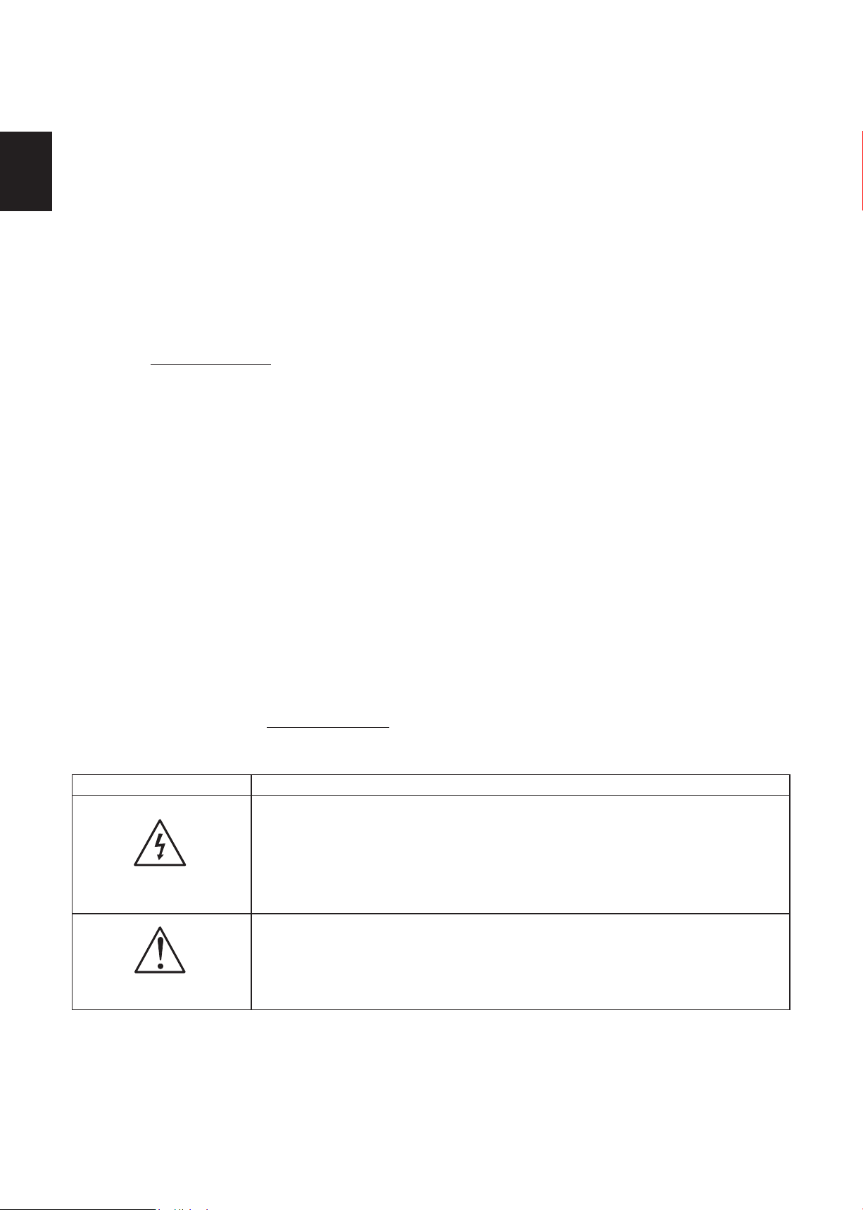
SYMBOL SYMBOL DEFINITION
DANGEROUS VOLTAGE: The lightning flash with arrowhead
symbol, within an equilateral triangle, is intended to alert the user to
the presence of uninsulated “dangerous voltage” within the product’s
enclosure that may be of sufficient magnitude to constitute a risk of
electrical shock to persons.
INSTRUCTIONS: The exclamation point within on
equilateral triangle to alert the User to the presence of
important operating and maintenance (servicing)
instruction In the literature accompanying the appliance.
Apparatus shall not be exposed to dripping or splashing and no objects filled with liquids, Such as
vases, shall be placed on the apparatus.
Caution - Danger of explosion if battery is incorrectly replaced. Replace only with the same or
equivalent type.
1
Page 3
2
English
English
Hg
FOR YOUR SAFETY
Before operating the TV please read this manual thoroughly. This manual should be retained for future
reference.
FCC Class B Radio Frequency Interference Statement
WARNING:
(FOR FCC CERTIFIED MODELS)
NOTE:
device, pursuant to Part 15 of the FCC Rules. These limits are designed to provide reasonable
protection against harmful interference in a residential installation. This equipment generates, uses and
can radiate radio frequency energy, and if not installed and used in accordance with the instructions,
may cause harmful interference to radio communications. However, there is no guarantee that
interference will not occur in a particular installation. If this equipment does cause harmful interference
to radio or television reception, which can be determined by turning the equipment off and on, the user
is encouraged to try to correct the interference by one or more of the following measures:
1. Reorient or relocate the receiving antenna.
2. Increase the separation between the equipment and receiver.
3. Connect the equipment into an outlet on a circuit different from that to which the receiver is
4.
This equipment has been tested and found to comply with the limits for a Class B digital
connected.
Consult the dealer or an experienced radio/TV technician for help.
NOTICE
1. The changes or modifications not expressly approved by the party responsible for compliance could
void the user's authority to operate the equipment.
2. Shielded interface cables and AC power cord, if any, must be used in order to comply with the
emission limits.
3. The manufacturer is not responsible for any radio or TV interference caused by unauthorized
modification to this equipment. It is the responsibilities of the user to correct such interference.
WARNING:
To prevent fire or shock hazard, do not expose the TV to rain or moisture. Dangerously high voltages
are present inside the TV. Do not open the cabinet. Refer servicing to qualified personnel only.
SAFETY: Lamp Disposal
LAMP(S) INSIDE THIS PRODUCT CONTAIN MERCURY AND MUST BE RECYCLED OR
DISPOSED OF ACCORDING TO LOCAL, STATE OR FEDERAL LAWS. FOR MORE INFORMATION,
CONTACT THE ELECTRONIC INDUSTRIES ALLIANCE AT WWW.EIAE.ORG.
Page 4
English3English
PRECAUTIONS AND REMINDERS
1
2
3
4
5
6
7
8
9
0
1
2
3
4
5
6
7
8
9
0
1
2
3
4
5
6
7
8
9
0
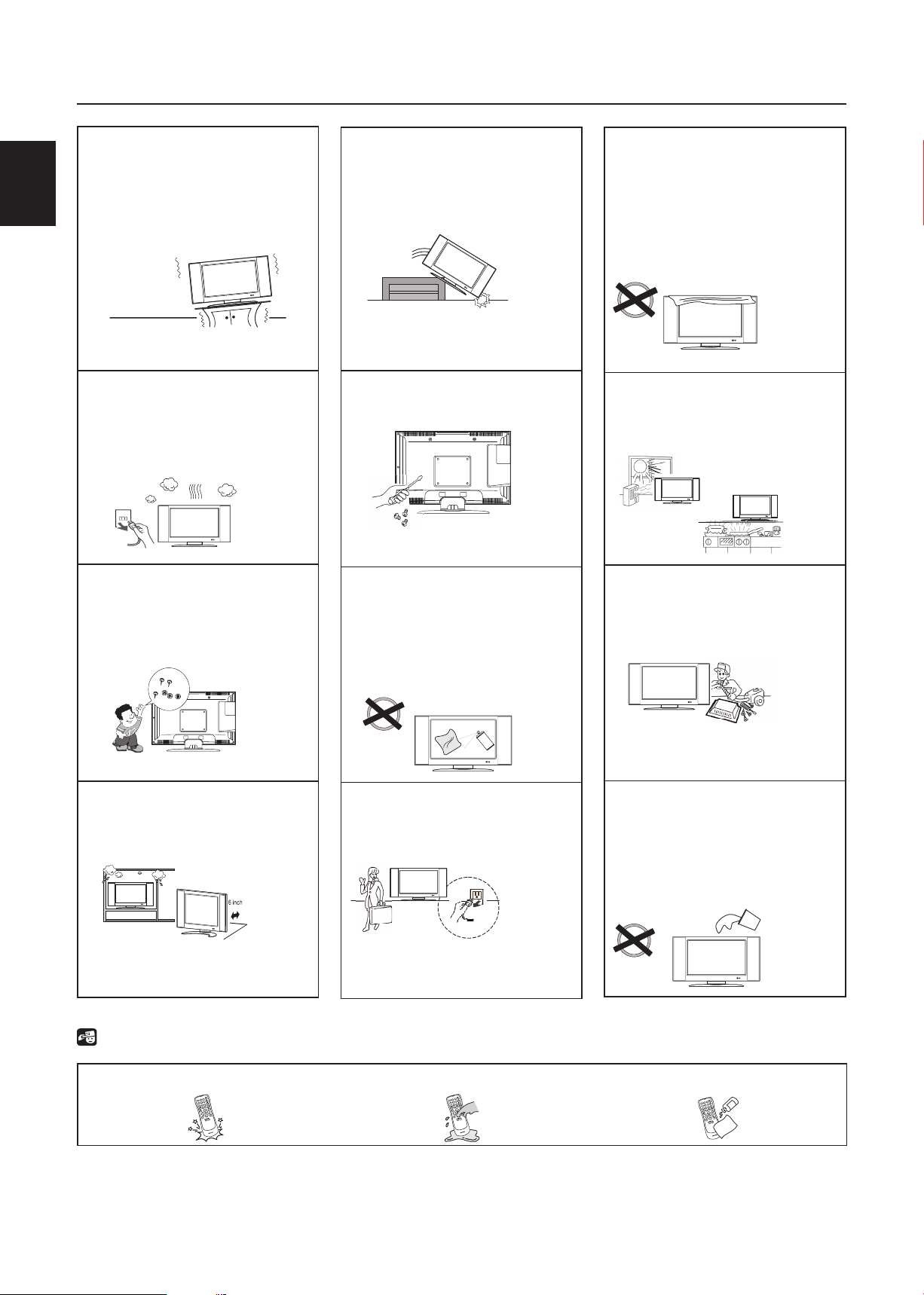
Place unit on even surfaces.
Unplug immediately if other
foreign materials are put
inside TV box or if the TV
fell down.
Do not cover or block
any vents and openings.
Inadequate ventilation
may shorten the life of
the display unit and cause
overheating.
Unplug immediately if is
malfunction like no picture,
no video/audio,smoke and
Prohibit/Avoid opening TV
cabinet
Avoid direct sunlight, dusty,
high humidity and smoky
areas
.
bad odor from TV.
Don't throw any object
inside the TV box like
metals or other flammable
materials.
Don't place the TV in
confined spaces or in a box
when using it.
Remember to unplug the
AC cord from the AC outlet
before cleaning. Do not use
liquid cleaners or aerosol
cleaners to clean the display.
Make sure to unplug the
unit when not in use for a
long period of time (days).
Call service personnel to
clean the internal part of
the TV once a year.
Do not place the display
near water, such as bathtub,
washbasin, kitchen sink
laundry tub, swimming pool
or in a damp basement.
Notice for Remote Controller
Avoid Dropping
Avoid Liquids
Avoid Aerosol Cleaners
Page 5

4
English
English
IMPORTANT SAFETY INSTRUCTIONS
Read before operating equipment
1. Read these instructions.
2. Keep these instructions.
3. Heed all warnings.
4. Follow all instructions.
5. Do not use this apparatus near water.
6. Clean only with a dry cloth.
7. Do not block any of the ventilation openings. Install in accordance with the manufacturers
instructions.
8. Do not install near any heat sources such as radiators, heat registers, stoves, or other
apparatus (including amplifiers) that produce heat.
9. Do not defeat the safety purpose of the polarized or grounding type plug. A polarized plug
has two blades with one wider than the other. A grounding type plug has two blades and
third grounding prong. The wide blade or third prong is provided for your safety. When the
provided plug does not fit into your outlet, consult an electrician for replacement of the
obsolete outlet.
10. Protect the power cord from being walked on or pinched particularly at plugs, convenience
receptacles, and the point where they exit from the apparatus.
11. Only use attachments/accessories specified by the manufacturer.
12. Use only with a cart, stand, tripod, bracket, or table specified by the manufacturer, or sold
with the apparatus. When a cart is used, use caution when moving the cart/apparatus
combination to avoid injury from tip-over.
13. The TV should be operated only from the type of power source indicated on the label. If you
are not sure of the type of power supplied to your home, consult your dealer or local power
company.
14. Unplug this apparatus during lightning storms or when unused for long periods of time.
15. Refer all servicing to qualified service personnel. Servicing is required when the apparatus
has been damaged in any way, such as power-supply cord or plug is damaged, liquid has been
spilled or objects have fallen into apparatus, the apparatus has been exposed to rain or
moisture, does not operate normally, or has been dropped.
16. This product may contain lead or mercury. Disposal of these materials may be regulated due to
environmental considerations. For disposal or recycling information, please contact your local
authorities or the Electronic Industries Alliance: www.eiae.org
17. Damage Requiring Service – The appliance should be serviced by qualified service personnel
when:
A. The power supply cord or the plug has been damaged; or
B. Objects have fallen, or liquid has been spilled into the appliance; or
C. The appliance has been exposed to rain; or
D. The appliance does not appear to operate normally or exhibits a marked change in
performance; or
E. The appliance has been dropped, or the enclosure damaged.
Page 6
English5English
18. Tilt/Stability – All televisions must comply with recommended international global safety
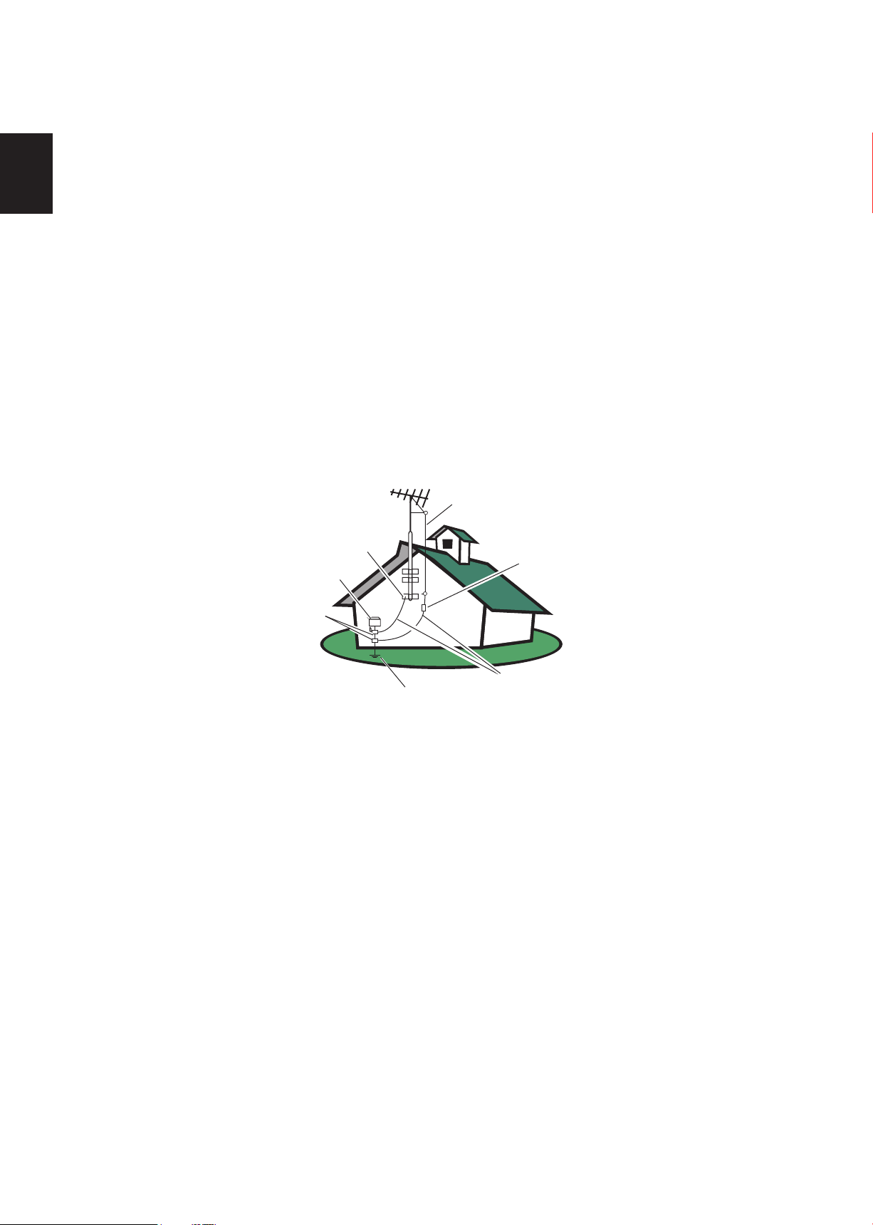
ANTENNA
ANTENNA DISCHARGE UNIT
GROUNDING CONDUCTORS
POWER SERVICE GROUNDING ELECTRODE SYSTEM
GROUND CLAMPS
ELECTRIC SERVICE E QUIPMENT
GROUND CLAMP
standards for tilt and stability properties of its cabinets design.
Do not compromise these design standards by applying excessive pull force to the front,
●
or top, of the cabinet, which could ultimately overturn the product.
Also, do not endanger yourself, or children, by placing electronic equipment/toys on the
●
top of the cabinet. Such items could unsuspectingly fall from the top of the set and cause
product damage and/or personal injury.
19. Wall or Ceiling Mounting – The appliance should be mounted to a wall or ceiling only as
recommended by the manufacturer.
20. Power Lines – An outdoor antenna should be located away from power lines.
21. Outdoor Antenna Grounding – If an outside antenna is connected to the receiver, be
sure the antenna system is grounded so as to provide some protection against voltage surges
and built up static charges.
Section 810 of the National Electric Code, ANSI/NFPA No. 70-1984, provides information
with respect to proper grounding of the mats and supporting structure grounding of the
lead-in wire to an antenna-discharge unit, size of grounding connectors, location of antennadischarge unit, connection to grounding electrodes and requirements for the grounding
electrode. See Figure below.
22. Objects and Liquid Entry – Care should be taken so that objects do not fall and liquids
PACKAGE CONTENTS
EXAMPLE OF ANTENNA GROUNDING AS PER NATIONAL ELECTRICAL CODE
Note to the CATV system installer: This reminder is provided to call the CATV system
installer’s attention to Article 820-40 of the NEC that provides guidelines for proper
grounding and, in particular, specifies that the cable ground shall be connected to the
grounding system of the building, as close to the point of cable entry as practical.
Please, make sure to connect the power plug to the wall outlet socket after connecting the
TV to the adapter!
are not spilled into the enclosure through openings.
AOC
●
●
●
●
●
●
●
●
L47H861 TV unit
Remote Control
Two (AAA) Batteries for the Remote Control
Base
Four screws (to attach the Base to the stand)
Power Cord
User Manual
Quick Setup Guide
Page 7
6
English
English
PREPARATION
IMPORTANT: Do not apply pressure to the screen display area which may compromise the
integrity of the display. The manufacturer’s warranty does not cover user abuse or improper
installations.
ATTACHING THE BASE
IMPORTANT: The Base of the HDTV must be assembled prior to usage.
1. Place TV unit face down on a soft and flat surface
(blanket, foam, cloth, etc.) to prevent any damage
to the HDTV.
2. Carefully align and insert the Base to the stand.
3. Gently push the Base towards the HDTV until
the locking mechanism locks into place.
4. Insert the provided screws to the bottom of the
base.
5. Use a screwdriver to tighten the Base to the
stand.
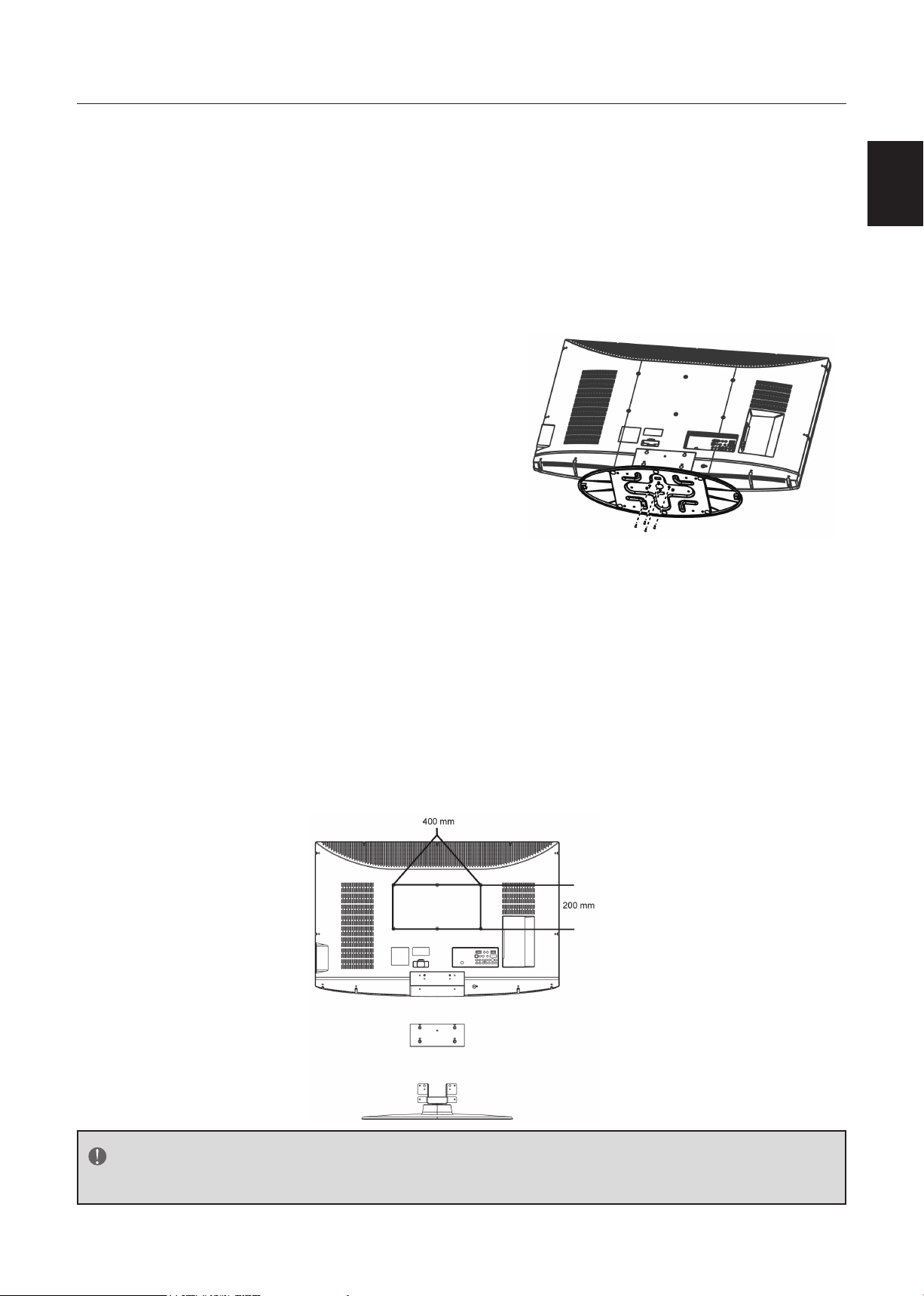
PREPARING YOUR LCD HDTV FOR WALL MOUNTING
We suggest that you keep your TV at least 2.36 inches (60 mm) from the wall to prevent cable
interference.
Before mounting your TV on the wall, you need to remove the base.
To attach a wall mount bracket to your TV:
1 Remove the two T4 and four M4 screws holding your TV to the stand.
2 Secure the wall mount bracket to the back of your TV using six M6 screws, as indicated in
the illustration.
NOTE
400mmx200mm wall mount bracket & M6 screws not included.
Page 8
English7English
POWER
VIDEO COMP PC/HDMI TV
Power Key
Please make sure to connect the power plug
Min
1 m
to the wall outlet socket after connecting the
TV to the power cord!
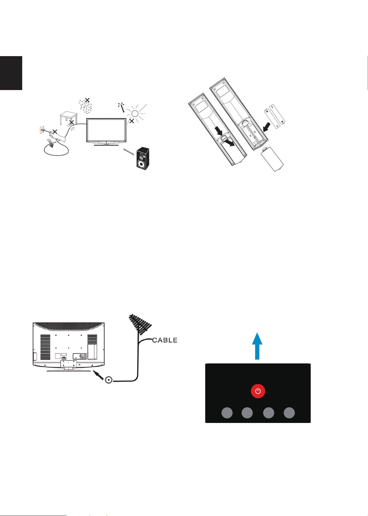
1. Install the base stand; place the TV
on a solid surface.
Ensure that the TV is placed in a position
to allow free flow of air. Do not cover the
ventilation openings on the back cover.
To prevent any unsafe situations, no naked
flame sources, such as lighted candles,
should be placed on or in the vicinity.
Avoid heat, direct sunlight and exposure
to rain or water. The equipment shall not
be exposed to dripping or splashing.
2. Connect the antenna cable or CATV cable
to the aerial socket ANT IN 75Ω at the
back of the TV set.
3. Remote control:
Remove the cover of the battery
compartment. Insert the 2 batteries
supplied (Type AAA 1.5V).
4. Power:
Insert the power cord in the wall socket
with AC power supply. You can see LED
states at the front panel. If the LED color
is Blue, means the TV set is power on. If
the LED color is Red, which means this TV
set is in standby state.
5. Turn the TV on:
Press the POWER key on the Remote
control or the Front panel control knobs.
The TV will be turned on in a minute with
display on the screen.
Page 9
8
English
English
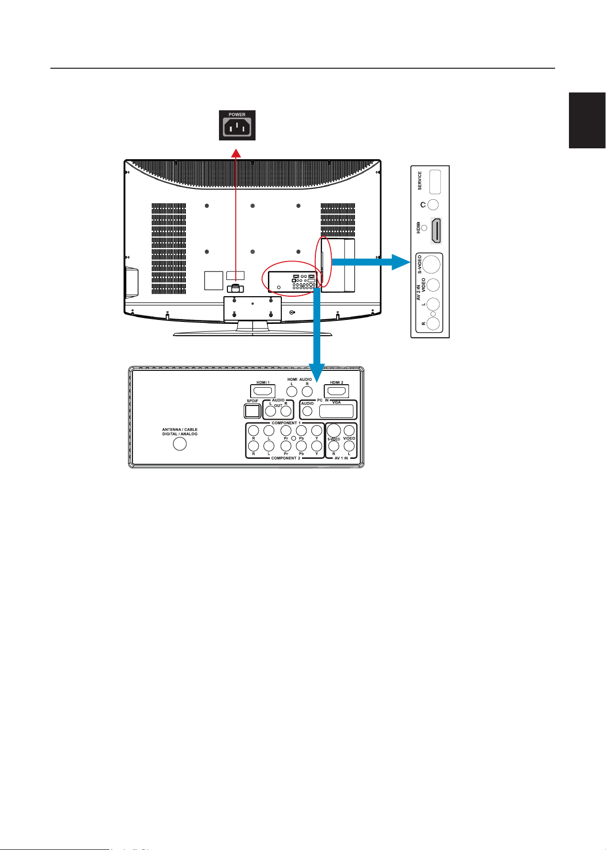
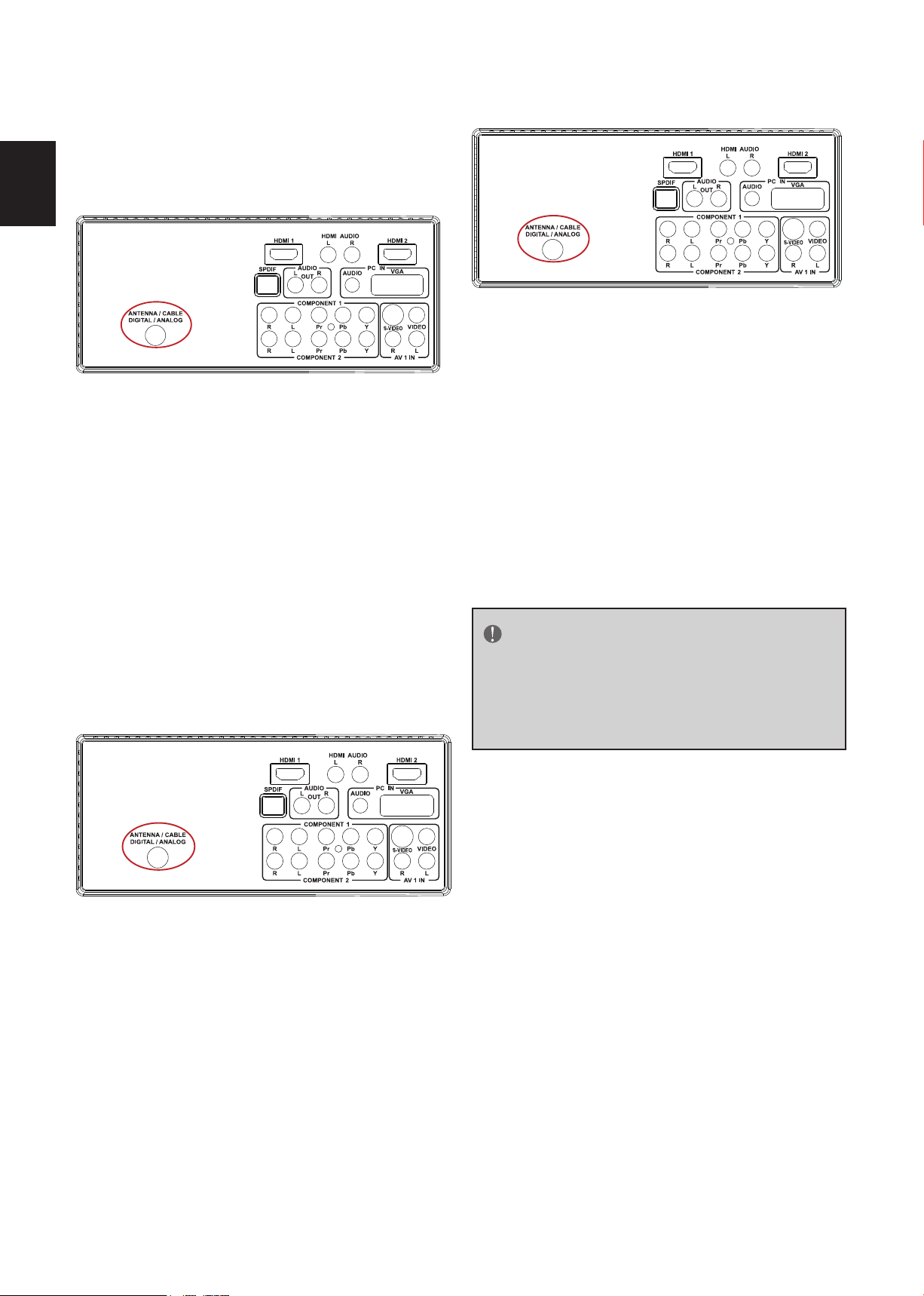
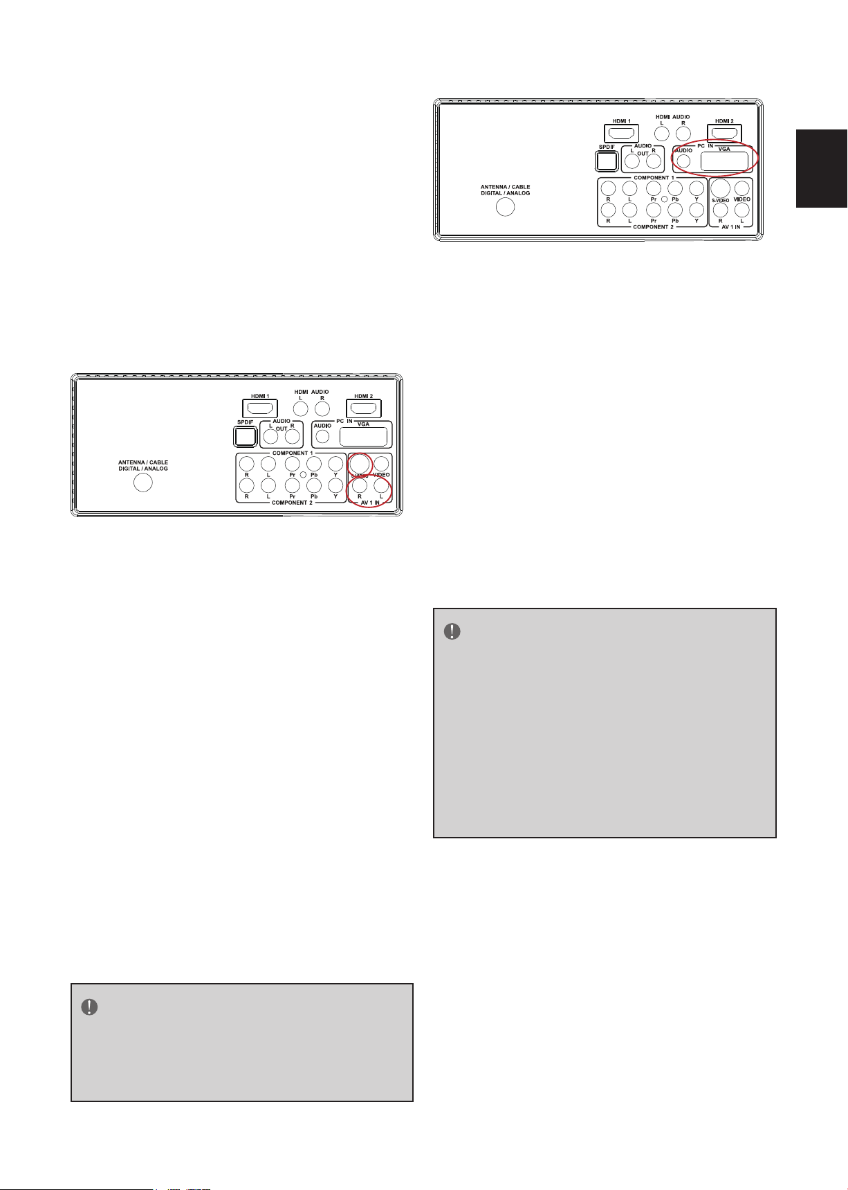
PERIPHERAL CONNECTION GUIDE
3
AC POWER
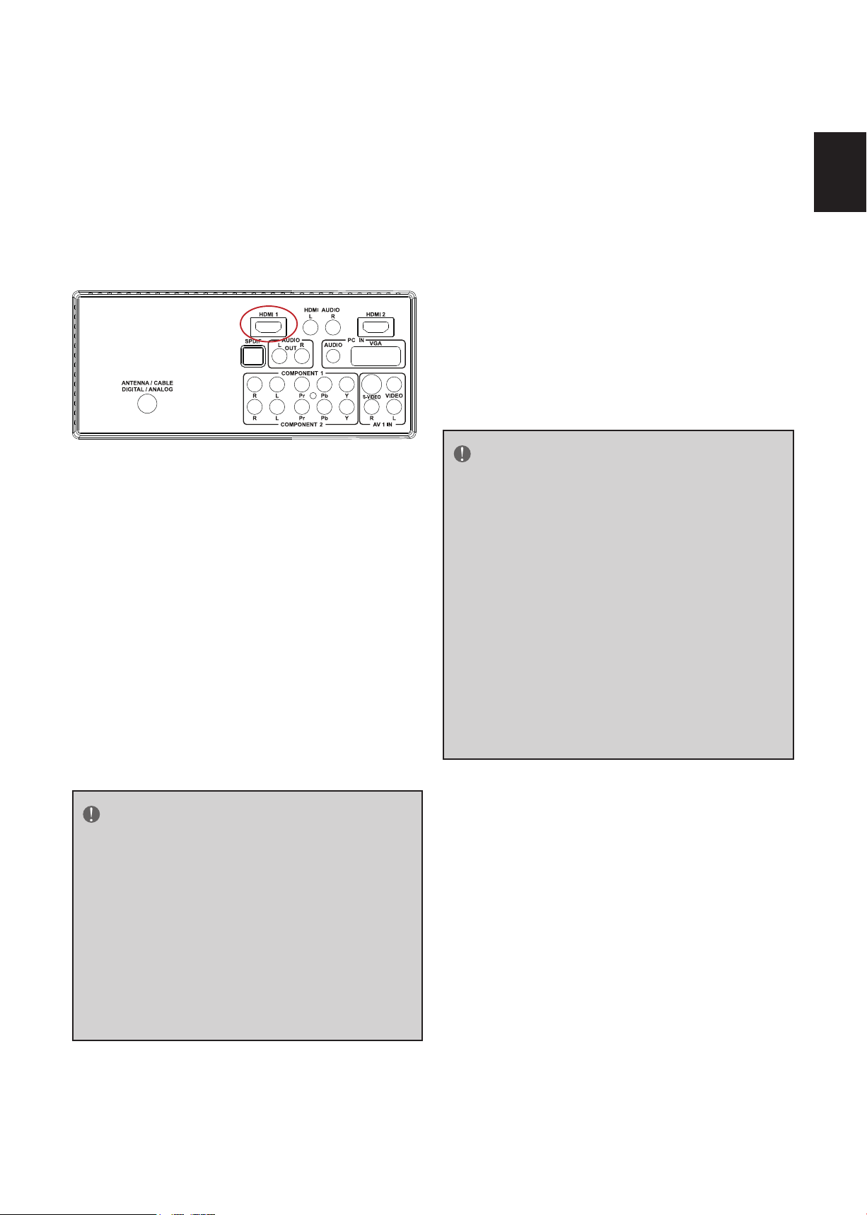
1. HDMI – Connect the primary source for digital video such as a DVD multimedia player or
set top box through this all digital connector. The white color band on the rear of the TV
indicates this connection.
2. PC IN – Connect the video and audio cables from a computer here.
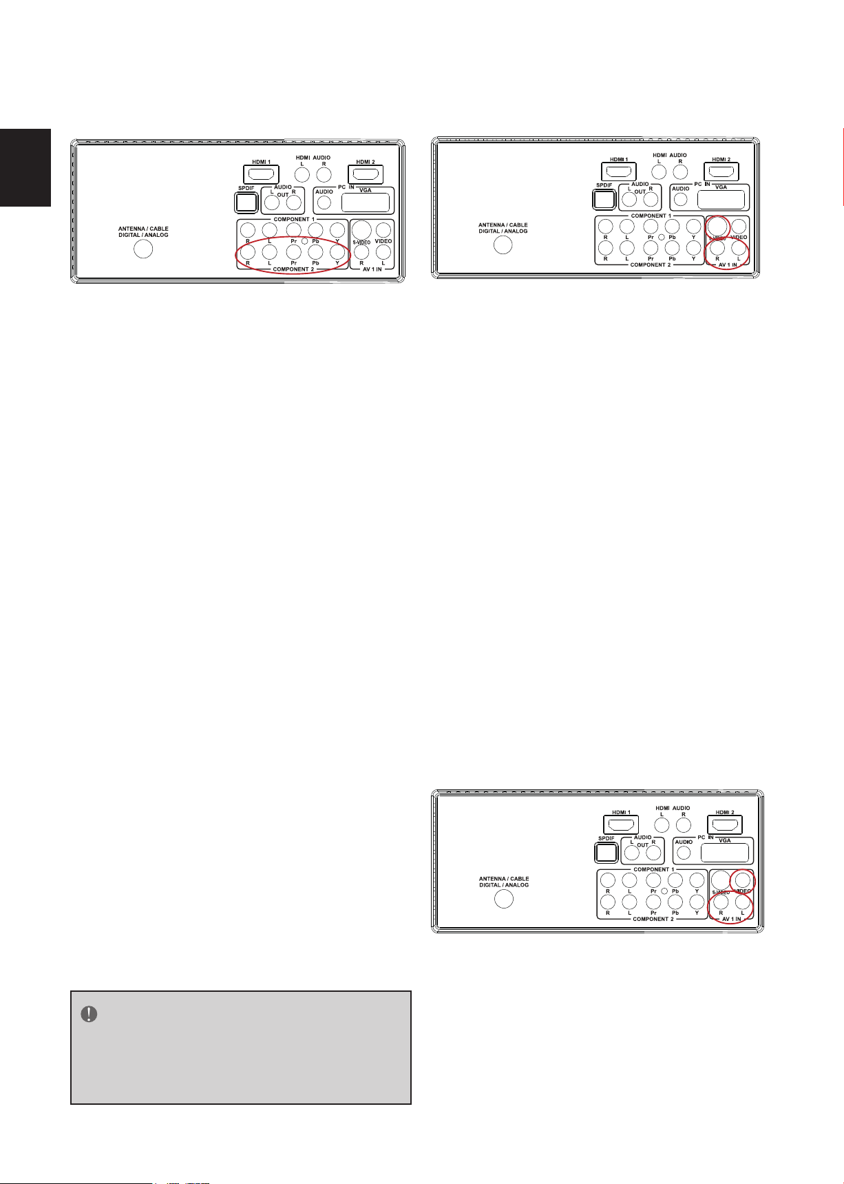
3. AV/S-VIDEO IN – Connect the primary source for composite video devices, such as a
VCR or video game. Use the white and red connectors to connect the external audio from
the same source. The signal being carried by the S-Video cable and connector, if connected,
will take priority over the Video RCA connector (yellow connector).
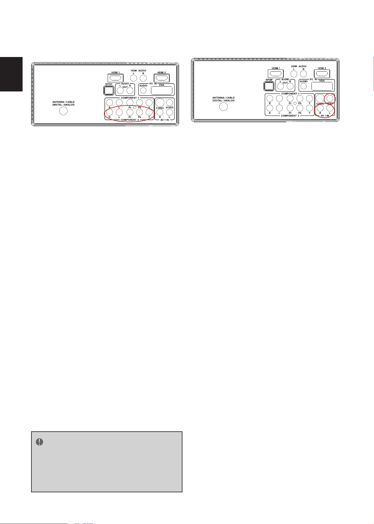
4. COMPONENT (YPb/CbPr/Cr with Audio L/R) – Connect the primary source for
component video devices such as a DVD Player or set top box here. From left to right, use
red for Pr, blue for Pb, green for Y, red for right audio (R) and white for left audio (L) inputs.
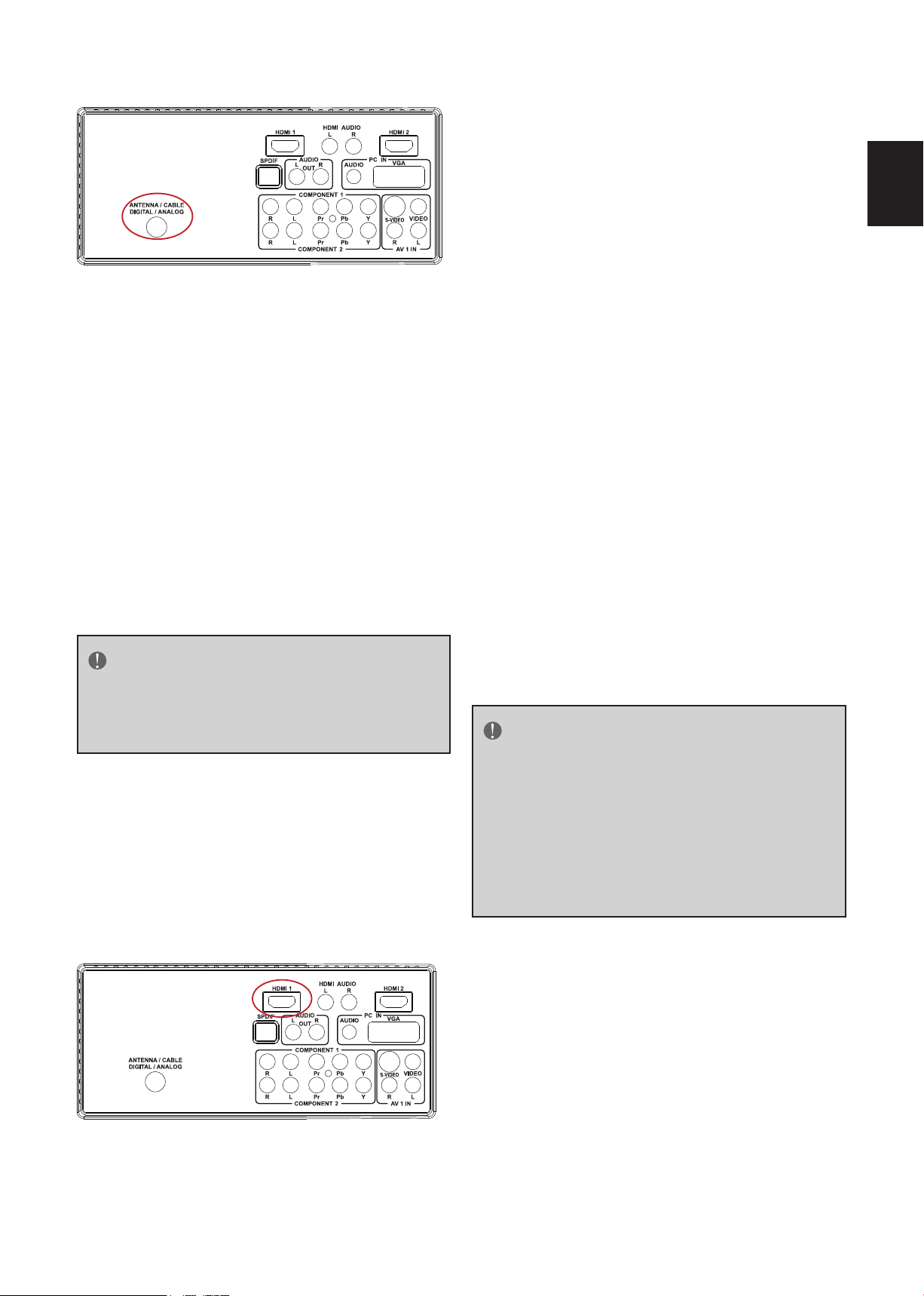
5. DTV – Connect to an antenna or digital cable (out-of-the-wall, not from Cable Box) for
Digital TV.*
6. SPDIF (Optical Digital Audio Out) - When a digital audio signal is associated with the
input selected for viewing, the digital audio will be available on this SPDIF connection to
your home theater system.
Once your equipment is connected, use the following procedure to view the input signal:
Press the source button on the remote controller to select the relevant source to view. (ex: Press VIDEO
button to select “Composite Rear” if you have connected a video recorder to Composite Rear socket.)
Page 10
English9English
OPERATING INSTRUCTIONS
1
2
3
5
6
4
7
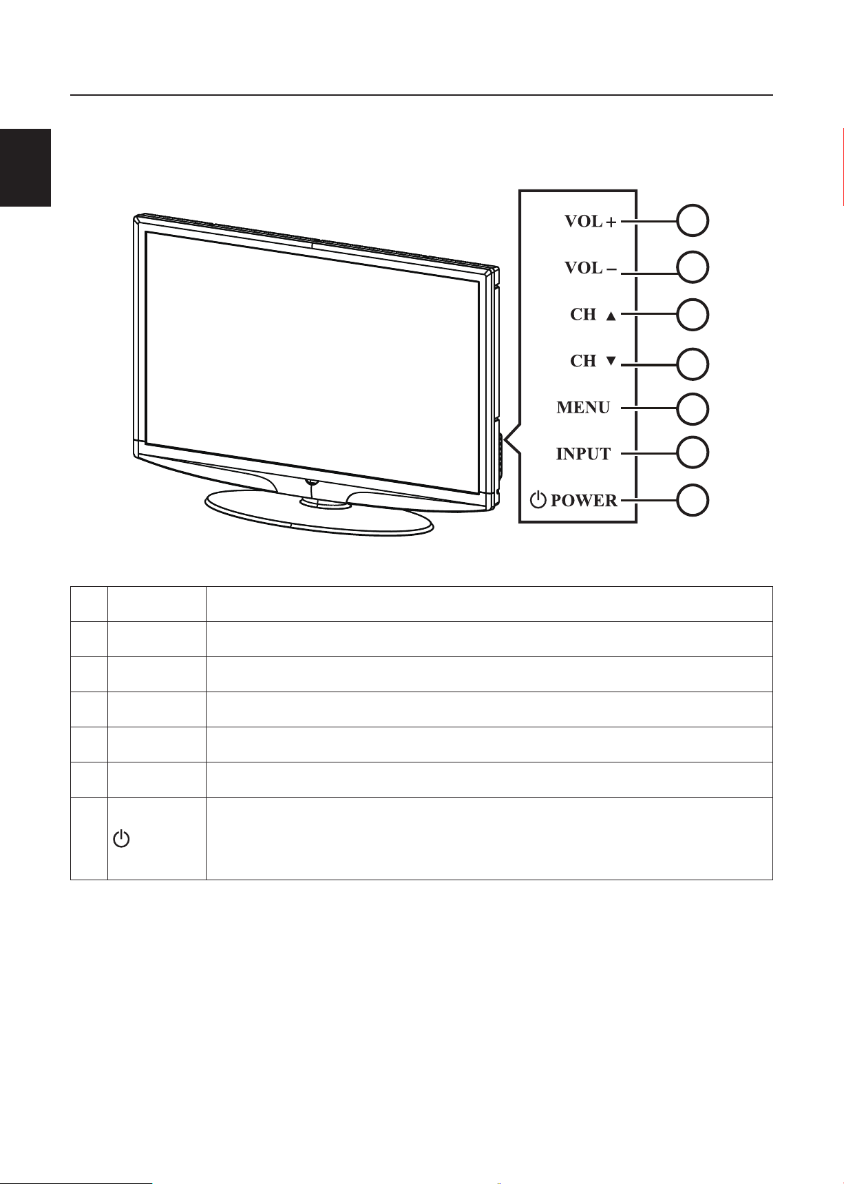
TO USE THE FRONT PANEL CONTROL
1 VOL + VOL +: Press to increase the sound volume level.
2. VOL - VOL - : Press to decrease the sound volume level.
3. CH
4. CH
5. MENU Menu key: Press to open or exit the OSD menu.
6. INPUT Source key: Press to select the input source.
7.
▲
▼
POWER
CH : Press to select the next higher Program number.
▲
CH : Press to select the next lower Program number.
▼
Power key: Press to turn on / off (standby) the TV set. (Please re-turn
on TV after the Power-ON status LED had changed to the Red color and
finished flashing.)
Page 11
10
English
English
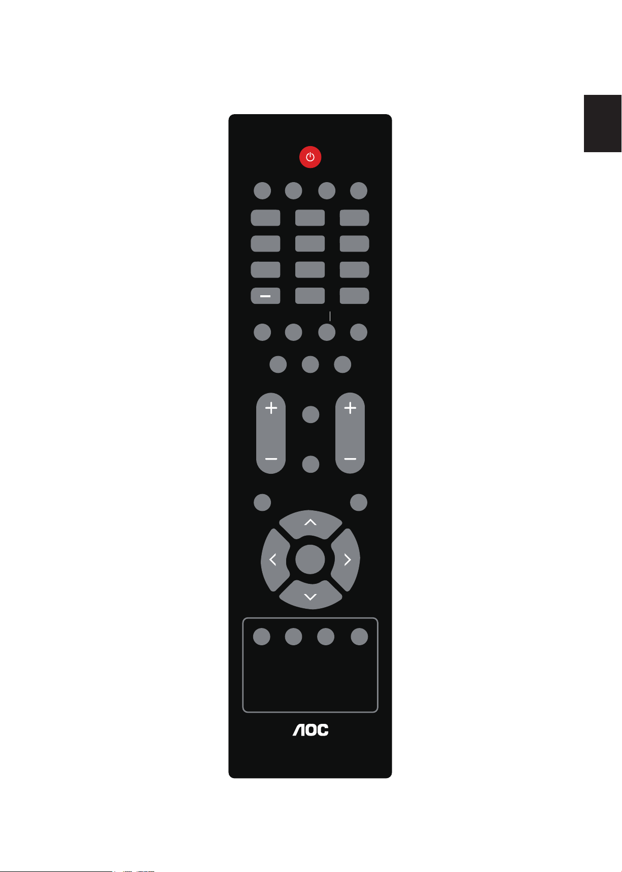
TO USE THE REMOTE CONTROL
POWER
VIDEO
1 2 3
4 5 6
7 8 9
0
PRE CH
COMP PC/HDMI TV
SLEEP
FAV SOURCE
MUTE
MENU EXIT
ENTER
V-CHIP
VIDEO ADJ AUDIO ADJ
CC
DISPLAY
VOLCH
EPG
FREEZE MTS SAP
WIDE
RL57A
POWER
Press to power ON/OFF
(standby) TV.(Note:1.TV is
never completely power off.
unless physically unplugged.
2.Press to turn on TV after
the power on status, LED had
changed to the red color and
stopped flashing.)
VIDEO
Press repeatedly to choose
S-Video/Composite source
mode.
COMP
Press repeatedly to choose
Component source mode.
PC/HDMI
Press repeatedly to choose VGA
or HDMI source mode.
TV
Press to choose ATSC/NTSC
TV source mode.
0 ~ 9 /- number
Press to enter TV channel
number to select channel (Press
‘-’ to choose the sub-channel).
SLEEP
Press to set a time period (off/5
min /10 min /15 min /30min/45
min /60min/90min/120 min
/180 min /240 min)after which
the TV should switch itself to
standby mode.
FREEZE
Press to freeze the displayed
picture.
CH-/ CH +
Press + or - to browse through
the TV channels.
MENU
Press to open or exit menu.
“<”,“>”,“<”,“>”,“ENTER
Press to adjust the various
function items on the menu.
MTS/SAP
Press to activate the NTSC TV
sounds, such as: Stereo, SAP or
Mono tone, and languages of
DTV.
WIDE
Press to choose the display
aspect as: Normal, Wide, Zoom
or Cinema mode.
SOURCE
Press repeatedly to choose the
various input sources.
EPG
This function is not supported.
MUTE
Switch the sound ON/OFF
DISPLAY
Press to show the information
about the input source,TV
channel,display resolution and
current time.
VOL- / VOL+
Press + or - to adjust the
volume.
Exit
Press to exit menu or OSD.
V-CHIP
Press to lock / unlock Parental
Control temporarily. (After
setting the restricted table of
MPAA or TV Rating.)
VIDEO ADJ
Press to choose the Brightness
or Contrast adjustment.
AUDIO ADJ
Press to choose Bass and Treble.
CC
Press repeatedly to change
the closed caption type as CC
ON/CC OFF/CC ON WHEN
MUTE.
FAVORITE
Press to toggle the Favorite/
Normal mode.
PREV CH
Press to display the previous
channel
Page 12
English11English
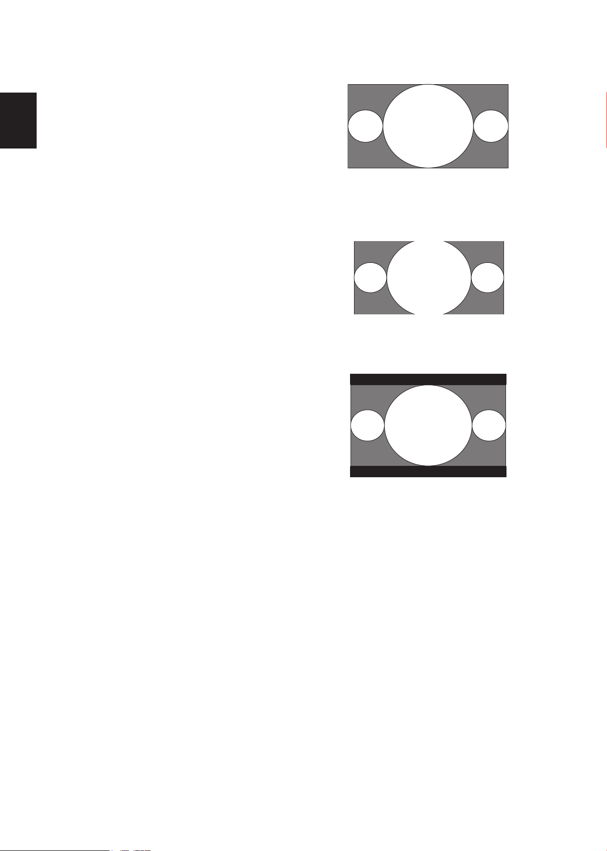
VIEWING MODELS ILLUSTRATIONS
Normal Mode on 16:9 Display screen
The original content would be at the center
of the screen.
Wide Mode on 16:9 Display screen
The original content in this mode has to fill
the entire width of the display horizontally.
Wide Mode on 16:10 Display screen
Wide1 and Wide2 are applied:
Wide1: The original content would fill the
full screen while the proper ratio of
16:9 content is still maintained. Little
cropping of the content on the sides
is necessary.
Wide2: The original content would fill
the width of the screen while the
proper ratio of 16:9 content is still
maintained. Small black bars are
added.
Page 13
12
English
English
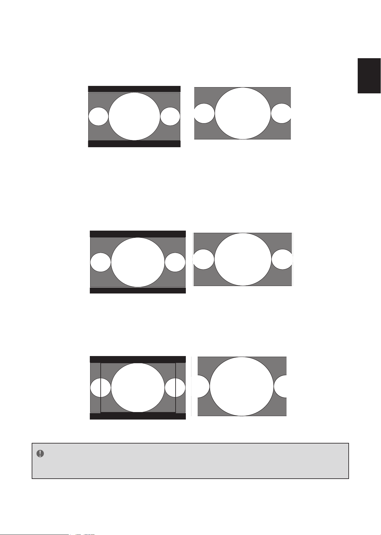
ZOOM Mode on 16:9 Display screen
For those wide format images which are originally programmed into 4:3 frames with top and
bottom black bars, this mode would stretch the image in both width and heigh for full display
with active data.
16:9 image in 4:3 frame
Same image in ZOOM mode
ZOOM Mode on 16:10 Display screen
For those wide format images which are originally programmed into 4:3 frames with top and
bottom black bars, this mode would stretch the image in both width and heigh for full display
with active data. Little cropping on sides is necessary for full display.
16:9 image in 4:3 frame
CINEMA Mode on 16:9 or 16:10 Display screen
This mode is applied to view 2.35:1 format content on 16:9 displays. Cropping on both right
and left sides to keep the image ratio undistorted for users.
Same image in ZOOM mode
NOTE
AOC L47H861 has 4 picture formats: Normal, Wide, Zoom and Cinema.
Page 14
English13English
CONNECTING EQUIPMENT
Coaxial (RF)
Using Your Antenna or Digital Cable for
.
DTV
1. Turn off the power to the HDTV.
2. Connect the coaxial (RF) connector from
your antenna or digital cable (out-ofthe-wall, not from the Cable Box) to the
ANTENNA/CABLE DIGITAL/ANALOG
connector.
3. Turn on the power to the HDTV.
4. Select DTV using the INPUT (SOURCE)
button on the remote, side of the HDTV
or directly by pressing the TV button on
the Remote Control.
Using Your Antenna or Cable for DTV
Using the Antenna or Cable for your
VCR
1. Turn off the power to the HDTV and VCR.
2. Connect the “Output to TV”, “RF Out”
or “Antenna Out” connector on the rear
of your VCR to the ANTENNA/CABLE
DIGITAL/ANALOG connector at the rear
of the HDTV.
3. Turn on the power to the HDTV and VCR.
4. Select TV using the INPUT (SOURCE)
button on the remote, side of the HDTV
or directly by pressing the TV button on
the Remote Control.
NOTE
If you have an off-air antenna or cable TV,
connect it to the “Antenna In” connector
.
on the rear of your VCR.
1. Turn off the power to the HDTV.
2. Connect the coaxial (RF) connector from
your antenna or cable (out-of-the-wall, not
from the Cable Box) to the ANTENNA/
CABLE DIGITAL/ANALOG connector at
the rear of the HDTV
3. Turn on the power to the HDTV.
4. Select TV using the INPUT (SOURCE)
button on the remote, side of the HDTV
or directly by pressing the TV button on
the Remote Control.
Page 15
14
English
English
Connecting Your HDTV Set-Top Box
For HDTV Set-Top Boxes with DVI
Using HDMI
HDTV Set-Top Boxes that have a HDMI digital
interface should be connected to the HDMI
input of the LCD HDTV for optimal results.
1. Turn off the power to the HDTV and
HDTV Set-Top Box.
2. Using a HDMI-DVI cable, connect the DVI
end to your HDTV Set-Top Box and the
HDMI end to the HDMI Input at the rear
Connecting your HDTV Set-Top Box
(Best)
of the HDTV.
3. Turn on the power to the HDTV and
HDTV Set-Top Box.
4. Select HDMI using the INPUT (SOURCE)
button on the remote, side of the HDTV,
or directly by pressing the HDMI button
on the Remote Control.
NOTE
The HDMI input on the HDTV supports
1. Turn off the power to the HDTV and
HDTV Set-Top Box.
2. Connect a HDMI cable to the HDMI
output of your HDTV Set-Top Box and the
other end to the HDMI Input at the rear
of the HDTV.
3. Turn on the power to the HDTV and
HDTV Set-Top Box.
High-bandwidth Digital Content Protection
(HDCP). HDCP encrypts the transmission
between the video source and the digital
display for added security and protection.
Refer to your HDTV Set-Top Box user
manual for more information about the
video output requirements of the product
or consult your cable or satellite operator.
4. Select HDMI using the INPUT (SOURCE)
button on the remote, side of the HDTV,
or directly by pressing the HDMI button
on the Remote Control.
NOTE
The HDMI input on the HDTV supports
High-bandwidth Digital Content Protection
(HDCP). HDCP encrypts the transmission
between the video source and the digital
display for added security and protection.
Refer to your HDTV Set-Top Box user
manual for more information about the
video output requirements of the product
or consult your cable or satellite operator.
The DVI to HDMI connection provides
video only. Connection to an alternate
audio player is required for audio.
Page 16
English15English
Using Component Video
Connecting your HDTV Set-Top Box
(Better):
Connecting Your Basic Set-Top Box
Using Composite Video
1. Turn off the power to the HDTV and
HDTV Set-Top Box.
2. Connect the Pr (red color) connector
on your HDTV Set-Top Box to the
corresponding Pr (red color) connector in
the Component group.
3. Connect the Pb (blue color) connector
on your HDTV Set-Top Box to the
corresponding Pb (blue color) connector
in the Component group.
4. Connect the Y (green color) connector
on your HDTV Set-Top Box to the
corresponding Y (green color) connector
in the Component group.
5. Using an audio cable (red and white
connectors), connect the cable to the
audio output connectors associated with
the Component output on your HDTV
Set-Top Box and connect the other end to
the audio connectors associated with the
Component.
1. Turn off the power to the HDTV and SetTop Box.
2. Using an AV Cable, connect the Video
(yellow color) connector on your Set-Top
Box to the corresponding Video (yellow
color) connector in the AV group at the
rear of the HDTV.
3. Using the red and white connectors,
connect the cable to the audio output
connectors associated with the Video
output on your Set-Top Box and connect
the other end to the audio connectors
associated with the AV input at the rear of
the HDTV.
4. Turn on the power to the HDTV and SetTop Box.
5. Select Composite (Video 1) using the
INPUT (SOURCE) button on the remote,
side of the HDTV or directly by pressing
the AV button on the Remote Control.
6. Turn on the power to the HDTV and
HDTV Set-Top Box.
7. Select Component (Video 3) using the
INPUT (SOURCE) button on the remote,
side of the HDTV or directly by pressing
the Component button on the Remote
Control.
NOTE
Refer to your HDTV Set-Top Box user
manual for more information about the
video output requirements of the product
or consult your cable or satellite operator.
Page 17
16
English
English
Using Coax (RF)
2. Connect a HDMI cable to the HDMI
output of your DVD player and the other
end to the HDMI Input at the rear of the
HDTV.
3. Turn on the power to the HDTV and DVD
player.
1. Turn off the power to the HDTV and SetTop Box.
2. Using a Coax (RF) cable, connect one end
to the TV OUT (RF) on your Set Top Box
and the other end to the DTV/TV input at
the rear of the HDTV.
3. Turn on the power to the HDTV and SetTop Box.
4. Select TV using the INPUT (SOURCE)
button on the remote, side of the HDTV
or directly by pressing the TV button
(below the WIDE button) on the Remote
Control.
NOTE
Refer to your Set Top Box user manual
for more information about selecting the
video or RF output of the product.
Connecting Your DVD Player
Using HDMI
DVD players that have a digital interface
such as HDMI (High Definition Multimedia
Interface) should be connected to the HDMI
input of the LCD HDTV for optimal results.
4. Select HDMI using the INPUT (SOURCE)
button on the remote, side of the HDTV
or directly by pressing the HDMI button
on the Remote Control.
For DVD Players with DVI:
1. Turn off the HDTV and DVD player.
2. Using a HDMI-DVI cable, connect the DVI
end to your DVD player and the HDMI
end to the HDMI Input at the rear of the
HDTV.
3. Turn on the power to the HDTV and your
DVD player.
4. Select HDMI using the INPUT (SOURCE)
button on the remote or side of the
HDTV, or directly by pressing the HDMI
button on the Remote.
NOTE
Refer to your DVD player user manual for
more information about the video output
requirements of the product.
The DVI to HDMI connection provides
video only. Connection to an alternate
audio player is required for audio output.
Connecting your DVD Player (Best)
1. Turn off the power to the HDTV and DVD
player.
Page 18
English17English
Using Component Video
Using S-Video (AV)
Connecting your DVD Player (Better)
1. Turn off the power to the HDTV and DVD
player.
2. Connect the Pr (red color) connector on
your DVD player to the corresponding Pr
(red color) connector in the Component
at the rear of the HDTV.
3. Connect the Pb (blue color) connector on
your DVD player to the corresponding Pb
(blue color) connector in the Component
group at the rear of the HDTV.
Connecting your DVD Player (Good):
1. Turn off the power to the HDTV and DVD
player.
2. Connect the S-Video jack on the rear of
your DVD player to the S-Video jack in the
AV group on the rear of the HDTV.
3. Connect an audio cable (white and
red connectors) to the audio output
connectors associated with the S-Video
output on your DVD player and connect
the other end to the audio connectors
associated with the AV input on the rear of
the HDTV.
4. Connect the Y (green color) connector on
your DVD player to the corresponding Y
(green color) connector in the Component
group at the rear of the HDTV.
5. Using an audio cable (red and white
connectors), connect the cable to the
audio output connectors associated with
the Component output on your DVD
player and connect the other end to the
audio connectors associated with the
Component input at the rear of the HDTV.
6. Turn on the power to the HDTV and DVD
player.
7. Select Component using the INPUT
(SOURCE) button on the remote, side
of the HDTV or directly by pressing
the Component button on the Remote
Control.
4. Turn on the power to the HDTV and DVD
player.
5. Select S-Video (Video 2) using the INPUT
(SOURCE) button on the remote, side of
the HDTV, or directly by pressing the AV
button on the Remote Control.
Using Composite (AV) Video
Connecting your DVD Player (Good)
1. Turn off the power to the HDTV and DVD
player.
NOTE
Refer to your DVD player user manual for
more information about the video output
requirements of the product.
2. Connect the Video (yellow color)
connector on your DVD player to the
Video (yellow color) connector in the AV
group.
Page 19
18
English
English
3. Connect the R (red color) and L (white
Connecting to a PC
color) audio connectors on your DVD
player to the corresponding R (red color)
and L (white color) audio input connectors
in the AV group.
4. Turn on the power to the HDTV and DVD
Player.
5. Select Composite (Video 1) using the
INPUT (SOURCE) button on the remote,
side of the HDTV or directly by pressing
the AV button on the Remote Control.
Connecting Your VCR or Video Camera
1. Turn off the HDTV and VCR or Video
Camera.
1. Turn off the power to the HDTV and PC.
2. Connect a 15-pin D-Sub RGB (VGA) cable
to the RGB output of your PC IN and the
other end to the PC input at the rear of
the HDTV.
3. Connect the Audio Out on your computer
to the RGB PC Audio input at the rear of
the HDTV.
4. Turn on the HDTV and PC.
5. Select RGB(PC) using the INPUT
(SOURCE) button on the remote, side of
the HDTV or directly by pressing the PC/
HDMI button on the Remote.
2. Connect the S-Video jack on the rear of
your VCR or Video Camera to the S-Video
jack in the AV group on the rear of the
HDTV.
3. Connect an audio cable (white and red
connectors) cable to the audio output
connectors associated with the S-Video
output on your VCR or Video Camera
and connect the other end to the audio
connectors associated with the AV input
on the rear of the HDTV.
4. Turn on the power to the HDTV and VCR
or Video Camera.
5. Select S-Video (Video 2) using the INPUT
(SOURCE) button on the remote, side of
the HDTV or directly by pressing the AV
button on the Remote Control.
NOTE
For the best picture quality when
connecting a computer through RGB PC,
set your computer timing mode to native
resolution of panel. Please refer to the PC
or graphic card’s user guide for additional
information on how to set the timing
mode and the video output requirements
of the product.
NOTE
Refer to your VCR or Video Camera user
manual for more information about the
video output requirements of the product.
Page 20
English19English
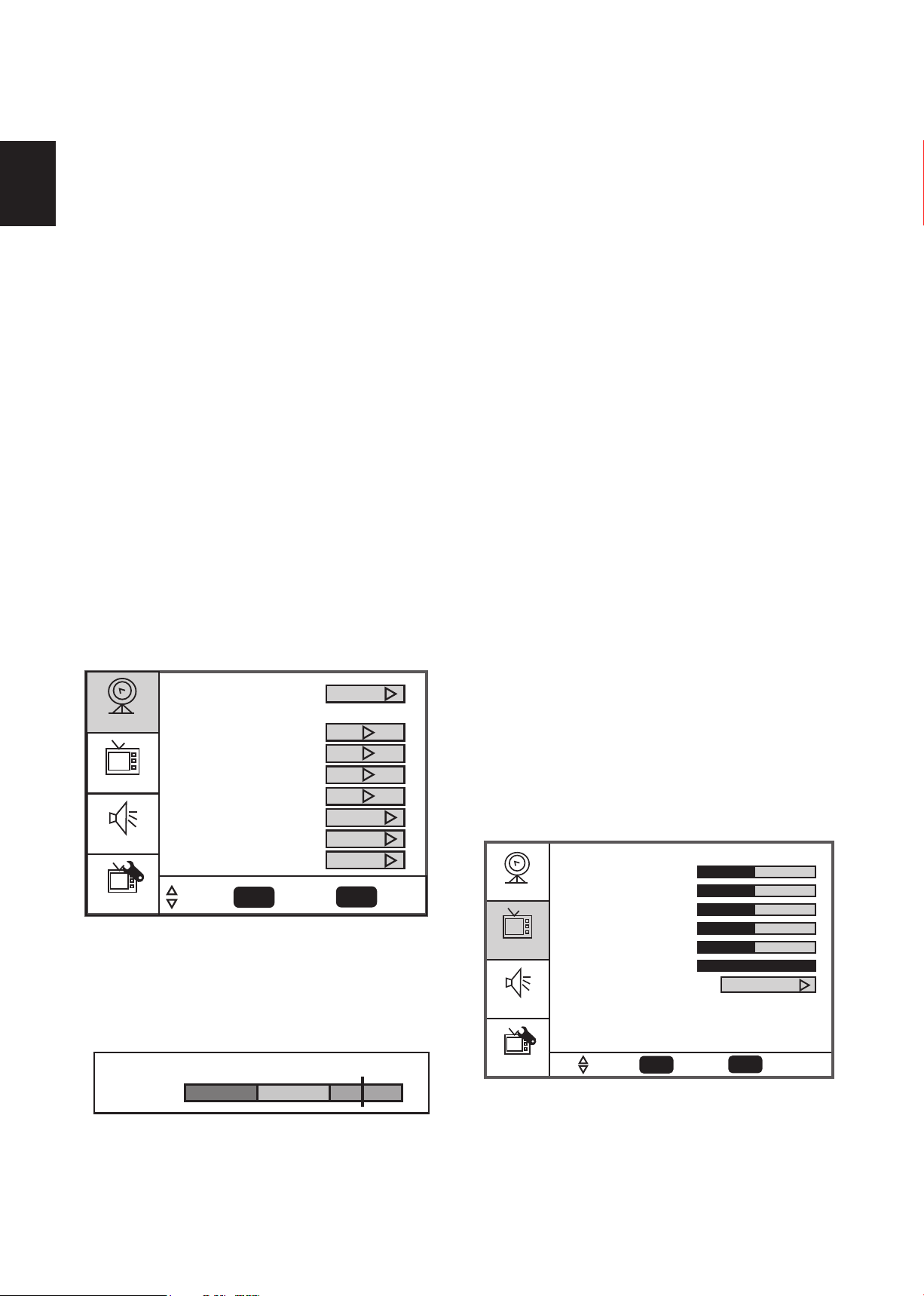
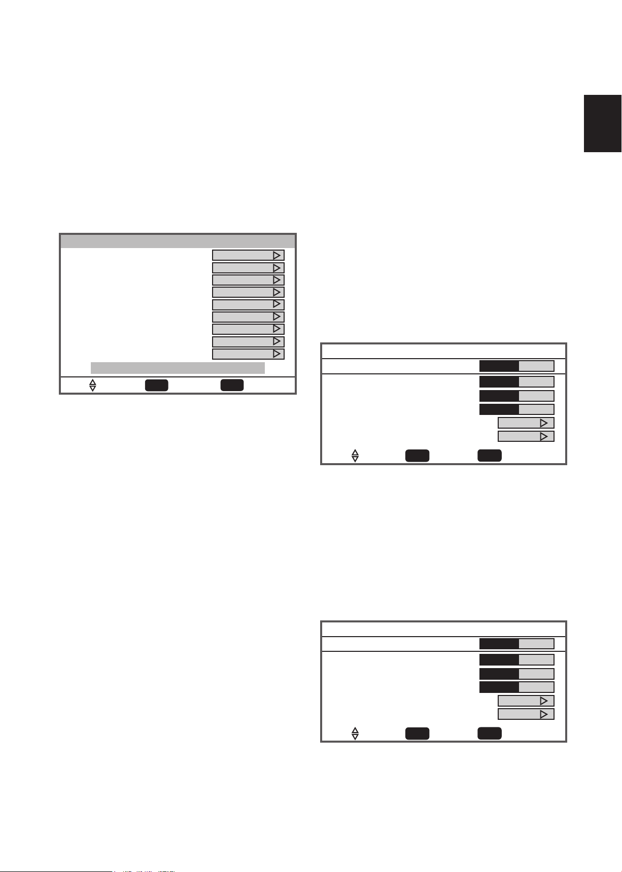
TO USE THE MENUS
Weak
Signal level
Normal Good
95
Setup
Video
Audio
Feature
Enter
To SelectTo Move To Exit
Exit
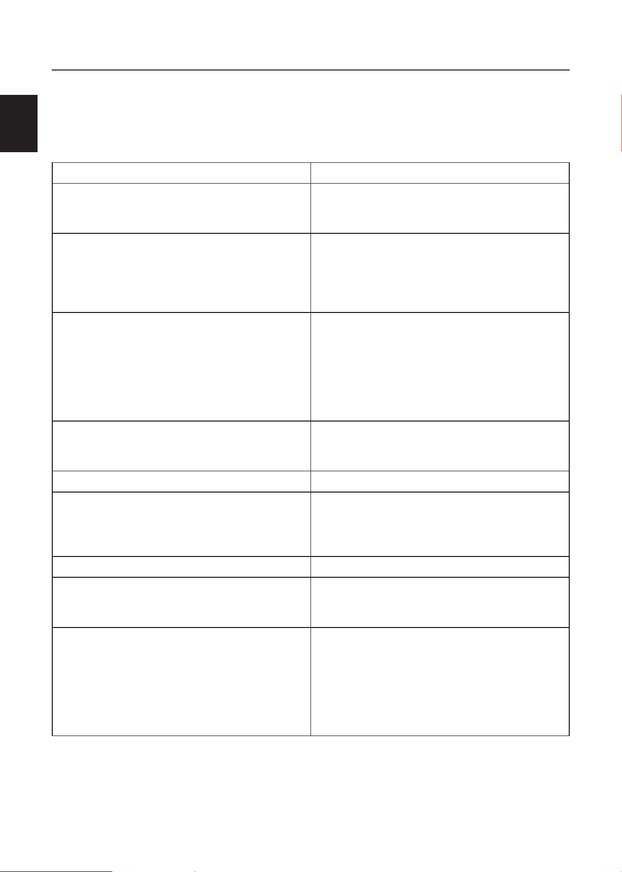
Contrast 50
50
0
50
0
10
Preset
Brightness
Sharpness
Color
Tint
Backlight
Settings
Setup
Video
Audio
Feature
Tuning Band
DTV Signal
Auto Ch Search
Add On Ch Search
Manual Channel Set
Channel Labels
Menu Language
Aspect Ratio
Favorite Channel Mode
Enter
Exit
To SelectTo Move To Exit
Cable
English
Normal
Off
1. Press the MENU button to display the
main menu
2. Use the Cursor Up/Down to select a
menu item.
3. Use the Cursor Left/Right to enter a
submenu.
4. Press the ENTER button to enable/disable
the function.
5. Press the MENU or EXIT button to exit
the menu.
Press the MENU button to enter the main
OSD (On Screen Display). Adjust the items
including Setup menu, Video menu, Audio
menu and Feature menu. However, some
function items in the menus may only be
enabled in the particular source modes.
SETUP MENU
The Setup menu in TV mode shows as below.
In others source modes, the Setup menu only
shows Menu Language and Aspect Ratio
items.
the OSD can display the number of channels
which had been found.
4. Add on Ch search:Add channels which are
new found.
5. Manual Channel Set: Show the channel
setup table. User can choose to display the
ATSC or NTSC TV channels and then edit
(add/delete) the channel numbers.
6. Channel Labels: Show the NTSC / ATSC
TV channel label menu for user modifying
channel labels specifically.
7. Menu Language: Select the menu display
language. (English / Espanol / Francais)
8. Aspect Ratio: Select the display aspect
ratio. (Normal/Zoom/Wide/Cinema)
9. Favorite Channel Mode: When favorite
channel mode is on user can edit favorite
channel table in favorite channel set option.
VIDEO MENU
1. Tuning Band: Select TV source signal from
the Air (antenna) or Cable (CATV).
2. DTV Signal: Show the intensity of the
received DTV signal.
3. Auto Ch Search: Automatically scan all
NTSC / ATSC TV channels and then store in
the channel table. In channel scan process,
The Video menu in most source modes shows
as below. It provides several video adjustment
items for user fine tuning the video display.
Only in VGA source mode, the Video menu
simply provides Contrast, Brightness, Back
light and Settings (Preset) items.
1. Contrast: Video contrast adjustment, the
tuning range is 0 ~ 100.
2. Brightness: Video brightness adjustment,
the tuning range is 0 ~ 100.
Page 21
20
English
English
3. Sharpness: Video sharpness adjustment, the
Setup
Video
Audio
Feature
Enter
To SelectTo Move To Exit
Exit
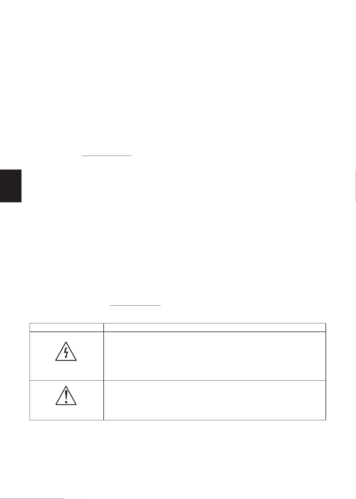
Bass
Audio Language
31
31
0
RAW
Default
On
Preset
Treble
Balance
Digital Audio Output
Off
Surround Sound
TV Speaker
Settings
Setup
Video
Audio
Feature
Enter
To SelectTo Move To Exit
Exit
Time Set
Off
Off
Service 1
Sleep Timer
Advanced Video Menu
Password Set
Parental Control
Digital Captions
Digital Closed Captions
Audio Only
Time Set Menu
Time Set Mode
Time Zone
Time
Manual
Pacific
12:00 AM
To MoveTo Change To Exit
Exit
tuning range is -50 ~ 50.
7. TV Speaker: Choose to turn on / off the
TV internal speaker. The digital audio output
signals and earphone output signals will not
4. Color: Video color chroma adjustment, the
tuning range is 0 ~ 100.
be turn-off even though the TV speaker is
off. The default setting is On.
5. Tint: Video tint adjustment, the tuning range
is R50 ~ G50.
6. BackLight: Backlight strength adjustment,
the tuning range is 0 ~ 10.
7. Settings: Restore the default video settings.
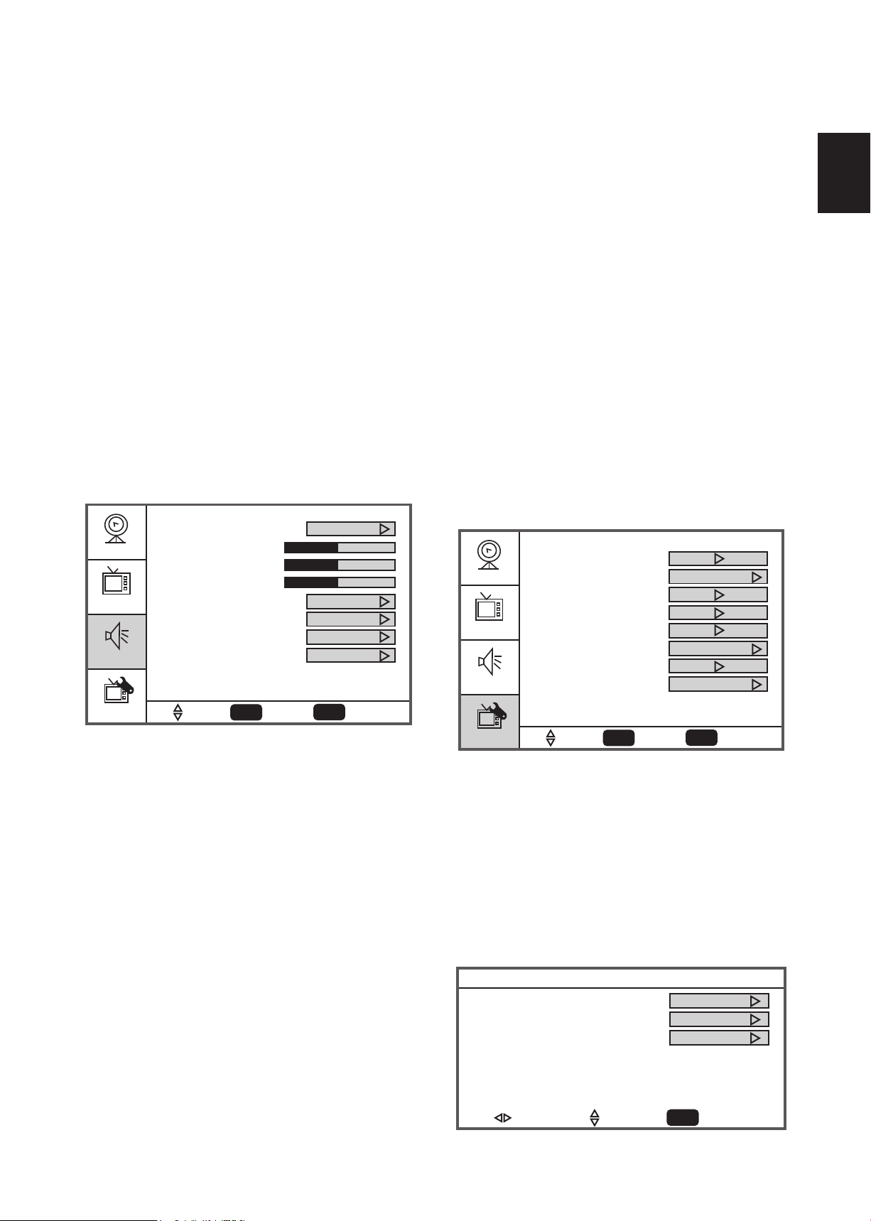
AUDIO MENU
The Audio menu in TV mode shows as below.
It provides audio adjustment for user to modify
the audio setting. Audio language setting is only
available with ATSC TV source, the option is
disable under other source modes.
8. Settings: Restore the default audio settings.
FEATURE MENU
The Feature menu in TV mode shows as below.
It provides certain optional control functions,
such as time set, sleep timer, advanced video
menu, Password Set, parental control (V-chip)
and Digtal closed caption setting. This menu
gives users the most flexibilities to satisfy their
generally demands. According to the various
requirements in different source modes,
certain features should be hidden (disable)
on the menu. The details footnotes will be
described clearly below.
1. Audio Language:Change the audio
language setting on ATSC TV programs The
number of the supported audio languages
depends on the ATSC TV programs.
2. Bass: Bass tone adjustment, the tuning range
is 0 ~ 63. (The default state is enabled)
3. Treble: Treble tone adjustment, the tuning
range is 0 ~ 63. (The default state is enabled)
4. Balance: Audio balance adjustment, the
tuning range is L31 ~ R31.)
5 Surround sound: Switch the stereo sound
effect for audio on/off.
6. Digital Audio Output: Digital audio output
format selection, user can choose RAW
(default) or PCM format or off.
1. Time Set: Set current time. The sub-menu
includesTime Set Mode ,Time Zone and
Time item. [Time Set Mode] user can
choose Auto or Manual, [Time Zone] item
provides user to set current time zone, such
as: Pacific, Alaska, Hawaii, Eastern, Central
and Mountain. [Time] provides user to set
the time clock.
Page 22
English21English
2. Sleep Timer: Enable or disable the TV
Enter Old Password
Enter New Password
Confirm Old Password
Enter Password
Parental Control Menu
USA Parental Locks
Canadian Parental Locks
Enter
To SelectTo Move To Exit
Exit
MPAA TV RATING
USA Parental Locks
Enter
To SelectTo Move To Exit
Exit
NONE
G
PG
PG-13
R
NC-17
X
NONE
ALL FV L S V D
TV-Y
TV-Y7
TV-G
TV-PG
TV-14
TV-MA
standby timer. User can set the TV standby
timer as off / 5 min / 10 min / 15 min/ 30
min / 45 min / 60 min/ 90 min / 120 min /
180min/ 240min. Timer starts to count down
after cursor leaving the sub-menu. (At the
moment, the item shows 『** min Left』and
the cursor highlights on the Feature icon.)
3. Advanced Video Menu: Provide the Noise
Reduction,Color Temperature, 3D Y/C, and
Dynamic Contrast options for enhancing
video quality.
[Noise Reduction] gives four NR effect
degrees, such as: Low,Mid,High and Off. The
default setting is Mid.
[Colour Temp] gives three color
temperature modes as: Normal,Warm and
Cool.
[3D Y/C] provides On / Off switches. The
default setting is On.
[Dynamic Contrast] user can choose 0n
or Off.
[Setting] restores the default advanced
video option settings.
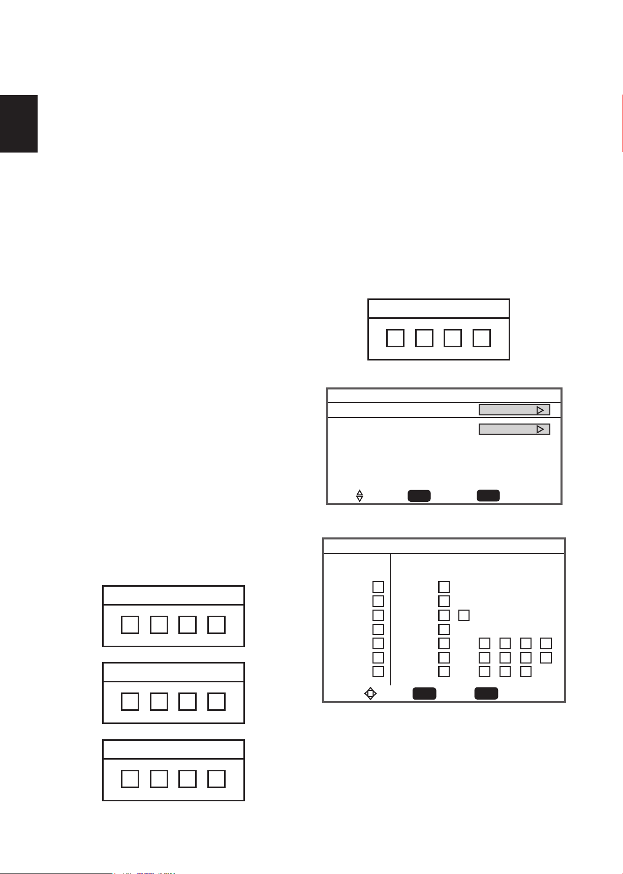
4. Password Set: Change the 4-numeral
parental control password. Three steps are
required for changing the password: Enter
Old Password -> Enter New Password ->
Confirm New Password. Note: This item is
only available in TV, Composite and S-Video
source modes. The default password is 『0 0
0 0』.
5. Parental Control: provide the parental
Control (V-chip) function setting. Before
entering the Parental Control sub-menu,
user has to key in the password first. Enter
the Parental Lock item, then the user can
modify the restricted table about MPAA or
TV Rating respectively. While exiting the
sub-menu, the parental control function is
working. The inhibitive channels or source
signals can be un-lock through pressing the
V-CHIP key on the remote control and then
key in the correct password. Note: This
feature is only available in TV, Composite
and S-Video source modes. (The default
password is: 0 0 0 0.)
6. Digital Captions: Select the closed caption
option ( Service 1-6, Text 1-4 and CC 1-4)
in digital TV mode. When select service 1 to
service 6 you can modulate parameters in
the Digital Close Caption.
Page 23
22
English
English
7. Digital Closed Caption: Provide numerous
Enter
To SelectTo Move To Exit
Exit
Style
Digital Closed Caption
Small
Custom
Default
White
Solid
Red
Solid
Depressed
Red
Size
Font
Text Color
Text Opacity
Background Color
Background Opacity
Edge Effect
Edge Color
CLOSED CAPTION SAMPLE
Component setting-720x480i@30/29.97Hz
H-Position
V-Position
Clocke
Phase
50
50
50
50
Auto Adjust
Setting Preset
Enter
To SelectTo Move To Exit
Exit
VGA setting - 1360x768x60
H-Position
V-Position
Clocke
Phase
50
50
50
50
Auto adjust
Setting Preset
Enter
To SelectTo Move To Exit
Exit
options for setting the digital closed caption
style in the sub-menu.
[Style]item can be set as Automatic or
Custom mode. If Custom mode is selected,
user can modify the detail styles described
below. The setting result will be shown
immediately on the bottom of the sub-menu
[Edge Color]: The colors of text edge
effects, which provides Red
/ Green / Blue / Yellow /
Magenta / Cyan / Black /
White Colors
8. Audio only: This function is for those
programs with audio only and without the
display. When the audio only is on, you could
still modify the volume.
OSD. Note: This feature is only available in
Digital TV(ATSC) mode.
9. Component Set: This option only shows
and is available in component mode, which
provides fine tuning component display,
such as: [H-Position]‚ [V-Position],
[Clock],[Phase] and [Auto Adjust]. All
these items are giving the tuning range from
0 to 100. [Setting] provides the default
component setting values restoring.
[
Size]: Digital closed caption font size, which
can be set as Small,Normal or Large.
[
Font]: Digital closed caption font style,
which can be chosen as Default or
Font 1 ~ 7.
[
Text Color]: Giving Red / Green / Blue/
Yellow / Magenta / Cyan /
Black / White Colors.
[
Text Opacity]: Giving Transparent /
Translucent / Solid /
Flashing modes.
[
Background Color]: Giving Red / Green
/ Blue / Yellow /
Magenta / Cyan /
Black / White Colors.
[
Background Opacity]: Giving Transparent
[
Edge Effect]: The text edge effects,
which gives None / Raised
/ Depressed / Uniform /
Left Shadow / Right Shadow
modes.
10. VGA Set: This option only shows and is
available in VGA mode, which provides
several items for the VGA display
fine tuning, such as : [H-Position],
[V-Position], [Clock] and [Phase]. All
these items giving the tuning range from 0
to 100. [Setting]provides the default VGA
setting values restoring.
/ Translucent /
Solid / Flashing
modes.
Page 24

English23English
TIPS
Care of the screen
Do not rub or strike the screen with anything
hard as this may scratch, mar, or damage the
screen permanently.
Unplug the power cord before cleaning the
screen. Dust the TV by wiping the screen
and the cabinet with a soft, clean cloth. If the
screen requires additional cleaning, use a
clean, damp cloth. Do not use liquid cleaners
or aerosol cleaners.
Mobile telephone warning
To avoid disturbances in picture and sound,
malfunctioning of your TV or even damage
to the TV, keep away your mobile telephone
from the TV.
End of life directives
We are paying a lot of attention to produce
environmental friendly in green focal areas.
Your new receiver contains materials, which
can be recycled and reused.
At the end of its life, specialized companies
can dismantle the discarded receiver to
concentrate the reusable materials and to
minimize the amount of materials to be
disposed of.
Please ensure you dispose of your old
receiver according to local regulations.
instructions, may cause harmful interference
to radio communications. However, there is
no guarantee that interference will not occur
in a particular installation. If this equipment
does cause harmful interference to radio or
television reception, which can be determined
by turning the equipment off and on, the user is
encouraged to try to correct the interference
by one or more of the following measures:
Reorient or relocate the receiving
antenna.
Increase the separation between the
equipment and the TV.
Connect the equipment into wall power
outlet on a circuit different from that to
which the receiver is connected.
Consult the dealer or an experienced
radio or television technician for help.
Modifications –
The FCC requires the user to be notified that
any changes or modifications made to this
device that are not expressly approved by
our company may void the user’s authority to
operate the equipment.
Cables –
Connections to this device must be made with
shielded cables with metallic RF/EMI connector
hoods to maintain compliance with FCC Rules
and Regulations.
Canadian notice –
Regulatory Notices – Federal
Communications Commission Notice
This equipment has been tested and found
to comply with the limits for a Class B digital
device, pursuant to part 15 of the FCC
Rules. These limits are designed to provide
reasonable protection against harmful
interference in a residential installation.
This equipment generates, uses, and can
radiate radio frequency energy and, if not
installed and used in accordance with the
This Class B digital apparatus meets all
requirements of the Canadian InterferenceCausing Equipment Regulations.
Avis Canadian –
Cat apparel numerous de la classed B
respected toutes les exigencies du règlement
sur le materiel brouilleur du Canada.
Page 25

24
English
English
PRODUCT SPECIFICATION
NOTE
* This model complies with the specifications
listed below.
* Designs and specifications are subject to
AUDIO: 500mv(rms)
Supported resolutions: 1080P, 1080i, 720p, 480p,
480i
change without notice.
* This model may not be compatible with
features and/or specifications that may be
added in the future.
* 47” LCD TV Viewable image size: 1193mm
HDMI Terminals:
HDMI INPUT: Rear HDMI x2, Side HDMI x1
HDCP compliant
E-EDID compliant
Supported scan rates: 1080p, 1080i, 720p, 480p,
Television System:
480i
NTSC standard
ATSC standard (8-VSB, Clear-QAM)
VGA Terminals:
VGA INPUT:
Channel Coverage:
VHF: 2 through 13
UHF: 14 through 69
Cable TV: Mild band (A - 8 through A - 1, A
through I )Super band (J through W)Hyper
band (AA through ZZ, AAA, BBB)Ultra band (65
through 94, 100 through 125)
Rear VGA (D-SUB 15 Pin) Input x1
E-EDID compliant
Supported scan rates:
640X480/60Hz/72Hz/75Hz
720X400 /70Hz
800x600 /56Hz /60Hz /72Hz/75Hz
1024X768 /60Hz/70Hz/75Hz
1920X1080 /60Hz
Power Source:
AC power supply: 100V~240 V, 50/60 Hz
Power Consumption
300 W
≤
1 W in standby mode (power cord plugged in
and power OFF)
Recommended: 1920X1080 /60Hz
Audio INPUT: Headphone Mini-jack for stereo
(3.5Ø )
Dimensions:
Include Stand:
1125mm(W) x 767mm(H) x 290mm(L)
Audio Power
10 W + 10 W, Internal Speaker
Video/Audio Terminals:
Rear AV x1: S-Video/Video/Audio Input
Side AV x1: S-Video/Video/Audio Input
S-VIDEO INPUT:
Y : 1 V(p-p), 75 ohm, negative sync.
C : 0.286 V(p-p) (burst signal), 75 ohm
VIDEO/AUDIO INPUT:
VIDEO: 1 V(p-p), 75 ohm, negative sync.
AUDIO: 500mV(rms)
Component INPUT:
Rear Component x2:
Y : 1V(p-p), 75 ohm, including sync.
Pr/Cr: ±0.35V(p-p), 75 ohm
Pb/Cb: ±0.35V(p-p), 75 ohm
Weight:
27kg(With Stand)
Wall Mounting:
400x200mm
(Wall mount kit is not included)
Supplied Accessories:
1pcs Power cord
1pcs Remote control
(with two size AAA alkaline batteries)
1pcs User manual
1pcs Setup Guide
Page 26
English25English
BEFORE CALLING SERVICE
Please make these simple checks before calling service. These tips may save you time and money
since charges for receiver installation and adjustments of customer controls are not covered
under your warranty.
Symptoms Items to Check and Actions to follow
“Ghost ” or double image * This may be caused by obstruction to the antenna
due to high rise buildings or hills. Using a highly
directional antenna may inprove the picture.
No power * Check if the TV’s AC power cord is plugged into
the mains socket.
* Unplug the TV, wait for 60 seconds. Then
re-insert plug into the mains socket and turn on
the TV again.
No picture * Check antenna connections at the rear of the TV
to see if it is properly connected to the TV.
* Possible broadcast station trouble.
Try another channel.
*Adjust the contrast and brightness settings.
* Check the Closed Captions control. Some TEXT
modes could block the screen,
Good picture but no sound *Increase the VOLUME.
* Check if the TV is muted, press the MUTE button
on the remote control.
Good sound but poor color * Adjust the contrast, color and brightness settings.
Poor picture * Poor picture quality may occur when an activated
S-VHS camera or camcorder is connected to
your TV and the other peripheral at the same
time. Switch off one of the peripherals.
Snowy picture and noise *Check the antenna connection
Horizontal dotted line * This may be caused by electrical interference (e.g.
hairdryer, nearby neon lights, etc.)
*Turn off the equipment.
Television not responding to remote control * Check whether the batteries are working.
Replace if necessary
* Clean the remote control sensor lens on the TV.
* You can still use the buttons at the front of your
TV.
* Select the TV mode to ensure your remote
control is set in the TV mode.
Page 27

26
English
English
GLOSSARY
HDTV
HDTV displays are technically defined as being capable of displaying a minimum of 720p
or 1080i active scan lines.
HDMI Inputs
High-Definition Multimedia Interface
Audio / Video Inputs
Located on the rear of the receiver, these connectors (RCA phono type plug) are
used for the input of audio and video signals. Designed for use with VCRs (or other
accessories) in order to receive higher picture resolution and offer sound connection
options.
Menu
An on-screen listing of features shown on the TV screen is made available for user
adjustments.
MPAA
Motion Picture Association of America
Multichannel Television sound (MTS)
The broadcasting standard, which allows stereo sounds to be transmitted with the TV
picture.
RF
Radio Frequency or modulated signal design used as the carrier for television broadcasts.
Second Audio Program (SAP)
Another or additional audio channel provided for in the Multichannel Television Sound
(MTS) broadcast standard. A monaural soundtrack included within the recorded or
video signal (usually containing a second language translation for the displayed program).
Sleep Timer
You can set a time period for which the TV will be turn off automatically.
S-Video Input
You can connect your TV set to a high-resolution video source (such as Super VHS
video-cassette recorder, Laser Disc player and DVD Home Theater Set)
in-order to provide maximum consumer viewing satisfaction.
Page 28

English27English
Page 29

TABLE DES MATIÈRES
AVIS DE TRANSITION A LA TELEVISION NUMERIQUE ....................1
POUR VOTRE SÉCURITÉ ..............................................................................2
PRÉCAUTIONS ET RAPPELS ....................................................................... 3
CONSIGNES DE SÉCURITE IMPORTANTES ..........................................4
CONTENU DU CARTON ........................................................................... 5
PREPARATION .................................................................................................6
FIXER LA BASE .........................................................................................................................6
PRÉPARATION DE VOTRE LCD HDTV POUR LE MONTAGE MURAL ..................6
GUIDE DE CONNEXION DES PERIPHERIQUES ..................................8
INSTRUCTIONS D’UTILISATION..............................................................9
POUR UTILISER LES COMMANDES DU PANNEAU AVANT .....................................9
POUR UTILISER LA TÉLÉCOMMANDE ......................................................................... 10
ILLUSTRATIONS DES ILLUSTRATIONS DES MODES DE VISIONNAGE ............. 11
EQUIPEMENT DE CONNEXION .................................................................................... 13
POUR UTILISER LES MENUS ............................................................................................. 19
MENU SETUP (configuration) ............................................................................................ 19
MENU VIDEO ......................................................................................................................... 20
MENU AUDIO ........................................................................................................................ 21
MENU DES FONCTIONS ................................................................................................... 21
CONSEILS ............................................................................................................................... 24
CARACTERISTIQUES DU PRODUIT ......................................................25
French
AVANT D’APPELER POUR UNE RÉPARATION ...................................26
GLOSSAIRE .....................................................................................................27
Page 30
AVIS DE TRANSITION A LA TELEVISION NUMERIQUE
SA 1965
SA 1966
Cet appareil contient un tuner pour la télévision numérique, de sorte qu’il devrait recevoir les
programmes de TV en numérique avec une antenne convenable, après la terminaison de la diffusion
complète de la TV analogue à pleine puissance aux Etats-Unis le 17 février 2009. Certains vieux
récepteurs de télévision, s’ils marchent avec une antenne TV , auront besoin d’un convertisseur de TV
pour recevoir les programmes de TV en numérique, mais devrait continuer à fonctionner comme avant
pour d’autres besoins (par ex., pour regarder des stations TV en analogue à faible puissance qui diffusent
toujours en analogue, regarder des films préenregistrés, ou jouer des jeux vidéo).
Pour plus d’informations,
appelez la FCC à 1-888-CALL-FCC (1-888-225-5322)
ou consultez le site à www.DTV.gov. Pour en savoir plus sur le programme de convertisseur de TV et sur
les coupons du gouvernement qui peuvent être utilisés pour l’achat d’un nouveau téléviseur,
consultez le site à www.dtv2009.gov,
ou appelez la NTIA à 1-888-DTV-2009.
French
AVISO RELATIVO A LA TRANSICIÓN A TELEVISIÓN DIGITAL
Este equipo incorpora un sintonizador de televisión digital, lo que le permitirá recibir una programación
digital televisada por aire, con una antena adecuada, cuando se terminará la transmisión de alta potencia
de la televisión analógica en los Estados Unidos el 17 de febrero de 2009. Ciertos receptores de
televisión antiguos, si dependen de una antena de TV, necesitarán un conversor de TV para recibir por el
aire una programación digital, pero seguirán funcionando como antes para otros usos (por ejemplo para
ver emisoras de TV de baja potencia que todavía transmiten en analógico, para ver películas pregrabadas,
o para utilizar sus videojuegos).
Para obtener más información,
llame FCC 1-888-CALL-FCC (1-888-225-5322)
o refiérase a www.DTV.gov. Para toda información sobre el programa de conversores de
TV, y acerca de los cupones del gobierno que se pueden usar
para comprarlos, refiérase a www.dtv2009.gov,
o llame al NTIA al 1-888-DTV-2009
SYMBOLES DÉFINITION DE SYMBOLES
TENSION DANGEREUSE: Le symbole de l’éclair avec la flèche
dessinée à l’intérieur d’un triangle avertit l’utilisateur de la présence de
“tension dangereuse” non isolée au sein du logement du produit qui
peut avoir une amplitude suffisante pour constituer un risque de choc
électrique aux personnes.
INSTRUCTIONS: Le point d’exclamation dessiné à l’intérieur d’un
triangle avertit l’utilisateur de la présence d’importantes instructions
d’opération et d’entretien (réparation) dans la documentation
accompagnant l’appareil.
Il ne faut pas exposer l’appareil à des gouttes ou des éclaboussures et aucun objet contenant des
liquides, comme des vases, ne sera placé sur l’appareil.
Attention - Danger d’explosion si la batterie n’est pas correctement remplacée. Ne remplacer
qu’avec le même type ou équivalent.
1
Page 31

2
French
French
Hg
POUR VOTRE SÉCURITÉ
Avant de faire fonctionner le téléviseur veuillez lire soigneusement ce manuel. Ce manuel doit être
conservé pour toute référence ultérieure.
Déclaration concernant les interférences de fréquences radio FCC-Classe B
ATTENTION:
(POUR LES MODÈLES CERTIFIÉS FCC)
REMARQUE:
numérique de Classe B, conformément à la Section 15 du règlement de la FCC. Ces limites sont
conçues pour fournir une protection raisonnable contre les interférences néfastes en installation
résidentielle. Ce matériel génère, exploite et peut émettre un rayonnement de fréquence radio ; en cas
d'installation ou d'utilisation non conforme aux instructions fournies dans ce manuel, il peut provoquer
des interférences indésirables avec les réceptions radio. Cependant, il n’y a aucune garantie que des
interférences ne se produiront pas dans une installation particulière. Si cet appareil occasionne des
interférences néfastes sur la réception radio ou télévisée, ce qui peut se déterminer en éteignant
l’appareil et en le rallumant, l’utilisateur est encouragé à essayer de corriger l’interférence par une ou
plusieurs des mesures suivantes:
1. Réorientez ou déplacez l’antenne réceptrice.
2. Augmentez la distance entre l’appareil et le récepteur.
3. Branchez l’appareil dans une prise de courant sur un circuit différent de celui auquel le récepteur
est branché.
Consultez le revendeur ou un technicien radio/TV expérimenté pour de l’aide.
4.
Cet équipement a été testé et est conforme aux limitations pour un périphérique
AVIS
1. Toute modification non expressément approuvée par la partie responsable de la conformité peut
annuler le droit pour l’utilisateur de faire fonctionner cet appareil.
2. Des câbles d’interface et le cordon d’alimentation CA blindés, s’il y a lieu, doivent être utilisés afin
de se conformer avec les limites sur les émissions.
3. Le fabricant n’est pas responsable pour toutes interférences radio ou TV causées par une
modification non autorisée à cet équipement. C’est la responsabilité de l’utilisateur que de corriger
ladite interférence.
ATTENTION:
Pour éviter des risques d’incendies ou d’électrochocs, n’exposez pas le poste à la pluie ou l’humidité.
Des tensions dangereusement hautes sont présentes à l’intérieur du moniteur. N’ouvrez pas le boîtier.
Les réparations doivent uniquement être confiées au personnel qualifié.
SÉCURITÉ: Élimination de la lampe
LA/LES LAMPE(S) À L’INTÉRIEUR DE CE PRODUIT CONTIEN(NEN)T DU MERCURE ET
DOI(VEN)T ÊTRE RECYCLÉE(S) OU ÉLIMINÉE(S) CONFORMÉMENT AUX LOIS MUNICIPALES,
ÉTATIQUES OU FÉDÉRALES. POUR EN SAVOIR PLUS, CONTACTER L’ALLIANCE DES INDUSTRIES
ÉLECTRONIQUES À WWW.EIAE.ORG.
Page 32

French
3
French
PRÉCAUTIONS ET RAPPELS
1
2
3
4
5
6
7
8
9
0
1
2
3
4
5
6
7
8
9
0
1
2
3
4
5
6
7
8
9
0
Placez l’appareil sur des
surfaces planes.
Débranchez immédiatement
s’il y a un mauvais
fonctionnement comme pas
d’images, pas de vidéo/audio,
fumée et mauvaise odeur
du TV.
Débranchez immédiatement
s’il y a d’autres matériaux
qui sont mis à l’intérieur
du boîtier de TV ou si la TV
tombe.
Interdit/Eviter d’ouvrir le
boîtier de la TV.
Ne couvrez pas ou ne
bloquez pas les orifices ou
les évents. Une ventilation
inadéquate peut raccourcir
la durée de vie de votre TV
et causer de la surchauffe.
Evitez les radiations solaires
directes, la poussière, et les
zones à humidité élevée et
enfumées.
Ne jetez aucun objet à
l’intérieur du boîtier de
TV comme des métaux
ou d’autres matériaux
inflammables.
Ne mettez pas votre TV
dans des espaces confinés
ou dans un boîte quand
vous l’utilisez.
Rappelez-vous de débrancher
le cordon d’alimentation CA
de la prise électrique CA
avant le nettoyage. N’utilisez
pas de nettoyants liquides ou
de nettoyants en aérosols
pour nettoyer l’écran.
Assurez-vous de débrancher
l’appareil quand vous ne
l’utilisez pas pendant une
longue période de temps
(jours).
Appelez le personnel
d’entretien pour nettoyer la
partie interne de la TV une
fois par an.
Ne placez pas l’écran à
proximité d’eau, telle qu’une
baignoire, un lavabo, un
évier de cuisine, un bac
à laver, une piscine ou un
sous-sol humide.
Avis pour la télécommande
Eviter de la faire tomber
Evitez de renverser
des liquides
Evitez des nettoyants
en aérosols
Page 33

4
French
French
CONSIGNES DE SÉCURITE IMPORTANTES
Lisez avant de faire fonctionner cet équipement
1. Lisez ces instructions.
2. Conservez ces instructions.
3. Soyez attentif à tous les avertissements.
4. Suivez toutes les instructions.
5. N’utilisez pas cet appareil à proximité d’une source d’eau.
6. Nettoyez qu’avec un chiffon sec.
7. Ne bloquez pas les orifices d’aération. Installer conformément aux instructions du fabricant.
8. N’installez pas l’appareil à proximité de sources de chaleur comme des radiateurs, des
registres de chaleur, des fours ou d’autres appareils (notamment des amplificateurs) qui
produisent de la chaleur.
9. Ne désactivez pas l’objectif de la prise polarisée ou de type de mise à la terre. Une prise
polarisée comporte deux lames dont l’une plus large que l’autre Une prise de type mise à la
terre comporte deux lames et une troisième broche de mise à la terre. La lame plus large
ou la troisième broche est fournie pour votre sécurité. Si la prise fournie ne rentre pas dans
votre prise, consulter un électricien pour le remplacement de la prise obsolète.
10. Protégez le cordon d’alimentation de sorte qu’on ne risque pas de marcher dessus ni de le
pincer, spécialement au niveau des prises, des prises d’alimentation et au point de sortie de
l’appareil.
11. N’utilisez que les équipements/accessoires spécifiés par le fabricant.
12. N’utilisez cet appareil qu’avec le chariot, le pied, le trépied, le support ou la table
recommandé par le fabricant ou vendu avec l’appareil. Quand un chariot est utilisé, soyez
prudent en déplaçant l’ensemble chariot/appareil pour éviter toute blessure pouvant résulter
de culbutes.
13. Le moniteur doit fonctionner depuis le type de source de courant indiqué sur l’étiquette. Si
vous n’êtes pas sûr(e) du type d’alimentation électrique chez vous, consultez votre revendeur
ou votre fournisseur local.
14. Débranchez cet appareil lors d’orages ou quand vous ne l’utilisez pas durant des périodes
prolongées.
15. Référez tout l’entretien à du personnel d’entretien qualifié. Une réparation est nécessaire
lorsque l’appareil a été endommagé de quelque façon que ce soit, comme des dommages au
cordon d’alimentation, du liquide renversé ou des objets tombés à l’intérieur de l’appareil,
l’appareil a été exposé à la pluie ou l’humidité, il ne fonctionne pas normalement ou il est
tombé.
16. Ce produit peut contenir du plomb ou du mercure. La mise au rebut de ces matériaux peut
être soumise à des réglementations pour des considérations environnementales. Pour toute
information sur la mise au rebut ou le recyclage veuillez contacter vos autorités locales ou
l’alliance des industries de l’électronique: www.eiae.org
17. Dommages nécessitant une réparation — L’appareil doit être réparé par du personnel de
réparation qualifié quand:
A. Le cordon de l’alimentation ou la prise a été endommagé; ou
B. Des objets sont tombés ou un liquide a été renversé dans l’appareil, ou.
C. L’appareil a été exposé à la pluie, ou
D. L’appareil ne semble pas fonctionner normalement ou présente un changement marqué
dans son fonctionnement, ou
E. L’appareil est tombé ou le boîtier est abîmé.
Page 34

French
5
French
ANTENNA
ANTENNA DISCHARGE UNIT
GROUNDING CONDUCTORS
POWER SERVICE GROUNDING ELECTRODE SYSTEM
GROUND CLAMPS
ELECTRIC SERVICE E QUIPMENT
GROUND CLAMP
18. Pivotement/Stabilité – Toutes les télévisions doivent se conformer aux normes de sécurité
internationales recommandées pour les propriétés d’inclinaison et de stabilité du design de
leurs boîtiers.
Ne transigez pas avec ces normes de design en appliquant une force de traction excessive
●
au devant, ou au sommet, du boîtier, ce qui pourrait bel et bien retourner le produit.
Aussi, ne vous mettez pas en danger, ou les enfants, en plaçant de l’équipement
●
électronique /jouets sur le dessus du boîtier. Lesdits éléments pourraient de manière
imprévue tomber du haut du poste de télévision et causer des dommages au produit et/
ou des blessures personnelles.
19. Montage mural ou au plafond – L’appareil ne doit jamais être monté sur un mur ou un
plafond sans suivre les conseils du fabricant.
20. Lignes électriques – Une antenne extérieure devrait être située loin des lignes électriques.
21. Mise à la terre de l’antenne d’extérieur – Si un système d’antenne d’extérieur est
branché au récepteur, assurez-vous que le système d’antenne est mis à la terre en guise de
protection contre des sautes de tension et des charges statiques d’accumulation.
La section 810 du code national électrique (NEC) fournit des informations relatives à une
bonne mise à la terre de la masse et une bonne structure de soutien, la mise à la terre du fil
d’entrée à une unité de décharge d’antenne, la section des conducteurs de mise à la terre,
la disposition d’une unité de décharge d’antenne, la connexion aux câbles de terre et les
conditions concernant le câble de terre. Consultez la Figure ci-dessous.
22. Pénétration d’objets et de liquides – Prenez garde que des objets ne tombent pas ou
CONTENU DU CARTON
EXEMPLE DE MISE A LA TERRE D’ANTENNE SELON LE CODE ELECTRIQUE NATIONAL
remarque à l’installateur du système CATV: Ce rappel est donné pour attirer l’attention les
installateurs du système de câblodistribution sur l’Article 820-40 du code national électrique
(NEC) qui fournit des instructions sur une bonne mise à la terre et spécifie en particulier
que le câble de terre sera correctement branché au système de mise à la terre du bâtiment
ou aussi près que possible de l’entrée du câble.
Veuillez brancher la fiche d’alimentation à la prise murale après avoir raccordé la TV au
cordon d’alimentation!
que des liquides ne giclent pas à l’intérieur du boîtier par les ouvertures.
Unité TV AOC L47H861
●
Télécommande
●
Deux piles (AAA) pour la télécommande
●
Base
●
Quatre vis (pour attacher la Base au pied)
●
Cordon d’alimentation
●
Manuel de l'utilisateur
●
Guide de configuration rapide
●
Page 35

6
French
French
PREPARATION
IMPORTANT: N’ appliquez pas de pression sur la zone de l’écran qui peut compromettre
l’intégrité de l’écran. La garantie du fabricant ne couvre pas les abus de l’utilisateur ou les
installations mal faites.
FIXER LA BASE
IMPORTANT: La Base du HDTV doit être assemblée avant toute utilisation..
1. Placer l’appareil de TV la face vers le bas sur une
surface plane et douce (couverture, mousse,
chiffon, etc.) afin de prévenir tout dommage au
HDTV.
2. Alignez soigneusement et insérez la Base au pied.
3. Gentiment poussez la Base vers le HDTV jusqu’à
ce que le mécanisme de verrouillage se verrouille
en place.
4. Insérez les vis fournies au bas de la base.
5. Utilisez un tournevis pour serrer la Base au pied.
PRÉPARATION DE VOTRE LCD HDTV POUR LE MONTAGE MURAL
Nous suggérons que vous gardiez votre TV à au moins 2,36 inches (60 mm) du mur pour
prévenir toute interférence des câbles.
Avant de monter votre TV sur le mur, vous avez besoin de retirer la base.
Pour fixer un collier de montage mural à votre TV:
1 Retirez les deux pièces T4 et les quatre vis M4 retenant votre téléviseur au support.
2 Fixez le support de montage mural au dos du téléviseur à l'aide de six vis M6, tel
qu'indiqué sur l'illustration.
Remarque
Le collier de montage mural 400 mm x 200 mm et les vis M6 ne sont pas fournis.
Page 36

French
7
French
POWER
VIDEO COMP PC/HDMI TV
Power Key
Min
1 m
Veuillez brancher la fiche d’alimentation à la
prise murale après avoir raccordé la TV au
cordon d’alimentation!
1. Installez le pied; placez le téléviseur
sur une surface solide.
Assurez-vous que la TV est placée dans
une position qui laisse passer un flux
d’air libre. Ne couvrez pas les ouvertures
d’aération au dos de l’appareil.
Afin de prévenir toutes situations non
sûres, aucune source de flammes nues,
telles que des bougies allumées, devraient
être placées dessus ou à proximité.
Eviter la chaleur, les radiations solaires
directes et l’exposition à la pluie ou à l’eau.
L’appareil ne sera pas exposé à des gouttes
ou à des éclaboussures.
2. Raccordez le câble de l’antenne ou le câble
CATV à la prise d’antenne ANT IN 75Ω
à l’arrière du poste de TV.
3. Télécommande:
Retirez le couvercle du compartiment de
la pile. Insérez les 2 piles fournies (Type
AAA 1,5 V).
4. Alimentation:
Insérez le cordon d’alimentation dans la
prise murale ayant une source électrique
CA. Vous pouvez voir les états des voyants
DEL sur le panneau frontal. Si la couleur
du voyant DEL est Verte, cela signifie que
le poste de TV est allumé. Si la couleur du
voyant DEL est Orange, ce qui signifie que
le poste de TV est dans l’état de veille.
5. Mettez la TV sous tension:
Poussez la touche POWER
(ALIMENTATION) sur la télécommande
ou les boutons du panneau de commande
avant. La TV sera mise sous tension en une
minute avec l’affichage sur l’écran.
Touche Power (alimentation)
Page 37
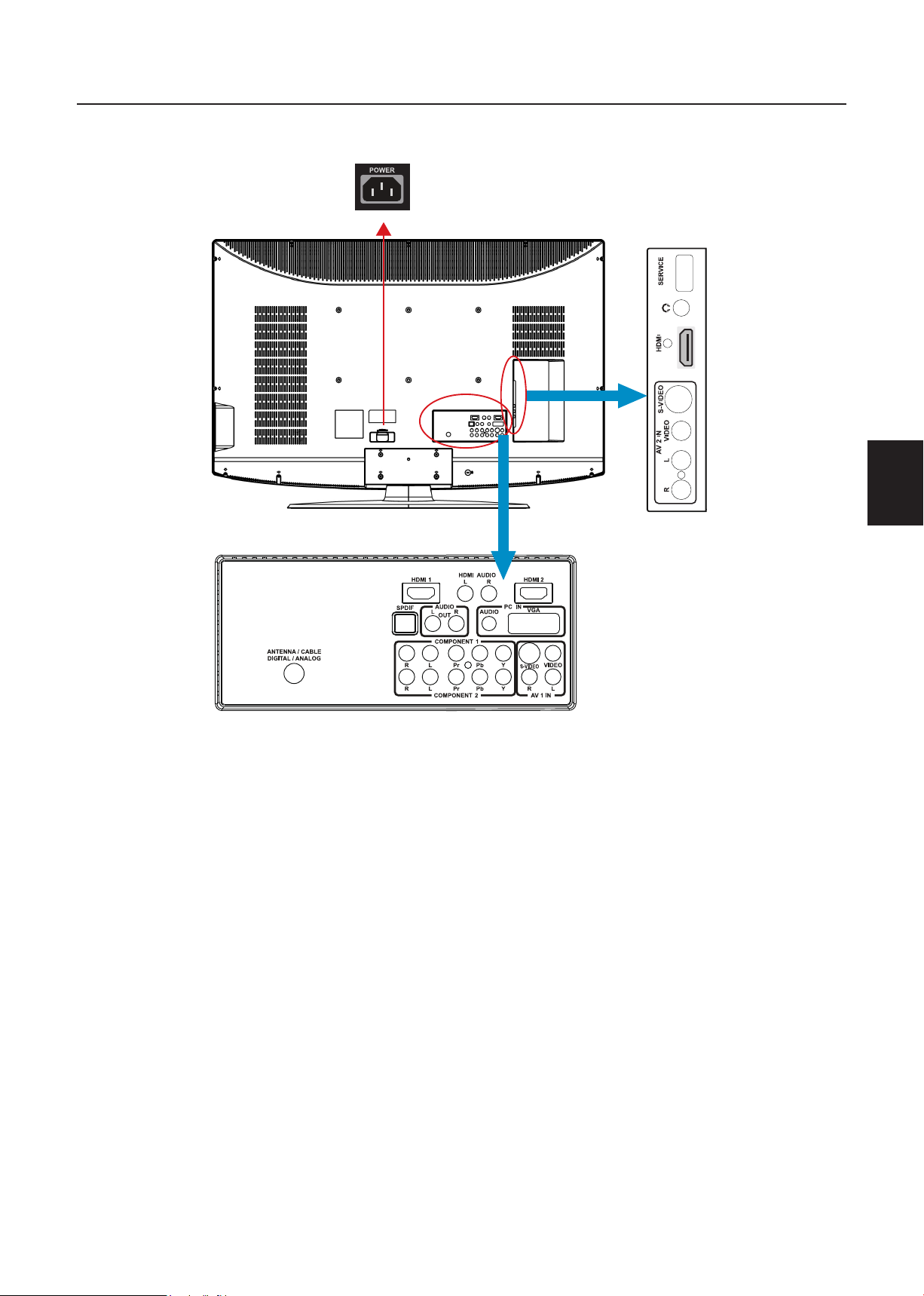
8
French
French
3
AC POWER
GUIDE DE CONNEXION DES PERIPHERIQUES
1. HDMI – Connecte la source principale pour la vidéo numérique tel qu’un lecteur
multimédia de DVD ou un décodeur à travers ce connecteur numérique. La bande de
couleur blanche sur l’arrière de la TV indique cette connexion.
2. PC IN (ENTRÉE PC) – Raccordez ici les câbles vidéo et audio d’un ordinateur.
3. ENTRÉE AV/S-VIDEO IN – Raccordez la source principale pour les dispositifs vidéo
composite tel qu’un magnétoscope ou un jeu vidéo. Utilisez les connecteurs rouge et blanc
pour raccorder l’audio externe depuis la même source. Le signal transmis par le câble et le
connecteur S-Video, si raccordé, prendra la priorité sur le connecteur Vidéo RCA (connecteur
jaune).
4. COMPOSANT (YPb/CbPr/Cr avec Audio L/R) – Raccordez la source principale pour
les dispositifs vidéo composant tels qu’un lecteur de DVD ou un décodeur ici. De gauche
à droite, utilisez pour les entrées le rouge pour Pr, le bleu pour Pb, le vert pour Y, le rouge
pour l’audio droit (D) et le blanc audio gauche (G).
5. DTV – Raccordez à une antenne ou un câble numérique (hors du mur, pas de la boîte de
jonction) pour la TV numérique.*
6. SPDIF (Optical Digital Audio Out - sortie audio numérique optique) - Quand un
signal audio numérique est associé avec l’entrée choisie pour le visionnage, l’audio numérique
sera disponible sur cette connexion SPDIF vers votre cinéma maison.
Une fois que votre équipement est connecté, utilisez la procédure suivante pour visionner le signal d’entrée:
Pressez sur le bouton source sur la télécommande pour sélectionner la source pertinente à visualiser. (ex:
Pressez sur le bouton VIDEO pour sélectionner “Arrière Composite” si vous avez un enregistreur vidéo à
la prise arrière Composite.)
Page 38

French
9
French
1
2
3
5
6
4
7
INSTRUCTIONS D’UTILISATION
POUR UTILISER LES COMMANDES DU PANNEAU AVANT
1 VOL + VOL +: Pressez pour augmenter le niveau du volume du son.
2. VOL - VOL - : Pressez pour diminuer le niveau du volume du son.
▲
3. CH
4. CH
5. MENU Touche Menu: Pressez pour ouvrir ou quitter le menu de l’OSD.
6. INPUT Touche Source: Pressez pour sélectionner la source d’entrée.
7.
▲
▼
ALIMENTATION
CH : Pressez pour sélectionner le numéro de Programme suivant le
plus élevé.
CH : Pressez pour sélectionner le numéro de Programme suivant le
▼
plus bas.
Touche Alimentation Pressez pour allumer / éteindre (veille) la la
télévision. (Veuillez retourner à la TV après que l’état du voyant DEL
Power-ON (alimentation- MARCHE) ait changé à la couleur rouge et
s’est arrêté de clignoter.)
Page 39

10
French
French
POUR UTILISER LA TÉLÉCOMMANDE
POWER
VIDEO
1 2 3
4 5 6
7 8 9
0
PRE CH
COMP PC/HDMI TV
SLEEP
FAV SOURCE
MUTE
MENU EXIT
ENTER
V-CHIP
VIDEO ADJ AUDIO ADJ
CC
DISPLAY
VOLCH
EPG
FREEZE MTS SAP
WIDE
RL57A
POWER (ALIMENTATION)
Pressez pour mettre la TV sous/
hors tension (Veille). (Remarque:
1. La TV n’est jamais totalement
hors tension à moins de la
débrancher physiquement.
2. Pressez pour mettre la TV
sous tension une fois que la
DEL de statut est devenue
rouge et s’est arrêtée de
clignoter.)
VIDEO (VIDÉO)
Pressez à plusieurs reprises
pour choisir le mode de source
S-Vidéo/ Composite.
COMP
Pressez à plusieurs reprises
pour choisir le mode source
Composite.
PC/HDMI
Pressez à plusieurs reprises
pour choisir le mode source
VGA ou HDMI.
TV
Pressez pour choisir le mode
source TV ATSC/NTSC.
0 ~ 9 /- numéro
Pressez pour entrer le numéro
de chaîne TV et sélectionner
une chaîne (Pressez sur ‘-’ ‘pour
indiquer le choix de souschaîne).
SLEEP (SOMMEIL)
Pressez pour régler une durée
(arrêt/5 min /10 min /15 min /30
min/45 min /60min/90min/120
min /180 min /240 min)après
laquelle la TV devrait permuter
d’elle-même au mode Veille.
FREEZE (FIGER)
Pressez pour figer l’image
affichée.
CH-/ CH +
Pressez sur + ou – pour faire
défiler les chaînes ou sources TV.
MENU
Pressez pour ouvrir ou quitter
le menu.
“<”,“>”,“<”,“>”,“ENTREE”
Pressez pour régler les
différents éléments des
fonctions du menu.
MTS/SAP
Pressez pour activer les sons
NTSC TV tels que: Stéréo, SAP
ou Mono. Et langages de DTV.
WIDE (LARGE)
Pressez pour choisir l’aspect
d’affichage tels que: Normal,
Large, Zoom ou mode Cinéma.
SOURCE
Pressez à plusieurs reprises
pour choisir les différentes
sources d’entrée.
EPG (guide de programme
électronique)
Cette fonction n'est pas
disponible.
MUTE (MUET)
Eteindre/allumer le son
DISPLAY (AFFICHAGE)
Pressez pour afficher les
informations concernant la
source d’entrée, la chaîne TV, la
résolution d’affichage et l’heure
actuelle.
VOL- / VOL+
Pressez sur Gauche/Droite
pour régler le volume.
Exit (Quitter)
Pressez pour quitter le menu
ou l’OSD.
V-CHIP (Puce antiviolence)
Pressez pour verrouiller /
déverrouiller Contrôle parental
temporairement. (après avoir
réglé le tableau de restriction
MPAA ou la classification TV.)
VIDEO ADJ
Pressez pour choisir le réglage de
la luminosité ou du contraste.
AUDIO ADJ
Appuyez pour choisir les basses
et les aigus.
CC
Pressez à plusieurs reprises
pour changer les types de soustitres comme CC ON/CC OFF/
CC ON LORS DU SILENCE.
FAVORITE (FAVORI)
Pressez pour permuter le mode
Favori/Normal.
PREV CH
Pressez pour afficher la chaîne
TV précédente
Page 40

French
11
French
ILLUSTRATIONS DES ILLUSTRATIONS DES MODES DE VISIONNAGE
Mode normal sur écran d’afchage en 16:9
Le contenu d’origine serait au centre de
l’écran.
Mode large sur l’écran d’afchage en 16:9
Le contenu d’origine dans ce mode doit
remplir toute la largeur de l’affichage
horizontalement.
Mode large sur l’écran d’afchage en 16:10
Large1 et Large2 s’appliquent:
Large1: Le contenu d’origine remplirait la
totalité de l’écran, tandis que le
rapport approprié du contenu en
16:9 est toujours maintenu. Il est
nécessaire d’avoir un peu de rognure
du contenu sur les côtés.
Large2: Le contenu d’origine remplirait la
largeur de l’écran, tandis que le
rapport approprié du contenu en
16:9 est toujours maintenu. De
petites barres noires sont ajoutées.
Page 41

12
French
French
Mode ZOOM sur l’écran d’afchage en 16:9
Pour les images de format large qui sont à l’origine programmées en cadres de 4:3 avec des
barres noires au sommet et à la base, ce mode doit étirer l’image à la fois dans la largeur et la
hauteur pour un affichage complet avec des informations actives.
Image en 16:9 dans un cadre en 4:3
Même image en mode ZOOM
Mode ZOOM sur l’écran d’afchage en 16:10
Pour les images de format large qui sont à l’origine programmées en cadres de 4:3 avec des
barres noires au sommet et à la base, ce mode doit étirer l’image à la fois dans la largeur et la
hauteur pour un affichage complet avec des informations actives. Il est nécessaire d’avoir un peu
de rognage sur les côtés pour un affichage complet.
Image en 16:9 dans un cadre en 4:3
Même image en mode ZOOM
Mode CINEMA sur l’écran d’afchage en 16:9 ou 16:10
Ce mode est appliqué pour visualiser le contenu de format 2.35:1 sur des affichages en 16:9.
Le rognage sur les deux côtés gauche et droite garde un format d’image régulière pour les
utilisateurs.
Remarque
AOC L47H861 possède 4 formats d’image: Normal, Large, Zoom et Cinéma.
Page 42

French
13
French
EQUIPEMENT DE CONNEXION
Coaxial (RF)
Utilisation de votre antenne ou d’un
câble numérique pour une télévision
numérique.
1. Mettez la télévision à haute définition hors
tension.
2. Connectez la prise coaxiale (RF) de
votre antenne ou câble numérique (prise
murale, non pas de la boîte de câbles) au
connecteur ANTENNA/CABLE DIGITAL/
ANALOG.
3. Mettez la télévision à haute définition sous
tension.
4. Sélectionnez DTV à l’aide du bouton
INPUT (SOURCE) de la télécommande,
sur le côté de la télévision à haute
définition ou directement en appuyant sur
le bouton TV de la télécommande.
Utilisation de l’antenne ou d’un câble
pour votre magnétoscope
1. Mettez la télévision à haute définition et le
magnétoscope hors tension.
2. Connectez la prise “ Sortie vers TV ”, “
Sortie RF ” ou “ Sortie antenne ” à l’arrière
de votre magnétoscope au connecteur
ANTENNA/CABLE DIGITAL/ANALOG à
l’arrière de la télévision à haute définition.
3. Mettez la télévision à haute définition et le
magnétoscope sous tension.
4. Sélectionnez TV à l’aide du bouton INPUT
(SOURCE) de la télécommande, sur le
côté de la télévision à haute définition ou
directement en appuyant sur le bouton TV
de la télécommande.
Utilisation de votre Antenne ou Câble
pour la DTV.
1. Mettez la télévision à haute définition hors
tension.
2. Connectez la prise coaxiale (RF) de votre
antenne ou câble (prise murale, non pas
de la boîte de câbles) au connecteur
ANTENNA/CABLE DIGITAL/ANALOG à
l’arrière de la télévision à haute définition.
3. Mettez la télévision à haute définition sous
tension.
4. Sélectionnez TV à l’aide du bouton INPUT
(SOURCE) de la télécommande, sur le
côté de la télévision à haute définition ou
directement en appuyant sur le bouton TV
de la télécommande.
Remarque
Si vous avez une télévision hors
antenne ou câblée, connectez-la
au connecteur “Entrée d’antenne” à
l’arrière de votre magnétoscope.
Page 43

14
French
French
Connexion du décodeur de votre
télévision à haute dénition
HDMI Utilisation
Les décodeurs de téléviseur à haute définition
qui ont une interface numérique HDMI doivent
être connectés à l’entrée HDMI du téléviseur
haute définition à écran LCD pour des
résultats optimaux.
Connexion du décodeur de votre
télévision à haute dénition (meilleure)
Pour des décodeurs de télévision à
haute dénition avec vidéo numérique
interactive (DVI)
1. Mettez la télévision à haute définition et le
décodeur hors tension.
2. A l’aide d’un câble HDMI-DVI, connectez
l’extrémité DVI du décodeur de votre
télévision à haute définition et l’extrémité
HDMI à l’entrée HDMI à l’arrière de la
télévision à haute définition.
3. Mettez la télévision à haute définition et le
décodeur sous tension.
4. Sélectionnez l’interface HDMI à l’aide
du bouton INPUT (SOURCE) de la
télécommande, sur le côté de la télévision
à haute définition ou directement en
appuyant sur le bouton HDMI de la
télécommande.
1. Mettez la télévision à haute définition et le
décodeur hors tension.
2. Connectez un câble HDMI à la sortie
HDMI du décodeur de votre télévision
à haute définition et l’autre extrémité à
l’entrée HDMI à l’arrière de la télévision à
haute définition.
3. Mettez la télévision à haute définition et le
décodeur sous tension.
4. Sélectionnez l’interface HDMI à l’aide
du bouton INPUT (SOURCE) de la
télécommande, sur le côté de la télévision
à haute définition ou directement en
appuyant sur le bouton HDMI de la
télécommande.
Remarque
L’entrée HDMI sur la télévision à haute
définition prend en charge la protection
des contenus numériques à large bande
(HDCP). La protection HDCP encode
la transmission entre la source vidéo et
l’affichage numérique pour plus de sécurité
et de protection.
Remarque
L’entrée HDMI sur la télévision à haute
définition prend en charge la protection
des contenus numériques à large bande
(HDCP). La protection HDCP encode
la transmission entre la source vidéo et
l’affichage numérique pour plus de sécurité
et de protection.
Référez-vous au manuel d’utilisateur du
décodeur de votre télévision à haute
définition pour plus d’informations sur
les conditions de sortie vidéo du produit
ou consultez votre opérateur de câble ou
satellite.
La connexion DVI à HDMI ne fournit
que de la vidéo. Pour du son, il faut une
connexion à un lecteur audio différent.
Référez-vous au manuel d’utilisateur du
décodeur de votre télévision à haute
définition pour plus d’informations sur
les conditions de sortie vidéo du produit
ou consultez votre opérateur de câble ou
satellite.
Page 44

French
15
French
Utilisation de la vidéo composante
Connexion du décodeur de votre
télévision à haute dénition (meilleure):
Connexion de votre décodeur de base
Utilisation de la vidéo composite
1. Mettez la télévision à haute définition et le
décodeur hors tension.
2. Connectez la prise Pr (couleur rouge)
sur le décodeur de votre télévision à
haute définition à la prise Pr (couleur
rouge) correspondante dans le groupe
Composante.
3. Connectez la prise Pb (couleur bleue)
sur le décodeur de votre télévision à
haute définition à la prise Pb (couleur
bleue) correspondante dans le groupe
Composante.
4. Connectez la prise Y (couleur verte)
sur le décodeur de votre télévision à
haute définition à la prise Y (couleur
verte) correspondante dans le groupe
Composante.
5. A l’aide d’un câble audio (prises rouge et
blanche), connectez le câble aux prises
de sortie audio associées à la sortie
Composante du décodeur de votre
télévision à haute définition et connectez
l’autre extrémité aux connecteurs audio
associés avec le Composant.
1. Mettez la télévision à haute définition et le
décodeur hors tension.
2. A l’aide d’un câble AV, connectez la
prise Vidéo (couleur jaune) sur votre
décodeur à la prise Vidéo (couleur jaune)
correspondante dans le groupe AV à
l’arrière de la télévision à haute définition.
3. A l’aide des prises rouge et blanche,
connectez le câble aux prises de sortie
audio associées à la sortie Vidéo de votre
décodeur et connectez l’autre extrémité
aux connecteurs audio associés à l’entrée
AV à l’arrière de la télévision à haute
définition.
4. Mettez la télévision à haute définition et le
décodeur sous tension.
5. Sélectionnez Composite (vidéo 1) à
l’aide du bouton INPUT (SOURCE) de la
télécommande, sur le côté de la télévision
à haute définition ou directement
en appuyant sur le bouton AV de la
télécommande.
6. Mettez la télévision à haute définition et le
décodeur sous tension.
7. Sélectionnez Composante (vidéo 3) à
l’aide du bouton INPUT (SOURCE) de la
télécommande, sur le côté de la télévision
à haute définition ou directement en
appuyant sur le bouton Component
(composante) de la télécommande.
Remarque
Référez-vous au manuel d’utilisateur du
décodeur de votre télévision à haute
définition pour plus d’informations sur
les conditions de sortie vidéo du produit
ou consultez votre opérateur de câble ou
satellite.
Page 45

16
French
French
Utilisation d’un câble coaxial (RF)
1. Mettez la télévision à haute définition et le
décodeur hors tension.
2. A l’aide d’un câble coaxial (RF), connectez
une extrémité sur le connecteur TV
OUT (RF) de votre décodeur et l’autre
extrémité à l’entrée DTV/TV à l’arrière de
la télévision à haute définition.
3. Mettez la télévision à haute définition et le
décodeur sous tension.
4. Sélectionnez TV à l’aide du bouton INPUT
(SOURCE) de la télécommande, sur le
côté de la télévision à haute définition ou
directement en appuyant sur le bouton
TV (sous le bouton WIDE – Large) de la
télécommande.
Connexion de votre lecteur de DVD
(meilleure)
1. Mettez la télévision à haute définition et le
lecteur de DVD hors tension.
2. Connectez un câble HDMI à la sortie
HDMI de votre lecteur de DVD et l’autre
extrémité à l’entrée HDMI à l’arrière de la
télévision à haute définition.
3. Mettez la télévision à haute définition et le
lecteur de DVD sous tension.
4. Sélectionnez l’interface HDMI à l’aide
du bouton INPUT (SOURCE) de la
télécommande, sur le côté de la télévision
à haute définition ou directement en
appuyant sur le bouton HDMI de la
télécommande.
Remarque
Référez-vous au manuel de l’utilisateur de
votre décodeur pour plus d’informations
sur la sélection des sorties vidéo ou RF du
produit.
Connexion de votre lecteur de DVD
HDMI Utilisation
Les lecteurs de DVD qui possèdent une
interface numérique comme l’interface HDMI
(interface multimédia haute définition) doivent
être connectés à l’entrée HDMI du téléviseur
haute définition à écran LCD pour des
résultats optimaux.
Pour les lecteurs de DVD avec vidéo
numérique interactive:
1. Mettez la télévision à haute définition et le
lecteur de DVD hors tension.
2. A l’aide d’un câble HDMI-DVI, connectez
l’extrémité DVI à votre lecteur de DVD
et l’extrémité HDMI à l’entrée HDMI à
l’arrière de la télévision à haute définition.
3. Mettez la télévision à haute définition et le
lecteur de DVD sous tension.
4. Sélectionnez l’interface HDMI à l’aide
du bouton INPUT (SOURCE) de la
télécommande, sur le côté de la télévision
à haute définition ou directement en
appuyant sur le bouton HDMI de la
télécommande.
Remarque
Référez-vous au manuel d’utilisateur
de votre lecteur de DVD pour plus
d’informations sur les conditions de sortie
vidéo du produit.
La connexion DVI à HDMI ne fournit que
de la vidéo. Pour la sortie audio, il faut une
connexion à un lecteur audio différent.
Page 46

French
17
French
Utilisation de la vidéo composante
Utilisation de S-Vidéo (AV)
Connexion de votre lecteur de DVD
(meilleure)
1. Mettez la télévision à haute définition et le
lecteur de DVD hors tension.
2. Connectez la prise Pr (couleur rouge) sur
votre lecteur de DVD à la prise Pr (couleur
rouge) correspondante dans le groupe
Composante à l’arrière de la télévision à
haute définition.
3. Connectez la prise Pb (couleur bleue) sur
votre lecteur de DVD à la prise Pb (couleur
bleue) correspondante dans le groupe
Composante à l’arrière de la télévision à
haute définition.
4. Connectez la prise Y (couleur verte) sur
votre lecteur de DVD à la prise Y (couleur
verte) correspondante dans le groupe
Composante à l’arrière de la télévision à
haute définition.
5. A l’aide d’un câble audio (prises rouge
et blanche), connectez le câble aux
prises de sortie audio associées à la
sortie Composante de votre lecteur de
DVD et connectez l’autre extrémité aux
connecteurs audio associés avec l’entrée
Composante à l’arrière de la télévision à
haute définition.
6. Mettez la télévision à haute définition et le
lecteur de DVD sous tension.
7. Sélectionnez Composante à l’aide
du bouton INPUT (SOURCE) de la
télécommande, sur le côté de la télévision
à haute définition ou directement en
appuyant sur le bouton Component
(composante) de la télécommande.
Connexion de votre lecteur de DVD
(bonne):
1. Mettez la télévision à haute définition et le
lecteur de DVD hors tension.
2. Connectez la prise S-Vidéo à l’arrière
de votre lecteur de DVD à la prise
S-Vidéo dans le groupe AV à l’arrière de la
télévision à haute définition.
3. Connectez un câble audio (prises rouge
et blanche) aux prises de sortie audio
associées à la sortie S-Vidéo de votre
lecteur de DVD et connectez l’autre
extrémité aux connecteurs audio associés
avec l’entrée AV à l’arrière de la télévision
à haute définition.
4. Mettez la télévision à haute définition et le
lecteur de DVD sous tension.
5. Sélectionnez S-Vidéo (vidéo 2) à l’aide
du bouton INPUT (SOURCE) de la
télécommande, sur le côté de la télévision
à haute définition ou directement
en appuyant sur le bouton AV de la
télécommande.
Remarque
Référez-vous au manuel de l’utilisateur
de votre lecteur de DVD pour plus
d’informations sur les conditions de sortie
vidéo du produit.
Page 47

18
French
French
Utilisation de la vidéo composite (AV)
Connexion de votre lecteur de DVD
(bonne)
1. Mettez la télévision à haute définition et le
lecteur de DVD hors tension.
2. Connectez la prise Vidéo (couleur jaune)
sur votre lecteur de DVD à la prise Vidéo
(couleur jaune) dans le groupe AV.
3. Connectez les prises audio R (couleur
rouge) et L (couleur blanche) sur votre
lecteur de DVD aux prises audio R
(couleur rouge) et L (couleur blanche)
correspondantes dans le groupe AV.
4. Mettez la télévision à haute définition et le
lecteur de DVD sous tension.
5. Sélectionnez Composite (vidéo 1) à
l’aide du bouton INPUT (SOURCE) de la
télécommande, sur le côté de la télévision
à haute définition ou directement
en appuyant sur le bouton AV de la
télécommande.
Connexion de votre caméscope ou
caméra vidéo
1. Mettez la télévision à haute définition et
le caméscope ou la caméra vidéo hors
tension.
2. Connectez la prise S-Vidéo à l’arrière de
votre caméscope ou caméra vidéo à la
prise S-Vidéo dans le groupe AV à l’arrière
de la télévision à haute définition.
3. Connectez un câble audio (prises rouge
et blanche) aux prises de sortie audio
associées à la sortie S-Vidéo de votre
caméscope ou caméra vidéo et connectez
l’autre extrémité aux connecteurs audio
associés avec l’entrée AV à l’arrière de la
télévision à haute définition.
4. Mettez la télévision à haute définition et
le caméscope ou la caméra vidéo sous
tension.
5. Sélectionnez S-Vidéo (vidéo 2) à l’aide
du bouton INPUT (SOURCE) de la
télécommande, sur le côté de la télévision
à haute définition ou directement
en appuyant sur le bouton AV de la
télécommande.
Remarque
Référez-vous au manuel d’utilisateur de
votre caméscope ou caméra vidéo pour
plus d’informations sur les conditions de
sortie vidéo du produit.
Page 48

French
19
French
Setup
Video
Audio
Feature
Tuning Band
DTV Signal
Auto Ch Search
Add On Ch Search
Manual Channel Set
Channel Labels
Menu Language
Aspect Ratio
Favorite Channel Mode
Enter
Exit
To SelectTo Move To Exit
Cable
English
Normal
Off
Faible
Niveau du signal
Normal Bon
95
Connexion à l’ordinateur
1. Mettez la télévision à haute définition et le
magnétoscope hors tension.
2. Connectez un câble RVB (VGA) D-Sub
à 15 broches à la sortie RVB de votre
ordinateur et l’autre extrémité à l’entrée
PC IN à l’arrière de la télévision à haute
définition.
3. Connectez la sortie audio de votre
ordinateur à l’entrée audio PC IN à l’arrière
de la télévision à haute définition.
4. Mettez la télévision à haute définition et
l’ordinateur sous tension.
5. Sélectionnez RVB à l’aide du bouton
INPUT (SOURCE) de la télécommande,
sur le côté de la télévision à haute
définition ou directement en appuyant sur
le bouton RVB de la télécommande.
Remarque
POUR UTILISER LES MENUS
1. Appuyer sur la touche MENU pour
afficher le menu principal.
2. Utilisez le Curseur Haut/Bas pour
sélectionner un élément du menu.
3. Utilisez le Curseur Gauche/Droite pour
entrer dans un sous-menu.
4. Appuyez sur la touche ENTER (entrer)
pour activer/désactiver la fonction.
5. Pressez sur le bouton MENU ou EXIT
(quitter) pour quitter le menu.
Appuyez sur la touche MENU pour entrer
dans le menu OSD. Ajustez les éléments
comprenant le menu de configuration, le
menu vidéo, le menu Audio et le menu
Fonction. Cependant, il se peut que certains
éléments de fonctions dans les menus ne soit
activés que dans les modes sources particuliers.
MENU SETUP (configuration)
Le menu Setup (configuration) en mode TV
est présenté ci-dessous. Dans d’autres modes
sources, le menu Setup (configuration) ne
présente que les éléments Langue du menu
et Format d’image.
Pour la meilleure qualité d’image lors de
la connexion d’un ordinateur à travers la
prise PC IN, réglez le mode d’étalonnage
de votre ordinateur sur la résolution
native du panneau. Veuillez vous référer au
guide de l’utilisateur de l’ordinateur ou de
la carte graphique pour des informations
supplémentaires sur la façon de régler le
mode d’étalonnage et les conditions de
sortie vidéo du produit.
1. Bande de syntonisation: Choisissez entre
Antenne et Câble (télévision par câble) pour
le signal de source TV.
2. Signal de télévision numérique: Montre
l’intensité du signal de télévision numérique
reçu.
Page 49

20
French
French
Setup
Video
Audio
Feature
Enter
To SelectTo Move To Exit
Exit
Contrast 50
50
0
50
0
10
Preset
Brightness
Sharpness
Color
Tint
Backlight
Settings
3. Recherche Ch auto: Balaye
automatiquement toutes les chaînes
télévisées NTSC / ATSC et mémorise la
table de chaînes. Au cours de la procédure
de balayage des chaînes, l’écran OSD peut
afficher le nombre de chaînes qui ont été
trouvées.
4. Ajouter sur recherche Ch: Ajoute des
chaînes qui viennent d’être trouvées.
5. Définition manuelle des chaînes:
Présente la table de configuration des
chaînes. L’utilisateur peut choisir d’afficher
les chaînes ATSC ou NTSC, puis d’éditer
(ajouter/supprimer) les numéros de chaînes.
6. Etiquettes des chaînes: Montre le menu
d’étiquettes de chaînes télévisées NTSC
/ ATSC pour que l’utilisateur modifie les
étiquettes de chaînes en particulier.
7. Langue du Menu: Sélectionne la langue
d’affichage du menu. (English/ Espagnol /
Français)
8. Format d’image: Sélectionne le format
d’image de l’affichage. (Normal/Zoom/Large/
Cinéma)
9. Mode chaînes favorites: En mode chaînes
favorites, l’utilisateur peut éditer la table de
chaînes favorites dans l’option de définition
des chaînes favorites.
MENU VIDEO
Le menu Vidéo dans la plupart des modes
de sources est présenté ci-dessous. Il
propose plusieurs éléments de réglages
vidéo permettant à l’utilisateur de régler
l’affichage vidéo avec précision. Ce n’est que
dans les modes sources VGA que le menu
Vidéo propose simplement les éléments
Contraste, Luminosité, Rétro-éclairage et
Paramètres (préinitialisés).
1. Contraste: Réglage du contraste vidéo, la
plage de réglage va de 0 à 100.
2. Luminosité: Réglage de la luminosité de la
vidéo, la plage de réglage va de 0 à 100.
3. Netteté: Réglage de la netteté de la vidéo,
la plage de réglage va de -50 à 50.
4. Couleur: Réglage de l’indice de couleur de
la vidéo, la plage de réglage va de 0 à 100.
5. Teinte: Réglage de la teinte de la vidéo, la
plage de réglage va de R50 à G50.
6.
Rétro-éclairage: Réglage de la puissance du
rétro-éclairage, la plage de réglage va de 0 à 10.
7. Paramètres: Restaure les paramètres vidéo
par défaut.
Page 50

French
21
French
MENU AUDIO
Setup
Video
Audio
Feature
Enter
To SelectTo Move To Exit
Exit
Bass
Audio Language
31
31
0
RAW
Default
On
Preset
Treble
Balance
Digital Audio Output
Off
Surround Sound
TV Speaker
Settings
Setup
Video
Audio
Feature
Enter
To SelectTo Move To Exit
Exit
Time Set
Off
Off
Service 1
Sleep Timer
Advanced Video Menu
Password Set
Parental Control
Digital Captions
Digital Closed Captions
Audio Only
Time Set Menu
Time Set Mode
Time Zone
Time
Manual
Pacific
12:00 AM
To MoveTo Change To Exit
Exit
MENU DES FONCTIONS
Le menu Audio en mode TV est présenté
ci-dessous. Il propose un réglage audio
permettant à l’utilisateur de modifier les
paramètres audio. La configuration de la langue
audio n’est disponible qu’avec une source TV
ATSC, l’option est désactivée dans les autres
modes de sources.
1. Langue audio: Change la configuration de
la langue audio sur les programmes télévisés
ATSC. Le nombre de langues audio prises
en charge dépend des programmes télévisés
ATSC.
2. Grave: Réglage des basses, la plage de
réglage va de 0 à 63 (l’état par défaut est
activé).
3. Aigu: Réglage des aigus, la plage de réglage
va de 0 à 63 (l’état par défaut est activé).
4. Balance: Réglage de la balance audio, la
plage de réglage va de L31 à R31.
5. Son Surround : Active ou désactive la
stéréo du signal audio.
6. Sortie audio numérique: Choix du
format de sortie numérique. Vous pouvez
choisir entre le format RAW (par défaut)
et le format PCM, ou vous pouvez encore
désactiver (off) la sortie numérique.
7. Haut-parleur TV: Vous pouvez choisir
d'activer ou de désactiver le haut-parleur
interne du téléviseur. La sortie audio
numérique et la sortie casque ne seront pas
désactivées même si le haut-parleur interne
est désactivé. Le réglage par défaut est On
(activé).
8. Paramètres: Pour restaurer les paramètres
audio par défaut.
Le menu Fonctions en mode TV est présenté
ci-dessous. Il propose certaines fonctions de
commandes en option comme la définition de
l’heure, une minuterie de mise en sommeil, un
menu vidéo avancé, la définition d’un mot de
passe, le contrôle parental (puce antiviolence)
et le paramètre de sous-titres numériques.
Ce menu offre une grande flexibilité aux
utilisateurs pour satisfaire leurs exigences en
général. Selon les divers besoins dans différents
modes de sources, certaines fonctions doivent
être cachées (désactivées) sur le menu. Les
notes de bas de page sur les détails seront
clairement décrites ci-dessous.
1. Réglage de l’heure: Règle l’heure
courante.Le sous-menu comprend le Mode
de réglage de l’heure, le fuseau horaire et
les éléments horaires. L’utilisateur du Mode
de réglage de l’heure [Mode de réglage
de l’heure] peut choisir Auto ou Manuel, le
fuseau horaire [Zone horaire] procure à
l’utilisateur la possibilité de régler les fuseaux
horaires, tels que: Pacifique Alaska, Hawaii,
Est Centre et Rocheuses. [Heure] procure
à l’utilisateur la possibilité de régler l’heure
de l’horloge.
Page 51

22
French
French
Entrer l’ancien mot de passe
Entrer le nouveau mot de passe
Confirmer le nouveau mot de passe
Saisir le mot de passe
Parental Control Menu
USA Parental Locks
Canadian Parental Locks
Enter
To SelectTo Move To Exit
Exit
MPAA TV RATING
USA Parental Locks
Enter
To SelectTo Move To Exit
Exit
NONE
G
PG
PG-13
R
NC-17
X
NONE
ALL FV L S V D
TV-Y
TV-Y7
TV-G
TV-PG
TV-14
TV-MA
2. Minuterie de mise en sommeil: Active
ou désactive la minuterie de mise en veille
du téléviseur. L’utilisateur peut régler la
minuterie de mise en veille du téléviseur sur
désactivée/ 5 min / 10 min / 15 min/ 30 min /
45 min / 60 min/ 90 min / 120 min / 180 min
/ 240 min. La minuterie démarre le compte
à rebours une fois que le curseur a quitté le
sous-menu. (en ce moment, l’élément indique
『
** min restantes』et le curseur met l’icône
Fonctions en surbrillance.)
3. Menu vidéo avancé: Propose la Réduction
du bruit, la Température des couleurs et 3D
Y/C. Des options de contraste dynamique
pour améliorer la qualité vidéo.
[Réduction du bruit] propose quatre
degrés d’effet de réduction du bruit, comme:
Bas, Moyen, Elevé et Eteint. Le paramètre
par défaut est Moyen.
[Temp couleurs] donne trois mode de
température des couleurs: Normal, Chaud
et Froid.
[3D Y/C] propose les interrupteurs marche/
arrêt. L’option par défaut est Activé.
[Contraste dynamique] l’utilisateur peut
choisir Activé ou Désactivé.
[Paramètre] restaure les paramètres des
options vidéo avancées.
4. Réglage du mot de passe: Change le mot
de passe à 4 chiffres du contrôle parental.
Trois étapes sont nécessaires pour changer
le mot de passe: Entrer l’ancien mot de
passe -> Entrer le nouveau mot de passe
-> Confirmer le nouveau mot de passe.
Remarque: Cet élément n’est disponible que
dans les modes sources TV, Composite et
S-Vidéo. Le mot de passe par défaut est 『0
0 0 0』.
5. Contrôle parental: fournit le réglage de
la fonction Contrôle parental (puce anti-V).
Avant d’entrer dans le sous-menu Contrôle
parental, l’utilisateur doit d’abord saisir le
mot de passe. Ensuite, après avoir entré
l’élément de verrouillage Parental, l’utilisateur
peut modifier le tableau limité sur les
classements TV ou MPAA respectivement.
Quand il quitte le sous-menu, la fonction
Contrôle parental fonctionne. Les chaînes
ou les signaux de sources bloqués peuvent
être déverrouillés en pressant sur la touche
V-CHIP sur la télécommande et en entrant
ensuite le mot de passe correct. Remarque:
Cette fonction n’est disponible que dans les
modes sources TV, Composite et S-Vidéo.
(Le mot de passe par défaut est: 0 0 0 0.)
6. Sous-titrages numériques: Sélectionnez
les options de sous-titrage (service 1-6, texte
1-4 et CC 1-4) en mode TV numérique.
Quand vous sélectionnez service 1 à service
6, vous pouvez moduler les paramètres dans
le sous-titrage numérique.
Page 52

French
23
French
Enter
To SelectTo Move To Exit
Exit
Style
Digital Closed Caption
Small
Custom
Default
White
Solid
Red
Solid
Depressed
Red
Size
Font
Text Color
Text Opacity
Background Color
Background Opacity
Edge Effect
Edge Color
CLOSED CAPTION SAMPLE
Component setting-720x480i@30/29.97Hz
H-Position
V-Position
Clocke
Phase
50
50
50
50
Auto Adjust
Setting Preset
Enter
To SelectTo Move To Exit
Exit
VGA setting - 1360x768x60
H-Position
V-Position
Clocke
Phase
50
50
50
50
Auto adjust
Setting Preset
Enter
To SelectTo Move To Exit
Exit
7. Sous-titres numériques: Propose de
nombreuses options pour régler le style des
sous-titres numériques dans le sous-menu.
[Style] peut être réglé sur le mode
Automatique ou Personnalisé. Si le mode
Personnalisé est sélectionné, l’utilisateur
peut modifier les styles de détails décrits
ci-dessous. Le résultat des paramètres
apparaîtra immédiatement sur le côté à la
base du sous-menu OSD. Remarque: Cette
fonction n’est disponible qu’en mode TV
numérique.
[Couleur de bordure]: Les couleurs des
effets de bordure
de texte proposées
sont les couleurs
Rouge/ Vert/ Bleu
/ Jaune/ Magenta /
Cyan / Noir/ Blanc.
8.
Audio seul: Cette fonction n’est valable que
pour les programmes avec uniquement un
signal audio sans vidéo. Lorsque la fonction
est activée, vous pouvez encore modifier le
volume.
9.
Réglage de composante: Cette option
n’apparaît et n’est disponible que dans le
mode Composante, qui propose les affichages
composante de réglage avec précision
suivants: [Position H]‚ [Position V],
[Horloge], [Phase] et [Ajust Auto]. Tous
ces éléments proposent la plage de réglage de
0 à 100. [Paramètre] fournit la restauration
des valeurs de réglage des composants par
défaut.
[
Taille]: La taille de police des sous-titres
numériques peut être réglée sur
Petite, Normale ou Grande.
[
Police]: Style de police des sous-titres
numériques, qui peut être réglée sur
Défaut ou Police de 1 à 7.
[
Couleur de texte]: Propose les couleurs
Rouge/ Vert/ Bleu/ Jaune/
Magenta / Cyan / Noir/
Blanc.
[
Opacité du texte]: Propose les modes
Transparent / Translucide
/ Opaque / Clignotant.
[Couleur d'arrière-plan]
[
Opacité de l’arrière-plan]: Propose
[
Effet de bordure]: Les effets de bordure
: Propose les couleurs
de texte, qui proposent
les modes Aucune/
Surélevée / Abaissée
/ Uniforme / Ombrée
à gauche / Ombrée à
droite.
Rouge/ Vert/ Bleu/
Jaune/ Magenta /
Cyan / Noir/ Blanc.
les modes
Transparent /
Translucide
/ Opaque /
Clignotant.
10. Réglage VGA: Cette option n’apparaît et
n’est disponible que dans le mode VGA, qui
propose les affichages VGA de réglage avec
précision suivants: [Position H],
[Position V], [Horloge] et [Phase].
Tous ces éléments proposent la plage de
réglage de 0 à 100. [Paramètre] fournit
la restauration des valeurs de réglage VGA
par défaut.
Page 53

24
French
French
CONSEILS
Entretien de l’écran
Ne pas frotter ou cogner l’écran avec
quelque chose de dur car cela peut le rayer,
le marquer ou l’endommager définitivement.
Débranchez la fiche d’alimentation avant de
nettoyer l’écran. Dépoussiérez le téléviseur
en essuyant l’écran et le boîtier à l’aide d’un
chiffon doux et propre. Si l’écran a besoin
d’un nettoyage supplémentaire, utilisez un
chiffon propre humidifié. Ne pas utiliser
de nettoyants liquides ou de nettoyants en
aérosols.
Avertissement relatif aux téléphones
mobiles
Pour éviter des perturbations dans l’image
et le son, des dysfonctionnements de votre
téléviseur, voire des dommages sur le
téléviseur, gardez votre téléphone mobile
éloigné du téléviseur.
il peut entraîner des interférences nuisibles
aux communications radio. Cependant, il
n’y a aucune garantie que des interférences
ne se produiront pas dans une installation
particulière. Si cet appareil occasionne des
interférences néfastes sur la réception radio
ou télévisée, ce qui peut se déterminer
en éteignant l’appareil et en le rallumant,
l’utilisateur est encouragé à essayer de corriger
l’interférence par une ou plusieurs des mesures
suivantes:
Réorientez ou déplacez l’antenne
réceptrice.
Augmentez la distance entre l’appareil
et le récepteur.
Branchez l’appareil dans une prise de
courant sur un circuit différent de celui
auquel le récepteur est branché.
Consultez le revendeur ou un technicien
radio/TV expérimenté pour de l’aide.
Modifications –
Directives relatives à la fin de vie
Nous prenons grand soin de produire de
manière écologique dans les zones focales
vertes.
A la fin de sa vie, des sociétés spécialisées
peuvent démonter le récepteur mis au rebus
pour rassembler les matériaux réutilisables et
minimiser la quantité de matériaux qui sont
jetés.
Veuillez vous assurer de mettre au rebus
votre vieux récepteur conformément aux
réglementations locales.
Notices réglementaires – Notice de
la commission des communications
fédérales
Cet appareil a subi des tests de contrôle
et a été déclaré conforme aux restrictions
imposées aux appareils numériques de classe
B, par la section 15 de la réglementation FCC.
Ces limites sont conçues pour fournir une
protection raisonnable contre les interférences
néfastes en installation résidentielle. Cet
équipement génère, utilise et peut émettre
une énergie en radiofréquence et, s’il n’est
pas installé et utilisé selon les instructions,
Le FCC demande que l’utilisateur soit
notifié du fait que tout changement ou toute
modification apporté à cet appareil qui n’est
expressément approuvé par notre société
peut annuler le droit pour l’utilisateur de faire
fonctionner cet appareil.
Câbles –
Les connexions à l’appareil doivent être
réalisées au moyen de câbles blindés dotés de
boîtiers de connecteurs RFI/EMI métalliques
afin de garantir la conformité avec la
réglementation de la FCC.
Notice canadienne –
Cet appareil numérique de classe B satisfait
à toutes les exigences de la réglementation
canadienne relative aux appareils susceptibles
de provoquer un brouillage radioélectrique.
Avis Canadian –
Cat apparel numerous de la classed B
respected toutes les exigencies du règlement
sur le materiel brouilleur du Canada.
Page 54

French
25
French
CARACTERISTIQUES DU
PRODUIT
REMARQUE
* Ce modèle est conforme aux spécifications
énumérées ci-dessous.
* Les caractéristiques et spécifications sont
sujettes à modifications sans préavis.
* Ce modèle peut ne pas être compatible
avec les fonctions et/ou spécifications
susceptibles d’être ajoutées à l’avenir.
cifications that may be added in the future.
* Téléviseur à écran LCD de 47 po.
Taille de l’image visualisable: 1193mm
Système de téléviseur:
NTSC standard
ATSC standard (8-VSB, Clear-QAM)
Couverture des chaînes:
VHF: de 2 à 13
UHF: de 14 à 69
Câble TV: Bande moyenne (A - 8 à A - 1, A à I )
bande super (J à W) bande hyper
(AA à ZZ, AAA, BBB) bande ultra
(65 à 94, 100 à 125)
Source d’alimentation:
Alimentation électrique ca: 100 V~240 V, 50/60 Hz
Consommation d’énergie:
300 W
≤
1 W en mode veille (fiche d’alimentation
branchée et hors tension)
ENTRÉE composante:
Arrière Composante x1:
Y : 1 V (p-p), 75 ohm, y compris sync.
Pr/Cr: ±0,35 V (p-p), 75 ohm
Pb/Cb: ±0,35 V (p-p), 75 ohm
AUDIO: 500mv(rms)
Résolutions prises en charge: 1080p, 1080i,
720p, 480p, 480i
Terminaux HDMI:
ENTRÉE HDMI: Arrière HDMI x2
Conforme HDCP
Conforme E-EDID
Taux de balayage pris en charge: 1080p, 1080i,
720p, 480p, 480i
Terminaux VGA:
ENTRÉE VGA:
Arrière VGA (D-SUB 15 broches) Entrée x1
Conforme E-EDID
Taux de balayage pris en charge:
640X480 /60Hz/72Hz/75Hz
720X400 /70Hz
800X600 /56Hz /60Hz /72Hz /75Hz
1024X768 /60Hz/70Hz/75Hz
1920X1080 /60Hz
Recommandé: 1920X1080 /60Hz
ENTRÉE Audio: Mini-connecteur d’écouteur
pour stéréo (3,5Ø )
Puissance audio:
10 W + 10 W, haut-parleur interne
Terminaux Vidéo/Audio:
Arrière AV x1: Entrée S-Vidéo/Vidéo/Audio
ENTREÉ S-VIDÉO:
Y : 1 V (p-p), 75 ohm, sync. négative
C : 0,286 V (p-p) (signal de salve), 75 ohm
ENTRÉE VIDÉO/AUDIO:
VIDÉO: 1 V (p-p), 75 ohm, sync.
négativeAUDIO: 500mv(rms)
Dimensions:
Pied inclus:
1125 mm (l) x 767 mm (h) x 290 mm (L)
Poids:
27 kg (pied inclus)
Montage mural:
400x200mm
(l’ensemble du montage mural n’est pas inclu)
Accessoires fournis:
1pièce Cordon d’alimentation
1pièce Télécommande
(avec deux piles alcaline de taille AAA)
1pièce Manuel de l’utilisateur
1pièce Guide d’installation
Page 55
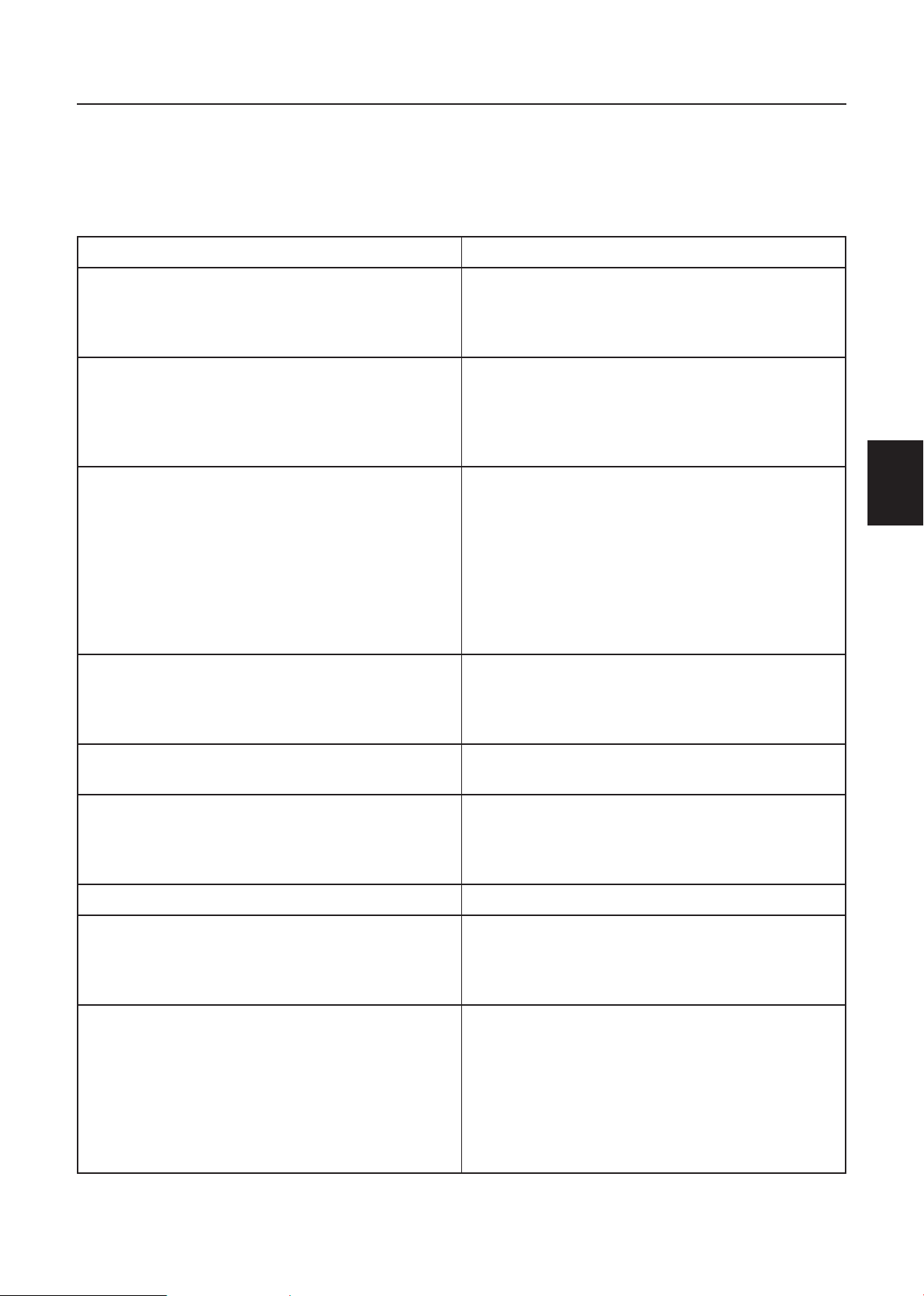
26
French
French
AVANT D’APPELER POUR UNE RÉPARATION
Veuillez procéder aux vérifications suivantes avant d’appeler pour une réparation. Ces conseils
peuvent vous faire gagner du temps et de l’argent puisque les prix pour l’installation du récepteur
et les réglages des commandes du client ne sont pas couverts sous votre garantie.
Symptômes Éléments à vérifier et actions à suivre
“ Fantôme “ ou image double * Ceci peut provenir d’une obstruction de l’antenne
due à des gratte-ciels ou des collines. L’image
peut être améliorer en utilisant une antenne
hautement directionnelle.
Absence de tension. * Vérifiez que le cordon d’alimentation ca du
téléviseur est branché dans la prise d’alimentation.
* Débranchez le téléviseur et attendez 60
secondes. Réinsérez ensuite la prise dans la prise
d’alimentation et rallumez le téléviseur.
Pas d’image * Vérifiez les connexions de l’antenne au dos du
téléviseur pour voir si elle est bien branchée sur
le téléviseur.
* Possibilité de problème de la station de diffusion.
Essayez une autre chaîne.
* Réglez les paramètres de luminosité et de
contraste.
* Vérifiez la commande des sous-titres. Certains
modes de TEXTE peuvent bloquer l’écran.
Bonne image, mais pas de son *Augmenter le VOLUME.
* Vérifiez que le son du téléviseur n’est pas coupé
; appuyez sur la touche MUTE (SILENCE) de la
télécommande.
Bon son, mais couleurs médiocres * Réglez les paramètres de luminosité, de contraste
et des couleurs.
Image médiocre * Parfois la qualité d’image est médiocre quand une
caméra ou un caméscope S-VHS est connecté à
votre TV ainsi qu’un autre périphérique en même
temps. Eteindre un des périphériques.
Image et son enneigés *Vérifiez les branchements de l’antenne.
Ligne pointillée horizontale * Ceci peut provenir d’interférences électriques
(par ex. : sèche-cheveux, lumières néon à
proximité, etc.)
*Éteignez l’appareil.
La télévision ne répond pas à la télécommande * Vérifiez si les piles fonctionnent. Remplacez-les si
nécessaire
* Nettoyez la lentille du capteur de la
télécommande sur le téléviseur.
* Vous pouvez toujours utiliser les boutons à l’avant
de votre téléviseur.
* Sélectionnez le mode TV pour être certain que
votre télécommande est en mode TV.
Page 56

French
27
French
GLOSSAIRE
HDTV
Les affichages en HDTV sont techniquement définis comme étant capables d’afficher des
lignes de balayage actives à au moins 720 p ou 1 080 i.
Entrées HDMI
Interface multimédia haute définition
Entrées Audio/Vidéo
Situés à l’arrière du récepteur, ces connecteurs (prise de type phono RCA) servent pour
l’entrée des signaux audio et vidéo. Conçus pour une utilisation avec des magnétoscopes
(ou autres accessoires) afin de recevoir une résolution d’image supérieure et d’offrir des
options de connexions sonores.
Menu
Une liste de fonctions à l’écran présentée sur l’écran de télévision est mise à la
disposition de l’utilisation pour procéder à des réglages.
MPAA
Motion Picture Association of America.
Multichannel Television sound
(MTS – son de télévision à chaînes multiples)
Le standard de diffusion, qui permet de transmettre le son stéréo avec l’image du
téléviseur.
RF
Radiofréquence ou conception de signal modulé qui sert de transporteur pour les
diffusions télévisées.
Second Audio Program (SAP – deuxième programme audio)
Une chaîne différente ou supplémentaire prévue dans le standard de diffusion du son de
télévision à chaînes multiples (Multichannel Television Sound - MTS). Une piste sonore
monaurale incluse au sein du signal enregistré ou vidéo (contenant généralement une
deuxième traduction de langue pour le programme affiché).
Minuterie de mise en sommeil
Vous pouvez définir une période au bout de laquelle le téléviseur s’éteindra
automatiquement.
Entrée S-Vidéo
Vous pouvez connecter votre poste de télévision sur une source vidéo de haute
résolution (comme un enregistreur de cassettes vidéo Super VHS, un lecteur de disques
laser et un ensemble de cinéma à domicile sur DVD) afin de procurer une satisfaction
maximale aux consommateurs.
Page 57

TABLA DE CONTENIDO
AVISO DE TRANSICIÓN A LA TELEVISIÓN DIGITAL .........................1
PARA SU SEGURIDAD ..................................................................................2
PRECAUCIONES Y RECORDATORIOS ...................................................3
INSTRUCCIONES IMPORTANTES DE SEGURIDAD ............................4
CONTENIDO DEL EMBALAJE ...................................................................5
PREPARACIÓN ................................................................................................ 6
COLOCACIÓN DE LA BASE ...............................................................................................6
PREPARACIÓN DE LA HDTV LCD PARA EL MONTAJE EN PARED .......................6
GUÍA DE CONEXIÓN DE PERIFÉRICOS ................................................8
INSTRUCCIONES DE FUNCIONAMIENTO ..........................................9
PARA UTILIZAR EL PANEL DE CONTROL FRONTAL ................................................9
UTILIZACIÓN DEL CONTROL REMOTO .................................................................... 10
VISUALIZACIÓN DE LAS ILUSTRACIONES DE LOS MODOS .............................. 11
CONEXIÓN DE LOS DISPOSITIVOS ............................................................................. 13
UTILIZACIÓN DE LOS MENÚS ....................................................................................... 19
MENÚ SETUP (CONFIGURACIÓN) ............................................................................... 19
MENÚ VIDEO (VIDEO) ....................................................................................................... 20
MENÚ AUDIO (AUDIO) ..................................................................................................... 20
MENU FEATURE (FUNCIONES) ...................................................................................... 21
CONSEJOS .............................................................................................................................. 24
ESPECIFICACIONES DEL PRODUCTO..................................................25
ANTES DE COMUNICARSE CON SERVICIO TÉCNICO .................26
Spanish
GLOSARIO .....................................................................................................27
Page 58

AVISO DE TRANSICIÓN A LA TELEVISIÓN DIGITAL
SA 1965
SA 1966
Este dispositivo contiene un sintonizador de televisión digital. Por lo tanto, podrá recibir programación
digital televisada por aire, con una antena adecuada, luego de que finalice la transmisión de alta
potencia de televisión analógica en los Estados Unidos el 17 de febrero de 2009. Algunos receptores
de televisión más antiguos, si dependen de una antena de TV, necesitarán un conversor de TV para
recibir programación digital por aire, pero seguirán funcionando igual que antes para otros propósitos
(por ejemplo, para visualizar estaciones de TV de baja potencia que siguen transmitiendo en analógico,
visualizar películas pregrabadas o utilizar videojuegos).
Para obtener más información,
comuníquese con la FCC al 1-888-CALL-FCC (1-888-225-5322)
o diríjase a www.DTV.gov. Para obtener más información acerca del programa de conversores de TV y
acerca de los cupones gubernamentales que se pueden utilizar para adquirir uno,
consulte www.dtv2009.gov
o comuníquese con el NTIA al 1-888-DTV-2009.
AVISO RELATIVO A LA TRANSICIÓN A TELEVISIÓN DIGITAL
Este equipo incorpora un sintonizador de televisión digital, lo que le permitirá recibir una programación
digital televisada por aire, con una antena adecuada, cuando se terminará la transmisión de alta potencia
de la televisión analógica en los Estados Unidos el 17 de febrero de 2009. Ciertos receptores de
televisión antiguos, si dependen de una antena de TV, necesitarán un conversor de TV para recibir por el
aire una programación digital, pero seguirán funcionando como antes para otros usos (por ejemplo para
ver emisoras de TV de baja potencia que todavía transmiten en analógico, para ver películas pregrabadas,
o para utilizar sus videojuegos).
Para obtener más información,
llame FCC 1-888-CALL-FCC (1-888-225-5322)
o refiérase a www.DTV.gov. Para toda información sobre el programa de conversores de
Spanish
TV, y acerca de los cupones del gobierno que se pueden usar
para comprarlos, refiérase a www.dtv2009.gov,
o llame al NTIA al 1-888-DTV-2009
SÍMBOLO DEFINICIÓN DEL SÍMBOLO
VOLTAJE PELIGROSO: el símbolo del relámpago con una punta
de flecha dentro del triángulo equilátero tiene la intención de alertar
al usuario acerca de la presencia de “voltaje peligroso” sin aislamiento
dentro de la carcasa del producto que podría tener la magnitud
suficiente como para constituirse en un riesgo de descarga eléctrico
para las personas.
INSTRUCCIONES: el signo de exclamación dentro del triángulo
equilátero indica al usuario la presencia de instrucciones de
funcionamiento y mantenimiento (reparación) en la documentación
que acompaña al producto.
No se debe exponer el producto a salpicaduras ni se debe colocar sobre éste ningún recipiente
que contenga agua, como por ejemplo, jarrones.
Precaución - Existe un riego de explosión si se coloca las pilas de forma incorrecta. Sólo
reemplace las pilas por unas del mismo tipo o equivalente.
1
Page 59

2
Spanish
Spanish
Hg
PARA SU SEGURIDAD
Antes de utilizar la TV, lea por completo este manual. Se deberá conservar este manual para su referencia
futura.
Declaración de interferencia de radiofrecuencia de clase B de la FCC
ADVERTENCIA:
(PARA MODELOS CERTIFICADOS POR LA FCC)
NOTA:
digital Clase B, conforme la Parte 15 de las Reglas de la FCC. Estos límites se crearon con el fin de
proporcionar una protección razonable contra interferencia dañina en una instalación residencial.
Este equipo genera, utiliza y puede irradiar energía de radiofrecuencia y, si no se encuentra instalado o si
no es utilizado de acuerdo con las instrucciones, puede causar interferencia dañina a las comunicaciones
radiales. Sin embargo, no se puede garantizar que la interferencia no ocurrirá en una instalación en
particular. En el caso de que el dispositivo causara interferencia dañina a las comunicaciones radiales, la
cual puede ser determinada encendiendo o apagando el dispositivo, se sugiere que el usuario tome una
o más de las siguientes medidas:
1. Reoriente o coloque en otro lugar la antena receptora.
2. Incremente la separación entre el equipo y el receptor.
3. Enchufe el equipo a un tomacorriente diferente del que se encuentra enchufado el receptor.
4.
este equipo ha sido comprobado y se determinó que cumple con los límites de dispositivo
Consulte a un vendedor o técnico experimentado de radio/TV para obtener ayuda.
AVISO
1. Los cambios o las modificaciones no aprobadas de forma explícita por la parte responsable del
cumplimiento podrían anular la autoridad del usuario de utilizar este dispositivo.
2. Se deben utilizar cables de interfaz y de alimentación CA blindados, si existiese alguno, con el fin de
cumplir con los límites de emisión.
3. El fabricante no es responsable de ninguna interferencia de radio o TV causada por una modificación
no autorizada de este equipo. Es responsabilidad del usuario corregir dicha interferencia.
ADVERTENCIA:
Para evitar incendios o un peligro de descarga eléctrica, no exponga la TV a la lluvia o humedad. Existen
voltajes peligrosamente altos dentro de la TV. No abra la cubierta de la TV. Remita el servicio técnico
sólo al personal de servicio técnico calificado.
SEGURIDAD: Desecho de la lámpara
LA LÁMPARA(S) QUE SE ENCUENTRA DENTRO DE ESTE PRODUCTO CONTIENE
MERCURIO Y DEBERÁ SER RECICLADA O DESECHADA DE ACUERDO CON LAS LEYES LOCALES,
ESTADUALES Y FEDERALES. PARA OBTENER MÁS INFORMACIÓN, PÓNGASE EN CONTACTO
CON LA ALIANZA DE INDUSTRIAS ELECTRÓNICAS EN WWW.EIAE.ORG.
Page 60

Spanish
3
Spanish
PRECAUCIONES Y RECORDATORIOS
1
2
3
4
5
6
7
8
9
0
1
2
3
4
5
6
7
8
9
0
1
2
3
4
5
6
7
8
9
0
Coloque la unidad en
superficies niveladas.
Desenchufe de inmediato
si existe un funcionamiento
defectuoso como una
desaparición de imagen, una
desaparición de video/audio,
humo u olores extraños
provenientes de la TV.
No arroje ningún objeto
dentro de la TV como
metales u otros materiales
inflamables.
Desenchufe de inmediato si
se colocan otros materiales
extraños dentro de la TV o
si ésta se cae.
Prohíba/evite abrir la
cubierta de la TV.
Recuerde desenchufar el
cable de alimentación CA
del tomacorriente CA antes
de efectuar la limpieza. No
utilice limpiadores líquidos
o en aerosol para limpiar la
pantalla.
No cubra ni bloquee
cualquier rejilla y abertura.
Una ventilación inadecuada
podría acortar la vida
útil de la TV y causar un
sobrecalentamiento.
Evite exponer la TV a la
luz solar directa y a lugares
polvorientos, de gran
humedad y humosos.
Póngase en contacto con el
personal de servicio técnico
para limpiar la parte interna
de la TV una vez por año.
No coloque la TV en
lugares cerrados o en una
caja cuando esté siendo
utilizada.
Aviso para el control remoto
Evite que se caiga
Asegúrese de desenchufar la
unidad cuando no se utilice
la TV durante un período de
tiempo extenso (días).
Evite que esté expuesto a
líquido
No coloque la TV cerca de
agua, por ejemplo, en lugares
como bañeras, lavabos,
fregaderos, lavaderos,
piscinas o subsuelos
mojados.
Evite utilizar limpiadores en
aerosol
Page 61

4
Spanish
Spanish
INSTRUCCIONES IMPORTANTES DE SEGURIDAD
Lea esta sección antes de utilizar la TV
1. Lea estas instrucciones.
2. Conserve estas instrucciones.
3. Preste atención a todas las advertencias.
4. Siga todas las instrucciones.
5. No utilice la TV cerca de agua.
6. Limpie la TV sólo con un paño seco.
7. No bloquee ninguna de las aberturas de ventilación. Instale la TV de acuerdo con las
instrucciones del fabricante.
8. No instale la TV cerca de cualquier fuente de calor como calentadores, registradores de
calor, estufas u otros dispositivos (incluyendo amplificadores) que emanen calor.
9. No intente anular las previsiones de seguridad del enchufe polarizado o del tipo con
conexión a tierra. Un enchufe polarizado posee dos clavijas, una más ancha que la otra. Un
enchufe del tipo con conexión a tierra posee 2 clavijas y una tercera clavija de conexión a
tierra. Se proporciona la clavija más ancha y la tercera clavija para su seguridad. Si el enchufe
proporcionado no puede ser colocado en el tomacorriente, consulte a un electricista para el
reemplazo del tomacorriente obsoleto.
10. Evite que el cable de alimentación sea pisado o estrangulado, especialmente en el enchufe,
receptáculos de conveniencia y en el lugar donde sale de la TV.
11. Sólo utilice los accesorios especificados por el fabricante.
12. Sólo utilice el carro, base, trípode, soporte o mesa especificado por el fabricante o vendido
junto con la TV. Cuando se utiliza un carro, tenga cuidado cuando mueva la combinación
carro/TV con el fin de evitar lesiones causadas por caídas.
13. Se deberá utilizar la TV sólo con el tipo de energía eléctrica que aparece en la etiqueta. Si no
está seguro acerca del tipo de energía eléctrica suministrado a su hogar, póngase en contacto
con el vendedor o con la empresa de energía eléctrica local.
14. Desenchufe la TV durante tormentas eléctricas o cuando no será utilizada durante períodos de
tiempo extensos.
15. Remita todo servicio técnico al personal de servicio técnico calificado. Se deberá efectuar
el servicio técnico cuando la TV se encuentre dañada de alguna forma, como por ejemplo,
cuando el cable o enchufe de alimentación se encuentre dañado, cuando se haya derramado
líquido o se haya caído un objeto dentro de la TV, cuando la TV haya sido expuesta a la lluvia
o humedad, cuando la TV funcione de forma anormal o cuando la TV se haya caído.
16. Este producto puede contener plomo o mercurio. El desecho de estos materiales podría
estar regulado conforme consideraciones medioambientales. Para obtener información acerca
del desecho o reciclaje, póngase en contacto con las autoridades locales o con la Alianza de
Industrias Electrónicas: www.eiae.org.
17. Daños que requieren la realización de servicio técnico – La TV deberá ser revisada por el
personal de servicio técnico cuando:
A. El cable de alimentación o el enchufe se encuentren dañados.
B. Se cayeron objetos o se derramó líquido en la TV.
C. Se expuso la TV a la lluvia.
D. La TV parece no funcionar de forma normal o exhibe un cambio pronunciado en el
rendimiento.
E. La TV se cayó o la cubierta de la TV se encuentra dañada.
18. Inclinación/estabilidad – Todas las TV deben cumplir con los estándares de seguridad
Page 62

Spanish
5
Spanish
internacionales recomendados en lo que respecta a la inclinación y estabilidad del diseño de
ANTENNA
ANTENNA DISCHARGE UNIT
GROUNDING CONDUCTORS
POWER SERVICE GROUNDING ELECTRODE SYSTEM
GROUND CLAMPS
ELECTRIC SERVICE E QUIPMENT
GROUND CLAMP
la cubierta de la TV.
No afecte estos estándares de diseño aplicando una fuerza excesiva en la parte frontal o
●
superior de la cubierta de la TV, que podría llegar a volcar el producto.
Además, no se ponga en peligro ni ponga en peligro a los niños colocando equipos/
●
juguetes electrónicos sobre la cubierta de la TV. Estos elementos podrían caerse
repentinamente desde la parte superior de la TV y causar daños en el producto y/o
lesiones personales.
19. Montaje en pared o techo – Se deberá montar la TV en la pared o techo sólo siguiendo
las recomendaciones del fabricante.
20. Líneas de tensión – Se deberá instalar la antena exterior alejada de líneas de tensión.
21. Conexión a tierra de la antena exterior – ISi se conecta una antena exterior al
receptor, asegúrese de que el sistema de antena posea una conexión a tierra con el fin de
proporcionar protección contra sobretensiones de voltaje y acumulación de cargas estáticas.
La Sección 810 del Código Eléctrico Nacional, ANSI/NFPA Núm. 70-1984, brinda
información con respecto a la conexión a tierra adecuada de los mástiles y la estructura de
soporte, la conexión a tierra del cable a una unidad de descarga de antena, el tamaño de
los conductores de tierra, la ubicación de la unidad de descarga de la antena, la conexión a
electrodos de tierra y los requisitos del electrodo de tierra. Consulte la figura que aparece a
continuación.
22. Entrada de objetos y líquidos – Se deberá tener cuidado a fin de que no se caigan
CONTENIDO DEL EMBALAJE
EJEMPLO DE LA CONEXIÓN A TIERRA DE LA ANTENA CONFORME EL CÓDIGO
ELÉCTRICO NACIONAL
Nota para instaladores del sistema de CATV: Se proporciona este recordatorio para llamar
la atención de los instaladores del sistema de CATV en lo que respecta al Artículo 820-40
del NEC (Código Eléctrico Nacional) que brinda directivas para la conexión a tierra correcta y,
en particular, especifica que se deberá conectar el cable a tierra al sistema de conexión a
tierra de la edificación lo más cerca del punto de entrada del cable como sea posible.
¡Asegúrese de enchufar el cable de alimentación en el tomacorriente luego de conectar la
TV al adaptador!
objetos ni se derramen líquidos en la cubierta de la TV a través de las aberturas.
TV AOC L47H861
●
Control remoto
●
2 pilas (“AAA”) para el control remoto
●
Base
●
4 tornillos (para sujetar la base al soporte)
●
Cable de corriente
●
Manual del usuario
●
Guía de configuración rápida
●
Page 63

6
Spanish
Spanish
PREPARACIÓN
IMPORTANTE: no aplique presión en el área de la pantalla debido a que podría afectar la
integridad de la misma. La garantía del fabricante no cubre abusos o instalaciones inadecuadas
por parte del usuario.
COLOCACIÓN DE LA BASE
IMPORTANTE: se deberá colocar la base de la HDTV antes de utilizarla..
1. Coloque la TV hacia abajo sobre una superficie suave
y plana (manta, goma espuma, paño, etc.) para evitar
cualquier daño a la HDTV.
2. Alinee e inserte cuidadosamente la base en el soporte.
3. Presione con delicadeza la base hacia la HDTV hasta
que el mecanismo de bloqueo quede asegurado en su
lugar.
4. Inserte los tornillos suministrados en la parte inferior
de la base.
5. Utilice un destornillador para ajustar la base al soporte.
PREPARACIÓN DE LA HDTV LCD PARA EL MONTAJE EN PARED
Sugerimos que mantenga la TV a como mínimo 2,36 pulgadas (60 mm) de la pared con el fin de
evitar una interferencia del cable.
Antes de montar la TV en la pared, deberá extraer la base.
Para colocar un soporte de montaje en pared en la TV:
1 Quite los dos tornillos T4 y los 4 tornillos M4 que sostienen la base al pie de apoyo.
2 Sujete el soporte de montaje en la pared a la parte trasera de la TV con seis tornillos M4,
como se indica en la imagen.
NOTA:
no se incluye el soporte de montaje en pared de 400mm x 200mm ni los tornillos M6.
Page 64

Spanish
7
Spanish
POWER
VIDEO COMP PC/HDMI TV
Power Key
Min
1 m
¡Asegúrese de enchufar el cable de
alimentación en el tomacorriente luego de
conectar el cable de alimentación en la TV!
1. Instale la base. Coloque la TV sobre
una supercie sólida.
Asegúrese de que la TV esté colocada en
una ubicación donde el aire pueda fluir
libremente. No cubra las aberturas de
ventilación ubicadas en la cubierta trasera.
Para evitar cualquier situación insegura,
no se deberá colocar sobre o cerca de la
TV ninguna fuente de llama expuesta tales
como velas encendidas.
Evite exponer la TV al calor, a la luz solar
directa y a la lluvia o agua. No se debe
exponer la TV a salpicaduras.
2. Conecte el cable de la antena o el cable
de CATV al conector de antena ANT IN
75Ω (ENTRADA DE ANTENA 75Ω)
ubicado en la parte trasera de la TV.
3. Control remoto:
Extraiga la tapa del compartimiento de las
pilas. Inserte las 2 pilas suministradas (tipo
“AAA” de 1,5V).
4. Alimentación:
Inserte el cable de alimentación en un
tomacorriente de pared que posea un
suministro de alimentación CA. Podrá
visualizar los estados del indicador LED
en el panel frontal. Si el indicador LED
se enciende de color azul, esto significa
que la TV se encuentra encendida. Si el
indicador LED se enciende de color rojo,
esto significa que la TV se encuentra en el
modo de espera.
5. Encendido de la TV:
Presione el botón POWER (Encendido/
Apagado) en el control remoto o en el
panel frontal.
La TV se encenderá en un minuto y podrá
visualizar imágenes en la pantalla.
Botón Power (Encendido/Apagado)
Page 65

8
Spanish
Spanish
GUÍA DE CONEXIÓN DE PERIFÉRICOS
3
AC POWER
1. HDMI – Conecte la fuente primaria para video digital como un reproductor multimedia de
DVD o decodificador a través de este conector totalmente digital. La banda de color blanco
ubicada en la parte trasera de la TV indica esta conexión.
2. PC IN (ENTRADA DE PC) – Conecte aquí los cables de audio y video de una computadora.
3. AV/S-VIDEO IN (ENTRADA AUDIO/VIDEO/S-VIDEO) – Conecte la fuente primaria
para dispositivos de video compuesto tales como una videograbadora o una consola de
videojuegos. Utilice los conectores blanco y rojo para conectar el audio externo desde la
misma fuente. La señal transmitida por el cable y conector de S-Video, si está conectado,
tendrá prioridad por sobre el conector de video RCA (conector amarillo).
4. COMPONENT (VIDEO COMPONENTE) (YPb/CbPr/Cr con audio L/R)
– Conecte aquí la fuente primaria para dispositivos de video componente como un
reproductor de DVD o un decodificador. De izquierda a derecha, utilice rojo para la entrada
Pr, azul para la entrada Pb, verde para la entrada Y, rojo para la entrada de audio derecho (R)
y blanco para la entrada de audio izquierdo (L).
5. DTV – Conecte este puerto con una antena o cable digital (proveniente desde la pared y no
desde el decodificador) para TV digital.*
6. SPDIF (Salida de audio digital óptica) - Cuando una señal de audio digital está asociada
con la entrada seleccionada para la visualización, el audio digital estará disponible en esta
conexión SPDIF con el sistema de cine en casa.
Una vez que los dispositivos estén conectados, utilice el siguiente procedimiento para visualizar la señal de
entrada:
Presione el botón de la fuente en el control remoto para seleccionar la fuente que desea
visualizar. (Por ejemplo: presione el botón VIDEO (VIDEO) para seleccionar “Composite Rear”
(“Video compuesto trasero”) si conectó una videograbadora al conector de video compuesto
trasero).
Page 66
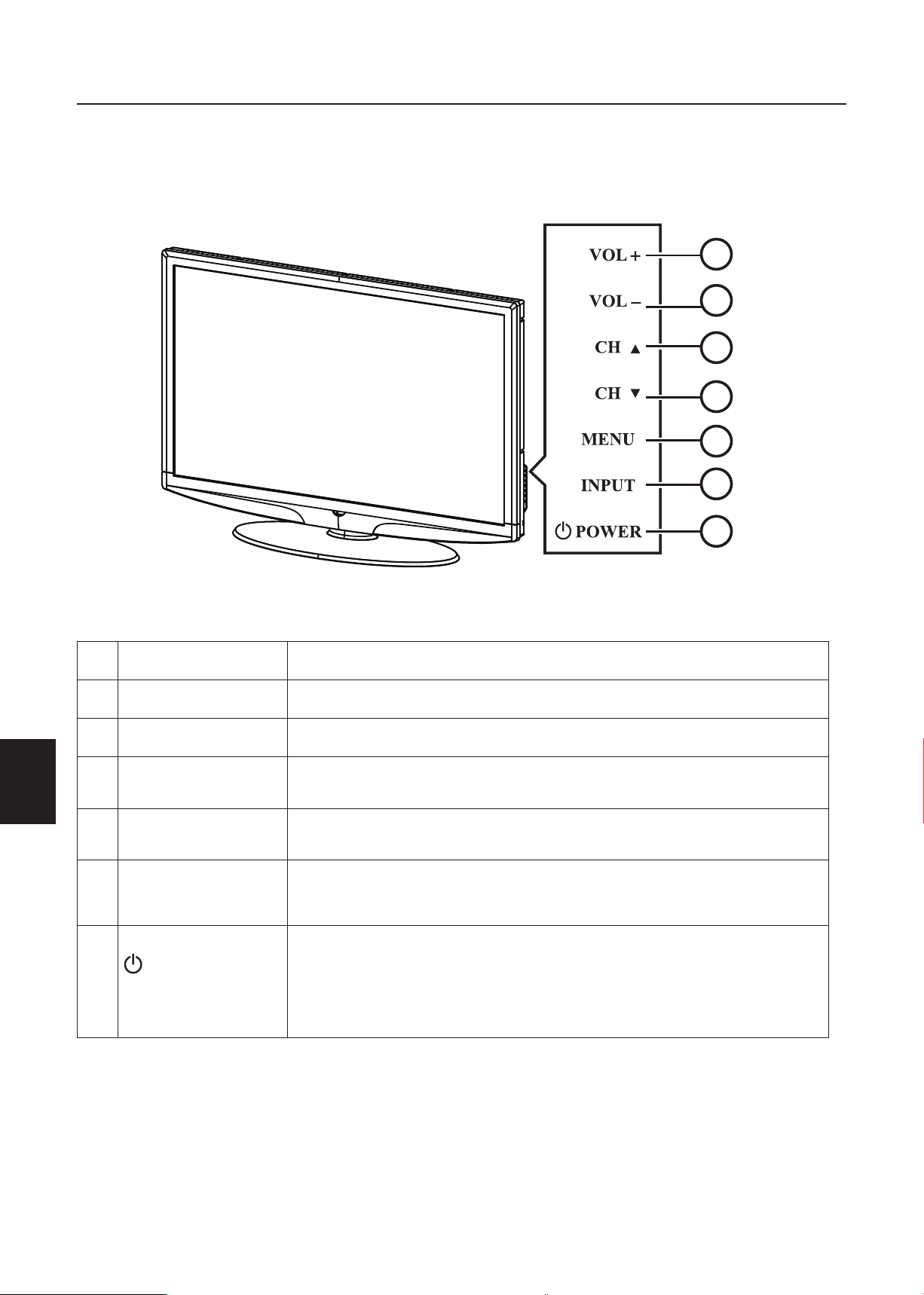
Spanish
9
Spanish
INSTRUCCIONES DE FUNCIONAMIENTO
1
2
3
5
6
4
7
PARA UTILIZAR EL PANEL DE CONTROL FRONTAL
1 VOL + VOL +: Presione este botón para subir el nivel de volumen. .
2. VOL - VOL - : Presione este botón para subir el nivel de volumen.
3. CH
4. CH
5. MENU (MENÚ)
6.
7.
▲
▼
INPUT
(ENTRADA)
POWER
(ENCENDIDO/
APAGADO)
▲
CH : Presione este botón para bajar el nivel de volumen.
CH : Presione este botón para seleccionar el número de
▼
programa anterior.
Botón Menu (Menú): Presione este botón para ingresar o salir
del menú OSD.
Botón Source (Fuente): Presione este botón para seleccionar
la fuente de entrada.
Botón Power (Encendido/Apagado): Presione este botón
para encender/apagar (modo de espera) la TV. (Vuelva a encender
la TV luego de que el indicador LED de encendido/apagado
aparezca de color rojo y haya dejado de parpadear).
Page 67

10
Spanish
Spanish
UTILIZACIÓN DEL CONTROL REMOTO
POWER
VIDEO
1 2 3
4 5 6
7 8 9
0
PRE CH
COMP PC/HDMI TV
SLEEP
FAV SOURCE
MUTE
MENU EXIT
ENTER
V-CHIP
VIDEO ADJ AUDIO ADJ
CC
DISPLAY
VOLCH
EPG
FREEZE MTS SAP
WIDE
RL57A
POWER (ENCENDIDO/APAGADO)
Presione este botón para ENCENDER/
APAGAR (modo de espera) la TV.
(Nota: 1. La TV nunca está apagada
por completo a menos que esté
desenchufada de forma física. 2.
Presione este botón para encender la
TV luego de que el indicador LED de
encendido/apagado aparezca de color
rojo y haya dejado de parpadear).
VIDEO
Presione este botón varias veces para
seleccionar el modo de fuente de
S-Video/video compuesto.
COMP (VIDEO COMPONENTE)
Presione este botón varias veces para
seleccionar el modo de fuente de video
componente.
PC/HDMI
Presione este botón varias veces para
seleccionar el modo de fuente de VGA
o HDMI.
TV
Presione este botón para seleccionar el
modo de fuente de ATSC/NTSC TV.
Botones numéricos 0 ~ 9 /-
Presione estos botones para ingresar
el número de canal de TV para
seleccionar el canal (Presione ‘-’ para
seleccionar un subcanal).
SLEEP (TEMPORIZADOR DE
APAGADO)
Presione este botón para establecer
el temporizador de apagado (off
(desactivado)/5 min/10 min/15 min/30
min/45 min/60 min/90 min/120 min/180
min/240 min) luego del cual la TV
ingresará automáticamente en el modo
de espera.
FREEZE (CONGELAR)
Presione este botón para congelar la
imagen visualizada.
CH-/ CH +
Presione + o – para navegar a través de
los canales de TV.
MENU (MENÚ)
Presione este botón para ingresar o
salir del menú OSD.
“<”,“>”,“<”,“>”,“ENTER (ACEPTAR)
Presione este botón para ajustar los
diferentes elementos de las funciones
del menú.
PREV CH (CANAL ANTERIOR)
Presione este botón para visualizar el
canal anterior.
MTS/SAP
Presione este botón para activar los
diferentes modos de audio de NTSC
TV: Stereo (Estéreo), SAP (SAP)
o Mono (Mono). También puede
seleccionar idiomas de DTV.
WIDE (PANTALLA ANCHA
Presione este botón para seleccionar
el aspecto de visualización: Normal
(Normal), Wide (Pantalla ancha),
Zoom (Zoom) o Cinema (Cine).
SOURCE (FUENTE)
Presione este botón varias veces para
seleccionar las diferentes fuentes de
entrada
EPG
Esta función no se encuentra
soportada.
MUTE (SILENCIAR)
Activa/desactiva el sonido.
DISPLAY (VISUALIZAR)
Presione este botón para mostrar
información sobre la fuente de
entrada, canal de TV, resolución de la
pantalla y hora actual.
VOL- / VOL+
Presione + o – para ajustar el
volumen.
EXIT (SALIR)
Presione este botón para salir del
menú OSD.
V-CHIP
Presione este botón para activar/
desactivar el control paterno de forma
temporal. (Luego de establecer la tabla
de restricciones de la clasificación de
MPAA o TV).
VIDEO ADJ (AJUSTE DE VIDEO)
Presione este botón para seleccionar
el ajuste de brillo o contraste.
AUDIO ADJ (AJUSTE DE
AUDIO)
Presione para seleccionar Bajos y
agudos.
CC
Presione varias veces este botón
para cambiar el tipo de closed
caption (subtítulos ocultos) entre
CC ON (CC ACTIVADO)/CC OFF
(CC DESACTIVADO)/CC ON
WHEN MUTE (CC ACTIVADO AL
SILENCIAR).
FAVORITE (CANALES
FAVORITOS)
Presione este botón para cambiar
entre el modo Canales favoritos/
Normal.
Page 68

Spanish
11
Spanish
VISUALIZACIÓN DE LAS ILUSTRACIONES DE LOS MODOS
Modo normal en una pantalla de 16:9
El contenido original aparecerá en el centro
de la pantalla.
Modo de pantalla ancha en una pantalla
de 16:9
En este modo, el contenido original cubrirá el
ancho entero horizontal de la pantalla.
Modo de pantalla ancha en una pantalla de
16:10
Se utiliza Pantalla ancha1 y Pantalla ancha2:
Pantalla ancha1: el contenido original
cubrirá la pantalla
completa al mismo
tiempo que se mantendrá
la relación correcta
del contenido 16:9. Es
necesario efectuar un
pequeño recorte del
contenido en ambos lados.
Pantalla ancha2: el contenido original
cubrirá el ancho de la
pantalla al mismo tiempo
que se mantendrá la
relación correcta del
contenido 16:9. Se agregan
pequeñas barras negras.
Page 69

12
Spanish
Spanish
Modo ZOOM en una pantalla de 16:9
En el caso de aquellas imágenes con formato de pantalla ancha que están programadas
originalmente en cuadros 4:3 con barras negras superiores e inferiores, este modo estirará la
imagen tanto en el ancho como en el alto para lograr una visualización completa de los datos
activos.
Imagen 16:9 en un cuadro 4:3 Misma imagen con el modo ZOOM
Modo ZOOM en una pantalla de 16:10
En el caso de aquellas imágenes con formato de pantalla ancha que están programadas
originalmente en cuadros 4:3 con barras negras superiores e inferiores, este modo estirará la
imagen tanto en el ancho como en el alto para lograr una visualización completa de los datos
activos. Es necesario realizar un pequeño recorte en ambos lados para lograr una visualización
completa.
Imagen 16:9 en un cuadro 4:3
Modo CINE en una pantalla de 16:9 o 16:10n
Este modo se aplica para visualizar el contenido en formato 2.35:1 en pantallas de 16:9. Se
recortan los lados derecho e izquierdo para mantener una relación no distorsionada de la
imagen.
Misma imagen con el modo ZOOM
NOTA
la TV AOC L47H861 posee 4 formatos de imagen: Normal (Normal), Wide (Pantalla
ancha), Zoom (Zoom) y Cinema (Cine).
Page 70

Spanish
13
Spanish
CONEXIÓN DE LOS DISPOSITIVOS
3. Encienda la HDTV.
Coaxial (RF)
Utilización de su antena o cable digital
para DTV.
1. Apague la HDTV.
2. Conecte el conector coaxial (RF) desde su
antena o cable digital (proveniente desde
la pared y no desde el decodificador) en
el conector ANTENNA/CABLE DIGITAL/
ANALOG (ANTENA/CABLE DIGITAL/
ANALÓGICO).
3. Encienda la HDTV.
4. Seleccione DTV utilizando el botón
SOURCE (FUENTE) en el control remoto,
panel de control lateral de la HDTV o
presionando directamente el botón TV en
el control remoto.
Utilización de su antena o cable para
DTV.
4. Seleccione TV utilizando el botón SOURCE
(FUENTE) en el control remoto, panel de
control lateral de la HDTV o presionando
directamente el botón TV en el control
remoto.
Utilización de la antena o cable para la
videograbadora
1. Apague la HDTV y la videograbadora.
2. Conecte el conector “Output to TV”
(“Salida a TV”), “RF Out” (“Salida RF”) o
“Antenna Out” (“Salida de la antena”)
ubicado en la parte trasera de la
videograbadora al conector ANTENNA/
CABLE DIGITAL/ANALOG (ANTENA/
CABLE DIGITAL/ANALÓGICO) ubicado
en la parte trasera de la HDTV.
3. Encienda la HDTV y la videograbadora.
4. Seleccione TV utilizando el botón SOURCE
(FUENTE) en el control remoto, panel de
control lateral de la HDTV o presionando
directamente el botón TV en el control
remoto.
1. Apague la HDTV.
2. Conecte el conector coaxial (RF) desde
su antena o cable (proveniente desde la
pared y no desde el decodificador) en el
conector ANTENNA/CABLE DIGITAL/
ANALOG (ANTENA/CABLE DIGITAL/
ANALÓGICO) ubicado en la parte trasera
de la HDTV.
NOTA
Isi posee una antena “off-air” o TV
por cable, realice la conexión con el
conector “Antenna In” (“Entrada de
antena”) ubicado en la parte trasera de
la videograbadora.
Conexión del decodicador de HDTV
Utilización de HDMI
Se deberán conectar los decodificadores de
HDTV que poseen una interfaz digital HDMI
a la entrada HDMI de la HDTV LCD para
obtener resultados óptimos.
Page 71

14
Spanish
Spanish
Conexión del decodicador de HDTV
(Óptima)
1. Apague la HDTV y el decodificador de
HDTV.
2. Conecte un extremo del cable HDMI a la
salida HDMI del decodificador HDTV y el
otro extremo a la entrada HDMI ubicada
en la parte trasera de la HDTV.
3. Encienda la HDTV y el decodificador de
HDTV.
4. Seleccione HDMI utilizando el botón
SOURCE (FUENTE) en el control remoto,
panel de control lateral de la HDTV o
presionando directamente el botón HDMI
en el control remoto.
3. Encienda la HDTV y el decodificador de
HDTV.
4. Seleccione HDMI utilizando el botón
SOURCE (FUENTE) en el control remoto,
panel de control lateral de la HDTV o
presionando directamente el botón HDMI
en el control remoto.
NOTA
La entrada HDMI de la HDTV soporta la
Protección de Contenido de Digital de
Ancho de Banda Elevado (HDCP). HDCP
encripta la transmisión entre la fuente de
video y la pantalla digital para lograr una
mayor seguridad y protección.
Consulte el manual de usuario del
decodificador de HDTV para obtener más
información acerca de los requisitos de
salida de video del producto o póngase en
contacto con el operador de TV por cable
o TV satelital.
La conexión DVI a HDMI sólo proporciona
video. Se requiere efectuar una conexión
con un reproductor de audio alternativo
para obtener audio.
NOTA
La entrada HDMI de la HDTV soporta la
Protección de Contenido de Digital de
Ancho de Banda Elevado (HDCP). HDCP
encripta la transmisión entre la fuente de
video y la pantalla digital para lograr una
mayor seguridad y protección.
Consulte el manual de usuario del
decodificador de HDTV para obtener más
información acerca de los requisitos de
salida de video del producto o póngase en
contacto con el operador de TV por cable
o TV satelital.
Para decodicadores de HDTV con DVI
1. Apague la HDTV y el decodificador de
HDTV.
2. Por medio de un cable HDMI-DVI, conecte
el extremo DVI al decodificador de HDTV
y el extremo HDMI a la entrada HDMI
ubicada en la parte trasera de la HDTV.
Utilización de video componente
Conexión del decodicador de HDTV
(Buena):
1. Apague la HDTV y el decodificador de
HDTV.
2. Conecte el conector Pr (color rojo) del
decodificador de HDTV al conector Pr
(color rojo) correspondiente en el grupo
Component (Video componente).
3. Conecte el conector Pb (color azul) del
decodificador de HDTV al conector Pb
(color azul) correspondiente en el grupo
Component (Video componente).
Page 72

Spanish
15
Spanish
4. Conecte el conector Y (color verde) del
decodificador de HDTV al conector Y
(color verde) correspondiente en el grupo
Component (Video componente).
5. Por medio de un cable de audio
(conectores rojo y blanco), conecte
un extremo del cable a los conectores
de salida de audio de la salida de video
componente del decodificador de HDTV y
conecte el otro extremo a los conectores
de audio de la entrada de audio de la
HDTV.
6. Encienda la HDTV y el decodificador de
HDTV.
7. Seleccione Component (Video
componente) (Video 3) utilizando el botón
SOURCE (FUENTE) en el control remoto,
panel de control lateral de la HDTV
o presionando directamente el botón
Component (Video componente) en el
control remoto.
la parte trasera de la HDTV.
3. Utilizando los conectores rojo y
blanco, conecte un extremo del cable
a los conectores de salida de audio
correspondiente a la salida de video
ubicada en el decodificador y el otro
extremo en los conectores de audio de
la entrada AV (Audio/Video) ubicada en la
parte trasera de la HDTV.
4. Encienda la HDTV y el decodificador.
5. Seleccione Composite (Video compuesto)
(Video 1) utilizando el botón SOURCE
(FUENTE) en el control remoto, panel de
control lateral de la HDTV o presionando
directamente el botón AV (Audio/Video)
en el control remoto.
Utilización de coaxial (RF)
NOTA
Consulte el manual de usuario del de-
codificador de HDTV para obtener más
información acerca de los requisitos de
salida de video del producto o póngase en
contacto con el operador de TV por cable
o TV satelital.
Conexión del decodicador básico
Utilización de video compuesto
1. Apague la HDTV y el decodificador.
2. Por medio de un cable coaxial (RF),
conecte un extremo del cable a la salida
TV OUT (SALIDA DE TV) (RF) ubicada
en el decodificador y el otro extremo en
la entrada DTV/TV ubicada en la parte
trasera de la HDTV.
3. Encienda la HDTV y el decodificador.
4. Seleccione TV utilizando el botón SOURCE
(FUENTE) en el control remoto, panel de
control lateral de la HDTV o presionando
directamente el botón TV (ubicado debajo
del botón WIDE (PANTALLA ANCHA))
en el control remoto.
1. Apague la HDTV y el decodificador.
2. Por medio de un cable de AV (Audio/
Video), conecte el conector de video (color
amarillo) del decodificador con el conector
de video correspondiente (color amarillo)
en el grupo AV (Audio/Video) ubicado en
NOTA
Consulte el manual de usuario del de-
codificador para obtener más información
sobre cómo seleccionar la salida de video
o RF en el producto..
Page 73
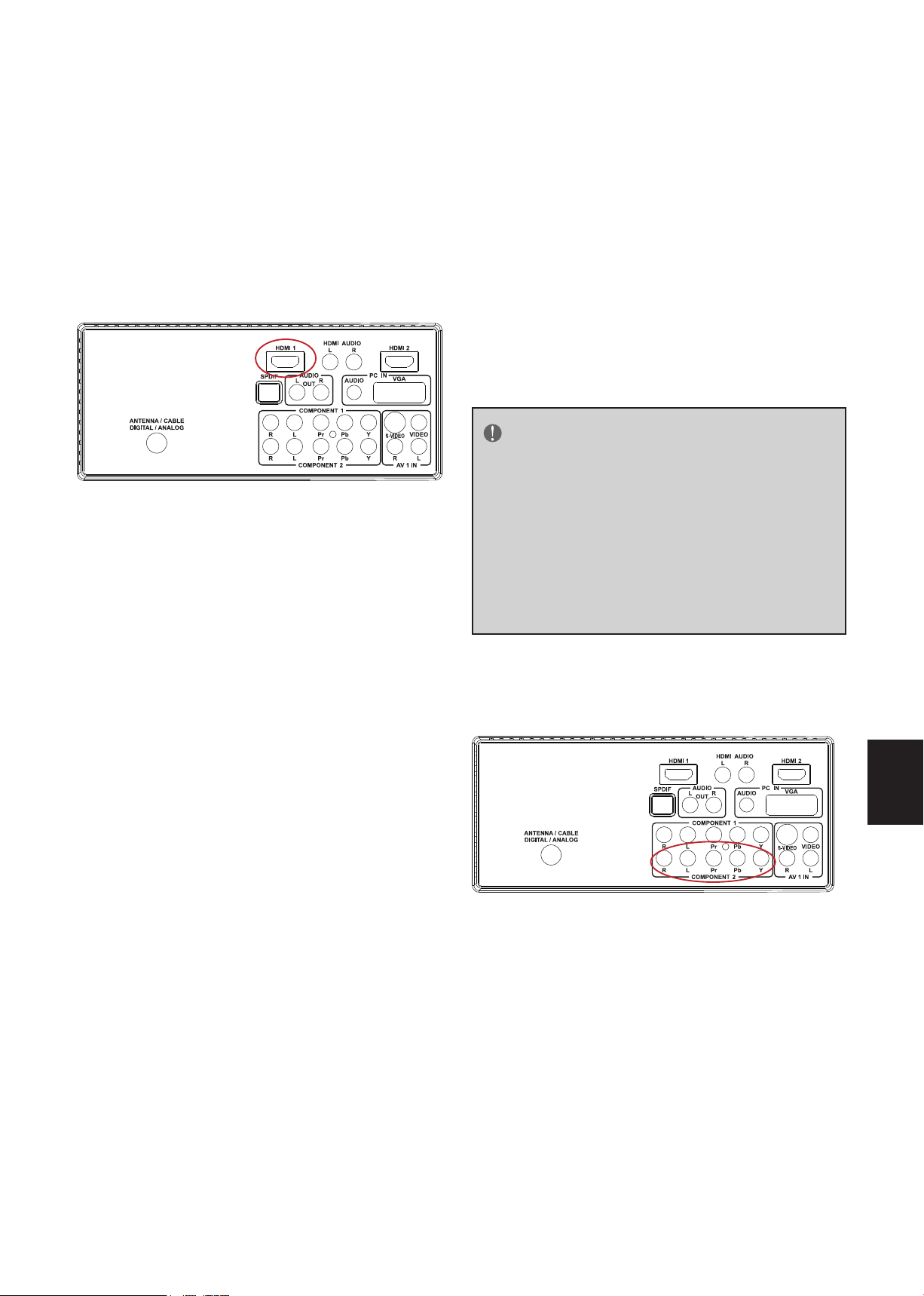
16
Spanish
Spanish
Conexión del reproductor de DVD
Para reproductores de DVD con DVI:
Utilización de HDMI
Se deben conectar los reproductores de DVD
que poseen una interfaz digital como HDMI
(Interfaz Multimedia de Alta Definición) a la
entrada HDMI ubicada en la HDTV LCD para
obtener resultados óptimos.
Conexión del reproductor de DVD
(Óptima)
1. Apague la HDTV y el reproductor de DVD.
2. Conecte un extremo del cable HDMI a la
salida HDMI del reproductor de DVD y el
otro extremo a la entrada HDMI ubicada
en la parte trasera de la HDTV.
1. Apague la HDTV y el reproductor de DVD.
2. Por medio de un cable HDMI-DVI, conecte
el extremo DVI al reproductor de DVD
y el extremo HDMI a la entrada HDMI
ubicada en la parte trasera de la HDTV.
3. Encienda la HDTV y el reproductor de
DVD.
4. Seleccione HDMI utilizando el botón
SOURCE (FUENTE) en el control remoto,
panel de control lateral de la HDTV o
presionando directamente el botón HDMI
en el control remoto.
NOTA
Consulte el manual de usuario del repro-
ductor de DVD para obtener más información acerca de los requisitos de salida
de video del producto.
La conexión DVI a HDMI sólo proporciona
video. Se requiere efectuar una conexión
con un reproductor de audio alternativo
para obtener una salida de audio.
3. Encienda la HDTV y el reproductor de
DVD.
4. Seleccione HDMI utilizando el botón
SOURCE (FUENTE) en el control remoto,
panel de control lateral de la HDTV o
presionando directamente el botón HDMI
en el control remoto.
Utilización de video componente
Conexión del reproductor de DVD (Buena)
1. Apague la HDTV y el reproductor de DVD.
2. Conecte el conector Pr (color rojo) del
reproductor de DVD al conector Pr
(color rojo) correspondiente en el grupo
Component (Video componente) ubicado
en la parte trasera de la HDTV.
3. Conecte el conector Pb (color azul) del
reproductor de DVD al conector Pb
(color azul) correspondiente en el grupo
Component (Video componente) ubicado
en la parte trasera de la HDTV.
Page 74

Spanish
17
Spanish
4. Conecte el conector Y (color verde)
del reproductor de DVD al conector Y
(color verde) correspondiente en el grupo
Component (Video componente) ubicado
en la parte trasera de la HDTV.
5. Por medio de un cable de audio (conectores
rojo y blanco), conecte un extremo del
cable a los conectores de salida de audio
de la salida de video componente del
reproductor de DVD y conecte el otro
extremo a los conectores de audio de la
entrada de audio de la HDTV.
6. Encienda la HDTV y el reproductor de DVD.
7. Seleccione Component (Video
componente) utilizando el botón SOURCE
(FUENTE) en el control remoto, panel de
control lateral de la HDTV o presionando
directamente el botón Component (Video
componente) en el control remoto.
NOTA
Consulte el manual de usuario del
reproductor de DVD para obtener más
información acerca de los requisitos de
salida de video del producto.
4. Encienda la HDTV y el reproductor de
DVD.
5. Seleccione S-Video (Video 2) utilizando el
botón SOURCE (FUENTE) en el control
remoto, panel de control lateral de la
HDTV o presionando directamente el
botón AV (Audio/Video) en el control
remoto.
Utilización de video compuesto (AV)
Conexión del reproductor de DVD (Buena)
1. Apague la HDTV y el reproductor de DVD.
2. Conecte el conector de video (color
amarillo) del reproductor de DVD al
conector de video (color amarillo) ubicado
en el grupo AV (Audio/Video) ubicado en
la parte trasera de la HDTV.
Utilización de S-Video (AV)
Conexión del reproductor de DVD (Buena):
1. Apague la HDTV y el reproductor de DVD.
2. Conecte el conector S-Video ubicado en la
parte trasera del reproductor de DVD con
el conector de entrada de S-Video ubicado
en el grupo AV (Audio/Video) ubicado en
la parte trasera de la HDTV.
3. Conecte un extremo del cable de
audio (conectores rojo y blanco) a los
conectores de salida de audio de la salida
de S-Video del reproductor de DVD y
conecte el otro extremo a los conectores
de audio de la entrada AV (Audio/Video)
ubicada en la parte trasera de la HDTV.
3. Conecte los conectores de audio R (color
rojo) y L (color blanco) del reproductor
de DVD con los conectores de entrada de
audio correspondientes R (color rojo) y L
(color blanco) del grupo AV (Audio/Video)
ubicado en la parte trasera de la HDTV.
4. Encienda la HDTV y el reproductor de
DVD.
5. Seleccione Composite (Video compuesto)
(Video 1) utilizando el botón SOURCE
(FUENTE) en el control remoto, panel de
control lateral de la HDTV o presionando
directamente el botón AV (Audio/Video)
en el control remoto.
Page 75

18
Spanish
Spanish
Conexión de la videograbadora o la
cámara de videoa
Conexión con una PC
1. Apague la HDTV y la PC.
1. Apague la HDTV y la videograbadora o la
cámara de video.
2. Conecte el conector S-Video ubicado en
la parte trasera de la videograbadora o
la cámara de video con el conector de
entrada de S-Video ubicado en el grupo AV
(Audio/Video) ubicado en la parte trasera
de la HDTV.
3. Conecte un extremo del cable de
audio (conectores rojo y blanco) a los
conectores de salida de audio de la
salida de S-Video de la videograbadora
o la cámara de video y conecte el otro
extremo a los conectores de audio de la
entrada AV (Audio/Video) ubicada en la
parte trasera de la HDTV.
4. Encienda la HDTV y la videograbadora o la
cámara de video.
5. Seleccione S-Video (Video 2) utilizando el
botón SOURCE (FUENTE) en el control
remoto, panel de control lateral de la
HDTV o presionando directamente el
botón AV (Audio/Video) en el control
remoto.
2. Conecte un extremo del cable D-Sub RGB
de 15 clavijas (VGA) a la salida RGB de la
PC y el otro extremo en la entrada PC IN
ubicada en la parte trasera de la HDTV.
3. Conecte la salida de audio de la
computadora con la entrada Audio de PC
IN ubicada en la parte trasera de la HDTV.
4. Encienda la HDTV y la PC.
5. Seleccione RGB (PC) utilizando el botón
SOURCE (FUENTE) en el control remoto,
panel de control lateral de la HDTV o
presionando directamente el botón PC/
HDMI en el control remoto.
NOTA
Para obtener la mejor calidad de imagen
cuando se realiza la conexión con una
computadora a través de la entrada PC
IN, establezca el modo de sincronización
de la computadora en la resolución nativa
del panel. Consulte la guía de usuario de
la computadora o la tarjeta gráfica para
obtener información adicional sobre cómo
establecer el modo de sincronización y sobre
los requisitos de salida de video del producto.
NOTA
Consulte el manual de usuario de la vid-
eograbadora o la cámara de video para
obtener más información acerca de los
requisitos de salida de video del producto.
Page 76

Spanish
19
Spanish
UTILIZACIÓN DE LOS MENÚS
Setup
Video
Audio
Feature
Tuning Band
DTV Signal
Auto Ch Search
Add On Ch Search
Manual Channel Set
Channel Labels
Menu Language
Aspect Ratio
Favorite Channel Mode
Enter
Exit
To SelectTo Move To Exit
Cable
English
Normal
Off
Pobre
Nivel de la señal
Normal Buena
95
1. Presione el botón MENU (MENÚ) para
visualizar el menú principal.
2. Utilice el cursor arriba/abajo para
seleccionar un ítem del menú.
3. Utilice el cursor izquierda/derecha para
ingresar en un submenú.
4. Presione el botón ENTER (ACEPTAR)
para habilitar/deshabilitar la función.
5. Presione el botón MENU (MENÚ) o
EXIT (SALIR) para salir del menú.
3. Auto Ch Search (Búsqueda
automática de canales): permite buscar
automáticamente todos los canales de
NTSC / ATSC TV y almacenarlos en la tabla
de canales. En el proceso de búsqueda de
canales, el menú OSD mostrará la cantidad
de canales encontrados.
Presione el botón MENU (MENÚ) para
ingresar en el menú OSD (Menú de
visualización en pantalla) principal. Ajuste los
ítems del menú Setup (Configuración),
menú Video (Video), menú Audio (Audio)
y menú Feature (Funciones). Sin embargo,
algunos ítems de las funciones de los menús
sólo estarán disponibles en determinados
modos de fuentes.
MENÚ SETUP (CONFIGURACIÓN)
Se muestra a continuación el menú Setup
(Configuración) del modo TV. En otros modos
de fuentes, el menú Setup (Configuración) sólo
incluye los ítems Menu Language (Idioma
del menú) y Aspect Ratio (Relación de
aspecto).
4. Add on Ch search (Agregar en la
búsqueda de canales):agrega los canales
encontrados.
5. Manual Channel Set (Configuración
manual de canales): aparecerá la tabla de
configuración de canales. El usuario puede
seleccionar si desea visualizar canales de
ATSC o NTSC TV y, a continuación, editar
(agregar/eliminar) los números de canales.
6. Channel Labels (Etiquetas de canales):
muestra el menú de etiquetas de canales de
NTSC / ATSC TV que permite que el usuario
modifique específicamente las etiquetas de
canales.
7. Menu Language (Idioma del menú):
permite seleccionar el idioma de
visualización del menú. (Inglés / Español /
Francés).
1. Tuning Band (Banda de sintonización):
seleccione la señal de fuente de TV entre Air
(Aire) (antena) o Cable (Cable) (CATV).
2. DTV Signal (Señal de DTV): Show the
intensity of the received DTV signal.
8. Aspect Ratio (Relación de aspecto):
permite seleccionar la relación de aspecto
de la pantalla. (Normal / Zoom / Pantalla
ancha / Cine).
9. Favorite Channel Mode (Modo de
canales favoritos): Cuando el modo de
canales favoritos está habilitado, el usuario
puede editar la tabla de canales favoritos
en la opción de establecimiento de canales
favoritos.
Page 77

20
Spanish
Spanish
MENÚ VIDEO (VIDEO)
Setup
Video
Audio
Feature
Enter
To SelectTo Move To Exit
Exit
Contrast 50
50
0
50
0
10
Preset
Brightness
Sharpness
Color
Tint
Backlight
Settings
Setup
Video
Audio
Feature
Enter
To SelectTo Move To Exit
Exit
Bass
Audio Language
31
31
0
RAW
Default
On
Preset
Treble
Balance
Digital Audio Output
Off
Surround Sound
TV Speaker
Settings
MENÚ AUDIO (AUDIO)
En la mayoría de los modos de fuentes, el
menú Video (Video) es como se muestra a
continuación. Este menú proporciona varios
ítems de ajuste de video para que el usuario
ajuste la visualización de video. En los modos
de fuentes VGA, el menú Video (Video) sólo
incluye los ítems Contrast (Contraste),
Brightness (Brillo), Back light
(Retroiluminación) y Settings (Preset)
(Configuración (Preestablecida)).
Se muestra a continuación el menú Audio
(Audio) del modo TV. Este menú proporciona
un ajuste de video para permitir que el
usuario modifique la configuración de audio.
La configuración de idioma del audio sólo está
disponible con la fuente ATSC TV. Esta opción
está deshabilitada en los otros modos de
fuentes de entrada.
1. Contrast (Contraste): ajuste del contraste
de video. El rango de ajuste es 0 ~ 100.
2. Brightness (Brillo): ajuste del brillo de
video. El rango de ajuste es 0 ~ 100.
3. Sharpness (Nitidez): ajuste de la nitidez
de video. El rango de ajuste es -50 ~ 50.
4. Color (Color): ajuste de la escala cromática de
color de video. El rango de ajuste es 0 ~ 100.
5. Tint (Tinte): ajuste del tinte de video. El
rango de ajuste es R50 ~ G50.
6. Back Light (Retroiluminación): ajuste de
la potencia de la retroiluminación. El rango
de ajuste es 0 ~ 10.
7. Settings (Configuración): permite
restaurar la configuración de video
predeterminada.
1. Audio Language (Idioma de
audio):cambie la configuración de idioma
de audio de los programas de ATSC TV. La
cantidad de idiomas de audio soportados
dependen de los programas de ATSC TV.
2. Bass (Graves): ajuste del tono de graves.
El rango de ajuste es 0 ~ 63. (El estado por
defecto se encuentra habilitado).
3. Treble (Agudos): ajuste del tono de
agudos. El rango de ajuste es 0 ~ 63. (El
estado por defecto se encuentra habilitado).
4. Balance (Balance): ajuste del balance de
audio. El rango de ajuste es L31 ~ R31.
5. Surround sound (Sonido envolvente):
active o desactive el efecto de sonido
estéreo para el audio.
6. Digital Audio Output (Salida de audio
digital): selección del formato de salida de
audio digital. El usuario puede elegir entre
los formatos RAW (predeterminado) o PCM,
o desactivado.
Page 78

Spanish
21
Spanish
7. TV Speaker (Parlante de la TV): active
Setup
Video
Audio
Feature
Enter
To SelectTo Move To Exit
Exit
Time Set
Off
Off
Service 1
Sleep Timer
Advanced Video Menu
Password Set
Parental Control
Digital Captions
Digital Closed Captions
Audio Only
Time Set Menu
Time Set Mode
Time Zone
Time
Manual
Pacific
12:00 AM
To MoveTo Change To Exit
Exit
o desactive el parlante interno de la TV. Las
señales de la salida de audio digital y de la
salida de auriculares no se desactivan aunque
el parlante de la TV esté apagado. Esta
opción viene activada de fábrica.
8. Settings (Programación): restablezca la
configuración predeterminada del audio.
MENU FEATURE (FUNCIONES)
Se muestra a continuación el menú Feature
(Funciones) del modo TV. Este menú
posee algunas funciones de control como
configuración de hora, temporizador
de apagado, menú de video avanzado,
configuración de contraseña, control paterno
(V-chip) y configuración de Digital Closed
Caption (subtítulos ocultos digitales). Este
menú proporciona a los usuarios flexibilidades
para satisfacer sus necesidades generales. De
acuerdo con los diferentes requisitos de los
diferentes modos de fuentes, algunas funciones
estarán ocultas (deshabilitadas) en este menú.
A continuación, se describen claramente los
pies de página de detalles.
2. Sleep Timer (Temporizador de
apagado): permite habilitar o deshabilitar
el temporizador de apagado de la TV. El
usuario puede establecer el temporizador
de apagado de la TV en off (apagado) / 5
min / 10 min / 15 min/ 30 min / 45 min / 60
min/ 90 min / 120 min / 180min/ 240min. El
temporizador comenzará la cuenta regresiva
luego de que el cursor abandone el submenú.
(En este momento, aparece [** min Left]
([** minutos restantes]) y el cursor está
resaltando el icono Feature (Funciones)).
3. Advanced Video Menu (Menú de video
avanzado): Incluye las opciones Noise
Reduction (Reducción de ruidos), Color
Temperature (Temperatura de color), 3D Y/
C (3D Y/C) y Dynamic Contrast (Contraste
dinámico) para mejorar la calidad de video.
1. Time Set (Configuración de hora):
Este submenú incluye los ítems Time Set
Mode (Modo de configuración de hora),
Time Zone (Zona horaria) y Time (Hora).
Se puede seleccionar el ítem [Time Set
Mode] [Modo de configuración de
hora] entre Auto (Automático) y Manual
(Manual). El ítem [Time Zone] [Zona
horaria] permite establecer la zona horaria
actual entre: Pacific (Pacífico), Alaska (Alaska),
Hawaii (Hawaii), Eastern (Este), Central
(Central) y Mountain (Montaña). El ítem
[Time] [Hora] permite que el usuario
configure la hora.
[Reducción de ruidos] brinda cuatro
niveles de efecto de reducción de ruidos:
Low (Baja), Mid (Media), High (Alta) y Off
(Desactivada).
[Temperatura de color] incluye tres
modos de temperatura de color: Normal
(Normal), Warm (Cálida) y Cool (Fría).
[3D Y/C] posee dos opciones: On (Activado)
/ Off (Desactivado). La configuración por
defecto es On (Activado).
[Contraste dinámico] posee dos
opciones: On (Activado) / Off (Desactivado).
[Configuración] permite restaurar la
configuración por defecto de la opción de
video avanzada.
Page 79

22
Spanish
Spanish
4. Password Set (Configuración de la
Ingrese la contraseña antigua
Ingrese la contraseña nueva
Confirme la contraseña nueva
Ingrese la contraseña
Parental Control Menu
USA Parental Locks
Canadian Parental Locks
Enter
To SelectTo Move To Exit
Exit
MPAA TV RATING
USA Parental Locks
Enter
To SelectTo Move To Exit
Exit
NONE
G
PG
PG-13
R
NC-17
X
NONE
ALL FV L S V D
TV-Y
TV-Y7
TV-G
TV-PG
TV-14
TV-MA
contraseña): permite cambiar la contraseña
de control paterno de 4 números. Se
deberán llevar a cabo tres pasos para
cambiar la contraseña: Enter Old Password
(Ingrese la contraseña antigua) -> Enter
New Password (Ingrese la contraseña nueva)
-> Confirm New Password (Confirme la
contraseña nueva). Nota: este ítem estará
sólo disponible en los modos de fuentes TV,
Composite (Video compuesto) y S-Video. La
contraseña por defecto es [0000].
5. Parental Control (Control paterno):
incluye la configuración de la función de
control paterno (V-chip). Antes de ingresar
en el submenú Parental Control (Control
paterno), el usuario deberá ingresar primero
la contraseña. Ingresa en el ítem Parental
Lock (Bloqueo paterno). Luego, el usuario
puede modificar la tabla de restricciones de
la clasificación MPAA o TV respectivamente.
Se pueden desbloquear los canales y las
señales de fuentes restringidas presionando
el botón V-CHIP en el control remoto e
ingresando luego la contraseña correcta.
Nota: esta función estará sólo disponible en
los modos de fuentes TV, Composite (Video
compuesto) y S-Video. (La contraseña por
defecto es: 0000).
6. Digital Captions (Subtítulos digitales):
Seleccione las opciones de subtítulos ocultos
(Service 1-6 (Servicio 1-6), Text 1-4 (Texto
1-4) y CC 1-4 (CC 1-4)) en el modo de
TV digital. Cuando se seleccione Service 1
(Servicio 1) a Service 6 (Servicio 6), puede
configurar los parámetros en Digital Closed
Caption (Subtítulos ocultos digitales).
7. Digital Closed Caption (Subtítulos
ocultos digitales): incluye varias opciones
para configurar el estilo de los subtítulos
digitales ocultos. Incluye los siguientes submenús:
Se puede establecer el ítem[Style] [Estilo]
en el modo Automatic (Automático) o
Custom (Personalizado). Si se selecciona
el modo Custom (Personalizado), el
usuario puede modificar los estilos que se
describen a continuación. El resultado de la
configuración aparecerá de forma inmediata
en la parte inferior del submenú OSD. Nota:
esta característica está sólo disponible en el
modo de TV digital (ATSC).
Page 80

Spanish
23
Spanish
Enter
To SelectTo Move To Exit
Exit
Style
Digital Closed Caption
Small
Custom
Default
White
Solid
Red
Solid
Depressed
Red
Size
Font
Text Color
Text Opacity
Background Color
Background Opacity
Edge Effect
Edge Color
CLOSED CAPTION SAMPLE
[
Component setting-720x480i@30/29.97Hz
H-Position
V-Position
Clocke
Phase
50
50
50
50
Auto Adjust
Setting Preset
Enter
To SelectTo Move To Exit
Exit
VGA setting - 1360x768x60
H-Position
V-Position
Clocke
Phase
50
50
50
50
Auto adjust
Setting Preset
Enter
To SelectTo Move To Exit
Exit
]([Tamaño]
Size
: Permite establecer el
tamaño de la fuente de subtítulos ocultos
digitales en Small (Pequeña), Normal
(Normal) o Large (Grande).
[
Font
]([Fuente])
: Permite establecer el
estilo de la fuente de los subtítulos ocultos
digitales entre Default (Predeterminada) o
Font 1 ~ 7 (Fuente 1 ~ 7).
[
Text Color
]([Color de texto])
seleccionar el color entre Red (Rojo)
/ Green (Verde) / Blue (Azul) / Yellow
(Amarillo) / Magenta (Magenta) / Cyan (Cian)
/ Black (Negro) / White (Blanco).
[
Text Opacity
texto])
: incluye los modos Transparent
]([Opacidad de
(Transparente) / Translucent (Traslúcido) /
Solid (Sólido) / Flashing (Parpadeante).
[
Background Color
permite seleccionar el color entre Red
]([Color de fondo])
(Rojo) / Green (Verde) / Blue (Azul) / Yellow
(Amarillo) / Magenta (Magenta) / Cyan (Cian)
/ Black (Negro) / White (Blanco).
[
Background Opacity
fondo])
: incluye los modos Transparent
]([Opacidad de
(Transparente) / Translucent (Traslúcido) /
Solid (Sólido) / Flashing (Parpadeante).
[
Edge Effect]([Efecto de borde]):
Permite seleccionar los modos de efecto
de borde entre None (Ninguno) / Raised
(Elevado) / Depressed (Caído) / Uniform
(Uniforme) / Left Shadow (Sombra
izquierda) / Right Shadow (Sombra derecha).
[Edge Color]([Color de borde]):
permite seleccionar el color de borde entre
Red (Rojo) / Green (Verde) / Blue (Azul) /
Yellow (Amarillo) / Magenta (Magenta) /
Cyan (Cian) / Black (Negro) / White (Blanco).
8. Audio only (Sólo audio): esta función se
utiliza con los programas en los que sólo es
necesario el audio, sin la imagen. Aunque sólo
el audio está activado, aún es posible cambiar
el nivel de volumen.
9. Component Set (Configuración de
video componente): esta opción está sólo
disponible en el modo de video componente
e incluye las siguientes opciones de ajuste
de pantalla: [H-Position]([Posición
horizontal])‚ [V-Position]([Posición
vertical]), [Clock]([Reloj]),[Phase]
([Fase]) and [Auto Adjust]([Ajuste
automático]). Todos estos ítems poseen
un rango de ajuste de 0 a 100. El ítem
[Setting] ([Configuración]) permite
restaurar los valores de configuración de
video componente por defecto.
: permite
:
10. VGA Set (Configuración VGA): esta
opción está sólo disponible en el modo
VGA e incluye las siguientes opciones
de ajuste de la visualización VGA:
[H-Position]([Posición horizontal]),
[V-Position]([Posición vertical]),
[Clock]([Reloj]) y [Phase]([Fase]).
Todos estos ítems poseen un rango de
ajuste de 0 a 100. El ítem [Setting]
([Configuración]) permite restaurar
los valores de configuración de VGA por
defecto.
Page 81

24
Spanish
Spanish
CONSEJOS
Cuidado de la pantalla
No frote ni golpee la pantalla con ningún
objeto duro debido a que estos podrían rayar,
afectar o dañar la pantalla.
Desenchufe el cable de alimentación antes
de limpiar la pantalla. Elimine el polvo de la
TV limpiando la pantalla y la cubierta con un
paño suave y limpio.Si la pantalla requiere una
limpieza adicional, utilice un paño limpio y
humedecido. No utilice limpiadores líquidos
o en aerosol.
Advertencias sobre teléfonos móviles
Para evitar interferencias en la imagen y
sonido, funcionamientos defectuosos de la TV
o incluso daños en la TV, mantenga alejados
de la TV los teléfonos móviles.
Directivas de fin de la vida útil del
producto
Estamos dedicando mucha atención a la
fabricación de productos amigables con el
medio ambiente en zonas verdes. Su nuevo
receptor posee materiales que pueden ser
reciclados y reutilizados.
Al final de su vida útil, existen empresas
especializadas que pueden desarmar el
receptor desechado con el fin de concentrar
los materiales reutilizables y minimizar la
cantidad de materiales desechados.
Asegúrese de desechar su receptor antiguo
conforme regulaciones locales.
radiales. Sin embargo, no se puede garantizar
que la interferencia no ocurrirá en una
instalación en particular. En el caso de que
el dispositivo causara interferencia dañina
a las comunicaciones radiales, la cual puede
ser determinada encendiendo o apagando el
dispositivo, se sugiere que el usuario tome una
o más de las siguientes medidas:
Reoriente o coloque en otro lugar la
antena receptora.
Incremente la separación entre el
equipo y la TV.
Enchufe el equipo a un tomacorriente
de pared diferente del que se encuentra
enchufado el receptor.
Consulte a un vendedor o técnico
experimentado de radio/TV para
obtener ayuda.
Modificaciones –
La FCC (Comisión Federal de Comunicaciones)
requiere que se notifique al usuario que
cualquier cambio o modificación realizada a
este dispositivo que no esté aprobada de forma
explícita por nuestra empresa podría anular la
autoridad del usuario de utilizar este producto.
Cables –
Se deberán realizar las conexiones con este
dispositivo con cables blindados con conectores
RF/EMI metálicos con el fin de cumplir con las
Normas y Regulaciones de la FCC.
Aviso canadiense –
Este dispositivo digital Clase B cumple con
todos los requisitos de las Regulaciones
Canadienses de Equipos que Generan
Interferencias.
Avisos regulatorios – Aviso de la
Comisión Federal de Comunicaciones
Este equipo ha sido comprobado y se
determinó que cumple con los límites de
dispositivo digital Clase B, conforme la Parte
15 de las Reglas de la FCC. Estos límites
se crearon con el fin de proporcionar una
protección razonable contra interferencia
dañina en una instalación residencial. Este
equipo genera, utiliza y puede irradiar
energía de radiofrecuencia y, si no se
encuentra instalado o si no es utilizado de
acuerdo con las instrucciones, puede causar
interferencia dañina a las comunicaciones
Avis Canadian –
Cat apparel numerous de la classed B
respected toutes les exigencies du règlement
sur le materiel brouilleur du Canada.
Page 82

Spanish
25
Spanish
ESPECIFICACIONES DEL PRODUCTO
NOTA
* Este dispositivo cumple con las
especificaciones que aparecen a
continuación.
* Los diseños y las especificaciones están
sujetos a cambios sin aviso.
* Este modelo puede no ser compatible
con las funciones y/o especificaciones que
podrían agregarse en el futuro.
* TV LCD de 47” Tamaño de imagen
visualizable: 1193mm.
Sistema de televisión:
Norma NTSC
Norma ATSC (8-VSB, QAM claro)
Cobertura de canales:
VHF: 2 hasta 13
UHF: 14 hasta 69
TV por cable: Banda baja (A - 8 hasta A - 1, A
hasta I) Banda media (J hasta W) Banda alta
(AA hasta ZZ, AAA, BBB) Banda súper alta (65
hasta 94, 100 hasta 125)
Fuente de de alimentación:
Suministro de alimentación CA: 100V~240 V,
50/60 Hz
Consumo de energía
300 W
≤
1 W en el modo de espera (cable de
alimentación conectado y TV apagada)
Potencia de audio
10 W + 10 W, altavoz interno
Terminales de video/audio:
Entrada de S-Video/Video/Audio
ENTRADA DE S-VIDEO:
Y: 1 V (p-p), 75 ohmios, sincronización negativa
C: 0,286 V (p-p) (señal en ráfagas), 75 ohmios
ENTRADA DE VIDEO/AUDIO:
VIDEO: 1 V (p-p), 75 ohmios, sincronización
negativa
AUDIO: 500mv (rms)
ENTRADA DE VIDEO COMPONENTE:
Video componente trasero x1:
Y: 1 V (p-p), 75 ohmios, incluyendo
sincronización
Pr/Cr: ±0,35V (p-p), 75 ohmios
Pb/Cb: ±0,35V (p-p), 75 ohmios
AUDIO: 500mv (rms))
Resoluciones soportadas: 1080p, 1080i, 720p,
480p, 480i
HDMI Terminals:
ENTRADA HDMI: HDMI trasero x2
Compatible con HDCP
Compatible con E-EDID
Tasas de escaneo soportadas: 1080p, 1080i,
720p, 480p, 480i
Terminales VGA:
ENTRADA VGA:
Entrada VGA trasera (D-SUB de 15 clavijas) x1
Compatible con E-EDID
Tasas de escaneo soportadas:
640X480 /60Hz/72Hz/75Hz
720X400 /70Hz
800x600 /56Hz /60Hz /72Hz /75Hz
1024X768 /60Hz/70Hz/75Hz
1920X1080 /60Hz
Recomendada: 1920X1080 /60Hz
ENTRADA de audio: Mini-jack para auriculares
estéreo (3,5Ø )
Dimensiones:
Incluye base:
1125mm(W) x 767mm(H) x 290mm(L)
Peso:
27kg (Con base)
Montaje en pared:
400x200mm
(Kit de montaje en pared no incluido)
Accesorios incluidos:
1pcs Cable de alimentación
1pcs Control remoto
(con dos pilas alcalinas “AAA”)
1pcs Manual de usuario
1pcs Guía de configuración
Page 83

26
Spanish
Spanish
ANTES DE COMUNICARSE CON SERVICIO TÉCNICO
Realice estas simples comprobaciones antes de comunicarse con servicio técnico. Estas
sugerencias pueden hacerle ahorrar tiempo y dinero debido a que los gastos por la instalación
del receptor y los ajustes de los controles del usuario no están cubiertos por la garantía.
Síntomas Ítems que se deben comprobar y acciones a seguir
Imagen “fantasma” o doble * Esto podría estar causado por una obstrucción
con la antena debido a montañas o edificios altos.
La utilización de una antena altamente direccional
puede mejorar la imagen.
Sin alimentación * Compruebe que el cable de alimentación CA de
la TV esté conectado al tomacorriente.
* Desenchufe la TV y espere 60 segundos. Luego,
vuelva a enchufar el cable en el tomacorriente y
vuelva a encender la TV.
Sin imagen * Revise las conexiones de la antena en la
parte trasera de la TV para comprobar si está
conectada de forma correcta a la TV.
* Posible problema en la estación emisora. Intente
visualizar otro canal.
*Ajuste la configuración de contraste y brillo.
* Compruebe el control de subtítulos ocultos.
Algunos modos TEXT (TEXTO) podrían bloquear
la pantalla.
Imagen correcta pero sin sonido *Aumente el volumen.
* Compruebe que el sonido de la TV no
esté desactivado. Presione el botón MUTE
(SILENCIAR) en el control remoto.
Sonido correcto pero color pobre * Ajuste la configuración de contraste, color y
brillo.
Imagen pobre * En algunas ocasiones, puede existir una calidad
de imagen pobre cuando una cámara de S-VHS
o videocámara está conectada a la TV y a otro
periférico al mismo tiempo. Apague uno de los
periféricos.
Imagen y sonido con lluvia *Compruebe la conexión de la antena.
Línea punteada horizontal * Esto podría estar causado por una interferencia
eléctrica (por ejemplo, un secador de pelo, luces
de neón cercanas, etc.)
*Apague estos dispositivos.
La TV no responde al control remoto * Compruebe si las pilas funcionan. Reemplácelas si
es necesario.
* Limpie el sensor del control remoto en la TV.
* También puede utilizar los botones ubicados en
el frente de la TV.
* Seleccione el modo TV para asegurarse de que el
control se encuentre en el modo TV.
Page 84

Spanish
27
Spanish
GLOSARIO
HDTV
Las HDTV se encuentran definidas técnicamente como capaces de desplegar un mínimo
de 720p o 1080i líneas de escaneo activas.
Entradas HDMI
Interfaz Multimedia de Alta Definición
Entradas de audio / video
Ubicados en la parte trasera del receptor, se utilizan estos conectores (conector tipo
fono RCA) para la entrada de señales de audio y video. Se encuentran diseñados para su
utilización con videograbadoras (u otros accesorios) con el fin de recibir la resolución
de imagen más alta y proporcionan opciones de conexión de sonido.
Menú
Listado de características que aparece en la pantalla de la TV y permite que el usuario
realice ajustes.
MPAA
Asociación Cinematográfica Estadounidense.
Sonido Multicanal de Televisión (MTS)
Estándar de emisión que permite que se transmitan sonido estéreo junto con las
imágenes de la TV.
RF
Diseño de radiofrecuencia o señal modulada utilizado como la transportadora de las
trasmisiones de TV.
Segundo Programa de Audio (SAP)
Canal de audio secundario o adicional proporcionado para la norma de transmisión
Sonido Multicanal de Televisión (MTS). Banda sonora monoaural incluida dentro de la
señal grabada o la señal de video (generalmente incluye una segunda traducción para el
programa visualizado).
Temporizador de apagado
Puede establecer un período de tiempo luego del cual la TV se apagará de forma automática.
Entrada de S-Video
Puede conectar la TV con una fuente de video de alta resolución (como una
videograbadora de casetes de video Super VHS, reproductor de Laser Disc y sistema de
cine en casa con DVD) con el fin de lograr la mayor satisfacción durante la visualización.
Page 85

ÍNDICE
AVISO DE TRANSIÇÃO DE TELEVISÃO DIGITAL ................................1
PARA A SUA SEGURANÇA .........................................................................2
PRECAUÇÕES E LEMBRETES ......................................................................3
INSTRUÇÕES IMPORTANTES DE SEGURANÇA..................................4
CONTEUDO DA EMBALAGEM .................................................................5
PREPARAÇÃO .................................................................................................6
FIXAÇÃO DA BASE ................................................................................................................6
PREPARAÇÃO DE SUA HDTV LCD PARA MONTAGEM NA PAREDE ...................6
GUIA DE CONEXÃO DE PERIFÉRICOS..................................................8
INSTRUÇÕES DE OPERAÇÃO ..................................................................9
PARA USAR O CONTROLE DO PAINEL FRONTAL ....................................................9
PARA USAR O CONTROLE REMOTO .......................................................................... 10
ILUSTRAÇÕES DE MODELOS DE EXIBIÇÃO ............................................................. 11
CONEXÃO DE EQUIPAMENTO ..................................................................................... 13
PARA USAR OS MENUS ..................................................................................................... 19
MENU DE CONFIGURAÇÃO .......................................................................................... 19
VIDEO MENU (Menu de vídeo) ......................................................................................... 20
AUDIO MENU (Menu de áudio) ....................................................................................... 20
FEATURE MENU (Menu de recursos) .............................................................................. 21
DICAS ...................................................................................................................................... 24
ESPECIFICAÇÕES DO PRODUTO ..........................................................25
ANTES DE CHAMAR O SERVIÇO ...........................................................26
GLOSSÁRIO ...................................................................................................27
Português
Page 86

AVISO DE TRANSIÇÃO DE TELEVISÃO DIGITAL
SA 1965
SA 1966
Este dispositivo contém um sintonizador de televisão digital, portanto ele deve receber programação
digital em vez de programação de TV no ar, com uma antena adequada, após o fim da transmissão de TV
analógica nos Estados Unidos em 17 de fevereiro de 2009.
Alguns receptores de televisão mais antigos, caso dependam de uma antena de TV, precisarão de um
conversor de TV para receber a transmissão de programação digital, mas devem continuar funcionando
como antes para outros propósitos (ex: assistir estações de televisão de pequena potência ainda sendo
transmitidas de forma analógica, assistir filmes pré-gravados ou para jogar jogos de vídeo.)
Para mais informações,
telefone para a FCC no número 1-888-CALL-FCC (1-888-225-5322)
ou visite www.DTV.gov. Para mais informações sobre o programa de conversor de TV e para obter
cupons de desconto do governo que possam ser usados para a compra de um conversor,
visite www.dtv2009.gov,
ou telefone para NTIA no número 1-888-DTV-2009.
AVISO RELATIVO A LA TRANSICIÓN A TELEVISIÓN DIGITAL
Este equipo incorpora un sintonizador de televisión digital, lo que le permitirá recibir una programación
digital televisada por aire, con una antena adecuada, cuando se terminará la transmisión de alta potencia
de la televisión analógica en los Estados Unidos el 17 de febrero de 2009. Ciertos receptores de
televisión antiguos, si dependen de una antena de TV, necesitarán un conversor de TV para recibir por el
aire una programación digital, pero seguirán funcionando como antes para otros usos (por ejemplo para
ver emisoras de TV de baja potencia que todavía transmiten en analógico, para ver películas pregrabadas,
o para utilizar sus videojuegos).
Para obtener más información,
llame FCC 1-888-CALL-FCC (1-888-225-5322)
o refiérase a www.DTV.gov. Para toda información sobre el programa de conversores de
TV, y acerca de los cupones del gobierno que se pueden usar
para comprarlos, refiérase a www.dtv2009.gov,
o llame al NTIA al 1-888-DTV-2009
SÍMBOLO DEFINIÇÃO DE SÍMBOLO
TENSÃO PERIGOSA: O símbolo do raio com ponta dentro de
um triângulo eqüilátero serve para alertar o usuário da presença de
"tensão perigosa" não isolada dentro do gabinete do produto, que
pode ter intensidade suficiente para constituir um risco de choque
elétrico às pessoas.
Português
INSTRUÇÕES: O ponto de exclamação dentro de um triângulo
eqüilátero serve para alertar o usuário da presença de instruções
importantes de operação e manutenção (serviço) no documento que
acompanha o aparelho.
O aparelho não deve ser exposto a goteiras ou respingos e nenhum objeto com líquidos, tais
como vasos, devem ser colocados sobre o aparelho.
Cuidado - Há perigo de explosão se a bateria for substituída incorretamente. Faça a substituição
somente pelo mesmo tipo ou equivalente.
1
Page 87

2
Português
Português
Hg
PARA A SUA SEGURANÇA
Leia este manual com atenção antes de operar a TV. Este manual deve ser guardado para consulta futura.
Declaração de interferência de radiofreqüência para Classe B de acordo com
a FCC
AVISO:
(SOMENTE PARA MODELOS FCC CERTIFICADOS)
NOTA:
dispositivo digital de Classe B, de acordo com a Parte 15 das Normas da FCC. Estes limites foram
estipulados para oferecer proteção razoável contra interferência prejudicial numa instalação residencial.
Este equipamento gera, usa e pode irradiar energia de radiofreqüência e, se não for instalado e usado
de acordo com as instruções, poderá causar interferência prejudicial às radiocomunicações. Entretanto,
não há qualquer garantia de que a interferência não ocorrerá numa instalação em particular. Se
este equipamento causar interferência prejudicial à recepção de rádio ou televisão, o que pode ser
determinado desligando e ligando o equipamento, o usuário deverá tentar corrigir a interferência
tomando uma ou mais das seguintes medidas:
1. Reoriente ou reposicione a antena receptora.
2. Aumentar a separação entre o equipamento e o receptor.
3. Conectar o equipamento a uma tomada que esteja em uma fase diferente daquela onde o receptor
4.
Este equipamento foi testado e encontra-se em conformidade com os limites para um
está conectado.
Consulte o revendedor ou um técnico de rádio/TV experiente para obter ajuda.
AVISO
1. Alterações ou modificações não expressamente aprovadas pela parte responsável pela conformidade
podem anular a autoridade do usuário de operar este computador.
2. Os cabos de interface blindados e o cabo de alimentação, se houver, devem ser usados de forma a
cumprir os limites de emissão.
3. O fabricante não é responsável por qualquer interferência em rádio ou TV causada pela modificação
não autorizada deste equipamento. É responsabilidade do usuário corrigir tal interferência.
AVISO:
Para evitar o risco de incêndio ou choque, não exponha a TV à chuva ou umidade. Altas tensões
perigosas estão presentes no interior da TV. Não abra o gabinete. Confie qualquer reparo apenas ao
pessoal de serviço qualificado.
SEGURANÇA: Descarte da lâmpada
AS LÂMPADAS DENTRO DESTE PRODUTO CONTÊM MERCÚRIO E DEVEM SER RECICLADAS
OU DESCARTADAS DE ACORDO COM AS LEIS LOCAIS, ESTADUAIS OU FEDERAIS. PARA MAIS
INFORMAÇÕES, ENTRE EM CONTATO COM A ALIANÇA DE INDÚSTRIAS ELETRÔNICAS
ATRAVÉS DO SITE WWW.EIAE.ORG.
Page 88

Português3Português
PRECAUÇÕES E LEMBRETES
1
2
3
4
5
6
7
8
9
0
1
2
3
4
5
6
7
8
9
0
1
2
3
4
5
6
7
8
9
0
Coloque a unidade em
superfícies niveladas.
Retire imediatamente da
tomada se houver um
defeito de funcionamento,
como falta de imagem, de
vídeo/áudio, fumaça e mau
cheiro partindo da TV.
Não jogue objetos dentro
da caixa da TV, como
metais ou outros materiais
inflamáveis.
Retire imediatamente da
tomada se outros materiais
estranhos forem colocados
dentro da caixa de TV ou se
a TV cair.
Proíba/evite abrir o gabinete
da TV.
Lembre-se de retirar o
cabo de alimentação CA
da tomada CA antes da
limpeza. Não use produtos
de limpeza em líquido ou
aerossol para limpar o visor.
Não cubra ou bloqueie as
ventilações e aberturas.
A ventilação inadequada
pode encurtar a vida útil
do aparelho e causar
superaquecimento.
Evite áreas com luz solar
direta, poeira, alta umidade
e esfumaçadas.
Telefone para o pessoal de
serviço para limpar a parte
interna da TV uma vez ao ano.
Não coloque a TV em locais
confinados ou em uma caixa
quando estiver usando-a.
Aviso para o controle remoto
Evite deixar cair
Certifique-se de
desconectar a unidade
quando ela não estiver em
uso por um longo período
de tempo (dias).
Evite líquidos
Não coloque o visor perto
de água, como banheira, pia
de banheiro, pia de cozinha,
tanque de lavar roupas, piscina
ou em um porão úmido.
Evite produtos de limpeza
de aerossol
Page 89

4
Português
Português
INSTRUÇÕES IMPORTANTES DE SEGURANÇA
Leia antes de operar o equipamento
1. Leia estas instruções.
2. Guarde estas instruções.
3. Preste atenção a todos os avisos.
4. Siga todas as instruções.
5. Não utilize este aparelho perto de água.
6. Limpe somente com um pano seco.
7. Não bloqueie nenhuma abertura de ventilação. Instale de acordo com as instruções do
fabricante.
8. Não instale próximo a fontes de calor, como radiadores, aquecedores, fornos, ou outros
aparelhos (inclusive amplificadores) que produzam calor.
9. Não tente anular o propósito de segurança do plugue polarizado ou do tipo para
aterramento. Um plugue polarizado possui duas lâminas, sendo uma mais larga que a
outra. Um plugue do tipo para aterramento possui duas lâminas e um terceiro pino para
aterramento. A lâmina larga ou o terceiro pino é fornecido para a sua segurança. Quando
o plugue fornecido não couber na sua tomada, consulte um eletricista para substituição da
tomada obsoleta.
10. Proteja o cabo de alimentação de forma que não seja pisado ou espremido, principalmente
nos plugues, receptáculos de conveniência e no ponto onde eles saem do aparelho.
11. Use somente acessórios especificados pelo fabricante.
12. Use somente com um carrinho, banqueta, tripé, suporte ou mesa recomendado pelo
fabricante ou vendido com o aparelho. Quando um carrinho for usado, cuidado quando
mover a combinação de carrinho/aparelho para evitar ferimentos causados pela sua virada.
13. A TV deve ser operada somente a partir do tipo de fonte de alimentação indicado no
rótulo. Se você não estiver certo do tipo de energia fornecida na sua casa, consulte o seu
distribuidor ou a empresa de energia elétrica local.
14. Desconecte o aparelho da tomada durante temporais com relâmpago ou quando não for
usado por longos períodos de tempo.
15. Confie todos os reparos a um técnico de serviço qualificado. A prestação de serviço
é necessária quando o aparelho se danificar de alguma forma, como danos ao cabo de
alimentação ou plugue, líquido que foi derramado ou objetos que tenham caído dentro do
aparelho, exposição do aparelho à chuva ou umidade, não está operando normalmente ou
sofreu queda.
16. Este produto pode conter chumbo ou mercúrio. O descarte destes materiais pode ser
regulado devido às considerações ambientais. Para informações sobre descarte ou reciclagem,
entre em contato com suas autoridades locais ou com a Aliança de Indústrias Eletrônicas:
www.eiae.org
17. Danos que requerem conserto – O aparelho deve ser consertado por profissionais de
serviço qualificados quando:
A. O cabo de alimentação ou o plugue estiver danificado; ou
B. Se for derramado líquido ou objetos caíram dentro do aparelho; ou
C. O aparelho foi exposto à chuva; ou
D. O aparelho não parece operar normalmente ou exibe uma mudança observada de
desempenho; ou
E. O aparelho caiu ou o gabinete está danificado.
Page 90

Português5Português
18. Inclinação/estabilidade – Todas as televisões devem estar em conformidade com as normas
ANTENNA
ANTENNA DISCHARGE UNIT
GROUNDING CONDUCTORS
POWER SERVICE GROUNDING ELECTRODE SYSTEM
GROUND CLAMPS
ELECTRIC SERVICE E QUIPMENT
GROUND CLAMP
de segurança globais e internacionais quanto às propriedades de inclinação e estabilidade do
design de seu gabinete.
Não comprometa essas normas de design ao aplicar força excessiva de puxão na parte da
●
frente e em cima do gabinete, o que poderia causar a derrubada do produto.
Além disso, não ponha em risco você mesmo ou crianças ao colocar brinquedos/
●
equipamentos eletrônicos no topo do gabinete. Tais itens podem cair inesperadamente de
cima do aparelho e causar danos ao produto e/ou ferimentos pessoais.
19. Montagem de parede ou teto – O aparelho deve ser instalado em uma parede ou teto
somente conforme a recomendação do fabricante.
20. Linhas de transmissão de força – Uma antena externa deve estar localizada longe de
linhas de transmissão de força.
21. Aterramento de antena externa – Se uma antena externa estiver conectada ao
receptor, certifique-se de que o sistema de antena se encontra aterrado para oferecer
proteção contra aumentos repentinos de tensão elétrica e acúmulo de cargas estáticas.
A Seção 810 do Código Elétrico Nacional, ANSI/NFPA No. 70-1984, oferece informações a
respeito do aterramento adequado de telas e aterramento em estruturas de suporte de um
fio até uma unidade de descarga da antena, o tamanho dos conectores de aterramento, a
localização da unidade de descarga da antena, a conexão dos eletrodos de aterramento e os
requisitos de eletrodos de aterramento. Veja a figura abaixo.
22. Entrada de líquidos e objetos – Deve-se tomar cuidado para que objetos não caiam e
CONTEUDO DA EMBALAGEM
EXEMPLO DE ATERRAMENTO DE ANTENA CONFORME O CÓDIGO ELÉTRICO
NACIONAL (NEC)
Nota ao instalador do sistema de TV a cabo: Este lembrete serve para chamar a atenção do
instalador de TV a cabo ao Artigo 820-40 da NEC, que fornece diretrizes para o aterramento
adequado e, em particular, especifica que o aterramento do cabo deve ser conectado ao
sistema de aterramento do prédio, o mais próximo possível da entrada do cabo.
Certifique-se de conectar o plugue de alimentação ao soquete da tomada da parede depois
de conectar a TV ao adaptador!
líquidos não sejam derramados dentro da cabine através das aberturas.
Aparelho de TV AOC L47H861
●
Controle remoto
●
Duas pilhas (AAA) para o controle remoto
●
Base
●
Quatro parafusos (para fixar a base ao apoio)
●
Cabo de Energia
●
Manual do Usuário
●
Guia de Configuração Rápida
●
Page 91

6
Português
Português
PREPARAÇÃO
IMPORTANTE: Não aplique pressão à tela do vídeo, pois isto pode comprometer a integridade
da tela. A garantia do fabricante não cobre o abuso do usuário ou instalações impróprias.
FIXAÇÃO DA BASE
IMPORTANTE: A base da HDTV deve ser montada antes do uso..
1. Coloque a TV virada para baixo sobre uma
superfície macia e lisa (coberta, espuma, pano,
etc.) para evitar danos à HDTV.
2. Alinhe cuidadosamente e insira a base no apoio.
3. Empurre suavemente a base em direção à HDTV
até que o mecanismo de travamento trave no
lugar.
4. Insira os parafusos fornecidos no fundo da base.
5. Use uma chave de fenda para apertar a base no
apoio.
PREPARAÇÃO DE SUA HDTV LCD PARA MONTAGEM NA PAREDE
Sugerimos que você mantenha sua TV pelo menos a 60 mm da parede para evitar a interferência
de cabo.
Antes de montar sua TV na parede, você precisa remover a base.
Para fixar um suporte de montagem na parede à sua TV:
1 Remover os dois parafusos T4 e os quatro parafusos M4 que estão segurando sua TV ao
suporte.
2 Fixe a abraçadeira para montagem em parede ao traseiro da sua TV usando seis parafusos
M6, como indicado na ilustração.
OBSERVAÇÃO
suporte de montagem para parede de 400 mm x 200 mm e parafusos M6 não estão
incluídos.
Page 92

Português7Português
POWER
VIDEO COMP PC/HDMI TV
Power Key
Certifique-se de conectar o plugue de
Min
1 m
alimentação ao soquete da tomada da
parede depois de conectar a TV ao cabo de
alimentação!
1. Instale o apoio da base; coloque a TV
sobre uma superfície sólida.
Certifique-se de que a TV seja colocada
em uma posição que permita o fluxo
livre de ar. Não cubra as aberturas de
ventilação na cobertura traseira.
Para evitar situações perigosas, nenhuma
fonte de chama aberta, como vela, deve
ser colocada nas proximidades.
Evite o calor, a luz solar direta e a exposição
à chuva ou água. O equipamento não deve
ser exposto a goteiras ou respingos.
2. Conecte o cabo da antena ou cabo de TV
ao soquete de antena ANT IN 75Ω at na
parte de trás da TV.
3. Controle remoto:
Remova a tampa do compartimento da
bateria. Insira as 2 baterias fornecidas
(tipo AAA 1,5V).
4. Alimentação:
Insira o cabo de alimentação na tomada
da parede que possua abastecimento de
energia de corrente alternada (CA). Os
status dos LEDs podem ser vistos no
painel frontal. Se a cor do LED for azul,
isso significa que a TV está ligada.
Se a cor do LED for vermelha, isso significa
que a TV está em standby (prontidão).
5. Ligue a TV:
Pressione o botão POWER (Energia) do
controle remoto ou os botões de controle
do painel frontal. A TV ligará em um
minuto com exibição na tela.
Botão Power (Energia)
Page 93

8
Português
Português
GUIA DE CONEXÃO DE PERIFÉRICOS
3
AC POWER
1.
HDMI – Conecta a fonte primária para vídeo digital, como aparelho de DVD de multimídia
ou set-top box (conversor) através deste conector totalmente digital. A faixa de cor branca
na parte de trás da TV indica esta conexão.
2. PC IN (Entrada de PC) – Conecte aqui os cabos de vídeo e áudio do computador.
3. AV/S-VIDEO IN – Conecte a fonte primária de dispositivos de vídeo compostos, tais
como videocassete ou jogo de vídeo. Use os conectores branco e vermelho para conectar
o áudio externo a partir da mesma fonte. O sinal sendo transmitido pelo conector e cabo
S-Video, se conectado, terá prioridade sobre o conector RCA Vídeo (conector amarelo).
4. COMPONENT (YPb/CbPr/Cr com Áudio L/R) – Conecte aqui a fonte primária para
dispositivos de vídeo componente, tais como DVD Player ou set-top box. Da esquerda para
a direita, use vermelho para Pr, azul para Pb, verde para Y, vermelho para saída de áudio pela
direita (R) e branco para saída de áudio pela esquerda (L).
5. DTV – Conecte a uma antena ou cabo digital (partindo da parede, não de uma caixa de
distribuição de cabos para TV Digital.*
6. SPDIF (Optical Digital Audio Out) (Saída de áudio digital óptico) - Quando um
sinal de áudio digital estiver associado à entrada selecionada para visualização, o áudio digital
estará disponível nesta conexão SPDIF para seu sistema de cinema em casa.
Quando seu equipamento estiver conectado, use o procedimento a seguir para visualizar o sinal de
entrada:
Pressione o botão de fonte no controle remoto para selecionar a fonte relevante para
visualização. (ex: Pressione o botão VIDEO para selecionar “Composite Rear” se tiver conectado
um gravador de vídeo a uma tomada atrás para vídeo composto.)
Page 94

Português9Português
INSTRUÇÕES DE OPERAÇÃO
1
2
3
5
6
4
7
PARA USAR O CONTROLE DO PAINEL FRONTAL
1 VOL + VOL +: Pressione para aumentar o volume.
2. VOL - VOL - : Pressione para diminuir o volume.
3. CH
4. CH
5. MENU Botão de menu: Pressione para abrir ou sair do menu em exibição na tela.
6. INPUT Botão de fonte: Pressione para selecionar a fonte de entrada.
7.
▲
▼
POWER
▲
CH : Pressione para selecionar o próximo número de programação.
CH : Pressione para selecionar o número anterior de programação.
▼
Botão de alimentação: Pressione para ligar / desligar (standby) o
aparelho de TV. (Ligue novamente a TV depois que o LED de status de ‘ligado’
tiver mudado para vermelho e parado de piscar.)
Page 95

10
Português
Português
PARA USAR O CONTROLE REMOTO
POWER
VIDEO
1 2 3
4 5 6
7 8 9
0
PRE CH
COMP PC/HDMI TV
SLEEP
FAV SOURCE
MUTE
MENU EXIT
ENTER
V-CHIP
VIDEO ADJ AUDIO ADJ
CC
DISPLAY
VOLCH
EPG
FREEZE MTS SAP
WIDE
RL57A
POWER
Pressione para ligar / desligar
(standby) o aparelho de TV.
(Nota: 1. A TV nunca é desligada
por completo a menos que
fisicamente desconectada da
tomada. 2. Pressione para ligar a
TV depois que o LED de status
de ‘ligado’ tiver mudado para
vermelho e parado de piscar.)
VIDEO
Pressione repetidamente para
escolher o modo de fonte
S-Video/Composto.
COMP
Pressione repetidamente para
escolher o modo de fonte de
Componente.
PC/HDMI
Pressione repetidamente para
escolher o modo de fonte VGA
ou HDMI.
TV
Pressione para escolher o
modo de fonte ATSC/NTSC TV.
Números de 0 a 9 /-
Pressione para inserir o número
do canal de TV para seleção
do canal (pressione ‘-’ para
escolher um subcanal).
SLEEP
Pressione para definir um
período de tempo (desligar/5
min /10 min /15 min /30 min/45
min /60 min/90 min/120 min /180
min /240 min) após o qual a TV
deve ser desligada sozinha para
o modo standby (prontidão).
FREEZE
Pressione para congelar a
imagem exibida.
CH-/ CH +
Pressione + ou – para navegar
pelos canais de TV.
MENU
Pressione para abrir ou sair do
menu.
“<”,“>”,“<”,“>”,“ENTER
Pressione para ajustar os vários
itens de função no menu.
PREV CH
Pressione para exibir o canal
anterior.
MTS/SAP
Pressione para ativar os sons
de NTSC TV, tais como: estéreo,
SAP ou Mono, e idiomas de DTV.
WIDE
Pressione para escolher o
aspecto da tela, como: modo
Normal, Wide (amplo), Zoom
(aproximação) ou Cinema.
SOURCE
Pressione repetidamente para
escolher as várias fontes de
entrada.
EPG
Esta função não é suportada.
MUTE
Clique para ligar/desligar o som
em ON/OFF (mudo/com voz).
DISPLAY
Pressione para mostrar as
informações sobre a fonte de
entrada, canal de TV, resolução
da tela e hora atual.
VOL- / VOL+
Pressione + ou - para ajustar o
volume.
Exit
Pressione para sair do menu ou
dados exibidos na tela.
V-CHIP
Pressione para bloquear /
desbloquear temporariamente
o Controle Parental. (Depois
de definir a tabela restrita
da MPAA ou classificação do
programa de TV.)
VIDEO ADJ
Pressione para escolher o ajuste
de brilho ou contraste.
AUDIO ADJ
Pressione para escolher Graves
e Agudos.
CC
Pressione repetidamente para
trocar o tipo de “closed caption”
(transmissão de legendas para
deficientes auditivos) entre CC
ON/CC OFF/CC ON WHEN
MUTE (ligado, desligado, ligado
quando em mudo).
FAVORITE
Pressione para alternar entre o
modo Favorito/Normal.
Page 96

Português11Português
ILUSTRAÇÕES DE MODELOS DE EXIBIÇÃO
Modo Normal em tela de exibição 16:9
O conteúdo original ficaria no centro da tela.
Modo Wide (amplo) em tela de exibição 16:9
O conteúdo original neste modo
precisa preencher a largura total da tela
horizontalmente.
Modo Wide (amplo) em tela de exibição 16:10
Wide1 e Wide2 são aplicados:
Wide1: O conteúdo original preencheria a
tela inteira enquanto que a proporção
correta de conteúdo 16:9 ainda é
mantida. É necessário um pouco de
recorte do conteúdo nas laterais.
Wide2: O conteúdo original preencheria
a largura da tela enquanto que a
proporção correta de conteúdo 16:9
ainda é mantida. Pequenas barras
pretas são adicionadas.
Page 97

12
Português
Português
Modo ZOOM (aproximação) em tela de exibição 16:9
Para as imagens amplas que são originalmente programadas em quadros 4:3 com barras pretas
em cima e embaixo, este modo esticaria a imagem na largura e altura para exibir por completo
os dados ativos.
Imagem 16:9 em quadro 4:3 Mesma imagem no modo ZOOM
Modo ZOOM (aproximação) em tela de exibição 16:10
Para as imagens amplas que são originalmente programadas em quadros 4:3 com barras pretas
em cima e embaixo, este modo esticaria a imagem na largura e altura para exibir por completo
os dados ativos. É necessário um pouco de recorte nas laterais para exibição total.
Imagem 16:9 em quadro 4:3
Modo CINEMA em tela de exibição 16:9 ou 16:10
Este modo é aplicado para visualizar conteúdo de formato 2.35:1 em telas 16:9. Recorte das
laterais direita e esquerda para manter a proporção não distorcida aos usuários.
Mesma imagem no modo ZOOM
OBSERVAÇÃO
O AOC L47H861 possui 4 formatos de imagem: Normal, Wide (amplo), Zoom (aproximação)
e Cinema.
Page 98

Português13Português
CONEXÃO DE EQUIPAMENTO
Coaxial (RF)
Uso de sua antena ou cabo digital para DTV.
1. Desligue a alimentação da HDTV.
2. Conecte o conector coaxial (RF) de sua
antena ou cabo digital (partindo da parede,
não de uma caixa de distribuição de cabos)
ao conector ANTENNA/CABLE DIGITAL/
ANALOG (antena/cabo digital/analógico).
3. Ligue a alimentação da HDTV.
4. Selecione DTV usando o botão INPUT
(FONTE) no controle remoto, na lateral
da HDTV ou diretamente ao pressionar o
botão da TV no controle remoto.
Uso da antena ou cabo para seu VCR
1. Desligue a HDTV e o VCR.
2. Conecte o conector de “saída para TV”,
“saída de RF” ou “saída de antena” atrás
de seu VCR ao conector de ANTENNA/
CABLE DIGITAL/ANALOG (antena/
cabo digital/analógico) na parte de trás da
HDTV.
3. Ligue a HDTV e o VCR.
4. Selecione TV usando o botão INPUT
(FONTE) no controle remoto, na lateral
da HDTV ou diretamente ao pressionar o
botão da TV no controle remoto.
OBSERVAÇÃO
Uso de sua antena ou cabo para DTV.
1. Desligue a alimentação da HDTV.
2. Conecte o conector coaxial (RF) de sua
antena ou cabo digital (partindo da parede,
não de uma caixa de distribuição de cabos)
ao conector ANTENNA/CABLE DIGITAL/
ANALOG (antena/cabo digital/analógico)
na parte de trás da HDTV.
3. Ligue a alimentação da HDTV.
4. Selecione TV usando o botão INPUT
(FONTE) no controle remoto, na lateral
da HDTV ou diretamente ao pressionar o
botão da TV no controle remoto.
Se você tiver uma antena “off-air” ou
TV a cabo, conecte-a ao conector
de entrada da antena atrás de seu
videocassete (VCR).
Page 99

14
Português
Português
Conexão de seu set-top box (conversor)
da HDTV
Uso de HDMI
Os set-top boxes de HDTV que possuem a
interface digital HDMI devem ser conectados
à entrada HDMI da HDTV LCD para obter os
melhores resultados.
Para set-top boxes da HDTV com DVI
1. Desligue a HDTV e o set-top box da
HDTV.
2. Usando um cabo HDMI-DVI, conecte a
extremidade DVI ao seu set-top box da
HDTV e a extremidade HDMI à entrada
HDMI atrás da HDTV.
Conexão de seu set-top box (conversor)
da HDTV (melhor de todas)
1. Desligue a HDTV e o set-top box da
HDTV.
2. Conecte o cabo HDMI à entrada HDMI
de seu set-top box da HDTV e a outra
extremidade à entrada HDMI atrás da
HDTV.
3. Ligue a HDTV e o set-top box da HDTV.
4. Selecione HDMI usando o botão INPUT
(FONTE) no controle remoto, na lateral
da HDTV ou diretamente ao pressionar o
botão HDMI no controle remoto.
3. Ligue a HDTV e o set-top box da HDTV.
4. Selecione HDMI usando o botão INPUT
no controle remoto, na lateral da HDTV
ou diretamente ao pressionar o botão
HDMI no controle remoto.
OBSERVAÇÃO
A entrada HDMI na HDTV aceita a
proteção de conteúdo digital de banda
larga (HDCP). A HDCP codifica a
transmissão entre a fonte de vídeo e a tela
digital para maior segurança e proteção.
Consulte o manual do usuário de seu
set-top box da HDTV para obter mais
informações sobre os requisitos de saída
de vídeo do produto ou consultar sua
operadora de cabo ou satélite.
A conexão DVI ao HDMI fornece apenas
vídeo. É necessária a conexão a um
reprodutor de áudio alternativo para obter
áudio.
OBSERVAÇÃO
A entrada HDMI na HDTV aceita a
proteção de conteúdo digital de banda
larga (HDCP). A HDCP codifica a
transmissão entre a fonte de vídeo e a tela
digital para maior segurança e proteção.
Consulte o manual do usuário de seu
set-top box da HDTV para obter mais
informações sobre os requisitos de saída
de vídeo do produto ou consultar sua
operadora de cabo ou satélite.
Page 100

Português15Português
Uso de vídeo componente
Conexão de seu set-top box (conversor)
da HDTV (melhor):
Conexão de seu set-top box (conversor)
básico
Uso de vídeo composto
1. Desligue a HDTV e o set-top box da
HDTV.
2. Conecte o conector Pr (vermelho) em
seu set-top box HDTV ao conector Pr
correspondente (vermelho) no grupo
Component (componente).
3. Conecte o conector Pb (azul) em
seu set-top box HDTV ao conector
Pb correspondente (azul) no grupo
Component (componente).
4. Conecte o conector Y (verde) em
seu set-top box HDTV ao conector
Y correspondente (verde) no grupo
Component (componente).
5. Usando um cabo de áudio (conectores
vermelho e branco), conecte o cabo aos
conectores de saída de áudio associados à
saída de “Component” em seu set-top box
da HDTV e conecte a outra extremidade
aos conectores de áudio associados ao
componente.
1. Desligue a HDTV e o set-top box.
2. Usando um cabo AV, conecte o conector
de Vídeo (amarelo) de seu set-top box
ao conector de Vídeo correspondente
(amarelo) no grupo AV atrás da HDTV.
3. Usando os conectores vermelho e branco,
conecte o cabo aos conectores de saída de
áudio associados à saída de Vídeo em seu
set-top box e conecte a outra extremidade
aos conectores de áudio associados à
entrada AV atrás da HDTV.
4. Ligue a HDTV e o set-top box.
5. Selecione ‘Composite (Video 1)’
(composto, vídeo 1) usando o botão
INPUT (FONTE) no controle remoto,
na lateral da HDTV ou diretamente ao
pressionar o botão AV no controle remoto.
6. Ligue a HDTV e o set-top box da HDTV.
7. Selecione ‘Component (Video 3)’
usando o botão INPUT (FONTE) no
controle remoto, na lateral da HDTV
ou diretamente ao pressionar o botão
Component (componente) no controle
remoto.
OBSERVAÇÃO
Consulte o manual do usuário de seu set-
top box da HDTV para obter mais informações sobre os requisitos de saída de
vídeo do produto ou consultar sua operadora de cabo ou satélite.
 Loading...