

Page 1
42″ LCD TV AOC L42W665
Service
Service
Service
31~60kHz
TABLE OF CONTENTS
Description Page Description Page
Table Of Contents.......……..............................…........1
Important Safety Notice.......................................……......2
Revision List.…........................................……......3
1. General Specification..............................………........4
2. Operating Instructions…………………….……….......5
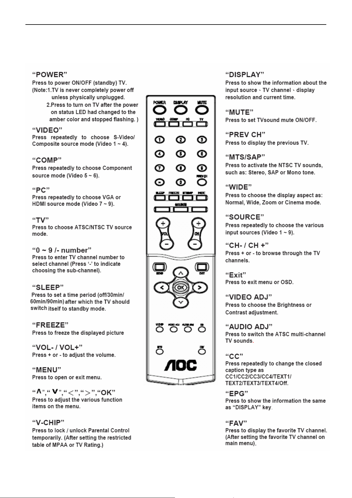
2.1. The Use Of Remote Control…….………….…….......5
2.2. To Use The Menus...…………………….……….......6
2.3. How To Connect…….…………………….……….....13
2.4. Front Panel Control Knobs……………….……….....15
3. Input/Output Specification…………....................…....16
4. Mechanical Instructions…………………….................18
5. Repair Flow Chart ……………………….…….…….....23
6. PCB Layout ………………..………………....….......28
6.1.Main Board…………..………………….……….......28
6.2.Power Board……………..………….……….......30
SAFETY NOTICE
ANY PERSON ATTEMPTING TO SERVICE THIS CHASSIS MUST FAMILIARIZE HIMSELF WITH THE
6.3.IR Board………………………………………….......33
6.4.Connector Board……………………..……….......34
6.5.Key Board……………………………….……….......34
7. White-Balance, Luminance Adjustment...................35
8 Block Diagram.……...........................................37
9. Schematic……………...…….……..………………..38
9.1 Main Board…….………..….…………….….......38
9.2. Power Board…………….……….………….......54
9.3. IR Board…………….……….………….…….......55
9.4. Key Board…………….……….………….......56
9.5. Side Board…………….……….……….…….......57
9.6. Audio Board…………………………………………58
10. Exploded View..…......................................59
11. BOM List……………….…………………………….60
12.Different Part List……….................................. 88
Horizontal Frequency
CHASSIS AND BE AWARE OF THE NECESSARY SAFETY PRECAUTIONS TO BE USED WHEN SERVICING
ELECTRONIC EQUIPMENT CONTAINING HIGH VOLTAGES.
CAUTION: USE A SEPARATE ISOLATION TRANSFOMER FOR THIS UNIT WHEN SERVICING
1
Page 2

42″ LCD TV AOC L42W665
Important Safety Notice
Proper service and repair is important to the safe, reliable operation of all AOC Company Equipment. The service
procedures recommended by AOC and described in this service manual are effective methods of performing service
operations. Some of these service operations require the use of tools specially designed for the purpose. The
special tools should be used when and as recommended.
It is important to note that this manual contains various CAUTIONS and NOTICES which should be carefully read in
order to minimize the risk of personal injury to service personnel. The possibility exists that improper service
methods may damage the equipment. It is also important to understand that these CAUTIONS and NOTICES ARE
NOT EXHAUSTIVE. AOC could not possibly know, evaluate and advise the service trade of all conceivable ways in
which service might be done or of the possible hazardous consequences of each way. Consequently, AOC has not
undertaken any such broad evaluation. Accordingly, a servicer who uses a service procedure or tool which is not
recommended by AOC must first satisfy himself thoroughly that neither his safety nor the safe operation of the
equipment will be jeopardized by the service method selected.
Hereafter throughout this manual, AOC Company will be referred to as AOC.
WARNING
Use of substitute replacement parts, which do not have the same, specified safety characteristics might create
shock, fire, or other hazards.
Under no circumstances should the original design be modified or altered without written permission from AOC.
AOC assumes no liability, express or implied, arising out of any unauthorized modification of design.
Servicer assumes all liability.
FOR PRODUCTS CONTAINING LASER:
DANGER-Invisible laser radiations when open AVOID DIRECT EXPOSURE TO BEAM.
CAUTION-Use of controls or adjustments or performance of procedures other than those specified herein may
result in hazardous radiation exposure.
CAUTION -The use of optical instruments with this product will increase eye hazard.
TO ENSURE THE CONTINUED RELIABILITY OF THIS PRODUCT, USE ONLY ORIGINAL MANUFACTURER'S
REPLACEMENT PARTS, WHICH ARE LISTED WITH THEIR PART NUMBERS IN THE PARTS LIST SECTION OF
THIS SERVICE MANUAL.
Take care during handling the LCD module with backlight unit
-Must mount the module using mounting holes arranged in four corners.
-Do not press on the panel, edge of the frame strongly or electric shock as this will result in damage to the screen.
-Do not scratch or press on the panel with any sharp objects, such as pencil or pen as this may result in damage to
the panel.
-Protect the module from the ESD as it may damage the electronic circuit (C-MOS).
-Make certain that treatment person’s body is grounded through wristband.
-Do not leave the module in high temperature and in areas of high humidity for a long time.
-Avoid contact with water as it may a short circuit within the module.
-If the surface of panel becomes dirty, please wipe it off with a soft material. (Cleaning with a dirty or rough cloth may
damage the panel.)
2
Page 3
42″ LCD TV AOC L42W665
Revision List
Version Release Date Revision Instructions TPV Model
A00 July-10-07 Initial Release E427AZNS2WA2NN
A01 Aug-15-07 Add New BOM
E427AZNS2WA2NN/
E427AZNK2WA5NN
3
Page 4
42″ LCD TV AOC L42W665
1. General Specification
Items Specification
Panel Type T420XW01 V500 TW AUO
Driving system TFT-LCD AUO Panel
Aspect Ratio 16: 9
Resolutions 1366 x768
Active Area 930.25 (H) x 523.01(V)
LCD Panel
Panel Typical Brightness:
Panel Typical Contrast:
Input
TV Function
Video Inputs
HDMI INPUT: Suggested scan rates: 1080i, 720p, 480p, 480i
OSD language English. French. Spanish
Wall Mount VESA 400 x 200 mm
Pixel Pitch 0.681 mm (H) X 0.681 mm(V)
Display colors 16.7 million
500 cd/㎡
1500:1
Color Temperature Cool / Warm/normal
H-Frequency 31KHz to 60KHz
V-Frequency 50Hz to 75 Hz
TV Standard NTSC/M
Color systems NTSC
AV RCA x 1 Audio L/R x 1
S-Video Y ,C x 1 Audio L/R x 1
COMPONENT Y, Pr/Cr, Pb/Cb x 1 Audio channel L / Rx 1
AUDIO Headphone Mini-jack for stereo (3.5ø)
Weight 24.5 kg
Dimensions
(Include Stand)
Power
Environment
Supplied Accessories:
NOTE: This TV set does not provide HD video Output.
1pcs Power cord, 1pcs Remote control(with two AA alkaline batteries), 1pcs User
Power Supply AC100V~240V, 50/60Hz
Power Consumption ≤250W
Operating Temperature + 0 °C ~ + 40 °C
Storage Temperature -10 °C ~ + 50 °C
Operating 10% ~ 85%
1050 mm(W) x 767 mm(H) x 290mm(L)
manual, 1pcs Signal cable, 1pcs Pc Audio cable
4
Page 5
42″ LCD TV AOC L42W665
2. Operating Instructions
2.1. The Use of Remote Control
5
Page 6
42″ LCD TV AOC L42W665
SETU
U
2.2 To Use the Menus
1. Press the MENU button to display the main menu
2. Use the cursor up/down to select a menu item.
3. Use the cursor left/right to enter a submenu.
4. Press the OK button to enable/disable the function.
5. Press the MENU or EXIT button to exit the menu. Press the MENU button to enter the main OSD (On Screen
Display). Adjust the items including Setup menu, Video menu, Audio menu and Feature menu. However, some
function items in the menus may only be enabled in the particular source modes.
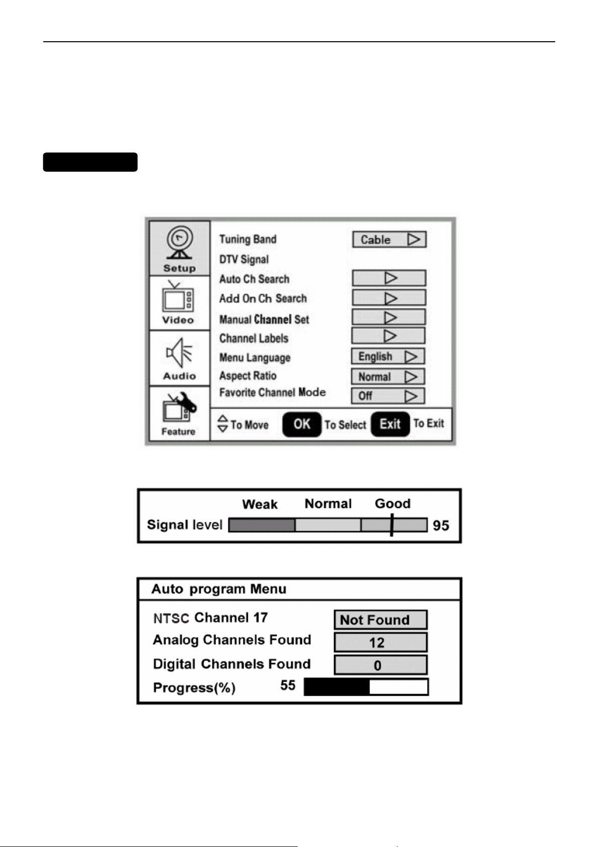
The Setup menu in TV mode shows as below. In others source modes, the Setup menu only shows Menu
Language and Aspect Ratio items.
P MEN
1. Tuning Band: Select TV source signal from the Air (antenna) or Cable (CATV).
2. DTV Signal: Show the intensity of the received DTV signal.
3. Auto Ch Search: Automatically scan all NTSC / ATSC TV channels and then store in the channel table. In
channel scan process, the OSD can display the number of channels which had been found.
4. Add on Ch search: Add channels which are new found.
5. Manual Channel Set: Show the channel setup table. User can choose to display the ATSC or NTSC TV channels
and then edit (add/delete) the channel numbers.
6.Channel Labels: Show the NTSC or ATSC TV channel label menu for user modifying channel labels specifically.
7. Menu Language: Select the menu display language. (English /Spanish /French)
8. Aspect Ratio: Select the display aspect ratio. (Normal / Zoom / Wide / Cinema)
9. Favorite Channel Mode: when favorite channel mode on user can edit favorite channel table in favorite channel
set option.
6
Page 7
42″ LCD TV AOC L42W665
V
U
U
IDEO MEN
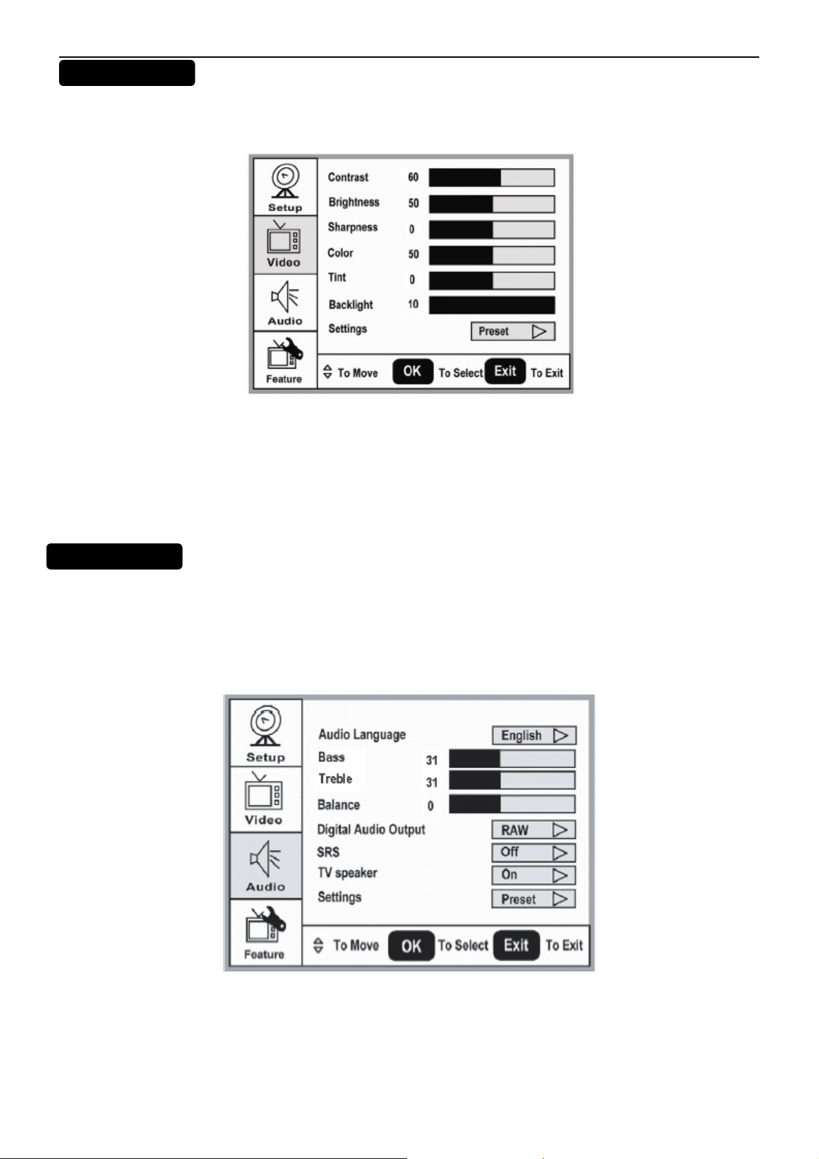
The Video menu in most source modes shows as below. It provides several video adjustment items for user fine
tuning the video display. Only in VGA source modes, the Video menu simply provides Contrast, Brightness, Back
light and Settings (Preset) items.
1. Contrast: Video contrast adjustment, the tuning range is 0 ~ 100.
2. Brightness: Video brightness adjustment, the tuning range is 0 ~ 100.
3. Sharpness: Video sharpness adjustment, the tuning range is -50 ~ 50.
4. Color: Video color chroma adjustment, the tuning range is 0 ~ 100.
5. Tint: Video tint adjustment, the tuning range is R50 ~ G50.
7. Settings: Restore the default video settings.
English
AUDIO MEN
The Audio menu in TV mode shows as below. It provides audio adjustment for user to modify the audio setting.
Except in ATSC TV mode, some audio adjustment items for user to modify the audio setting. Excepting in ATSC TV
mode, the Audio Language option is disable in others source modes. The audio language setting is only available
in ATSC TV source. Furthermore, the Bass and Treble tuning items are only enabled while the SRS option set “Off”
(tune-off the SRS sound effect). The Default states of Bass and Treble items are enabled as well as SRS option set
“Off”.
1. Audio Language: Change the audio language setting on ATSC TV programs. The number of the supported
audio languages depends on the ATSC TV programs.
2. Bass: Bass tone adjustment, the tuning range is 0 ~ 63. (The default state is enabled)
3. Treble: Treble tone adjustment, the tuning range is 0 ~ 63. (The default state is enabled)
4. Balance: Audio balance adjustment, the tuning range is L31 ~ R31.
5. Digital Audio Output: Digital audio output format selection, user can choose RAW (default) or PCM format.
6. SRS: Choose to turn on / off the SRS sound effect. The default value is Off.
7
Page 8
42″ LCD TV AOC L42W665
U
7. TV Speaker: Choose to turn on / off the TV internal speaker. The digital audio output signals、earphone output
signals and the composite L/R audio output signals will not be turn-off even though the TV speaker is off. The default
setting is On.
8. Settings: Restore the default audio settings.
FEATURE MEN
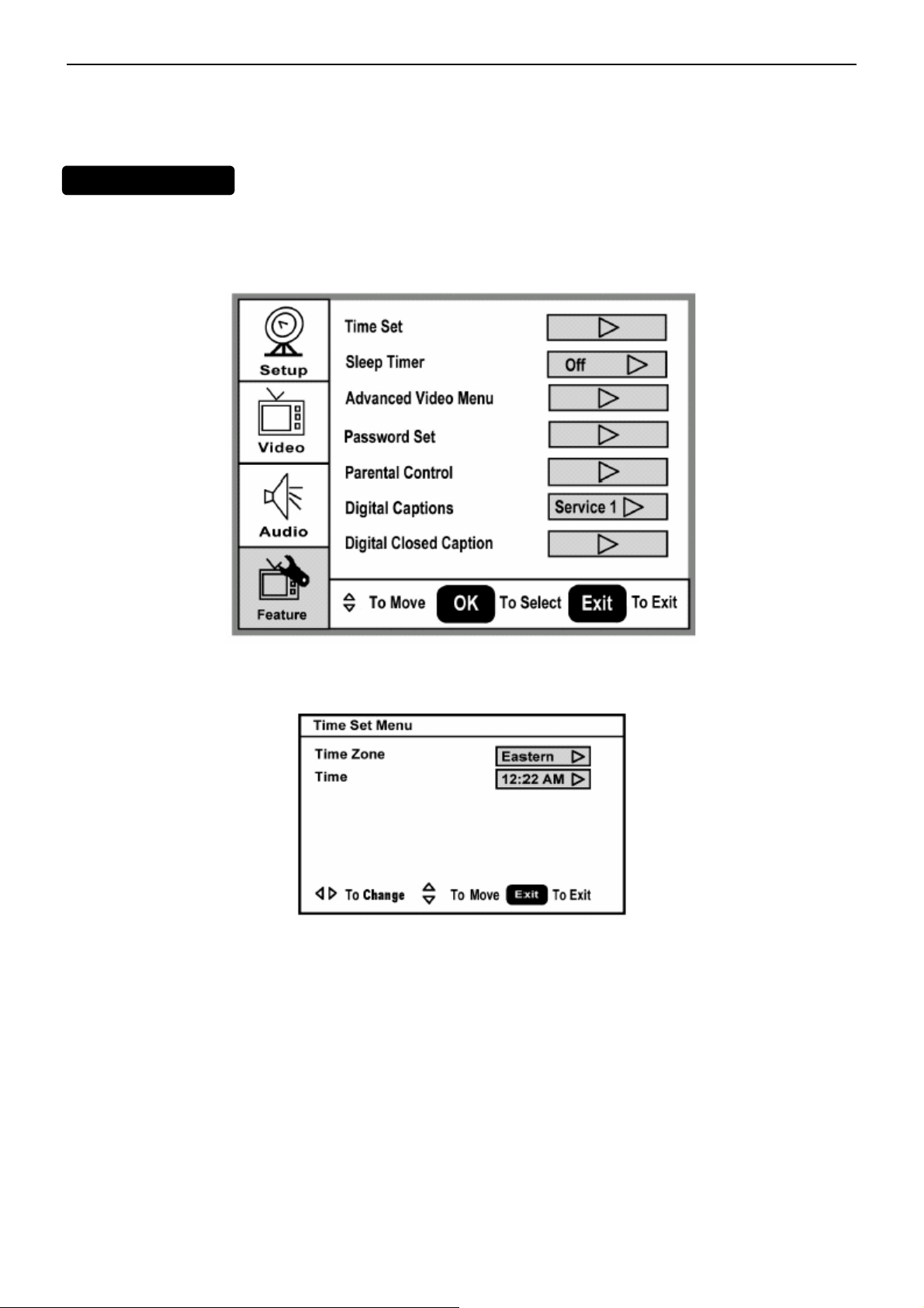
The Feature menu in TV mode shows as below. It provides certain optional control functions such as time set, sleep
timer, video noise reduction, parental control (V-chip) and close caption style setting. This menu gives users the
most flexibilities to satisfy their generally demands. According to the various requirements in different source modes,
certain features should be hidden (disable) on the menu. The details footnotes will be described clearly below.
1. Time Set: Set current time. This sub-menu includes Time Zone and Time items. 【Time Zone】item provides user
to set current time zone, such as: Pacific、Alaska、Hawaii、Eastern、Central and Mountain. 【Time】item provides
user to set the time clock.
2. Sleep Timer: Enable or disable the TV standby timer. User can set the TV standby timer as off / 5 min / 10 min /
15 min / 30 min / 45 min / 60 min / 90 min /120 min / 180 min / 240 min. Timer starts to count down after cursor
leaving the sub-menu. (At the moment, the item shows 『** min Left』and the cursor highlights on the Feature icon.)
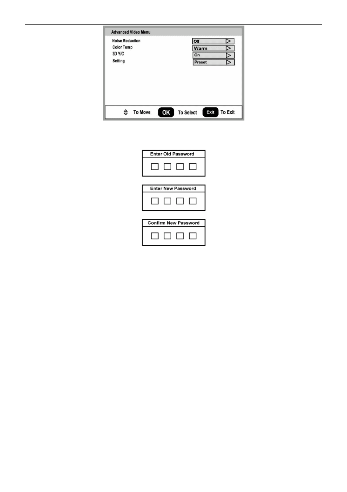
3. Advanced Video Menu: Provide the Noise Reduction setting 、Color Temperature and 3D Y/C filter options
for enhancing video quality.
【Noise Reduction】gives four NR effect degrees, such as: Low、Mid、High and Off. The default setting is off.
【3D Y/C】provides On / Off switches. The default setting is On.
【Color Temp】gives three color temperature modes as: Normal、Warm and Cool. The default mode is Warm.
【Setting】restores the default advanced video option settings.
8
Page 9
42″ LCD TV AOC L42W665
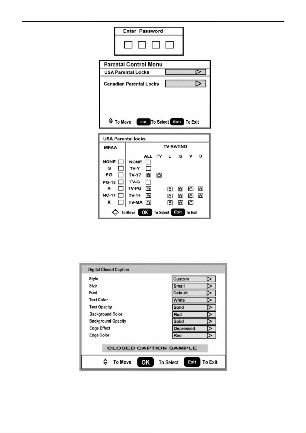
4. Password Set: Change the 4-numeral parental control password. Three steps are required for changing the
password: Enter Old Password -> Enter New Password -> Confirm New Password. Note: This item is only available
in TV, Composite and S-Video source modes. The default password is 『0 0 0 0』.
5. Parental Control: provide the parental Control (V-chip) function setting. Before entering the Parental Control
sub-menu, user has to key in the password first. Then enter the Parental Lock item, User can modify the restricted
table about MPAA or TV Rating respectively. While exiting the sub-menu, the parental control function is working.
The inhibitive channels or source signals can be un-lock through pressing the V-CHIP key on the remote control and
then key in the correct password. Note: This feature is only available in TV, Composite and S-Video source modes.
(The default password is: 0 0 0 0.)
9
Page 10
42″ LCD TV AOC L42W665
6. Digital Captions: Select the close caption options ( Service 1-6, Text 1-4 and CC 1-4) in digital TV mode. When
select service 1 to service 6 you can modulate parameters in the Digital Close Caption.
7. Digital Closed Caption: Provide numerous options for setting the close caption style. In the sub-menu. 【Style】
item can be set as Automatic or Custom mode. If Custom mode is selected, user can modify the detail styles
described below. The setting result will be shown immediately on the bottom side of the sub-menu OSD. Note: This
feature is only available in Digital TV (ATSC) mode.
【Size】: Digital close caption font size, which can be set as Small、Normal or Large.
【Font】: Digital close caption font style, which can be chosen as Default or Font 1 ~ 7.
【Text Color】: Giving Red / Green / Blue / Yellow / Magenta / Cyan / Black / White Colors.
【Text Opacity】: Giving Transparent / Translucent / Solid / Flashing modes.
【Background Color】: Giving Red / Green / Blue / Yellow / Magenta / Cyan / Black / White Colors.
【Background Opacity】: Giving Transparent / Translucent / Solid / Flashing modes.
10
Page 11
42″ LCD TV AOC L42W665
【Edge Effect】: The text edge effects, which gives None / Raised / Depressed / Uniform / Left Shadow / Right Shadow modes.
【Edge Color】: The colors of text edge effects, which provides Red / Green / Blue / Yellow / Magenta / Cyan / Black / White
Colors.
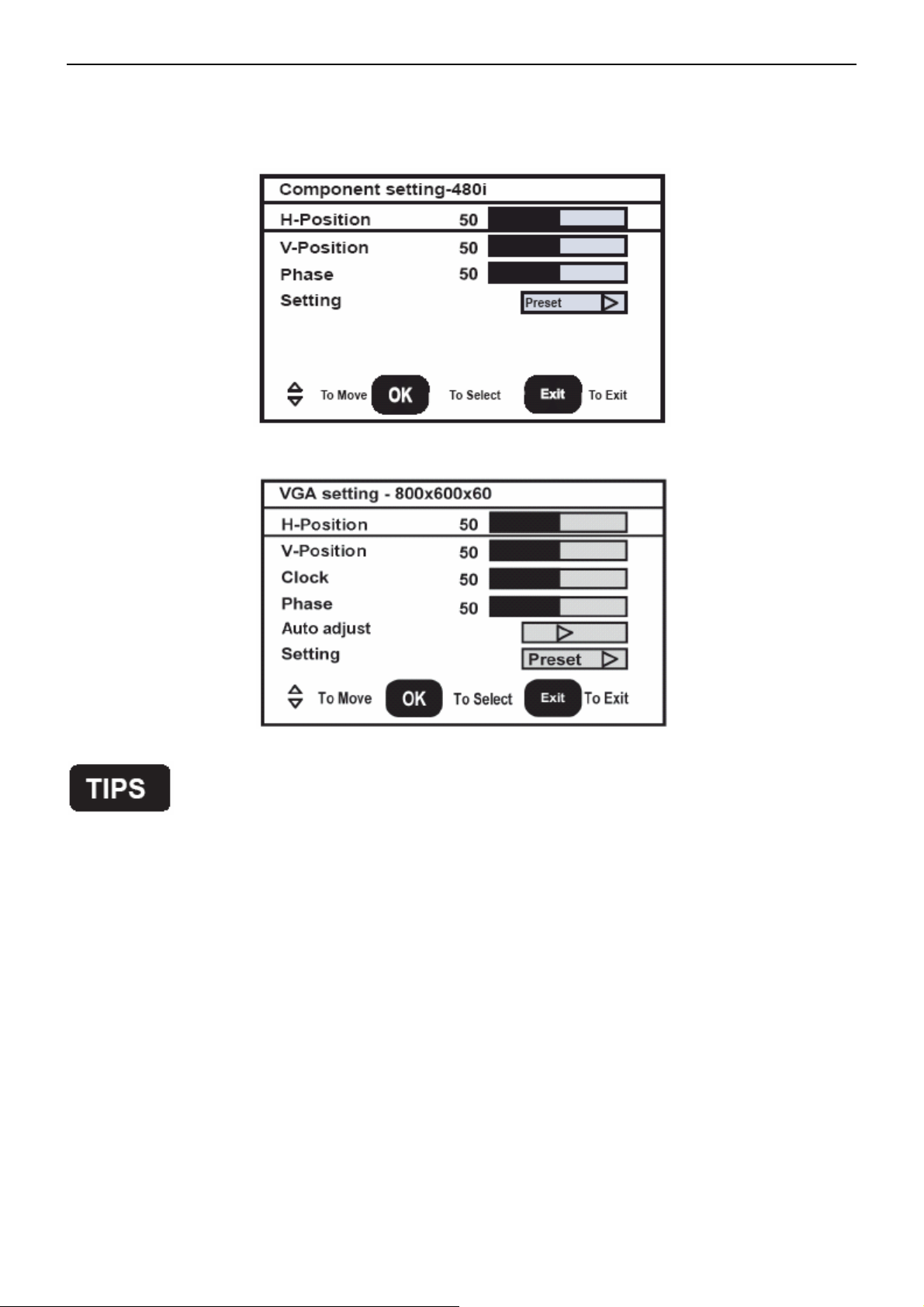
8. Component Set: This option only shows and is available in component mode,
such as: 【H-Position】、【V-Position】and【Phase】. All these items are giving the tuning range from 0 to 100.【Setting】item
provides the default component setting values restoring.
which provides fine tuning component display,
9. VGA Set: This option only shows and is available in VGA mode, which provides fine tuning VGA display, such as :
【H-Position】、【V-Position】、【Clock】and【Phase】. All these items are giving the tuning range from 0 to 100.【Setting】
item provides the default VGA setting values restoring.
Care of the screen
Do not rub or strike the screen with anything hard as this may scratch, mar, or damage the screen permanently.
Unplug the power cord before cleaning the screen. Dust the TV by wiping the screen and the cabinet with a soft,
clean cloth. If the screen requires additional cleaning, use a clean, damp cloth. Do not use liquid cleaners or aerosol
cleaners.
Mobile telephone warning
To avoid disturbances in picture and sound, malfunctioning of your TV or even damage to the TV, keep away your
mobile telephone from the TV.
End of life directives
We are paying a lot of attention to produce environmentally friendly in green focal areas. Your new receiver contains
materials, which can be recycled and reused. At the end of its life specialized companies can dismantle the
discarded receiver to concentrate the reusable materials and to minimize the amount of materials to
be disposed of. Please ensure you dispose of your old receiver according to local regulations.
Regulatory Notices – Federal Communications Commission Notice
This equipment has been tested and found to comply with the limits for a Class B digital device, pursuant to part 15
of the FCC Rules. These limits are designed to provide reasonable protection against harmful interference in a
residential installation. This equipment generates, uses, and can radiate radio frequency energy and, if not installed
and used in accordance with the instructions, may cause harmful interference to radio communications. However,
there is no guarantee that interference will not occur in a particular installation. If this equipment does cause harmful
interference to radio or television reception, which can be determined by turning the equipment off and on, the user
is encouraged to try to correct the interference by one or more of the following measures:
1.Reorient or relocate the receiving antenna.
11
Page 12

42″ LCD TV AOC L42W665
2.Increase the separation between the equipment and the TV.
3.Connect the equipment into wall power outlet on a circuit different from that to which the receiver is connected.
4.Consult the dealer or an experienced radio or television technician for help.
Modifications –
The FCC requires the user to be notified that any changes or modifications made to this device that are not
expressly approved by Norcent Technology Inc. may void the user’s authority to operate the equipment.
Cables –
Connections to this device must be made with shielded cables with metallic RF/EMI connector hoods to maintain
compliance with FCC Rules and Regulations.
Canadian notice –
This Class B digital apparatus meets all requirements of the Canadian Interference-Causing Equipment
Regulations.
12
Page 13
42″ LCD TV AOC L42W665
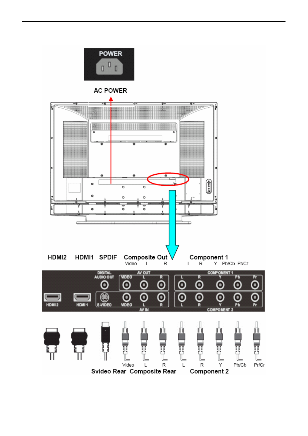
2.3 How to Connect
There are several ways to connect your TV. Please use the following chart to determine which connection is best
for you.
Once your equipment is connected, use the following procedure to view the input signal:
Press the source button on the remote controller to select the relevant source to view. (ex: Press VIDEO button to
select “Video1 Composite Rear” if you have connected a DVD player to Video1 Composite socket.) "HDMI, the
HDMI logo and High-Definition Multimedia Interface are trademarks or registered trademarks of HDMI Licensing
LLC."
13
Page 14

42″ LCD TV AOC L42W665
Note: The MUTE key on the remote control works on both TV internal speaker and the earphone output.
14
Page 15
42’’ LCD TV AOC L42W665
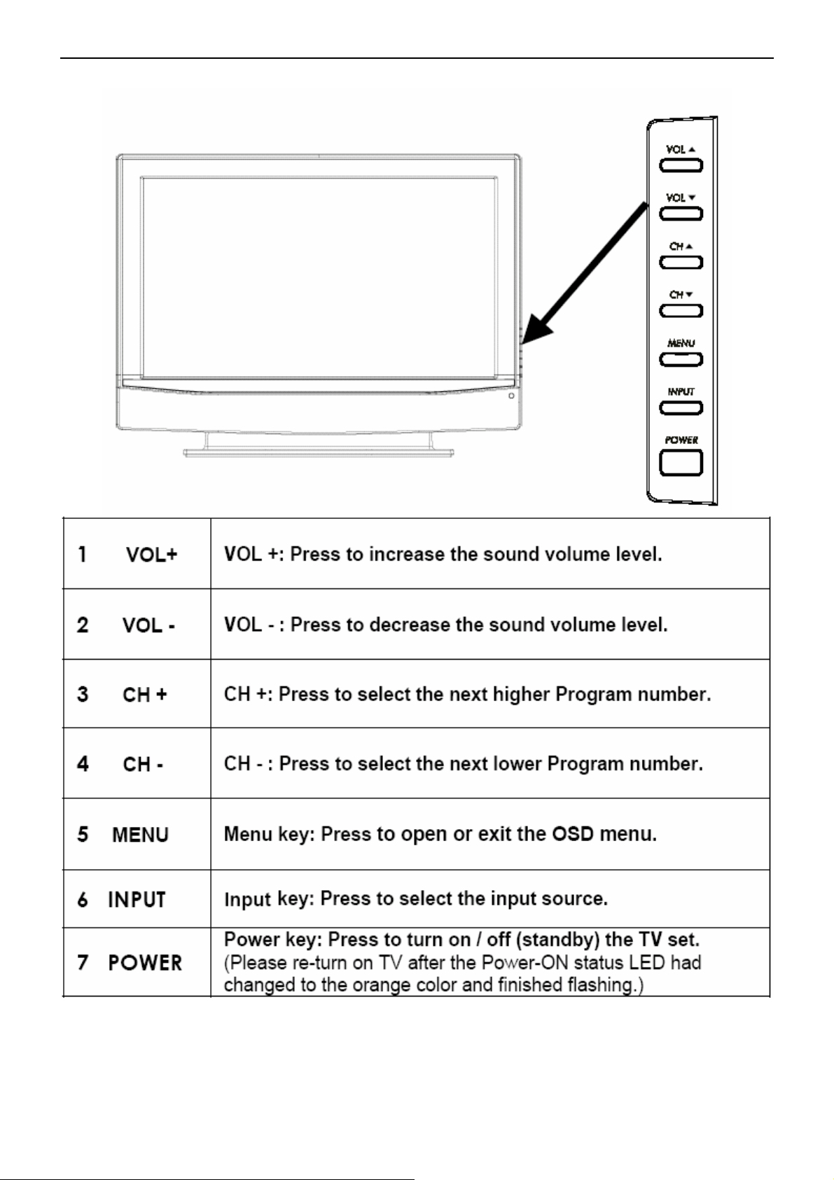
2.4 Front Panel Control Knobs
15
Page 16
42’’ LCD TV AOC L42W665
3. Input/Output Specification
3.1 RGB Signal input
15 - Pin Color Display Signal Cable
Pin No. Description Pin No. Description
1 Red Video 9 Mandatory +5V Supply for PC Bypass
2 Green Video 10 Sync Ground
3 Blue Video 11 SDA(Remote Control)
4 SCL(Remote Control) 12 Bi-directional Data (SDA) for PC Bypass
1
6
11 15
5
10
5 Ground 13 H-Sync.
6 Red Video Ground 14 V-Sync.
7 Green Video Ground 15 Data Clock (SCL) for PC Bypass
8 Blue Video Ground
3.2 AV/S-Video/Component signal input
AV (Composite Video input)
Video1 / Video2
Amplitude 1.0 V(p-p), negative sync.
Impedance 75 ohm terminated
S-Video (Y / C input)
S-Video1 / S-Video2
System NTSC
Y signal amplitude 1.0Vpp (including sync)
C signal amplitude 0.286Vpp
Impedance 75 ohm terminated
System NTSC
Component (Y, Pb/Cb, Pr/Cr input)
Component1/Component2
System 1080i, 480p, 720p, 480i
Y signal amplitude 1.0Vpp (including sync)
Cr, (R-Y) / Cb, (B-Y)
Signal amplitude
±0.35Vpp, 75 ohm
Impedance 75 ohm terminated
Y = 0.299R + 0.587G + 0.114B
(R-Y)= 0.701R + 0.587G + 0.114B
(B-Y)=0.299R + 0.587G + 0.886B
16
Page 17
42’’ LCD TV AOC L42W665
3.3 Compatible Mode Table
VESA MODES
Horizontal Vertical
Nominal
Pixel
Clock
(MHz)
Mode Resolution Total
640x480@60Hz 800 x 525 31.469 N 59.940 N 25.175
Nominal
Frequency
(KHz)
Sync
Polarity
Nominal
Freq.
(Hz)
Sync
Polarit
y
VGA
SVGA
XGA
WXGA 1360x768@60Hz 1792x795 47.712 P 60.015 P 85.5
640x480@72Hz 832 x 520 37.861 N 72.809 N 31.500
640x480@75Hz 840 x 500 37.5 N 75 N 31.500
800x600@56Hz 1024 x 625 35.156 P 56.25 P 36.000
800x600@60Hz 1056 x 628 37.879 P 60.317 P 40.000
800x600@72Hz 1040 x 666 48.097 P 72.188 P 40.000
800x600@75Hz 1056 x 625 46.0875 P 75 P 49.5
1024x768@60Hz 1344x806 48.363 N 60.004 N 65.000
1024x768@70Hz 1328x806 56.476 N 70.069 N 75.000
1024x768@75Hz 1312x800 60.023 P 75.029 P 78.750
17
Page 18
42″ LCD TV AOC L42W665
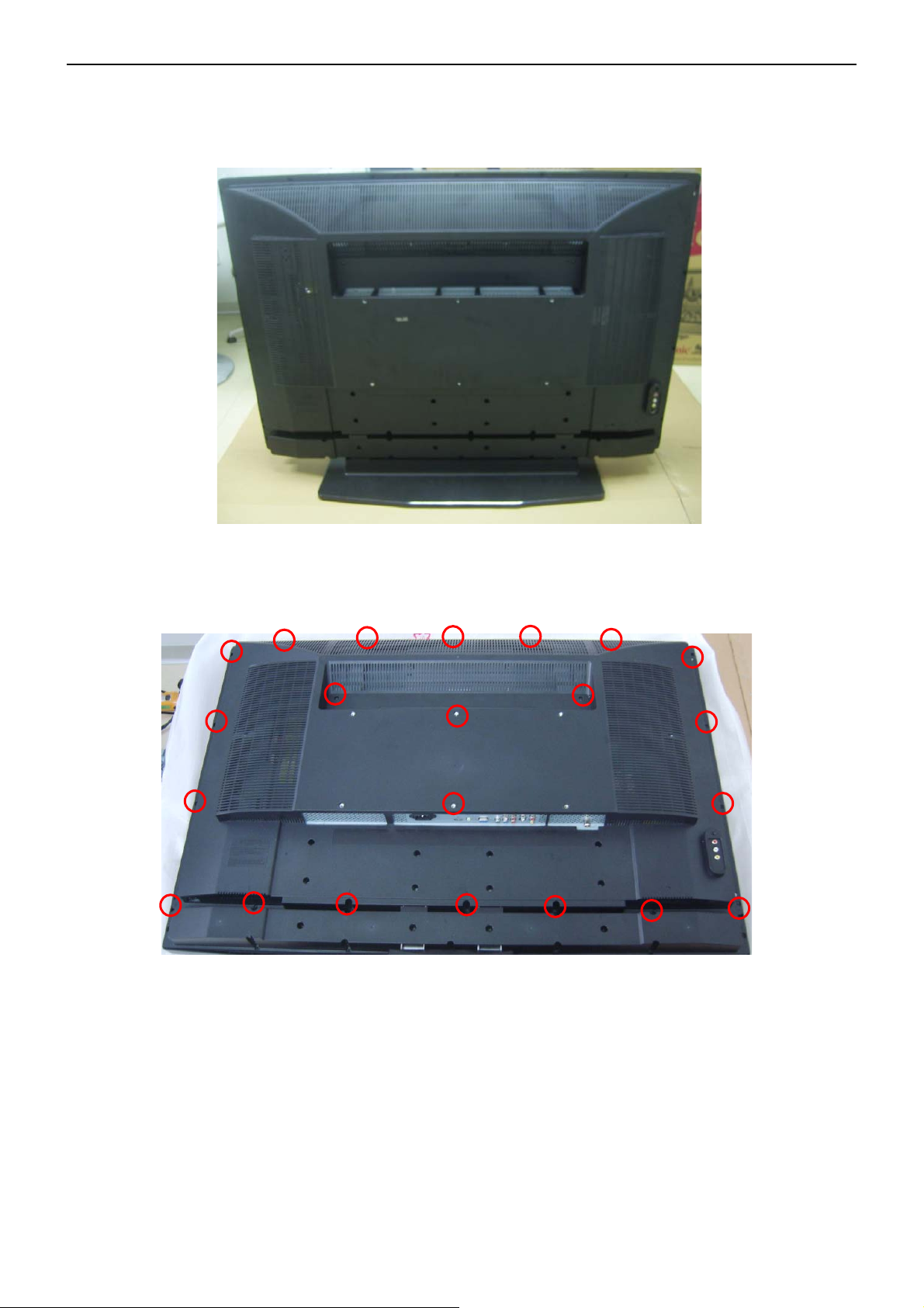
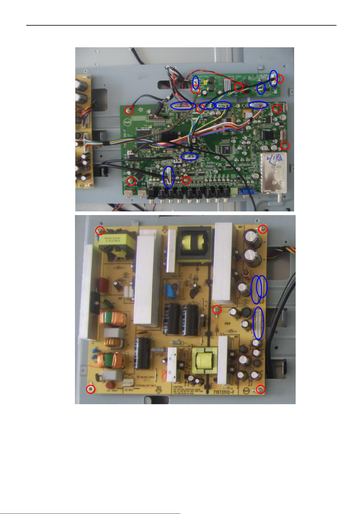
4. Mechanical Instructions
1. Remove the base first with six screws in the base.
2. Remove the screws in red to remove the rear cover.
18
Page 19
42″ LCD TV AOC L42W665
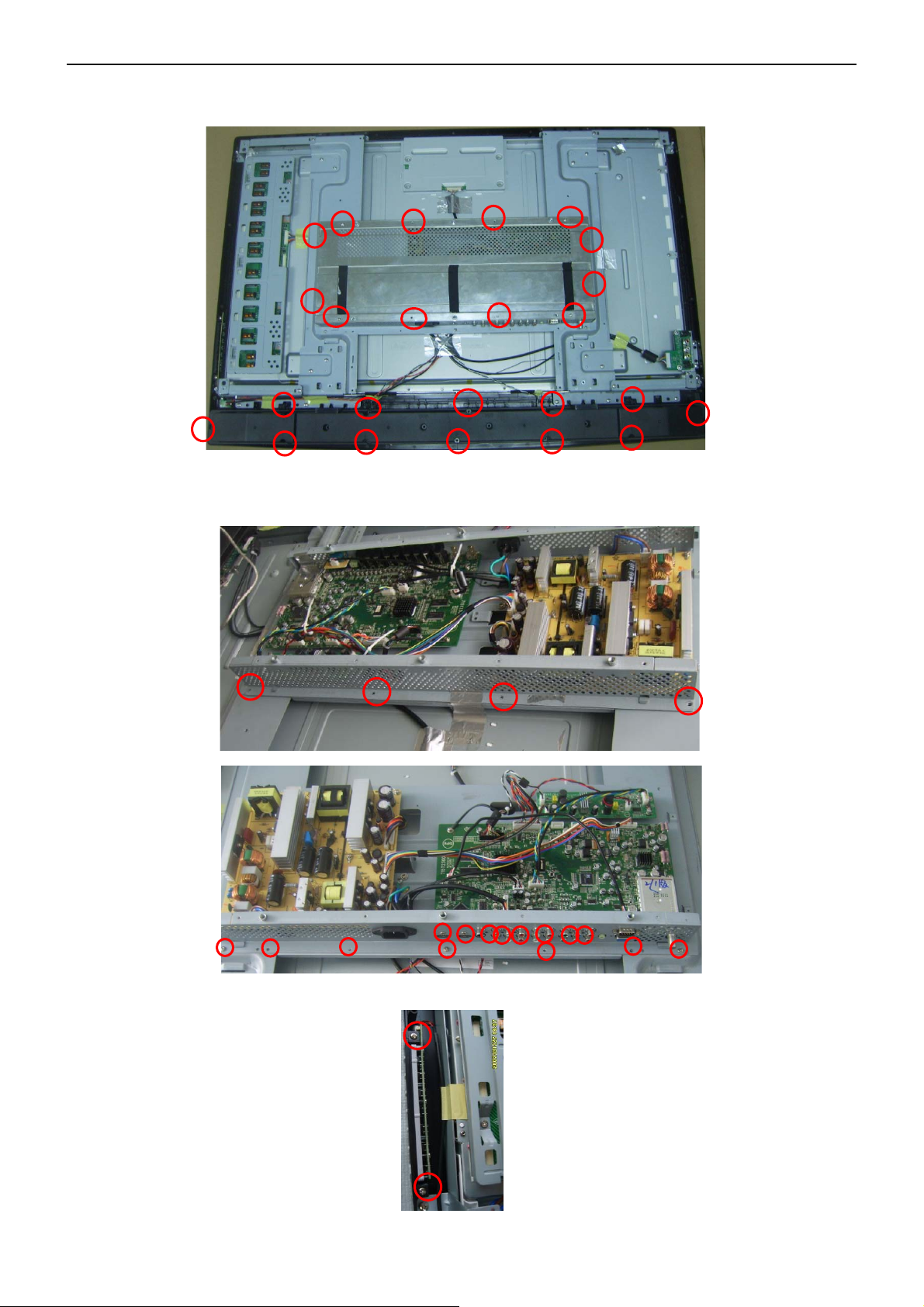
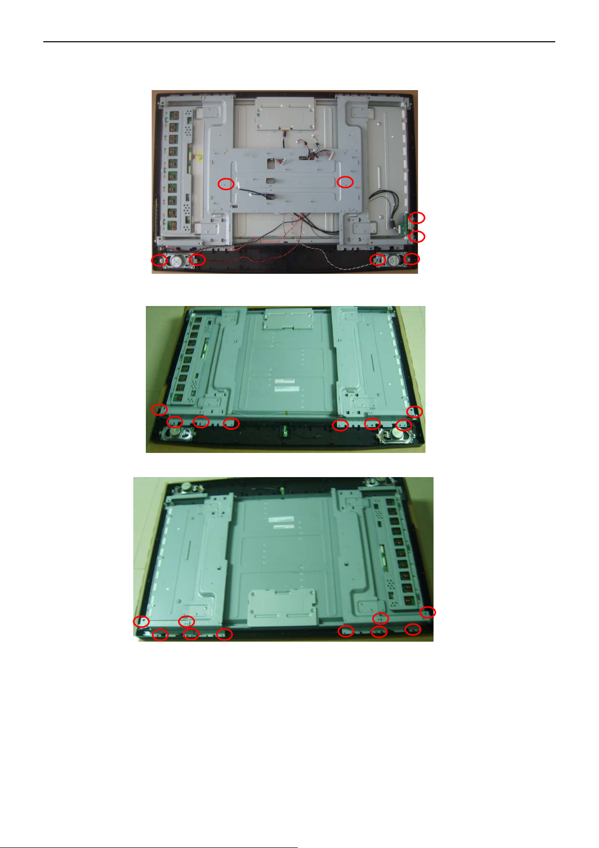
3. Remove the speaker cover and the cover-shield.
4. Remove the screws in red to remove the two metallic bracket and button assemble.
19
Page 20
42″ LCD TV AOC L42W665
5. Remove the screws and pull out the connecters to remove the board.
.
20
Page 21
42″ LCD TV AOC L42W665
6. Remove the screws and connectors in red to remove the bezel and speakers.
21
Page 22
42″ LCD TV AOC L42W665
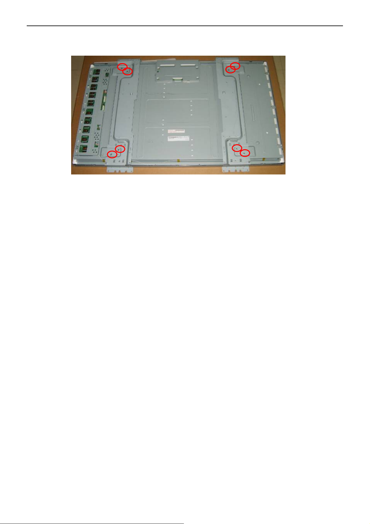
7. Remove the screws to remove the left and right metallic bracket.
22
Page 23
42″ LCD TV AOC L42W665
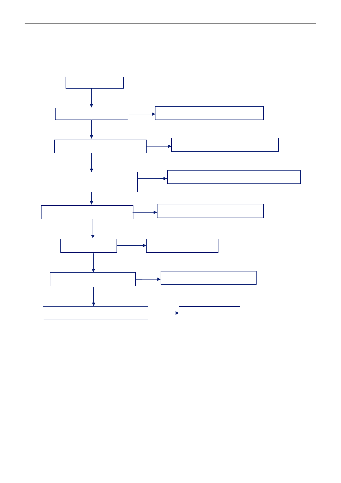
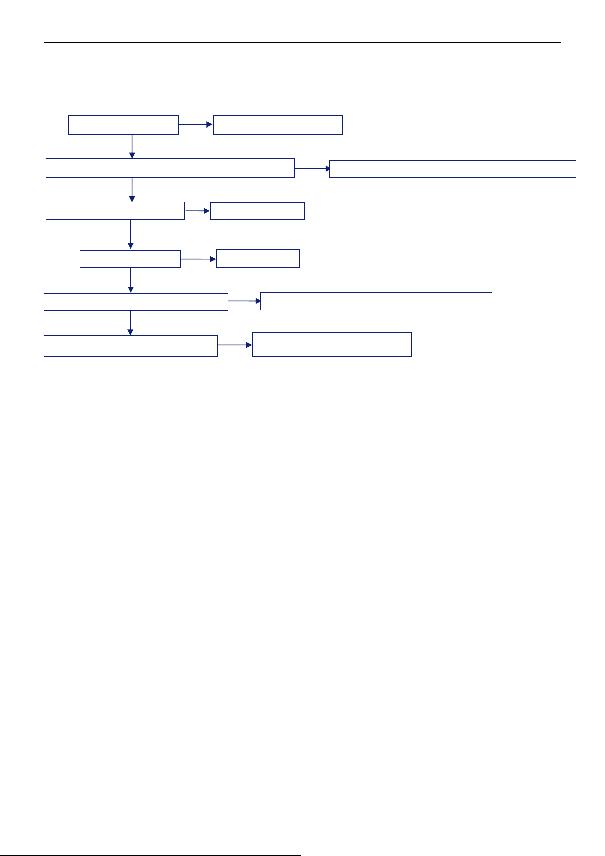
5. Repair Flow Chart
1. No Power (No LED indicator)
NO POWER
NG
Check power cord
Plug in power cord and interface
OK
Check F901, BD901, D902
OK
Check IC931, IC971,Q931 ,Q932
(VCC)
OK
Check IC901,Q903,Q904
OK
NG
Check T931
OK
Check D950, D951,ZD931
OK
Check L931,L932
NG
Replace F901 or BD901 or D902
NG
Replace IC931, IC971, or Q931 or Q932 (VCC)
NG
Replace IC901,Q903,Q904
Replace T931, T971
NG
Replace D950, D951,ZD931
NG
Check L931,L932
23
Page 24
42″ LCD TV AOC L42W665
ace U
903,U
906,U
907,U908,U
909,U
9
2
2
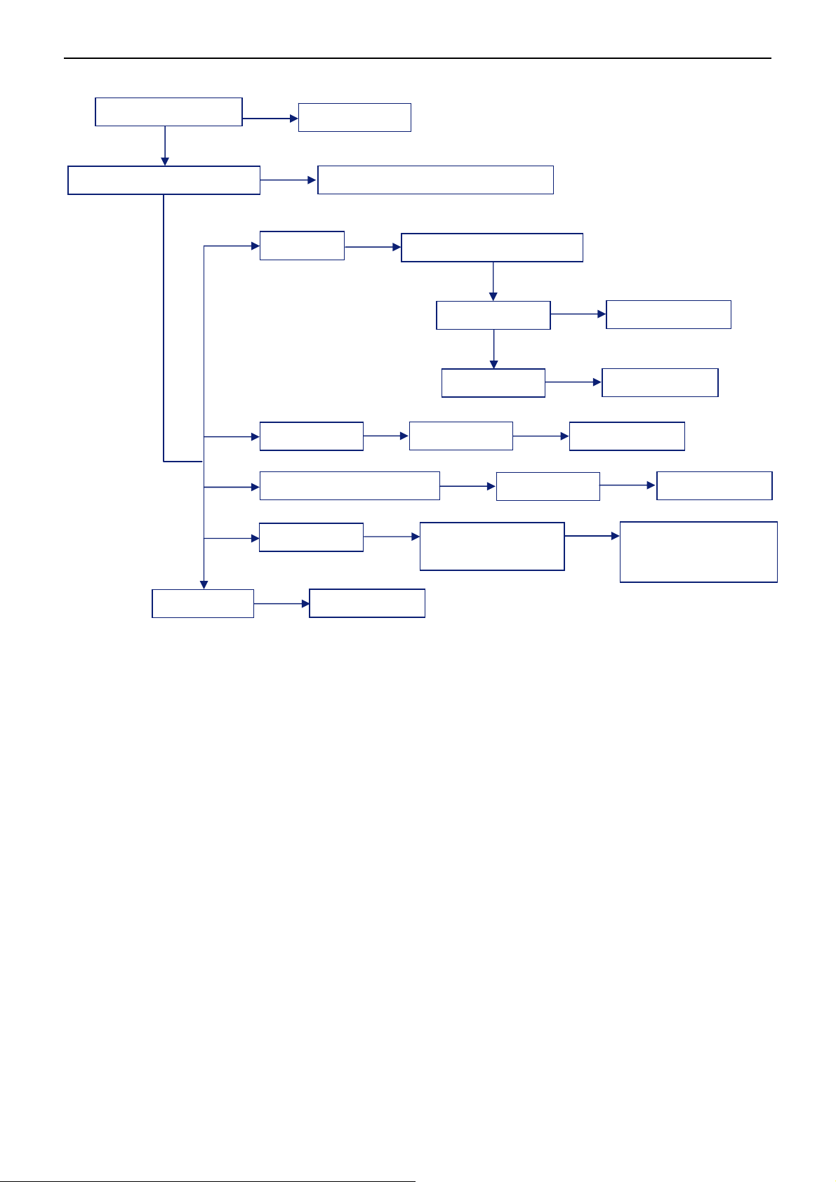
2. Can not start (LED indicator yellow)
Check key board
OK
Check the standby voltage of main board
OK
Check U401
OK
Check U404
OK
Check I
Check the POWER_ON SIGNAL
C communication
OK
NG
NG
NG
Replace U401
Repair the key board
NG
Replace U404
NG
Check the components of I
NG
Replace Q906,Q907,Q913
Repl
11
C communication
24
Page 25
42’’ LCD TV AOC L42W665
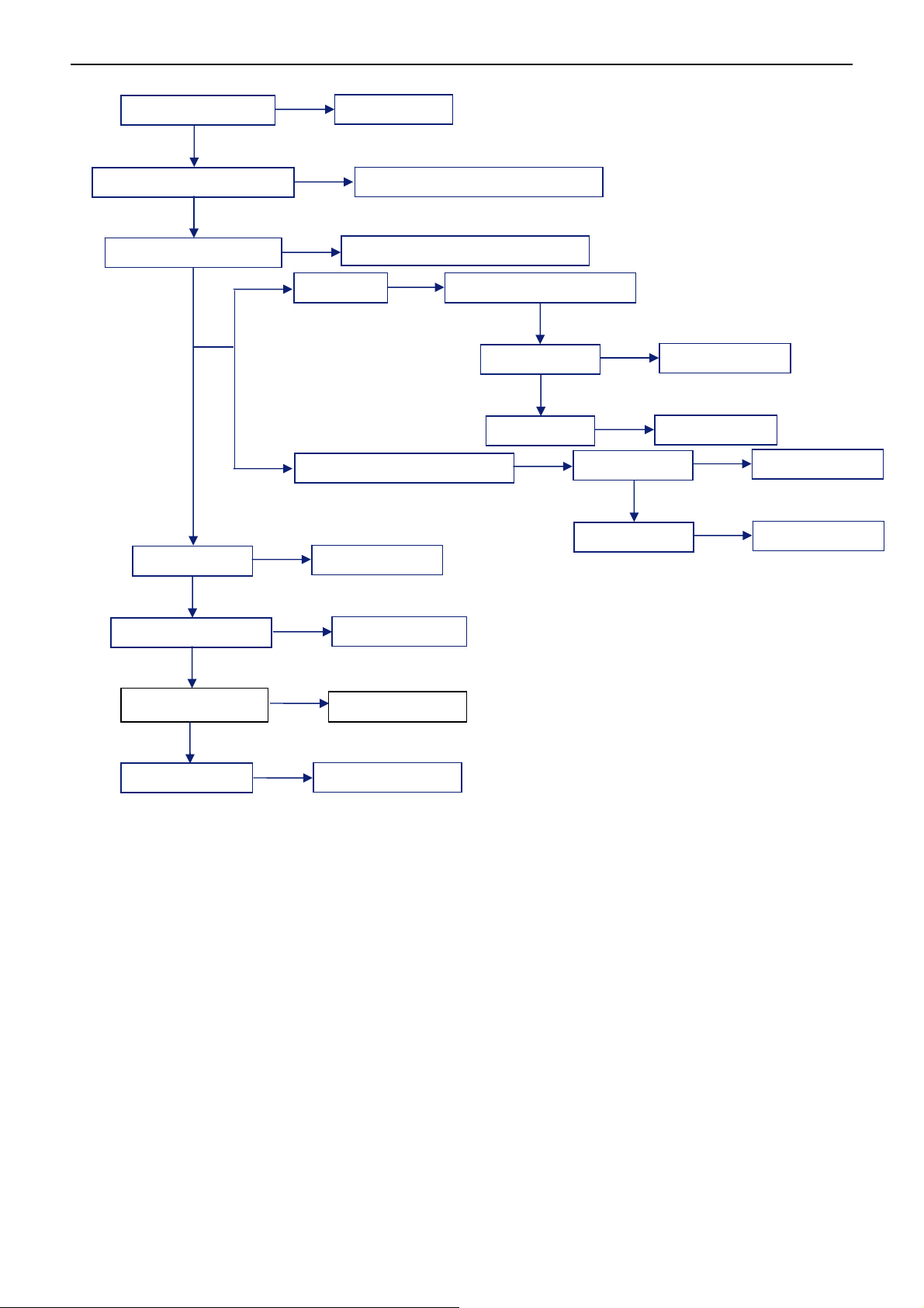
3. Abnormal display
Check the source
OK
NG
Reset source
Check signal filter circuit
OK
OK
NG
TV signal
NTSC, AV,
Component, PC signal
HDMI signal
Replace the filter or inductance
Check TV system setup
OK
Check TU701
OK
Check U701
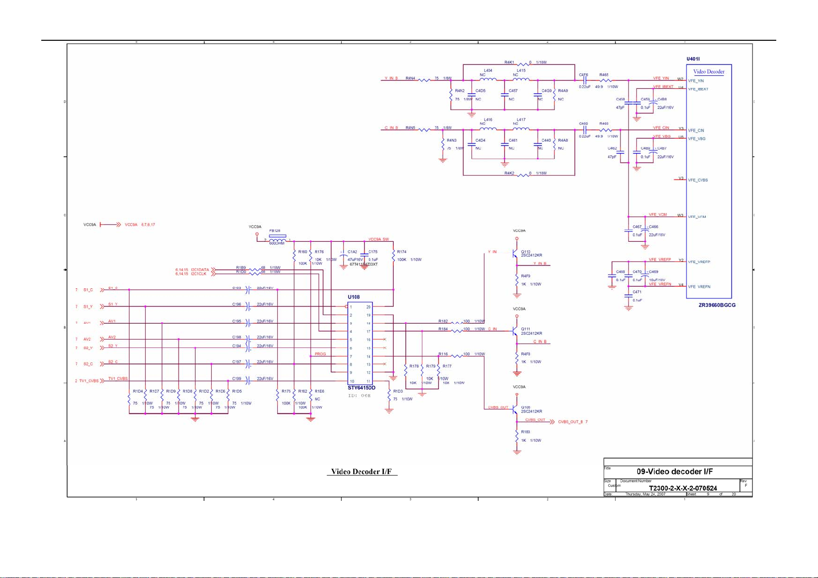
Check U108
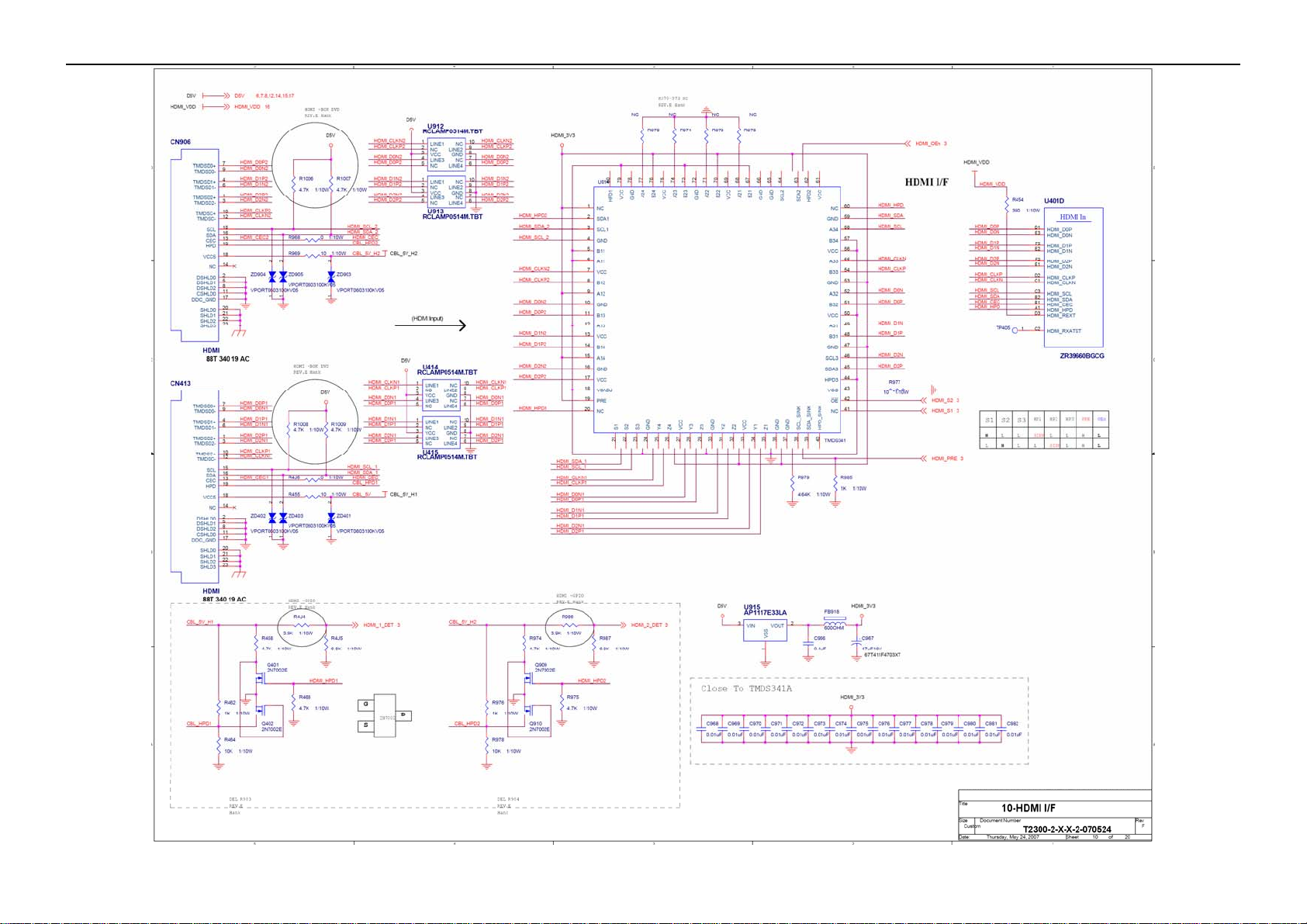
Check U414, U415,
U914
NG
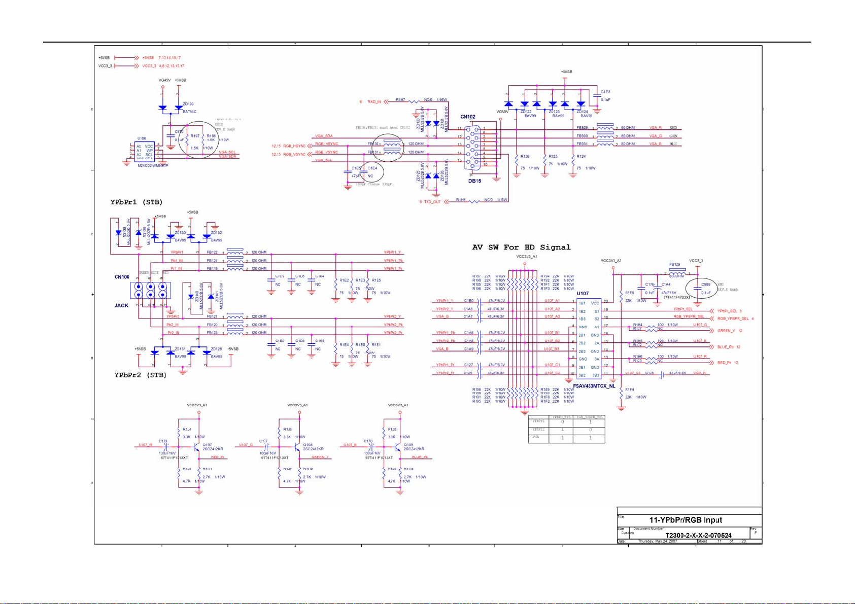
Check U107
NG
NG
Replace U701
Replace U108
NG
NG
Replace TU701
Replace U107
Replace U414, U415,
U914
Check U401
NG
Replace U401
25
Page 26
42’’ LCD TV AOC L42W665
p
A
4. No sound
Check the source
OK
NG
Reset source
Check signal filter circuit
Check Earphone jack
OK
Check U401
Check U600
NG
NG
SIF signal Check TV system setu
V, Co mponent, PC signal
NG
NG
Replace the filter or inductance
Replace the Earphone jack
OK
Check TU701
OK
Check U701
Replace U401
Replace U600
NG
NG
Check U103
OK
Check U101
Replace TU701
Replace U701
Replace U103
Replace U101
OK
Check U1, U2, U3
Check speaker
NG
NG
Check U1, U2, U3
Replace speaker
26
Page 27
42’’ LCD TV AOC L42W665
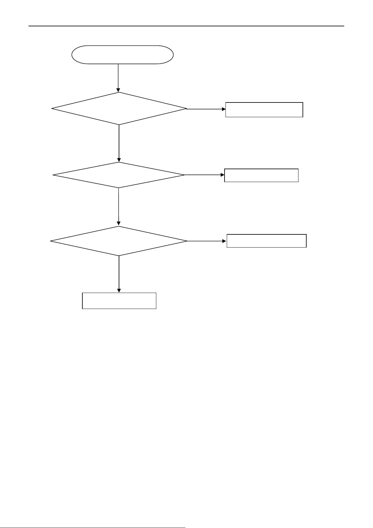
5. Key Board
OSD is unstable or not working
Is Key Pad Board connecting normally?
Y
Is Button Switch normally?
Y
Is Key Pad Board Normally?
Y
Check Main Board
N
Connect Key Pad Board
N
N
Replace Button Switch
Replace Key Pad Board
27
Page 28
42’’ LCD TV AOC L42W665
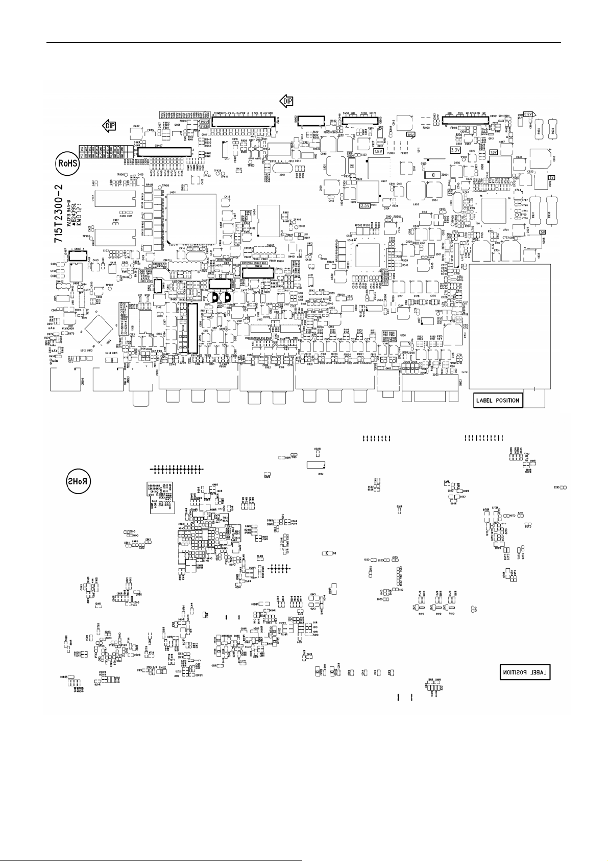
6. PCB Layout
6.1 Main Board
28
Page 29

42’’ LCD TV AOC L42W665
29
Page 30

42’’ LCD TV AOC L42W665
6.2 Power Board
30
Page 31

42’’ LCD TV AOC L42W665
31
Page 32

42’’ LCD TV AOC L42W665
32
Page 33
42’’ LCD TV AOC L42W665
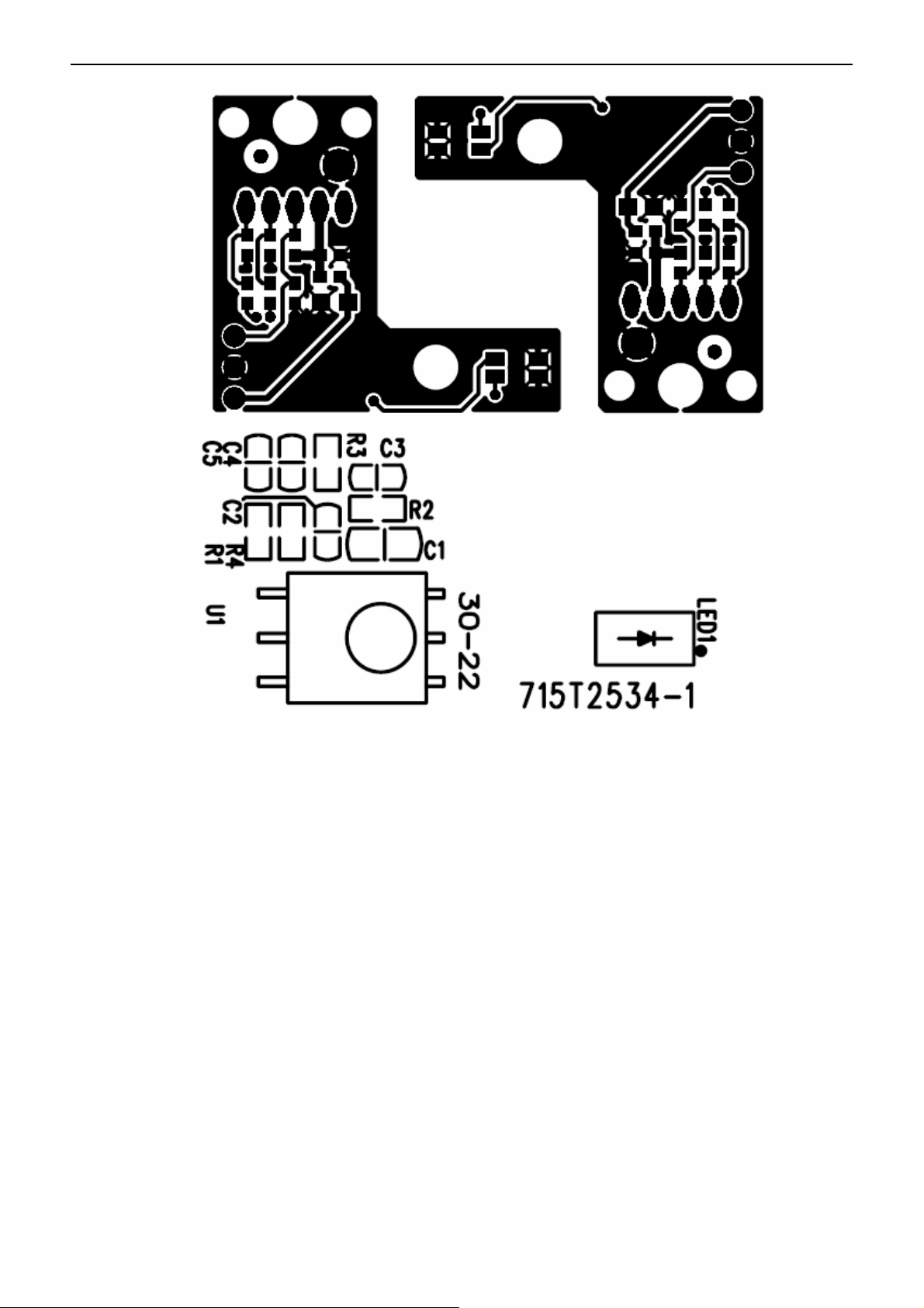
6.3 IR Board
33
Page 34

42’’ LCD TV AOC L42W665
6.4 Side Board
6.5 Key Board
34
Page 35

42’’ LCD TV AOC L42W665
7. White Balance, Luminance Adjustment
Approximately 30 minutes should be allowed for warm up before proceeding white balance adjustment.
Please select channel 03 to adjust the white balance.
Color Temp. Cold Normal Warm
x 289 299 313
PC MODE
AV MO D E
HDMI
COMPONENT
(1080i/720p
480i/480p)
Note: The tolerance of the color coordinates should be less than ± 20.
How to setting MEM. channel you can reference to Chroma-7120 user guide or simple use “ SC” key and “ NEXT”
key to modify x, y , Y value and use “ID” key to modify the TEXT description.
Following is the procedure to do white-balance adjust
Note: Step of AV, HDMI, COMPONENT1080i,720p 480i,480p mode adjustment is the same as PC mode
PC mode:
Ⅰ. In the TV mode adjust volume to zero and press number key 9 Æ 8 Æ 7 Æ 6. It will achieve the
factory mode. Select the item of White Balance and press right key to enter it.
In the White Balance you can adjust 8 items.
1-3 items is RO, GO, BO Æ R, G, B Bias adjust.
4-6 items is RG, GG, BG Æ R, G, B Gain adjust.
7 item needn’t adjust
8 items is color temperature select: Cool, Normal, and Warm.
Ⅱ. Bias (Low luminance) adjustment:
1. Set the raster pattern (Black pattern with 1024×768) Input.
2. Adjust the brightness on OSD until chroma 7120 measurement reach the lowest value.
Ⅲ. Gain adjustment:
A. Adjust Cold color-temperature:
1. Set the Contrast of OSD function to 80 and Adjust Brightness to chroma-7120 Y>450 cd/m
2. Switch the chroma-7120 to RGB-mode (with press “MODE” button)
3. Switch the MEM. channel to Channel 03 (with up or down arrow on chroma-7120)
4. The LCD-indicator on chroma-7120 will show x =289, y =304, Y>450 cd/m
5. Adjust the 4 item: RG, until chroma 7120 indicator reached the value R=100
6. Adjust the 5 item: GG, until chroma-7120 indicator reached the value G=100
7. Adjust the 6 item: BG, until chroma-7120 indicator reached the value B=100
8. Repeat above procedure until chroma-7120 RGB value meet the tolerance =100±2
9. Switch the chroma-7120 to x, y, Y mode with press “MODE” button to check the color temp is in SPEC. or not.
10. Enter the 8 item to select another color temperature to adjust.
y 304 315 329
Y 450 450 450
x 289 299 313
y 304 315 329
Y 450 450 450
x 289 299 313
y 304 315 329
Y 450 450 450
x 289 299 313
y 304 315 329
Y 450 450 450
2
± 30 cd/m2
2
± 30 cd/m2
35
Page 36

42’’ LCD TV AOC L42W665
B. Adjust Normal color-temperature:
1. Set the Contrast of OSD function to 80 and Adjust Brightness to chroma-7120 Y>450 cd/m2 ± 30 cd/m2
2. Switch the chroma-7120 to RGB-mode (with press “MODE” button)
3. Switch the MEM. channel to Channel 03 (with up or down arrow on chroma-7120)
4. The LCD-indicator on chroma-7120 will show x =299, y =315, Y>450 cd/m
5. Adjust the 4 item: RG, until chroma 7120 indicator reached the value R=100
6. Adjust the 5 item: GG, until chroma-7120 indicator reached the value G=100
7. Adjust the 6 item: BG, until chroma-7120 indicator reached the value B=100
8. Repeat above procedure until chroma-7120 RGB value meet the tolerance =100±2
9. Switch the chroma-7120 to x, y, Y mode with press “MODE” button to check the color temp is in SPEC. or not.
10. Enter the 8 item to select another color temperature to adjust.
C. Adjust Warm color-temperature:
1. Set the Contrast of OSD function to 80 and Adjust Brightness to chroma-7120 Y>450 cd/m
2. Switch the chroma-7120 to RGB-mode (with press “MODE” button)
3. Switch the MEM. channel to Channel 03 (with up or down arrow on chroma-7120)
4. The LCD-indicator on chroma-7120 will show x =313, y =324, Y>450 cd/m
5. Adjust the 4 item: RG, until chroma 7120 indicator reached the value R=100
6. Adjust the 5 item: GG, until chroma-7120 indicator reached the value G=100
7. Adjust the 6 item: BG, until chroma-7120 indicator reached the value B=100
8. Repeat above procedure until chroma-7120 RGB value meet the tolerance =100±2
9. Switch the chroma-7120 to x, y, Y mode With press “MODE” button to check the color temp is in SPEC. or not.
10. Enter the 8 item to select another color temperature to adjust.
2
± 30 cd/m2
2
± 30 cd/m2
2
± 30 cd/m2
Ⅳ.Switch different source:
Press the source key on the remote control to switch different source to adjust the AV, HDMI, CONPONENT 480i
and COMPONENT 480p mode.
Press “Exit” button on remote control to quit from factory mode.
36
Page 37

42’’ LCD TV AOC L42W665
8. Block Diagram
37
Page 38

42’’ LCD TV AOC L42W665
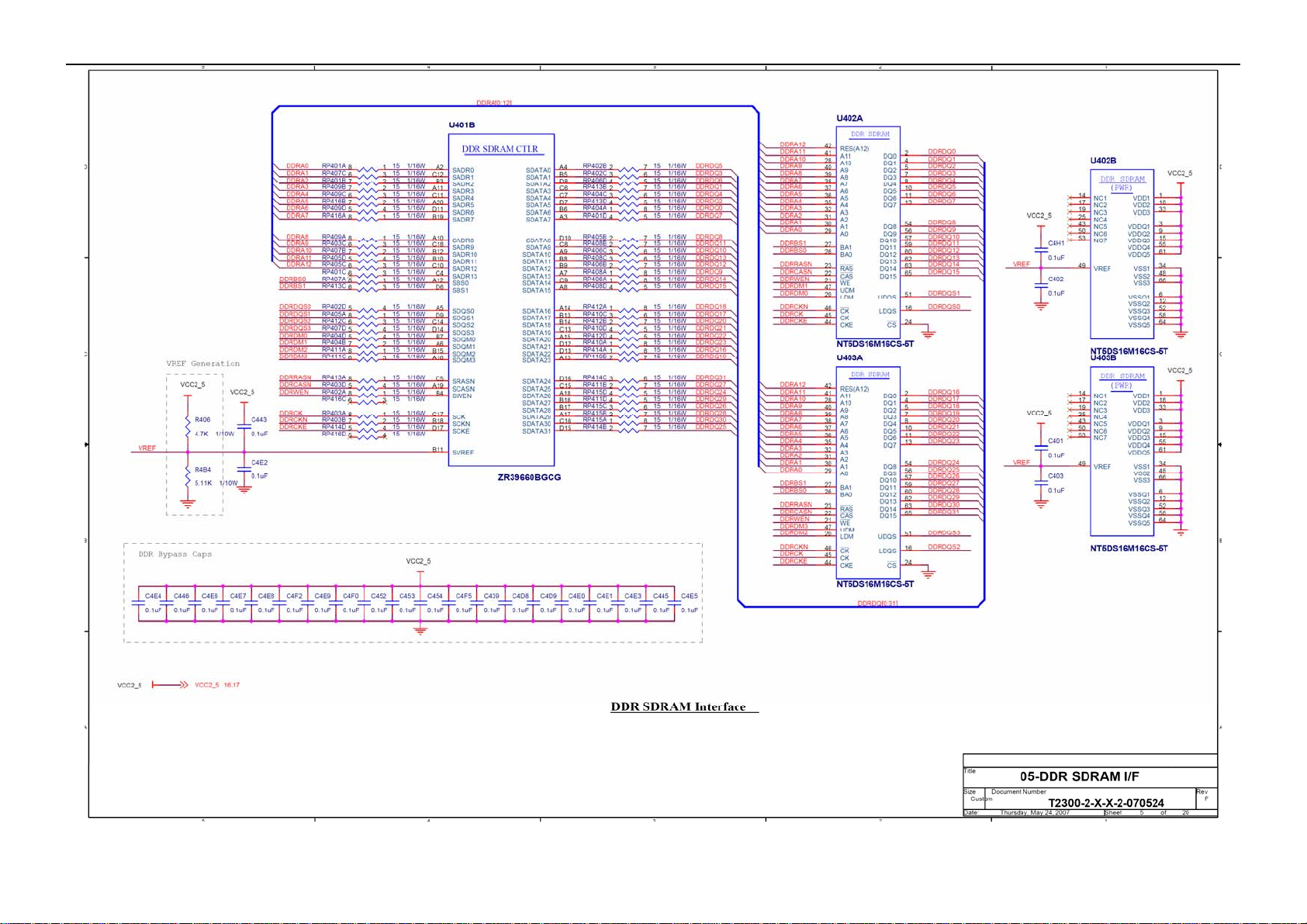
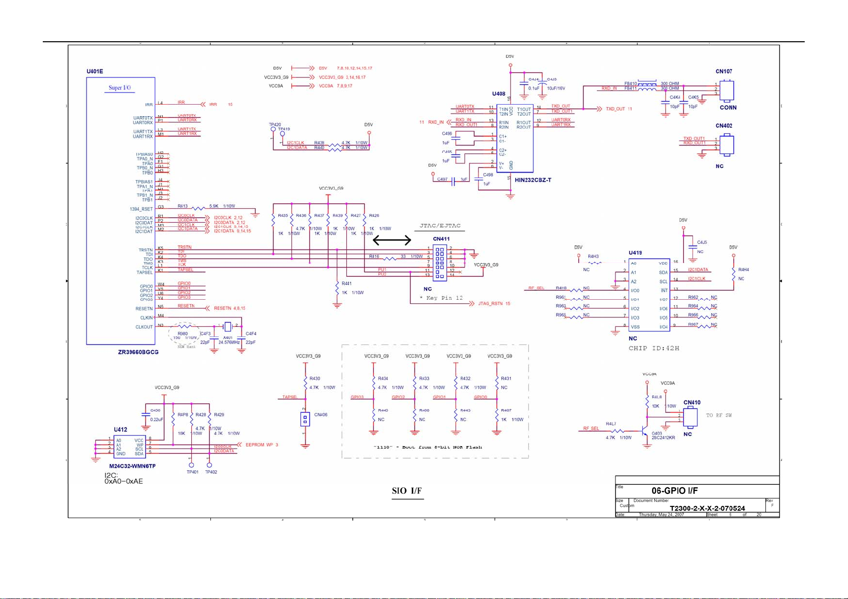
9. Schematic Diagram
9.1 Main Board
38
Page 39

42’’ LCD TV AOC L42W665
39
Page 40

42’’ LCD TV AOC L42W665
40
Page 41
42’’ LCD TV AOC L42W665
41
Page 42
42’’ LCD TV AOC L42W665
42
Page 43

42’’ LCD TV AOC L42W665
43
Page 44

42’’ LCD TV AOC L42W665
44
Page 45
42’’ LCD TV AOC L42W665
45
Page 46
42’’ LCD TV AOC L42W665
46
Page 47
42’’ LCD TV AOC L42W665
47
Page 48
42’’ LCD TV AOC L42W665
48
Page 49

42’’ LCD TV AOC L42W665
49
Page 50

42’’ LCD TV AOC L42W665
50
Page 51

42’’ LCD TV AOC L42W665
51
Page 52

42’’ LCD TV AOC L42W665
52
Page 53

42’’ LCD TV AOC L42W665
53
Page 54

42’’ LCD TV AOC L42W665
9.2 Power Board
BD901
1
D10XB60
R903
330K 1/4W
2
C908
470pF/250V
RV901
560
L903
124
10mH
R902
330K 1/4W
C904
0.047UF
L901
124
L
L902
124
10mH
C901
0.047UF
CN901
CONN
+
3
-
4
12
3
R901
330K 1/4W
C909
470pF/250V
3
3
123
R904
NC
C907
1uF/450V
R905
NC
R906
NC
R907
56K 1/8W
NR901
NTCR
C971
220pF
F901
FUSE
18K 1/8W
220KΩ 1/8W
VCC
C911
0.1uF
C905
0.0022uF/250V
R975
+
47uF/50V
C990
C972
0.22uF/25V
R947
R948
47 1/4W
47 1/4W
R949
L906
1
2
12
R909
15K 1/8W
R908
C912
C914
NC
NA
R976
10K
D902
FMX-G26S
5
6
168uH
11
R910
47
678
OUT
VCC
GND
IC901
FAN7529MX
INV
COMP
MOT
CS ZCD
123
4 5
R921
10K 1/8W
C915
0.047uF
0.1 ohm
R972
2M 1/4W
2M 1/4W
R974
2M
R977
27K 1/8W
R978
510K 1/8W
C974
0.0047uF
C913
56pF
KTD1624C
C917
1000pF
C916
0.33uF
R971
R973
IC971
1
Css
2
DELAY
3
CF
4
RFmin
5
STBY
6
ISEN
7
LINE
8 9
DIS PFC_STOP
L6599D
C973
0.1uF/50V
R911
2.2
Q903
Q904
KTB1124B
VBOOT
HVG
OUT
N.C.
GND
C977
0.1uF/50V
Vcc
LVG
C910
0.01uF/500V
10 1/8W
R914
10 1/8W
1MΩ 1% 1/4W
16
15
14
13
12
11
10
C976
5600PF
R979
100
R912
C979
0.1uF/50V
22 1/8W
22 1/8W
R920
470 1/4W
R9010
R9018
0 1/4W
R913
R915
C978
0.1uF/50V
C931
0.1uF
D903
LL4148
D904
LL4148
R917
10K 1/8W
VCC
R9011
1MΩ 1% 1/4W
R9012
1MΩ 1% 1/4W
R9013
240KΩ 1% 1/8W
D971
LL4148
R981
33 1/8W
100K 1/8W
D972
LL4148
R983
33 1/8W
+
C975
10uF/50V
R985
2.0K
R916
10K 1/8W
1
D978
LL4148
R982
1
2
STW20NM60
3
R922
39KΩ 1/8W
1
1
R984
100K 1/8W
Q902
R918
0.15 3W
Q901
2
STW20NM60
3
51KΩ 1/8W
C996
1uF
2
3
2
3
R986
0.68 3W
R919
0.15 3W
R923
Q971
STP20NM50/FP
Q972
STP20NM50/FP
R924
1.5M 1/4W
R925
1M 1/4W
R926
1M 1/4W
R9014
150KΩ 1% 1/8W
POWER X'FMR
6
7
3
4
C980
0.027uF/1000V
R980
3.9K
+
C918
100uF 450V
T971
43
VCC
8
9
13
14
10
11
R989
6.2K 1/8W
12
IC972
PC123X8YFZOF
C987
0.1uF/50V
IC973
AZ431AZ-AE1
+
C919
100uF 450V
R995
150K 1/4W
C937
10uF/50V
R9005
47 1/4W
R9006
47 1/4W
FME-220A
R990
3.3K 1/ 8W
R991
1KΩ 1/8W
D976
R9001
47 1/4W
R9002
47 1/4W
D975
+
FME-220A
Q932
KTD1691
+
R996
150K 1/4W
R9007
47 1/4W
R9008
47 1/4W
123
123
R9003
47 1/4W
R9004
47 1/4W
C986
0.1uF/50V
R993
1K 1/8W
C920
100uF 450V
R934
1K 1/8W
24V
C994
1000PF
+
C981
2200uF/35V
C992
1000PF
R992
24K 1/8W
R994
2.7K 1/8W
150K 1/4W
R9019
R931
0.1 ohm
R997
C999
0.01uF
1
BNO
2
COMP
3
(-)LATCH
4 5
CS GND
51K 1/8W
C934
1000pF
C933
0.01uF
1K 1/8W
IC931
LD7522PS
C993
1000PF
24V1
R998
C995
1000PF
+
C982
2200uF/35V
C923
470pF/50V
R941
C939
100K 2W
0.0022uF/2KV
D937
R999
BA159GPT
10K 1/8W
D977
+
R940
R9009
51 1/4W
C932
47uF/50V
24V
+
+
C926
NA
C938
100uF/50V
Q931
STP10NK70ZFP
R945
0.47 2W
R9015
62K/0805
C983
1000uF/35V
C921
0.1uF
D936
UF4003PT
D932
UF4003PT
R965
100K 1/8W
C927
0.0047uF
C997
0.1uF/50V
C935
LL4148
100n/0805
+
C998
10uF/50V
D931
LL4148
8
OVP
7
VCC
6
OUT
R939
22 1/8W
10K 1/8W
R946
470 1/8W
24V1
L971
3.0uH +-10%
R964
C924
0.47uF/25V
1M 1/8W
R942
4.7Ω 1/4W
R927
0Ω 1/4W
D973
LL4148
12
ZD933
RLZ27B
C984
1uF
+
C922
470uF/35V
R966
100K 1/4W
1
RC
2
SS
3
COMP
4 5
FB GND
POWER X'FMR
1
2
3
6
5
Q973
2N3904S-RTK/PS
D974
LL4148
12
ZD934
RLZ18B
R987
5.1K 1/4W
VDD
ISNS
GDRV
IC960
TPS40200DR
T931
7
8
9
10
11
12
43
R988
5.1K 1/4W
Q960
AO4411
1
S
D
2
S
D
3
S
D
4
G
D
8
7
6
R950
47 1/4W
47 1/4W
R952
R951
47 1/4W
47 1/4W
R954
R953
47 1/4W
47 1/4W
3
D951
FME-220A
2
1
R955
470 1/4W
12
R956
IC932
1K 1/8W
PC123X8YFZOF
C940
NC
R957
C941
0.1uF/50V
10KΩ 1/8W
IC933
AZ431AZ-AE1
+24V
L960
20uH
8
7
6
R967
5
22 1/4W
D960
SSM54PT
C929
0.001uF
C928
1uF
R968
20K 1/8W
C930
1500PF/50V
T P V ( Top Victory Electronic s Co . , Ltd. )
絬 隔 瓜 絪 腹
Key Component
Date
3300PF/50V
C948
1000PF
T2512-1-X-X-2-070403
02.POWER
C943
R969
62K 1/8W
R970
3K 1/8W
3300PF/50V
C949
1000PF
C953
1uF
C944
C945
3300PF/50V
3
D950
FME-210B
2
+
C946
1
1000uF/25V
R958
33K 1/8W
R960
NC
ZD931
PTZ9.1B
L932
1 2
3.5uH
+
C951
+
C950
1000uF/16V
1000uF/16V
R959
3.6K 1/8W
ZD932
RLZ15B
R961
2.4K 1/ 8W
+5V
F902
0 1/4W
+15V
+
C954
470uF/25V
OEM MODEL Size
TPV MODE L
PCB NAME
Sheet
L931
3.5uH
470uF/25V
715T2512-2
22Wednesday , May 23, 2007
of
C947
43
1 2
+
C952
470uF/16V
PS ON
R9016
3K 1/8W
R9017
3K 1/8W
+15V
+12V
+24V
+
12
IC934
PC123X8YFZOF
Q933
2N3904S-RTK/PS
+12V
+5V
R962
1K 1/8W
R963
10K 1/8W
C942
1uF
PS ON
CN902
1
2
3
4
5
6
7
8
9
10
11
12
CONT
CN903
1
2
3
4
5
6
7
8
9
10
11
12
13
14
CN904
1
2
3
4
5
6
7
8
9
10
11
12
13
14
Custom
1
Rev
<
称爹
>
称爹
54
Page 55
42’’ LCD TV AOC L42W665
9.3 IR Board
55
Page 56

42’’ LCD TV AOC L42W665
9.4 Key Board
56
Page 57

42’’ LCD TV AOC L42W665
9.5 Side Board
57
Page 58

42’’ LCD TV AOC L42W665
9.6 Audio Board
58
Page 59

42’’ LCD TV AOC L42W665
10. Exploded View
59
Page 60
42″ LCD TV AOC L42W665
11. BOM List
E427AZNS2WA2NN
Location TPV Part No. Description
001T6020 1 SCREW-SPE CIAL
026T 800504 3 BARCODE LABEL
033T 465 1 CLIP JOINTER
041T780061532C SA CENTER LIST
044T6002709 3A PAPER BOARD
044T9003 3 CORNER PAPER
050T 500 1 CABLE TIE
052T 1185 MIDDLE TAPE FOR CARTON
052T 1186 SMALL TAPE
052T 1207 A ALUMINIUM TAPE
052T 1211 A ADHESIVE TYPE
052T 1211 B ADHESIVE TYPE
052T6019 1 YELLOW TAPE
089T 17356G554 AUDIO CABLE
089T 725HAA 1 SIGNAL CBALE
089T402A15N IS POWER CORD
092TB1JX1A21GM BATTERY LR06 XINLI
095T8013 3 38 WIRE HARNESS
095T8013 2D 58 HARNESS 2P 900MM
095T8013 3D 55 HARNESS 3P 850MM
095T8013 3D 63 HARNESS 3P 430MM
095T8013 6D 30 HARNESS 6P-6P 230M
095T801313D 12 HARNESS 13P-5P+ 8P 1050MM
095T801412D 84 HARNESS 12P+ 4P+ 9P-12P 340MM
095T801414D 88 HARNESS 14P-10P+4P 950MM
095T801414D 89 HARNESS 14P-14P 380MM
095T801830D156 HARNESS 30P-28P 250MM
098TR7BDINEACF REMOTE FUHUA FOR AOC
0M1T 930 4120 SCREW
0M1T 940 6120 SCREW
0M1T 940 8 47 CR3 SCREW
0M1T1140 6120 SCREW 4*6MM
0M1T1730 6120 SCREW 3*6MM
0Q1T 330 6120 SCREW
0Q1T 330 8 47 CR3 SCREW
0Q1T 930 6120 SCREW
0Q1T 940 10120 SCREW
0Q1T 940 16 47 CR3 SCREW
0Q1T1840 10120 SCREW
705TQ715040 BKT ASS'Y
0M1T 930 6120 SCREW M3-0.5X6
PTPF7AA6 SIDE BOARD
CN004 033T380214H WAFER
CN010 088T 30221T CL PHONE JACK 7PIN DARK GARY
CN011 088T 78Z 3Y C RCA JACK VERTICAL 1*3 Y/W/R
CN003 088T100Z 51CL S-5
R111 061T0603000 CHIP 0OHM 1/16W
R112 061T0603000 CHIP 0OHM 1/16W
R113 061T0603000 CHIP 0OHM 1/16W
R003 061T0603473 CHIP 47KOHM 1/16W
R002 061T0603473 CHIP 47KOHM 1/16W
R001 061T0603473 CHIP 47KOHM 1/16W
R004 061T0603473 CHIP 47KOHM 1/16W
60
Page 61

42″ LCD TV AOC L42W665
C101 065T0603101 31 CHIP 100PF 50V NPO
C102 065T0603101 31 CHIP 100PF 50V NPO
C107 065T0603101 31 CHIP 100PF 50V NPO
C105 065T0603101 31 CHIP 100PF 50V NPO
C106 065T0603101 31 CHIP 100PF 50V NPO
C104 065T0603101 31 CHIP 100PF 50V NPO
C103 065T0603101 31 CHIP 100PF 50V NPO
C108 065T0603102 32 CHIP 1000PF 50V X7R
C109 065T0603102 32 CHIP 1000PF 50V X7R
FB001 071T 56G301 EA CHIP BEAD 300 OHM 0805
FB002 071T 56G301 EA CHIP BEAD 300 OHM 0805
Z007 093T 64 37 N V-PORT-0603-100K V05
Z006 093T 64 37 N V-PORT-0603-100K V05
Z005 093T 64 37 N V-PORT-0603-100K V05
Z004 093T 64 37 N V-PORT-0603-100K V05
Z003 093T 64 37 N V-PORT-0603-100K V05
Z002 093T 64 37 N V-PORT-0603-100K V05
Z001 093T 64 37 N V-PORT-0603-100K V05
715T2532 1 SIDE BOARD PCB
Q15T0152 1 BKT_VIDEO
Q36T 600 37 1 HIMERON
705TQ734115 REAR COVER ASS'Y
A34T0282 GMA1A 30 REAR COVER 42"
A34T0283 GM 1A COVER_SPK
Q36T 600 35 16 HIMERON
Q36T 600 36 13 HIMERON
Q36T 600 37 1 HIMERON
Q36T 600 37 15 CLOTH_GRIDDING
Q36T 600 37 16 HIMERON
Q36T 600 43 1 HIMERON
Q36T 600 46 1 HIMERON
Q44T3231 21 29 EVA WASHER
705TQ734116 STAND/BASE ASS'Y
0M1T 930 6120 SCREW M3-0.5X6
0Q1T 130 8120 SCREW
A34T0284 KG 1L 33 BASE_S1
A34T0285 KG 1L STAND_A1
Q12T7027 1 RUBBER FOOT
Q15T0145A01 BASE PLATE A1
Q15T0149A01 BKT STAND
705TQ734267 BEZEL ASS'Y
078T 451 5 SPEAKER 8 OHM 15W 150X57.5MM
0Q1T 930 6120 SCREW
A33T0138 GMB1L 30 COVER_FUNCTION
A33T0139 AI 1L BUTTON_FUNCTION
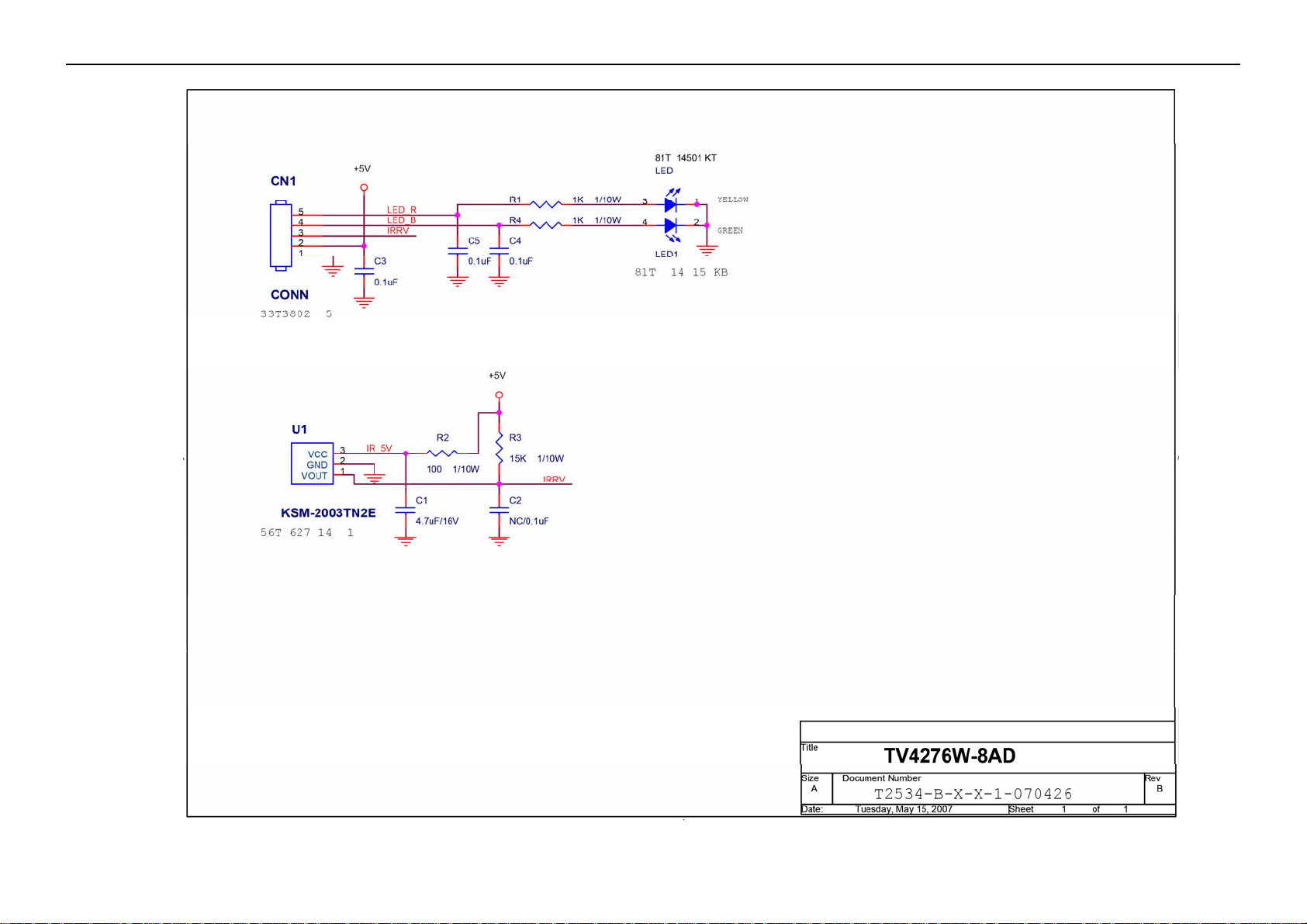
IRPF7QA4 IR BOARD
CN1 033T3802 5 AUDIO IN
U1 056T 627 14 1 IC KSM-2003TN2E 37.9KHZ
R2 061T0603101 CHIP 100OHM 1/16W
R1 061T0603102 CHIP 1K OHM 1/16W
R4 061T0603102 CHIP 1K OHM 1/16W
R3 061T0603153 RST CHIPR 15 KOHM +-5% 1/10W
C5 065T0603104 32 CHIP 0.1UF 50V X7R
C3 065T0603104 32 CHIP 0.1UF 50V X7R
C4 065T0603104 32 CHIP 0.1UF 50V X7R
C1 065T0805475 15 CHIP 4.7UF 16V X5R
61
Page 62

42″ LCD TV AOC L42W665
LED1 081T 14501 KT LED
715T2534 1 IR BOARD PCB
KEPF6AA6 KEY BOARD
CN21 033T8027 8 H WAFER
SW25 077T 600 1GCJ TACT SWITCH TSPB-2 -NP
SW26 077T 600 1GCJ TACT SWITCH TSPB-2 -NP
SW27 077T 600 1GCJ TACT SWITCH TSPB-2 -NP
SW23 077T 600 1GCJ TACT SWITCH TSPB-2 -NP
SW24 077T 600 1GCJ TACT SWITCH TSPB-2 -NP
SW22 077T 600 1GCJ TACT SWITCH TSPB-2 -NP
SW21 077T 600 1GCJ TACT SWITCH TSPB-2 -NP
C24 065T0603104 32 CHIP 0.1UF 50V X7R
C25 065T0603104 32 CHIP 0.1UF 50V X7R
C26 065T0603104 32 CHIP 0.1UF 50V X7R
C22 065T0603104 32 CHIP 0.1UF 50V X7R
C23 065T0603104 32 CHIP 0.1UF 50V X7R
C21 065T0603104 32 CHIP 0.1UF 50V X7R
C20 065T0603104 32 CHIP 0.1UF 50V X7R
715T2470 1 KEY BOARD PCB
Q44T3121510528 PU FOAM
705TQ787009 AC SOCKET ASS'Y
087T 501 7 AC SOCKET 3PIN
095T 900 42 WIRE HARNESS
096T 29 6 SHRINK TUBE UL/CSA
0M1T 130 6 47 CR3 SCREW
A15T0176A02 BKT_IO_BOTTOM
PTPFFA2P PLUG BOARD
CN108 033T3278 3 WAFER
CN109 088T 353 9M H DB9 RIGHT AMGLE MALE
PCB 715T1877 1 CONNECT BOARD PCB
750TVUT0W1511N PANEL T420XW01 V500 TW AUO
A15T0174A02 BKT_PCB_HOLDER
A15T0175 2 BKT-IO-TOP
A33T0141 1 1C POWER LENS
A33T0142 ED 1C IR LENS
A34T0281 KGB1L 30 BEZEL_TV42W-7A1
A85T0051 1 COVER-SHIELD
ADPC24250E1P ADAPTER BOARD
CN902 033T3278 12 12P PLUG B12B-XHA/JS B12B-XHA/
CN903 033T3802 10 PLUG
CN904 033T3802 14 CONN
CN901 033T8029 3A WAFER 2P 3.96MM
040T 45762420A GP S/N LABEL
IC932 056T 139 3B IC PC123Y82FZ0F
IC934 056T 139 3B IC PC123Y82FZ0F
IC972 056T 139 3B IC PC123Y82FZ0F
Q932 057T 761 7 KTD1691P
R945 061T 2J47864D RST WWR 0.47 OHM +-5% 2W
RV901 061T 46 17 VARISTOR 560V TNR14V561K
R918 061T 20K158GB1 RST CEMENTR 0.15 OHM +-10% 5W
R919 061T 20K158GB1 RST CEMENTR 0.15 OHM +-10% 5W
R971 061T 303108 59 RST FUSER 0.1 OHM +-5% 1W
R931 061T 303108 64 RST FUSER 0.1 OHM +-5% 1W
R941 061T152M104 64 100K0HM2W
R986 061T153M688 59 RST MOFR 0.68 OHM +-5% 3WS
C904 063T107K474 US X2 CAP 0.47UF K 275VAC
62
Page 63

42″ LCD TV AOC L42W665
C901 063T107K474 US X2 CAP 0.47UF K 275VAC
C980 063T210J2735C2 MPP 27NF J 1000V
C907 063T213J105GFA MPF CAP
C939 065T 2K222 1A6921 CAP CER 2200PF K 2KV
C908 065T306K4712BP 470PF +-10% 250VAC
C909 065T306K4712BP 470PF +-10% 250VAC
C905 065T306M2222BP Y1.CAP.0022UF 250V AC
C910 065T517K103 2B GP CK45B2H103KYJ 0.01UF 500V
C920 067T 40C10115K EC CAP 100UF 450V 18*35MM
C919 067T 40C10115K EC CAP 100UF 450V 18*35MM
C918 067T 40C10115K EC CAP 100UF 450V 18*35MM
C981 067T215D2226KV EC CAP 2200UF 35V 18*25MM
C982 067T215D2226KV EC CAP 2200UF 35V 18*25MM
C947 067T215D4714KV
C954 067T215D4714KV
C950 067T215S1023KV
C951 067T215S1023KV
C946 067T215S1024KV
C983 067T215S1026KV EC CAP 1000UF 35V 12.5*25MM
C952 067T215S4713KV
C922 067T215S4716KV
L901 073L 174 52 LG CHOKE COIL
L906 073T 174103 YS PFC CHOKE 168UH YS04160066
L902 073T 174105 YS LINE FILTER 10MH YS04120043
L903 073T 174105 YS LINE FILTER 10MH YS04120043
L931 073T 253 91 H CHOKE COIL
L932 073T 253 91 H CHOKE COIL
L971 073T 253150 L CHOCK
L960 073T 253194 L CHOKE COIL 20UH CC-008064
T971 080TL42T 12 YS X'FMR 500UH YS04160065
T931 080TL42T 13 YS X'FMR 820UH YS04160067
705TQ757004 Q931 ASS'Y
Q931 057T 667 21 STP10NK70ZFP
HS8 090T 425502 HEAT SINK
0M1T1730 8120 SCREW
705TQ761010 NR901 ASS'Y
NR901 061T 58030 WL RST NTCR 3 OHM +-20% 5A THINKING
Q09T 203 8 PIN
705TQE57001 Q901/Q902/D902 ASS'Y
012T 372 2 SILICON
Q901 057T 667 25 STW20NM60
Q902 057T 667 25 STW20NM60
D902 093T 220 23 DIODE FMX-G26S TO-220 SANKEN
0M1T1730 10120 SCREW
0M1T1730 12128 SCREW
HS2 Q90T0097B01 HEAT SINK
705TQE57003 Q971/Q972 ASS'Y
Q972 057T 667 29 STP20NM50/FP
Q971 057T 667 29 STP20NM50/FP
0M1T1730 10120 SCREW
705TQE93001 D950/D951 ASS'Y
D950 093T 60239 FME-210B T0-220
D951 093T 60247 DIODE FME-220A TO-220 SANKEN
0M1T1730 8120 SCREW
HS1 Q90T0095A01 HEAT SINK
705TQE93002 D975/D976 ASS'Y
EC 105℃ CAP 470UF M 25V
EC 105℃ CAP 470UF M 25V
EC 105℃ CAP 1000UF M 16V
EC 105℃ CAP 1000UF M 16V
EC 105℃ CAP 1000UF M 25V
EC 105℃ CAP 470UF M 16V
CAP 105℃ 470UF M 35V
63
Page 64

42″ LCD TV AOC L42W665
D976 093T 60247 DIODE FME-220A TO-220 SANKEN
D975 093T 60247 DIODE FME-220A TO-220 SANKEN
0M1T1730 10120 SCREW
HS4 Q90T0096A01 HEAT SINK
705TQE93003 BD901 ASS'Y
BD901 093T 50460 18 D10XB60
0M1T1730 10120 SCREW
HS6 Q90T0132 1 HEAT SINK
IC901 056T 368 12 IC FAN7529MX SOP-8
IC931 056T 379 79 IC LD7522PS SOP-8
IC960 056T 379 84 IC TPS40200DR SOIC-8
IC971 056T 665 10 1 IC RESONANT L6599D SO-16N ST
Q973 057T 417 12 T TRA 2N3904S-RTK/PS SOT-23 KEC
Q933 057T 417 12 T TRA 2N3904S-RTK/PS SOT-23 KEC
Q903 057T 761 11 TRA KTD1624C SOT-89 KEC
Q904 057T 761 12 TRA KTB1124B SOT-89 KEC
Q960 057T 763 3 AO4411L SO-8 BY AOS SMT
R912 061T0805100 RST CHIPR 10 OHM +-5% 1/8W
R914 061T0805100 RST CHIPR 10 OHM +-5% 1/8W
R956 061T0805102 RST CHIPR 1KOHM +-5% 1/4W
R962 061T0805102 RST CHIPR 1KOHM +-5% 1/4W
R998 061T0805102 RST CHIPR 1KOHM +-5% 1/4W
R934 061T0805102 RST CHIPR 1KOHM +-5% 1/4W
R991 061T0805102 RST CHIPR 1KOHM +-5% 1/4W
R993 061T0805102 RST CHIPR 1KOHM +-5% 1/4W
R916 061T0805103 RST CHIPR 10 KOHM +-5% 1/8W
R917 061T0805103 RST CHIPR 10 KOHM +-5% 1/8W
R921 061T0805103 RST CHIPR 10 KOHM +-5% 1/8W
R940 061T0805103 RST CHIPR 10 KOHM +-5% 1/8W
R963 061T0805103 RST CHIPR 10 KOHM +-5% 1/8W
R999 061T0805103 RST CHIPR 10 KOHM +-5% 1/8W
R957 061T0805103 RST CHIPR 10 KOHM +-5% 1/8W
R965 061T0805104 RST CHIPR 100 KOHM +-5% 1/8W
R984 061T0805104 RST CHIPR 100 KOHM +-5% 1/8W
R982 061T0805104 RST CHIPR 100 KOHM +-5% 1/8W
R964 061T0805105 RST CHIPR 1 MOHM +-5% 1/8W
R9014 061T0805150 3F RST CHIPR 150 KOHM +-1% 1/8W
R909 061T0805153 RST CHIPR 15 KOHM +-5% 1/8W
R975 061T0805180 2F RST CHIPR 18 KOHM +-1% 1/8W
R968 061T0805203 RST CHIPR 20 KOHM +-5% 1/8W
R913 061T0805220 RST CHIPR 22 OHM +-5% 1/8W
R915 061T0805220 RST CHIPR 22 OHM +-5% 1/8W
R939 061T0805220 RST CHIPR 22 OHM +-5% 1/8W
R908 061T0805224 RST CHIPR 220 KOHM +-5% 1/8W
R961 061T0805240 1F RST CHIPR 2.4 KOHM +-1% 1/8W
R9013 061T0805240 3F RST CHIPR 240 KOHM +-1% 1/8W
R992 061T0805243 RST CHIPR 24 KOHM +-5% 1/8W
R994 061T0805272 RST CHIPR 2.7 KOHM +-5% 1/8W
R977 061T0805273 RST CHIPR 27 KOHM +-5% 1/8W
R970 061T0805302 RST CHIPR 3 KOHM +-5% 1/8W
R9016 061T0805302 RST CHIPR 3 KOHM +-5% 1/8W
R9017 061T0805302 RST CHIPR 3 KOHM +-5% 1/8W
R983 061T0805330 RST CHIPR 33 OHM +-5% 1/8W
R981 061T0805330 RST CHIPR 33 OHM +-5% 1/8W
R958 061T0805330 2F RST CHIPR 33 KOHM +-1% 1/8W
R990 061T0805332 RST CHIPR 3.3 KOHM +-5% 1/8W
64
Page 65

42″ LCD TV AOC L42W665
R959 061T0805360 1F RST CHIPR 3.6 KOHM +-1% 1/8W
R922 061T0805393 RST CHIPR 39 KOHM +-5% 1/8W
R946 061T0805471 RST CHIPR 470 OHM +-5% 1/8W
R9019 061T0805513 RST CHIPR 51 KOHM +-5% 1/8W
R923 061T0805513 RST CHIPR 51 KOHM +-5% 1/8W
R978 061T0805514 RST CHIPR 510KOHM +-5% 1/8W
R907 061T0805563 RST CHIPR 56 KOHM +-5% 1/8W
R969 061T0805620 2F RST CHIPR 62 KOHM +-1% 1/8W
R9015 061T0805620 2F RST CHIPR 62 KOHM +-1% 1/8W
R989 061T0805622 RST CHIPR 6.2 KOHM +-5% 1/8W
R9018 061T1206000 RST CHIPR 0 OHM +-5% 1/4W
F902 061T1206000 RST CHIPR 0 OHM +-5% 1/4W
R927 061T1206000 RST CHIPR 0 OHM +-5% 1/4W
R9010 061T1206100 4F RST CHIPR 1 MOHM +-1% 1/4W
R925 061T1206100 4F RST CHIPR 1 MOHM +-1% 1/4W
R9012 061T1206100 4F RST CHIPR 1 MOHM +-1% 1/4W
R9011 061T1206100 4F RST CHIPR 1 MOHM +-1% 1/4W
R996 061T1206150 3F RST CHIPR 150KOHM +-1% 1/4W
R997 061T1206150 3F RST CHIPR 150KOHM +-1% 1/4W
R924 061T1206155 RST CHIPR 1.5 MOHM +-5% 1/4W
R972 061T1206205 RST CHIPR 2 MOHM +-5% 1/4W
R973 061T1206205 RST CHIPR 2 MOHM +-5% 1/4W
R967 061T1206220 RST CHIPR 22 OHM +-5% 1/4W
R903 061T1206334 RST CHIPR 330 KOHM +-5% 1/4W
R902 061T1206334 RST CHIPR 330 KOHM +-5% 1/4W
R901 061T1206334 RST CHIPR 330 KOHM +-5% 1/4W
R947 061T1206470 RST CHIPR 47 OHM +-5% 1/4W
R948 061T1206470 RST CHIPR 47 OHM +-5% 1/4W
R949 061T1206470 RST CHIPR 47 OHM +-5% 1/4W
R950 061T1206470 RST CHIPR 47 OHM +-5% 1/4W
R951 061T1206470 RST CHIPR 47 OHM +-5% 1/4W
R952 061T1206470 RST CHIPR 47 OHM +-5% 1/4W
R9008 061T1206470 RST CHIPR 47 OHM +-5% 1/4W
R9007 061T1206470 RST CHIPR 47 OHM +-5% 1/4W
R9006 061T1206470 RST CHIPR 47 OHM +-5% 1/4W
R9005 061T1206470 RST CHIPR 47 OHM +-5% 1/4W
R9004 061T1206470 RST CHIPR 47 OHM +-5% 1/4W
R9003 061T1206470 RST CHIPR 47 OHM +-5% 1/4W
R9002 061T1206470 RST CHIPR 47 OHM +-5% 1/4W
R9001 061T1206470 RST CHIPR 47 OHM +-5% 1/4W
R954 061T1206470 RST CHIPR 47 OHM +-5% 1/4W
R953 061T1206470 RST CHIPR 47 OHM +-5% 1/4W
R942 061T1206479 RST CHIPR 4.7 OHM +-5% 1/4W
R987 061T1206512 RST CHIPR 5.1KOHM +-5% 1/4W
R988 061T1206512 RST CHIPR 5.1KOHM +-5% 1/4W
C917 065T0805102 31 1000PF 50V NPO
C934 065T0805102 31 1000PF 50V NPO
C948 065T0805102 32 CHIP 1000PF 50V X7R 0805
C949 065T0805102 32 CHIP 1000PF 50V X7R 0805
C992 065T0805102 32 CHIP 1000PF 50V X7R 0805
C993 065T0805102 32 CHIP 1000PF 50V X7R 0805
C994 065T0805102 32 CHIP 1000PF 50V X7R 0805
C995 065T0805102 32 CHIP 1000PF 50V X7R 0805
C929 065T0805102 32 CHIP 1000PF 50V X7R 0805
C933 065T0805103 32 10NF/50V/0805/X7R
C999 065T0805103 32 10NF/50V/0805/X7R
65
Page 66

42″ LCD TV AOC L42W665
C911 065T0805104 32 CHIP 0.1UF 50V X7R
C931 065T0805104 32 CHIP 0.1UF 50V X7R
C935 065T0805104 32 CHIP 0.1UF 50V X7R
C921 065T0805104 32 CHIP 0.1UF 50V X7R
C941 065T0805104 32 CHIP 0.1UF 50V X7R
C973 065T0805104 32 CHIP 0.1UF 50V X7R
C977 065T0805104 32 CHIP 0.1UF 50V X7R
C978 065T0805104 32 CHIP 0.1UF 50V X7R
C979 065T0805104 32 CHIP 0.1UF 50V X7R
C986 065T0805104 32 CHIP 0.1UF 50V X7R
C987 065T0805104 32 CHIP 0.1UF 50V X7R
C997 065T0805104 32 CHIP 0.1UF 50V X7R
C928 065T0805105 37 CHIP 1UF 50V Y5V
C953 065T0805105 37 CHIP 1UF 50V Y5V
C996 065T0805105 37 CHIP 1UF 50V Y5V
C984 065T0805105 37 CHIP 1UF 50V Y5V
C942 065T0805105 37 CHIP 1UF 50V Y5V
C930 065T0805152 32 CHIP 1500PF 50V X7R 0805
C971 065T0805221 31 220PF 50V NPO
C972 065T0805224 22 CAIP CAP 0.22 UF 25V X7R
C945 065T0805332 32 CAP 0805 3300PF K 50V X7R
C944 065T0805332 32 CAP 0805 3300PF K 50V X7R
C943 065T0805332 32 CAP 0805 3300PF K 50V X7R
C916 065T0805334 32 CHIP 0.33UF 50V X7R 0805
C923 065T0805471 31 CHIP 470PF 50V NPO
C974 065T0805472 32 MLCC 0805 CAP 4700PF K 50V X7R
C927 065T0805472 32 MLCC 0805 CAP 4700PF K 50V X7R
C915 065T0805473 32 CHIP 0.047UF 50V X7R
C924 065T0805474 22 CHIP 0.47UF 25V X7R
C913 065T0805560 31 MLCC 0805 CAP 56PF J 50V NPO
C976 065T0805562 32 CAP 0805 5600PF K 50V X7R
D978 093T 6432V LL4148-GSO8 SMD BY VISHA
D977 093T 6432V LL4148-GSO8 SMD BY VISHA
D974 093T 6432V LL4148-GSO8 SMD BY VISHA
D973 093T 6432V LL4148-GSO8 SMD BY VISHA
D904 093T 6432V LL4148-GSO8 SMD BY VISHA
D903 093T 6432V LL4148-GSO8 SMD BY VISHA
D931 093T 6432V LL4148-GSO8 SMD BY VISHA
D972 093T 6432V LL4148-GSO8 SMD BY VISHA
D971 093T 6432V LL4148-GSO8 SMD BY VISHA
ZD932 093T 39S 15 T RLZ15B
ZD931 093T 39S 38 T PTZ 9.1B
ZD933 093T 39S 42 T RLZ27B LLDS
ZD934 093T 39S 44 T RLZ18B
D960 093T5004 2 5A 40V
IC933 056T 158 10 T IC AZ431AZ-AE1 TO-92 AAC
IC973 056T 158 10 T IC AZ431AZ-AE1 TO-92 AAC
R995 061T 17215452T RST CFR 150KOHM +-5% 1/4W
R920 061T 17247152T 470OHM 5% 1/4W
R955 061T 17247152T 470OHM 5% 1/4W
R9009 061T 17251052T RST CFR 51 OHM +-5% 1/4W
R966 061T 20010452T 100K OHM 1/4W 1%
R979 061T 21010152T RST MFR 100 OHM +-1% 1/6W
R976 061T 21010352T RST MFR 10KOHM +-1% 1/6W
R980 061T 21039252T RST MFR 3.9KOHM +-1% 1/6W
R985 061T 60220252T CFR 2K C 5% 1/6W
66
Page 67

42″ LCD TV AOC L42W665
R974 061T 60220552T RST CFR 2MOHM +-5% 1/6W
R911 061T 60222952T 2.2 OHM +-5% 1/6W
R910 061T 60247052T CFR 47OHM +-5% 1/6W
R926 061T214Y10552T RST MGFR 1 MOHM +-5% 1/4W
C998 067T215Y1007KT EC105 10U 50V KEM50V
C975 067T215Y1007KT EC105 10U 50V KEM50V
C937 067T215Y1007KT EC105 10U 50V KEM50V
C938 067T215Y1017NT EC 100UF 50V 8*11.5MM
C932 067T215Y4707KT 47UF 50V
C912 067T215Y4707KT 47UF 50V
F901 084T 55 4 FUSE 382-5A 250V WICKMANN
D936 093T1020 752T UF4003PT
D932 093T1020 752T UF4003PT
D937 093T1100 1052T BA159GPT
J921 095T 90 23 JUMP WIRE
J920 095T 90 23 JUMP WIRE
J919 095T 90 23 JUMP WIRE
J918 095T 90 23 JUMP WIRE
J917 095T 90 23 JUMP WIRE
J916 095T 90 23 JUMP WIRE
J915 095T 90 23 JUMP WIRE
J914 095T 90 23 JUMP WIRE
J913 095T 90 23 JUMP WIRE
J912 095T 90 23 JUMP WIRE
J910 095T 90 23 JUMP WIRE
J909 095T 90 23 JUMP WIRE
J908 095T 90 23 JUMP WIRE
J907 095T 90 23 JUMP WIRE
J906 095T 90 23 JUMP WIRE
J922 095T 90 23 JUMP WIRE
J902 095T 90 23 JUMP WIRE
J911 095T 90 23 JUMP WIRE
J904 095T 90 23 JUMP WIRE
J903 095T 90 23 JUMP WIRE
J935 095T 90 23 JUMP WIRE
J934 095T 90 23 JUMP WIRE
J933 095T 90 23 JUMP WIRE
J932 095T 90 23 JUMP WIRE
J931 095T 90 23 JUMP WIRE
J930 095T 90 23 JUMP WIRE
J929 095T 90 23 JUMP WIRE
J928 095T 90 23 JUMP WIRE
J927 095T 90 23 JUMP WIRE
J925 095T 90 23 JUMP WIRE
J924 095T 90 23 JUMP WIRE
J923 095T 90 23 JUMP WIRE
J905 095T 90 23 JUMP WIRE
J901 095T 90 23 JUMP WIRE
715T2512 2 POWER BOARD PCB
AUPF7QA1 AUDIO BOARD
CN3 033T3278 2 WAFER
CN1 033T3278 3 WAFER
CN7 033T3278 6 WAFER
CN6 033T3802 4 WAFER PH-4
C3 064T176J474 0T 0.47UF +-5% 50/63V
C39 064T176J474 0T 0.47UF +-5% 50/63V
67
Page 68

42″ LCD TV AOC L42W665
C44 067T 215101 6P
C15 067T 215221 6P
C26 067T 215221 6P
L4 073T 253158 H CHOKE COIL 22UH+/-25%
L9 073T 253158 H CHOKE COIL 22UH+/-25%
L2 073T 253158 H CHOKE COIL 22UH+/-25%
L11 073T 253158 H CHOKE COIL 22UH+/-25%
U1 090T6068 2 HEAT SINK
U3 056T 593 17 NTM2761RB2
U2 056T 593 19 NJM2199 DMP14E
U1 056T 616 25 1 IC TPA3100D2PHPR HTQFP-48 TI
Q1 057T 765 1 2SC2412KR
Q5 057T 765 1 2SC2412KR
R33 061T0603000 CHIP 0OHM 1/16W
R7 061T0603000 CHIP 0OHM 1/16W
R5 061T0603000 CHIP 0OHM 1/16W
R39 061T0603000 CHIP 0OHM 1/16W
R26 061T0603000 CHIP 0OHM 1/16W
R25 061T0603101 CHIP 100OHM 1/16W
R1 061T0603103 CHIP 10KOHM 1/16W
R12 061T0603103 CHIP 10KOHM 1/16W
R28 061T0603103 CHIP 10KOHM 1/16W
R30 061T0603103 CHIP 10KOHM 1/16W
R4 061T0603103 CHIP 10KOHM 1/16W
R6 061T0603103 CHIP 10KOHM 1/16W
R17 061T0603104 CHIP 100K OHM 1/16W
R8 061T0603105 CHIP 1MOHM 1/16W
R37 061T0603120 1F RST CHIPR 1.2 KOHM +-1% 1/10W
R35 061T0603120 1F RST CHIPR 1.2 KOHM +-1% 1/10W
R34 061T0603160 2F RST CHIPR 16 KOHM +-1% 1/10W
R18 061T0603223 CHIP 22KOHM 1/16W
R36 061T0603330 1F RST CHIPR 3.3 KOHM +-1% 1/10W
R38 061T0603330 1F RST CHIPR 3.3 KOHM +-1% 1/10W
R14 061T0603333 RST CHIPR 33 KOHM +-5% 1/10W
R13 061T0603472 CHIP 4.7KOHM 1/16W
R15 061T0603473 CHIP 47KOHM 1/16W
R16 061T0603473 CHIP 47KOHM 1/16W
R29 061T0603512 RST CHIPR 5.1 KOHM +-5% 1/10W
R21 061T1210000 RST CHIPR 0 OHM +-5% 1/3W
R22 061T1210000 RST CHIPR 0 OHM +-5% 1/3W
R23 061T1210000 RST CHIPR 0 OHM +-5% 1/3W
R24 061T1210000 RST CHIPR 0 OHM +-5% 1/3W
C2 065T0603102 32 CHIP 1000PF 50V X7R
C38 065T0603102 32 CHIP 1000PF 50V X7R
C4 065T0603102 32 CHIP 1000PF 50V X7R
C40 065T0603102 32 CHIP 1000PF 50V X7R
C13 065T0603103 32 CHIP 0.01UF 50V X7R
C35 065T0603103 32 CHIP 0.01UF 50V X7R
C46 065T0603104 32 CHIP 0.1UF 50V X7R
C5 065T0603104 32 CHIP 0.1UF 50V X7R
C41 065T0603104 32 CHIP 0.1UF 50V X7R
C37 065T0603104 32 CHIP 0.1UF 50V X7R
C32 065T0603104 32 CHIP 0.1UF 50V X7R
C1 065T0603104 32 CHIP 0.1UF 50V X7R
C49 065T0603223 32 CHIP 0.022UF 50V X7R 0603
C50 065T0603224 32 MLCC 0603 0.22UF K 50V X7R
EC 105℃ 100UF M 35V
ELCAP 105℃ 220UF M 35V
ELCAP 105℃ 220UF M 35V
68
Page 69

42″ LCD TV AOC L42W665
C8 065T0603224 32 MLCC 0603 0.22UF K 50V X7R
C6 065T0603224 32 MLCC 0603 0.22UF K 50V X7R
C34 065T0603224 32 MLCC 0603 0.22UF K 50V X7R
C33 065T0603224 32 MLCC 0603 0.22UF K 50V X7R
C10 065T0603333 32 CHIP 0.033UF 50V X7R
C20 065T0603334 27 MLCC 0603 CAP 0.33UF Z 25V Y5V
C48 065T0603474 27 CHIP 0.47UF 25V Y5V
C47 065T0603474 27 CHIP 0.47UF 25V Y5V
C17 065T0603474 27 CHIP 0.47UF 25V Y5V
C9 065T0805105 37 CHIP 1UF 50V Y5V
C36 065T0805105 37 CHIP 1UF 50V Y5V
C30 065T0805105 37 CHIP 1UF 50V Y5V
C28 065T0805105 37 CHIP 1UF 50V Y5V
C27 065T0805105 37 CHIP 1UF 50V Y5V
C25 065T0805105 37 CHIP 1UF 50V Y5V
C23 065T0805105 37 CHIP 1UF 50V Y5V
C12 065T0805105 37 CHIP 1UF 50V Y5V
C31 065T1206106 17 CHIP 10UF 16V Y5V
C19 065T1206475 17 MLCC 1206 CAP 4.7UF Z 16V Y5V
C14 065T1206475 17 MLCC 1206 CAP 4.7UF Z 16V Y5V
C11 065T1206475 17 MLCC 1206 CAP 4.7UF Z 16V Y5V
C22 065T1206475 17 MLCC 1206 CAP 4.7UF Z 16V Y5V
C42 065T1206475 17 MLCC 1206 CAP 4.7UF Z 16V Y5V
C7 065T1206475 17 MLCC 1206 CAP 4.7UF Z 16V Y5V
C52 067T311F100 4T
C51 067T311F100 4T
C18 067T311F100 4T
C16 067T311F100 4T
C29 067T311F101 4T
L7 073T 253142 S IND SMD 100.0UH+-20% TAI CHANGIND
D3 093T 6432V LL4148-GSO8 SMD BY VISHA
715T2412 1 AUDIO BOARD PCB
CBPF7Z1KQ4 MAIN BOARD
CN107 033T3278 3 WAFER
CN600 033T3278 4 WAFER
CN418 033T3278 6 WAFER
CN100 033T3278 10 10 PLUG B10E-XHA/JST E10B-XHA/
CN419 033T3278 13 WAFER
CN905 033T3802 9 WAFER PH-9
CN901 033T3802 12 WAFER PH-12
CN407 033T8027 28 WAFER
040T 457624 1B CPU LABEL
040T 45762412B CBPC LABEL
SF701 053T 44 5 SAW FILTER EPCOS
R935 061T152M629 64 6.2 OHM 2W 5% MOF
R936 061T152M629 64 6.2 OHM 2W 5% MOF
R930 061T153M180 59 18 OHM 5% 3W
R931 061T153M180 59 18 OHM 5% 3W
C605 067T305V471 1P
C606 067T305V471 1P
SW401 077T 600 1GCJ TACT SWITCH TSPB-2 -NP
CN101 088T 78 13 8C RCA JACK
CN105 088T 78 13 9C RCA JACK
CN106 088T 78 1320C RCA JACK
CN104 088T 78 1344C RCA JACK 1+1 RCA+S B+B AV-S-01-B
CN103 088T 30214K PHONE JACK
EC 105℃ 10UF M 25V
EC 105℃ 10UF M 25V
EC 105℃ 10UF M 25V
EC 105℃ 10UF M 25V
EC 105℃ 100UF M 25V
EC 105℃ CAP 470UF M 6.3V
EC 105℃ CAP 470UF M 6.3V
69
Page 70

42″ LCD TV AOC L42W665
CN102 088T 35315F H DB15 RIGHT ANGLE FEMALE
U401 090T 372 2 HEAT SINK
U701 090T8007 1A HEAT SINK
X901 093T 2204S JZ CRYSTAL 4MHZ/30PF/49U/S JING ZHAN
X401 093T 2258B J 24.576MHZ/20PF/49US
X701 093T 2262B J CRYSTAL NXS25.000 AC 20PF HC-49/US NSK
TU701 094TNTATALL T TUNER DTT7611A THOMSON
U911 Q90T0054 1 HEAT SINK
FL900 053T 43 1 FILTER BULLWILL
FL901 053T 43 1 FILTER BULLWILL
FL902 053T 43 1 FILTER BULLWILL
FL903 053T 43 1 FILTER BULLWILL
U909 056T 133 23 R BA17809FP-E2
U908 056T 133 27 R IC BA05FP-E2 BY ROHM
U917 056T 158501 IC AZ431AN-AE1 SOT23-3 AAC
U601 056T 192 17 IC TL072CDT SO-8 ST
U903 056T 563 9 AIC1084PM
U906 056T 563 9 AIC1084PM
U907 056T 56314A IC AP1501-K5LA TO-263-5L ANACHIP
U911 056T 56314A IC AP1501-K5LA TO-263-5L ANACHIP
U504 056T 567 7 MST9883C-140 LQFP-80 BY MST
U500 056T 585 4A AP1117E33LA
U501 056T 585 4A AP1117E33LA
U910 056T 585 4A AP1117E33LA
U915 056T 585 4A AP1117E33LA
U402 056T 61550C NT5DS16M16CS-5T
U403 056T 61550C NT5DS16M16CS-5T
U600 056T 616 8 TPA6110A2DGNR
U107 056T 623 16 IC FSAV433MTCX-NL TSSOP-20BY FAIRCHILD
U417 056T 632 1 IC 74HC4066DQ BY PHILIPS
U108 056T 634 3 IC STV6415DD ST
U103 056T 637 2B IC 74HC4051D SO16
U104 056T 637 2B IC 74HC4051D SO16
U101 056T 638603 IC CS5340-CZZ CIRRUS
U702 056T 639 2 UPC3218GV-E1-A SSOP-8 NEC
U407 056T 643500 EM6353BX2SP3B-2.9
U401 056T 644600 IC ZR39660BGCG ZORAN
U408 056T 645 1 HIN232CB-T S016 INTERSIL
U701 056T 647 12 IC CAS-220/CS LQFP-100 ZORAN
U913 056T 662 4 RCLAMP0514M.TBT
U912 056T 662 4 RCLAMP0514M.TBT
U415 056T 662 4 RCLAMP0514M.TBT
U414 056T 662 4 RCLAMP0514M.TBT
U914 056T 665915 IC TMDS341APFCRG4 TQFP-80
U502 056T 7SZ 2P F IC NC7SZ02P5X SOT-23 FAIRCHILD
U916 056T1125172 X EZ4 P89LPC930FDH
U405 056T1130 3 CS4335-KSZ SOIC-8
U106 056T1133 34 M24C02-WMN6TP
U404 056T1133 88EZ7 IC M29W320EB70N6E TSOP48 ST
U412 056T113353A M24C32-WMN6TP
U503 056T4LVT 14 P IC 74LVT14D,118 BY SO-14 PHILIPS
U418 056T74HC 14 F IC MM74HC14MX SOIC-14
Q701 057T 417 10 BFR93A SOT-23
Q401 057T 758 1 FET 2N7002E VISHAY
Q402 057T 758 1 FET 2N7002E VISHAY
Q909 057T 758 1 FET 2N7002E VISHAY
70
Page 71

42″ LCD TV AOC L42W665
Q910 057T 758 1 FET 2N7002E VISHAY
Q912 057T 763 3 AO4411L SO-8 BY AOS SMT
Q911 057T 763 3 AO4411L SO-8 BY AOS SMT
Q908 057T 763 3 AO4411L SO-8 BY AOS SMT
Q111 057T 765 1 2SC2412KR
Q403 057T 765 1 2SC2412KR
Q901 057T 765 1 2SC2412KR
Q903 057T 765 1 2SC2412KR
Q905 057T 765 1 2SC2412KR
Q906 057T 765 1 2SC2412KR
Q907 057T 765 1 2SC2412KR
Q913 057T 765 1 2SC2412KR
Q914 057T 765 1 2SC2412KR
Q915 057T 765 1 2SC2412KR
Q110 057T 765 1 2SC2412KR
Q109 057T 765 1 2SC2412KR
Q108 057T 765 1 2SC2412KR
Q107 057T 765 1 2SC2412KR
Q106 057T 765 1 2SC2412KR
Q105 057T 765 1 2SC2412KR
Q104 057T 765 1 2SC2412KR
Q103 057T 765 1 2SC2412KR
Q102 057T 765 1 2SC2412KR
Q101 057T 765 1 2SC2412KR
Q100 057T 765 1 2SC2412KR
RP505 061T 125101 8 RST CHIP AR 8P4R 100 OHM +-5% 1/16W
RP504 061T 125101 8 RST CHIP AR 8P4R 100 OHM +-5% 1/16W
RP503 061T 125101 8 RST CHIP AR 8P4R 100 OHM +-5% 1/16W
RP502 061T 125101 8 RST CHIP AR 8P4R 100 OHM +-5% 1/16W
RP501 061T 125101 8 RST CHIP AR 8P4R 100 OHM +-5% 1/16W
RP500 061T 125101 8 RST CHIP AR 8P4R 100 OHM +-5% 1/16W
RP412 061T 125150 8 RST CHIP AR 8P4R 15 OHM +-5% 1/16W
RP411 061T 125150 8 RST CHIP AR 8P4R 15 OHM +-5% 1/16W
RP410 061T 125150 8 RST CHIP AR 8P4R 15 OHM +-5% 1/16W
RP409 061T 125150 8 RST CHIP AR 8P4R 15 OHM +-5% 1/16W
RP408 061T 125150 8 RST CHIP AR 8P4R 15 OHM +-5% 1/16W
RP407 061T 125150 8 RST CHIP AR 8P4R 15 OHM +-5% 1/16W
RP406 061T 125150 8 RST CHIP AR 8P4R 15 OHM +-5% 1/16W
RP405 061T 125150 8 RST CHIP AR 8P4R 15 OHM +-5% 1/16W
RP404 061T 125150 8 RST CHIP AR 8P4R 15 OHM +-5% 1/16W
RP403 061T 125150 8 RST CHIP AR 8P4R 15 OHM +-5% 1/16W
RP402 061T 125150 8 RST CHIP AR 8P4R 15 OHM +-5% 1/16W
RP401 061T 125150 8 RST CHIP AR 8P4R 15 OHM +-5% 1/16W
RP413 061T 125150 8 RST CHIP AR 8P4R 15 OHM +-5% 1/16W
RP414 061T 125150 8 RST CHIP AR 8P4R 15 OHM +-5% 1/16W
RP415 061T 125150 8 RST CHIP AR 8P4R 15 OHM +-5% 1/16W
RP416 061T 125150 8 RST CHIP AR 8P4R 15 OHM +-5% 1/16W
R4J0 061T0603000 CHIP 0OHM 1/16W
R4H9 061T0603000 CHIP 0OHM 1/16W
R157 061T0603000 CHIP 0OHM 1/16W
R158 061T0603000 CHIP 0OHM 1/16W
R159 061T0603000 CHIP 0OHM 1/16W
R1F7 061T0603000 CHIP 0OHM 1/16W
R1F8 061T0603000 CHIP 0OHM 1/16W
R4A5 061T0603000 CHIP 0OHM 1/16W
R4E6 061T0603000 CHIP 0OHM 1/16W
71
Page 72

42″ LCD TV AOC L42W665
R4G7 061T0603000 CHIP 0OHM 1/16W
R724 061T0603000 CHIP 0OHM 1/16W
R611 061T0603000 CHIP 0OHM 1/16W
R610 061T0603000 CHIP 0OHM 1/16W
R4T3 061T0603000 CHIP 0OHM 1/16W
R4T2 061T0603000 CHIP 0OHM 1/16W
R4T1 061T0603000 CHIP 0OHM 1/16W
R4P7 061T0603000 CHIP 0OHM 1/16W
R4N0 061T0603000 CHIP 0OHM 1/16W
R4M8 061T0603000 CHIP 0OHM 1/16W
R4L3 061T0603000 CHIP 0OHM 1/16W
R4L0 061T0603000 CHIP 0OHM 1/16W
R4K2 061T0603000 CHIP 0OHM 1/16W
R4K1 061T0603000 CHIP 0OHM 1/16W
R4J1 061T0603000 CHIP 0OHM 1/16W
R4J6 061T0603000 CHIP 0OHM 1/16W
R4J8 061T0603000 CHIP 0OHM 1/16W
R4K0 061T0603000 CHIP 0OHM 1/16W
R4S0 061T0603000 CHIP 0OHM 1/16W
R4Q9 061T0603000 CHIP 0OHM 1/16W
R968 061T0603000 CHIP 0OHM 1/16W
R957 061T0603000 CHIP 0OHM 1/16W
R956 061T0603000 CHIP 0OHM 1/16W
R952 061T0603000 CHIP 0OHM 1/16W
R944 061T0603000 CHIP 0OHM 1/16W
R938 061T0603000 CHIP 0OHM 1/16W
R920 061T0603000 CHIP 0OHM 1/16W
R1003 061T0603000 CHIP 0OHM 1/16W
R150 061T0603000 CHIP 0OHM 1/16W
R151 061T0603000 CHIP 0OHM 1/16W
R152 061T0603000 CHIP 0OHM 1/16W
R153 061T0603000 CHIP 0OHM 1/16W
R154 061T0603000 CHIP 0OHM 1/16W
R155 061T0603000 CHIP 0OHM 1/16W
R156 061T0603000 CHIP 0OHM 1/16W
R977 061T0603100 CHIP 10OHM 1/16W
R969 061T0603100 CHIP 10OHM 1/16W
R4P9 061T0603100 CHIP 10OHM 1/16W
R455 061T0603100 CHIP 10OHM 1/16W
R116 061T0603101 CHIP 100OHM 1/16W
R182 061T0603101 CHIP 100OHM 1/16W
R184 061T0603101 CHIP 100OHM 1/16W
R1H4 061T0603101 CHIP 100OHM 1/16W
R1H5 061T0603101 CHIP 100OHM 1/16W
R1H6 061T0603101 CHIP 100OHM 1/16W
R701 061T0603101 CHIP 100OHM 1/16W
R702 061T0603101 CHIP 100OHM 1/16W
R721 061T0603101 CHIP 100OHM 1/16W
R916 061T0603101 CHIP 100OHM 1/16W
R917 061T0603101 CHIP 100OHM 1/16W
R940 061T0603101 CHIP 100OHM 1/16W
R942 061T0603101 CHIP 100OHM 1/16W
R4F9 061T0603102 CHIP 1K OHM 1/16W
R4F8 061T0603102 CHIP 1K OHM 1/16W
R4A3 061T0603102 CHIP 1K OHM 1/16W
R467 061T0603102 CHIP 1K OHM 1/16W
72
Page 73

42″ LCD TV AOC L42W665
R462 061T0603102 CHIP 1K OHM 1/16W
R441 061T0603102 CHIP 1K OHM 1/16W
R439 061T0603102 CHIP 1K OHM 1/16W
R437 061T0603102 CHIP 1K OHM 1/16W
R435 061T0603102 CHIP 1K OHM 1/16W
R427 061T0603102 CHIP 1K OHM 1/16W
R426 061T0603102 CHIP 1K OHM 1/16W
R183 061T0603102 CHIP 1K OHM 1/16W
R1005 061T0603102 CHIP 1K OHM 1/16W
R1004 061T0603102 CHIP 1K OHM 1/16W
R4M2 061T0603102 CHIP 1K OHM 1/16W
C947 061T0603102 CHIP 1K OHM 1/16W
R4L9 061T0603102 CHIP 1K OHM 1/16W
R1011 061T0603102 CHIP 1K OHM 1/16W
R960 061T0603102 CHIP 1K OHM 1/16W
R918 061T0603102 CHIP 1K OHM 1/16W
R998 061T0603102 CHIP 1K OHM 1/16W
R985 061T0603102 CHIP 1K OHM 1/16W
R976 061T0603102 CHIP 1K OHM 1/16W
R932 061T0603102 CHIP 1K OHM 1/16W
R909 061T0603102 CHIP 1K OHM 1/16W
R513 061T0603102 CHIP 1K OHM 1/16W
R501 061T0603102 CHIP 1K OHM 1/16W
R500 061T0603102 CHIP 1K OHM 1/16W
R4M4 061T0603102 CHIP 1K OHM 1/16W
R1002 061T0603102 CHIP 1K OHM 1/16W
R4P8 061T0603103 CHIP 10KOHM 1/16W
R995 061T0603103 CHIP 10KOHM 1/16W
R994 061T0603103 CHIP 10KOHM 1/16W
R978 061T0603103 CHIP 10KOHM 1/16W
R953 061T0603103 CHIP 10KOHM 1/16W
R939 061T0603103 CHIP 10KOHM 1/16W
R725 061T0603103 CHIP 10KOHM 1/16W
R714 061T0603103 CHIP 10KOHM 1/16W
R709 061T0603103 CHIP 10KOHM 1/16W
R614 061T0603103 CHIP 10KOHM 1/16W
R612 061T0603103 CHIP 10KOHM 1/16W
R4Q8 061T0603103 CHIP 10KOHM 1/16W
R474 061T0603103 CHIP 10KOHM 1/16W
R473 061T0603103 CHIP 10KOHM 1/16W
R464 061T0603103 CHIP 10KOHM 1/16W
R179 061T0603103 CHIP 10KOHM 1/16W
R489 061T0603103 CHIP 10KOHM 1/16W
R4D9 061T0603103 CHIP 10KOHM 1/16W
R4E9 061T0603103 CHIP 10KOHM 1/16W
R4F0 061T0603103 CHIP 10KOHM 1/16W
R4F1 061T0603103 CHIP 10KOHM 1/16W
R4F2 061T0603103 CHIP 10KOHM 1/16W
R4F3 061T0603103 CHIP 10KOHM 1/16W
R4F4 061T0603103 CHIP 10KOHM 1/16W
R4F5 061T0603103 CHIP 10KOHM 1/16W
R4F6 061T0603103 CHIP 10KOHM 1/16W
R4J2 061T0603103 CHIP 10KOHM 1/16W
R4J9 061T0603103 CHIP 10KOHM 1/16W
R4K3 061T0603103 CHIP 10KOHM 1/16W
R4K4 061T0603103 CHIP 10KOHM 1/16W
73
Page 74

42″ LCD TV AOC L42W665
R4L8 061T0603103 CHIP 10KOHM 1/16W
R4N1 061T0603103 CHIP 10KOHM 1/16W
R178 061T0603103 CHIP 10KOHM 1/16W
R177 061T0603103 CHIP 10KOHM 1/16W
R176 061T0603103 CHIP 10KOHM 1/16W
R107 061T0603103 CHIP 10KOHM 1/16W
R106 061T0603103 CHIP 10KOHM 1/16W
R168 061T0603104 CHIP 100K OHM 1/16W
R167 061T0603104 CHIP 100K OHM 1/16W
R166 061T0603104 CHIP 100K OHM 1/16W
R165 061T0603104 CHIP 100K OHM 1/16W
R164 061T0603104 CHIP 100K OHM 1/16W
R163 061T0603104 CHIP 100K OHM 1/16W
R162 061T0603104 CHIP 100K OHM 1/16W
R160 061T0603104 CHIP 100K OHM 1/16W
R111 061T0603104 CHIP 100K OHM 1/16W
R110 061T0603104 CHIP 100K OHM 1/16W
R169 061T0603104 CHIP 100K OHM 1/16W
R170 061T0603104 CHIP 100K OHM 1/16W
R171 061T0603104 CHIP 100K OHM 1/16W
R173 061T0603104 CHIP 100K OHM 1/16W
R174 061T0603104 CHIP 100K OHM 1/16W
R175 061T0603104 CHIP 100K OHM 1/16W
R4K7 061T0603104 CHIP 100K OHM 1/16W
R4K8 061T0603104 CHIP 100K OHM 1/16W
R674 061T0603104 CHIP 100K OHM 1/16W
R1001 061T0603104 CHIP 100K OHM 1/16W
R900 061T0603104 CHIP 100K OHM 1/16W
R719 061T0603105 CHIP 1MOHM 1/16W
R4G0 061T0603105 CHIP 1MOHM 1/16W
R4F7 061T0603106 RST CHIPR 10 MOHM +-5% 1/10W
R929 061T0603150 RST CHIPR 15 OHM +-5% 1/10W
R980 061T0603151 RST CHIPR 150 OHM +-5% 1/10W
R928 061T0603151 RST CHIPR 150 OHM +-5% 1/10W
R927 061T0603151 RST CHIPR 150 OHM +-5% 1/10W
R926 061T0603151 RST CHIPR 150 OHM +-5% 1/10W
R198 061T0603152 CHIP 1.5KOHM 1/16W
R197 061T0603152 CHIP 1.5KOHM 1/16W
R4A1 061T0603180 RST CHIPR 18 OHM +-5% 1/10W
R4A0 061T0603180 RST CHIPR 18 OHM +-5% 1/10W
R954 061T0603202 RST CHIPR 2 KOHM +-5% 1/10W
R722 061T0603202 RST CHIPR 2 KOHM +-5% 1/10W
R717 061T0603202 RST CHIPR 2 KOHM +-5% 1/10W
R713 061T0603202 RST CHIPR 2 KOHM +-5% 1/10W
R600 061T0603203 CHIPR 20K OHM+-5% 1/10W
R602 061T0603203 CHIPR 20K OHM+-5% 1/10W
R603 061T0603203 CHIPR 20K OHM+-5% 1/10W
R604 061T0603203 CHIPR 20K OHM+-5% 1/10W
R481 061T0603220 CHIP 22OHM 1/16W
R482 061T0603220 CHIP 22OHM 1/16W
R485 061T0603220 CHIP 22OHM 1/16W
R933 061T0603222 CHIP 2.2K OHM 1/16W
R194 061T0603223 CHIP 22KOHM 1/16W
R193 061T0603223 CHIP 22KOHM 1/16W
R192 061T0603223 CHIP 22KOHM 1/16W
R191 061T0603223 CHIP 22KOHM 1/16W
74
Page 75

42″ LCD TV AOC L42W665
R190 061T0603223 CHIP 22KOHM 1/16W
R189 061T0603223 CHIP 22KOHM 1/16W
R188 061T0603223 CHIP 22KOHM 1/16W
R187 061T0603223 CHIP 22KOHM 1/16W
R186 061T0603223 CHIP 22KOHM 1/16W
R185 061T0603223 CHIP 22KOHM 1/16W
R195 061T0603223 CHIP 22KOHM 1/16W
R993 061T0603223 CHIP 22KOHM 1/16W
R992 061T0603223 CHIP 22KOHM 1/16W
R615 061T0603223 CHIP 22KOHM 1/16W
R613 061T0603223 CHIP 22KOHM 1/16W
R1F6 061T0603223 CHIP 22KOHM 1/16W
R1F5 061T0603223 CHIP 22KOHM 1/16W
R1F4 061T0603223 CHIP 22KOHM 1/16W
R1F3 061T0603223 CHIP 22KOHM 1/16W
R1F2 061T0603223 CHIP 22KOHM 1/16W
R1F1 061T0603223 CHIP 22KOHM 1/16W
R196 061T0603223 CHIP 22KOHM 1/16W
R999 061T0603224 RST CHIPR 220 KOHM +-5% 1/10W
R1H1 061T0603272 CHIP 2.7KOHM 1/16W
R1H2 061T0603272 CHIP 2.7KOHM 1/16W
R1H3 061T0603272 CHIP 2.7KOHM 1/16W
R476 061T0603274 RST CHIPR 270 KOHM +-5% 1/10W
R483 061T0603274 RST CHIPR 270 KOHM +-5% 1/10W
R946 061T0603302 CHIP 3K OHM 5% 1/16
R4N8 061T0603330 CHIP 33OHM 1/16W
R4P5 061T0603330 CHIP 33OHM 1/16W
R4P4 061T0603330 CHIP 33OHM 1/16W
R4P3 061T0603330 CHIP 33OHM 1/16W
R4P2 061T0603330 CHIP 33OHM 1/16W
R4P1 061T0603330 CHIP 33OHM 1/16W
R4P0 061T0603330 CHIP 33OHM 1/16W
R4N9 061T0603330 CHIP 33OHM 1/16W
R506 061T0603330 CHIP 33OHM 1/16W
R507 061T0603330 CHIP 33OHM 1/16W
R4N6 061T0603330 CHIP 33OHM 1/16W
R4N7 061T0603330 CHIP 33OHM 1/16W
R416 061T0603330 CHIP 33OHM 1/16W
R503 061T0603330 CHIP 33OHM 1/16W
R504 061T0603330 CHIP 33OHM 1/16W
R505 061T0603330 CHIP 33OHM 1/16W
R922 061T0603331 RST CHIPR 330 OHM +-5% 1/10W
R921 061T0603331 RST CHIPR 330 OHM +-5% 1/10W
R4G1 061T0603331 RST CHIPR 330 OHM +-5% 1/10W
R925 061T0603332 RST CHIPR 3.3 KOHM +-5% 1/10W
R924 061T0603332 RST CHIPR 3.3 KOHM +-5% 1/10W
R908 061T0603332 RST CHIPR 3.3 KOHM +-5% 1/10W
R502 061T0603332 RST CHIPR 3.3 KOHM +-5% 1/10W
R1J8 061T0603332 RST CHIPR 3.3 KOHM +-5% 1/10W
R1J6 061T0603332 RST CHIPR 3.3 KOHM +-5% 1/10W
R1J4 061T0603332 RST CHIPR 3.3 KOHM +-5% 1/10W
R496 061T0603348 0F RST CHIPR 348 OHM +-1% 1/10W
R454 061T0603390 0F RST CHIPR 390 OHM +-1% 1/10W
R715 061T0603392 CHIP 3.9KOHM 1/16W
R4J4 061T0603392 CHIP 3.9KOHM 1/16W
R981 061T0603392 CHIP 3.9KOHM 1/16W
75
Page 76
42″ LCD TV AOC L42W665
R982 061T0603392 CHIP 3.9KOHM 1/16W
R986 061T0603392 CHIP 3.9KOHM 1/16W
R104 061T0603393 RST CHIPR 39 KOHM +-5% 1/10W
R108 061T0603393 RST CHIPR 39 KOHM +-5% 1/10W
R979 061T0603464 1F RST CHIP 4K64 1/10W 1%
R712 061T0603470 RST CHIPR 47 OHM +-5% 1/10W
R711 061T0603470 RST CHIPR 47 OHM +-5% 1/10W
R710 061T0603470 RST CHIPR 47 OHM +-5% 1/10W
R707 061T0603470 RST CHIPR 47 OHM +-5% 1/10W
R706 061T0603470 RST CHIPR 47 OHM +-5% 1/10W
R705 061T0603470 RST CHIPR 47 OHM +-5% 1/10W
R703 061T0603470 RST CHIPR 47 OHM +-5% 1/10W
R704 061T0603470 RST CHIPR 47 OHM +-5% 1/10W
R143 061T0603472 CHIP 4.7KOHM 1/16W
R142 061T0603472 CHIP 4.7KOHM 1/16W
R141 061T0603472 CHIP 4.7KOHM 1/16W
R140 061T0603472 CHIP 4.7KOHM 1/16W
R1007 061T0603472 CHIP 4.7KOHM 1/16W
R1006 061T0603472 CHIP 4.7KOHM 1/16W
R975 061T0603472 CHIP 4.7KOHM 1/16W
R405 061T0603472 CHIP 4.7KOHM 1/16W
R406 061T0603472 CHIP 4.7KOHM 1/16W
R428 061T0603472 CHIP 4.7KOHM 1/16W
R429 061T0603472 CHIP 4.7KOHM 1/16W
R430 061T0603472 CHIP 4.7KOHM 1/16W
R432 061T0603472 CHIP 4.7KOHM 1/16W
R433 061T0603472 CHIP 4.7KOHM 1/16W
R434 061T0603472 CHIP 4.7KOHM 1/16W
R436 061T0603472 CHIP 4.7KOHM 1/16W
R438 061T0603472 CHIP 4.7KOHM 1/16W
R440 061T0603472 CHIP 4.7KOHM 1/16W
R458 061T0603472 CHIP 4.7KOHM 1/16W
R404 061T0603472 CHIP 4.7KOHM 1/16W
R974 061T0603472 CHIP 4.7KOHM 1/16W
R4L7 061T0603472 CHIP 4.7KOHM 1/16W
R4B3 061T0603472 CHIP 4.7KOHM 1/16W
R468 061T0603472 CHIP 4.7KOHM 1/16W
R950 061T0603472 CHIP 4.7KOHM 1/16W
R1009 061T0603472 CHIP 4.7KOHM 1/16W
R1008 061T0603472 CHIP 4.7KOHM 1/16W
R1J5 061T0603472 CHIP 4.7KOHM 1/16W
R1J7 061T0603472 CHIP 4.7KOHM 1/16W
R1J9 061T0603472 CHIP 4.7KOHM 1/16W
R401 061T0603472 CHIP 4.7KOHM 1/16W
R403 061T0603472 CHIP 4.7KOHM 1/16W
R139 061T0603472 CHIP 4.7KOHM 1/16W
R138 061T0603472 CHIP 4.7KOHM 1/16W
R119 061T0603472 CHIP 4.7KOHM 1/16W
R105 061T0603472 CHIP 4.7KOHM 1/16W
R101 061T0603472 CHIP 4.7KOHM 1/16W
R1B0 061T0603473 CHIP 47KOHM 1/16W
R1A9 061T0603473 CHIP 47KOHM 1/16W
R1A8 061T0603473 CHIP 47KOHM 1/16W
R1A7 061T0603473 CHIP 47KOHM 1/16W
R1A6 061T0603473 CHIP 47KOHM 1/16W
R1A5 061T0603473 CHIP 47KOHM 1/16W
76
Page 77

42″ LCD TV AOC L42W665
R1A4 061T0603473 CHIP 47KOHM 1/16W
R1A3 061T0603473 CHIP 47KOHM 1/16W
R1A2 061T0603473 CHIP 47KOHM 1/16W
R1A1 061T0603473 CHIP 47KOHM 1/16W
R1A0 061T0603473 CHIP 47KOHM 1/16W
R199 061T0603473 CHIP 47KOHM 1/16W
R1B1 061T0603473 CHIP 47KOHM 1/16W
R991 061T0603473 CHIP 47KOHM 1/16W
R990 061T0603473 CHIP 47KOHM 1/16W
R955 061T0603473 CHIP 47KOHM 1/16W
R708 061T0603473 CHIP 47KOHM 1/16W
R4M7 061T0603473 CHIP 47KOHM 1/16W
R1B8 061T0603473 CHIP 47KOHM 1/16W
R1B7 061T0603473 CHIP 47KOHM 1/16W
R1B6 061T0603473 CHIP 47KOHM 1/16W
R1B5 061T0603473 CHIP 47KOHM 1/16W
R1B4 061T0603473 CHIP 47KOHM 1/16W
R1B3 061T0603473 CHIP 47KOHM 1/16W
R1B2 061T0603473 CHIP 47KOHM 1/16W
R465 061T0603499 9F RST CHIPR 49.9 OHM +-1% 1/10W
R469 061T0603499 9F RST CHIPR 49.9 OHM +-1% 1/10W
R934 061T0603510 RST CHIPR 51 OHM +-5% 1/10W
R4B4 061T0603511 1F RST CHIPR 5.11 KOHM +-1% 1/10W
R945 061T0603511 1F RST CHIPR 5.11 KOHM +-1% 1/10W
R605 061T0603513 RST CHIPR 51 KOHM +-5% 1/10W
R606 061T0603513 RST CHIPR 51 KOHM +-5% 1/10W
R607 061T0603513 RST CHIPR 51 KOHM +-5% 1/10W
R608 061T0603513 RST CHIPR 51 KOHM +-5% 1/10W
R4K5 061T0603561 RST CHIPR 560 OHM +-5% 1/10W
R4K6 061T0603561 RST CHIPR 560 OHM +-5% 1/10W
R413 061T0603592 RST CHIPR 5.9 KOHM +-5% 1/10W
R1B9 061T0603680 RST CHIPR 68 OHM +-5% 1/10W
R723 061T0603680 RST CHIPR 68 OHM +-5% 1/10W
R720 061T0603680 RST CHIPR 68 OHM +-5% 1/10W
R1D0 061T0603680 RST CHIPR 68 OHM +-5% 1/10W
R718 061T0603681 RST CHIPR 680 OHM +-5% 1/10W
R4J5 061T0603682 RST CHIPR 6.8KOHM +-5% 1/10W
R987 061T0603682 RST CHIPR 6.8KOHM +-5% 1/10W
R4K9 061T0603750 9F CHIP 75OHM 1/16W 1%
R494 061T0603750 9F CHIP 75OHM 1/16W 1%
R492 061T0603750 9F CHIP 75OHM 1/16W 1%
R490 061T0603750 9F CHIP 75OHM 1/16W 1%
R1E5 061T0603750 9F CHIP 75OHM 1/16W 1%
R124 061T0603750 9F CHIP 75OHM 1/16W 1%
R125 061T0603750 9F CHIP 75OHM 1/16W 1%
R126 061T0603750 9F CHIP 75OHM 1/16W 1%
R1D1 061T0603750 9F CHIP 75OHM 1/16W 1%
R1D2 061T0603750 9F CHIP 75OHM 1/16W 1%
R1D3 061T0603750 9F CHIP 75OHM 1/16W 1%
R1D4 061T0603750 9F CHIP 75OHM 1/16W 1%
R1D5 061T0603750 9F CHIP 75OHM 1/16W 1%
R1D6 061T0603750 9F CHIP 75OHM 1/16W 1%
R1D7 061T0603750 9F CHIP 75OHM 1/16W 1%
R1D8 061T0603750 9F CHIP 75OHM 1/16W 1%
R1D9 061T0603750 9F CHIP 75OHM 1/16W 1%
R1E0 061T0603750 9F CHIP 75OHM 1/16W 1%
77
Page 78

42″ LCD TV AOC L42W665
R1E1 061T0603750 9F CHIP 75OHM 1/16W 1%
R1E2 061T0603750 9F CHIP 75OHM 1/16W 1%
R1E3 061T0603750 9F CHIP 75OHM 1/16W 1%
R1E4 061T0603750 9F CHIP 75OHM 1/16W 1%
R4A2 061T0603820 0F RST CHIPR 820 OHM +-1% 1/10W
R1000 061T0603820 0F RST CHIPR 820 OHM +-1% 1/10W
R601 061T0603823 RST CHIPR 82 KOHM +-5% 1/10W
FB913 061T0805000 RST CHIPR 0 OHM +-5% 1/8W
FB912 061T0805000 RST CHIPR 0 OHM +-5% 1/8W
FB911 061T0805000 RST CHIPR 0 OHM +-5% 1/8W
R510 061T0805750 RST CHIPR 75 OHM +-5% 1/8W
R509 061T0805750 RST CHIPR 75 OHM +-5% 1/8W
R508 061T0805750 RST CHIPR 75 OHM +-5% 1/8W
R4N5 061T0805750 RST CHIPR 75 OHM +-5% 1/8W
R4N4 061T0805750 RST CHIPR 75 OHM +-5% 1/8W
R4N3 061T0805750 RST CHIPR 75 OHM +-5% 1/8W
R4N2 061T0805750 RST CHIPR 75 OHM +-5% 1/8W
C4K4 065T0603100 31 CHIP 10PF 50V NPO
C4K5 065T0603100 31 CHIP 10PF 50V NPO
C948 065T0603101 32 CHIP 100PF 50V X7R
C945 065T0603101 32 CHIP 100PF 50V X7R
C762 065T0603101 32 CHIP 100PF 50V X7R
C758 065T0603101 32 CHIP 100PF 50V X7R
C4B3 065T0603102 32 CHIP 1000PF 50V X7R
C4K6 065T0603102 32 CHIP 1000PF 50V X7R
C500 065T0603102 32 CHIP 1000PF 50V X7R
C708 065T0603102 32 CHIP 1000PF 50V X7R
C716 065T0603102 32 CHIP 1000PF 50V X7R
C735 065T0603102 32 CHIP 1000PF 50V X7R
C965 065T0603102 32 CHIP 1000PF 50V X7R
C964 065T0603102 32 CHIP 1000PF 50V X7R
C963 065T0603102 32 CHIP 1000PF 50V X7R
C753 065T0603102 32 CHIP 1000PF 50V X7R
C750 065T0603102 32 CHIP 1000PF 50V X7R
C749 065T0603102 32 CHIP 1000PF 50V X7R
C736 065T0603102 32 CHIP 1000PF 50V X7R
C701 065T0603103 32 CHIP 0.01UF 50V X7R
C4B2 065T0603103 32 CHIP 0.01UF 50V X7R
C4B1 065T0603103 32 CHIP 0.01UF 50V X7R
C4B0 065T0603103 32 CHIP 0.01UF 50V X7R
C4A8 065T0603103 32 CHIP 0.01UF 50V X7R
C976 065T0603103 32 CHIP 0.01UF 50V X7R
C975 065T0603103 32 CHIP 0.01UF 50V X7R
C710 065T0603103 32 CHIP 0.01UF 50V X7R
C718 065T0603103 32 CHIP 0.01UF 50V X7R
C719 065T0603103 32 CHIP 0.01UF 50V X7R
C720 065T0603103 32 CHIP 0.01UF 50V X7R
C721 065T0603103 32 CHIP 0.01UF 50V X7R
C739 065T0603103 32 CHIP 0.01UF 50V X7R
C742 065T0603103 32 CHIP 0.01UF 50V X7R
C757 065T0603103 32 CHIP 0.01UF 50V X7R
C759 065T0603103 32 CHIP 0.01UF 50V X7R
C760 065T0603103 32 CHIP 0.01UF 50V X7R
C761 065T0603103 32 CHIP 0.01UF 50V X7R
C968 065T0603103 32 CHIP 0.01UF 50V X7R
C969 065T0603103 32 CHIP 0.01UF 50V X7R
78
Page 79

42″ LCD TV AOC L42W665
C974 065T0603103 32 CHIP 0.01UF 50V X7R
C973 065T0603103 32 CHIP 0.01UF 50V X7R
C972 065T0603103 32 CHIP 0.01UF 50V X7R
C971 065T0603103 32 CHIP 0.01UF 50V X7R
C970 065T0603103 32 CHIP 0.01UF 50V X7R
C982 065T0603103 32 CHIP 0.01UF 50V X7R
C981 065T0603103 32 CHIP 0.01UF 50V X7R
C980 065T0603103 32 CHIP 0.01UF 50V X7R
C979 065T0603103 32 CHIP 0.01UF 50V X7R
C978 065T0603103 32 CHIP 0.01UF 50V X7R
C977 065T0603103 32 CHIP 0.01UF 50V X7R
C704 065T0603103 32 CHIP 0.01UF 50V X7R
C709 065T0603103 32 CHIP 0.01UF 50V X7R
C4A7 065T0603103 32 CHIP 0.01UF 50V X7R
C4A1 065T0603103 32 CHIP 0.01UF 50V X7R
C4A0 065T0603103 32 CHIP 0.01UF 50V X7R
C494 065T0603103 32 CHIP 0.01UF 50V X7R
C442 065T0603103 32 CHIP 0.01UF 50V X7R
C441 065T0603103 32 CHIP 0.01UF 50V X7R
C510 065T0603104 32 CHIP 0.1UF 50V X7R
C509 065T0603104 32 CHIP 0.1UF 50V X7R
C508 065T0603104 32 CHIP 0.1UF 50V X7R
C507 065T0603104 32 CHIP 0.1UF 50V X7R
C506 065T0603104 32 CHIP 0.1UF 50V X7R
C4K3 065T0603104 32 CHIP 0.1UF 50V X7R
C4J7 065T0603104 32 CHIP 0.1UF 50V X7R
C4J4 065T0603104 32 CHIP 0.1UF 50V X7R
C4J2 065T0603104 32 CHIP 0.1UF 50V X7R
C4J1 065T0603104 32 CHIP 0.1UF 50V X7R
C4J0 065T0603104 32 CHIP 0.1UF 50V X7R
C511 065T0603104 32 CHIP 0.1UF 50V X7R
C512 065T0603104 32 CHIP 0.1UF 50V X7R
C513 065T0603104 32 CHIP 0.1UF 50V X7R
C514 065T0603104 32 CHIP 0.1UF 50V X7R
C515 065T0603104 32 CHIP 0.1UF 50V X7R
C516 065T0603104 32 CHIP 0.1UF 50V X7R
C517 065T0603104 32 CHIP 0.1UF 50V X7R
C518 065T0603104 32 CHIP 0.1UF 50V X7R
C519 065T0603104 32 CHIP 0.1UF 50V X7R
C520 065T0603104 32 CHIP 0.1UF 50V X7R
C521 065T0603104 32 CHIP 0.1UF 50V X7R
C522 065T0603104 32 CHIP 0.1UF 50V X7R
C4D8 065T0603104 32 CHIP 0.1UF 50V X7R
C4D9 065T0603104 32 CHIP 0.1UF 50V X7R
C4E0 065T0603104 32 CHIP 0.1UF 50V X7R
C4E1 065T0603104 32 CHIP 0.1UF 50V X7R
C4E2 065T0603104 32 CHIP 0.1UF 50V X7R
C4E3 065T0603104 32 CHIP 0.1UF 50V X7R
C4E4 065T0603104 32 CHIP 0.1UF 50V X7R
C4E5 065T0603104 32 CHIP 0.1UF 50V X7R
C4E6 065T0603104 32 CHIP 0.1UF 50V X7R
C4E7 065T0603104 32 CHIP 0.1UF 50V X7R
C4E8 065T0603104 32 CHIP 0.1UF 50V X7R
C4E9 065T0603104 32 CHIP 0.1UF 50V X7R
C4F0 065T0603104 32 CHIP 0.1UF 50V X7R
C4F2 065T0603104 32 CHIP 0.1UF 50V X7R
79
Page 80

42″ LCD TV AOC L42W665
C4F5 065T0603104 32 CHIP 0.1UF 50V X7R
C4H1 065T0603104 32 CHIP 0.1UF 50V X7R
C4H3 065T0603104 32 CHIP 0.1UF 50V X7R
C4H4 065T0603104 32 CHIP 0.1UF 50V X7R
C4H5 065T0603104 32 CHIP 0.1UF 50V X7R
C4H6 065T0603104 32 CHIP 0.1UF 50V X7R
C4H7 065T0603104 32 CHIP 0.1UF 50V X7R
C4H8 065T0603104 32 CHIP 0.1UF 50V X7R
C4H9 065T0603104 32 CHIP 0.1UF 50V X7R
C523 065T0603104 32 CHIP 0.1UF 50V X7R
C901 065T0603104 32 CHIP 0.1UF 50V X7R
C904 065T0603104 32 CHIP 0.1UF 50V X7R
C906 065T0603104 32 CHIP 0.1UF 50V X7R
C915 065T0603104 32 CHIP 0.1UF 50V X7R
C916 065T0603104 32 CHIP 0.1UF 50V X7R
C917 065T0603104 32 CHIP 0.1UF 50V X7R
C918 065T0603104 32 CHIP 0.1UF 50V X7R
C919 065T0603104 32 CHIP 0.1UF 50V X7R
C920 065T0603104 32 CHIP 0.1UF 50V X7R
C921 065T0603104 32 CHIP 0.1UF 50V X7R
C922 065T0603104 32 CHIP 0.1UF 50V X7R
C923 065T0603104 32 CHIP 0.1UF 50V X7R
C942 065T0603104 32 CHIP 0.1UF 50V X7R
C949 065T0603104 32 CHIP 0.1UF 50V X7R
C950 065T0603104 32 CHIP 0.1UF 50V X7R
C953 065T0603104 32 CHIP 0.1UF 50V X7R
C957 065T0603104 32 CHIP 0.1UF 50V X7R
C958 065T0603104 32 CHIP 0.1UF 50V X7R
C959 065T0603104 32 CHIP 0.1UF 50V X7R
C966 065T0603104 32 CHIP 0.1UF 50V X7R
C988 065T0603104 32 CHIP 0.1UF 50V X7R
C989 065T0603104 32 CHIP 0.1UF 50V X7R
C990 065T0603104 32 CHIP 0.1UF 50V X7R
C524 065T0603104 32 CHIP 0.1UF 50V X7R
C525 065T0603104 32 CHIP 0.1UF 50V X7R
C526 065T0603104 32 CHIP 0.1UF 50V X7R
C527 065T0603104 32 CHIP 0.1UF 50V X7R
C528 065T0603104 32 CHIP 0.1UF 50V X7R
C531 065T0603104 32 CHIP 0.1UF 50V X7R
C536 065T0603104 32 CHIP 0.1UF 50V X7R
C600 065T0603104 32 CHIP 0.1UF 50V X7R
C694 065T0603104 32 CHIP 0.1UF 50V X7R
C695 065T0603104 32 CHIP 0.1UF 50V X7R
C705 065T0603104 32 CHIP 0.1UF 50V X7R
C706 065T0603104 32 CHIP 0.1UF 50V X7R
C707 065T0603104 32 CHIP 0.1UF 50V X7R
C711 065T0603104 32 CHIP 0.1UF 50V X7R
C715 065T0603104 32 CHIP 0.1UF 50V X7R
C717 065T0603104 32 CHIP 0.1UF 50V X7R
C734 065T0603104 32 CHIP 0.1UF 50V X7R
C737 065T0603104 32 CHIP 0.1UF 50V X7R
C751 065T0603104 32 CHIP 0.1UF 50V X7R
C752 065T0603104 32 CHIP 0.1UF 50V X7R
C754 065T0603104 32 CHIP 0.1UF 50V X7R
C755 065T0603104 32 CHIP 0.1UF 50V X7R
C756 065T0603104 32 CHIP 0.1UF 50V X7R
80
Page 81

42″ LCD TV AOC L42W665
C4D7 065T0603104 32 CHIP 0.1UF 50V X7R
C406 065T0603104 32 CHIP 0.1UF 50V X7R
C407 065T0603104 32 CHIP 0.1UF 50V X7R
C408 065T0603104 32 CHIP 0.1UF 50V X7R
C409 065T0603104 32 CHIP 0.1UF 50V X7R
C410 065T0603104 32 CHIP 0.1UF 50V X7R
C411 065T0603104 32 CHIP 0.1UF 50V X7R
C412 065T0603104 32 CHIP 0.1UF 50V X7R
C413 065T0603104 32 CHIP 0.1UF 50V X7R
C417 065T0603104 32 CHIP 0.1UF 50V X7R
C418 065T0603104 32 CHIP 0.1UF 50V X7R
C419 065T0603104 32 CHIP 0.1UF 50V X7R
C420 065T0603104 32 CHIP 0.1UF 50V X7R
C421 065T0603104 32 CHIP 0.1UF 50V X7R
C422 065T0603104 32 CHIP 0.1UF 50V X7R
C425 065T0603104 32 CHIP 0.1UF 50V X7R
C426 065T0603104 32 CHIP 0.1UF 50V X7R
C106 065T0603104 32 CHIP 0.1UF 50V X7R
C108 065T0603104 32 CHIP 0.1UF 50V X7R
C112 065T0603104 32 CHIP 0.1UF 50V X7R
C113 065T0603104 32 CHIP 0.1UF 50V X7R
C114 065T0603104 32 CHIP 0.1UF 50V X7R
C115 065T0603104 32 CHIP 0.1UF 50V X7R
C160 065T0603104 32 CHIP 0.1UF 50V X7R
C170 065T0603104 32 CHIP 0.1UF 50V X7R
C173 065T0603104 32 CHIP 0.1UF 50V X7R
C174 065T0603104 32 CHIP 0.1UF 50V X7R
C175 065T0603104 32 CHIP 0.1UF 50V X7R
C176 065T0603104 32 CHIP 0.1UF 50V X7R
C1E3 065T0603104 32 CHIP 0.1UF 50V X7R
C401 065T0603104 32 CHIP 0.1UF 50V X7R
C402 065T0603104 32 CHIP 0.1UF 50V X7R
C403 065T0603104 32 CHIP 0.1UF 50V X7R
C427 065T0603104 32 CHIP 0.1UF 50V X7R
C459 065T0603104 32 CHIP 0.1UF 50V X7R
C467 065T0603104 32 CHIP 0.1UF 50V X7R
C468 065T0603104 32 CHIP 0.1UF 50V X7R
C470 065T0603104 32 CHIP 0.1UF 50V X7R
C471 065T0603104 32 CHIP 0.1UF 50V X7R
C478 065T0603104 32 CHIP 0.1UF 50V X7R
C479 065T0603104 32 CHIP 0.1UF 50V X7R
C480 065T0603104 32 CHIP 0.1UF 50V X7R
C481 065T0603104 32 CHIP 0.1UF 50V X7R
C499 065T0603104 32 CHIP 0.1UF 50V X7R
C4A3 065T0603104 32 CHIP 0.1UF 50V X7R
C4A5 065T0603104 32 CHIP 0.1UF 50V X7R
C4A6 065T0603104 32 CHIP 0.1UF 50V X7R
C4A9 065T0603104 32 CHIP 0.1UF 50V X7R
C4B9 065T0603104 32 CHIP 0.1UF 50V X7R
C4D6 065T0603104 32 CHIP 0.1UF 50V X7R
C428 065T0603104 32 CHIP 0.1UF 50V X7R
C429 065T0603104 32 CHIP 0.1UF 50V X7R
C430 065T0603104 32 CHIP 0.1UF 50V X7R
C433 065T0603104 32 CHIP 0.1UF 50V X7R
C434 065T0603104 32 CHIP 0.1UF 50V X7R
C435 065T0603104 32 CHIP 0.1UF 50V X7R
81
Page 82

42″ LCD TV AOC L42W665
C436 065T0603104 32 CHIP 0.1UF 50V X7R
C437 065T0603104 32 CHIP 0.1UF 50V X7R
C454 065T0603104 32 CHIP 0.1UF 50V X7R
C453 065T0603104 32 CHIP 0.1UF 50V X7R
C452 065T0603104 32 CHIP 0.1UF 50V X7R
C446 065T0603104 32 CHIP 0.1UF 50V X7R
C445 065T0603104 32 CHIP 0.1UF 50V X7R
C443 065T0603104 32 CHIP 0.1UF 50V X7R
C439 065T0603104 32 CHIP 0.1UF 50V X7R
C438 065T0603104 32 CHIP 0.1UF 50V X7R
C985 065T0603105 12 CHIP 1UF 16V X7R
C986 065T0603105 12 CHIP 1UF 16V X7R
C103 065T0603121 31 CHIP 120PF 50V NPO
C105 065T0603121 31 CHIP 120PF 50V NPO
C4K0 065T0603152 32 CHIP 1500PF 50V X7R
C4K1 065T0603152 32 CHIP 1500PF 50V X7R
C747 065T0603152 32 CHIP 1500PF 50V X7R
C725 065T0603152 32 CHIP 1500PF 50V X7R
C745 065T0603152 32 CHIP 1500PF 50V X7R
C912 065T0603180 31 CHIP 18PF 50V NPO
C913 065T0603180 31 CHIP 18PF 50V NPO
C712 065T0603220 31 CHIP 22PF 50V NPO
C713 065T0603220 31 CHIP 22PF 50V NPO
C722 065T0603220 31 CHIP 22PF 50V NPO
C723 065T0603220 31 CHIP 22PF 50V NPO
C730 065T0603220 31 CHIP 22PF 50V NPO
C4F3 065T0603220 31 CHIP 22PF 50V NPO
C4F4 065T0603220 31 CHIP 22PF 50V NPO
C456 065T0603224 22 CHIP CAP 0.22UF 25V X7
C961 065T0603224 32 MLCC 0603 0.22UF K 50V X7R
C4F6 065T0603224 32 MLCC 0603 0.22UF K 50V X7R
C460 065T0603224 32 MLCC 0603 0.22UF K 50V X7R
C983 065T0603224 32 MLCC 0603 0.22UF K 50V X7R
C984 065T0603224 32 MLCC 0603 0.22UF K 50V X7R
C697 065T0603331 31 CHIP 330PF 50V NPO
C501 065T0603392 32 CHIP 3900PF 50V X7R
C502 065T0603393 32 CHIP 0.039UF 50V X7R
C728 065T0603470 32 CHIP 47PF 50V X7R
C727 065T0603470 32 CHIP 47PF 50V X7R
C703 065T0603470 32 CHIP 47PF 50V X7R
C462 065T0603470 32 CHIP 47PF 50V X7R
C458 065T0603470 32 CHIP 47PF 50V X7R
C1E5 065T0603470 32 CHIP 47PF 50V X7R
C503 065T0603473 32 CHIP 0.047UF 50V X7R
C504 065T0603473 32 CHIP 0.047UF 50V X7R
C505 065T0603473 32 CHIP 0.047UF 50V X7R
C900 065T0603474 17 CHIP 0.47UF 16V Y5V
C1000 065T0603509 31 CHIP 5PF 50V NPO
C991 065T0603509 31 CHIP 5PF 50V NPO
C992 065T0603509 31 CHIP 5PF 50V NPO
C993 065T0603509 31 CHIP 5PF 50V NPO
C994 065T0603509 31 CHIP 5PF 50V NPO
C995 065T0603509 31 CHIP 5PF 50V NPO
C996 065T0603509 31 CHIP 5PF 50V NPO
C997 065T0603509 31 CHIP 5PF 50V NPO
C998 065T0603509 31 CHIP 5PF 50V NPO
82
Page 83

42″ LCD TV AOC L42W665
C999 065T0603509 31 CHIP 5PF 50V NPO
C702 065T0603560 31 CHIP 56PF 50V NPO
C726 065T0603561 31 CHIP 560PF 50V NPO
C748 065T0603561 31 CHIP 560PF 50V NPO
C746 065T0603561 31 CHIP 560PF 50V NPO
C729 065T0603820 31 0603 82PF +-5%, 50V NPO
C604 065T0805105 37 CHIP 1UF 50V Y5V
C602 065T0805105 37 CHIP 1UF 50V Y5V
C741 065T0805105 37 CHIP 1UF 50V Y5V
C740 065T0805105 37 CHIP 1UF 50V Y5V
C738 065T0805105 37 CHIP 1UF 50V Y5V
C603 065T0805105 37 CHIP 1UF 50V Y5V
C4J6 065T0805105 37 CHIP 1UF 50V Y5V
C4A4 065T0805105 37 CHIP 1UF 50V Y5V
C4A2 065T0805105 37 CHIP 1UF 50V Y5V
C498 065T0805105 37 CHIP 1UF 50V Y5V
C497 065T0805105 37 CHIP 1UF 50V Y5V
C496 065T0805105 37 CHIP 1UF 50V Y5V
C495 065T0805105 37 CHIP 1UF 50V Y5V
C109 065T0805105 37 CHIP 1UF 50V Y5V
C107 065T0805105 37 CHIP 1UF 50V Y5V
C104 065T0805105 37 CHIP 1UF 50V Y5V
C102 065T0805105 37 CHIP 1UF 50V Y5V
C188 067T311F100 3T
C187 067T311F100 3T
C186 067T311F100 3T
C185 067T311F100 3T
C469 067T311F100 3T
C432 067T311F100 3T
C431 067T311F100 3T
C424 067T311F100 3T
C423 067T311F100 3T
C416 067T311F100 3T
C415 067T311F100 3T
C414 067T311F100 3T
C405 067T311F100 3T
C404 067T311F100 3T
C192 067T311F100 3T
C191 067T311F100 3T
C190 067T311F100 3T
C189 067T311F100 3T
C941 067T311F100 3T
C925 067T311F100 3T
C924 067T311F100 3T
C744 067T311F100 3T
C743 067T311F100 3T
C724 067T311F100 3T
C696 067T311F100 3T
C613 067T311F100 3T
C612 067T311F100 3T
C608 067T311F100 3T
C607 067T311F100 3T
C4J9 067T311F100 3T
C4J8 067T311F100 3T
C4J3 067T311F100 3T
105℃ 10UF +-20% 16V SMD
105℃ 10UF +-20% 16V SMD
105℃ 10UF +-20% 16V SMD
105℃ 10UF +-20% 16V SMD
105℃ 10UF +-20% 16V SMD
105℃ 10UF +-20% 16V SMD
105℃ 10UF +-20% 16V SMD
105℃ 10UF +-20% 16V SMD
105℃ 10UF +-20% 16V SMD
105℃ 10UF +-20% 16V SMD
105℃ 10UF +-20% 16V SMD
105℃ 10UF +-20% 16V SMD
105℃ 10UF +-20% 16V SMD
105℃ 10UF +-20% 16V SMD
105℃ 10UF +-20% 16V SMD
105℃ 10UF +-20% 16V SMD
105℃ 10UF +-20% 16V SMD
105℃ 10UF +-20% 16V SMD
105℃ 10UF +-20% 16V SMD
105℃ 10UF +-20% 16V SMD
105℃ 10UF +-20% 16V SMD
105℃ 10UF +-20% 16V SMD
105℃ 10UF +-20% 16V SMD
105℃ 10UF +-20% 16V SMD
105℃ 10UF +-20% 16V SMD
105℃ 10UF +-20% 16V SMD
105℃ 10UF +-20% 16V SMD
105℃ 10UF +-20% 16V SMD
105℃ 10UF +-20% 16V SMD
105℃ 10UF +-20% 16V SMD
105℃ 10UF +-20% 16V SMD
105℃ 10UF +-20% 16V SMD
83
Page 84

42″ LCD TV AOC L42W665
C184 067T311F100 3T
C183 067T311F100 3T
C182 067T311F100 3T
C181 067T311F100 3T
C180 067T311F100 3T
C943 067T311F101 4T
C931 067T311F220 3T
C930 067T311F220 3T
C4B8 067T311F220 3T
C4B7 067T311F220 3T
C466 067T311F220 3T
C199 067T311F220 3T
C198 067T311F220 3T
C197 067T311F220 3T
C196 067T311F220 3T
C195 067T311F220 3T
C194 067T311F220 3T
C193 067T311F220 3T
C4K2 067T311F220 4T
C928 067T311F221 2
C929 067T311F221 2
C940 067T311F221 2
C954 067T311F221 2
C1B0 067T311F470 1T
C1A9 067T311F470 1T
C1A8 067T311F470 1T
C1A7 067T311F470 1T
C1A6 067T311F470 1T
C1A5 067T311F470 1T
C129 067T311F470 1T
C127 067T311F470 1T
C125 067T311F470 1T
C932 067T311F471 3T
C733 067T311F471 3T
C732 067T311F471 3T
C731 067T311F471 3T
C951 067T411F1013XT
C927 067T411F1013XT
C179 067T411F1013XT
C178 067T411F1013XT
C177 067T411F1013XT
C1001 067T411F1013XT
C1A0 067T411F4703XT
C1A2 067T411F4703XT
C1A4 067T411F4703XT
C477 067T411F4703XT
C529 067T411F4703XT
C530 067T411F4703XT
C532 067T411F4703XT
C534 067T411F4703XT
C535 067T411F4703XT
C601 067T411F4703XT
C609 067T411F4703XT
C905 067T411F4703XT
C909 067T411F4703XT
105℃ 10UF +-20% 16V SMD
105℃ 10UF +-20% 16V SMD
105℃ 10UF +-20% 16V SMD
105℃ 10UF +-20% 16V SMD
105℃ 10UF +-20% 16V SMD
EC 105℃ 100UF M 25V
105℃ 22UF +-20% 16V SMD
105℃ 22UF +-20% 16V SMD
105℃ 22UF +-20% 16V SMD
105℃ 22UF +-20% 16V SMD
105℃ 22UF +-20% 16V SMD
105℃ 22UF +-20% 16V SMD
105℃ 22UF +-20% 16V SMD
105℃ 22UF +-20% 16V SMD
105℃ 22UF +-20% 16V SMD
105℃ 22UF +-20% 16V SMD
105℃ 22UF +-20% 16V SMD
105℃ 22UF +-20% 16V SMD
CAP S105℃ 22UF M 25V
105℃ 220UF M 10V SMD
105℃ 220UF M 10V SMD
105℃ 220UF M 10V SMD
105℃ 220UF M 10V SMD
EC 105℃ 47UF M 6.3V
EC 105℃ 47UF M 6.3V
EC 105℃ 47UF M 6.3V
EC 105℃ 47UF M 6.3V
EC 105℃ 47UF M 6.3V
EC 105℃ 47UF M 6.3V
EC 105℃ 47UF M 6.3V
EC 105℃ 47UF M 6.3V
EC 105℃ 47UF M 6.3V
105℃470UF +-20% 16V SMD
105℃470UF +-20% 16V SMD
105℃470UF +-20% 16V SMD
105℃470UF +-20% 16V SMD
EC 105℃ SMD CAP 100UF M 16V
EC 105℃ SMD CAP 100UF M 16V
EC 105℃ SMD CAP 100UF M 16V
EC 105℃ SMD CAP 100UF M 16V
EC 105℃ SMD CAP 100UF M 16V
EC 105℃ SMD CAP 100UF M 16V
EC 105℃ SMD CAP 47UF M 16V
EC 105℃ SMD CAP 47UF M 16V
EC 105℃ SMD CAP 47UF M 16V
EC 105℃ SMD CAP 47UF M 16V
EC 105℃ SMD CAP 47UF M 16V
EC 105℃ SMD CAP 47UF M 16V
EC 105℃ SMD CAP 47UF M 16V
EC 105℃ SMD CAP 47UF M 16V
EC 105℃ SMD CAP 47UF M 16V
EC 105℃ SMD CAP 47UF M 16V
EC 105℃ SMD CAP 47UF M 16V
EC 105℃ SMD CAP 47UF M 16V
EC 105℃ SMD CAP 47UF M 16V
84
Page 85

42″ LCD TV AOC L42W665
C914 067T411F4703XT
C933 067T411F4703XT
C934 067T411F4703XT
C935 067T411F4703XT
C936 067T411F4703XT
C937 067T411F4703XT
C967 067T411F4703XT
C987 067T411F4703XT
FB410 071T 56G301 EA CHIP BEAD 300 OHM 0805
FB411 071T 56G301 EA CHIP BEAD 300 OHM 0805
FB601 071T 56G301 EA CHIP BEAD 300 OHM 0805
FB602 071T 56G301 EA CHIP BEAD 300 OHM 0805
FB604 071T 56G301 EA CHIP BEAD 300 OHM 0805
FB605 071T 56G301 EA CHIP BEAD 300 OHM 0805
FB606 071T 56G301 EA CHIP BEAD 300 OHM 0805
FB915 071T 56G301 EA CHIP BEAD 300 OHM 0805
FB916 071T 56G301 EA CHIP BEAD 300 OHM 0805
FB917 071T 56G301 EA CHIP BEAD 300 OHM 0805
FB106 071T 56U601 BEAD 600 OHM
FB110 071T 56U601 BEAD 600 OHM
FB607 071T 56U601 BEAD 600 OHM
FB910 071T 57G301 EA CHIP BEAD
FB412 071T 57G301 EA CHIP BEAD
FB126 071T 57G601 BEAD 1206 600 OHM
FB603 071T 57G601 BEAD 1206 600 OHM
FB701 071T 57G601 BEAD 1206 600 OHM
FB702 071T 57G601 BEAD 1206 600 OHM
FB703 071T 57G601 BEAD 1206 600 OHM
FB704 071T 57G601 BEAD 1206 600 OHM
FB705 071T 57G601 BEAD 1206 600 OHM
FB501 071T 57G601 BEAD 1206 600 OHM
FB500 071T 57G601 BEAD 1206 600 OHM
FB402 071T 57G601 BEAD 1206 600 OHM
FB401 071T 57G601 BEAD 1206 600 OHM
FB129 071T 57G601 BEAD 1206 600 OHM
FB128 071T 57G601 BEAD 1206 600 OHM
FB127 071T 57G601 BEAD 1206 600 OHM
FB502 071T 57G601 BEAD 1206 600 OHM
FB503 071T 57G601 BEAD 1206 600 OHM
FB600 071T 57G601 BEAD 1206 600 OHM
FB933 071T 57G601 BEAD 1206 600 OHM
FB932 071T 57G601 BEAD 1206 600 OHM
FB918 071T 57G601 BEAD 1206 600 OHM
FB909 071T 57G601 BEAD 1206 600 OHM
FB904 071T 57G601 BEAD 1206 600 OHM
FB902 071T 57G601 BEAD 1206 600 OHM
FB901 071T 57G601 BEAD 1206 600 OHM
FB900 071T 57G601 BEAD 1206 600 OHM
FB714 071T 57G601 BEAD 1206 600 OHM
FB713 071T 57G601 BEAD 1206 600 OHM
FB712 071T 57G601 BEAD 1206 600 OHM
FB706 071T 57G601 BEAD 1206 600 OHM
FB125 071T 57G601 BEAD 1206 600 OHM
FB409 071T 58B151 K CHIP BEAD 150 OHMFBMA-11-32251
FB408 071T 58B151 K CHIP BEAD 150 OHMFBMA-11-32251
FB407 071T 58B151 K CHIP BEAD 150 OHMFBMA-11-32251
EC 105℃ SMD CAP 47UF M 16V
EC 105℃ SMD CAP 47UF M 16V
EC 105℃ SMD CAP 47UF M 16V
EC 105℃ SMD CAP 47UF M 16V
EC 105℃ SMD CAP 47UF M 16V
EC 105℃ SMD CAP 47UF M 16V
EC 105℃ SMD CAP 47UF M 16V
EC 105℃ SMD CAP 47UF M 16V
85
Page 86

42″ LCD TV AOC L42W665
FB406 071T 58B151 K CHIP BEAD 150 OHMFBMA-11-32251
FB405 071T 58B151 K CHIP BEAD 150 OHMFBMA-11-32251
FB404 071T 58B151 K CHIP BEAD 150 OHMFBMA-11-32251
FB403 071T 58B151 K CHIP BEAD 150 OHMFBMA-11-32251
FB113 071T 59B121 BEAD 0603 120 OHM
FB112 071T 59B121 BEAD 0603 120 OHM
FB111 071T 59B121 BEAD 0603 120 OHM
FB109 071T 59B121 BEAD 0603 120 OHM
FB108 071T 59B121 BEAD 0603 120 OHM
FB107 071T 59B121 BEAD 0603 120 OHM
FB105 071T 59B121 BEAD 0603 120 OHM
FB104 071T 59B121 BEAD 0603 120 OHM
FB103 071T 59B121 BEAD 0603 120 OHM
FB102 071T 59B121 BEAD 0603 120 OHM
FB101 071T 59B121 BEAD 0603 120 OHM
FB100 071T 59B121 BEAD 0603 120 OHM
FB114 071T 59B121 BEAD 0603 120 OHM
FB131 071T 59B121 BEAD 0603 120 OHM
FB130 071T 59B121 BEAD 0603 120 OHM
FB124 071T 59B121 BEAD 0603 120 OHM
FB123 071T 59B121 BEAD 0603 120 OHM
FB122 071T 59B121 BEAD 0603 120 OHM
FB121 071T 59B121 BEAD 0603 120 OHM
FB120 071T 59B121 BEAD 0603 120 OHM
FB119 071T 59B121 BEAD 0603 120 OHM
FB118 071T 59B121 BEAD 0603 120 OHM
FB117 071T 59B121 BEAD 0603 120 OHM
FB116 071T 59B121 BEAD 0603 120 OHM
FB115 071T 59B121 BEAD 0603 120 OHM
FB931 071T 59K800 CHIP BEAD
FB930 071T 59K800 CHIP BEAD
FB929 071T 59K800 CHIP BEAD
L701 073T 57228 CHIP INDUCTOR 0805 0.22UH+-10% JKMT
L706 073T 6310910M CHIP INDUCTOR 0603 1.0UH+-10% MICROGATE
L711 073T 8533810K CHIP INDUCTOR 0.33UH 10% 0805
L710 073T 8533810K CHIP INDUCTOR 0.33UH 10% 0805
L707 073T 12618910M CHIP INDUCTOR 1206 1.8UH+-10% MICROGATE
L902 073T253S 3 B IND SMD 33.0UH+-20% BULL WILL
L901 073T253S 3 B IND SMD 33.0UH+-20% BULL WILL
F1 084T 52 15 B GP CHIP FUSE 1.0A 63V
CN413 088T 340 19 AC HDMI HEADER 19P +SCREW HOLE
CN906 088T 340 19 AC HDMI HEADER 19P +SCREW HOLE
ZD100 093T 60230 BAT54C BY MCC
ZD101 093T 64 37 N V-PORT-0603-100K V05
ZD102 093T 64 37 N V-PORT-0603-100K V05
ZD105 093T 64 37 N V-PORT-0603-100K V05
ZD106 093T 64 37 N V-PORT-0603-100K V05
ZD110 093T 64 37 N V-PORT-0603-100K V05
ZD111 093T 64 37 N V-PORT-0603-100K V05
ZD113 093T 64 37 N V-PORT-0603-100K V05
ZD905 093T 64 37 N V-PORT-0603-100K V05
ZD904 093T 64 37 N V-PORT-0603-100K V05
ZD903 093T 64 37 N V-PORT-0603-100K V05
ZD602 093T 64 37 N V-PORT-0603-100K V05
ZD601 093T 64 37 N V-PORT-0603-100K V05
ZD403 093T 64 37 N V-PORT-0603-100K V05
86
Page 87

42″ LCD TV AOC L42W665
ZD402 093T 64 37 N V-PORT-0603-100K V05
ZD401 093T 64 37 N V-PORT-0603-100K V05
ZD117 093T 64 37 N V-PORT-0603-100K V05
ZD115 093T 64 37 N V-PORT-0603-100K V05
ZD114 093T 64 37 N V-PORT-0603-100K V05
D3 093T 6432V LL4148-GSO8 SMD BY VISHA
D2 093T 6432V LL4148-GSO8 SMD BY VISHA
D1 093T 6432V LL4148-GSO8 SMD BY VISHA
ZD132 093T 6433P BAV99
ZD131 093T 6433P BAV99
ZD130 093T 6433P BAV99
ZD128 093T 6433P BAV99
ZD124 093T 6433P BAV99
ZD123 093T 6433P BAV99
ZD122 093T 6433P BAV99
ZD109 093T 6433P BAV99
ZD108 093T 6433P BAV99
ZD103 093T 6433P BAV99
ZD900 093T3004 1 SMAL340XXXRO 3A 40V SMA FULL P
ZD901 093T3004 1 SMAL340XXXRO 3A 40V SMA FULL P
715T2300 2 MAIN BOARD PCB
Q07T 7 T137 PALLET
Q15T0146A01 BKT CONNECT L
Q15T0147A01 BKT CONNECT R
Q15T0150A01 SUPPORT L
Q15T0151A01 SUPPORT R
Q36T 600 35 16 HIMERON
Q36T 600 38 1 HIMERON
Q40T 420615 2A RATING LABEL
Q40T000267322A I/O LABEL
Q40T000267323A LABEL
Q44T3121510548 PU FOAM
Q44T3231 21 18 EVA WASHER
Q44T3231 21 29 EVA WASHER
Q44T3231 21 30 EVA WASHER
Q44TN001 1 CUSHION_EPS 42"
Q44TN001 2 CUSHION_EPS 42"
Q44TN001 3 CUSHION_EPS 42"
Q44TN001 4 CUSHION_EPS 42"
Q44TN001615 1A CARTON
Q44TN001BLO001 PAPER SHEET
Q45T 99609 34 EPE COVER FOR MONITOR
Q45T 99609 44 EPE COVER FOR BASE
Q52T6025 15219 INSULATING SHEET
Q52T6025 15230 INSULATING SHEET
040T 58162435A LABEL
045T 76 28 C PE BAG FOR MANUAL
Q41T4201673 1A MANUAL
Q41T780067353A WARRANTY CARD
87
Page 88

42″ LCD TV AOC L42W665
12. Different Part List
Diversity of E427AZNS2WA2NN compared with E427AZNS2WA2NN
Location TPV Part No. Description
001T6021 1 SCREW
050T 600 1 W WIHITE STRAP
052T 1150 C BLACK TAPE
078T 451 5 G SPEAKER 8 OHM 15W 150X57.5MM
089T 725HAA DB D-SUB
095T8013 3D569 WIRE HARNESS 3P 290MM
0M1T 960 8 47 CR3 SCREW
715T2532 2 IR BOARD
015T6184 1 KENSINGTON LOCK
0D1T 930 6120 SCREW
A33T0138 GMB2L 30 COVER_FUNC
A33T0139 AI 2L BUTTON_FUNC
089T 183501 W RS 232 CABLE 250MM
A15T0176B02 BKT-IO-BOTTOM
750TVUT0W1523N PANEL T420XW01 V501 XM AUO
A15T0175A02 BKT-IO-TOP
C907 063T213J105GWH FILM CAP 1UF J 450V
L971 073T 253150 H IND CHOKE 3.0UH+-10% DADON
D972 093T 6432U MLL4148
D971 093T 6432U MLL4148
D931 093T 6432U MLL4148
D904 093T 6432U MLL4148
D903 093T 6432U MLL4148
D936 093T 6038T52T FR103
D932 093T 6038T52T FR103
L11 073T 253158 L CHOKE COIL
L2 073T 253158 L CHOKE COIL
L4 073T 253158 L CHOKE COIL
L9 073T 253158 L CHOKE COIL
SF701 053T 44500 SAM FILTER X6941M SIP-5K
U106 056T113334A IC 24LC02B/SNG SOIC-8 MICROCHIP
ZD140 093T 39147 TZMC 5V6
ZD139 093T 39147 TZMC 5V6
ZD138 093T 39147 TZMC 5V6
ZD135 093T 39147 TZMC 5V6
ZD134 093T 39147 TZMC 5V6
ZD133 093T 39147 TZMC 5V6
ZD126 093T 39147 TZMC 5V6
ZD125 093T 39147 TZMC 5V6
ZD121 093T 39147 TZMC 5V6
ZD120 093T 39147 TZMC 5V6
ZD119 093T 39147 TZMC 5V6
ZD118 093T 39147 TZMC 5V6
ZD600 093T 39147 TZMC 5V6
ZD149 093T 39147 TZMC 5V6
88
Page 89

42″ LCD TV AOC L42W665
ZD148 093T 39147 TZMC 5V6
ZD147 093T 39147 TZMC 5V6
ZD146 093T 39147 TZMC 5V6
ZD145 093T 39147 TZMC 5V6
ZD144 093T 39147 TZMC 5V6
ZD143 093T 39147 TZMC 5V6
ZD142 093T 39147 TZMC 5V6
ZD141 093T 39147 TZMC 5V6
715T2300 3 MAIN BOARD
U401 056T 644601 1 IC ZR39661BGCG VER:B3
Q40T000267321B LABEL
Q40T000267327A POP LABEL
Q45T 99609 66 EPE COVER FOR MONITOR
Q52T6025 15239 MYLAR
001T6020 5 SCREW
Diversity of E427AZNK2WA5NN compared with E427AZNS2WA2NN
Location TPV Part No. Description
001T6021 1 SCREW
040T 459690 5A CARTON LABEL
050T 600 1 W WIHITE STRAP
052T 1150 C BLACK TAPE
078T 451 5 G SPEAKER 8 OHM 15W 150X57.5MM
089T 725HAA DB D-SUB
095T8013 3D569 WIRE HARNESS 3P 290MM
0M1T 960 8 47 CR3 SCREW
715T2532 2 IR BOARD PCB
0D1T 930 6120 SCREW
A33T0138 GMB2L 30 COVER_FUNC
A33T0139 AI 2L BUTTON_FUNC
089T 183501 W RS 232 CABLE 250MM
A15T0176B02 BKT-IO-BOTTOM
A15T0175A02 BKT-IO-TOP
D936 093T 6038T52T FR103
D932 093T 6038T52T FR103
715T2300 3 MAIN BOARD PCB
U401 056T 644601 1 IC ZR39661BGCG VER:B3
Q40T 420615 1A RATING LABEL
Q40T000267321B LABEL
Q40T000267327A POP LABEL
Q44TN001615 2A CARTON
Q45T 99609 66 EPE COVER FOR MONITOR
Q52T6025 15239 MYLAR
001T6020 5 SCREW
Q41T4201673 2A MANUAL
Q41T7800615A68 MEXICO CENTER LIST
Q41T7800615A94 WARRANTY BOOKLET
89
 Loading...