

Page 1

32″LCD TV AOC L32W931
Service
Service
Service
31.5~48 KHz
Table of Contents
Description Page Description Page
Table of Contents.......……....................................…........1
Important Safety Notice.......................................……......2
Revision List…………………………………………………3
1. General Specification..............................……...…........4
2. Operating Instructions………………...…….……….......5
2.1 The Use of Remote Control…….…..……….…….......5
2.2 To Use the Menu….....…………………….……….......6
2.3 How to Connect……..……………….…….……….....10
2.4 Front Panel Control Knobs…….………….……….....15
3. Input/Output Specification…………....................…....16
4. Mechanical Instructions…………………….................18
5. Repair Flow Chart ……………………….…….…….....21
6. PCB Layout ………………..…………………....….......26
6.1 Main Board…………..………………...…….…….......26
SAFETY NOTICE
ANY PERSON ATTEMPTING TO SERVICE THIS CHASSIS MUST FAMILIARIZE HIMSELF WITH THE CHASSIS
6.2 Power Board………………..…….…….……….......28
6.3 Inverter Board……………..…….…….……….......29
6.4 Key Board………………………..……..……….......31
6.5 IR Board………………………….……..……….......31
7. Adjustment……..………………………….................31
8. Block Diagram.…….................................................33
9. Schematic Diagram…..…………....………………...35
9.1 Main Board…………………………………...….......35
9.2 Power Board…………..….….……...………….......45
9.3 Inverter Board…………..….……...………….......47
9.4 Key Board……………….……….…………….........49
9.5 IR Board……...………….……….…………….........50
10. Exploded View………………………………….…...51
11. BOM List……………….………………….………….52
Horizontal Frequency
AND BE AWARE OF THE NECESSARY SAFETY PRECAUTIONS TO BE USED WHEN SERVICING
ELECTRONIC EQUIPMENT CONTAINING HIGH VOLTAGES.
CAUTION: USE A SEPARATE ISOLATION TRANSFOMER FOR THIS UNIT WHEN SERVICING
1
Page 2

Important Safety Notice
Proper service and repair is important to the safe, reliable operation of all AOC Company Equipment. The service
procedures recommended by AOC and described in this service manual are effective methods of performing service
operations. Some of these service operations require the use of tools specially designed for the purpose. The
special tools should be used when and as recommended.
It is important to note that this manual contains various CAUTIONS and NOTICES which should be carefully read in
order to minimize the risk of personal injury to service personnel. The possibility exists that improper service
methods may damage the equipment. It is also important to understand that these CAUTIONS and NOTICES ARE
NOT EXHAUSTIVE. AOC could not possibly know, evaluate and advise the service trade of all conceivable ways in
which service might be done or of the possible hazardous consequences of each way. Consequently, AOC has not
undertaken any such broad evaluation. Accordingly, a servicer who uses a service procedure or tool which is not
recommended by AOC must first satisfy himself thoroughly that neither his safety nor the safe operation of the
equipment will be jeopardized by the service method selected.
Hereafter throughout this manual, AOC Company will be referred to as AOC.
WARNING
Use of substitute replacement parts, which do not have the same, specified safety characteristics might create
shock, fire, or other hazards.
Under no circumstances should the original design be modified or altered without written permission from AOC.
AOC assumes no liability, express or implied, arising out of any unauthorized modification of design.
Servicer assumes all liability.
FOR PRODUCTS CONTAINING LASER:
DANGER-Invisible laser radiations when open AVOID DIRECT EXPOSURE TO BEAM.
CAUTION-Use of controls or adjustments or performance of procedures other than those specified herein may
result in hazardous radiation exposure.
CAUTION -The use of optical instruments with this product will increase eye hazard.
TO ENSURE THE CONTINUED RELIABILITY OF THIS PRODUCT, USE ONLY ORIGINAL MANUFACTURER'S
REPLACEMENT PARTS, WHICH ARE LISTED WITH THEIR PART NUMBERS IN THE PARTS LIST SECTION OF
THIS SERVICE MANUAL.
Take care during handling the LCD module with backlight unit
-Must mount the module using mounting holes arranged in four corners.
-Do not press on the panel, edge of the frame strongly or electric shock as this will result in damage to the screen.
-Do not scratch or press on the panel with any sharp objects, such as pencil or pen as this may result in damage to
the panel.
-Protect the module from the ESD as it may damage the electronic circuit (C-MOS).
-Make certain that treatment person’s body is grounded through wristband.
-Do not leave the module in high temperature and in areas of high humidity for a long time.
-Avoid contact with water as it may a short circuit within the module.
-If the surface of panel becomes dirty, please wipe it off with a soft material. (Cleaning with a dirty or rough cloth may
damage the panel.)
2
Page 3

Revision List
Version Release Date Revision Instructions TPV Model
E329MANS4WACNN
A00 Nov.18,2009 Initial Release
E329MANS4WAENN
E329MANS4WE6NN
A01 Jan.19,2009
Add new models, lead in the new inverter
board(PCB P/N:715G3690P01000003M)
E329MANS4WAE5N
E329MANS4WE7NN
3
Page 4
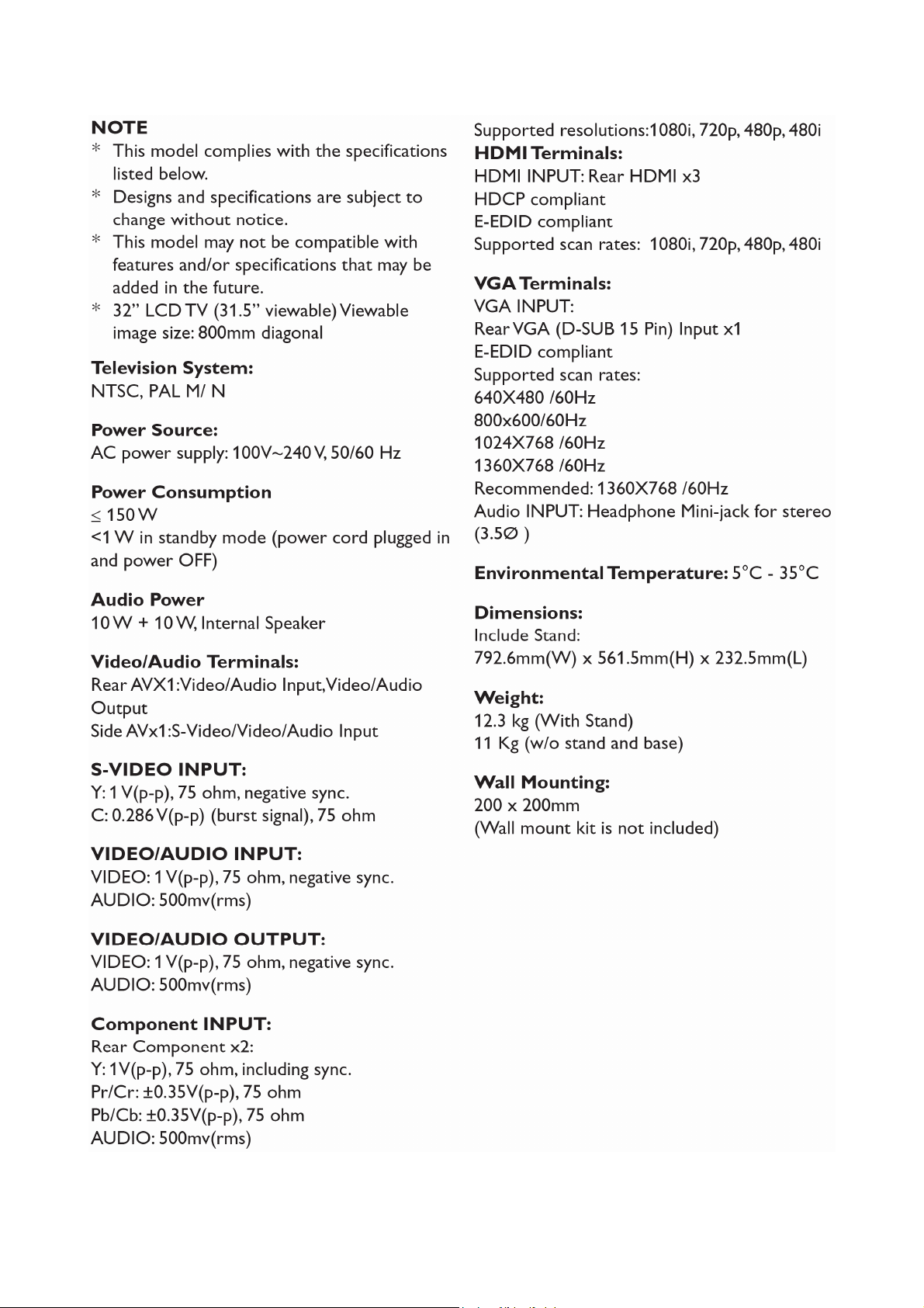
1. General Specification
4
Page 5
2. Operating Instructions
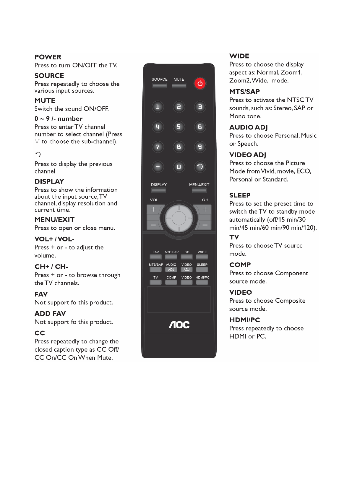
2.1 The Use of Remote Control
5
Page 6
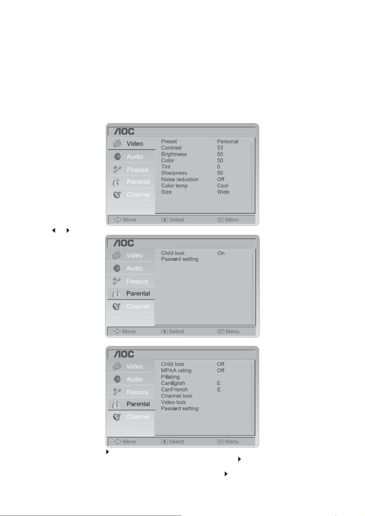
2.2 To Use the Menus
1. Press the MENU/EXIT button to display or close the main menu.
2. Use the Navigation Ring to move around to select, adjust or confirm an item in the OSD (On Screen Display)
menu.
Press the MENU/EXIT button to enter the main OSD. Adjust the items including Video menu, Audio menu,
Feature menu, Parental menu, Channel menu and VGA menu. However, some function items in the menus may
only be enabled in the particular source modes.
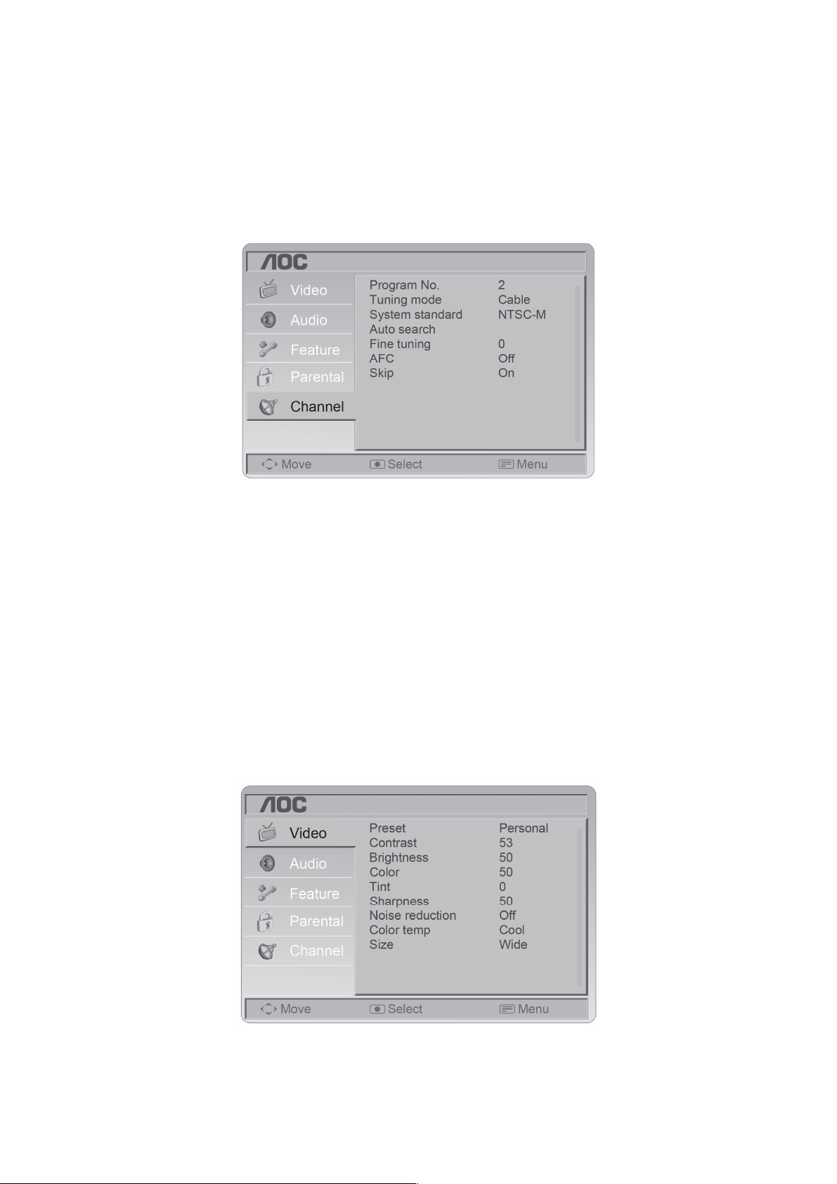
Channel Menu
The Channel menu in TV mode shows as below.
1. Program No.: Shows the current channel number.
2. Tuning mode: Select the mode of TV signal as Cable or Air.
3. System standard: Can set as NTSC-M, Auto, PAL-M or PAL-N. Advise please do not change this item after auto
search action.
4. Auto search: Select "Auto Search" to search all signaled channel; when the searching is complete, it stays at the
first channel with signal and all channels that have been located are stored. If you would like to stop "Auto Search"
during the process, simply by pressing the MENU/EXIT button.
5. Fine tuning: Fine tune the frequency of current channel.
6. AFC: AFC can be set to ON or OFF. Set to ON, the TV will search signal automatically; when there is any offset in
the signal, will automatically adjust the channel to the correct frequency.
7. Skip: Skip can be set to ON or OFF. When it is set to ON, a channel can be skipped by pressing the switching
button on the remote control or on the front panel.
VIDEO MENU
The Video menu in most source modes shows as below. It provides several video adjustment items for user fine
tuning the video display. Only in VGA source mode, the Video menu simply provides Preset, Contrast, Brightness,
Color Temp and Size items.
1. Preset: Designed for different types of video mode. Can select Personal, Standard, Vivid, Movie and ECO mode.
2. Contrast: Video contrast adjustment, can adjust only when Preset is setted as Personal. The tuning range is 0 ~
100.
3. Brightness: Video brightness adjustment, can adjust only when Preset is setted as Personal.The tuning range is
0 ~ 100.
6
Page 7
4. Color: Video color chroma adjustment, can adjust only when Preset is setted as Personal. The tuning range is 0 ~
100. (Not support in HIDMI source mode.)
5. Tint: Video tint adjustment, Can only select with NTSC signal.the tuning range is -50 ~ +50. (Not support in
YPbPr and HIDMI source mode.)
6. Sharpness: Video sharpness adjustment, the tuning range is 0 ~ 100.
(Not support in HIDMI source mode.)
7. Noise reduction: Designed for different noise reduce effect, user can select off, Low, Normal and High.
8. Color temp: There are three options of colour temperature provided for users - warm, normal and cool.
9. Size: There are various functions provided for zoom in or zoom out. Can select Normal, Zoom1, Zoom2 and
Wide.
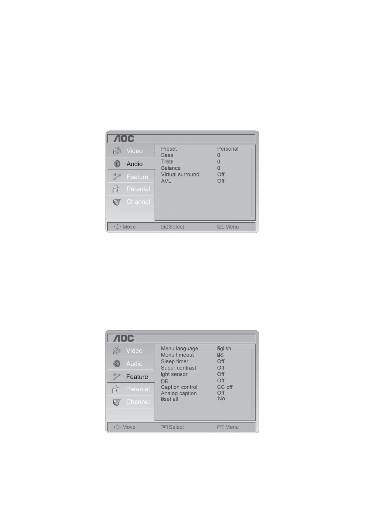
AUDIO MENU
The Audio menu in TV mode shows as below. It provides audio adjustment for user to modify the audio setting.
1. Preset: Designed for different types of sound mode. Can select Personal, Music and Speech.
2. Bass: Bass tone adjustment, can adjust only when Preset is setted as Personal.The tuning range is -10 ~10.
3. Treble: Treble tone adjustment, can adjust only when Preset is setted as Personal. The tuning range is -10~10.
4. Balance: Audio balance adjustment, the tuning range is -10~10.
5. Virtual Surround: It can create the perception that there are many more sources of sound than are actually
present.
6. AVL:Choose On or off to adjust volume to be consistent across programs and channels automatically.
FEATURE MENU
The Feature menu in TV mode shows as below. This menu gives users the most flexibilities to satisfy their generally
demands. According to the various requirements in different source modes, certain features should be hidden
(disable) on the menu. The details footnotes will be described clearly below.
1. Menu language: There are four language options provided - English, French, Spanish and Portuguese.
2. Menu timeout: Adjust the time of menu display.
3. Sleep timer: Function with which you can set a time period after which the TV should turn itself off. You can set it
as off, 15m, 30m, 45m, 60m, 90m, 120m.
4. Super contrast: Enhances the contrast of the color saturation. You can select On (default) or Off.
5. Light sensor: You can select On or Off(default).
6. DCR: dynamic contrast.
7
Page 8
7. Caption control: Select CC channel as On, CC on, when mute or Off.
8. Analog Caption: Select analog caption as CC1, CC2, CC3, CC4, TT1, TT2, TT3, TT4, Off.
9. Reset all: Reset all OSD setting to default value.
PARENTAL MENU
Parental Control: provide the parental Control (V-chip) function setting. Before entering the Parental Control
sub-menu, user has to key in the password first. Enter the Child Lock item, then the user can modify the restricted
table about MPAA or TV Rating respectively. While exiting the sub-menu, the parental control function is working.
(The default password is: 0 0 0 0.)
Setting the Parental Control level
To set the Parental Control level:
1. Press MENU. The on-screen menu opens with Picture highlighted.
2. Press
3. Press ENTER, enter the password (default password is 0000), then press ▼ or ▲ to highlight Password setting.
or to select System, then press ▲ or ▼ to highlight Parental Control.
4. Press ENTER, then press
5. To set the MPAA rating, press ▼ or ▲ to highlight MPAA rating, then press
The rating you locked and all higher ratings will be locked. You can select G, PG, PG-13, R, NC-17, X or Off.
6. To set the PG rating, press ▼ or ▲ to highlight PG rating, then press
The PG rating screen opens.
to set Child lock to Off.
to select the rating you want to lock.
.
8
Page 9
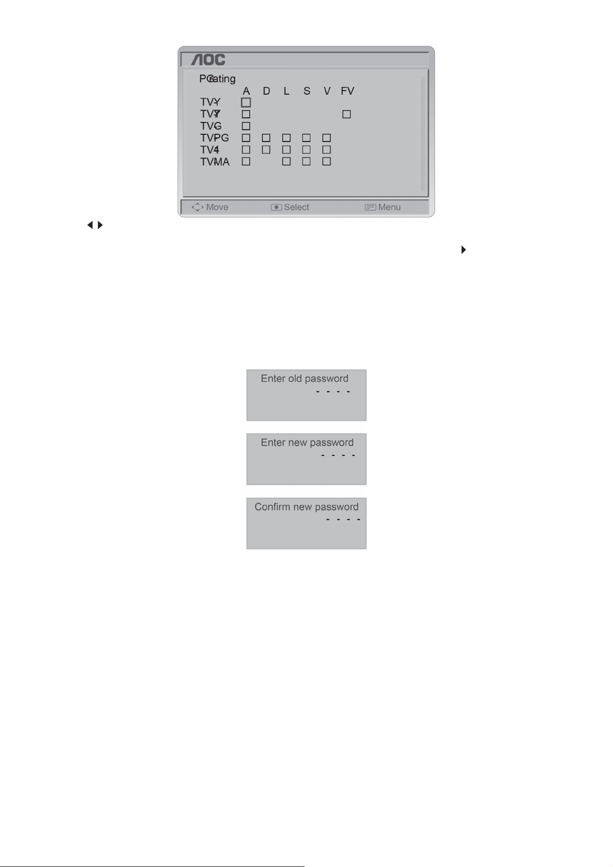
7. Press
higher ratings will be locked.
8. To set the Canadian English rating, press ▼or ▲ to highlight Can. Englishor, then press
you want to lock. The rating you locked and all higher ratings will be locked. You can select E, C, C8+, G, PG, 14+,
or 18+.
9. To set the Canadian French rating, press ▼or ▲ to highlight Can. French, then press to select the rating you want
to lock. The rating you locked and all higher ratings will be locked. You can select E, G, 8+, 13+, 16+, or 18+.
10. Channel Lock: Select channel lock or not. 11. Video Lock: Select source lock or not. 12. Press MENU/EXIT to
close the menu.
Password Set: Change the 4-numeral parental control password. Three steps are required for changing the
password: Enter Old Password -> Enter New Password -> Confirm New Password. Note: This item is only available
in TV, Composite and S-Video source modes. The default password is 『0 0 0 0』.
▼or ▲ to select a rating, then press ENTER to lock or unlock the rating. The rating you locked and all
to select the rating
VGA MENU
This option only shows and is available in VGA mode, which provides several items for the VGA display fine tuning.
1. Auto Adjust: Adjust the settings automatically.
2. H-Position: Adjust the horizontal position of the picture. (0-100)
3. V-Position: Adjust the vertical position of the picture. (0-100)
4. Clock: Adjust picture clock to reduce Vertical-Line noise. (0-100)
5. Phase: Adjust Picture Phase to reduce Horizontal-Line noise. (0-100)
9
Page 10
2.3 How to Connect
Connecting Equipment
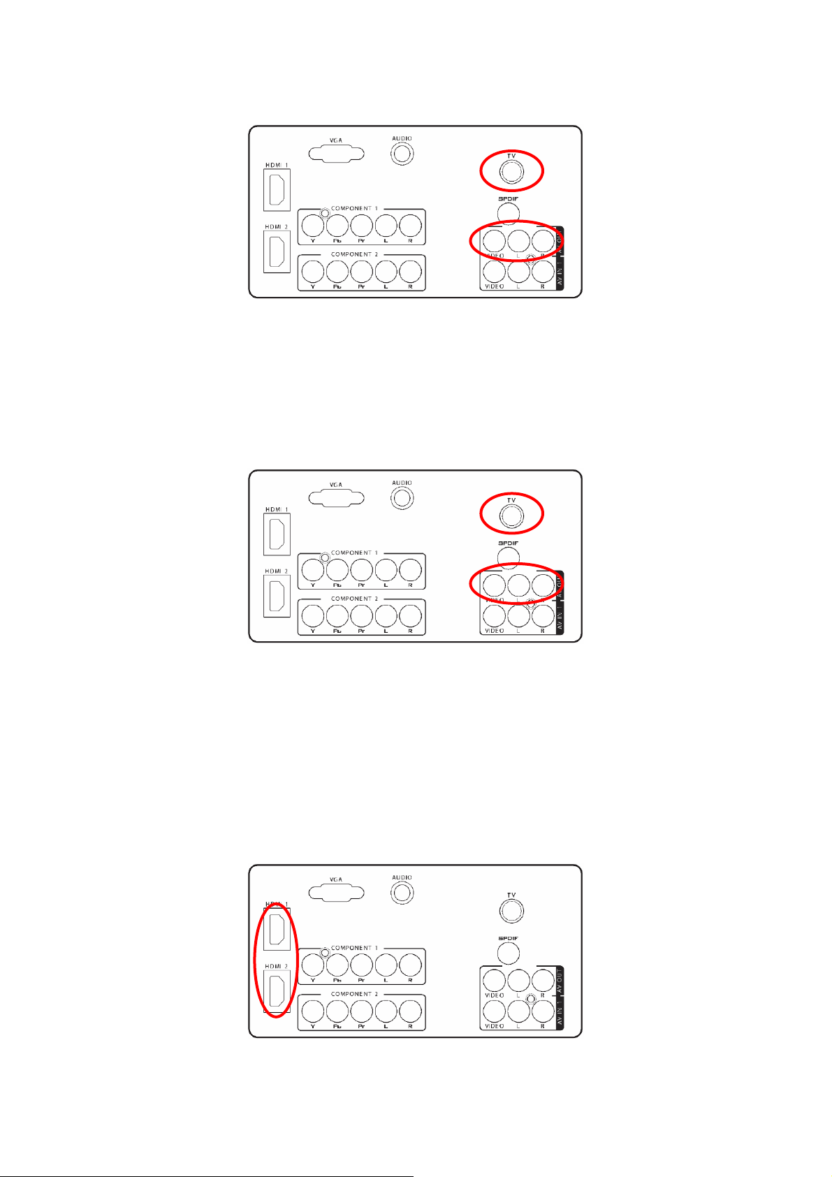
Using Your Antenna or Cable for TV
1. Turn off the TV.
2. Connect the coaxial (RF) connector from your antenna or cable (out-of-the-wall, not from the Cable Box) to the
ANTENNA connector at the rear of the TV.
3. Turn on the TV.
4. Select TV using the SOURCE button on the Remote control or the INPUT keypad on the side of the TV, or
pressing the TV button on the Remote Control.
5. Connect the AV OUT and AV IN of the other TV,the signal will display on the other TV.
Using the Antenna or Cable for your VCR
1. Turn off the TV.
2. Connect the “Output to TV”, “RF Out” or “Antenna Out” connector on the rear of your VCR to the ANTENNA
connector at the rear of the TV.
3. Turn on the TV.
4. Select TV using the SOURCE button on the Remote control or the INPUT keypad on the side of the TV or directly
by pressing the TV button on the Remote Control.
5. Connect the AV OUT and AV IN of the other TV,the signal will display on the other TV.
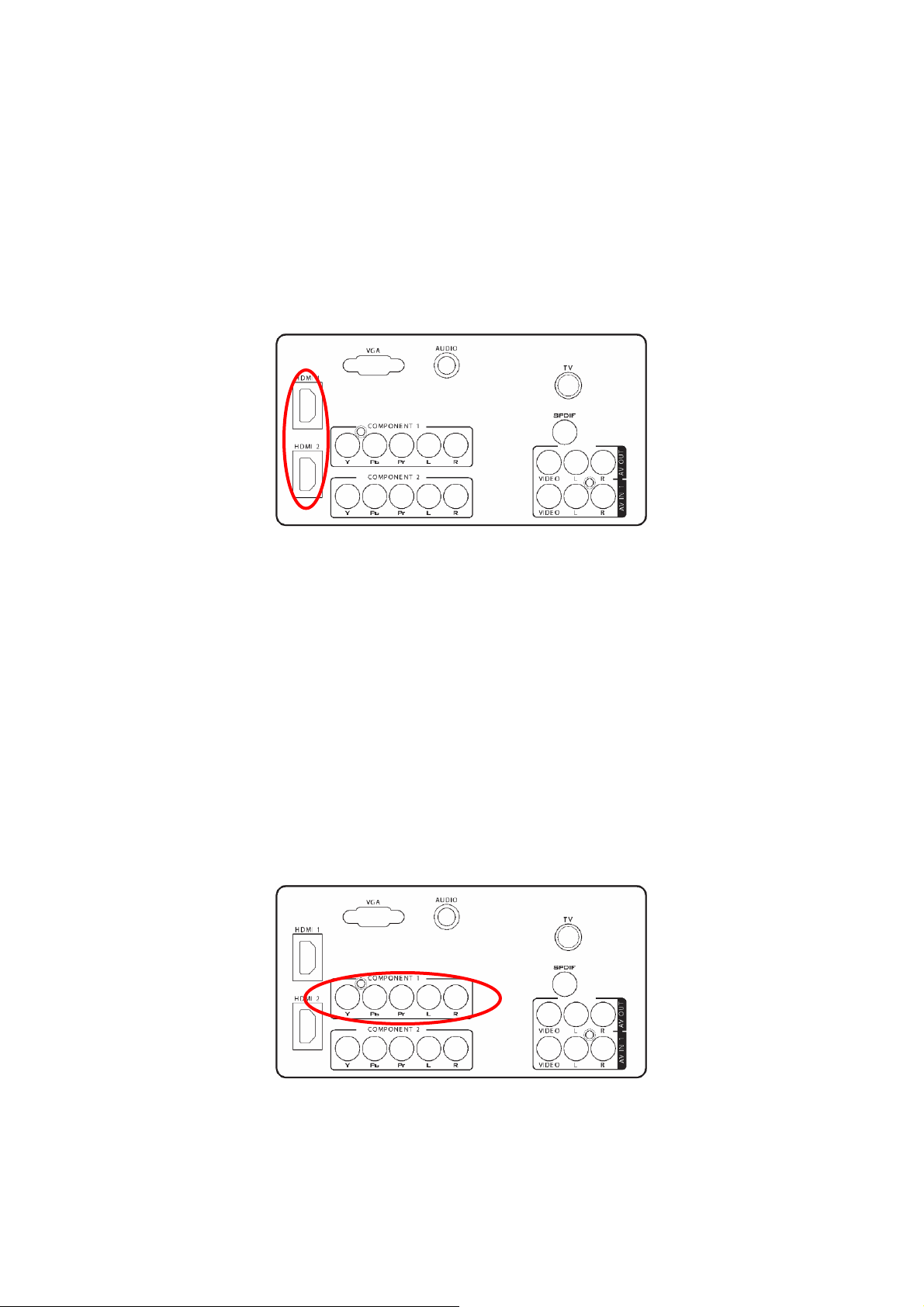
Connecting Your TV Set-Top Box
Using HDMI
TV Set-Top Boxes that have a HDMI digital interface should be connected to the HDMI input of the LCD TV for
optimal results.
10
Page 11
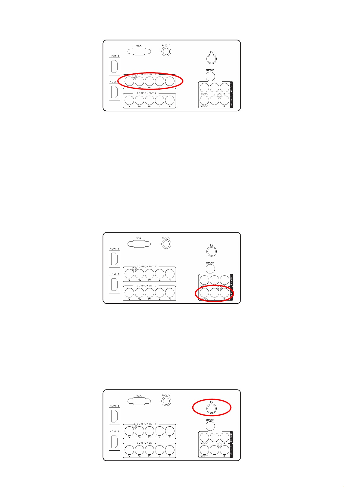
Using Component Video
Connecting your TV Set-Top Box (Better):
1. Turn off the TV and TV Set-Top Box.
2. Connect the Pr (red color) connector on your TV Set-Top Box to the corresponding Pr (red color) connector in the
Component group.
3. Connect the Pb (blue color) connector on your TV Set-Top Box to the corresponding Pb (blue color) connector in
the Component group.
4. Connect the Y (green color) connector on your TV Set-Top Box to the corresponding Y (green color) connector in
the Component group.
5. Using an audio cable (red and white connectors), connect the cable to the audio output connectors associated
with the Component output on your TV Set-Top Box and connect the other end to the audio connectors associated
with the Component.
6. Turn on the TV and TV Set-Top Box.
7. Select YPbPr using the SOURCE button on the Remote control or the INPUT keypad on the side of the TV or
directly by pressing the COMP button on the Remote Control.
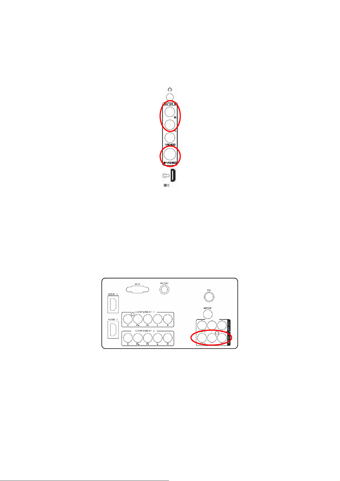
Connecting Your Basic Set-Top Box
Using Composite Video
1. Turn off the TV and Set-Top Box.
2. Using an AV Cable, connect the Video (yellow color) connector on your Set-Top Box to the corresponding Video
(yellow color) connector in the AV group at the rear of the TV.
3. Using the red and white connectors, connect the cable to the audio output connectors associated with the Video
output on your Set-Top Box and connect the other end to the audio connectors associated with the AV input at the
rear of the TV.
4. Turn on the TV and Set-Top Box.
5. Select AV-1 using the SOURCE button on the Remote control or the INPUT keypad on the side of the TV or
directly by pressing the VIDEO button on the Remote Control.
Using Coax (RF)
11
Page 12
1. Turn off the TV.
2. Using a Coax (RF) cable, connect one end to the TV .
3. Turn on the TV.
4. Select TV using the SOURCE button on the Remote control or the INPUT keypad on the side of the TV or directly
by pressing the TV button on the Remote Control.
Connecting Your DVD Player
Using HDMI
DVD players that have a digital interface such as HDMI (High Definition Multimedia Interface) should be connected
to the HDMI input of the LCD TV for optimal results.
Connecting your DVD Player (Best)
1. Turn off the TV and DVD player.
2. Connect a HDMI cable to the HDMI output of your DVD player and the other end to the HDMI Input at the rear of
the TV.
3. Turn on the TV and DVD player.
4. Select HDMI using the SOURCE button on the Remote control or the INPUT keypad on the side of the TV or
directly by pressing the HDMI/PC button on the Remote Control.
For DVD Players with DVI:
1. Turn off the TV and DVD player.
2. Using a HDMI-DVI cable, connect the DVI end to your DVD player and the HDMI end to the HDMI Input at the
rear of the TV.
3. Turn on the TV and your DVD player.
4. Select HDMI using the SOURCE button on the Remote control or the INPUT keypad on the side of the TV, or
directly by pressing the HDMI/PC button on the Remote.
Using Component Video
Connecting your DVD Player (Better)
1. Turn off the TV and DVD player.
2. Connect the Pr (red color) connector on your DVD player to the corresponding Pr (red color) connector in the
Component at the rear of the TV.
3. Connect the Pb (blue color) connector on your DVD player to the corresponding Pb (blue color) connector in the
Component group at the rear of the TV.
4. Connect the Y (green color) connector on your DVD player to the corresponding Y (green color) connector in the
Component group at the rear of the TV.
5. Using an audio cable (red and white connectors), connect the cable to the audio output connectors associated
12
Page 13
with the Component output on your DVD player and connect the other end to the audio connectors associated with
the Component input at the rear of the TV.
6. Turn on the TV and DVD player.
7. Select Component using the SOURCE button on the Remote control or the INPUT keypad on the side of the TV
or directly by pressing the COMP button on the Remote Control.
Using S-Video (AV-2)
Connecting your DVD Player (Good):
1. Turn off the TV and DVD player.
2. Connect the S-Video jack on the rear of your DVD player to the S-Video jack in the AV group on the rear of the
TV.
3. Connect an audio cable (white and red connectors) to the audio output connectors associated with the S-Video
output on your DVD player and connect the other end to the audio connectors associated with the AV input on the
rear of the TV.
4. Turn on the TV and DVD player.
5. Select AV-2 using the SOURCE button on the Remote control or the INPUT keypad on the side of the TV, or
directly by pressing the VIDEO button on the Remote Control.
Using Composite (AV) Video
Connecting your DVD Player (Good)
1. Turn off the TV and DVD player.
2. Connect the Video (yellow color) connector on your DVD player to the Video (yellow color) connector in the AV
group.
3. Connect the R (red color) and L (white color) audio connectors on your DVD player to the corresponding R (red
color) and L (white color) audio input connectors in the AV group.
4. Turn on the TV and DVD Player.
5. Select AV using the SOURCE button on the Remote control or the INPUT keypad on the side of the TV or directly
by pressing the VIDEO button on the Remote Control.
13
Page 14
Connecting Your VCR or Video Camera
1. Turn off the TV and VCR or Video Camera.
2. Connect the S-Video jack on the rear of your VCR or Video Camera to the S-Video jack in the AV group on the
rear of the TV.
3. Connect an audio cable (white and red connectors) cable to the audio output connectors associated with the
S-Video output on your VCR or Video Camera and connect the other end to the audio connectors associated with
the AV input on the rear of the TV.
4. Turn on the TV and VCR or Video Camera.
5. Select AV-2 using the SOURCE button on the Remote control or the INPUT keypad on the side of the TV or
directly by pressing the VIDEO button on the Remote Control.
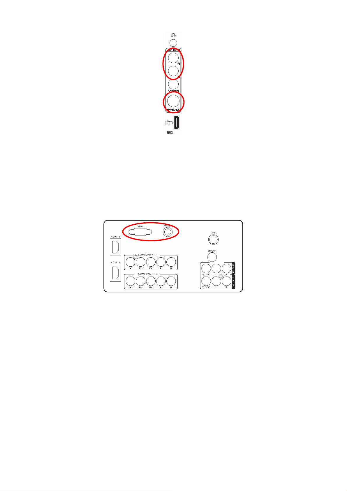
Connecting to a PC
1. Turn off the TV and PC.
2. Connect a 15-pin D-Sub RGB (VGA) cable to the RGB output of your PC and the other end to the VGA input at
the rear of the TV.
3. Connect the Audio Out on your computer to the AUDIO input at the rear of the TV.
4. Turn on the TV and PC.
5. Select VGA using the SOURCE button on the Remote control or the INPUT keypad on the side of the TV or
directly by pressing the HDMI/PC button on the Remote.
14
Page 15
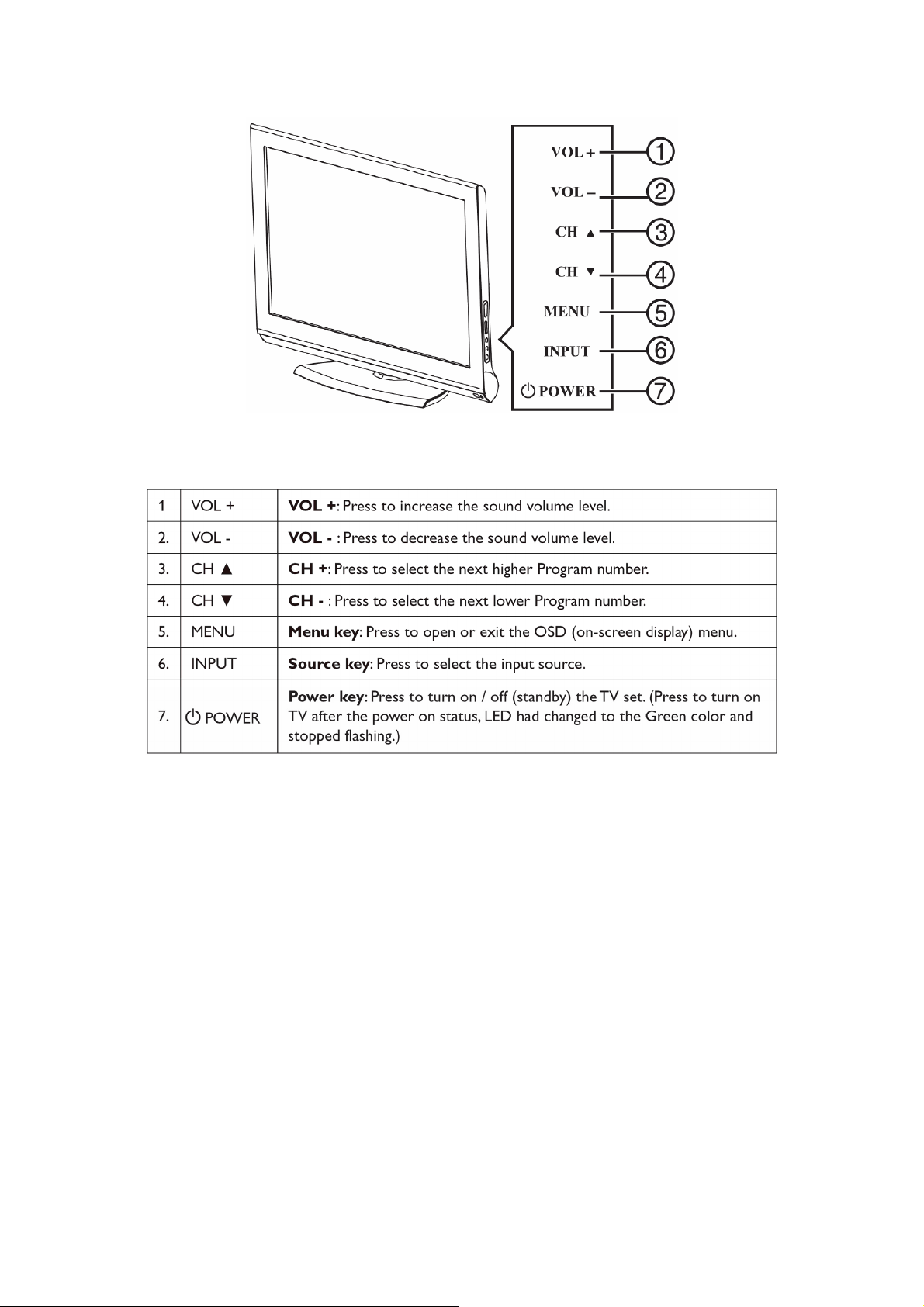
2.4 Front Panel Control Knobs
15
Page 16
3. Input/Output Specification
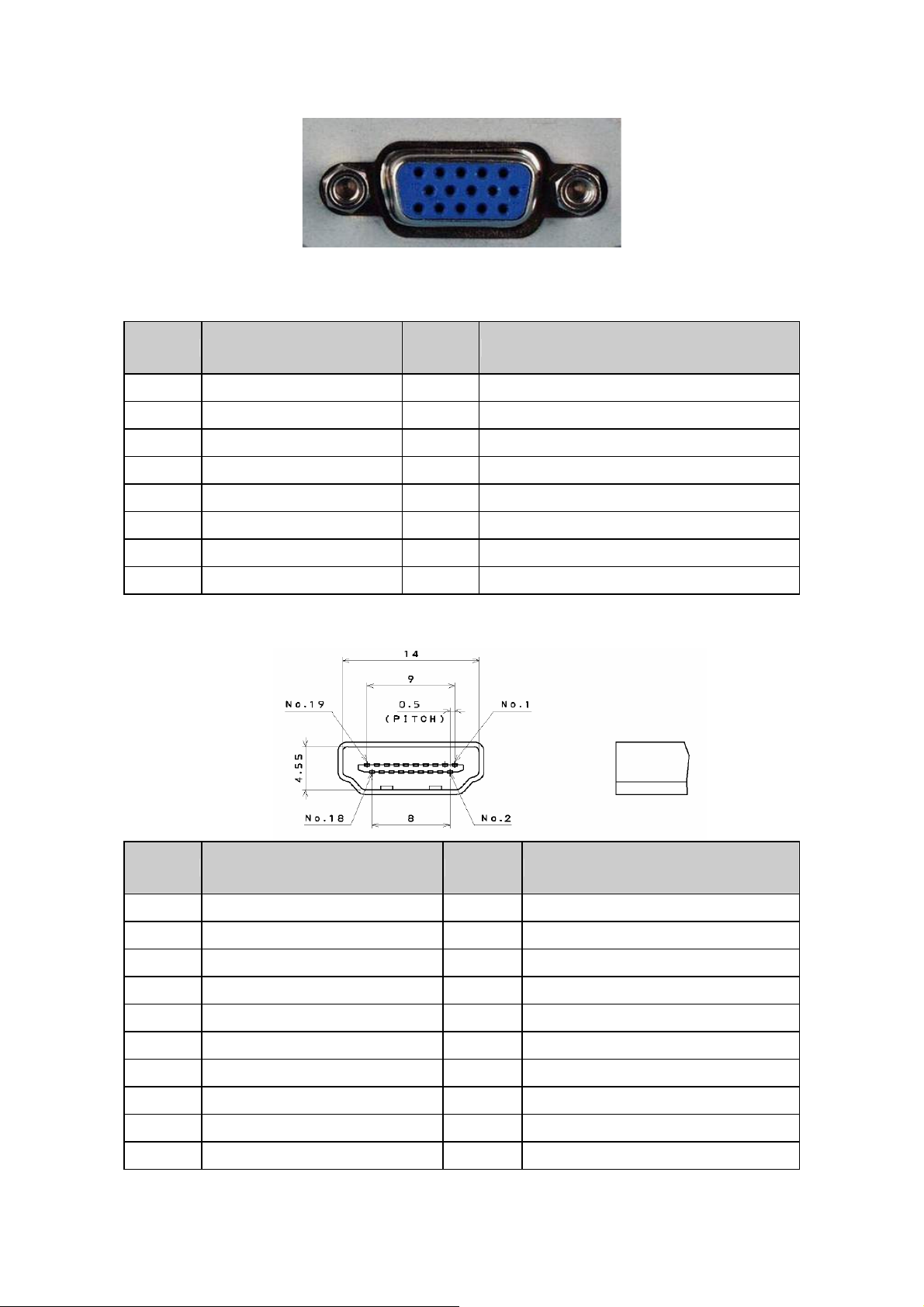
3.1 RGB Signal Input
15 - Pin Color Display Signal Cable
Pin No. Description Pin No. Description
1 Red Video 9 5V
2 Green Video 10 Sync Ground
3 Blue Video 11 Not Used
4 Not Used 12 Serial Data for DDC
5 Ground 13 H-Sync.
6 Red Video Ground 14 V-Sync.
7 Green Video Ground 15 Serial Clock for DDC
8 Blue Video Ground
3.2 HDMI Digital Connector Pin Assignments
Pin No. Description Pin No. Description
1 TMDS Data2+ 2 TMDS Data2 Shield
3 TMDS Data2- 4 TMDS Data1+
5 TMDS Data1 Shield 6 TMDS Data1-
7 TMDS Data0+ 8 TMDS Data0 Shield
9 TMDS Data0- 10 TMDS Clock+
11 TMDS Clock Shield 12 TMDS Clock-
13 CEC 14 Reserved (N.C. on Device)
15 SCL 16 SDA
17 DDC/CEC Ground 18 +5V Power
19 Hot Plug Detect
16
Page 17
3.3 AV/S-Video/Component Video Inputs
AV (Composite Video Input)
Video1
Amplitude 1.0 Vpp (including sync)
Impedance 75 ohm terminated
S-Video (Y / C Input)
S-Video2
Video System NTSC/PAL
Y signal amplitude 1.0Vpp (including sync)
C signal amplitude 0.286Vpp
Impedance 75 ohm terminated
Component (Y, Pb/Cb, Pr/Cr Input)
Video3
DTV 480i, 480p, 720p, 1080i
Y signal amplitude 1.0Vpp (including sync )
Impedance 75 ohm terminated
Video System NTSC/PAL
Video system NTSC/PAL
Pr,(R-Y) / Pb,(B-Y) signal
amplitude
0.7Vpp
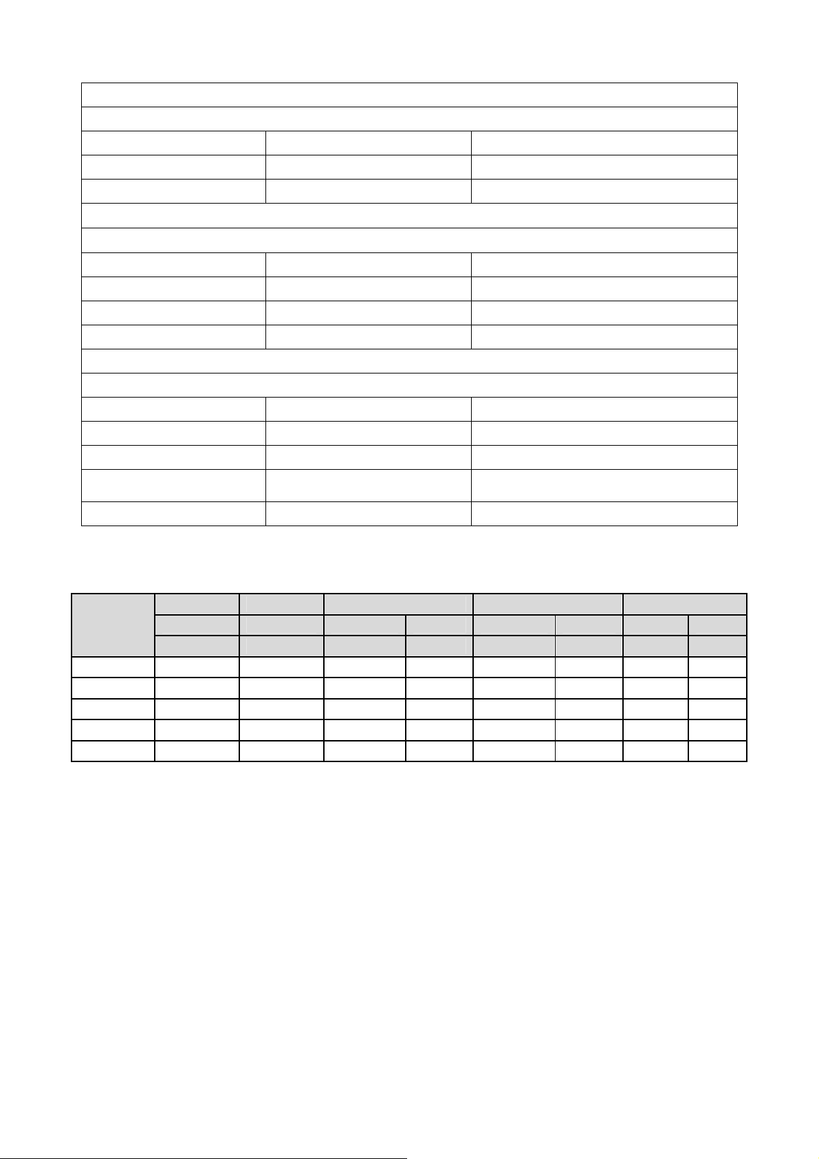
3.4 Compatible Mode Table
Dots ×
Lines
720 × 400
640 × 480
800 x 600
1024 x 768
1360 x 768
Vertical Horizontal Sync Polarity Presence Screen Mode
Frequency Frequency Horizontal Vertical Horizontal Vertical Normal Full
(Hz) (KHz) (4:3) (16:9)
70.1 31.5 NEG POS YES YES YES YES
59.9 31.5 NEG NEG YES YES YES YES
60 37.9 POS POS YES YES YES YES
60 48.363 NEG NEG YES YES YES YES
59.79 47.72 NEG POS YES YES YES YES
17
Page 18
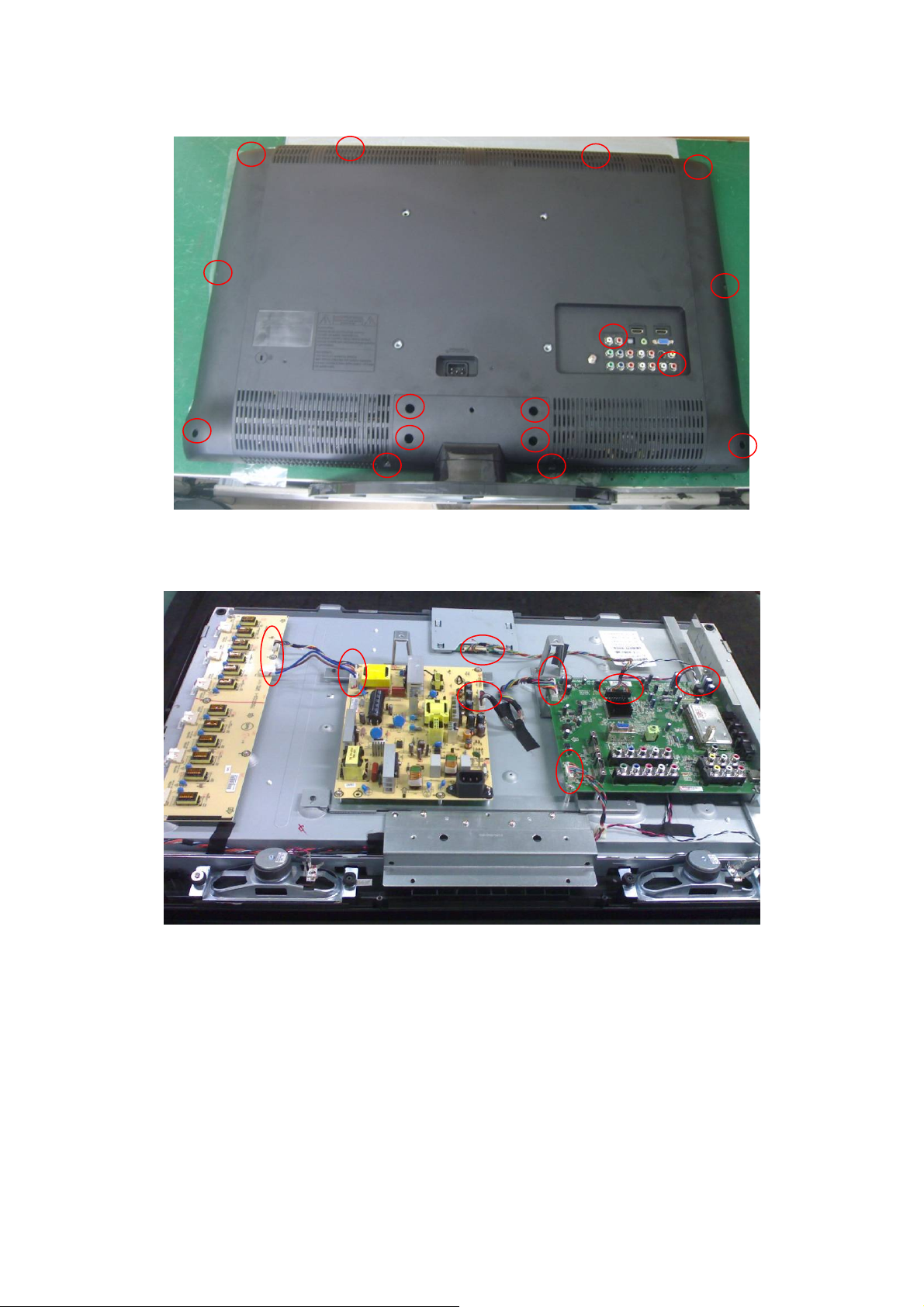
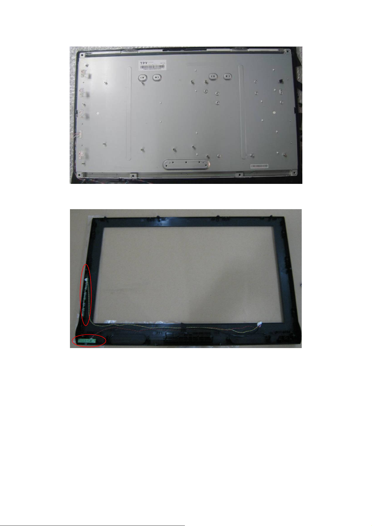
4. Mechanical Instructions
1. Remove the screws to remove the stand base and rear cover.
2. Release connectors.
18
Page 19
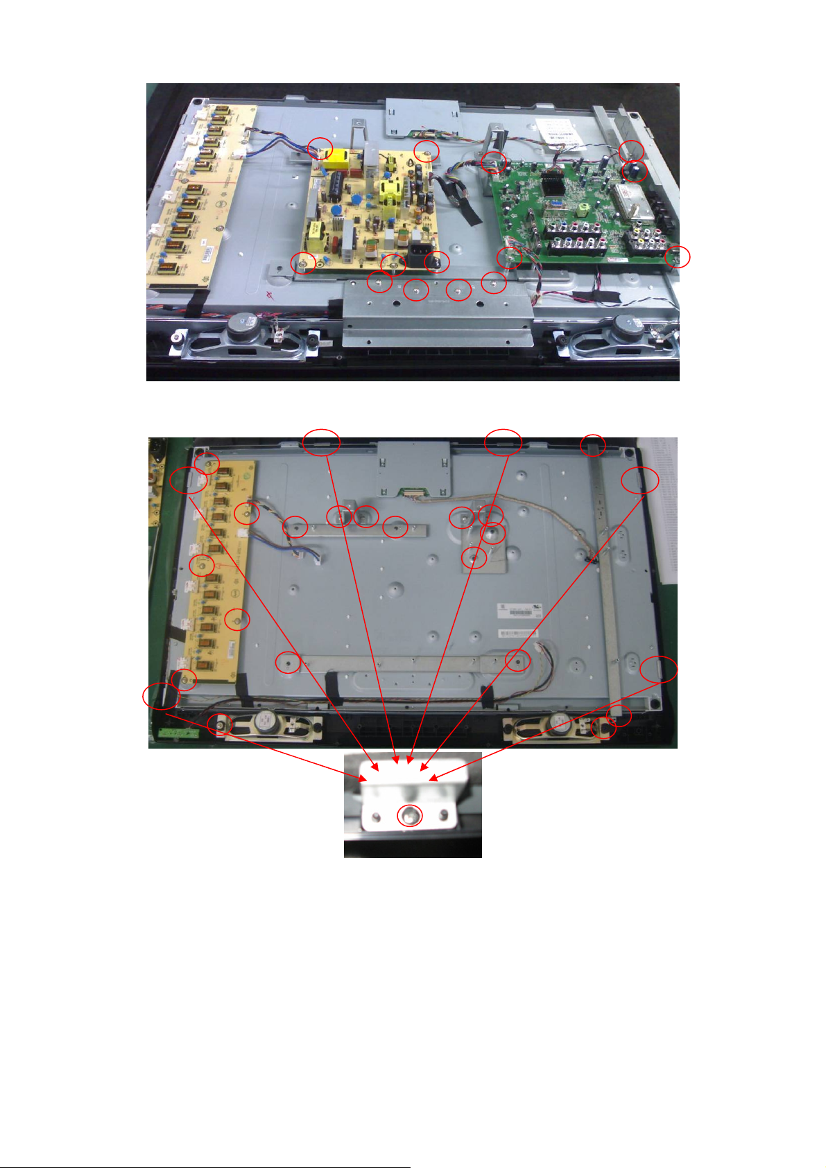
3. Remove the screws to remove main board, power board and bracket.
4. Remove the screws to remove speaker, inverter board and bracket.
19
Page 20
5. Remove the panel.
6. Remove key board and IR board.
20
Page 21
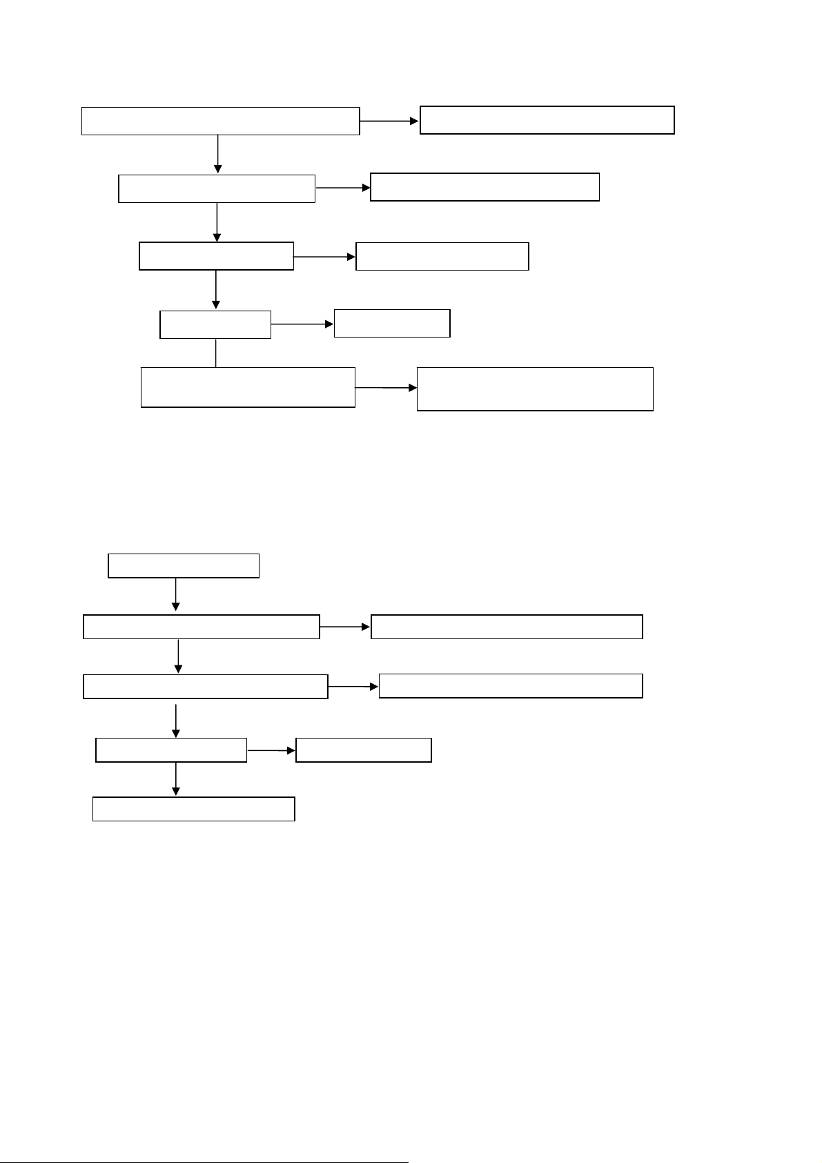
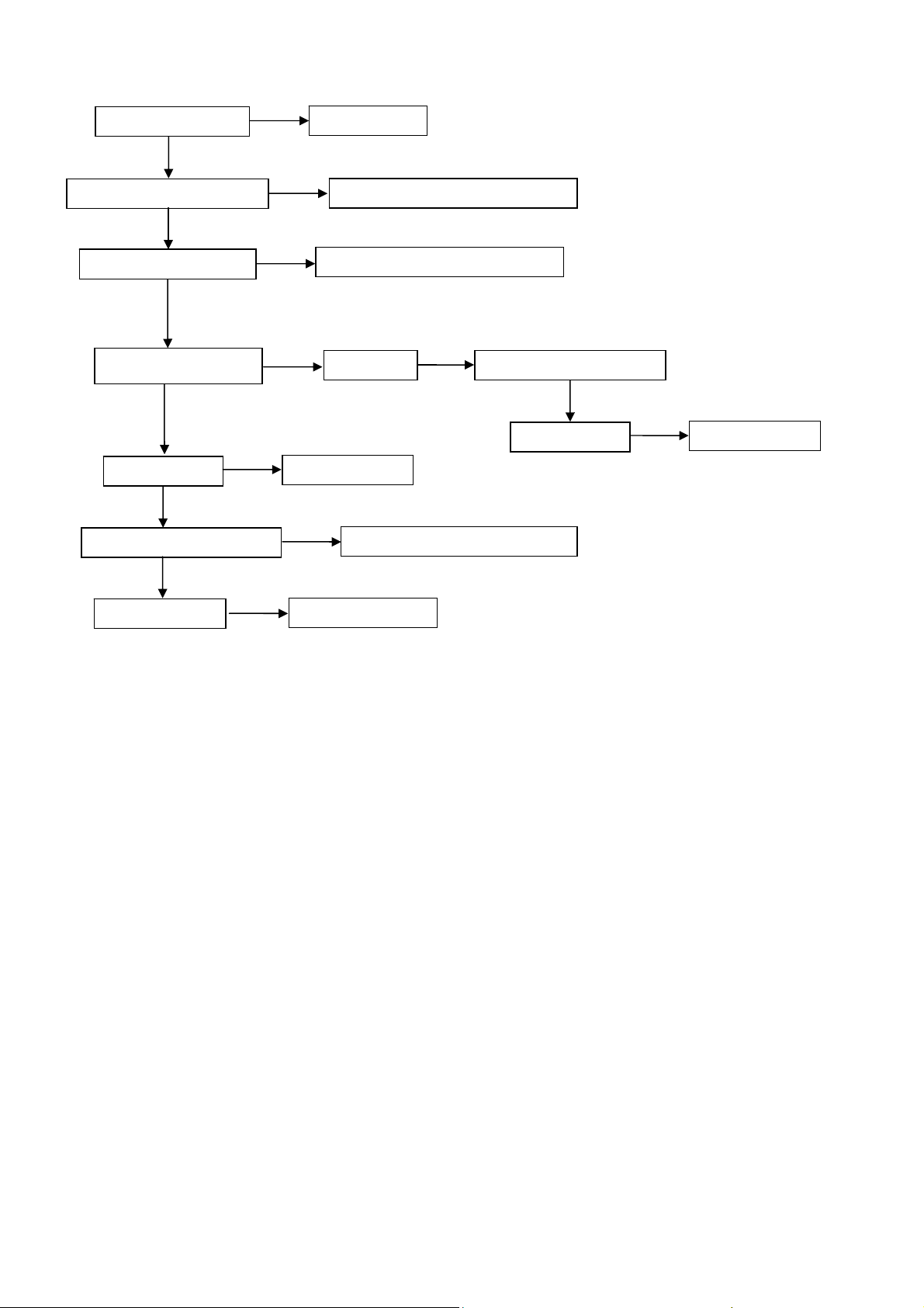
5. Repair Flow Chart
1. No Power (No LED Indicator)
Check power cord and board interface
OK
NG
Plug in power cord and interface
Check F901, BD901, C920
OK
Check D931, D932
OK
Check T901
OK
Check D950, C953, C954
NG
NG
2. Can not Start (LED Indicator Yellow)
Can not start
NG
Replace F901 or BD901 or C920
Replace D931 or D932
Replace T901
Replace D950 or C953 or C954
OK
Check key board or remote control
OK
Check U700,U702,U703,U705,U707
OK
Check U400
OK
Check I2C communication
NG
NG
Replace U400
Repair key board or remote control
NG
Replace U700,U702,U703,U705,U707
21
Page 22
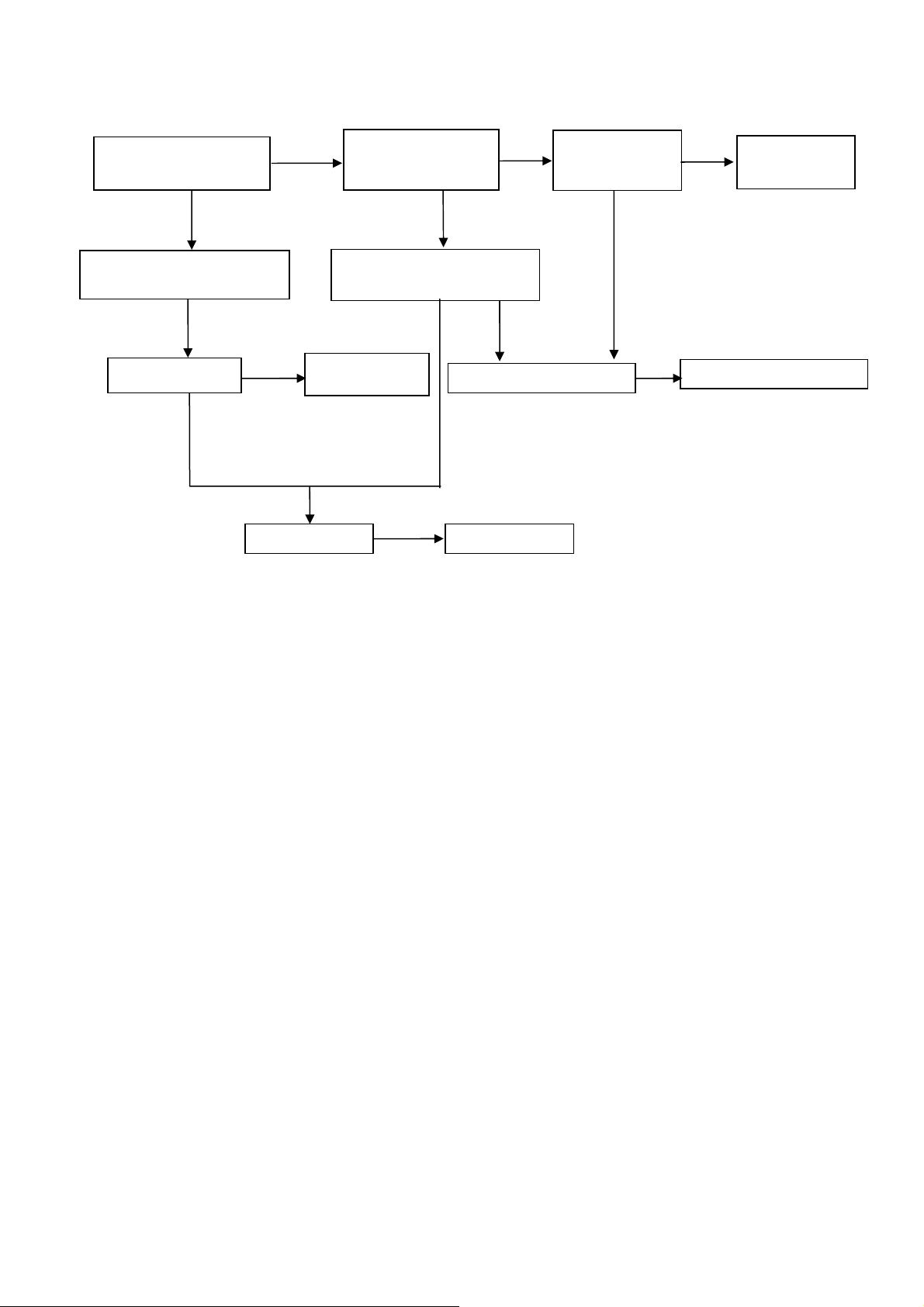
3. No Display (LED Indicator Green)
Check back light is OK
OK
Check LVDS cable
and connector
OK
Check U400
NG
NG
OK
Check Panel
Replace U400
Check 12V
power supply
OK
Check BL-ON/OFF signal
NG
Replace Panel
NG
NG
Check Q707, Q708
Check PS
signal
NG
NG
OK
Replace Q707, Q708
Check power
board
22
Page 23
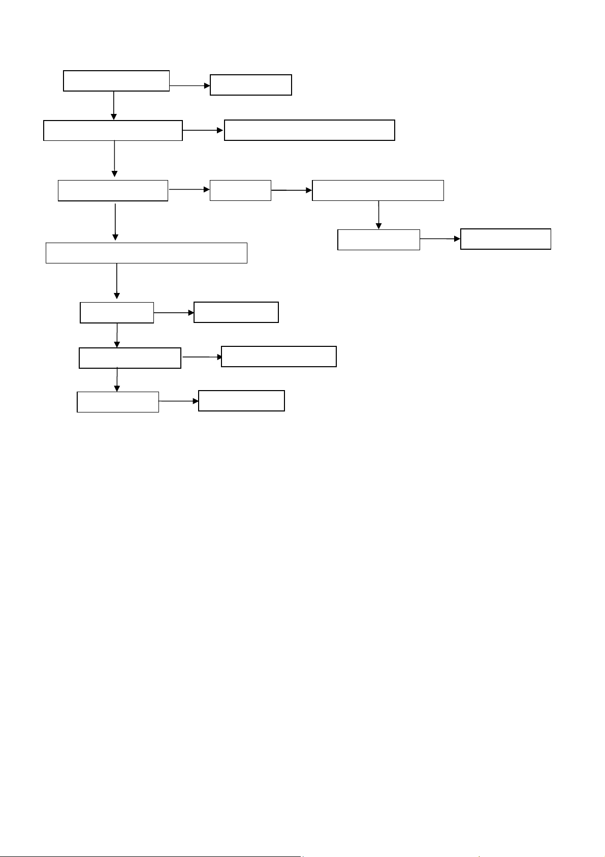
A
4. Abnormal Display
Check the source
OK
NG
Reset source
Check signal filter circuit
OK
Check input signal
V, S-video, Comp,PC,HDMI signal
OK
Check U400
OK
Check LVDS cable
OK
Check panel
NG
NG
Replace U400
NG
NG
Replace the filter or inductance
TV signal Check TV system setup
OK
Check TU100
Replace LVDS cable
Replace panel
NG
Replace TU100
23
Page 24
p
5. No Sound
Check the source
OK
Reset source
Check signal filter circuit
Check Earphone jack
OK
Check input signal
OK
Check U400
OK
Check U600, U601, U603
OK
Check speaker
NG
NG
NG
NG
Replace the Earphone jack
SIF signal Check TV system setu
Replace U400
NG
Replace speaker
Replace the filter or inductance
Check TU100
Replace U600, U601 or U603
OK
NG
Replace TU100
24
Page 25
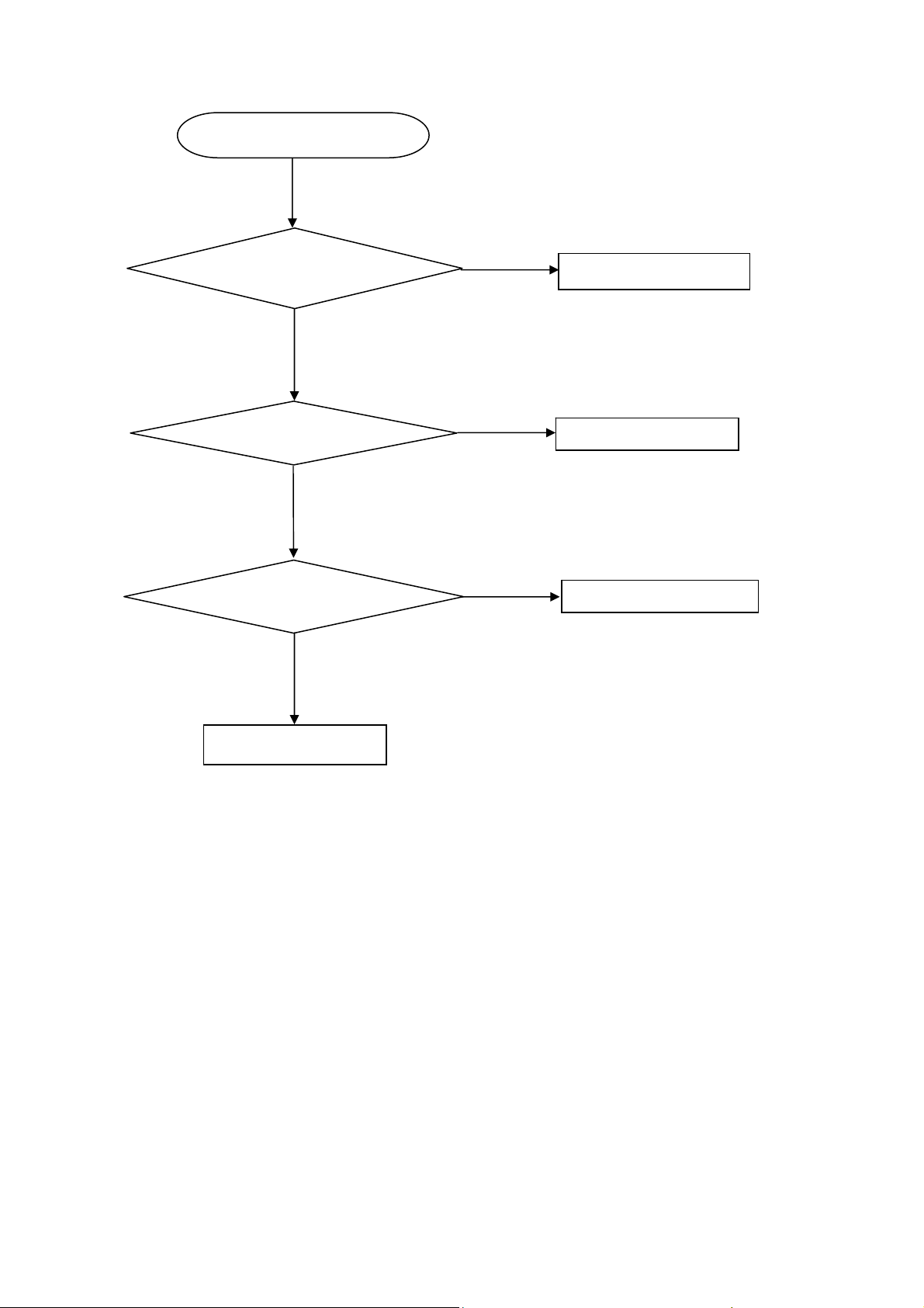
6. Key Board
OSD is unstable or not working
Is Key Pad Board connecting normally?
Y
Is Button Switch normally?
Y
Is Key Pad Board Normally?
Y
Check Main Board
N
Connect Key Pad Board
N
N
Replace Button Switch
Replace Key Pad Board
25
Page 26
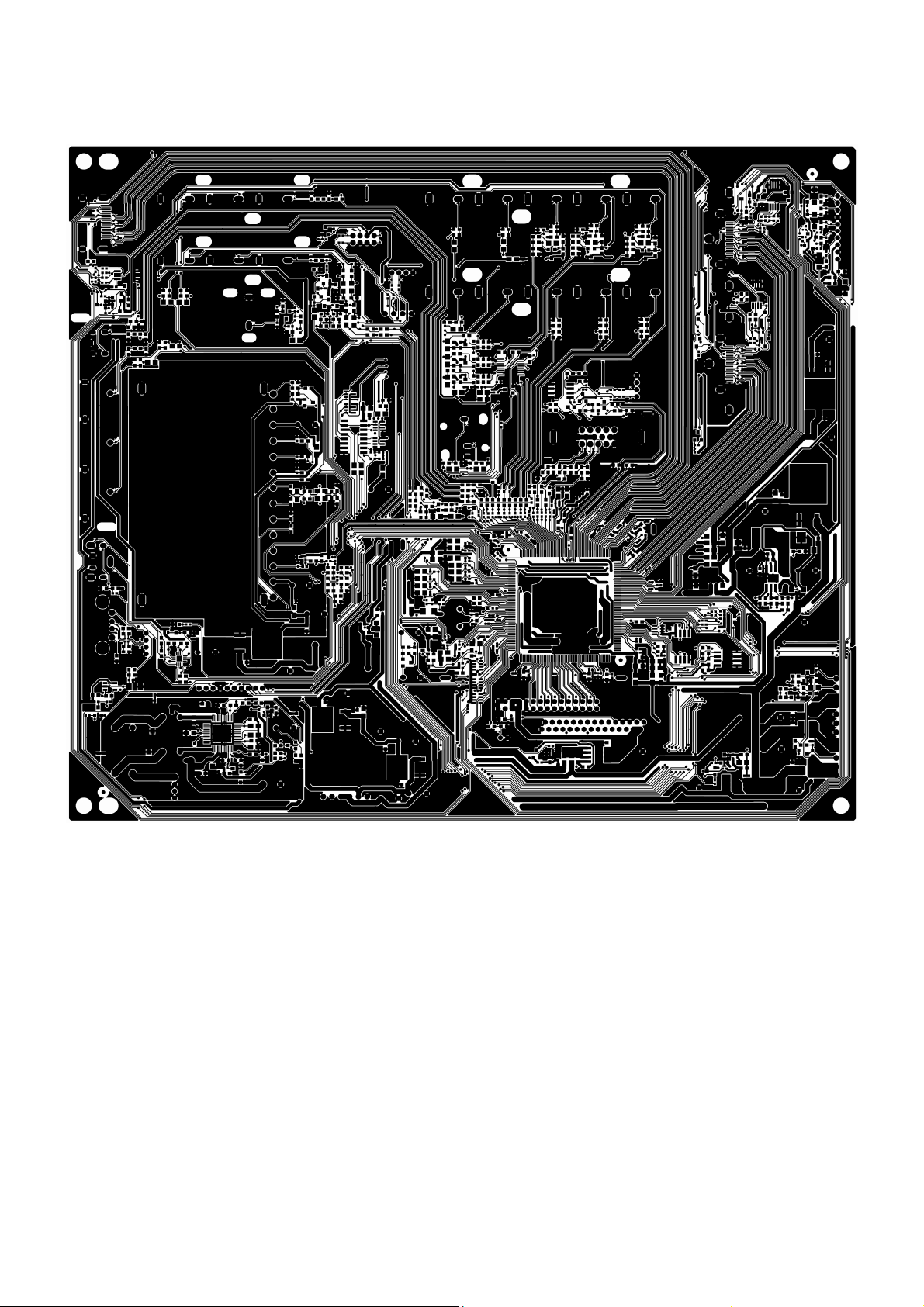
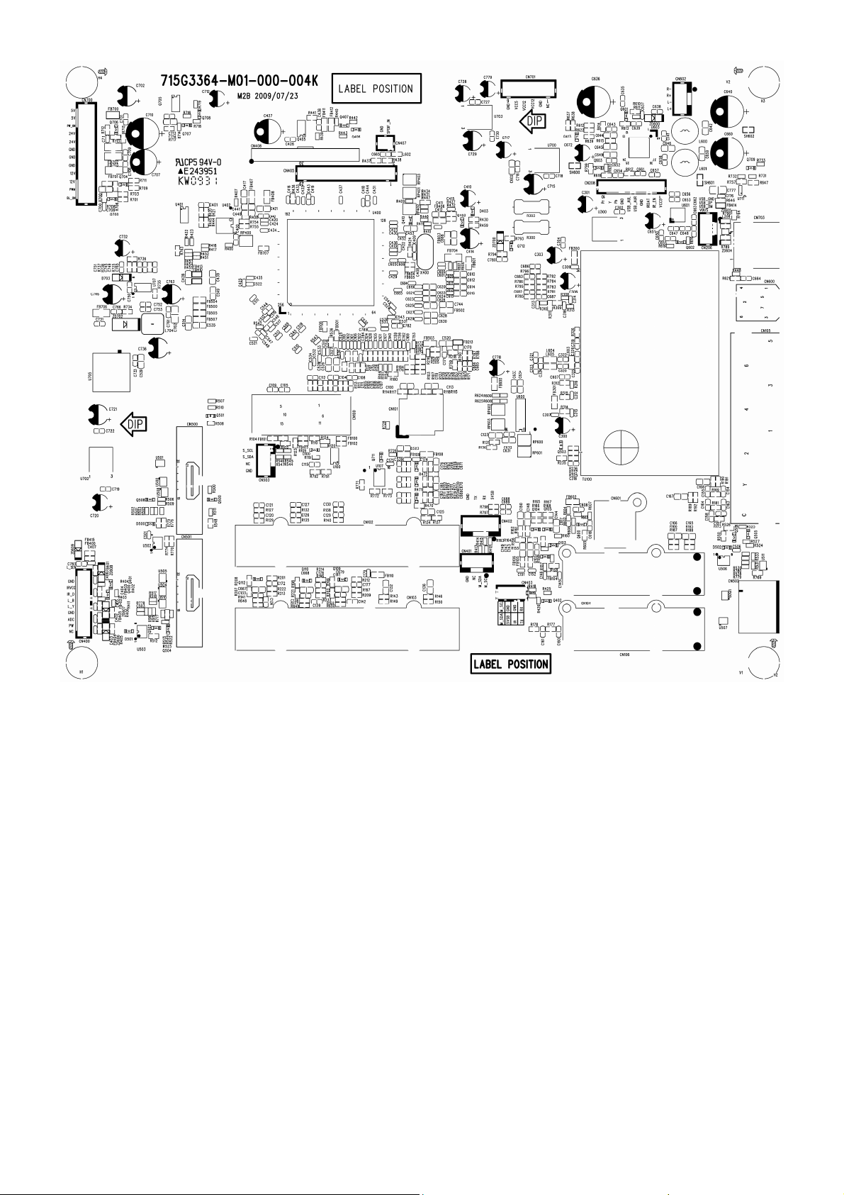
6. PCB Layout
6.1 Main Board
715G3364M01000004K
26
Page 27
27
Page 28
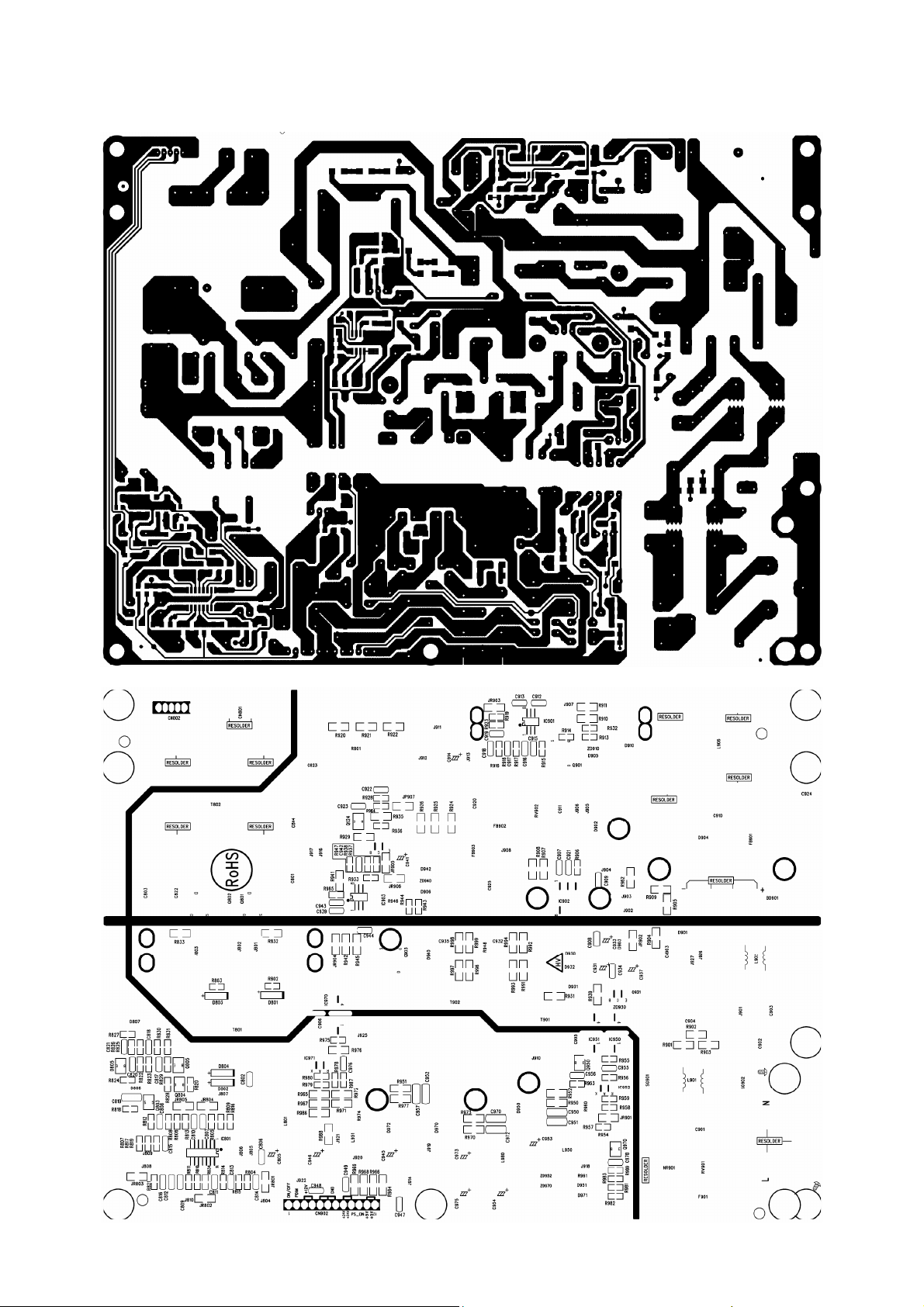
6.2 Power Board
715G3332 1
28
Page 29
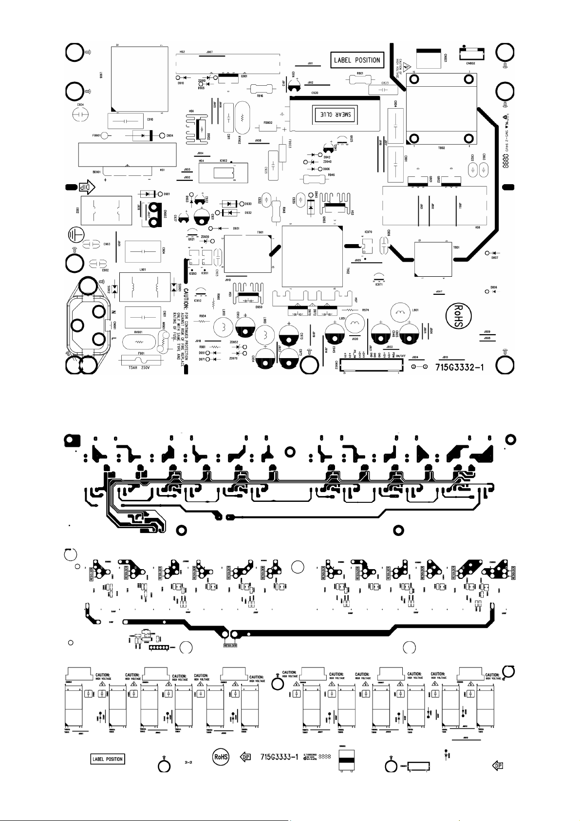
6.3 Inverter Board
715G3333 1
29
Page 30
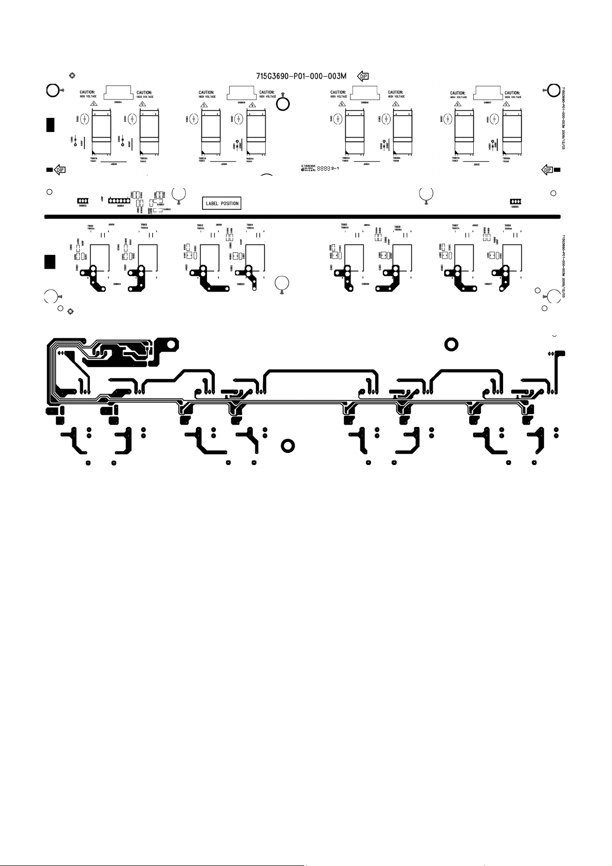
715G3690P01000003M
30
Page 31

6.4 Key Board
715G3400 1
6.5 IR Board
715G3394 2
31
Page 32

7. Adjustment
It’s no need to adjust the white balance for this model.
1. Enter into the factory mode:
Turn on the TV, press MENU key with remote control, then press number key 1 Æ 9 Æ 9 Æ 9. It will achieve the
factory mode.
2. Click on "Auto Color" in the PC and Component modes:
PC mode: TIM = 107; PAT = 42
Component mode: TIM = 311; PAT = 185
32
Page 33

8. Block Diagram
HDMI EDID A
HDMI EDID B
HDMI EDID C
VGA EDID
YPbPr /AUDIO 1
RX/TX
TUNER
SDA/SCL
SDA/SCL
SDA/SCL
SDA/SCL
YPbPr /AUDIO 2
AUDIO
AUDIO
AUDIO MONO
HDMI A
HDMI B
HDMI C
VGA
VGA-AUDIO
SWITCH
74HC4052
HDMI A
HDMI B
HDMI C
Analog Video
Analog Audio
Analog Video
Analog Video
Analog Audio
Audio IF
CVBS
HDMI A
HDMI B
HDMI C
AIN 37,38,39,40
B, G, R, SOG
RAIN0/LAIN0
AIN 41,42,43,44
S OY, Y, P b, P r
AIN 45,46,47,48
S OY, Y, P b, P r
RAIN3/LAIN3
SIF+/-
AIN57 : T_CVBS
M2B
LVD S
DAC_LSR/L
SCART1 R/L
SPDIF
LVDS connector
R2A15112FP
SPEAKER
APA2176A HEADPHONE
OUTPUT
SPDIF
AV1_CVBS
CVBS1+S-VIDEO
AUDIO1
CVBS2+AUDIO2
SCL/SDA_A
AV_OUT
S-VIDEO_Y
S-VIDEO_C
AV1_AUDIO
AV2_CVBS
AV2_AUDIO
CVBS_OUT
AUDIO_OUT
AIN49 : CVBS_1
AIN50 : CV_Y
AIN51 : CV_C
RAIN2/LAIN2
AIN56 : CVBS_2
RAIN1/LAIN1
AOUT2:CVBS_O
SCART2R/L
HX6202-A
Keyp ad
IR/LED
Other
VCO 24.576MHz
FLASH
EPROM
SCL/SDA_A
RX/TX
SCL/SDA_A
RX/TX
AOC HOTEL
33
Page 34

+5V_SB
POWER_ON
5VSB
981mA
5VSB
5VSB
1084-33
U705
SC4524B
U707
AO4449
Q705
1.5A
92mA
VCCK18
VCC5
VCC5
VCCK
HX6202A
U400
AP1117D33
U702
AP1117D33
U703
VCC5
VCC3
VCC3
MX25L4005AM2C
U402
94mA
V33_HDMI_ADC
121mA
V33_AUD
V33HDMI / VCCADC / VDDA33
HX6202A
U400
AP1117D18
U700
V33AUD
V33_AUD
HX6202A
U400
V33ADC_PLL / AVDD_ADC
VCC3IO / V33LV
HX6202A
U400
AVDD18 / VDDD18
VCC18
V18AUD
HX6202A
U400
V33ADC_PLL / AVDD_ADC
VCC3IO / V33LV
VCCK
V33HDMI / VCCADC / VDDA33
AVDD18 / VDDD18 / V18AUD
V33AUD
HX6202A
U400
PANEL_ON
+12V_SB
POWER_ON
PANEL_ON
+24V
5VSB
5VSB
500mA--1.0A
POWER_ON
V12_ADP
V24_ADP
M24C02
U502
V12_ADP
AO4449
Q405
400mA
VCC5
PANEL_VCC
U711
AO3407
Q701
Q405
R2A15112FP
U603
PI5V33
U107
VIDEO SWITCH
USB boad power
5V,5V TO 3.3v
5v to 1.8V
M24C02U503
PANEL
VCC12 BA17808
PANEL_VCCAO4449
USB HOSTMPS2171
ZD700
A1117D5.0
U300
PANEL
8mA
VCC8
160mA
+5VT
M24C02
U506
VCC5VCC5
74HC4052
U600
AUDIO SWITCH
TUNER
TU100
AP2176
U601
EARPHONE AMP
5VSB5VSB5VSB5VSB
M24C02
U100
5VSB
M24C32
U401
34
Page 35

9. Schematic Diagram
9.1 Main Board
715G3364M01000004K
CONN
1
2
3
4
5
6
7
8
9
10
11
12
CN700
5VSB
R700
1K OHM 1/10W
BL_ON1
C700
0.1UF16V
+12V
GNDP
+24V
PWR_ON
+5VSB
C711
0.1UF 16V
FB706
1 2
300 OHM
C751
0.1uF/16V
C745 100pF
R725
10K OHM 1/10W
1.8V StandBy
+5VSB
AGND
PMBS3904
Q700
PMBS3904
R703
4.7K OHM 1/10W
2.2uF/16V
+5VSB
1K OHM 1/10W
Q706
AGND
C753
0.1uF/16V
1UF16V
C749
0.0022uF
R701
NC
1K OHM 1/10W
R708
1K OHM 1/10W
C708
PMBS3904
AGND
R712
R713
NC
R715
4.7K OHM 1/10 W
C746
C752
+
10uF/50V
C765
0.022uF/25V
CN701
1
2
3
4
5
BL_ON 8
+5VSB
R706
Q704
4.7K OHM 1/10 W
AGND
D703 LL4148
U70 7
SC4524BSETRT
8
BST
7
FB
6
COMP
5
SS/EN
68K OHM 1/10W
NC
R709
NC
R711
PW_ON 8
GNDP
SW
IN
ROSC
GND
TH1
9
6
GND
1
2
3
4
Vout = 1.0x(R1+R2)/R2=2.21
BL_ADJ 8
AGND
330NF16V
C750
ZD702
SM340A
2.2 OHM 1/10W
R735
VCC12
VCC5
R734
C766
220pF
L704
4.7uH
R2
R736
R1
2K 1/10W 5%
R737
10K 1/10W 5%
R738
15K OHM 1% 1/10W
C709
0.1uF 50V
1
1
GNDGNDGNDGND
+
C702
220uF/16V
+
C707
470UF16V
+
V1
JGK
5VSB
V12_ADP
V24_ADP
C710
470UF35V
1
1
0.1uF 50V
V2
JGK
1
1
GNDGND
5VSB
5VSB
C732
C731
+
10uF/50V
3.3V StandBy
GND
U705
3
POWER_ON8,10
AIC1084-33PM
VIN
SYS_PW
Normal: Low
Stand_By: High
5V SW
2
VOUT
C736
+
ADJ
10uF/50V
1
10K OHM 1/16W
R719
1K OHM 1/16W
VCC3
C733
0.1uF 50V
5VSB
R716
22K OHM 1/16W
R718
1K OHM 1/16W
Q708
PMBS3904
GND
VCC12
R793
220R 1/10W 5%
+
AUDIO MUX 8V
R714
C779
100uF/16V
5VSB
0.22uF
47K 1/10W 5%
Q707
PMBS3904
GND
Q712
PMBS3904
NC 1/10W 5%
1 2
C713
R717
ZD700
RLZ9.1B
R794
GND
Q705
1
S
2
S
3
S
4
G
AO4449 -7A/-30V
C714
NC 0.22uF/ 50V
VCC8
+
C778
100uF/16V
GND
D
D
D
D
100uF/16V
8
7
6
5
VCC5
C712
GND
C780
0.1uF/16V
+
+5VSB
1 2
FB700
120R/6000mA
C701
0.1uF 50V
GNDP
+12V
1 2
FB701
300 OHM
C706
0.1uF 50V
GNDP
+24V
1 2
FB702
300 OHM
1 2
FB703
300 OHM
GNDP
H2
H1
JGK
1
1
JGK
C761
0.1uF/16V
H3
H4
JGK
JGK
1
1
1
1
VCCK18
+
C763
C762
220uF 10V
22uF
C719
0.1uF 50V
VCC5
C720
GND
U702
AP1117D33L-13
3
+
100uF/16V
HDMI/ADC
3.3V
U703
V33_HDMI_AD C
ADJ(GND)1VOUT2VIN
+
C722
C721
0.1uF 50V
220uF/16V
GND
V33_HDMI_AD C
VCC5
C727
0.1uF 50V
1 2
FB704
NC 300 OHM
AP1117D33L-13
+
C728
100uF/16V
V33_AUD
ADJ(GND)1VOUT2VIN
3
C729
100uF/16V
AUDIO 3.3V
V33_AUD
+
0.1uF 50V
GNDGND
C730
0.1uF 50 V
C716
V33_AUD
GND
C717
+
100uF/16V
3
U700
AZ1117D-1.8-E1
ADJ/GND1OUTPUT2INPUT
C715
220uF/16V
VCC18
C718
0.1uF 50V
+
GND
T P V ( Top Victory Electronics Co . , Ltd. )
絬 隔 瓜 絪 腹
Key Component
01)power
Date
OEM MOD EL
TPV MOD EL
PCB NAME
Sheet
VS1
JGK
1
1
715G3364 G
112Wednesday , August 26, 2009
of
VS2
JGK
VS3
VS4
JGK
JGK
1
1
1
1
1
1
Custom
Size
Rev
00
称爹
>
<
称爹
35
Page 36

TMDSD 0TMDSD 0+
TMDSD 1TMDSD 1+
TMDSD 2TMDSD 2+
DDC_GND
SHLD_GND 1
SHLD_GND 2
HDMI
TMDSD 0TMDSD 0+
TMDSD 1TMDSD 1+
TMDSD 2TMDSD 2+
DDC_GND
SHLD_GND 1
SHLD_GND 2
HDMI
CN502
21
SHELL2
23
SHELL4
22
SHELL3
20
SHELL1
HDMI
TMDSC -
TMDSC +
CEC
HPD
VCC5
DSHLD0
DSHLD1
DSHLD2
CSHLD0
SHLD1
SHLD2
SHLD3
SHLD4
SHLD5
CN501
TMDSC -
TMDSC +
CEC
HPD
VCC5
DSHLD0
DSHLD1
DSHLD2
CSHLD0
SHLD1
SHLD2
SHLD3
SHLD4
SHLD5
CN500
SCL
SDA
NC
SCL
SDA
NC
DDC DATA
DDC CLK
CE Remote
CK Shield
D0 Shield
D1 Shield
D2 Shield
12
10
9
7
6
4
3
1
15
16
13
19
18
14
2
5
8
11
17
20
21
22
23
24
25
26
12
10
9
7
6
4
3
1
15
16
13
19
18
14
2
5
8
11
17
20
21
22
23
24
25
26
HP DET
GND
+5V
CK-
CK+
D0-
D0+
D1-
D1+
D2-
D2+
NC
DDCA_SC L
HDMIA_CEC
HDMIA_HPD
HDMIA_5VIN
HDMIC_HPD
HDMIC_5VIN
1K OHM 1/16W
19
18
17
16
15
14
13
12
11
10
9
8
7
6
5
4
3
2
1
RXACLKRXACLK+
12
12
12
12
12
12
DDCA_SD A
12
12
R500
1K OHM 1/16W
12
12
DDCC_SCL
DDCC_SDA
HDMIC_CEC
12
12
12
SP521 NC
SP520 NC
SP519 NC
R522
HDMIB_HPD
HDMIB_5VIN
DDCB_SD A
DDCB_SC L
HDMIB_CEC
L500 NC
L501 NC
L503 NC
12
12
12
12
12
12
NC RC lamp0524P.TCT
RXA0RXA0+
RXA1RXA1+
RXA2+
SP500
12
12
SP501
NC
SP502
NC
SP503
NC
SP504
NC
SP505
NC
SP506
NC
SP507
NC
NC
12
SP508 NC
SP509 NC
SP510 NC
HDMIA_5VIN
PMBS3904
Q500
RXCCLKRXCCLK+
RXC0RXC0+
RXC1RXC1+
RXC2RXC2+
12
12
12
12
12
12
SP511 NC
SP512 NC
SP513 NC
SP514 NC
SP515 NC
SP516 NC
SP517 NC
SP518 NC
HDMIC_5VIN
Q504
PMBS3904
R524
1K OHM 1/16W
12
12
12
SP522 NC
SP523 NC
SP524 NC
3 2
4 1
3 2
4 1
3 2
L502 NC
4 1
3 2
4 1
12
12
SP525 NC
SP526 NC
SP527 NC
SP528 NC
SP529 NC
SP530 NC
SP531 NC
SP532 NC
U500
3
8
6
OUT4
7
OUT3
9
OUT2
10
OUT1
HDMIA_CEC
DDCA_SC L
DDCA_SD A
HDMIA_5VIN
47K 1/10W 5%
R548
R511
10K OHM 1/16W
HDMIC_CEC
DDCC_SCL
DDCC_SDA
HDMIC_5VIN
R549
R523
10K OHM 1/16W
Q505
PMBS3904
5
IN4
4
IN3
GND
GND
2
IN2
1
IN1
10
U501
NC RC lamp0524P.TCT
U508 N C RClamp0524P. TCT
1
IN1
2
4
U504 N C RClamp0524P.TCT
6
7
9
10
47K 1/10W 5%
R525
10K OHM 1/16W
U509 NC RClamp0524P.TCT
1
2
4
OUT1
IN2
OUT2
IN3
OUT3
IN45OUT4
GND
GND
3
8
HPDA 6
3
8
IN4
OUT4
IN3
OUT3
GND
GND
IN2
OUT2
IN1
OUT1
U510 N C RClamp0524P. TCT
1
IN1
2
IN2
4
IN3
IN45OUT4
GND
8
HPDC 6
HPDB 6
R550
47K 1/10W 5%
IN1
OUT1
IN2
OUT2
IN3
OUT3
IN45OUT4
GND
GND
3
8
OUT1
9
OUT2
7
OUT3
6
OUT4
10
9
7
6
5
4
2
1
NC RC lamp0524P.TCT
OUT1
OUT2
OUT3
GND
3
HDMIB_5VIN
10
9
7
6
2
IN2
4
IN3
5
IN4
GND
GND
3
8
HDMIA_CEC
DDCA_SC L
DDCA_SD A
HDMIA_5VIN
HDMIA_5VIN
10K OHM 1/16W
10
OUT1
9
OUT2
7
OUT3
6
OUT4
U505
10
9
7
6
HDMIB_CEC HDMIB_CEC
DDCB_SC L
DDCB_SD A
HDMIB_5VIN
5VSB
R502
IN1
IN2
IN3
IN4
GND
GND
3
8
HDMIC_CEC
DDCC_SCL
DDCC_SDA
HDMIC_5VIN
4
2
1
U507 N C RClamp0524P.TCT
U511 N C RClamp0524P. TCT
1
IN1
2
IN2
4
IN3
IN45OUT4
1
IN1
RXACLK- 6
RXACLK+ 6
RXA0- 6
RXA0+ 6
RXA1- 6
RXA1+ 6
RXA2- 6
RXA2+ 6
R501
10K OHM 1/16W
Q508
PMBS3904
RXCCLK- 6
RXCCLK+ 6
RXC0- 6
RXC0+ 6
1
RXC1- 6
2
RXC1+ 6
4
RXC2- 6
5
RXC2+ 6
HDMIC_5VIN
10K OHM 1/16W
HDMIB_5VIN
10K OHM 1/16W
3
8
IN45OUT4
IN3
GND
IN2
IN1
OUT1
OUT2
OUT3
GND
GND
3
8
HA5V_DET 8
OUT3
GND
OUT2
OUT1
10
9
7
6
R513
R527
6
7
9
10
DDCB_SC L
DDCB_SD A
HDMIB_5VIN
5VSB
5VSB
HDMIA_5VIN
R512
10K OHM 1/10W
HC5V_DET 8
Q502
PMBS3904
R526
10K OHM 1/10W
Q506
PMBS3904
RXBCLK- 6
RXBCLK+ 6
RXB0- 6
RXB0+ 6
RXB1- 6
RXB1+ 6
RXB2- 6
RXB2+ 6
5VSB
D500
BAT54C
0.22uF16V
HB5V_DET 8
HDMIA_5V_EEPROM
C501
HDMIB_5VIN
U502
1
E0
VCC
2
E1
WC
3
E2
SCL
VSS4SDA
NC/M24C02-W DW6P
5VSB
C503
C506
0.22uF16V
02)HDMI
HDMIC_5V_EEPR OM
1
2
3
D501
BAT54C
HDMIC_5VIN
0.22uF16V
5VSB
D502
BAT54C
T P V ( Top Victory Electronics Co . , Ltd. )
絬 隔 瓜 絪 腹
Key Component
Date
8
HDMI_EDID_WP
7
R775
6
R776
5
NC 100 OHM 1/10W
NC 100 OHM 1/10W
1K OHM 1/16W
0 OHM 1/10W
HDMIA_CEC
HDMIB_CEC
R769
HDMIC_CEC
R770
0 OHM 1/10W
0 OHM 1/10W
U503
E0
VCC
E1
WC
E2
SCL
VSS4SDA
NC/M24C02-W DW6P
HDMIB_5V_EEPROM
U506
1
E0
VCC
2
E1
WC
3
E2
SCL
VSS4SDA
NC/M24C02-W DW6P
R774
8
7
6
5
8
7
6
5
DDCA_SCL
DDCA_SDA
5VSB
R507
HDMI_EDID_WP
R777
R778
NC 100 OHM 1/16W
NC 100 OHM 1/16W
HDMI_EDID_WP
R779
R780
NC 100R 1/16W 5%
NC 100R 1/16W 5%
OEM MOD EL
TPV MODEL
PCB NAME
Sheet
47K 1/16W 5%
R503
HDMI_EDID_WP
R510
1M 1/16W 5%
2N7002
Q501
DDCC_SCL
DDCC_SDA
DDCB_SCL
DDCB_SDA
715G3364 G
212Wednesday , August 26, 2009
47K 1/16W 5%
R505
R506 0R05 1/16W
R509 0R05 1/16W
VCC3
R508
27K OHM 1/16W
of
R792
100R 1/10W 5%
HA_CEC 6
47K 1/16W 5%
47K 1/16W 5%
R515
R516
R517 0R05 1/16W
R518 0R05 1/16W
47K 1/16W 5%
R528
R530
R531
R533
47K 1/16W 5%
0R05 1/16W
0R05 1/16W
DDCHA_SCL 6
DDCHA_SDA 6
EDID_W P 4, 8
Size
Rev
称爹
DDCHC_SCL 6
DDCHC_SDA 6
DDCH B_SCL 6
DDCH B_SDA 6
Custom
00
<
称爹
>
36
Page 37

TGN D
18
TH115TH216TH317TH4
NC1NC2Vb3SCL4SDA5AS6NC7NC8NC9NC10IF_SOUND11CVBS12VS13AF_SOUN D
RF_AGC
AGC
IF+_TUNER
IF-_TUNER
ADS
SDA_TU NER
SCL_TUNER
C312
C315
100 OHM 1/ 10W
R314
8
2008/11/05
AGC
SIF+7
56pF
56pF
TGN D
R315
100 OHM 1/10W
T_SD A 8T_ SCL
R326
C319
NC 0. 1uF/ 25V
TU1 00
M15WPP-2PN-E
2008/11/05
14
C300
+
100uF/16V
TGN D
TUN_AUD
TV_CVBS
+5VT
R312
NC
ADS
R316
0 OHM 1/16W
TGN D
NC 1K 1/10W 5%
IF_AGC
TGN D
+5VT
C307
0.01uF/ 25V
C308
7
100uF/16V
C314
220PF50V
IF_AGC 7
FB300
300 OHM
1 2
1 2
FB301
300 OHM
C309
+
0.01uF/ 25V
R308
0 OHM 1/16W
R313
0 OHM 1/16W
TGN D
VCC3
C316
220PF50V
5V for Tuner
VCC12
+5VT
R309
18R 1/10W 5%
R303
R300
47 OHM 1W
47 OHM 1W
C301
100uF/16V
R310
100 OHM 1/16W
R311
56R 1/10W 5%
GND
IF+_TUNER
IF-_TUNER
3
C302
+
0.1uF 50V
GNDGND TGN D
C313 0. 1uF25V
C325
NC 0. 001uF
C326
NC 0. 001uF
Add T her mal Pad
U300
AZ1117D -5.0-E1
INPUT
Near to IC
2
OUTPUT
ADJ/ GND
1
T_CVBS 6
C303
+
100uF/16V
L603
NC 1uH
+5VT
TGN D
C320
NC 0. 001uF
C322
NC 0. 001uF
C304
0.1uF 50V
SH300
SH301
SH302
SH305
SH303
SH304
SH311
SH306
SH307
SH310
SH308
SH309
L604
NC 22uH
L605
NC 22uH
GND
NC 100pF/50V
TGN D
C324
C323
NC 0. 001uF
C321
NC 0. 001uF
SIF+ 7
GND
SIF- 7
RF_AGC
NC 0. 1uF/ 25V
TGN D
R325
NC 1K 1/10W 5%
C318
R235
R
R237
R
NC 2N7002
Q503
R236
R
RF_AGC
7
T P V ( Top Victory Electronics Co . , Ltd. )
絬 隔 瓜 絪 腹
Key Component
Date
03)Tuner
37
OEM MO D EL
TPV MODEL
PCB N AME
Sheet
715G3364 G
312Wednesday , August 26, 2009
of
Size
Rev
称爹
<
00
称爹
A4
>
Page 38

FB100
100 OHM
1 2
12
NC
12
12
CN101
PHONEJ ACK
VGASDA_IN
VGA_HIN
VGA_VIN
3
2
1
SP130
SP131
NC
NC
SP128
YPbPr1 INPUT
CN102
JACK
2
1
4
3
6
5
8
7
10
9
Y1_IN
PB1_IN
PR1_IN
COM1_AUL_O
COM1_AUR_O
YPbPr2 INPUT
CN103
JACK
2
1
4
3
6
5
8
7
10
9
Y2_Input
Y_GND
PB2_Input
PB_GND
PR2_Input
PR_GND
COM2_AUL_O
COM2_AUR_O
UART_RX 8
100R 1/10W 5%
R123
R124
100R 1/10W 5%
VGA_AUR_O
VGA_AUL_O
12
12
NC
NC
Y_GND
PB_GND
PR_GND
11
12
13
14
15
SP106
SP105
GND
18 19
1716
SP112
NC
6
1
7
2
8
3
9
4
10
5
CN100
DB15
DB15
VGASCL_IN
VGASDA_IN
68K 1/10W 5 %
12
RED_GND
RED
GRN_GND
GRN
BLU_GND
BLU
VGA_5V
1 2
12
SP129
NC
VGA P IN DEF IINITION
6 R_GND
1 R_OUT
7 G_GND
2 G_OUT
8 B_GND
3 B_OUT
4 NC
9 +5V(DDC)
10 GND
5 GND
C100 4.7uF/ 16V
R114
68K 1/10W 5 %
C113 4.7uF/ 16V
R115
R117
R118
100K 1/10W 5%
100K 1/10W 5%
Y1_IN
12
SP107
NC
Y_GND
PB1_IN
PB1_IN
12
SP108
NC
SP116
NC
SP111
NC
75R 1/10W 5%
12
12
SP115
PB_GND
PR1_IN
PR_GND
12
NC
FB102
100 OHM
11 NC
12 DDC SDA
13 TTL H-S
14 TTL V-S
15 DDC SCL
R127
0R05 1/10W 5%
R129
75R 1/10 W 5%
0R05 1/10W 5%
R135
R140
75R 1/10 W 5%
R648
75 OHM 1/10W
R649
75 OHM 1/10W
R650
75 OHM 1/10W
SP100
UART_TX 8
VGA_AUR 7
VGA_AUL 7
C120
NC
R132
C126
NC
R138
0R05 1/10W 5%
C129
NC
0R05 1/10W 5%
C133
NC
0R05 1/10W 5%
C138
NC
0R05 1/10W 5%
C141
NC
R/G/B : 75 Ohm Trace
GRN
12
R105
75R 1/10W 5%
R108
75R 1/10W 5%
R113
75R 1/10W 5%
D100
BAT54C
C103
NC
C107
NC
C111
NC
NC
GRN_GND
RED
SP102
NC
RED_GND
BLU
SP104
NC
BLU_GND
5VSB
VGA_5V
C121
NC
C127
NC
C130
NC
12
12
Near to IC
R141
C134
NC
R147
C139
NC
R152
C142
NC
R100
BEAD 60 OHM
R106
BEAD 60 OHM
R111
BEAD 60 OHM
C115
0.22uF
R128
100R 1/10W 5%
R130
100R 1/10W 5%
R133
100R 1/10W 5%
R139
100R 1/10W 5%
C104
NC
C108
NC
C112
NC
VGA_5V_EEPROM
U100
1
A0
VCC
2
A1
WP
3
A2
SCL
VSS4SDA
NC M24C02- WMN6TP
C119
C122 1000pF
C124
C128
GND
PR2_IN 10
GND
8
7
6
5
0.047uF
0.047uF
0.047uF
Y2_IN 10
GND
PB2_IN 10
R101
100R 1/10W 5%
R103
100R 1/10W 5%
R107
100R 1/10W 5%
R112
100R 1/10W 5%
Near to IC
10K 1/16W 5%
10K 1/16W 5%
R120
R119
Y1 6
SOY1 6
GND
PB1 6
GND
PR1 6
GND
C102
C106
C110
C101
1000pF
0.047uF
0.047uF
0.047uF
R791
100R 1/10W 5%
VGASCL_IN
VGASDA_I N
SOGAIN 6
GAIN 6
GND
RAIN 6
GND
BAIN 6
GND
EDID_W P 2,8
VGA_DDCSC L 6
VGA_DDCSD A 6
COM1_AUL_O
COM1_AUR_O
12
12
COM2_AUL_O
COM2_AUR_O
12
12
T P V ( Top Victory Electronics Co . , Ltd. )
絬 隔 瓜 絪 腹
Key Component
04)VGA/Y PbPr Connecto r
Date
VGA_VIN
VGA_HIN HSYNC
SP110
SP109
NC
NC
SP114 NC
SP113 NC
1 2
12
SP101
NC
1 2
12
SP103
NC
R136
R137
100K 1/10W 5%
100K 1/10W 5%
FB101
80 OHM
FB103
80 OHM
5K1 1/10W 5%
5K1 1/10W 5%
5K1 1/10W 5%
5K1 1/10W 5%
R149
R150
100K 1/10W 5%
100K 1/10W 5%
OEM MO DEL
TPV MODEL
PCB NAME
Sheet
R131
R134
R143
R146
715G3364 G
412Wednesday , August 26, 2009
R102
33R 1/10W 5%
R104
2.2K OHM 1/10W
R109
33R 1/10W 5%
R110
2.2K OHM 1/10W
C123
4.7uF/16V
C125
4.7uF/16V
C132
4.7uF/16V
C136
4.7uF/16V
of
VSYN C
C105
NC
C109
NC
COM1_AUL 7
COM1_AUR 7
COM2_AUL 7
COM2_AUR 7
VSYNC 6
HSYNC 6
Size
Rev
称爹
A3
00
<
称爹
>
38
Page 39

AV-OUT
CN104
2
1
4
3
6
5
5105-870-083-98
GND
12
SP117
NC
C145
220PF50V
CVBS signal output
0.1uF 50 V
FB104
1 2
120 OHM
C146
100pF
12
SP118
SP119
NC
NC
C143
GND
75 OHM 1/16W
12
VCC5
R157
23
Q102
1
MMBT390 6
R158
270R OHM 1/16W 5%
R159
150 OHM 1/10W
FB105
600 OHM
C151
470pF
R155
200 OHM 1/16W
Q103
PMBS3904
GND
FB106
600 OHM
C152
470pF
100K OHM 1/10W
100K OHM 1/10W
R156
18K OHM 1/10W
R160
10K OHM 1/16W
GND
4.7uF/16V
C149
4.7uF/16V
R163
C144
10uF/16V
C147
GND
CVBS_O
R164
PMBS3904
GND
Q105
CVBS_O 6
C782
NC
GND
R161
680 OHM 1/10W
R162
680 OHM 1/10W
Q104
PMBS3904
GND
4.7K OHM 1/ 10W
R168
47K OHM 1/10W
C148
4.7uF/16V
C150
4.7uF/16V
R165
4.7K OHM 1/10W
R166
47K OHM 1/10W
R167
SCR_AUOUT_L 7
SCR_AUOUT_R 7
OFF_MUTE 8
AV2/S-VIDEO-IN
CN105A
S-video
SC_IN SY_IN
SC_GND
CN105B
JACK
CVBS & R/L
JACK
12
7 8
CY
9 10
GG
13
2
1
4
3
6
5
SP126
SP127
NC
NC
11
CVBS1_IN
CVBS_GND
12
SY_GND
12
R192
R191
100K 1/10W 5%
100K 1/10W 5%
CVBS1_IN
CVBS_GND
SY_IN
SY_GND
SC_IN
SC_GND
27K 1/10W 5%
R190
27K 1/10W 5%
12
SP120
NC
12
SP121
NC
12
SP123
NC
C167 4.7uF/ 16VR189
C168 4.7uF/ 16V
R169
2.2uH
C154
NC
R173
2.2uH
C157
NC
R181
2.2uH
C163
NC
18R 1/10W 5%
C155
220pF
R174
18R 1/10W 5%
C158
220pF
R182
18R 1/10W 5%
C164
220pF
Near to IC
AU1_L 7
AU1_R 7
R170
R171
100R 1/10W 5%
R172
56R 1/10W 5%
R175
100R 1/10W 5%
R176
56R 1/10W 5%
R183
100R 1/10W 5%
R184
56R 1/10W 5%
C153
0.1uF25 V
C156
0.1uF25 V
C162
0.1uF25 V
GND
GND
GND
CVBS_1 6
SV_Y 6
SV_C 6
T P V ( Top Victory Electronics Co . , Ltd. )
絬 隔 瓜 絪 腹
Key Component
05)SV/AV
Date
AV1-IN
CN106
2
1
4
3
6
SP124
SP125
NC
NC
5
GND
5105-870-083-98
CVBS2_IN
CVBS_GND
12
OEM MOD EL
TPV MO DEL
PCB NAME
Sheet
12
12
SP122
NC
R188
R187
100K 1/10W 5%
100K 1/10W 5%
715G3364 G
512Wednesday , August 26, 2009
C160
NC
of
R177
2.2uH
R185
27K 1/10W 5%
R186
27K 1/10W 5%
R178
18R 1/10W 5%
C161
220pF
C165 4.7uF/ 16V
C166 4.7uF/ 16V
R179
100R 1/10W 5%
R180
56R 1/10W 5%
Size
Rev
称爹
C159
0.1uF25V
0.1uF25V
AU2_L 7
AU2_R 7
A3
00
称爹
>
<
CVBS_2 6
GND
39
Page 40

V33ADC
DVCC_PLL(1.8V)15DVCC_PLL(1.8V)
2
VDDA_APLL(1. 8V)3VDDA_APLL(1. 8V)
VSSD(0V)5VSSD(0V)
AVSSA(0V)59ABVSS(0V)
34
62
AVDDA(3. 3V)
PVSS(0V)
30
V33ADC
1 2
32
52
ABVDD(3. 3V)
S_SCL
S_SDA
V33ADC_PLL
1 2
36
PVDD(3.3V)27PVDD(3.3V)
VDDA_AD(3.3V)58VDDA_AD(3.3V)
AIN0_F AD
AIN1_F AD
AIN2_F AD
VSYN C
HSYNC
MIDSCV
ADC_VR EF
VDDA33
FILT
AINA1
AINB1
SOG1
AINC1
AINA2
SOG2
AINB2
AINC2
AINA3
SOG3
AINB3
AINC3
AINA5
AINB4
AINC4
AIND4
AIND2
AINA4
AIND1
AIND5
AOUT1
AOUT2
NC
NC
R546
R547
31
37
38
39
40
41
42
43
44
45
46
47
48
53
54
55
56
50
51
49
57
65
64
63
29
28
231
230
60
61
33
35
FILT : component place close to IC
Trace width as width as possible
C515
0.01UF 25V
FILT
R536
1.6KOHM +-1% 1/10W
C784 0.1uF 16V
C785 0.1uF 16V
S_SCL
S_SDA
0.1uF 16V
SP142
GND
GND
C542 0.1uF 25V
C543 0.1uF 25V
C524 0.1uF 25V
R545
R544
0 OHM 1/16W
0 OHM 1/16W
VMID
C525
C526
10uF/16V
GND
12
12
SP143
NC
NC
C527
0.1uF 16V
GND
V33ADC_PLL
V33ADC_PLL
C516
0.1uF 16V
BAIN 4
GAIN 4
SOGAIN 4
RAIN 4
SOY1 4
PB1 4
PR1 4
SOY2 10
Y2 10
PB2 10
PR2 10
Y1 4
CVBS_3 5
CVBS_1 5
SV_Y 5
SV_C 5
CVBS_2 5
T_CVBS 3
VSYN C 4
HSYNC 4
VGA_DDCSCL 4
VGA_DDCSDA 4
CVBS_O 5
C528
10uF/16V
1
2
3
4
11/05
GND
NC
CN503
V33_HDMI_AD C
C514
10uF/16V
GND
VCC18
1 2
300 OHM
FB502
C744
10uF/16V
GND
VCC18
FB503
1 2
300 OHM
C520
10uF/16V
GND
VCC3
GND
V33_HDMI_AD C
1 2
FB505
300 OHM
FB507
1 2
300 OHM
C535
10uF/16V
GND
HDMI ANALOG 3.3V
FB500
1 2
300 OHM
C509
0.1uF25V
GND
AVDD18
C517
C518
C519
0.1uF25V
0.1uF25V
HDMI DIGITAL 1.8V
VDDD18
C521
0.1uF25V
FB504
1 2
300 OHM
10uF/16V
C522
0.1uF25V
GND
ADC DIGITAL PLL 3.3V
C529
C549
10uF/16V
ADC ANALOG 3.3V
V33ADC
V33ADC
GND
GND
C536
C531
0.1uF25V
VDDA33
C537
0.1uF25V
C530
0.1uF25V
0.1uF25V
V33HDMI
0.1uF25V
GND
C545
C512
0.1uF25V
C513
100pF
0.1uF25V
C546
1uF/16V
C510
0.1uF25V
GND
C511
0.1uF25V
C544
1uF/16V
11/05
For new version IC
V33ADC_PLL
C534
C533
C532
100pF
0.1uF25V
0.1uF25V
GND
C538
100pF
HDMI ANALOG/AUDIO
PLL 1.8V
RXACLK-2
RXACLK+2
RXA0-2
RXA0+2
RXA1-2
RXA1+2
RXA2-2
RXA2+2
C548
C547
0.1uF25V
HA_CEC2
1uF/16V
HPDA2
DDCHA_SDA2
DDCHA_SCL2
RXBCLK-2
RXBCLK+2
RXB0-2
RXB0+2
RXB1-2
RXB1+2
RXB2-2
RXB2+2
HPDB2
DDCHB_SDA2
DDCHB_SCL2
RXCCLK-2
RXCCLK+2
RXC0-2
RXC0+2
RXC1-2
RXC1+2
RXC2-2
RXC2+2
HPDC2
DDCHC_SDA2
DDCHC_SCL2
U400A
6
HDMI_RXACKN
7
HDMI_RXACKP
9
HDMI_RXA0N
10
HDMI_RXA0P
11
HDMI_RXA1N
12
HDMI_RXA1P
13
HDMI_RXA2N
14
HDMI_RXA2P
235
HPDA/GPIO52
237
DDCHA_SDA/GPIO54
238
DDCHA_SCL/GPIO55
16
HDMI_RXBCKN
17
HDMI_RXBCKP
18
HDMI_RXB0N
19
HDMI_RXB0P
20
HDMI_RXB1N
21
HDMI_RXB1P
23
HDMI_RXB2N
24
HDMI_RXB2P
234
HPDB/GPIO51
233
DDCHB_SDA/GPIO50
232
DDCHB_SCL/GPIO49
244
HDMI_RXCCKN
245
HDMI_RXCCKP
247
HDMI_RXC0N
248
HDMI_RXC0P
249
HDMI_RXC1N
250
HDMI_RXC1P
251
HDMI_RXC2N
252
HDMI_RXC2P
227
HPDC/GPIO_44
228
DDCHC_SDA/GPIO45
229
DDCHC_SCL/GPIO46
236
CEC/GPIO_53
HX6202A
R542
R543
390 OHM 1/16W
V33HDMI
Remove with Analogix IP
V33HDMI
REXT1
REXT2
390 OHM 1/16W
FB501 300 OH M
FB506 300 OH M
AVDD18
VDDD18
242
246
254
AVDD33_R X
253
VDDD(1.8V)4VDDD(1.8V)
AVDD33_R X8AVDD33_R X22AVDD33_R X
HDMI/ADC
DSUBDDC_SCL/UART_RX1/GPIO48
DSUBDDC_SDA/UART_TX1/GPIO47
EXT_R
EXT_R
AVSS_AUD(0V)1AVSS_RX(0V)25AVSS_RX(0V)
26
256
255
243
GND
T P V ( Top Victory Electronics Co . , Ltd. )
絬 隔 瓜 絪 腹
Key Component
06)M2B HDMI/ Analog I/O
Date
40
OEM MO DE L
TPV MODEL
PCB NAME
Sheet
715G3364 G
of
612Wednesday , August 26, 2009
GND
Size
Rev
称爹
00
称爹
<
Custom
>
Page 41

99
98
U400B
ADCINN
ADCINP
RAIN0
LAIN0
AVDD_PIF(3.3V)
AVDD_ADC(3.3V)
RAIN1
LAIN1
RAIN2
LAIN2
AUDIO
RAIN3
LAIN3
GPIO02/I2SREFCLK/SPDIFI
GPIO03/I2SCLKO/I2SCLKI
GPIO04/I2SWSO/I2SWSI
VREF_ADC
VCM
AGSCRT
VBG
VRN
VRP
HX6202A
95
GND
EN
0
0
AU_S0 9
0
AU_S1 9
0
R619
10K OHM 1/16W
HP_OUT_R
HP_OUT_L
C656
1UF25V
12
12
C662
C663
0.1uF 50V
SP601
SP602
AVDD_ADC
82
ACDD_DAC(3. 3V)
VSSA(0V)
68
5
4
3
2
6
7
1
SPGND
V33AUD
75
DAC_LSR
DAC_LSL
VDDA(3.3V)
SCART1R
SCART1L
SCART2R
SCART2L
GPIO40/SPDIFO
PIF_VREF
SIF_VCMG
SIF_VREFN
SIF_VRE FP
AGND_DAC(0V)87AVSS_PIF(0V)
INPUT
0
0
1
VCC5
R616
47K OHM 1/16W
Q602
PMBS3904
GND
PHONEJACK
CN600
GND SPGN D
S1S0
0
0
1
GND
R785
88
R786
89
85
86
SCR_AUOUT_R2
83
SCR_AUOUT_L2
84
219
VREFI
91
VCMI
92
VRNI
93
VRPI
94
SCR_AUOUT_R2
SCR_AUOUT_L2
OUTPUT
COM1
COM21
MONO1
USB
C655
0.1uF 50V
1K 1/10W 5%
1K 1/10W 5%
C610
C609
0.1uF25V
1K 1/10W 5%
R788
SPDIFO
C611
10uF/16V
GND
R787
1K 1/10W 5%
AMP_MUT8
1K1/10W 5%
1K 1/10W 5%
R783
C689
NC 10nF
MUTE5V
SGND
2 3
+
R784
R782
1K1/10W 5%
1K 1/10W 5%
C688
NC 10nF
R611
47K OHM 1/16W
STBY
Q601
PMBS3904
SGND
SW_AMP_LIN
SGND
SW_AMP_RIN
R639
10K OHM 1/10W
PMBS3906
Q413
C672
100uF/16V
R781
SPDIFO
SCR_AUOUT_R 5
SCR_AUOUT_L 5
C639
0.1uF 50V
SGND
PGND
MUTE5 V
47K OHM 1/16W
SGND
SW_AMP_LIN
HP_OUT_L
1.2K OHM 1/16W
R620
Q603
PMBS3904
R795
0OHM 1/10W 5%
R796
0OHM 1/10W 5%
C614
C615
10uF/16V
0.1uF25V
R797
R798
C684
10nF
GND
1 2
R610
SGND
1K OHM 1/10W
R622
10K OHM 1/10W
5VSB
C687
NC 10nF
GND
C616
0.1uF25V
10uF/16V
0OHM 1/10W 5%
0OHM 1/10W 5%
C685
10nF
ZD600
RLZ18B
4.7K OHM 1/1 0W
R612
R638
10K OHM 1/10W
R637
10K OHM 1/10W
C686
NC 10nF
1
C682
10nF
C683
10nF
GND
C612
C613
0.1uF25V
10uF/16V
C637
0.1UF16V
STYAMP_MUT8
FB604120 OH M
FB605120 OH M
0.1uF25V
RP600
RP601
1
5
2
4
VCC5
12
C626
1UF25V
GND
1Y0
2Y0
1Y1
2Y1
1Y2
2Y2
1Y3
2Y3
C647
C665
NC
VCM_ADC
10uF/16V
VCC8
74HC4052D
1UF25V
+
GND
C648
C627
GND
C651
10uF/16V
SIF1+
SIF1-
CN407
2
1
NC
VREF_ADC
C630
C629
C628
0.1uF25V
0.1uF25V
10uF/16V
U600
16
VCC
7
VEE
8
GND
13
GND
1Z
3
2Z
10
S0
9
S1
6
/E
GND
16
1
PVDD
CP+
2
PGND
3
CP-
4
NC
CVSS5VSS6LOUT7VDD
EAR_DET8
SIF1-
96
SIF1+
97
MUX_AU R
MUX_AU L
VREF_ADC
VCM_ADC
AGSCRT
VBG
VRN
VRP
VCC_CLAMP
GNDGND
R624
13
NC
RIN
/RSD
LIN
ROUT
8
R621
5.1K
12
10K OHM 1/16W
U601
C632
0.1uF 50V
R625
10K OHM 1/16W
12
11
10
9
APA2176A
SP603
109
110
111
MUX_AU L
MUX_AU R
AU_S0
AU_S1
MUTE_H PHO NE8
C653 1UF25V
66
67
69
70
71
72
73
74
76
77
78
79
80
81
0.1uF 50V
GND
VGA_AUR4
VGA_AUL4
AU2_R5
AU2_L5
AU1_R5
AU1_L5
SPDIF_I N
RF_AGC3
IF_AGC3
10uF/16V
C631
10uF/16V
C633 4.7uF/16V C635
C634 4.7uF/16V
R608 100 OHM 1/ 16W
R609 100 OHM 1/ 16W
5VSB
GND
15
GND14/LSD
APA2176A
C664
NC
GND
R600
C600
R601
NC
GND GND
C607
330NF16V
L602
VBG
C623
10uF/16V
0.1uF25V
5
876
4
123
876
5
123
4
1 2
0.1uF25V
1 2
C601
0.1uF25V
MONO_ AUD
SP144
NC
AGSCRT
C624
C625
10uF/16V
FB600
1 2
300 OHM
GND
876
10KOHM +-5% 1/16W
10KOHM +-5% 1/16W
123
12
14
15
11
876
RP602
RP603
10KOHM +-5% 1/16W
123
10KOHM +-5% 1/16W
GND
C650
0.1uF 50V
SIF+3
0 OHM 1/16W
SIF-3
TUN_AUD
TUN_ AUD3
SPDIF_I N
0 OHM 1/10W
VRN
VRP
C621
C620
C619
GND
COM1_AUL4
COM1_AUR4
COM2_AUL4
COM2_AUR4
USB_AUL10
USB_AUR10
0.1uF25V
VCC_CLAMP
10uF/16V
MONO _AU D
MONO _AU D
C622
0.1uF25V
VCC_CLAMP
5
4
5
4
SW_AMP_RIN
HP_OUT_R
R604
PGND
33K OHM 1/10W
10uF/16V
PGND
R615
R614
NC
PGND
R618
NC
V33_AUD
C602
10uF/16V
GND
1K OHM 1/16W
C617
0.1uF 50V
1K OHM 1/16W
C643
1UF25V
C644 10uF/ 16V
C645
C649 10uF/16V
C654
1UF25V
FB601
1 2
300 OHM
R602
R606
SH600
SH601
SH602
GND
10uF/16V
AMP5VO
10uF/16V
SGND
C652
1UF25V
SGND
270K 1/10W 5%
SGND
C603
GND
R603
GND
SGND
V33AUD
0.1uF25V
22 OHM 1/16W
Q600
PMBS3904
R605
180 OHM 1/10W
V24_ADP
SGND
R613
NC
13
14
15
16
17
18
19
20
21
22
23
24
C604
0.1uF25V
FB602
1 2
300 OHM
C608
0.1uF 50V
GND
C618
0.1uF 50V
R607
75 OHM 1/16W
0.1uF 50V
SGND
10
11
49
12
U603
IN1
TGND
GAIN1
CBIAS
ROSC
AVCC
GND
NC
NC
NC
NC
NC
CLOCK
VREF
PROT
IN225GAIN226MUTEL27NC28NC29NC30NC31VD232VD233NC34OUT235OUT2
R2A15112FP
R617
NC
R799
SGND
VCC3
C666
10uF/16V
VCC5
SPDIF_OUTSPDIF_OU T
12
SP600
NC
GND
+
C636
470UF35V
SGND
SGND
2
5
3
9
NC
NC6NC7NC8NC
VD14VD1
OUT11OUT1
STBYL
SGND
VS1
VS1
HB1
DVDD
HB2
VS2
VS2
36
C657
0.1uF 50V
SGND
V24_ADP
C661
0.1uF 50V
T P V ( Top Victory Electronics Co . , Ltd. )
絬 隔 瓜 絪 腹
Key Component
Date
FB603
1 2
300 OHM
CN601
2
1
JACK
C638
0.1uF 50V
48
NC
47
46
45
NC
44
43
NC
42
41
40
NC
39
38
37
NC
0.1uF 50V
07)M2B Audio
AVDD_ADC
C605
C606
0.1uF25V
0.1uF25V
GND
L600
+
C640
470UF25V
22uH
C641
0.1uF 50V
C642
0.33uF/ 50V
CN602
4
3
2
SGND
C646
SGND
10uF/16V
SGND
C658
C659
0.33uF/50V
C660
L601
22uH
470UF25V
+
OEM MODEL
TPV MODE L
PCB NAME
Sheet
SGND
715G3364 G
712Wednesday , Augus t 26, 2009
1
SGND
CONN
A2
Size
Rev
00
<
称爹
>
of
称爹
41
Page 42

GND
ADD 1016
12
ZD609
RLZ5.6B
C783
1000pF
L_SEN
IRVCC
IR_D
L_B
L_Y
ADC
PW
GND
12
12
SP146
NC
NC
5VSB
12
12
SP148
NC
NC
GND
M_SC L
246
135
12
8
7
CN403
NC
5VSB
GND
SP406
NC
M_SD A
12
SP408
NC
AOC HOTEL
of
CONN
10
9
8
7
6
5
4
3
2
1
CN400
NC
1
2
3
4
CN401
NC
1
2
3
4
CN402
A3
Size
Rev
00
称爹
>
<
称爹
VCC3
U402
CSN
1
SDO
2
WP SCK
3
4
GND
10KOHM +-5% 1/16W
MCU SDO to EEPROM SDI
MCU SDI to EEPROM SDO
BL_ADJ1
Change on 9/30
NC 22K OHM 1/ 10W
GND
IR_EN10
C401
0.22uF
U401
1
VCC
E0
2
E1
3
SCL
E2
4
VSS
SDA
M24C 32 -W MN6TP
VCC3
R431
NC
TSTMD
R434
1K OHM 1/10W
GND
JP3 NC(1): Test Mode
Short(0): Normal
Mode
8
CS#
VCC
7
SO
HOLD#
6
W#
SCK
5
GND
SI
MX25L4005AM2C-12G
4
RP400
5
SDO
SCK
SDI
WP
Video_SEL10
WC
POWER_KEY
ADC_KEY
L_SEN
R763
GND
5VSB
8
7
6
5
R416
R417
EPROM_WP
SDI
M_SC L
M_SD A
R400
GND
4.7K OHM 1/16W
GND
VCC3
123
876
0 OHM 1/16W
0 OHM 1/16W
RST_N
TSTMD
IRDAT
M_SD A
M_SC L
R430
10KΩ 1/10W
C400
0.22uF
C781
NC 1NF16V
5VSB
add pull high
9/30.
SARIN0
SARIN1
R444
R445
100 OHM 1/10W
100 OHM 1/10W
R420
R421
4.7K OHM 1/10W
4.7K OHM 1/10W
5VSB
5VSB
System PLL 1.8V POWER
VCC18
FB406
1 2
11/18
FB707
68R 1/10W 5%
R407 10K OHM 1/16W
R408 10K OHM 1/16W
R754
NC 10K OHM 1/ 10W
NC 10K OHM 1/ 10W
R755
1 2
R459
1KΩ 1/10W
C414
+
10uF/16V
C411
10uF/16V
U400D
212
GPIO33/SPI _SDI
213
GPIO34/SPI _CSN
214
GPIO35/SPI _SCK
215
GPIO36/SPI _SDO
209
GPIO30/SPI _WP
206
GPIO27/PW M_B/DBLC
207
GPIO28/PW M_C
208
GPIO29/PW M_D
220
SARIN 0
221
SARIN 1
222
SARIN 2
223
SARIN 3
113
RST_N
112
TSTMD
218
GPIO39/IR_RX
210
GPIO31/MSDA
211
GPIO32/MSCL
HX6202A
3
D403
BAV99
123Q403
R432
10KΩ 1/10W
300 OHM
C408
33pF
GND
V18AUD
C412
0.1uF25V
GNDGND
V18AUD
102
103
AVSS_PL(0V)
AVDD_PL(1. 8V)
PAD_OSCO
100
XTAL_O
R424
1M OHM 1/10W
X40 0
24.576MHz
C409
33pF
GND
+
PMBS3906
R427
SYS_RST
100Ω 1/10W
10K OHM 1/16W
GND
GPIO00/U ART_TX0
GPIO01/U ART_RX0
GPIO05/I 2SDATO
GPIO06
GPIO07
GPIO08
GPIO09
GPIO10
GPIO11
GPIO12
GPIO13
GPIO14
GPIO15
GPIO16
GPIO17
GPIO37
GPIO38
GPIO41
GPIO42
GPIO43
PAD_OSCI
101
XTAL_IN
10KOHM +-5% 1/16W
GND
C410
47uF/16V
GND
R446
GND
C413
100pF
RP403
C415
100pF
R41010K OHM 1/16 W
107
108
114
115
116
117
118
121
122
123
124
125
126
127
128
216
217
224
225
226
R41110K OHM 1/16 W
123
876
4
5
VCC3
R447
5K6 1/16W 5%
Q410
PMBS3904
LEDY
4.7K OHM 1/ 16W
LEDG
4.7K OHM 1/16W
POWER_KEY
ADC_KEY
FOR ESD
ADD ON 10/25
5VSB
4
123
5
876
R451
R452
123
876
C452
NC
GNDGN D
R401
1
R402
Q401
MMBT3906
1 2
1 2
GND
4
R409 10K OHM 1/16W
RP402
RP401
10KOHM +-5% 1/1 6W
10KOHM +-5% 1/1 6W
5
R759
R760
UT_TX
UT_RXCSN
R448 0 O HM 1/16W
EPROM_WP
LEDY
LEDG
0 OHM 1/16W
0 OHM 1/16W
5VSB
10K OHM 1/16 W
10K OHM 1/16 W
R453 10K OHM 1/16W
R455 10K OHM 1/16W
R454 10K OHM 1/16W
R422
R423
RST_N
C453
10uF/16V
23
1
23
R404
1K OHM 1/16W
ZD606
RLZ5.6B
ZD607
RLZ5.6B
0 OHM 1/10W
0 OHM 1/10W
EAR_DET 7
AMP_MUT 7
MUTE_ HPH ONE 7
OFF_MUTE 5
EDID_W P 2,4
HA5V_DET 2
HB5V_DET 2
HC5V_DET 2
PANEL_ON 9
STYAMP_MUT 7
BL_ON 1
POWER_ON 1,10
PW_ON 1
5VSB
Q400
MMBT3906
R403
1K OHM 1/16W
add on 1008
UART_TX 4
UART_RX 4
T_SD A 3
T_SC L 3
IRDAT10
RLZ5.6B
ZD608
10.2K1/10W
10.2K1/10W
08)M2B MCU
FB415 300 OHM
FB400 NC 300 OHM
FB401 300 OHM
FB402 300 OHM
FB403 300 OHM
FB404 300 OHM
FB405 300 OHM
GND
VCC3
5VSB
1 2
1 2
IRDAT
1 2
1 2
LED_G
1 2
1 2
1 2
R406
R405
1 2
GND
VCC3
T P V ( Top Victory Electronics Co . , Ltd. )
絬 隔 瓜 絪 腹
Key Component
Date
C402100pF
C404100pF
C403100pF
UT_RX
UT_TX
RS-232
IRDAT
SP403
C407100pF
C405100pF
C406100pF
NC
T_SC L
R412
T_SD A
R413
Master IIC
R414
R415
UT_RX
R418 NC
UT_TX
R419 NC
5VSB
R425
NC
R426
GND
12
12
SP404
NC
NC
NC
Q402
NC
NC
OEM MODEL
TPV MO DEL
PCB NAME
L_SEN
IRVCC
IR_D
L_YLED_Y
L_B
PW
ADC
NC
NC
SP145
SP147
12
SP400
NC
GND GND
12
SP407
NC
GND
12
SP409
NC
GND
715G3364 G
Sheet
812Wednes day, August 26, 2009
42
Page 43
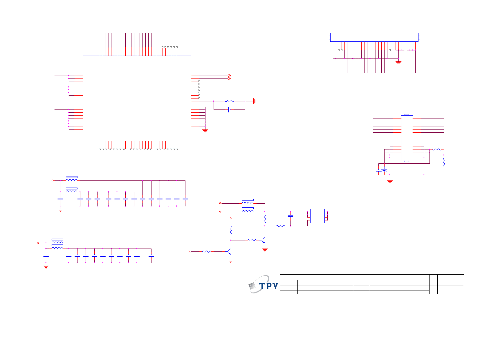
VCCK18
11/18
VCC3
C428
10uF/16V
GND
V33LV
VCC3I O
VCCK
VCCK
C417
10uF/16V
GND
1 2
1 2
GNDLV
1 2
1 2
FB413
120R/3000mA
FB410
120R/3000mA
C429
0.1uF25V
U400C
203
VCCLV(3.3V)
140
AVDD3V_LV(3. 3V)
170
AVDD3V_LV(3. 3V)
120
VCC3IO(3.3V)
106
VCC3IO(3.3V)
204
VCC3IO(3.3V)
241
VCC3IO(3.3V)
152
PVDD_LV(1. 8V)
90
VCCK(1.8V)
104
VCCK(1.8V)
119
VCCK(1.8V)
138
VCCK(1.8V)
172
VCCK(1.8V)
184
VCCK(1.8V)
205
VCCK(1.8V)
239
VCCK(1.8V)
HX6202A
FB407
300 OHM
FB408
300 OHM
C421
10uF/16V
C430
C431
0.1uF25V
C442
1uF/16V
0.1uF25V
PN swap for layout
TX3BP
TX2BN
TX1BN
TX3BN
TXCKBN
TX2BP
TXCKBP
TX1BP
143
147
144
145
142
146
148
FRSR 0P/LVB3P/EB7
FRSR 2P/LVB2P/EB3
FRSR 3P/LVB1P/EB1
FRSR 0N/LVB3N/EB6
FRSR 2N/LVB2N/EB2
FRSR 1P/LVBCKP/EB5
FRSR 1N/LVBCKN/ EB4
RSDS/LVDS
BRSR0N /OB6
BRSR0P/ OB7
BRSR1N /OB4
BRSR1P/ OB5
BRSR2N /OB2
BRSR2P/ OB3
BRSR3P/ OB1
175
174
177
176
179
178
180
V33LVV33LV
C443
C444
VCCK
C433
0.1uF25V
C418
1uF/16V
C434
0.1uF25V
1uF/16V
C432
0.1uF25V
TX3AN
TXCKAN
TX3AP
TX1AN
TXCKAP
TX1AP
TX0BN
TX0BP
149
150
151
FRSC LKP/LVB0P
FRSC LKN/LVB0N
FRSR 3N/LVB1N/EB0
BRSCLKN
BRSCLKP
BRSR3N /OB0
183
182
181
TX2AP
TX2AN
157
154
158
160
155
159
161
156
FRSG0P/ LVA3P/EG7
FRSG2P/ LVA2P/EG3
FRSG3P/ LVA1P/EG1
FRSG0N /LVA3N/EG6
FRSG2N /LVA2N/EG2
FRSG1P/ LVACKP/EG5
FRSG1N /LVACKN/EG4
BRSG0N/ OG6
BRSG0P/OG7
BRSG1N/ OG4
BRSG1P/OG5
BRSG2N/ OG2
BRSG2P/OG3
BRSG3P/OG1
188
187
190
189
192
191
194
193
PN swap for layout
0.1uF25V
C436
0.1uF25V
C420
0.1uF25V
C439
10uF/16V
C440
C441
10uF/16V
C437
C419
0.1uF25V
C435
0.1uF25V
TX0AP
TX0AN
163
165
162
164
166
FRSB1P/ ER5
FRSB2P/ ER3
FRSB1N /ER4
GPIO19/GVOF F/I2SDATI
FRSB0P/ LVA0P/ER7
GPIO20/OEV/ TTL_DE
FRSB0N /LVA0N/ER6
FRSG3N /LVA1N/EG0
GPIO21/C PV/TTL_HS
GPIO22/STV1/TTL_VS
GPIO25/FSTH1/ TTL_CLK
AVSS3V_LV(0V)
AVSS3V_LV(0V)
BRSB0N/ OR6
BRSB0P/OR 7
BRSB1N/ OR4
BRSB1P/OR 5
BRSB2P/OR 3
BRSG3N/ OG0
196
195
198
197
199
VCC3IO
VCC3IO
C422
C423
0.1uF25V
10uF/16V
0.1uF25V
167
169
168
FRSB3P/ ER1
FRSB2N /ER2
FRSB3N /ER0
GPIO18/GVON
GPIO23/POL
GPIO24/FTP
GPIO26/BSTH1
AVSS_LV(V)
PVSS_LV(0V)
GNDK(0V)
GNDK(0V)
GNDK(0V)
GNDK(0V)
BRSB2N/ OR2
BRSB3N/ OR0
BRSB3P/OR 1
200
202
201
C424
0.1uF25V
0.1uF25V
PANEL POWER
1:OFF ;
0:ON
PANEL_ON8
129
130
131
132
133
134
135
136
137
173
PI
186
153
171
141
139
105
240
185
C425
0.1uF25V
4.7K OHM 1/16W
R443
GND
AU_S0
AU_S1
PI
V12_ADP
5VSB
R436
13K OHM 1/10 W
5VSB
GND
AU_S0 7
AU_S1 7
C416
NC 0.1uF 25V
1 2FB411
300 OHM
FB412
1 2
NC 300 OHM
4.7K OHM 1/16W
R440
4.7K OHM 1/16W
R442
4.7K OHM 1/16W
Q407
PMBS3904
CN408
NC
GND
VCC5_PAN EL_IN VCC5_IN
R439
GND
Q406
PMBS3904
220K 1/10W 5%
C438
0.22uF
R441
T P V ( Top Victory Electronics Co . , Ltd. )
絬 隔 瓜 絪 腹
Key Component
Date
1
2
3
4
09)M2B LVDS
Q405
S
S
S
G
AO4449 -7A/-30V
CN405
123456789
VCC5_I N
TX0AN
30
TX1AN
28
TX2AN
26
TXCKAN
24
TX3AN
22
TX0BN
20
TX1BN
18
TX2BN
16
TXCKBN
14
TX3BN
12
10
8
6
4
2
R437
SELLVDS
R438
NC
Size
Rev
称爹
NC
A3
00
称爹
>
<
101112131415161718192021222324252627282930
GND
TX0AN
TX1AP
TX1AN
TX2AP
TX2AN
TX0AP
715G3364 G
912Wednesday , August 26, 2009
of
SELLVDS
TX0AP
29
TX1AP
27
TX2AP
25
TXCKAP
23
TX3AP
21
TX0BP
19
TX1BP
17
TX2BP
15
TXCKBP
13
TX3BP
11
9
7
5
3
1
VCC5_IN
+
LVDS CONN DIP 2.0
GND
TXCKAN
TX3AP
TX3AN
TXCKAP
C427
470UF16V
C426
0.1uF 50V
8
D
7
D
Panel Power
6
D
5
D
OEM MO DEL
TPV MODEL
PCB NAME
Sheet
43
Page 44
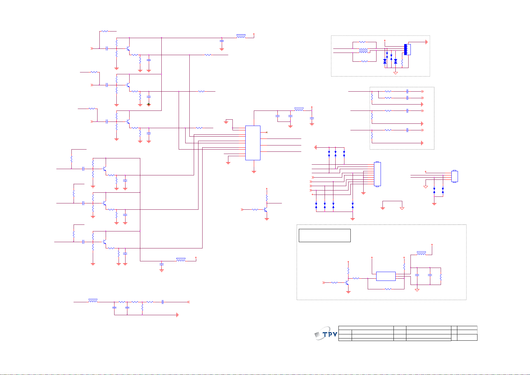
PB_IN3
usb_pr
R470
NC 0R05 1/10W 5%
Pr_SCALER
usb_pb
R471
NC 0R05 1/10W 5%
Pb_SCALER
usb_Y
R472
Y_SCALER
NC 0R05 1/10W 5%
Y_SCALER
PR2_IN4
Y_IN3
Y2_IN4
PB2_IN4
C669
NC 10UF16V
C670
NC 10UF16V
C671
NC 10UF16V
FB213
R213
R233
1 2
R209
C679
NC 10UF16V
0R05 1/10W 5%
C667
NC 10UF16V
0R05 1/10W 5%
C668
NC 10UF16V
R219
NC 4.7KΩ
R204
NC 10KΩ
NC 0R05 1/10W 5%
R217
NC 4.7KΩ
R220
NC 10KΩ
NC 0R05 1/10W 5%
NC 100Ω
R206
NC 4.7KΩ
R210
NC 10KΩ
NC 0R05 1/10W 5%
NC 100Ω
NC 0R05 1/10W 5%
NC 30R
USB_CVBS
0R05 1/10W 5%
PR_IN3
R199
NC 4.7KΩ
R203
NC 10KΩ
R208
NC 4.7KΩ
R207
NC 10KΩ
R198
NC 4.7KΩ
R221
NC 10KΩ
Q107
NC PMBS3904
R194
R211
NC 100Ω
Q111
NC PMBS3904
R195
R202
Q108
NC PMBS3904
R193
R215
R218
C170
NC
Q109
NC PMBS3904
R197
NC 0R05 1/10W 5%
R212
NC 100R 1/10W 5%
Q112
NC PMBS3904
R222
NC 0R05 1/10W 5%
R201
NC 100R 1/10W 5%
Q110
NC PMBS3904
R196
NC 0R05 1/10W 5%
R214
NC 100R 1/10W 5%
C182
NC 33pF
C180
NC 33pF
C176
NC 33pF
NC 180R 1/10W 5%
R205
C171
NC
C177
NC 270pF
C172
NC 270pF
C178
NC 270pF
NC 5.1K OHM 1/16W
R216
R200
NC 56R 1 /10W 5%
usb_pr
usb_pb
usb_Y
C174
NC 100pF
PR_IN3
Y_IN3
PB_IN3
C169
NC 0.1uF25V
FB108
1 2
NC 300 OHM
GND
R772
0R05 1/10W 5%
R773
0R05 1/10W 5%
VCC5
CVBS_3 5
R771
0R05 1/10W 5%
Y_IN0
PB_IN0
FB110
1 2
NC 300 OHM
C179
NC 100pF
PR_IN0
U107
2
S1A
3
S2A
5
S1B
6
S2B
11
S1C
10
S2C
14
S1D
13
Video_SEL8
S2D
1
IN
15
/EN
NC 10K OHM 1/16W
NC 1K OHM 1/16W
V_SEL
Low: Channel 2 /YPbPr2
High:Channel 1 /USB
VCC5
R728
NC 0.1 uF25V
16
VCC
4
DA
7
DB
12
DD
9
DC
GND
NC PI5 V330SQE
8
R726
C539
VCC5
GND
V_SEL
Q711
NC PMBS3904
FB109
VCC5
1 2
NC 300 OHM
C175
NC 100pF
PR_IN0
Y_IN0
PB_IN0
C523
NC 10uF/16V
Pr_SCALER
Y_SCALER
Pb_SCALER
USB_AUL7
USB_AUR7
IRDAT8
IR_EN8
VCC5
12
SP133
SP134
NC
NC
VBUS,5V
USB HOST,500mA,2.5W
Active low
POWER_ON1,8
USB_DM
USB_DP
NC
NC
SP138
SP137
1 2
12
12
SP132
NC
NC 10K OHM 1/16W
R733
NC 1K OHM 1/16W
R789
NC 0R05 1/10W 5%
4 1
3 2
L208
R790
NC 0R05 1/10W 5%
FOR EMI
Y_IN0
PB_IN0
PR_IN0
NC
SP139
1 2
1 2
12
SP136
NC
5VSB
R731
R732
NC 1K OHM 1/16W
Q709
NC PMBS3904
GND
VBUS
SP149
NC 90OHM
NC
ZD604
NC VPORT0603100 KV05
R144
NC 75 OHM 1/ 16W
R151
NC 75 OHM 1/ 16W
100R 1/10W 5%
R154
NC 75 OHM 1/ 16W
Near to IC
NC CONN
10
9
8
7
6
5
4
3
2
1
CN208
5VSB
NC 4.7K OHM 1/10W
U711
5
IN
4
EN
NC STMPS2171STR-SOT23-5
12
12
SP150
12
NC
USB_GND
R142
100R 1/10W 5%
R145
100R 1/10W 5%
R148
100R 1/10W 5%
R153
OUT
GND
FAULT
R757
NC 0 OHM 1/10W
12
ZD605
USB_GND
R647
1
2
3
1
2
3
4
C131
C135 1000pF
C137
C140
5VSB
1234
CN703
NC CONNNECTOR
6 5
R764
NC 0 OHM 1/10W
0.047uF
0.047uF
0.047uF
USB_DM
USB_DP
USB_GND
1 2
USB_GND
NC VPORT0603100 KV05
Y2 6
SOY2 6
GND
PB2 6
GND
PR2 6
GND
VBUS
12
SP140
NC
VBUS
FB414
NC 120R
C776
C777
NC 100pF
NC 10uF
12
SP141
NC
R646
NC 39K 1/10W 5%
4
3
2
1
NC CONN
CN206
44
T P V ( Top Victory Electronics Co . , Ltd. )
絬 隔 瓜 絪 腹
Key Component
10)COMPONENT2 & USB IN PUT
Date
OEM MODEL
TPV MOD EL
PCB NAME
Sheet
715G3364 G
of
10 12Wednesday, Augus t 26, 2009
C
Size
Rev
A
称爹
>
<
称爹
Page 45

9.2 Power Board
715G3332 1
1
+
2
CN903
-
2
N
1
L
4
NC
L902
3
13mH
0.47uF/275 V
C902
C904
680pF
R902
330K OHM 1/4W
R901
330K OHM 1/4W
!
L901
3
SG901
NC
13mH
C901
0.47uF/275V
12
NR901
NTCR
!
RV901
t
NC
F901
FUSE
!
3
1 2
FB901
1 2
BEAD
C913
0.1uF
BD901
D10XB60
124
C903
680pF
R903
330K OHM 1/4W
!
124
!
SOCKET
CN901
3
C910
1uF/450V
R910
300K OHM 1/4W
VCC
+
C914
47uF/50V
D901
1N4007-E3/73
1.5 MOHM +-5% 1/4W
100K OHM 1/8W
SG902
NC
R904
R927
NC
R928
125
67
8
R911
20K OHM 1/4W
C916
R917
NC
56K OHM 1/8W
R905
1.5 MOHM +-5% 1/4W
B+_390V
R924
1M OHM 1% 1/4W
R925
1M OHM 1% 1/4W
R926
1M OHM 1% 1/4W
L906
310uH
1R 1/8W 5%
R932
C912
100pF
678
OUT
VCC
GND
INV
COMP
MOT
123
4 5
R918
10K OHM 1/8W
C917
0.047uF
1.5 MOHM +-5% 1/4W
R964
2K OHM 1/8W
C922
C923
1uF
0.1uF
3.6K OHM 1/8W
D904
IN5408
CS ZCD
IC901
FAN7529MX
R909
2 1
R985
10 OHM 1/8W
R913
10K OHM 1/8W
C921
0.1uF
Q925
KTA1273
3
R929
10K OHM 1/4W
Q924
DTC144WKA
!
D902
FMN-1106S
D905
1N4148
R914
R915
470 OHM 1/8W
C915
470pF,50V
C918
0.47uF/25V
C943
0.047uF
R936
NC
R935
1K OHM 1/4W
C911
10nF
2
1
STP20NM60FP
3
ZD910
NC
1 2
D910
NC
R916
0.12 OHM 2W
C919
220pF,50V
R906
510KOHM +-5% 1/8W
VCC
R938
4.7K OHM 1/8W
R941
10K OHM 1/4W
1
2
FB
3
4 5
R942
51KOHM +-5% 1/4W
RV902
NC
Q901
R919
NC
4.7K OHM 1/8W
R937
IC903
BNO
COMP
(-)LATCH
CS GND
LD7523PS
1 2
R920
680K OHM +-1% 1/4W
R921
680K OHM +-1% 1/4W
R922
680K OHM +-1% 1/4W
R923
13K OHM 1% 1/8W
10K OHM 1/8W
R947
8
OVP
7
VCC
6
OUT
C944
220pF
FB902
BEAD
VCC
B+
C942
0.1uF
R933
1R 1/8W 5%
R945
1KOHM +-5% 1/4W
+
C940
NC
SARS01-V1
+
10uF/50V
R943
22 OHM 1/8W
FB903
1 2
BEAD
C920
120uF M 450V
R996
100K OHM 1/4W
C935
1000PF2KV
D940
100K OHM 1/4W
C941
D906
1N4148
R944
10K OHM 1/8W
+
C937
10uF/50V
MTZJ T-72 16B
R998
D942
ZD940
12
NC
Q921
KTD1691P
ZD930
C907
0.1uF
R997
100K OHM 1/4W
R999
100K OHM 1/4W
NC
Q903
STP10NK70ZFP
R946
0.36 OHM +-5%
B+_390V
2
1 2
C925
10nF
31
5
6
3
2
1
C939
0.01uF
B+
R939
10K OHM 1/4W
2.2 OHM 1/4W
R908
T902
POWER X'FMR
FB
43
R948
0.1 ohm
R962
4.7M OHM 1/4W
IC902
4 5
FB/OLP VCC
3
GND
2
D/ST
BR
1
D/ST
S/OCP
A6069H
R907
2.2 OHM 1/4W
12
11
10
9
8
7
R974
1K OHM 1/4W
12
IC970
EL817MC
R976
10K OHM 1/4W
IC971
AZ431AZ-AE1
B+
7
8
C933
10uF/50V
100 OHM 1/4W
3
1
R975
3.9KOHM +-5% 1/8W
C930
NC
SARS01-V1
JUMPER
+
C908
0.1uF
C924
0.001uF/250 V
R973
100 OHM 1/4W
R970
D970
SBR20010JST
2
D972
3
SBR20010JST
2
1
R977
100 OHM 1/4W
R951
100 OHM 1/4W
0.33uF
C932
1000PF2KV
R991
100K OHM 1/4W
R992
100K OHM 1/4W
D930
D932
D903
1N4148
C906
470pF/250V
C957
0.001uF
100K OHM 1/4W
100K OHM 1/4W
C934
0.1uF
C970
0.001uF
+
C973
470uF 35V
C952
0.001uF
1.8K OHM 1/4W
R993
R994
D931
AU02Z
R986
C972
0.001uF
+
R931
2.2 OHM 1/4W
C931
+
100uF/50V
L980
L
L951
C945
470uF 35V
R965
1.8K OHM 1/4W
L
1
2
3
4
5
C905
470pF/250V
T901
POWER X'FMR
C909
0.01uF
+
C975
470uF 35V
+
C946
470uF/25V
R967
1.8K OHM 1/4W
R980
NC
6
7
9
10
43
1.8K OHM 1/4W
R971
R978
24K OHM 1% 1/8W
R979
2KOHM +-1% 1/8W
R950
47 OHM 1/4W
R952
47 OHM 1/4W
3
D950
SBT15006JST
2
1
R954
100 OHM 1/4W
12
R955
IC950
1K OHM 1/8W
EL817MC
C955
R956
0.22uF/50V
1K OHM 1/8W
IC952
AZ431AZ-AE1
R988
1.8K OHM 1/4W
R987
27KOHM +-1% 1/4W
T P V ( Top Victory Electronics Co . , Ltd. )
絬 隔 瓜 絪 腹
Key Component
Date
+
C953
330uF 16V
A5V
R959
100K OHM 1% 1/8W
C949
0.1uF
R972
1.8K OHM 1/4W
C948
0.1uF
R966
6.8K OHM 1/4W
POWER
Wednesday , May 27, 2009
C950
0.001uF
C951
L950
0.001uF
L
R957
8.2KOHM +-1% 1/8W
R958
8.2KOHM +-1% 1/8W
+24V
+12V
R968
6.8K OHM 1/4W
C947
R960
1K OHM
12
IC951
EL817MC
Q950
PMBS3904
ZD970
MTZJ T-72 30B
ZD952
MTZJ T-72 15B
Q970
PMBS3904
R989
C956
0.1uF
D971
12
1N4148
D951
12
1N4148
R984
6.8K OHM 1/4W
of
0.1uF
10K OHM
R963
10K OHM 1/8W
R983
1K OHM 1/8W +-5%
C978
0.1uF
715G3332-I
+
C954
470uF 16V
43
+24V
+12V
A5V
1K 1/8W 5%
R969
6.8K OHM 1/4W
OEM MODEL Size
TPV MOD EL
PCB NAME
Sheet
+5V
PS_ON
R961
ON/OFF
PDIM
+12V
+24V
+5V
R981
100 OHM 1/8W
R982
1K OHM 1/8W +-5%
PS_ON
CN902
1
2
3
4
5
6
7
8
9
10
11
12
CONN
Custom
Rev
A
BBY MODEL
称爹
45
Page 46

DR1
D802
SCS0520P
C802
2.2uF 25V X7R
SCS0520P
1 2
DR2
D804
B+_390V
T801
50:50: 50
1
4
1 2
10
9
7
6
5
R801 0.1 ohm
D801
D803
12
SCS0520P
R802
100 OHM 1/8W
SCS0520P
12
R803
100 OHM 1/8W
C823
10nF
Q801
R832
10K OHM 1/4W +-5%
Q802
FQPF12N60C
R833
10K OHM 1/4W +-5%
FQPF12N60C
C803
1000pF
C822
1000pF
C801
1uF/450V
C804
1uF/450V
T802
P:S=50:45
5
6
3
2
1
12
11
10
9
8
7
TB
CN801
2
TA
CONN
N
L
TB
1
TA
PDIM
R807
240K OHM 1/8W
R812
150K OHM 1/8W
IS1
IS2
ON/OF F
D806
1N4148
D807
1N4148
R808
1M OHM 1/8W
C817
47N 50V
C818
47N 50V
62K OHM 1/8W
C808
1N 50V
100K OHM 1/8W
R828
68K OHM 1/8W
R830
68K OHM 1/8W
R805
VREF
VS
+12V
R806
3.3MOHM1/8W
C807
330PF/ 50V
R813
NC
R820
Q804
PMBS3904
R829
1M 1/8W
Q805
PMBS3904
R831
1M 1/8W
C810
4N7 50V
1K OHM 1/8W +-5%
ISEN
Q803
RK7002
L801
L
R817
R819
1M OHM 1/8W
CN802
5
VS
4
IS1
CONN
Rev
715G3332-1
称爹
3
2
1
IS1
IS2
IS2
B
A
BBY MODEL
C805
DR1
R816
51 OHM 1/8W
C815
0.0015uF/25V
+
470uF/25V
R809
NC
C806
0.1uF /50V
IC801
1
DRV1
DRV2
2
GND
3
4
5
6
7
8 9
VIN
ZCS
VREF
RT1
ENA
CT
ADIM
LCT
TIME R
PDIM
SSTCMP
VSEN ISEN
OZ9976GN
ISEN
16
15
14
13
12
11
10
C816
1500pF
絬 隔 瓜 絪 腹
Key Component
DR2
ENA
R811
1.5M OHM 1/8W
C809
C812
0.022uF/25V
R818
1.2K OHM 1/8W +-1%
R821
9.1K OHM 1/8W
T P V ( Top Victory Electronics Co . , Ltd. )
INVERTER
Wednes day , J uly 15, 2009
Date
1U 25V
VREF
51K OHM 1/8W +-5%
3
D805
BAV70
C819
NC(C1206)
R814
R804
10K OHM 1/8W
R810
100K OHM 1/8W
C811
R815
1U 25V
51K
1
2
R823
R822
NC
240 OHM 1/8W
OEM MO DE L S ize
TPV MO DEL
PCB NAME
Sheet
C820
680PF/ 50V
of
C813
4N7 50V
R825
NC
C814
2.2uF 25V X7R
R824
510 OHM 1/8W
R826
240 OHM 1/8W
R827
C821
510 OHM 1/8W
680PF/50V
46
Page 47

9.3 Inverter Board
715G3333 1
CN8802
CONN
CN8801
6
5
WIRE
4
3
2
1
1
L
N
TB
2
TA
VS
IS1
IS2
P1
P2
P4
P5
P6
R8801
100 OHM +-5% 1/8W
R8802
100 OHM +-5% 1/8W
R8806
100 OHM +-5% 1/8W
R8807
100 OHM +-5% 1/8W
R8809
100 OHM +-5% 1/8W
510 OHM 1/8W
R8810
510 OHM 1/8W
R8811
510 OHM 1/8W
R8812
510 OHM 1/8W
R8814
R8815
510 OHM 1/8W
D8801
1N4148
D8802
1N4148
D8804
1N4148
D8805
1N4148
D8807
1N4148
R8804
10KOHM +-5% 1/8W
C8801
1N 50V
D8822
LL4148
D8806
R8808
MTZJ T-72 5.1B
100KOHM +-5% 1/8W
R8805
100K OHM 1/8W
VS
T8801
POWER X'FMR
2
1
CN8803
CONN
3
D8808
1
2
BAV99
TA
D8814
2
BAV99
4
6
C8802
10pF/6KV
3
!
1
21
18N 50V
!
4
1 2
6
P1
C8803
10pF/6KV
C8814
C8815
18N 50V
R8818
1K OHM 1/8W +-5%
T8802
POWER X'FMR
POWER X'FMR
CN8804
CONN
D8809
2
BAV99
TB
T8805
D8813
2
BAV99
!
4
6
2
1
3
1
!
!
1 2
P2
18N 50V
C8816
T8804
4
POWER X'FMR
POWER X'FMR
6
CN8805
CONN
C8805
10pF/6KV
C8817
18N 50V
R8819
1K OHM 1/8W +-5%
21
4
T8803
6
2
1
C8804
10pF/6KV
3
3
D8815
1
1
2
BAV99
D8819
2
BAV99
21
!
1 2
P6
C8812
10pF/6KV
3
1
1K OHM 1/8W +-5%
T8806
4
POWER X'FMR
6
C8824
18N 50V
R8820
C8813
10pF/6KV
C8825
18N 50V
T8807
POWER X'FMR
CN8806
CONN
3
D8811
2
BAV99
!
!
T8808
4
6
2
1
C8808
10pF/6KV
3
D8817
1
1
2
BAV99
POWER X'FMR
1 2
6
P4
C8809
10pF/6KV
C8821
C8820
18N 50V
18N 50V
R8821
1K OHM 1/8W +-5%
絬 隔 瓜 絪 腹
Key Component
POWER X'FMR
CN8807
CONN
T P V ( Top Victory Electronics Co . , Ltd. )
Date
4
21
D8812
2
BAV99
T8809
2
1
3
1
INVER TER
4
6
D8818
2
BAV99
!
C8810
10pF/6KV
3
!
T8810
4
21
1
1 2
P5
18N 50V
C8822
POWER X'FMR
POWER X'FMR
6
CN8808
CONN
C8811
10pF/6KV
C8823
18N 50V
1K OHM 1/8W +-5%
!
21
4
T8811
6
C8806
C8818
2
10pF/6KV
of
11Friday , March 20, 2009
1NF 50V
R8816
39K OHM 1/8W
D8821
1N4148
R8817
6.8K OHM 1% 1/8W
715G3333-1
1
R8822
OEM MO DE L S ize
TPV MODEL
PCB NAME
Sheet
!
T8812
POWER X'FMR
4
IS1
IS2
1 2
6
C8807
C8819
10pF/6KV
1NF 50V
R8803
39K OHM 1/8W
D8820
1N4148
R8813
6.8K OHM 1% 1/8W
Rev
称爹
R8823
0 OHM 1/8W
B
A
BBY MODEL
47
Page 48

715G3690P01000003M
CN8802
CONN
1
2
3
TB
CN8801
CONN
P1
P2
6
5
4
3
2
1
VS
IS1
IS2
P3
R8801
100 OHM +- 5% 1/8W
R8802
100 OHM +- 5% 1/8W
R8806
100 OHM +- 5% 1/8W
R8811
R8812
R8814
D8801
1N4148
D8802
1N4148
D8804
1N4148
R8804
10KOHM + -5% 1/8W
C8801
1N 50V
R8807
1K OHM 1/8W
D8806
R8808
MTZJ T-72 5.1B
100KOHM + -5% 1/8W
R8805
100K OHM 1/8W
C8822
VS
CN8804
CONN
CN8803
CONN
2
1
5K1 + -5% 1/8W
POWER X'FMR
1
2
3
C8802
5pF/ 6KV
39KOHM +-1% 1/8W
VS
TA
4
T8801A
6
330PF 50V
R8816
D8821
R8817
1N4148
R8823
1K OHM +-5% 1/8W
C8818
TA
T8801
POWER X'FMR
4
21
6
IS2
C8819
IS2
330PF 50V
R8803
39KOHM +-1% 1/8W
R8813
5K1 + -5% 1/8W
T8802A
POWER X'FMR
21
IS1
T8802
POWER X'FMR
1 2
1 2
IS1
C8803
5pF/6KV
D8820
1N4148
1K OHM 1/8W +-5%
4
6
4
6
R8818
T8803A
POWER X'FMR
4
6
CN 8805
CONN
3
1
2
D8809
D-BAV99-7-F
21
4
6
POWER X'FMR
2
1
C8804
5pF/6KV
3
2
D8815
D-BAV99-7-F
T8804A
POWER X'FMR
21
4
6
P1 P2
4
T8804
1 2
1 2
6
P1
C8816
6N8 50V
POWER X'FMR
CN8806
CONN
C8805
5pF/6KV
2
C8817
6N8 50V
R8819
1K OHM 1/8W +-5%
D8813
D-BAV99-7-F
T8803
1
POWER X'FMR
T8805A
4
6
2
1
3
1
510 OHM +- 5% 1/8W
2
48
21
4
6
P2
T8805
POWER X'FMR
C8812
5pF/6KV
3
C8824
6N8 50V
1
D8819 D -BAV99-7-F
R8820
1K OHM 1/8W +-5%
510 OHM +- 5% 1/8W
510 OHM +- 5% 1/8W
T8806A
POWER X'FMR
21
1 2
1 2
T8806
POWER X'FMR
C8813
5pF/6KV
C8825
6N8 50V
4
6
4
6
CN8807
CONN
2
D8811
D-BAV99-7-F
3
POWER X'FMR
4
6
2
1
1
2
T8807A
21
POWER X'FMR
C8808
5pF/ 6KV
3
C8820
6N8 50V
1
D8817
D-BAV99-7-F
4
6
T8807
T8808A
POWER X'FMR
21
P3
1 2
1 2
T8808
POWER X'FMR
P3
C8809
5pF/6KV
C8821
6N8 50V
220pF K 50V X7R
4
6
TB
4
6
Page 49

9.4 Key Board
715G3400 1
R01
20K OHM 1% 1/10W
SW01
VOL+
C01
NC
CN01
1
2
3
4
CONN
033G3802 4H
3V3_STB
PWR-SW
FUNC_KEY
C08
NC
JR02
0 OHM 1/4W
FUNC_KEY
3V3_STB
R09
NC
R10
NC
R07
100 OHM 1% 1/10W
R02
8.2K1/ 10W 1%
R03
4.32K 1% 1/10W
R04
2.74K 1% 1/10W
R05
1.8K OH M 1% 1/10W
SW02
VOL-
C02
NC
SW03
CH+
C03
NC
SW04
CH-
C04
NC
SW05
MENU
C05
NC
SW06
Source Select
C06
NC
PWR-SW
0 OHM 1/8W
JR01
R08
100 OHM 1% 1/10W
T P V ( Top Victory Electronics Co . , Ltd. )
絬 隔 瓜 絪 腹
Key Component
Keyp ad
Wednes day , J une 24, 20 09
Date
49
SW07
C07
NC
077G 603 AI HJ
Power ON/OFF
OEM MODEL Size
TPV MODEL
PCB NAME
Sheet
715G3400-D
of
Rev
称爹
B
<
称爹
Custom
>
Page 50

9.5 IR Board
715G3394 2
CN01
CONN
D3V3
12
U01
LED GPB2603C/R001-HB
R001 22K 1/10W 5%
C01
3.3uF/ 10V
R002
22K 1/10W 5%
D01 LED
RED
GREEN
D3V3
3
1
2
81G 12 10 EL
LIGHT_SENSOR
6
LED_R
5
LED_G
4
3
IRRV
2
1
7 8
R003 4.7K 1/8W 5%
C02
0.1uF/ 16V
C03
NC/4.7uF/16V
U02
1
VOUT
2
GND
3
VCC
KSM-603TM2E
56G 627 42
033G8032 6F
HR
GND_PIN
GND PIN
1
T P V ( Top Victory Electronics Co . , Ltd. )
絬 隔 瓜 絪 腹
Key Component
Date
01-IR&LED
50
OEM MO D EL Size
TPV MODEL
PCB N AME
Sheet
715G3394
11Wednesday , May 06, 2009
of
Rev
称爹
Custom
B
<
称爹
>
Page 51

10. Exploded View
51
Page 52

11. BOM List
Note: The parts information listed below are for reference only, and are subject to change without notice. Please go
to http://cs.tpv.com.cn/hello1.asp
E329MANS4WACNN
Location Part No. Description Remark
040G 58162435A P/N LABEL FOR MANUAL PE BAG
052G 1185 1 BIG TAPE(Y1200141)
052G 1186 SMALL TAPE
052G 1211 B CONDUCTIVE TAPE 85MM *40MM *0.09MM
052G 2191 A PAPER TAPE
E07801 078G0120 2 K SPEAKER 6 OHM 12W 160X42MM
E07801 078G0120 2 Y SPEAKER 6 OHM 12W 160X42MM 2nd source
089G 725CAA DB D-SUB CABLE
089G408A18N IS POWER CORD WALL-OUT FOR ITALY
E09201 092TB1JX1A3WGC BATTERY LR03(EA)2S/G AAA
E09201 092TB1JX1A3WGM BATTERY FOR ALL EXPORT MODE LR03
095G801312D 42 HARNESS 12P-12P 150MM
095G8021 3D 52 HARNESS 3P-3P 300MM
E09503 095T8014 4D557 WIRE HARNESS 4P(PLUG)-B&R+B&W
E09503 095T8014 4X557 WIRE HARNESS 4P(PLUG)-B&R+B&W 2nd source
095T8018 3DH57 LVDS CABLE 30P-30P 350MM
098GRABD2NEACR REMOTE CONTROL RC2443801/01
0M1G 340 4120 SCREW
0M1G 930 8 47 CR3 SCREW
0M1G 940 16 47 CR3 SCREW
0M1G1730 8120 SCREW
0M1G1730 10120 SCREW 42A9930016
0Q1G 930 10 47 CR3 SCREW
0Q1G 940 16 47 CR3 SCREW
E750 750TVM315BN311N000 PANEL V315B3-LN3 C1/C2 TW CMO
E750 750TVM315BN313N000 PANEL V315B3-LN3 C1/C2 NH CMO 2nd source
756TQ9CB AS003 01 MAIN BOARD-CBPF9A4SY2
U402 056G1133923 IC MX25L4005AM2C-12G SOP-8
SMTF-U402 100TAHMK002C11 MCU ASS'Y-056G1133923
040G 45762412B CBPC LABEL
CN602 033G3802 4B Y W WAFER
CN405 033G8027 30 WAFER 30P 2.0MM DIP DUAL ROW
CN700 033T327812D WAFER 12P PLUG
CN602 033T3802 4B Y CONNECTOR
CN400 033T380210B Y CONNECTOR
R300 061G 208470 64 RST MOFR 47OHM +-5% 1W
R303 061G 208470 64 RST MOFR 47OHM +-5% 1W
C779 067G 305101 3T 100UF 16V 105C
C640 067G215P4714AV
C660 067G215P4714AV
C710 067G215V471 6N
C636 067T215P4716AV CAP 105C 470UF M 35V
CN102 088G 78 13942 C RCA JACK 1*5 G/B/R/W/R AV5-8.4-02-01
CN103 088G 78 13942 C RCA JACK 1*5 G/B/R/W/R AV5-8.4-02-01
CN103 088G 78 13942 YG RCA JACK 1*5 G/B/R/W/R RCA-512DF
CN102 088G 78 13942 YG RCA JACK 1*5 G/B/R/W/R RCA-512DF
CN106 088G 7813A38C RCA JACK 1*3 Y/W/R V/A
CN104 088G 7813A38C RCA JACK 1*3 Y/W/R V/A
for the latest information.
CAP 105℃ 470UF M 25V
CAP 105℃ 470UF M 25V
CAP 105℃ 470UF M 35V
52
Page 53

CN105 088G 7813A39C S JACK + RCA JACK 1*3 Y/W/R
CN600 088G 30211K PHONE JACK 5PIN
CN601 088T 78 8 9C RCA JACK 1*1 W/R V/A
CN105 088T 78 13A39 YG S JACK + RCA JACK 1*3 Y/W/R RCA-333S-010
CN101 088T 30252C PHONE JACK 3.5MM 3P V/A GREEN
CN101 088T 302A17 YG PHONE JACK 3.5MM 3P V/T GREEN
CN100 088T 35315F VC D-SUB 15PIN VERTICAL CONNECTOR
CN100 088T 35315F VD D-SUB 15PIN FEMALE VERTICAL WITH SCREW 2nd source
090G 372 2 HEAT SINK
X400 093G 2270B H XAT024576FK1H-3OHX AT-49 24.576MHZ
TU100 094TNTSC MN 7L TUNER M15WPP-4N-E
C651 067G 305100 3T 10UF 16V
C414 067G 305100 3T 10UF 16V
C746 067G 305100 7T
C736 067G 305100 7T
C732 067G 305100 7T
C778 067G 305101 3T 100UF 16V 105C
C720 067G 305101 3T 100UF 16V 105C
C728 067G 305101 3T 100UF 16V 105C
C717 067G 305101 3T 100UF 16V 105C
C712 067G 305101 3T 100UF 16V 105C
C672 067G 305101 3T 100UF 16V 105C
C308 067G 305101 3T 100UF 16V 105C
C303 067G 305101 3T 100UF 16V 105C
C301 067G 305101 3T 100UF 16V 105C
C300 067G 305101 3T 100UF 16V 105C
C729 067G 305101 3T 100UF 16V 105C
C763 067G 305221 2T 105C RADIALE-CAPACTOR 220UF 10V
C702 067G 305221 3T 220UF/16V
C715 067G 305221 3T 220UF/16V
C721 067G 305221 3T 220UF/16V
C410 067G 305470 3T 47UF +-20% 16V
C427 067G 3054713PT CAP 105C 470UF M 16V 8*12
C707 067G 3054713PT CAP 105C 470UF M 16V 8*12
U400 056G 562595 IC HX6202-A090QAG 1080P QFP-256
U705 056G 563 7 IC AIC1084-33PMTR-R AIC
U700 056G 563 31 IC AZ1117D-1.8-E1
U703 056G 563 52 IC AP1117D33G-13 TO252-3L DIODES
U702 056G 563 52 IC AP1117D33G-13 TO252-3L DIODES
U300 056G 585 11 IC AZ1117D-5.0-E1 AAC
U600 056G 614 1 74HC4052D S016 PHLIPS
U603 056G 616518 IC R2A15112FP HTQFP48
U401 056G113353A IC M24C32-WMN6T SO-8 ST
U402 056G1133923 IC MX25L4005AM2C-12G SOP-8
U707 056T 563952 IC SC4524BSETRT SO-8
U601 056T 616516 IC APA2176AQBITRL TQFN3X3-16
Q708 057G 417 4 PMBS3904/PHILIPS-SMT(04)
Q712 057G 417 4 PMBS3904/PHILIPS-SMT(04)
Q103 057G 417 4 PMBS3904/PHILIPS-SMT(04)
Q104 057G 417 4 PMBS3904/PHILIPS-SMT(04)
Q105 057G 417 4 PMBS3904/PHILIPS-SMT(04)
Q707 057G 417 4 PMBS3904/PHILIPS-SMT(04)
Q706 057G 417 4 PMBS3904/PHILIPS-SMT(04)
Q704 057G 417 4 PMBS3904/PHILIPS-SMT(04)
105℃ 10UF +-20% 50V
105℃ 10UF +-20% 50V
105℃ 10UF +-20% 50V
53
Page 54

Q700 057G 417 4 PMBS3904/PHILIPS-SMT(04)
Q603 057G 417 4 PMBS3904/PHILIPS-SMT(04)
Q602 057G 417 4 PMBS3904/PHILIPS-SMT(04)
Q601 057G 417 4 PMBS3904/PHILIPS-SMT(04)
Q508 057G 417 4 PMBS3904/PHILIPS-SMT(04)
Q506 057G 417 4 PMBS3904/PHILIPS-SMT(04)
Q505 057G 417 4 PMBS3904/PHILIPS-SMT(04)
Q504 057G 417 4 PMBS3904/PHILIPS-SMT(04)
Q502 057G 417 4 PMBS3904/PHILIPS-SMT(04)
Q500 057G 417 4 PMBS3904/PHILIPS-SMT(04)
Q410 057G 417 4 PMBS3904/PHILIPS-SMT(04)
Q407 057G 417 4 PMBS3904/PHILIPS-SMT(04)
Q406 057G 417 4 PMBS3904/PHILIPS-SMT(04)
Q413 057G 417 6 PMBS3906/PHILIPS-SMT(06)
Q403 057G 417 6 PMBS3906/PHILIPS-SMT(06)
Q401 057G 417512 MMBT3906
Q400 057G 417512 MMBT3906
Q102 057G 417512 MMBT3906
Q705 057G 763 79 FET AO4449 -7A/-30V SOIC-8
Q405 057G 763 79 FET AO4449 -7A/-30V SOIC-8
Q501 057G 763904 TRA FET 2N7002 SOT-23 PHILIPS
RP400 061G 125103 8 RST CHIP AR 8P4R 10 KOHM +-5% 1/16W
RP401 061G 125103 8 RST CHIP AR 8P4R 10 KOHM +-5% 1/16W
RP402 061G 125103 8 RST CHIP AR 8P4R 10 KOHM +-5% 1/16W
RP403 061G 125103 8 RST CHIP AR 8P4R 10 KOHM +-5% 1/16W
RP600 061G 125103 8 RST CHIP AR 8P4R 10 KOHM +-5% 1/16W
RP601 061G 125103 8 RST CHIP AR 8P4R 10 KOHM +-5% 1/16W
RP602 061G 125103 8 RST CHIP AR 8P4R 10 KOHM +-5% 1/16W
RP603 061G 125103 8 RST CHIP AR 8P4R 10 KOHM +-5% 1/16W
R545 061G0402000 RST CHIP MAX 0R05 1/16W
R600 061G0402000 RST CHIP MAX 0R05 1/16W
R506 061G0402000 RST CHIP MAX 0R05 1/16W
R509 061G0402000 RST CHIP MAX 0R05 1/16W
R517 061G0402000 RST CHIP MAX 0R05 1/16W
R518 061G0402000 RST CHIP MAX 0R05 1/16W
R531 061G0402000 RST CHIP MAX 0R05 1/16W
R533 061G0402000 RST CHIP MAX 0R05 1/16W
R544 061G0402000 RST CHIP MAX 0R05 1/16W
R308 061G0402000 RST CHIP MAX 0R05 1/16W
R313 061G0402000 RST CHIP MAX 0R05 1/16W
R316 061G0402000 RST CHIP MAX 0R05 1/16W
R416 061G0402000 RST CHIP MAX 0R05 1/16W
R417 061G0402000 RST CHIP MAX 0R05 1/16W
R448 061G0402000 RST CHIP MAX 0R05 1/16W
R451 061G0402000 RST CHIP MAX 0R05 1/16W
R452 061G0402000 RST CHIP MAX 0R05 1/16W
R310 061G0402101 RST CHIPR 100 OHM +-5% 1/16W
R608 061G0402101 RST CHIPR 100 OHM +-5% 1/16W
R609 061G0402101 RST CHIPR 100 OHM +-5% 1/16W
R719 061G0402102 RST CHIPR 1 KOHM +-5% 1/16W
R718 061G0402102 RST CHIPR 1 KOHM +-5% 1/16W
R524 061G0402102 RST CHIPR 1 KOHM +-5% 1/16W
R522 061G0402102 RST CHIPR 1 KOHM +-5% 1/16W
R507 061G0402102 RST CHIPR 1 KOHM +-5% 1/16W
54
Page 55

R500 061G0402102 RST CHIPR 1 KOHM +-5% 1/16W
R404 061G0402102 RST CHIPR 1 KOHM +-5% 1/16W
R403 061G0402102 RST CHIPR 1 KOHM +-5% 1/16W
R454 061G0402103 RST CHIPR 10 KOHM +-5% 1/16W
R453 061G0402103 RST CHIPR 10 KOHM +-5% 1/16W
R446 061G0402103 RST CHIPR 10 KOHM +-5% 1/16W
R423 061G0402103 RST CHIPR 10 KOHM +-5% 1/16W
R422 061G0402103 RST CHIPR 10 KOHM +-5% 1/16W
R411 061G0402103 RST CHIPR 10 KOHM +-5% 1/16W
R410 061G0402103 RST CHIPR 10 KOHM +-5% 1/16W
R409 061G0402103 RST CHIPR 10 KOHM +-5% 1/16W
R408 061G0402103 RST CHIPR 10 KOHM +-5% 1/16W
R407 061G0402103 RST CHIPR 10 KOHM +-5% 1/16W
R160 061G0402103 RST CHIPR 10 KOHM +-5% 1/16W
R120 061G0402103 RST CHIPR 10 KOHM +-5% 1/16W
R119 061G0402103 RST CHIPR 10 KOHM +-5% 1/16W
R716 061G0402103 RST CHIPR 10 KOHM +-5% 1/16W
R625 061G0402103 RST CHIPR 10 KOHM +-5% 1/16W
R624 061G0402103 RST CHIPR 10 KOHM +-5% 1/16W
R619 061G0402103 RST CHIPR 10 KOHM +-5% 1/16W
R527 061G0402103 RST CHIPR 10 KOHM +-5% 1/16W
R525 061G0402103 RST CHIPR 10 KOHM +-5% 1/16W
R523 061G0402103 RST CHIPR 10 KOHM +-5% 1/16W
R513 061G0402103 RST CHIPR 10 KOHM +-5% 1/16W
R511 061G0402103 RST CHIPR 10 KOHM +-5% 1/16W
R502 061G0402103 RST CHIPR 10 KOHM +-5% 1/16W
R501 061G0402103 RST CHIPR 10 KOHM +-5% 1/16W
R455 061G0402103 RST CHIPR 10 KOHM +-5% 1/16W
R510 061G0402105 RST CHIPR 1MOHM +-5% 1/16W
R155 061G0402201 RST CHIP 200R 1/16W 5%
R714 061G0402223 RST CHIPR 22 KOHM +-5% 1/16W
R158 061G0402271 RST CHIP 270R 1/16W 5%
R508 061G0402273 RST CHIP 27K 1/16W 5%
R542 061G0402391 RST CHIPR 390 OHM +-5% 1/16W
R543 061G0402391 RST CHIPR 390 OHM +-5% 1/16W
R443 061G0402472 RST CHIPR 4.7 KOHM +-5% 1/16W
R442 061G0402472 RST CHIPR 4.7 KOHM +-5% 1/16W
R440 061G0402472 RST CHIPR 4.7 KOHM +-5% 1/16W
R439 061G0402472 RST CHIPR 4.7 KOHM +-5% 1/16W
R402 061G0402472 RST CHIPR 4.7 KOHM +-5% 1/16W
R401 061G0402472 RST CHIPR 4.7 KOHM +-5% 1/16W
R400 061G0402472 RST CHIPR 4.7 KOHM +-5% 1/16W
R620 061G0402473 RST CHIPR 47 KOHM +-5% 1/16W
R616 061G0402473 RST CHIPR 47 KOHM +-5% 1/16W
R611 061G0402473 RST CHIPR 47 KOHM +-5% 1/16W
R530 061G0402473 RST CHIPR 47 KOHM +-5% 1/16W
R528 061G0402473 RST CHIPR 47 KOHM +-5% 1/16W
R516 061G0402473 RST CHIPR 47 KOHM +-5% 1/16W
R515 061G0402473 RST CHIPR 47 KOHM +-5% 1/16W
R505 061G0402473 RST CHIPR 47 KOHM +-5% 1/16W
R503 061G0402473 RST CHIPR 47 KOHM +-5% 1/16W
R447 061G0402562 RST CHIP 5K6 1/16W 5%
R157 061G0402750 RST CHIPR 75 OHM +-5% 1/16W
R769 061G0603000 RST CHIP MAX 0R05 1/10W
55
Page 56

R770 061G0603000 RST CHIP MAX 0R05 1/10W
R774 061G0603000 RST CHIP MAX 0R05 1/10W
R209 061G0603000 RST CHIP MAX 0R05 1/10W
R213 061G0603000 RST CHIP MAX 0R05 1/10W
R233 061G0603000 RST CHIP MAX 0R05 1/10W
R771 061G0603000 RST CHIP MAX 0R05 1/10W
R772 061G0603000 RST CHIP MAX 0R05 1/10W
R773 061G0603000 RST CHIP MAX 0R05 1/10W
R760 061G0603000 RST CHIP MAX 0R05 1/10W
R759 061G0603000 RST CHIP MAX 0R05 1/10W
R152 061G0603000 RST CHIP MAX 0R05 1/10W
R147 061G0603000 RST CHIP MAX 0R05 1/10W
R141 061G0603000 RST CHIP MAX 0R05 1/10W
R138 061G0603000 RST CHIP MAX 0R05 1/10W
R132 061G0603000 RST CHIP MAX 0R05 1/10W
R127 061G0603000 RST CHIP MAX 0R05 1/10W
L602 061G0603000 RST CHIP MAX 0R05 1/10W
R784 061G0603100 1F RST CHIPR 1 KOHM +-1% 1/10W
R783 061G0603100 1F RST CHIPR 1 KOHM +-1% 1/10W
R130 061G0603101 RST CHIPR 100 OHM +-5% 1/10W
R133 061G0603101 RST CHIPR 100 OHM +-5% 1/10W
R139 061G0603101 RST CHIPR 100 OHM +-5% 1/10W
R142 061G0603101 RST CHIPR 100 OHM +-5% 1/10W
R145 061G0603101 RST CHIPR 100 OHM +-5% 1/10W
R148 061G0603101 RST CHIPR 100 OHM +-5% 1/10W
R153 061G0603101 RST CHIPR 100 OHM +-5% 1/10W
R175 061G0603101 RST CHIPR 100 OHM +-5% 1/10W
R183 061G0603101 RST CHIPR 100 OHM +-5% 1/10W
FB100 061G0603101 RST CHIPR 100 OHM +-5% 1/10W
FB102 061G0603101 RST CHIPR 100 OHM +-5% 1/10W
R171 061G0603101 RST CHIPR 100 OHM +-5% 1/10W
R179 061G0603101 RST CHIPR 100 OHM +-5% 1/10W
R128 061G0603101 RST CHIPR 100 OHM +-5% 1/10W
R314 061G0603101 RST CHIPR 100 OHM +-5% 1/10W
R315 061G0603101 RST CHIPR 100 OHM +-5% 1/10W
R427 061G0603101 RST CHIPR 100 OHM +-5% 1/10W
R444 061G0603101 RST CHIPR 100 OHM +-5% 1/10W
R445 061G0603101 RST CHIPR 100 OHM +-5% 1/10W
R791 061G0603101 RST CHIPR 100 OHM +-5% 1/10W
R792 061G0603101 RST CHIPR 100 OHM +-5% 1/10W
R101 061G0603101 RST CHIPR 100 OHM +-5% 1/10W
R103 061G0603101 RST CHIPR 100 OHM +-5% 1/10W
R107 061G0603101 RST CHIPR 100 OHM +-5% 1/10W
R112 061G0603101 RST CHIPR 100 OHM +-5% 1/10W
R123 061G0603101 RST CHIPR 100 OHM +-5% 1/10W
R124 061G0603101 RST CHIPR 100 OHM +-5% 1/10W
R434 061G0603102 RST CHIPR 1K OHM +-5% 1/10W
R459 061G0603102 RST CHIPR 1K OHM +-5% 1/10W
R786 061G0603102 RST CHIPR 1K OHM +-5% 1/10W
R785 061G0603102 RST CHIPR 1K OHM +-5% 1/10W
R788 061G0603102 RST CHIPR 1K OHM +-5% 1/10W
R787 061G0603102 RST CHIPR 1K OHM +-5% 1/10W
R782 061G0603102 RST CHIPR 1K OHM +-5% 1/10W
R781 061G0603102 RST CHIPR 1K OHM +-5% 1/10W
56
Page 57

R712 061G0603102 RST CHIPR 1K OHM +-5% 1/10W
R708 061G0603102 RST CHIPR 1K OHM +-5% 1/10W
R706 061G0603102 RST CHIPR 1K OHM +-5% 1/10W
R700 061G0603102 RST CHIPR 1K OHM +-5% 1/10W
R612 061G0603102 RST CHIPR 1K OHM +-5% 1/10W
R737 061G0603103 RST CHIPR 10 KOHM +-5% 1/10W
R725 061G0603103 RST CHIPR 10 KOHM +-5% 1/10W
R639 061G0603103 RST CHIPR 10 KOHM +-5% 1/10W
R638 061G0603103 RST CHIPR 10 KOHM +-5% 1/10W
R637 061G0603103 RST CHIPR 10 KOHM +-5% 1/10W
R622 061G0603103 RST CHIPR 10 KOHM +-5% 1/10W
R526 061G0603103 RST CHIPR 10 KOHM +-5% 1/10W
R512 061G0603103 RST CHIPR 10 KOHM +-5% 1/10W
R432 061G0603103 RST CHIPR 10 KOHM +-5% 1/10W
R430 061G0603103 RST CHIPR 10 KOHM +-5% 1/10W
R149 061G0603104 RST CHIPR 100 KOHM +-5% 1/10W
R137 061G0603104 RST CHIPR 100 KOHM +-5% 1/10W
R136 061G0603104 RST CHIPR 100 KOHM +-5% 1/10W
R118 061G0603104 RST CHIPR 100 KOHM +-5% 1/10W
R117 061G0603104 RST CHIPR 100 KOHM +-5% 1/10W
R164 061G0603104 RST CHIPR 100 KOHM +-5% 1/10W
R163 061G0603104 RST CHIPR 100 KOHM +-5% 1/10W
R150 061G0603104 RST CHIPR 100 KOHM +-5% 1/10W
R187 061G0603104 RST CHIPR 100 KOHM +-5% 1/10W
R188 061G0603104 RST CHIPR 100 KOHM +-5% 1/10W
R191 061G0603104 RST CHIPR 100 KOHM +-5% 1/10W
R192 061G0603104 RST CHIPR 100 KOHM +-5% 1/10W
R424 061G0603105 RST CHIPR 1M OHM +-5% 1/10W
R436 061G0603133 RST CHIPR 13 KOHM +-5% 1/10W
R738 061G0603150 2F RST CHIPR 15 KOHM +-1% 1/10W
R159 061G0603151 RST CHIPR 150 OHM +-5% 1/10W
R536 061G0603160 1F RST CHIPR 1.6 KOHM +-1% 1/10W
R309 061G0603180 RST CHIPR 18 OHM +-5% 1/10W
R182 061G0603180 RST CHIPR 18 OHM +-5% 1/10W
R178 061G0603180 RST CHIPR 18 OHM +-5% 1/10W
R174 061G0603180 RST CHIPR 18 OHM +-5% 1/10W
R170 061G0603180 RST CHIPR 18 OHM +-5% 1/10W
R156 061G0603183 RST CHIPR 18 KOHM +-5% 1/10W
R736 061G0603202 RST CHIPR 2 KOHM +-5% 1/10W
R793 061G0603221 RST CHIPR 220 OHM +-5% 1/10W
R104 061G0603222 RST CHIPR 2.2 KOHM +-5% 1/10W
R110 061G0603222 RST CHIPR 2.2 KOHM +-5% 1/10W
R441 061G0603224 RST CHIPR 220 KOHM +-5% 1/10W
R734 061G0603229 RST CHIPR 2.2 OHM +-5% 1/10W
R185 061G0603273 RST CHIPR 27 KOHM +-5% 1/10W
R186 061G0603273 RST CHIPR 27 KOHM +-5% 1/10W
R189 061G0603273 RST CHIPR 27 KOHM +-5% 1/10W
R190 061G0603273 RST CHIPR 27 KOHM +-5% 1/10W
R799 061G0603274 RST CHIPR 270 KOHM +-5% 1/10W
R102 061G0603330 RST CHIPR 33 OHM +-5% 1/10W
R109 061G0603330 RST CHIPR 33 OHM +-5% 1/10W
R615 061G0603333 RST CHIPR 33KOHM +-5% 1/10W
R715 061G0603472 RST CHIPR 4.7K OHM +-5% 1/10W
R711 061G0603472 RST CHIPR 4.7K OHM +-5% 1/10W
57
Page 58

R703 061G0603472 RST CHIPR 4.7K OHM +-5% 1/10W
R610 061G0603472 RST CHIPR 4.7K OHM +-5% 1/10W
R421 061G0603472 RST CHIPR 4.7K OHM +-5% 1/10W
R420 061G0603472 RST CHIPR 4.7K OHM +-5% 1/10W
R167 061G0603472 RST CHIPR 4.7K OHM +-5% 1/10W
R165 061G0603472 RST CHIPR 4.7K OHM +-5% 1/10W
R166 061G0603473 RST CHIPR 47 KOHM +-5% 1/10W
R168 061G0603473 RST CHIPR 47 KOHM +-5% 1/10W
R717 061G0603473 RST CHIPR 47 KOHM +-5% 1/10W
R621 061G0603512 RST CHIPR 5.1 KOHM +-5% 1/10W
R146 061G0603512 RST CHIPR 5.1 KOHM +-5% 1/10W
R143 061G0603512 RST CHIPR 5.1 KOHM +-5% 1/10W
R134 061G0603512 RST CHIPR 5.1 KOHM +-5% 1/10W
R131 061G0603512 RST CHIPR 5.1 KOHM +-5% 1/10W
R311 061G0603560 RST CHIPR 56 OHM +-5% 1/10W
R184 061G0603560 RST CHIPR 56 OHM +-5% 1/10W
R180 061G0603560 RST CHIPR 56 OHM +-5% 1/10W
R176 061G0603560 RST CHIPR 56 OHM +-5% 1/10W
R172 061G0603560 RST CHIPR 56 OHM +-5% 1/10W
FB707 061G0603680 RST CHIPR 68 OHM +-5% 1/10W
R161 061G0603681 RST CHIPR 680 OHM +-5% 1/10W
R162 061G0603681 RST CHIPR 680 OHM +-5% 1/10W
R735 061G0603683 RST CHIPR 68K OHM +-5% 1/10W
R114 061G0603683 RST CHIPR 68K OHM +-5% 1/10W
R115 061G0603683 RST CHIPR 68K OHM +-5% 1/10W
R105 061G0603750 RST CHIPR 75 OHM +-5% 1/10W
R108 061G0603750 RST CHIPR 75 OHM +-5% 1/10W
R113 061G0603750 RST CHIPR 75 OHM +-5% 1/10W
R129 061G0603750 RST CHIPR 75 OHM +-5% 1/10W
R135 061G0603750 RST CHIPR 75 OHM +-5% 1/10W
R140 061G0603750 RST CHIPR 75 OHM +-5% 1/10W
R405 061T0603102 2F RST CHIPR 10.2 KOHM +-1% 1/10W
R406 061T0603102 2F RST CHIPR 10.2 KOHM +-1% 1/10W
C745 065G0603101 31 CER1 0603 NP0 50V 100P PM5 R
C685 065G0603103 32 CAP CHIP 0603 0.01UF K 50V X7R
C684 065G0603103 32 CAP CHIP 0603 0.01UF K 50V X7R
C683 065G0603103 32 CAP CHIP 0603 0.01UF K 50V X7R
C682 065G0603103 32 CAP CHIP 0603 0.01UF K 50V X7R
C751 065G0603104 12 CER2 0603 X7R 16V 100N P
C752 065G0603104 12 CER2 0603 X7R 16V 100N P
C761 065G0603104 12 CER2 0603 X7R 16V 100N P
C780 065G0603104 12 CER2 0603 X7R 16V 100N P
C143 065G0603104 32 CHIP 0.1UF 50V X7R
C302 065G0603104 32 CHIP 0.1UF 50V X7R
C304 065G0603104 32 CHIP 0.1UF 50V X7R
C426 065G0603104 32 CHIP 0.1UF 50V X7R
C632 065G0603104 32 CHIP 0.1UF 50V X7R
C733 065G0603104 32 CHIP 0.1UF 50V X7R
C731 065G0603104 32 CHIP 0.1UF 50V X7R
C730 065G0603104 32 CHIP 0.1UF 50V X7R
C727 065G0603104 32 CHIP 0.1UF 50V X7R
C722 065G0603104 32 CHIP 0.1UF 50V X7R
C719 065G0603104 32 CHIP 0.1UF 50V X7R
C718 065G0603104 32 CHIP 0.1UF 50V X7R
58
Page 59

C716 065G0603104 32 CHIP 0.1UF 50V X7R
C709 065G0603104 32 CHIP 0.1UF 50V X7R
C706 065G0603104 32 CHIP 0.1UF 50V X7R
C701 065G0603104 32 CHIP 0.1UF 50V X7R
C663 065G0603104 32 CHIP 0.1UF 50V X7R
C662 065G0603104 32 CHIP 0.1UF 50V X7R
C661 065G0603104 32 CHIP 0.1UF 50V X7R
C658 065G0603104 32 CHIP 0.1UF 50V X7R
C657 065G0603104 32 CHIP 0.1UF 50V X7R
C655 065G0603104 32 CHIP 0.1UF 50V X7R
C650 065G0603104 32 CHIP 0.1UF 50V X7R
C641 065G0603104 32 CHIP 0.1UF 50V X7R
C639 065G0603104 32 CHIP 0.1UF 50V X7R
C638 065G0603104 32 CHIP 0.1UF 50V X7R
C635 065G0603104 32 CHIP 0.1UF 50V X7R
C548 065G0603105 12 CHIP 1UF 16VX7R 0603
C546 065G0603105 12 CHIP 1UF 16VX7R 0603
C544 065G0603105 12 CHIP 1UF 16VX7R 0603
C444 065G0603105 12 CHIP 1UF 16VX7R 0603
C443 065G0603105 12 CHIP 1UF 16VX7R 0603
C442 065G0603105 12 CHIP 1UF 16VX7R 0603
C753 065G0603105 15 0603,1.0UF,16V,X5R,+-10%
C656 065G0603105 22 CHIP 1UF 25V X7R 0603
C654 065G0603105 22 CHIP 1UF 25V X7R 0603
C653 065G0603105 22 CHIP 1UF 25V X7R 0603
C652 065G0603105 22 CHIP 1UF 25V X7R 0603
C648 065G0603105 22 CHIP 1UF 25V X7R 0603
C647 065G0603105 22 CHIP 1UF 25V X7R 0603
C643 065G0603105 22 CHIP 1UF 25V X7R 0603
C155 065G0603221 32 CHIP 220PF 50V X7R
C766 065G0603221 32 CHIP 220PF 50V X7R
C749 065G0603222 22 CHIP 2200PF 25V X7R
C765 065G0603223 22 CHIP 25V X7R 0603 22NF
C438 065G0603224 25 CAP CHIP 0603 220N 25V X5R +/-10%
C713 065G0603224 32 CHIP 0.22UF 50V X7R
C401 065G0603224 32 CHIP 0.22UF 50V X7R
C400 065G0603224 32 CHIP 0.22UF 50V X7R
C115 065G0603224 32 CHIP 0.22UF 50V X7R
C708 065G0603225 17 MLCC 0603 2.2UF Z 16V Y5V
C607 065G060333412K A CAP CHIP 0603 0.33UF K 16V X7R
C750 065G060333412K A CAP CHIP 0603 0.33UF K 16V X7R
C620 065G0805106 15 CAP CHIP 0805 10UF K 16V X5R
C630 065G0805106 15 CAP CHIP 0805 10UF K 16V X5R
C628 065G0805106 15 CAP CHIP 0805 10UF K 16V X5R
C626 065G0805106 15 CAP CHIP 0805 10UF K 16V X5R
C622 065G0805106 15 CAP CHIP 0805 10UF K 16V X5R
C624 065G0805106 15 CAP CHIP 0805 10UF K 16V X5R
C144 065G0805106 15 CAP CHIP 0805 10UF K 16V X5R
C549 065G0805106 15 CAP CHIP 0805 10UF K 16V X5R
C602 065G0805106 15 CAP CHIP 0805 10UF K 16V X5R
C610 065G0805106 15 CAP CHIP 0805 10UF K 16V X5R
C612 065G0805106 15 CAP CHIP 0805 10UF K 16V X5R
C614 065G0805106 15 CAP CHIP 0805 10UF K 16V X5R
C616 065G0805106 15 CAP CHIP 0805 10UF K 16V X5R
59
Page 60

C631 065G0805106 15 CAP CHIP 0805 10UF K 16V X5R
C644 065G0805106 15 CAP CHIP 0805 10UF K 16V X5R
C645 065G0805106 15 CAP CHIP 0805 10UF K 16V X5R
C646 065G0805106 15 CAP CHIP 0805 10UF K 16V X5R
C649 065G0805106 15 CAP CHIP 0805 10UF K 16V X5R
C666 065G0805106 15 CAP CHIP 0805 10UF K 16V X5R
C744 065G0805106 15 CAP CHIP 0805 10UF K 16V X5R
C535 065G0805106 15 CAP CHIP 0805 10UF K 16V X5R
C411 065G0805106 15 CAP CHIP 0805 10UF K 16V X5R
C417 065G0805106 15 CAP CHIP 0805 10UF K 16V X5R
C421 065G0805106 15 CAP CHIP 0805 10UF K 16V X5R
C428 065G0805106 15 CAP CHIP 0805 10UF K 16V X5R
C439 065G0805106 15 CAP CHIP 0805 10UF K 16V X5R
C440 065G0805106 15 CAP CHIP 0805 10UF K 16V X5R
C441 065G0805106 15 CAP CHIP 0805 10UF K 16V X5R
C453 065G0805106 15 CAP CHIP 0805 10UF K 16V X5R
C514 065G0805106 15 CAP CHIP 0805 10UF K 16V X5R
C520 065G0805106 15 CAP CHIP 0805 10UF K 16V X5R
C526 065G0805106 15 CAP CHIP 0805 10UF K 16V X5R
C528 065G0805106 15 CAP CHIP 0805 10UF K 16V X5R
C529 065G0805106 15 CAP CHIP 0805 10UF K 16V X5R
C659 065G0805334 32 CHIP 0.33UF 50V X7R
C642 065G0805334 32 CHIP 0.33UF 50V X7R
C634 065G080547515T MLCC 0805 CAP 4.7UF 16V X5R
C633 065G080547515T MLCC 0805 CAP 4.7UF 16V X5R
C168 065G080547515T MLCC 0805 CAP 4.7UF 16V X5R
C167 065G080547515T MLCC 0805 CAP 4.7UF 16V X5R
C166 065G080547515T MLCC 0805 CAP 4.7UF 16V X5R
C165 065G080547515T MLCC 0805 CAP 4.7UF 16V X5R
C150 065G080547515T MLCC 0805 CAP 4.7UF 16V X5R
C149 065G080547515T MLCC 0805 CAP 4.7UF 16V X5R
C100 065G080547515T MLCC 0805 CAP 4.7UF 16V X5R
C113 065G080547515T MLCC 0805 CAP 4.7UF 16V X5R
C123 065G080547515T MLCC 0805 CAP 4.7UF 16V X5R
C125 065G080547515T MLCC 0805 CAP 4.7UF 16V X5R
C132 065G080547515T MLCC 0805 CAP 4.7UF 16V X5R
C136 065G080547515T MLCC 0805 CAP 4.7UF 16V X5R
C147 065G080547515T MLCC 0805 CAP 4.7UF 16V X5R
C148 065G080547515T MLCC 0805 CAP 4.7UF 16V X5R
C762 065G1206226 A7 CHIP 1206 22UF Z 10V Y5V
FB503 071G 56G301 EA BEAD 300 OHM
FB504 071G 56G301 EA BEAD 300 OHM
FB505 071G 56G301 EA BEAD 300 OHM
FB507 071G 56G301 EA BEAD 300 OHM
FB600 071G 56G301 EA BEAD 300 OHM
FB601 071G 56G301 EA BEAD 300 OHM
FB603 071G 56G301 EA BEAD 300 OHM
FB502 071G 56G301 EA BEAD 300 OHM
FB500 071G 56G301 EA BEAD 300 OHM
FB411 071G 56G301 EA BEAD 300 OHM
FB408 071G 56G301 EA BEAD 300 OHM
FB407 071G 56G301 EA BEAD 300 OHM
FB406 071G 56G301 EA BEAD 300 OHM
FB301 071G 56G301 EA BEAD 300 OHM
60
Page 61

FB300 071G 56G301 EA BEAD 300 OHM
FB700 071G 56K121 TA CHIP BEAD 120R/6000MA HCB2012KF-121T60
FB706 071G 57G301 EA CHIP BEAD
FB703 071G 57G301 EA CHIP BEAD
FB702 071G 57G301 EA CHIP BEAD
FB701 071G 57G301 EA CHIP BEAD
FB104 071G 59B121 TB160808B
FB604 071G 59B121 TB160808B
FB605 071G 59B121 TB160808B
FB105 071G 59B601 MA CHIP BEAD
FB106 071G 59B601 MA CHIP BEAD
R100 071G 59C600 M CHIP BEAD 60 OHM 0603 600MA
R106 071G 59C600 M CHIP BEAD 60 OHM 0603 600MA
R111 071G 59C600 M CHIP BEAD 60 OHM 0603 600MA
FB101 071G 59C800 1HIP BEAD
FB103 071G 59C800 1HIP BEAD
FB402 071G 59G301 CHIP BEAD 300OHM
FB403 071G 59G301 CHIP BEAD 300OHM
FB404 071G 59G301 CHIP BEAD 300OHM
FB405 071G 59G301 CHIP BEAD 300OHM
FB501 071G 59G301 CHIP BEAD 300OHM
FB506 071G 59G301 CHIP BEAD 300OHM
FB415 071G 59G301 CHIP BEAD 300OHM
FB401 071G 59G301 CHIP BEAD 300OHM
FB410 071T 59A121 TA CHIP BEAD 120R/3000MA HCB1608KF-121T30
FB413 071T 59A121 TA CHIP BEAD 120R/3000MA HCB1608KF-121T30
R169 073T 6322910M CHIP IND 0603 2.2UH+-10% MICROGATE
R173 073T 6322910M CHIP IND 0603 2.2UH+-10% MICROGATE
R177 073T 6322910M CHIP IND 0603 2.2UH+-10% MICROGATE
R181 073T 6322910M CHIP IND 0603 2.2UH+-10% MICROGATE
CN501 088G 340 21 VT HDMI HEADER 21P V/T
CN500 088G 340 21 VT HDMI HEADER 21P V/T
CN502 088T 340 19 AV HDMI HEADER 19P +SCREW HOLE
D100 093G 60230 BAT54C(L43)
D500 093G 60230 BAT54C(L43)
D501 093G 60230 BAT54C(L43)
D502 093G 60230 BAT54C(L43)
D403 093G 64 33 DIO SIG SM BAV99 (PHSE)R
D703 093G 6432P LL4148
ZD700 093G 39S 9 T ZENER DIODE RLZ9.1B ROHM
ZD606 093G 39S 24 T RLZ 5.6B LLDS
ZD607 093G 39S 24 T RLZ 5.6B LLDS
ZD608 093G 39S 24 T RLZ 5.6B LLDS
ZD609 093G 39S 24 T RLZ 5.6B LLDS
ZD600 093G 39S 44 T RLZ18B LLDS
ZD702 093G3004 3 SM340A
R795 061G0603000 RST CHIP MAX 0R05 1/10W
R796 061G0603000 RST CHIP MAX 0R05 1/10W
R797 061G0603000 RST CHIP MAX 0R05 1/10W
R798 061G0603000 RST CHIP MAX 0R05 1/10W
040G 457624 1B LABEL-CPU
R648 061G0603750 RST CHIPR 75 OHM +-5% 1/10W
R649 061G0603750 RST CHIPR 75 OHM +-5% 1/10W
R650 061G0603750 RST CHIPR 75 OHM +-5% 1/10W
61
Page 62

CN501 088T 340 21 VA HDMI HEADER 21P V/T 2nd source
CN500 088T 340 21 VA HDMI HEADER 21P V/T 2nd source
C158 065G0603221 32 CHIP 220PF 50V X7R
C164 065G0603221 32 CHIP 220PF 50V X7R
C161 065G0603221 32 CHIP 220PF 50V X7R
R548 061G0603473 RST CHIPR 47 KOHM +-5% 1/10W
R549 061G0603473 RST CHIPR 47 KOHM +-5% 1/10W
R550 061G0603473 RST CHIPR 47 KOHM +-5% 1/10W
C783 065G0603102 32 1000PF +-10% 50V X7R
Q600 057G 417 4 PMBS3904/PHILIPS-SMT(04)
R602 061G0402102 RST CHIPR 1 KOHM +-5% 1/16W
R606 061G0402102 RST CHIPR 1 KOHM +-5% 1/16W
R604 061G0402122 RST CHIP 1K2 1/16W 5%
R603 061G0402220 RST CHIPR 22 OHM +-5% 1/16W
R607 061G0402750 RST CHIPR 75 OHM +-5% 1/16W
R605 061G0603181 RST CHIPR 180 OHM +-5% 1/10W
C538 065G040210131J A CAP 0402 100PF J 50V NPO
C534 065G040210131J A CAP 0402 100PF J 50V NPO
C513 065G040210131J A CAP 0402 100PF J 50V NPO
C415 065G040210131J A CAP 0402 100PF J 50V NPO
C413 065G040210131J A CAP 0402 100PF J 50V NPO
C407 065G040210131J A CAP 0402 100PF J 50V NPO
C406 065G040210131J A CAP 0402 100PF J 50V NPO
C405 065G040210131J A CAP 0402 100PF J 50V NPO
C404 065G040210131J A CAP 0402 100PF J 50V NPO
C403 065G040210131J A CAP 0402 100PF J 50V NPO
C402 065G040210131J A CAP 0402 100PF J 50V NPO
C146 065G040210131J A CAP 0402 100PF J 50V NPO
C122 065G040210232K Y CAP CHIP 0402 1N 50V X7R +/-10%
C135 065G040210232K Y CAP CHIP 0402 1N 50V X7R +/-10%
C101 065G040210232K Y CAP CHIP 0402 1N 50V X7R +/-10%
C307 065G040210322K Y CAP CHIP 0402 10N 25V X7R +/-10%
C309 065G040210322K Y CAP CHIP 0402 10N 25V X7R +/-10%
C515 065G040210322K Y CAP CHIP 0402 10N 25V X7R +/-10%
C785 065G040210412K Y CAP CHIP 0402 100N 16V X7R +/-10%
C784 065G040210412K Y CAP CHIP 0402 100N 16V X7R +/-10%
C516 065G040210412K Y CAP CHIP 0402 100N 16V X7R +/-10%
C525 065G040210412K Y CAP CHIP 0402 100N 16V X7R +/-10%
C527 065G040210412K Y CAP CHIP 0402 100N 16V X7R +/-10%
C637 065G040210412K Y CAP CHIP 0402 100N 16V X7R +/-10%
C700 065G040210412K Y CAP CHIP 0402 100N 16V X7R +/-10%
C711 065G040210412K Y CAP CHIP 0402 100N 16V X7R +/-10%
C425 065G040210427Z Y CAP CHIP 0402 100NF 25V Y5V Z
C429 065G040210427Z Y CAP CHIP 0402 100NF 25V Y5V Z
C430 065G040210427Z Y CAP CHIP 0402 100NF 25V Y5V Z
C431 065G040210427Z Y CAP CHIP 0402 100NF 25V Y5V Z
C432 065G040210427Z Y CAP CHIP 0402 100NF 25V Y5V Z
C433 065G040210427Z Y CAP CHIP 0402 100NF 25V Y5V Z
C434 065G040210427Z Y CAP CHIP 0402 100NF 25V Y5V Z
C435 065G040210427Z Y CAP CHIP 0402 100NF 25V Y5V Z
C436 065G040210427Z Y CAP CHIP 0402 100NF 25V Y5V Z
C437 065G040210427Z Y CAP CHIP 0402 100NF 25V Y5V Z
C424 065G040210427Z Y CAP CHIP 0402 100NF 25V Y5V Z
C423 065G040210427Z Y CAP CHIP 0402 100NF 25V Y5V Z
62
Page 63

C422 065G040210427Z Y CAP CHIP 0402 100NF 25V Y5V Z
C420 065G040210427Z Y CAP CHIP 0402 100NF 25V Y5V Z
C419 065G040210427Z Y CAP CHIP 0402 100NF 25V Y5V Z
C418 065G040210427Z Y CAP CHIP 0402 100NF 25V Y5V Z
C412 065G040210427Z Y CAP CHIP 0402 100NF 25V Y5V Z
C313 065G040210427Z Y CAP CHIP 0402 100NF 25V Y5V Z
C162 065G040210427Z Y CAP CHIP 0402 100NF 25V Y5V Z
C159 065G040210427Z Y CAP CHIP 0402 100NF 25V Y5V Z
C156 065G040210427Z Y CAP CHIP 0402 100NF 25V Y5V Z
C509 065G040210427Z Y CAP CHIP 0402 100NF 25V Y5V Z
C547 065G040210427Z Y CAP CHIP 0402 100NF 25V Y5V Z
C600 065G040210427Z Y CAP CHIP 0402 100NF 25V Y5V Z
C601 065G040210427Z Y CAP CHIP 0402 100NF 25V Y5V Z
C603 065G040210427Z Y CAP CHIP 0402 100NF 25V Y5V Z
C604 065G040210427Z Y CAP CHIP 0402 100NF 25V Y5V Z
C605 065G040210427Z Y CAP CHIP 0402 100NF 25V Y5V Z
C606 065G040210427Z Y CAP CHIP 0402 100NF 25V Y5V Z
C609 065G040210427Z Y CAP CHIP 0402 100NF 25V Y5V Z
C611 065G040210427Z Y CAP CHIP 0402 100NF 25V Y5V Z
C613 065G040210427Z Y CAP CHIP 0402 100NF 25V Y5V Z
C615 065G040210427Z Y CAP CHIP 0402 100NF 25V Y5V Z
C619 065G040210427Z Y CAP CHIP 0402 100NF 25V Y5V Z
C621 065G040210427Z Y CAP CHIP 0402 100NF 25V Y5V Z
C623 065G040210427Z Y CAP CHIP 0402 100NF 25V Y5V Z
C625 065G040210427Z Y CAP CHIP 0402 100NF 25V Y5V Z
C627 065G040210427Z Y CAP CHIP 0402 100NF 25V Y5V Z
C629 065G040210427Z Y CAP CHIP 0402 100NF 25V Y5V Z
C545 065G040210427Z Y CAP CHIP 0402 100NF 25V Y5V Z
C510 065G040210427Z Y CAP CHIP 0402 100NF 25V Y5V Z
C511 065G040210427Z Y CAP CHIP 0402 100NF 25V Y5V Z
C512 065G040210427Z Y CAP CHIP 0402 100NF 25V Y5V Z
C517 065G040210427Z Y CAP CHIP 0402 100NF 25V Y5V Z
C518 065G040210427Z Y CAP CHIP 0402 100NF 25V Y5V Z
C519 065G040210427Z Y CAP CHIP 0402 100NF 25V Y5V Z
C521 065G040210427Z Y CAP CHIP 0402 100NF 25V Y5V Z
C522 065G040210427Z Y CAP CHIP 0402 100NF 25V Y5V Z
C524 065G040210427Z Y CAP CHIP 0402 100NF 25V Y5V Z
C530 065G040210427Z Y CAP CHIP 0402 100NF 25V Y5V Z
C531 065G040210427Z Y CAP CHIP 0402 100NF 25V Y5V Z
C532 065G040210427Z Y CAP CHIP 0402 100NF 25V Y5V Z
C533 065G040210427Z Y CAP CHIP 0402 100NF 25V Y5V Z
C536 065G040210427Z Y CAP CHIP 0402 100NF 25V Y5V Z
C537 065G040210427Z Y CAP CHIP 0402 100NF 25V Y5V Z
C542 065G040210427Z Y CAP CHIP 0402 100NF 25V Y5V Z
C543 065G040210427Z Y CAP CHIP 0402 100NF 25V Y5V Z
C153 065G040210427Z Y CAP CHIP 0402 100NF 25V Y5V Z
C145 065G040222131J A CAP 0402 220PF J 50V NPO
C314 065G040222131J A CAP 0402 220PF J 50V NPO
C316 065G040222131J A CAP 0402 220PF J 50V NPO
C501 065G040222417Z A CAP CHIP 0402 220NF Z 16V Y5V
C503 065G040222417Z A CAP CHIP 0402 220NF Z 16V Y5V
C506 065G040222417Z A CAP CHIP 0402 220NF Z 16V Y5V
C408 065G040233031J A CAP 0402 33PF J 50V NPO
C409 065G040233031J A CAP 0402 33PF J 50V NPO
63
Page 64

C151 065G040247131J A CAP CHIP 0402 470PF J 50V NPO
C152 065G040247131J A CAP CHIP 0402 470PF J 50V NPO
C102 065G040247312K A 68.31HIP 0402 47NF K 16V X7R
C106 065G040247312K A 68.31HIP 0402 47NF K 16V X7R
C110 065G040247312K A 68.31HIP 0402 47NF K 16V X7R
C119 065G040247312K A 68.31HIP 0402 47NF K 16V X7R
C124 065G040247312K A 68.31HIP 0402 47NF K 16V X7R
C128 065G040247312K A 68.31HIP 0402 47NF K 16V X7R
C131 065G040247312K A 68.31HIP 0402 47NF K 16V X7R
C137 065G040247312K A 68.31HIP 0402 47NF K 16V X7R
C140 065G040247312K A 68.31HIP 0402 47NF K 16V X7R
C312 065G040256031J Y CAP CHIP 0402 56PF 50V NPO +/-5%
C315 065G040256031J Y CAP CHIP 0402 56PF 50V NPO +/-5%
C617 065G0603104 32 CHIP 0.1UF 50V X7R
C608 065G0603104 32 CHIP 0.1UF 50V X7R
C618 065G0603104 32 CHIP 0.1UF 50V X7R
FB602 071G 56G301 EA BEAD 300 OHM
L704 073G253S 46 H SMD CHOKE 4.7UH
715G3364M01000004K MAIN BOARD PCB
L600 073T 259901 H CHOKE 22UH 10%
L601 073T 259901 H CHOKE 22UH 10%
INTV8LCCMAA5 INVERTER BOARD
040G 45762412B CBPC LABEL
CN8808 033G8021 2A F INVTER CONN. 13MM 2P
CN8807 033G8021 2A F INVTER CONN. 13MM 2P
CN8806 033G8021 2A F INVTER CONN. 13MM 2P
CN8805 033G8021 2A F INVTER CONN. 13MM 2P
CN8804 033G8021 2A F INVTER CONN. 13MM 2P
CN8803 033G8021 2A F INVTER CONN. 13MM 2P
CN8802 033G8029 3A H B2P3S-VH
CN8808 033T8021 2A U CONN 13.0MM 2P R/A
CN8807 033T8021 2A U CONN 13.0MM 2P R/A
CN8806 033T8021 2A U CONN 13.0MM 2P R/A
CN8805 033T8021 2A U CONN 13.0MM 2P R/A
CN8804 033T8021 2A U CONN 13.0MM 2P R/A
CN8803 033T8021 2A U CONN 13.0MM 2P R/A
CN8808 033T8021 2A JS
CN8807 033T8021 2A JS
CN8806 033T8021 2A JS
CN8805 033T8021 2A JS
CN8804 033T8021 2A JS
CN8803 033T8021 2A JS
C8813 065G 6J1006ET 10PF 5% SL 6KV
C8812 065G 6J1006ET 10PF 5% SL 6KV
C8811 065G 6J1006ET 10PF 5% SL 6KV
C8810 065G 6J1006ET 10PF 5% SL 6KV
C8809 065G 6J1006ET 10PF 5% SL 6KV
C8808 065G 6J1006ET 10PF 5% SL 6KV
C8807 065G 6J1006ET 10PF 5% SL 6KV
CONNECTOR 13.0MM 2P (ONLY FOR
TESTING )
CONNECTOR 13.0MM 2P (ONLY FOR
TESTING )
CONNECTOR 13.0MM 2P (ONLY FOR
TESTING )
CONNECTOR 13.0MM 2P (ONLY FOR
TESTING )
CONNECTOR 13.0MM 2P (ONLY FOR
TESTING )
CONNECTOR 13.0MM 2P (ONLY FOR
TESTING )
64
Page 65

C8806 065G 6J1006ET 10PF 5% SL 6KV
C8805 065G 6J1006ET 10PF 5% SL 6KV
C8804 065G 6J1006ET 10PF 5% SL 6KV
C8803 065G 6J1006ET 10PF 5% SL 6KV
C8802 065G 6J1006ET 10PF 5% SL 6KV
CN8801 095G 825 6D504 HARNESS 6P(SCN)-5P(PLUG) 140MM
CN8801 095G 825 6J504 HARNESS 6P(SCN)-5P(PLUG) 160MM 2nd source
709T3333 QM001 COMSUPTIVE ASS'Y
055G 23524 WELDING FLUX WITHOUT PB
Q55G 100625 TIN STICK_LOW ARGENTUM
R8823 061G0805000 RST CHIP MAX 0R05 1/8W
R8809 061G0805101 1ST CHIPR 100 OHM +-5% 1/8W
R8807 061G0805101 1ST CHIPR 100 OHM +-5% 1/8W
R8806 061G0805101 1ST CHIPR 100 OHM +-5% 1/8W
R8802 061G0805101 1ST CHIPR 100 OHM +-5% 1/8W
R8801 061G0805101 1ST CHIPR 100 OHM +-5% 1/8W
R8818 061G0805102 RST CHIPR 1K OHM +-5% 1/8W
R8819 061G0805102 RST CHIPR 1K OHM +-5% 1/8W
R8820 061G0805102 RST CHIPR 1K OHM +-5% 1/8W
R8821 061G0805102 RST CHIPR 1K OHM +-5% 1/8W
R8822 061G0805102 RST CHIPR 1K OHM +-5% 1/8W
R8804 061G0805103 RST CHIPR 10K OHM +-5% 1/8W
R8805 061G0805104 RST CHIPR 100K OHM +-5% 1/8W
R8808 061G0805104 RST CHIPR 100K OHM +-5% 1/8W
R8803 061G0805390 2F RST CHIPR 39 KOHM +-1% 1/8W
R8816 061G0805390 2F RST CHIPR 39 KOHM +-1% 1/8W
R8810 061G0805511 RST CHIPR 510 OHM +-5% 1/8W
R8811 061G0805511 RST CHIPR 510 OHM +-5% 1/8W
R8812 061G0805511 RST CHIPR 510 OHM +-5% 1/8W
R8814 061G0805511 RST CHIPR 510 OHM +-5% 1/8W
R8815 061G0805511 RST CHIPR 510 OHM +-5% 1/8W
R8817 061G08056801FY RST CHIPR 6.8KOHM +-1% 1/8W YAGEO
R8813 061G08056801FY RST CHIPR 6.8KOHM +-1% 1/8W YAGEO
RJ8801 061G1206000 RST CHIP MAX 0R05 1/4W
C8818 065G0805102 32 CHIP 1000P 50VX7R 0805
C8819 065G0805102 32 CHIP 1000P 50VX7R 0805
C8801 065G080510232K Y CAP CHIP 0805 1N 50V X7R +/-10%
C8825 065G080518332K 3 CAP CHIP 0805 18N 50V X7R +/-10%
C8824 065G080518332K 3 CAP CHIP 0805 18N 50V X7R +/-10%
C8823 065G080518332K 3 CAP CHIP 0805 18N 50V X7R +/-10%
C8822 065G080518332K 3 CAP CHIP 0805 18N 50V X7R +/-10%
C8821 065G080518332K 3 CAP CHIP 0805 18N 50V X7R +/-10%
C8820 065G080518332K 3 CAP CHIP 0805 18N 50V X7R +/-10%
C8817 065G080518332K 3 CAP CHIP 0805 18N 50V X7R +/-10%
C8816 065G080518332K 3 CAP CHIP 0805 18N 50V X7R +/-10%
C8815 065G080518332K 3 CAP CHIP 0805 18N 50V X7R +/-10%
C8814 065G080518332K 3 CAP CHIP 0805 18N 50V X7R +/-10%
D8808 093G 64 33 DIO SIG SM BAV99 (PHSE)R
D8819 093G 64 33 DIO SIG SM BAV99 (PHSE)R
D8818 093G 64 33 DIO SIG SM BAV99 (PHSE)R
D8817 093G 64 33 DIO SIG SM BAV99 (PHSE)R
D8815 093G 64 33 DIO SIG SM BAV99 (PHSE)R
D8814 093G 64 33 DIO SIG SM BAV99 (PHSE)R
D8813 093G 64 33 DIO SIG SM BAV99 (PHSE)R
65
Page 66

D8812 093G 64 33 DIO SIG SM BAV99 (PHSE)R
D8811 093G 64 33 DIO SIG SM BAV99 (PHSE)R
D8809 093G 64 33 DIO SIG SM BAV99 (PHSE)R
D8819 093G 6433S DIODE BAV99 SEMTECH
D8818 093G 6433S DIODE BAV99 SEMTECH
D8817 093G 6433S DIODE BAV99 SEMTECH
D8815 093G 6433S DIODE BAV99 SEMTECH
D8814 093G 6433S DIODE BAV99 SEMTECH
D8813 093G 6433S DIODE BAV99 SEMTECH
D8812 093G 6433S DIODE BAV99 SEMTECH
D8811 093G 6433S DIODE BAV99 SEMTECH
D8809 093G 6433S DIODE BAV99 SEMTECH
D8808 093G 6433S DIODE BAV99 SEMTECH
D8822 093G 64S522SEM LL4148
D8806 093G 3919552T DIODE MTZJ T-72 5.1B 500MW/5.1V DO-34
D8820 093G 64 1152T 1N4148
D8807 093G 64 1152T 1N4148
D8805 093G 64 1152T 1N4148
D8804 093G 64 1152T 1N4148
D8802 093G 64 1152T 1N4148
D8801 093G 64 1152T 1N4148
D8821 093G 64 1152T 1N4148
D8801 093G 64 1152T PH SWITCH DIODE 1N4148 BY PHILIPS
D8802 093G 64 1152T PH SWITCH DIODE 1N4148 BY PHILIPS
D8804 093G 64 1152T PH SWITCH DIODE 1N4148 BY PHILIPS
D8805 093G 64 1152T PH SWITCH DIODE 1N4148 BY PHILIPS
D8821 093G 64 1152T PH SWITCH DIODE 1N4148 BY PHILIPS
D8820 093G 64 1152T PH SWITCH DIODE 1N4148 BY PHILIPS
D8807 093G 64 1152T PH SWITCH DIODE 1N4148 BY PHILIPS
J8806 095G 90 23 JUMPER WIRE
J8805 095G 90 23 JUMPER WIRE
J8804 095G 90 23 JUMPER WIRE
J8807 095G 90 23 JUMPER WIRE
J8808 095G 90 23 JUMPER WIRE
J8801 095G 90 23 JUMPER WIRE
J8802 095G 90 23 JUMPER WIRE
J8803 095G 90 23 JUMPER WIRE
J8809 095G 90 23 JUMPER WIRE
J8810 095G 90 23 JUMPER WIRE
J8811 095G 90 23 JUMPER WIRE
J8812 095G 90 23 JUMPER WIRE
J8813 095G 90 23 JUMPER WIRE
715G3333 1 INVERTER BOARD PCB
709T3333 QA001 COMSUPTIVE ASS'Y
709T3333 QS001 COMSUPTIVE ASS'Y
T8807 S80GL32T14V TRANSFORMER ASS'Y
071FPE13101 05 FP2 EEL13
S80GL32T14VZ TRANSFORMER ASS'Y
T8810 S80GL32T14V TRANSFORMER ASS'Y
071FPE13101 05 FP2 EEL13
S80GL32T14VZ TRANSFORMER ASS'Y
T8806 S80GL32T14V TRANSFORMER ASS'Y
071FPE13101 05 FP2 EEL13
S80GL32T14VZ TRANSFORMER ASS'Y
66
Page 67

T8811 S80GL32T14V TRANSFORMER ASS'Y
071FPE13101 05 FP2 EEL13
S80GL32T14VZ TRANSFORMER ASS'Y
T8805 S80GL32T14V TRANSFORMER ASS'Y
071FPE13101 05 FP2 EEL13
S80GL32T14VZ TRANSFORMER ASS'Y
T8804 S80GL32T14V TRANSFORMER ASS'Y
071FPE13101 05 FP2 EEL13
S80GL32T14VZ TRANSFORMER ASS'Y
T8809 S80GL32T14V TRANSFORMER ASS'Y
071FPE13101 05 FP2 EEL13
S80GL32T14VZ TRANSFORMER ASS'Y
T8812 S80GL32T14V TRANSFORMER ASS'Y
071FPE13101 05 FP2 EEL13
S80GL32T14VZ TRANSFORMER ASS'Y
T8803 S80GL32T14V TRANSFORMER ASS'Y
071FPE13101 05 FP2 EEL13
S80GL32T14VZ TRANSFORMER ASS'Y
T8802 S80GL32T14V TRANSFORMER ASS'Y
071FPE13101 05 FP2 EEL13
S80GL32T14VZ TRANSFORMER ASS'Y
T8801 S80GL32T14V TRANSFORMER ASS'Y
071FPE13101 05 FP2 EEL13
S80GL32T14VZ TRANSFORMER ASS'Y
T8808 S80GL32T14V TRANSFORMER ASS'Y
071FPE13101 05 FP2 EEL13
S80GL32T14VZ TRANSFORMER ASS'Y
P15T0460101 BRACKET_SIDE_AV_CN
P15T0501201 BRACKET_POWER
P15T0536101 BRACKET_TOP
P15T0537201 BKT LEFT TOP G3 HIMAX
P15T0538101 BRACKET_VESA
P15T0539101 BRACKET_PCB_SUPPORT
P15T0540101 BRACKET_BASE
P15T0541101 BRACKET_HOLD_TOP
P15T0542101 BRACKET_HOLD_TOP
PWTV8LCCMACF POWER BOARD
040G 45762412B CBPC LABEL
CN802 033G3802 5B Y W WEAFER
CN801 033G8029 3A 3PIN (2PIN NC)
CN902 033T327812D WAFER 12P PLUG
CN802 033T3802 5B Y CONNECTOR
051T 6 4503 GLUE_RTV
IC950 056G 139 7 IC EL817MC M-TYPE
IC951 056G 139 7 IC EL817MC M-TYPE
IC970 056G 139 7 IC EL817MC M-TYPE
IC902 056T 379121 IC STR- A6069H DIP-8
Q921 057G 761 7 KTD1691P
C901 063G107K474 US 0.47UF +-10%
C904 063G107K474 US 0.47UF +-10%
C801 063G213J105GFA MPF CAP
C804 063G213J105GFA MPF CAP
C910 063G213J105GFA MPF CAP
C823 065G 1K103 2E6921 CAP CER 10NF K 1KV Y5U
67
Page 68

C925 065G 1K103 2E6921 CAP CER 10NF K 1KV Y5U
C911 065G 1K103 2E6921 CAP CER 10NF K 1KV Y5U
C906 065G306K4712B3 Y1 CAP 470PF +-10% 250VAC CD SERIES
C905 065G306K4712B3 Y1 CAP 470PF +-10% 250VAC CD SERIES
C924 065G306M1022B2 1000PF 400VAC/250VAC Y1
C903 065G306M6812B3 Y1 CAP 680PF +-20% 250VAC CD SERIES
C902 065G306M6812B3 Y1 CAP 680PF +-20% 250VAC CD SERIES
C953 067G204V331 3K CS CAP 330UF 16V 10*12 MM
C954 067G215A4713KV EC 470UF 16V M 10*12MM
C945 067G215A4716KV EC 470UF 35V M 10*16MM
C975 067G215A4716KV EC 470UF 35V M 10*16MM
C973 067G215A4716KV EC 470UF 35V M 10*16MM
C946 067G215P4714KV LOW ESR EC 470UF M 25V 10*16MM
C805 067G215P4714KV LOW ESR EC 470UF M 25V 10*16MM
C920 067T 42Z12115K EC 120UF M 450V 18*45MM
L906 073G 174143 N PFC CHOKE 310UH YUVA-1123
L801 073G 253 91 L CHOKE BY LI TA
L950 073G 253 91 L CHOKE BY LI TA
L951 073G 253 91 L CHOKE BY LI TA
L980 073G 253 91 L CHOKE BY LI TA
L901 073T 174106 DN LINE FILTER 13MH LK.TF032.A20
L902 073T 174106 DN LINE FILTER 13MH LK.TF032.A20
T801 080GL26T 15 N X'FMR 840UH MIN YUVA-1094
T802 080GL32P 1 L POWER X'FMR 6MH 25% CC-011225-C
T902 080GL37T 19 N X'FMR 550UH 5% YUVA-1089
T901 080GL52T 5 N X'FMR 1.0MH YUVA-1068
F901 084G 41 11 L FUSE 5A 250V
CN901 087G 501 48 S AC SOCKET 3PIN + 3 HOLE
D904 093G 52 70 1 1N5408-E(SHORT PIN) 3A/1000V DO-201AD
D904 093G 5255L52T DIDOE 1N5408-E3/73 3A/1000V DO-201AD
0Q1G 340 8106 CR3 SCREW
705TQ857022 Q901 ASS'Y
Q901 057G 667 24 STP20NM60FP TO-220FP ST
0M1G1730 8120 SCREW
HS2 Q90T0095 2 HEAT SINK
705TQ857023 Q903 ASS'Y
Q903 057G 667 21 STP10NK70ZFP
0M1G1730 8120 SCREW
HS3 Q90T6084 6 HEAT SINK
705TQ857024 Q801/Q802 ASS'Y
Q802 057G 667 49 FET 2SK4086LS 11.5A/600V TO-220FI(LS)
Q801 057G 667 49 FET 2SK4086LS 11.5A/600V TO-220FI(LS)
Q801 057T 667 59 MOSFET FQPF12N60C 12A/600V TO-220F
Q802 057T 667 59 MOSFET FQPF12N60C 12A/600V TO-220F
0M1G1730 10120 SCREW 42A9930016
HS8 Q90T0087 2 HEAT SINK
705TQ861011 NR901 ASS'Y
NR901 061T 58030 WL RST NTCR 3 OHM +-20% 5A THINKING
Q09T 203 8 PIN FOR NR901
705TQ893054 BD901 ASS'Y
BD901 093G 50460 18 D10XB60
0M1G1730 10120 SCREW 42A9930016
HS1 P90T0027301 HEAT SINK
705TQ893055 D950 ASS'Y
68
Page 69

HS5 090G6084 1 HEAT SINK
D950 093G 60298 DIODE SBT15006JST 15A/60V TO-220ML(LS)
D950 093G1506 2 FMW-2156
0M1G1730 8120 SCREW
705TQ893056 D902 ASS'Y
D902 093G 52 56 DIODE FMN-1106S 10A/600V TO-220
0M1G1730 8120 SCREW
HS6 Q90G6084 3 HEAT SINK
705TQ893057 D972 ASS'Y
HS7 090G6064 1 HEAT SINK
D970 093G 60282 DIODE SP20100R TO-220FP
D972 093G 60282 DIODE SP20100R TO-220FP
D972 093G 60300 DIODE SBR20010JST 20A/100V TO-220ML(LS)
D970 093G 60300 DIODE SBR20010JST 20A/100V TO-220ML(LS)
0M1G1730 8120 SCREW
709T3332 QM001 COMSUPTIVE ASS'Y
055G 23524 WELDING FLUX WITHOUT PB
Q51G 6 4509 GLUE_RTV
Q55G 100623
Q55G 100625 TIN STICK_LOW ARGENTUM
IC901 056G 368 12 IC FAN7529MX SOP-8
IC801 056T 379122 IC OZ9976GN-C-0-TR SOP-16
IC903 056T 379133 IC LD7523A GS SOP-8
Q804 057G 417 4 PMBS3904/PHILIPS-SMT(04)
Q805 057G 417 4 PMBS3904/PHILIPS-SMT(04)
Q950 057G 417 4 PMBS3904/PHILIPS-SMT(04)
Q970 057G 417 4 PMBS3904/PHILIPS-SMT(04)
Q803 057G 759 2 RK7002FD5T116 SOT-23 BY ROHM
Q924 057G 760 5 DTC144WKA BY ROHM SMT
R913 061G0805100 RST CHIPR 10 OHM +-5% 1/8W
R959 061G0805100 3F RST CHIPR 100KOHM +-1% 1/8W
R829 061G0805100 4F RST CHIPR 1 MOHM +-1% 1/8W
R831 061G0805100 4F RST CHIPR 1 MOHM +-1% 1/8W
R802 061G0805101 1ST CHIPR 100 OHM +-5% 1/8W
R803 061G0805101 1ST CHIPR 100 OHM +-5% 1/8W
R981 061G0805101 1ST CHIPR 100 OHM +-5% 1/8W
R817 061G0805102 RST CHIPR 1K OHM +-5% 1/8W
R955 061G0805102 RST CHIPR 1K OHM +-5% 1/8W
R956 061G0805102 RST CHIPR 1K OHM +-5% 1/8W
R982 061G0805102 RST CHIPR 1K OHM +-5% 1/8W
R983 061G0805102 RST CHIPR 1K OHM +-5% 1/8W
R989 061G0805102 RST CHIPR 1K OHM +-5% 1/8W
R963 061G0805103 RST CHIPR 10K OHM +-5% 1/8W
R947 061G0805103 RST CHIPR 10K OHM +-5% 1/8W
R944 061G0805103 RST CHIPR 10K OHM +-5% 1/8W
R918 061G0805103 RST CHIPR 10K OHM +-5% 1/8W
R914 061G0805103 RST CHIPR 10K OHM +-5% 1/8W
R804 061G0805103 RST CHIPR 10K OHM +-5% 1/8W
R810 061G0805104 RST CHIPR 100K OHM +-5% 1/8W
R820 061G0805104 RST CHIPR 100K OHM +-5% 1/8W
R928 061G0805104 RST CHIPR 100K OHM +-5% 1/8W
R819 061G0805105 RST CHIPR 1M OHM +-5% 1/8W
R808 061G0805105 RST CHIPR 1M OHM +-5% 1/8W
R932 061G0805109 RST CHIPR 1 OHM +-5% 1/8W
补焊锡丝
69
Page 70

R933 061G0805109 RST CHIPR 1 OHM +-5% 1/8W
R818 061G0805120 1F RST CHIP 1K2 /8W 1%
R923 061G0805130 2F RST CHIP 13K 1/8W 1%
R812 061G0805154 RST CHIPR 150KOHM +-5% 1/8W
R811 061G0805155 RST CHIPR 1.5 MOHM +-5% 1/8W
R979 061G0805200 1F RST CHIPR 2 KOHM +-1% 1/8W
R964 061G0805202 RST CHIPR 2K OHM +-5% 1/8W
R943 061G0805220 RST CHIPR 22 OHM +-5% 1/8W
R826 061G0805240 0F RST CHIPR 240 OHM +-1% 1/8W
R978 061G0805240 2F RST CHIPR 24 KOHM +-1% 1/8W
R807 061G0805244 RST CHIPR 240 KOHM +-5% 1/8W
R987 061G0805270 2F RST CHIPR 27 KOHM +-1% 1/8W
R806 061G0805335 3.3M 0805
R985 061G0805362 JF RST CHIPR 3K6 +-5% 1/8W FENGHUA
R975 061G0805392 3.9 KOHM 1/10W
R915 061G0805470 0F RST CHIPR 470 OHM +-1% 1/8W
R937 061G0805472 RST CHIPR 4.7 KOHM +-5% 1/8W
R938 061G0805472 RST CHIPR 4.7 KOHM +-5% 1/8W
R816 061G0805510 RST CHIPR 51 OHM +-5% 1/8W
R824 061G0805510 0F RST CHIPR 510 OHM +-1% 1/8W
R827 061G0805510 0F RST CHIPR 510 OHM +-1% 1/8W
R814 061G0805513 RST CHIPR 51K OHM +-5% 1/8W
R917 061G0805563 RST CHIPR 56K OHM +-5% 1/8W
R906 061G0805564 RST CHIPR 560 KOHM +-5% 1/8W
R805 061G0805620 2F RST CHIPR 62 KOHM +-1% 1/8W
R828 061G0805683 RST CHIPR 68K OHM +-5% 1/8W
R830 061G0805683 RST CHIPR 68K OHM +-5% 1/8W
R957 061G0805820 1F RST CHIPR 8.2KOHM +-1% 1/8W
R958 061G0805820 1F RST CHIPR 8.2KOHM +-1% 1/8W
R821 061G08059101FF RST CHIPR 9.1KOHM +-1% 1/8W FENGHUA
R821 061G08059101FT RST CHIP 9K1 1/8W 1%
JR906 061G1206000 RST CHIP MAX 0R05 1/4W
JR905 061G1206000 RST CHIP MAX 0R05 1/4W
JR904 061G1206000 RST CHIP MAX 0R05 1/4W
JR903 061G1206000 RST CHIP MAX 0R05 1/4W
JR902 061G1206000 RST CHIP MAX 0R05 1/4W
JR901 061G1206000 RST CHIP MAX 0R05 1/4W
JR805 061G1206000 RST CHIP MAX 0R05 1/4W
JR804 061G1206000 RST CHIP MAX 0R05 1/4W
JR803 061G1206000 RST CHIP MAX 0R05 1/4W
JR802 061G1206000 RST CHIP MAX 0R05 1/4W
JR801 061G1206000 RST CHIP MAX 0R05 1/4W
JP907 061G1206000 RST CHIP MAX 0R05 1/4W
R924 061G1206100 4F RST CHIPR 1 MOHM +-1% 1/4W
R925 061G1206100 4F RST CHIPR 1 MOHM +-1% 1/4W
R926 061G1206100 4F RST CHIPR 1 MOHM +-1% 1/4W
R951 061G1206101 RST CHIPR 100 OHM +-5% 1/4W
R970 061G1206101 RST CHIPR 100 OHM +-5% 1/4W
R973 061G1206101 RST CHIPR 100 OHM +-5% 1/4W
R977 061G1206101 RST CHIPR 100 OHM +-5% 1/4W
R935 061G1206102 RST CHIPR 1K OHM +-5% 1/4W
R945 061G1206102 RST CHIPR 1K OHM +-5% 1/4W
R976 061G1206103 RST CHIPR 10K OHM +-5% 1/4W
R941 061G1206103 RST CHIPR 10K OHM +-5% 1/4W
70
Page 71

R939 061G1206103 RST CHIPR 10K OHM +-5% 1/4W
R929 061G1206103 RST CHIPR 10K OHM +-5% 1/4W
R833 061G1206103 RST CHIPR 10K OHM +-5% 1/4W
R832 061G1206103 RST CHIPR 10K OHM +-5% 1/4W
R999 061G1206104 RST CHIPR 100 KOHM +-5% 1/4W
R998 061G1206104 RST CHIPR 100 KOHM +-5% 1/4W
R997 061G1206104 RST CHIPR 100 KOHM +-5% 1/4W
R996 061G1206104 RST CHIPR 100 KOHM +-5% 1/4W
R994 061G1206104 RST CHIPR 100 KOHM +-5% 1/4W
R993 061G1206104 RST CHIPR 100 KOHM +-5% 1/4W
R992 061G1206104 RST CHIPR 100 KOHM +-5% 1/4W
R991 061G1206104 RST CHIPR 100 KOHM +-5% 1/4W
R909 061G1206155 RST CHIPR 1.5 MOHM +-5% 1/4W
R905 061G1206155 RST CHIPR 1.5 MOHM +-5% 1/4W
R904 061G1206155 RST CHIPR 1.5 MOHM +-5% 1/4W
R988 061G1206182 RST CHIPR 1.8 KOHM +-5% 1/4W
R986 061G1206182 RST CHIPR 1.8 KOHM +-5% 1/4W
R972 061G1206182 RST CHIPR 1.8 KOHM +-5% 1/4W
R971 061G1206182 RST CHIPR 1.8 KOHM +-5% 1/4W
R967 061G1206182 RST CHIPR 1.8 KOHM +-5% 1/4W
R965 061G1206182 RST CHIPR 1.8 KOHM +-5% 1/4W
R911 061G1206203 RST CHIPR 20 KOHM +-5% 1/4W
R931 061G1206229 RST CHIPR 2.2 OHM +-5% 1/4W
R908 061G1206229 RST CHIPR 2.2 OHM +-5% 1/4W
R907 061G1206229 RST CHIPR 2.2 OHM +-5% 1/4W
R910 061G1206304 RST CHIPR 300K OHM +-5% 1/4W
R903 061G1206334 RST CHIPR 330KOHM +-5% 1/4W
R902 061G1206334 RST CHIPR 330KOHM +-5% 1/4W
R901 061G1206334 RST CHIPR 330KOHM +-5% 1/4W
R952 061G1206470 RST CHIPR 47 OHM +-5% 1/4W
R950 061G1206470 RST CHIPR 47 OHM +-5% 1/4W
R962 061G1206475 RST CHIPR 4.7 MOHM +-5% 1/4W
R942 061G1206513 RST CHIPR 51 KOHM +-5% 1/4W
R920 061G1206680 3F RST CHIPR 680KOHM +-1% 1/4W
R921 061G1206680 3F RST CHIPR 680KOHM +-1% 1/4W
R922 061G1206680 3F RST CHIPR 680KOHM +-1% 1/4W
R966 061G1206682 RST CHIPR 6.8 KOHM +-5% 1/4W
R968 061G1206682 RST CHIPR 6.8 KOHM +-5% 1/4W
R969 061G1206682 RST CHIPR 6.8 KOHM +-5% 1/4W
R984 061G1206682 RST CHIPR 6.8 KOHM +-5% 1/4W
C912 065G0805101 32 100PF +-10% 50V X7R
C808 065G080510232K Y CAP CHIP 0805 1N 50V X7R +/-10%
C909 065G0805103 32 CAP CHIP 0805 10NF K 50V X7R
C939 065G0805103 32 CAP CHIP 0805 10NF K 50V X7R
C907 065G0805104 32 CAP CHIP 0805 0.1UF K 50V X7R
C908 065G0805104 32 CAP CHIP 0805 0.1UF K 50V X7R
C913 065G0805104 32 CAP CHIP 0805 0.1UF K 50V X7R
C921 065G0805104 32 CAP CHIP 0805 0.1UF K 50V X7R
C923 065G0805104 32 CAP CHIP 0805 0.1UF K 50V X7R
C934 065G0805104 32 CAP CHIP 0805 0.1UF K 50V X7R
C942 065G0805104 32 CAP CHIP 0805 0.1UF K 50V X7R
C947 065G0805104 32 CAP CHIP 0805 0.1UF K 50V X7R
C948 065G0805104 32 CAP CHIP 0805 0.1UF K 50V X7R
C949 065G0805104 32 CAP CHIP 0805 0.1UF K 50V X7R
71
Page 72

C956 065G0805104 32 CAP CHIP 0805 0.1UF K 50V X7R
C978 065G0805104 32 CAP CHIP 0805 0.1UF K 50V X7R
C806 065G0805104 32 GP CHIP 0.1UF 50V X7R
C809 065G080510522K 3 CAP CHIP 0805 1U 25V X7R +/-10%
C811 065G080510522K 3 CAP CHIP 0805 1U 25V X7R +/-10%
C922 065G080510537Z 3 CAP CHIP 0805 1U 50V Y5V -20%+80%
C815 065G0805152 22 CHIP 1500PF 25V X7R 0805
C944 065G0805221 32 CHIP 220PF 50V X7R 0805
C812 065G0805223 22 CHIP 0.022UF 25V X7R 080
C955 065G0805224 32 0.22UF,K,50V,X7R
C814 065G080522522K M MLCC 0805 CAP 2.2UF 25V X7R
C802 065G080522522K M MLCC 0805 CAP 2.2UF 25V X7R
C807 065G080533131G MLCC 0805 330PF J 50V NPO
C976 065G0805334 32 GP CHIP 0805 0.33UF K 50V X7R
C813 065G080547232K Y CAP CHIP 0805 4700PF K 50V X7R
C810 065G080547232K Y CAP CHIP 0805 4700PF K 50V X7R
C943 065G0805473 32 CHIP 0.047UF 50V X7R
C917 065G0805473 32 CHIP 0.047UF 50V X7R
C817 065G0805473 32 CHIP 0.047UF 50V X7R
C818 065G0805473 32 CHIP 0.047UF 50V X7R
C918 065G0805474 22 CHIP 0.47UF 25V X7R 0805
C820 065G0805681 31 CHIP 680PF 50V NPO 0805
C821 065G0805681 31 CHIP 680PF 50V NPO 0805
C972 065G120610272K Y CAP CHIP 1206 1NF K 500V X7R
C970 065G120610272K Y CAP CHIP 1206 1NF K 500V X7R
C957 065G120610272K Y CAP CHIP 1206 1NF K 500V X7R
C952 065G120610272K Y CAP CHIP 1206 1NF K 500V X7R
C951 065G120610272K Y CAP CHIP 1206 1NF K 500V X7R
C950 065G120610272K Y CAP CHIP 1206 1NF K 500V X7R
D805 093G 64 42 PP BAV70 SOT-23
D801 093T 60S 5 T SCS0520P SOD-123
D802 093T 60S 5 T SCS0520P SOD-123
D803 093T 60S 5 T SCS0520P SOD-123
D804 093T 60S 5 T SCS0520P SOD-123
CN901 006G 31501 EYELET
T802 006G 31502 1.5MM RIVET
IC952 056G 158 10 T IC AS431AZTR-E1 TO-92
R974 061G 20010252T RST MFR 1K OHM +-1% 1/4W
R801 061G 30310852T GP FUSE RESISTOR
R948 061G 30310852T GP FUSE RESISTOR
R960 061G 60210252T CFR 1K OHM +-5% 1/6W
R961 061G 60210352T CFR 10KOHM +-5% 1/6W
R916 061G152M12852T RST MOFR 0.12 OHM +-5% 2WS
R946 061G152M36852T RST MOF 0R36 5% 2W
R954 061T 20010152T 100 OHM 1% 1/4W
C803 065G 1K102 5T6213 CER CAP 1000PF K 1KV TDK
C932 065G 2K102 2T6921 CAP CER 1000PF 2KV K Y5P
C935 065G 2K102 2T6921 CAP CER 1000PF 2KV K Y5P
C941 067G215Y1007KT KY50VB10M-TP5 5*11.5
C937 067G215Y1007KT KY50VB10M-TP5 5*11.5
C933 067G215Y1007KT KY50VB10M-TP5 5*11.5
C931 067G215Y1017NT EC 100UF 50V 8*11.5MM
C914 067G215Y4707KT 47UF 50V
ZD952 093G 3916652T MTZJ15B (13.89-14.62)
72
Page 73

ZD930 093G 3916752T MTZJ T-72 16B
ZD970 093G 3917152T TZJ T-72 30B
D901 093G 52 1552T DIODE 1N4007-E3/73 1A/1000V DO-41
D931 093G 5250S52T DIODE AU02Z-V1 SANKEN
D951 093G 64 1152T 1N4148
D806 093G 64 1152T 1N4148
D807 093G 64 1152T 1N4148
D971 093G 64 1152T 1N4148
D906 093G 64 1152T 1N4148
D905 093G 64 1152T 1N4148
D903 093G 64 1152T 1N4148
ZD970 093G 39G 9 DIODE MTZJ30B DO-34
D930 093T1080 252T DIODE SARSO1-V1 SANKEN
D940 093T1080 252T DIODE SARSO1-V1 SANKEN
J921 095G 90 23 JUMPER WIRE
J908 095G 90 23 JUMPER WIRE
J907 095G 90 23 JUMPER WIRE
J803 095G 90 23 JUMPER WIRE
J806 095G 90 23 JUMPER WIRE
J808 095G 90 23 JUMPER WIRE
J901 095G 90 23 JUMPER WIRE
J802 095G 90 23 JUMPER WIRE
J801 095G 90 23 JUMPER WIRE
D932 095G 90 23 JUMPER WIRE
J905 095G 90 23 JUMPER WIRE
J904 095G 90 23 JUMPER WIRE
J903 095G 90 23 JUMPER WIRE
J902 095G 90 23 JUMPER WIRE
J910 095G 90 23 JUMPER WIRE
J927 095G 90 23 JUMPER WIRE
J926 095G 90 23 JUMPER WIRE
J925 095G 90 23 JUMPER WIRE
J906 095G 90 23 JUMPER WIRE
J911 095G 90 23 JUMPER WIRE
J912 095G 90 23 JUMPER WIRE
J923 095G 90 23 JUMPER WIRE
J922 095G 90 23 JUMPER WIRE
J920 095G 90 23 JUMPER WIRE
J914 095G 90 23 JUMPER WIRE
J804 095G 90 23 JUMPER WIRE
J805 095G 90 23 JUMPER WIRE
J807 095G 90 23 JUMPER WIRE
J809 095G 90 23 JUMPER WIRE
J913 095G 90 23 JUMPER WIRE
J916 095G 90 23 JUMPER WIRE
J917 095G 90 23 JUMPER WIRE
J918 095G 90 23 JUMPER WIRE
J919 095G 90 23 JUMPER WIRE
715G3332 1 POWER BOARD PCB
D807 093G 64 1152T PH SWITCH DIODE 1N4148 BY PHILIPS
D806 093G 64 1152T PH SWITCH DIODE 1N4148 BY PHILIPS
D903 093G 64 1152T PH SWITCH DIODE 1N4148 BY PHILIPS
D905 093G 64 1152T PH SWITCH DIODE 1N4148 BY PHILIPS
D906 093G 64 1152T PH SWITCH DIODE 1N4148 BY PHILIPS
73
Page 74

D951 093G 64 1152T PH SWITCH DIODE 1N4148 BY PHILIPS
D971 093G 64 1152T PH SWITCH DIODE 1N4148 BY PHILIPS
IC971 056G 158 10 T IC AS431AZTR-E1 TO-92
FB902 071G 55 23 BEAD
Q925 057G 420 3 T TRA KTA1273-Y- AT/ P_TO-92L KEC
J810 095G 90 23 JUMPER WIRE
FB903 071G 55 23 BEAD
FB901 071G 55 26 S FERRITE CORE
C822 065G 1K102 5T6213 CER CAP 1000PF K 1KV TDK
709T3332 QA001 COMSUPTIVE ASS'Y
R823 061G0805240 0F RST CHIPR 240 OHM +-1% 1/8W
R815 061G0805513 RST CHIPR 51K OHM +-5% 1/8W
C915 065G0805471 32 470PF/50V/0805/X7R
C919 065G080522131G CAP CHIP 0805 220PF G 50V NPO
C816 065G080515231J Y CAP CHIP 0805 1N5 50V NPO +/-5%
R985 061G0805362 JW RST CHIPR 3K6 +-5% 1/8W WALSIN
709T3332 QS001 COMSUPTIVE ASS'Y
Q01G6080 1 SCREW
Q11G5052 1 STRING
Q11T5043 5 PCB SUPPORT
Q26G 800504 3B BARCODE LABEL FOR 4
Q36T 600 30 18 NONWOVEN FABRIC
Q36T 600 30 18 NONWOVEN FABRIC
Q40G 32061569A RATING LABEL
Q40G000260028A SIDE LABEL
Q40G000267351A SA SERVICE LABEL
Q40G000361580A POP LABEL FOR L32W931
Q44GJ037101 EPS CUSHION
Q44GJ037201 EPS CUSHION
Q44GJ037301 EPS CUSHION
Q44GJ037401 EPS CUSHION
Q44GJ03761513A 32'' AOC CARTON
Q45G 77 5 PE PACKING (Y1900241)
Q45G 99626 36 PE BAG
Q45T 99609 61 EPE COVER FOR MONITOR
Q50G 4 10 TIE (Y1900221)
Q50T 500523 CABLE TIE
Q52T 1150522 TAPE_INSULATING
089G 17356C554 AUDIO CABLE
0Q1G 940 16 47 CR3 SCREW
Q41G320167333B MANUAL
Q41G7830673 4A QSG
Q41T780061532D SA CENTER LIST
Q41T780067353B WARRANTY CARD
Q45G 76 28NV2 R PE BAG FOR CLAMP
Q45G2010M0101A PE BAG FOR MANUAL
E09502 095G801410W612 HARNESS 9P-6P+4P 600/700 2nd source
E09502 095G801410X612 HARNESS 10P-6P+4P 600/700
705TQ933J10 PLASTIC ASS'Y 32
P33T0132ADT 1L0100 KEY_FUNCTION
705TQ934J42 BEZEL ASS'Y 32
036T 600 18115 GP HIMERON
0Q1G 930 10 47 CR3 SCREW
P33T0135AFT 1C0100 LENS_IR
74
Page 75

P34T0302ADT 1L0130 BEZEL TV32W-9C1-9C2
P34T0303ADTB1L0100 DECO
Q36T 600 18113 CLOTH_GRIDDING
Q36T 600 18114 CLOTH_GRIDDING
Q52G 3 81 3M DOUBLE FACE TAPE
705TQ934J43 REAR COVER ASS'Y 32
0Q1G 930 10 47 CR3 SCREW
P15T0320101 BRACKET_VESA
P34T0304ADT 1A0130 REAR COVER 32
P34T0357ADT 1A0100 COVER_REAR_IO
705TQ934J44 BASE ASS'Y 32
0Q1G 130 8120 SCREW 42A9930011
P15T0439201 SASE PLATE ASSY
P34T0305ADT 1L0133 BASE
M037 P37T0087011 HINGE
Q12G6300 25 3 RUBBER
M037 SP37T0087011 HINGE ASS'Y
034F0307 1101A TOP_PLASTIC
034F0364 1101A BOTTOM_PLASTIC
028F0840110 SHAFT
002F7015 1 NUT
004F081510T 00 WASHER
004F180820M 00 WASHER
004F1808104 00 WASHER
004F1808104 01 WASHER
004F122515M 00 WASHER
040F0078001 BARCODE LABEL
705TQ949001 COMSUPTIVE ASS'Y-A4
IRPF9YA4 IR BOARD
U02 056T 627 33 1 IR 37.9KHZ KSM-603TM2E
U01 056T 627 41 LS JSA-3111B
D01 081G 12 6C GP LED RED/GREEN
P11G0021101 IR-HOLDER
P11G0022101 IR-HOLDER
P11G0027101 HOLDER
CN01 033G8032 6F HR CONNECTOR
R003 061G0805472 RST CHIPR 4.7 KOHM +-5% 1/8W
C02 065G0603104 12 CER2 0603 X7R 16V 100N P
715G3394 2 IR BOARD PCB
R001 061G0603223 RST CHIPR 22 KOHM +-5% 1/10W
R002 061G0603223 RST CHIPR 22 KOHM +-5% 1/10W
C01 065T0805335 A5 CHIP 3.3UF 10V X5R
KEPF9QAB KEY BOARD
CN01 033G3802 4H WAFER 4P RIGHT ANGLE
R07 061G0603100 0F RST CHIPR 100 OHM +-1% 1/10W
R08 061G0603100 0F RST CHIPR 100 OHM +-1% 1/10W
R05 061G0603180 1F RST CHIPR 1.8 KOHM +-1% 1/10W
R01 061G0603200 2F RST CHIPR 20 KOHM +-1% 1/10W
R03 061G0603432 1F RST CHIP 4.32K 1/10W 1%
R02 061G0603820 1F RST CHIPR 8.2 KOHM +-1% 1/10W
JR01 061G0805000 RST CHIP MAX 0R05 1/8W
JR02 061G1206000 RST CHIP MAX 0R05 1/4W
R04 061T0603274 1F RST CHIPR 2.74 KOHM +-1% 1/10W
SW01 077G 603 AI HJ TACT SWITCH 2PIN
75
Page 76

SW02 077G 603 AI HJ TACT SWITCH 2PIN
SW03 077G 603 AI HJ TACT SWITCH 2PIN
SW04 077G 603 AI HJ TACT SWITCH 2PIN
SW05 077G 603 AI HJ TACT SWITCH 2PIN
SW06 077G 603 AI HJ TACT SWITCH 2PIN
SW07 077G 603 AI HJ TACT SWITCH 2PIN
715G3400 1 KEY BOARD PCB
76
Page 77

E329MANS4WE6NN
Location Part No. Description Remark
052G 1185 1 BIG TAPE(Y1200141)
052G 1186 SMALL TAPE
052G 1211 B CONDUCTIVE TAPE 85MM *40MM *0.09MM
052G 2191 A PAPER TAPE
E07801 078G0120 2 K SPEAKER 6 OHM 12W 160X42MM
E07801 078G0120 2 Y SPEAKER 6 OHM 12W 160X42MM
089G 725CAA DB D-SUB CABLE
089G402A15N IS POWER CORD
E09201 092TB1JX1A3WGM BATTERY FOR ALL EXPORT MODE LR03
095G801312D 42 HARNESS 12P-12P 150MM
095G8021 3D901 HARNESS 3P-3P+3P 250MM FQE092369HY
E09503 095T8014 4D557 WIRE HARNESS 4P(PLUG)-B&R+B&W
E09503 095T8014 4X557 WIRE HARNESS 4P(PLUG)-B&R+B&W 2nd source
095T8018 3DH57 LVDS CABLE 30P-30P 350MM
098GRABD2NEACR REMOTE CONTROL RC2443801/01
0M1G 340 4120 SCREW
0M1G 930 8 47 CR3 SCREW
0M1G 940 16 47 CR3 SCREW
0M1G1730 8120 SCREW
0M1G1730 10120 SCREW 42A9930016
0Q1G 930 10 47 CR3 SCREW
0Q1G 940 16 47 CR3 SCREW
705TQ933J10 PLASTIC ASS'Y 32
P33T0132ADT 1L0100 KEY_FUNCTION
705TQ934J42 BEZEL ASS'Y 32
036T 600 18115 GP HIMERON
0Q1G 930 10 47 CR3 SCREW
P33T0135AFT 1C0100 LENS_IR
P34T0302ADT 1L0130 BEZEL TV32W-9C1-9C2
P34T0303ADTB1L0100 DECO
Q44T3231 21 27 EVA WASHER
Q44T3231 21 28 EVA WASHER
Q52G 3 81 3M DOUBLE FACE TAPE
705TQ934J43 REAR COVER ASS'Y 32
0Q1G 930 10 47 CR3 SCREW
P15T0320101 BRACKET_VESA
P34T0304ADT 1A0130 REAR COVER 32
P34T0357ADT 1A0100 COVER_REAR_IO
705TQ934J44 BASE ASS'Y 32
0Q1G 130 8120 SCREW 42A9930011
P15T0439202 BKT_BASE_PLATE
P34T0305ADT 1L0133 BASE
M037 P37T0087011 HINGE
Q12G6300 25 3 RUBBER
M037 SP37T0087011 HINGE ASS'Y 2nd source
002F7015 1 NUT
004F081510T 00 WASHER
004F122515M 00 WASHER
004F1808104 00 WASHER
004F1808104 01 WASHER
004F180820M 00 WASHER
028F0840110 SHAFT
034F0307 1101A TOP_PLASTIC
034F0364 1101A BOTTOM_PLASTIC
040F0078001 BARCODE LABEL
77
Page 78

E750 750TVM315BN513N000 PANEL V315B5-LN1 C1 NH CMO
756TQ9CB AS200 02 MAIN BOARD-CBPF9A4SY2
U402 056G1133923 IC MX25L4005AM2C-12G SOP-8
SMTF-U402 100TAHMK002S21 MCU ASS'Y-056G1133923
040G 45762412B CBPC LABEL
CN602 033G3802 4B Y W WAFER
CN405 033G8027 30 WAFER 30P 2.0MM DIP DUAL ROW
CN700 033T327812D WAFER 12P PLUG
CN602 033T3802 4B Y CONNECTOR
CN400 033T380210B Y CONNECTOR
R300 061G 208470 64 RST MOFR 47OHM +-5% 1W
R303 061G 208470 64 RST MOFR 47OHM +-5% 1W
C779 067G 3051014CT EC 100UF 25V KM 6.3X11MM
C640 067G215P4714AV
C660 067G215P4714AV
C640 067G215P4714PV
C660 067G215P4714PV
C636 067G215P4716AV CAP 105C 470UF M 35V
C636 067G215P4716KV LOW ESR EC 470UF M 35V 10*20MM
C710 067G215V471 6N
CN102 088G 78 13942 C RCA JACK 1*5 G/B/R/W/R AV5-8.4-02-01
CN103 088G 78 13942 C RCA JACK 1*5 G/B/R/W/R AV5-8.4-02-01
CN102 088G 78 13942 YG RCA JACK 1*5 G/B/R/W/R RCA-512DF
CN103 088G 78 13942 YG RCA JACK 1*5 G/B/R/W/R RCA-512DF
CN104 088G 7813A38C RCA JACK 1*3 Y/W/R V/A
CN106 088G 7813A38C RCA JACK 1*3 Y/W/R V/A
CN105 088G 7813A39C S JACK + RCA JACK 1*3 Y/W/R
CN600 088G 30211K PHONE JACK 5PIN
CN601 088T 78 8 9C RCA JACK 1*1 W/R V/A
CN105 088T 78 13A39 YG S JACK + RCA JACK 1*3 Y/W/R RCA-333S-010
CN101 088T 30252C PHONE JACK 3.5MM 3P V/A GREEN
CN101 088T 302A17 YG PHONE JACK 3.5MM 3P V/T GREEN
CN100 088T 35315F VC D-SUB 15PIN VERTICAL CONNECTOR
CN100 088T 35315F VD D-SUB 15PIN FEMALE VERTICAL WITH SCREW
090G 372 2 HEAT SINK
X400 093G 2270B H XAT024576FK1H-3OHX AT-49 24.576MHZ
TU100 094TNTSC MN 7L TUNER M15WPP-4N-E
C651 067G 305100 3T 10UF 16V
C414 067G 305100 3T 10UF 16V
C732 067G 305100 7T
C746 067G 305100 7T
C736 067G 305100 7T
C763 067G 305221 2T 105C RADIALE-CAPACTOR 220UF 10V
C702 067G 305221 3T 220UF/16V
C715 067G 305221 3T 220UF/16V
C721 067G 305221 3T 220UF/16V
C410 067G 305470 3T 47UF +-20% 16V
C707 067G 3054713PT CAP 105C 470UF M 16V 8*12
C427 067G 3054713PT CAP 105C 470UF M 16V 8*12
U400 056G 562595 IC HX6202-A090QAG 1080P QFP-256
U705 056G 563 7 IC AIC1084-33PMTR-R AIC
U700 056G 563 31 IC AZ1117D-1.8-E1
U703 056G 563 52 IC AP1117D33G-13 TO252-3L DIODES
U702 056G 563 52 IC AP1117D33G-13 TO252-3L DIODES
U300 056G 585 11 IC AZ1117D-5.0-E1 AAC
U600 056G 614 1 74HC4052D S016 PHLIPS
CAP 105℃ 470UF M 25V
CAP 105℃ 470UF M 25V
CAP 105℃ 470UF M 25V
CAP 105℃ 470UF M 25V
CAP 105℃ 470UF M 35V
105 摄氏度 10UF +-20% 50V
105 摄氏度 10UF +-20% 50V
105 摄氏度 10UF +-20% 50V
78
Page 79

U603 056G 616518 IC R2A15112FP HTQFP48
U401 056G113353A IC M24C32-WMN6T SO-8 ST
U707 056T 563952 IC SC4524BSETRT SO-8
U601 056T 616516 IC APA2176AQBITRL TQFN3X3-16
Q706 057G 417 4 PMBS3904/PHILIPS-SMT(04)
Q704 057G 417 4 PMBS3904/PHILIPS-SMT(04)
Q712 057G 417 4 PMBS3904/PHILIPS-SMT(04)
Q708 057G 417 4 PMBS3904/PHILIPS-SMT(04)
Q707 057G 417 4 PMBS3904/PHILIPS-SMT(04)
Q700 057G 417 4 PMBS3904/PHILIPS-SMT(04)
Q603 057G 417 4 PMBS3904/PHILIPS-SMT(04)
Q602 057G 417 4 PMBS3904/PHILIPS-SMT(04)
Q601 057G 417 4 PMBS3904/PHILIPS-SMT(04)
Q508 057G 417 4 PMBS3904/PHILIPS-SMT(04)
Q506 057G 417 4 PMBS3904/PHILIPS-SMT(04)
Q505 057G 417 4 PMBS3904/PHILIPS-SMT(04)
Q504 057G 417 4 PMBS3904/PHILIPS-SMT(04)
Q502 057G 417 4 PMBS3904/PHILIPS-SMT(04)
Q103 057G 417 4 PMBS3904/PHILIPS-SMT(04)
Q104 057G 417 4 PMBS3904/PHILIPS-SMT(04)
Q105 057G 417 4 PMBS3904/PHILIPS-SMT(04)
Q406 057G 417 4 PMBS3904/PHILIPS-SMT(04)
Q500 057G 417 4 PMBS3904/PHILIPS-SMT(04)
Q410 057G 417 4 PMBS3904/PHILIPS-SMT(04)
Q407 057G 417 4 PMBS3904/PHILIPS-SMT(04)
Q413 057G 417 6 PMBS3906/PHILIPS-SMT(06)
Q403 057G 417 6 PMBS3906/PHILIPS-SMT(06)
Q401 057G 417512 MMBT3906
Q400 057G 417512 MMBT3906
Q102 057G 417512 MMBT3906
Q405 057G 763 79 FET AO4449 -7A/-30V SOIC-8
Q705 057G 763 79 FET AO4449 -7A/-30V SOIC-8
Q501 057G 763904 TRA FET 2N7002 SOT-23 PHILIPS
RP400 061G 125103 8 RST CHIP AR 8P4R 10 KOHM +-5% 1/16W
RP401 061G 125103 8 RST CHIP AR 8P4R 10 KOHM +-5% 1/16W
RP402 061G 125103 8 RST CHIP AR 8P4R 10 KOHM +-5% 1/16W
RP403 061G 125103 8 RST CHIP AR 8P4R 10 KOHM +-5% 1/16W
RP600 061G 125103 8 RST CHIP AR 8P4R 10 KOHM +-5% 1/16W
RP601 061G 125103 8 RST CHIP AR 8P4R 10 KOHM +-5% 1/16W
RP602 061G 125103 8 RST CHIP AR 8P4R 10 KOHM +-5% 1/16W
RP603 061G 125103 8 RST CHIP AR 8P4R 10 KOHM +-5% 1/16W
R310 061G0402101 RST CHIPR 100 OHM +-5% 1/16W
R608 061G0402101 RST CHIPR 100 OHM +-5% 1/16W
R609 061G0402101 RST CHIPR 100 OHM +-5% 1/16W
R719 061G0402102 RST CHIPR 1 KOHM +-5% 1/16W
R718 061G0402102 RST CHIPR 1 KOHM +-5% 1/16W
R524 061G0402102 RST CHIPR 1 KOHM +-5% 1/16W
R522 061G0402102 RST CHIPR 1 KOHM +-5% 1/16W
R507 061G0402102 RST CHIPR 1 KOHM +-5% 1/16W
R500 061G0402102 RST CHIPR 1 KOHM +-5% 1/16W
R404 061G0402102 RST CHIPR 1 KOHM +-5% 1/16W
R403 061G0402102 RST CHIPR 1 KOHM +-5% 1/16W
R502 061G0402103 RST CHIPR 10 KOHM +-5% 1/16W
R511 061G0402103 RST CHIPR 10 KOHM +-5% 1/16W
R513 061G0402103 RST CHIPR 10 KOHM +-5% 1/16W
R523 061G0402103 RST CHIPR 10 KOHM +-5% 1/16W
R525 061G0402103 RST CHIPR 10 KOHM +-5% 1/16W
79
Page 80

R527 061G0402103 RST CHIPR 10 KOHM +-5% 1/16W
R619 061G0402103 RST CHIPR 10 KOHM +-5% 1/16W
R624 061G0402103 RST CHIPR 10 KOHM +-5% 1/16W
R625 061G0402103 RST CHIPR 10 KOHM +-5% 1/16W
R716 061G0402103 RST CHIPR 10 KOHM +-5% 1/16W
R119 061G0402103 RST CHIPR 10 KOHM +-5% 1/16W
R120 061G0402103 RST CHIPR 10 KOHM +-5% 1/16W
R501 061G0402103 RST CHIPR 10 KOHM +-5% 1/16W
R160 061G0402103 RST CHIPR 10 KOHM +-5% 1/16W
R407 061G0402103 RST CHIPR 10 KOHM +-5% 1/16W
R408 061G0402103 RST CHIPR 10 KOHM +-5% 1/16W
R409 061G0402103 RST CHIPR 10 KOHM +-5% 1/16W
R410 061G0402103 RST CHIPR 10 KOHM +-5% 1/16W
R411 061G0402103 RST CHIPR 10 KOHM +-5% 1/16W
R422 061G0402103 RST CHIPR 10 KOHM +-5% 1/16W
R423 061G0402103 RST CHIPR 10 KOHM +-5% 1/16W
R446 061G0402103 RST CHIPR 10 KOHM +-5% 1/16W
R453 061G0402103 RST CHIPR 10 KOHM +-5% 1/16W
R454 061G0402103 RST CHIPR 10 KOHM +-5% 1/16W
R455 061G0402103 RST CHIPR 10 KOHM +-5% 1/16W
R510 061G0402105 RST CHIPR 1MOHM +-5% 1/16W
R155 061G0402201 RST CHIP 200R 1/16W 5%
R714 061G0402223 RST CHIPR 22 KOHM +-5% 1/16W
R158 061G0402271 RST CHIP 270R 1/16W 5%
R508 061G0402273 RST CHIP 27K 1/16W 5%
R542 061G0402391 RST CHIPR 390 OHM +-5% 1/16W
R543 061G0402391 RST CHIPR 390 OHM +-5% 1/16W
R400 061G0402472 RST CHIPR 4.7 KOHM +-5% 1/16W
R401 061G0402472 RST CHIPR 4.7 KOHM +-5% 1/16W
R402 061G0402472 RST CHIPR 4.7 KOHM +-5% 1/16W
R439 061G0402472 RST CHIPR 4.7 KOHM +-5% 1/16W
R440 061G0402472 RST CHIPR 4.7 KOHM +-5% 1/16W
R442 061G0402472 RST CHIPR 4.7 KOHM +-5% 1/16W
R443 061G0402472 RST CHIPR 4.7 KOHM +-5% 1/16W
R620 061G0402473 RST CHIPR 47 KOHM +-5% 1/16W
R616 061G0402473 RST CHIPR 47 KOHM +-5% 1/16W
R611 061G0402473 RST CHIPR 47 KOHM +-5% 1/16W
R530 061G0402473 RST CHIPR 47 KOHM +-5% 1/16W
R528 061G0402473 RST CHIPR 47 KOHM +-5% 1/16W
R516 061G0402473 RST CHIPR 47 KOHM +-5% 1/16W
R515 061G0402473 RST CHIPR 47 KOHM +-5% 1/16W
R505 061G0402473 RST CHIPR 47 KOHM +-5% 1/16W
R503 061G0402473 RST CHIPR 47 KOHM +-5% 1/16W
R447 061G0402562 RST CHIP 5K6 1/16W 5%
R157 061G0402750 RST CHIPR 75 OHM +-5% 1/16W
R769 061G0603000 RST CHIP MAX 0R05 1/10W
R770 061G0603000 RST CHIP MAX 0R05 1/10W
R774 061G0603000 RST CHIP MAX 0R05 1/10W
R209 061G0603000 RST CHIP MAX 0R05 1/10W
R213 061G0603000 RST CHIP MAX 0R05 1/10W
R233 061G0603000 RST CHIP MAX 0R05 1/10W
R771 061G0603000 RST CHIP MAX 0R05 1/10W
R772 061G0603000 RST CHIP MAX 0R05 1/10W
R773 061G0603000 RST CHIP MAX 0R05 1/10W
L602 061G0603000 RST CHIP MAX 0R05 1/10W
R127 061G0603000 RST CHIP MAX 0R05 1/10W
R132 061G0603000 RST CHIP MAX 0R05 1/10W
80
Page 81

R138 061G0603000 RST CHIP MAX 0R05 1/10W
R141 061G0603000 RST CHIP MAX 0R05 1/10W
R147 061G0603000 RST CHIP MAX 0R05 1/10W
R152 061G0603000 RST CHIP MAX 0R05 1/10W
R759 061G0603000 RST CHIP MAX 0R05 1/10W
R760 061G0603000 RST CHIP MAX 0R05 1/10W
R784 061G0603100 1F RST CHIPR 1 KOHM +-1% 1/10W
R783 061G0603100 1F RST CHIPR 1 KOHM +-1% 1/10W
R130 061G0603101 RST CHIPR 100 OHM +-5% 1/10W
R133 061G0603101 RST CHIPR 100 OHM +-5% 1/10W
R139 061G0603101 RST CHIPR 100 OHM +-5% 1/10W
R142 061G0603101 RST CHIPR 100 OHM +-5% 1/10W
R145 061G0603101 RST CHIPR 100 OHM +-5% 1/10W
R148 061G0603101 RST CHIPR 100 OHM +-5% 1/10W
R153 061G0603101 RST CHIPR 100 OHM +-5% 1/10W
R175 061G0603101 RST CHIPR 100 OHM +-5% 1/10W
R183 061G0603101 RST CHIPR 100 OHM +-5% 1/10W
FB100 061G0603101 RST CHIPR 100 OHM +-5% 1/10W
FB102 061G0603101 RST CHIPR 100 OHM +-5% 1/10W
R171 061G0603101 RST CHIPR 100 OHM +-5% 1/10W
R179 061G0603101 RST CHIPR 100 OHM +-5% 1/10W
R128 061G0603101 RST CHIPR 100 OHM +-5% 1/10W
R314 061G0603101 RST CHIPR 100 OHM +-5% 1/10W
R315 061G0603101 RST CHIPR 100 OHM +-5% 1/10W
R427 061G0603101 RST CHIPR 100 OHM +-5% 1/10W
R444 061G0603101 RST CHIPR 100 OHM +-5% 1/10W
R445 061G0603101 RST CHIPR 100 OHM +-5% 1/10W
R791 061G0603101 RST CHIPR 100 OHM +-5% 1/10W
R792 061G0603101 RST CHIPR 100 OHM +-5% 1/10W
R101 061G0603101 RST CHIPR 100 OHM +-5% 1/10W
R103 061G0603101 RST CHIPR 100 OHM +-5% 1/10W
R107 061G0603101 RST CHIPR 100 OHM +-5% 1/10W
R112 061G0603101 RST CHIPR 100 OHM +-5% 1/10W
R123 061G0603101 RST CHIPR 100 OHM +-5% 1/10W
R124 061G0603101 RST CHIPR 100 OHM +-5% 1/10W
R785 061G0603102 RST CHIPR 1K OHM +-5% 1/10W
R786 061G0603102 RST CHIPR 1K OHM +-5% 1/10W
R434 061G0603102 RST CHIPR 1K OHM +-5% 1/10W
R459 061G0603102 RST CHIPR 1K OHM +-5% 1/10W
R612 061G0603102 RST CHIPR 1K OHM +-5% 1/10W
R700 061G0603102 RST CHIPR 1K OHM +-5% 1/10W
R706 061G0603102 RST CHIPR 1K OHM +-5% 1/10W
R708 061G0603102 RST CHIPR 1K OHM +-5% 1/10W
R712 061G0603102 RST CHIPR 1K OHM +-5% 1/10W
R781 061G0603102 RST CHIPR 1K OHM +-5% 1/10W
R782 061G0603102 RST CHIPR 1K OHM +-5% 1/10W
R787 061G0603102 RST CHIPR 1K OHM +-5% 1/10W
R788 061G0603102 RST CHIPR 1K OHM +-5% 1/10W
R526 061G0603103 RST CHIPR 10 KOHM +-5% 1/10W
R512 061G0603103 RST CHIPR 10 KOHM +-5% 1/10W
R432 061G0603103 RST CHIPR 10 KOHM +-5% 1/10W
R430 061G0603103 RST CHIPR 10 KOHM +-5% 1/10W
R725 061G0603103 RST CHIPR 10 KOHM +-5% 1/10W
R639 061G0603103 RST CHIPR 10 KOHM +-5% 1/10W
R638 061G0603103 RST CHIPR 10 KOHM +-5% 1/10W
R637 061G0603103 RST CHIPR 10 KOHM +-5% 1/10W
R622 061G0603103 RST CHIPR 10 KOHM +-5% 1/10W
81
Page 82

R737 061G0603103 RST CHIPR 10 KOHM +-5% 1/10W
R192 061G0603104 RST CHIPR 100 KOHM +-5% 1/10W
R191 061G0603104 RST CHIPR 100 KOHM +-5% 1/10W
R188 061G0603104 RST CHIPR 100 KOHM +-5% 1/10W
R187 061G0603104 RST CHIPR 100 KOHM +-5% 1/10W
R150 061G0603104 RST CHIPR 100 KOHM +-5% 1/10W
R149 061G0603104 RST CHIPR 100 KOHM +-5% 1/10W
R137 061G0603104 RST CHIPR 100 KOHM +-5% 1/10W
R136 061G0603104 RST CHIPR 100 KOHM +-5% 1/10W
R118 061G0603104 RST CHIPR 100 KOHM +-5% 1/10W
R117 061G0603104 RST CHIPR 100 KOHM +-5% 1/10W
R164 061G0603104 RST CHIPR 100 KOHM +-5% 1/10W
R163 061G0603104 RST CHIPR 100 KOHM +-5% 1/10W
R424 061G0603105 RST CHIPR 1M OHM +-5% 1/10W
R436 061G0603133 RST CHIPR 13 KOHM +-5% 1/10W
R738 061G0603150 2F RST CHIPR 15 KOHM +-1% 1/10W
R159 061G0603151 RST CHIPR 150 OHM +-5% 1/10W
R536 061G0603160 1F RST CHIPR 1.6 KOHM +-1% 1/10W
R309 061G0603180 RST CHIPR 18 OHM +-5% 1/10W
R182 061G0603180 RST CHIPR 18 OHM +-5% 1/10W
R178 061G0603180 RST CHIPR 18 OHM +-5% 1/10W
R174 061G0603180 RST CHIPR 18 OHM +-5% 1/10W
R170 061G0603180 RST CHIPR 18 OHM +-5% 1/10W
R156 061G0603183 RST CHIPR 18 KOHM +-5% 1/10W
R736 061G0603202 RST CHIPR 2 KOHM +-5% 1/10W
R793 061G0603221 RST CHIPR 220 OHM +-5% 1/10W
R104 061G0603222 RST CHIPR 2.2 KOHM +-5% 1/10W
R110 061G0603222 RST CHIPR 2.2 KOHM +-5% 1/10W
R441 061G0603224 RST CHIPR 220 KOHM +-5% 1/10W
R734 061G0603229 RST CHIPR 2.2 OHM +-5% 1/10W
R186 061G0603273 RST CHIPR 27 KOHM +-5% 1/10W
R185 061G0603273 RST CHIPR 27 KOHM +-5% 1/10W
R189 061G0603273 RST CHIPR 27 KOHM +-5% 1/10W
R190 061G0603273 RST CHIPR 27 KOHM +-5% 1/10W
R799 061G0603274 RST CHIPR 270 KOHM +-5% 1/10W
R109 061G0603330 RST CHIPR 33 OHM +-5% 1/10W
R102 061G0603330 RST CHIPR 33 OHM +-5% 1/10W
R615 061G0603333 RST CHIPR 33KOHM +-5% 1/10W
R167 061G0603472 RST CHIPR 4.7K OHM +-5% 1/10W
R421 061G0603472 RST CHIPR 4.7K OHM +-5% 1/10W
R610 061G0603472 RST CHIPR 4.7K OHM +-5% 1/10W
R703 061G0603472 RST CHIPR 4.7K OHM +-5% 1/10W
R711 061G0603472 RST CHIPR 4.7K OHM +-5% 1/10W
R715 061G0603472 RST CHIPR 4.7K OHM +-5% 1/10W
R420 061G0603472 RST CHIPR 4.7K OHM +-5% 1/10W
R165 061G0603472 RST CHIPR 4.7K OHM +-5% 1/10W
R166 061G0603473 RST CHIPR 47 KOHM +-5% 1/10W
R168 061G0603473 RST CHIPR 47 KOHM +-5% 1/10W
R717 061G0603473 RST CHIPR 47 KOHM +-5% 1/10W
R131 061G0603512 RST CHIPR 5.1 KOHM +-5% 1/10W
R134 061G0603512 RST CHIPR 5.1 KOHM +-5% 1/10W
R143 061G0603512 RST CHIPR 5.1 KOHM +-5% 1/10W
R146 061G0603512 RST CHIPR 5.1 KOHM +-5% 1/10W
R621 061G0603512 RST CHIPR 5.1 KOHM +-5% 1/10W
R311 061G0603560 RST CHIPR 56 OHM +-5% 1/10W
R184 061G0603560 RST CHIPR 56 OHM +-5% 1/10W
R180 061G0603560 RST CHIPR 56 OHM +-5% 1/10W
82
Page 83

R176 061G0603560 RST CHIPR 56 OHM +-5% 1/10W
R172 061G0603560 RST CHIPR 56 OHM +-5% 1/10W
FB707 061G0603680 RST CHIPR 68 OHM +-5% 1/10W
R162 061G0603681 RST CHIPR 680 OHM +-5% 1/10W
R161 061G0603681 RST CHIPR 680 OHM +-5% 1/10W
R115 061G0603683 RST CHIPR 68K OHM +-5% 1/10W
R114 061G0603683 RST CHIPR 68K OHM +-5% 1/10W
R735 061G0603683 RST CHIPR 68K OHM +-5% 1/10W
R105 061G0603750 RST CHIPR 75 OHM +-5% 1/10W
R108 061G0603750 RST CHIPR 75 OHM +-5% 1/10W
R113 061G0603750 RST CHIPR 75 OHM +-5% 1/10W
R129 061G0603750 RST CHIPR 75 OHM +-5% 1/10W
R135 061G0603750 RST CHIPR 75 OHM +-5% 1/10W
R140 061G0603750 RST CHIPR 75 OHM +-5% 1/10W
R405 061T0603102 2F RST CHIPR 10.2 KOHM +-1% 1/10W
R406 061T0603102 2F RST CHIPR 10.2 KOHM +-1% 1/10W
C751 065G0603104 12 CER2 0603 X7R 16V 100N P
C752 065G0603104 12 CER2 0603 X7R 16V 100N P
C761 065G0603104 12 CER2 0603 X7R 16V 100N P
C780 065G0603104 12 CER2 0603 X7R 16V 100N P
C442 065G0603105 12 CHIP 1UF 16VX7R 0603
C443 065G0603105 12 CHIP 1UF 16VX7R 0603
C444 065G0603105 12 CHIP 1UF 16VX7R 0603
C544 065G0603105 12 CHIP 1UF 16VX7R 0603
C546 065G0603105 12 CHIP 1UF 16VX7R 0603
C548 065G0603105 12 CHIP 1UF 16VX7R 0603
C753 065G0603105 15 0603,1.0UF,16V,X5R,+-10%
C643 065G0603105 22 CHIP 1UF 25V X7R 0603
C647 065G0603105 22 CHIP 1UF 25V X7R 0603
C648 065G0603105 22 CHIP 1UF 25V X7R 0603
C652 065G0603105 22 CHIP 1UF 25V X7R 0603
C653 065G0603105 22 CHIP 1UF 25V X7R 0603
C654 065G0603105 22 CHIP 1UF 25V X7R 0603
C656 065G0603105 22 CHIP 1UF 25V X7R 0603
C766 065G0603221 32 CHIP 220PF 50V X7R
C155 065G0603221 32 CHIP 220PF 50V X7R
C749 065G0603222 22 CHIP 2200PF 25V X7R
C765 065G0603223 22 CHIP 25V X7R 0603 22NF
C438 065G0603224 25 CAP CHIP 0603 220N 25V X5R +/-10%
C115 065G0603224 32 CHIP 0.22UF 50V X7R
C400 065G0603224 32 CHIP 0.22UF 50V X7R
C401 065G0603224 32 CHIP 0.22UF 50V X7R
C713 065G0603224 32 CHIP 0.22UF 50V X7R
C708 065G0603225 17 MLCC 0603 2.2UF Z 16V Y5V
C607 065G060333412K A CAP CHIP 0603 0.33UF K 16V X7R
C750 065G060333412K A CAP CHIP 0603 0.33UF K 16V X7R
C602 065G0805106 15 CAP CHIP 0805 10UF K 16V X5R
C549 065G0805106 15 CAP CHIP 0805 10UF K 16V X5R
C535 065G0805106 15 CAP CHIP 0805 10UF K 16V X5R
C529 065G0805106 15 CAP CHIP 0805 10UF K 16V X5R
C528 065G0805106 15 CAP CHIP 0805 10UF K 16V X5R
C526 065G0805106 15 CAP CHIP 0805 10UF K 16V X5R
C520 065G0805106 15 CAP CHIP 0805 10UF K 16V X5R
C514 065G0805106 15 CAP CHIP 0805 10UF K 16V X5R
C453 065G0805106 15 CAP CHIP 0805 10UF K 16V X5R
C441 065G0805106 15 CAP CHIP 0805 10UF K 16V X5R
C440 065G0805106 15 CAP CHIP 0805 10UF K 16V X5R
83
Page 84

C439 065G0805106 15 CAP CHIP 0805 10UF K 16V X5R
C428 065G0805106 15 CAP CHIP 0805 10UF K 16V X5R
C421 065G0805106 15 CAP CHIP 0805 10UF K 16V X5R
C417 065G0805106 15 CAP CHIP 0805 10UF K 16V X5R
C411 065G0805106 15 CAP CHIP 0805 10UF K 16V X5R
C144 065G0805106 15 CAP CHIP 0805 10UF K 16V X5R
C744 065G0805106 15 CAP CHIP 0805 10UF K 16V X5R
C666 065G0805106 15 CAP CHIP 0805 10UF K 16V X5R
C649 065G0805106 15 CAP CHIP 0805 10UF K 16V X5R
C646 065G0805106 15 CAP CHIP 0805 10UF K 16V X5R
C645 065G0805106 15 CAP CHIP 0805 10UF K 16V X5R
C644 065G0805106 15 CAP CHIP 0805 10UF K 16V X5R
C631 065G0805106 15 CAP CHIP 0805 10UF K 16V X5R
C630 065G0805106 15 CAP CHIP 0805 10UF K 16V X5R
C628 065G0805106 15 CAP CHIP 0805 10UF K 16V X5R
C626 065G0805106 15 CAP CHIP 0805 10UF K 16V X5R
C624 065G0805106 15 CAP CHIP 0805 10UF K 16V X5R
C622 065G0805106 15 CAP CHIP 0805 10UF K 16V X5R
C620 065G0805106 15 CAP CHIP 0805 10UF K 16V X5R
C616 065G0805106 15 CAP CHIP 0805 10UF K 16V X5R
C614 065G0805106 15 CAP CHIP 0805 10UF K 16V X5R
C612 065G0805106 15 CAP CHIP 0805 10UF K 16V X5R
C610 065G0805106 15 CAP CHIP 0805 10UF K 16V X5R
C642 065G0805334 32 CHIP 0.33UF 50V X7R
C659 065G0805334 32 CHIP 0.33UF 50V X7R
C762 065G1206226 A7 CHIP 1206 22UF Z 10V Y5V
FB603 071G 56G301 EA
FB601 071G 56G301 EA
FB600 071G 56G301 EA
FB507 071G 56G301 EA
FB505 071G 56G301 EA
FB504 071G 56G301 EA
FB503 071G 56G301 EA
FB502 071G 56G301 EA
FB500 071G 56G301 EA
FB411 071G 56G301 EA
FB408 071G 56G301 EA
FB407 071G 56G301 EA
FB406 071G 56G301 EA
FB301 071G 56G301 EA
FB300 071G 56G301 EA
FB700 071G 56K121 TA CHIP BEAD 120R/6000MA HCB2012KF-121T60
FB706 071G 57G301 EA CHIP BEAD
FB703 071G 57G301 EA CHIP BEAD
FB702 071G 57G301 EA CHIP BEAD
FB701 071G 57G301 EA CHIP BEAD
FB104 071G 59B121 TB160808B
FB604 071G 59B121 TB160808B
FB605 071G 59B121 TB160808B
FB105 071G 59B601 MA CHIP BEAD
FB106 071G 59B601 MA CHIP BEAD
R100 071G 59C600 M CHIP BEAD 60 OHM 0603 600MA
R106 071G 59C600 M CHIP BEAD 60 OHM 0603 600MA
R111 071G 59C600 M CHIP BEAD 60 OHM 0603 600MA
FB101 071G 59C800 1HIP BEAD
FB103 071G 59C800 1HIP BEAD
BEAD 300 欧
BEAD 300 欧
BEAD 300 欧
BEAD 300 欧
BEAD 300 欧
BEAD 300 欧
BEAD 300 欧
BEAD 300 欧
BEAD 300 欧
BEAD 300 欧
BEAD 300 欧
BEAD 300 欧
BEAD 300 欧
BEAD 300 欧
BEAD 300 欧
84
Page 85

FB501 071G 59G301 CHIP BEAD 300OHM
FB415 071G 59G301 CHIP BEAD 300OHM
FB506 071G 59G301 CHIP BEAD 300OHM
FB405 071G 59G301 CHIP BEAD 300OHM
FB404 071G 59G301 CHIP BEAD 300OHM
FB401 071G 59G301 CHIP BEAD 300OHM
FB402 071G 59G301 CHIP BEAD 300OHM
FB403 071G 59G301 CHIP BEAD 300OHM
R181 073T 6322910M CHIP IND 0603 2.2UH+-10% MICROGATE
R177 073T 6322910M CHIP IND 0603 2.2UH+-10% MICROGATE
R173 073T 6322910M CHIP IND 0603 2.2UH+-10% MICROGATE
R169 073T 6322910M CHIP IND 0603 2.2UH+-10% MICROGATE
CN500 088G 340 21 VT HDMI HEADER 21P V/T
CN501 088G 340 21 VT HDMI HEADER 21P V/T
CN502 088T 340 19 AV HDMI HEADER 19P +SCREW HOLE
D100 093G 60230 BAT54C(L43)
D502 093G 60230 BAT54C(L43)
D501 093G 60230 BAT54C(L43)
D500 093G 60230 BAT54C(L43)
D403 093G 64 33 DIO SIG SM BAV99 (PHSE)R
D703 093G 6432P LL4148
ZD700 093G 39S 9 T ZENER DIODE RLZ9.1B ROHM
ZD609 093G 39S 24 T RLZ 5.6B LLDS
ZD608 093G 39S 24 T RLZ 5.6B LLDS
ZD607 093G 39S 24 T RLZ 5.6B LLDS
ZD606 093G 39S 24 T RLZ 5.6B LLDS
ZD600 093G 39S 44 T RLZ18B LLDS
ZD702 093G3004 3 SM340A
R795 061G0603000 RST CHIP MAX 0R05 1/10W
R796 061G0603000 RST CHIP MAX 0R05 1/10W
R797 061G0603000 RST CHIP MAX 0R05 1/10W
R798 061G0603000 RST CHIP MAX 0R05 1/10W
040G 457624 1B LABEL-CPU
R648 061G0603750 RST CHIPR 75 OHM +-5% 1/10W
R649 061G0603750 RST CHIPR 75 OHM +-5% 1/10W
R650 061G0603750 RST CHIPR 75 OHM +-5% 1/10W
CN501 088T 340 21 VA HDMI HEADER 21P V/T
CN500 088T 340 21 VA HDMI HEADER 21P V/T
C158 065G0603221 32 CHIP 220PF 50V X7R
C164 065G0603221 32 CHIP 220PF 50V X7R
C161 065G0603221 32 CHIP 220PF 50V X7R
R548 061G0603473 RST CHIPR 47 KOHM +-5% 1/10W
R549 061G0603473 RST CHIPR 47 KOHM +-5% 1/10W
R550 061G0603473 RST CHIPR 47 KOHM +-5% 1/10W
U402 056G1133923 IC MX25L4005AM2C-12G SOP-8 HIMAX-HDCP
Q600 057G 417 4 PMBS3904/PHILIPS-SMT(04)
R533 061G0402000 JY RST CHIPR 0 OHM +-5% 1/16W YAGEO
R531 061G0402000 JY RST CHIPR 0 OHM +-5% 1/16W YAGEO
R518 061G0402000 JY RST CHIPR 0 OHM +-5% 1/16W YAGEO
R517 061G0402000 JY RST CHIPR 0 OHM +-5% 1/16W YAGEO
R509 061G0402000 JY RST CHIPR 0 OHM +-5% 1/16W YAGEO
R506 061G0402000 JY RST CHIPR 0 OHM +-5% 1/16W YAGEO
R600 061G0402000 JY RST CHIPR 0 OHM +-5% 1/16W YAGEO
R545 061G0402000 JY RST CHIPR 0 OHM +-5% 1/16W YAGEO
R544 061G0402000 JY RST CHIPR 0 OHM +-5% 1/16W YAGEO
R308 061G0402000 JY RST CHIPR 0 OHM +-5% 1/16W YAGEO
R313 061G0402000 JY RST CHIPR 0 OHM +-5% 1/16W YAGEO
85
Page 86

R316 061G0402000 JY RST CHIPR 0 OHM +-5% 1/16W YAGEO
R416 061G0402000 JY RST CHIPR 0 OHM +-5% 1/16W YAGEO
R417 061G0402000 JY RST CHIPR 0 OHM +-5% 1/16W YAGEO
R448 061G0402000 JY RST CHIPR 0 OHM +-5% 1/16W YAGEO
R451 061G0402000 JY RST CHIPR 0 OHM +-5% 1/16W YAGEO
R452 061G0402000 JY RST CHIPR 0 OHM +-5% 1/16W YAGEO
R602 061G0402102 RST CHIPR 1 KOHM +-5% 1/16W
R606 061G0402102 RST CHIPR 1 KOHM +-5% 1/16W
R604 061G0402122 RST CHIP 1K2 1/16W 5%
R603 061G0402220 RST CHIPR 22 OHM +-5% 1/16W
R607 061G0402750 RST CHIPR 75 OHM +-5% 1/16W
R605 061G0603181 RST CHIPR 180 OHM +-5% 1/10W
C402 065G040210131J A CAP 0402 100PF J 50V NPO
C403 065G040210131J A CAP 0402 100PF J 50V NPO
C404 065G040210131J A CAP 0402 100PF J 50V NPO
C405 065G040210131J A CAP 0402 100PF J 50V NPO
C406 065G040210131J A CAP 0402 100PF J 50V NPO
C407 065G040210131J A CAP 0402 100PF J 50V NPO
C413 065G040210131J A CAP 0402 100PF J 50V NPO
C415 065G040210131J A CAP 0402 100PF J 50V NPO
C513 065G040210131J A CAP 0402 100PF J 50V NPO
C534 065G040210131J A CAP 0402 100PF J 50V NPO
C538 065G040210131J A CAP 0402 100PF J 50V NPO
C146 065G040210131J A CAP 0402 100PF J 50V NPO
C101 065G040210232K Y CAP CHIP 0402 1N 50V X7R +/-10%
C135 065G040210232K Y CAP CHIP 0402 1N 50V X7R +/-10%
C122 065G040210232K Y CAP CHIP 0402 1N 50V X7R +/-10%
C515 065G040210322K Y CAP CHIP 0402 10N 25V X7R +/-10%
C309 065G040210322K Y CAP CHIP 0402 10N 25V X7R +/-10%
C307 065G040210322K Y CAP CHIP 0402 10N 25V X7R +/-10%
C785 065G040210412K Y CAP CHIP 0402 100N 16V X7R +/-10%
C784 065G040210412K Y CAP CHIP 0402 100N 16V X7R +/-10%
C516 065G040210412K Y CAP CHIP 0402 100N 16V X7R +/-10%
C711 065G040210412K Y CAP CHIP 0402 100N 16V X7R +/-10%
C700 065G040210412K Y CAP CHIP 0402 100N 16V X7R +/-10%
C637 065G040210412K Y CAP CHIP 0402 100N 16V X7R +/-10%
C527 065G040210412K Y CAP CHIP 0402 100N 16V X7R +/-10%
C525 065G040210412K Y CAP CHIP 0402 100N 16V X7R +/-10%
C424 065G040210427Z Y CAP CHIP 0402 100NF 25V Y5V Z
C425 065G040210427Z Y CAP CHIP 0402 100NF 25V Y5V Z
C429 065G040210427Z Y CAP CHIP 0402 100NF 25V Y5V Z
C430 065G040210427Z Y CAP CHIP 0402 100NF 25V Y5V Z
C431 065G040210427Z Y CAP CHIP 0402 100NF 25V Y5V Z
C432 065G040210427Z Y CAP CHIP 0402 100NF 25V Y5V Z
C433 065G040210427Z Y CAP CHIP 0402 100NF 25V Y5V Z
C434 065G040210427Z Y CAP CHIP 0402 100NF 25V Y5V Z
C435 065G040210427Z Y CAP CHIP 0402 100NF 25V Y5V Z
C436 065G040210427Z Y CAP CHIP 0402 100NF 25V Y5V Z
C437 065G040210427Z Y CAP CHIP 0402 100NF 25V Y5V Z
C423 065G040210427Z Y CAP CHIP 0402 100NF 25V Y5V Z
C422 065G040210427Z Y CAP CHIP 0402 100NF 25V Y5V Z
C420 065G040210427Z Y CAP CHIP 0402 100NF 25V Y5V Z
C419 065G040210427Z Y CAP CHIP 0402 100NF 25V Y5V Z
C418 065G040210427Z Y CAP CHIP 0402 100NF 25V Y5V Z
C412 065G040210427Z Y CAP CHIP 0402 100NF 25V Y5V Z
C313 065G040210427Z Y CAP CHIP 0402 100NF 25V Y5V Z
C162 065G040210427Z Y CAP CHIP 0402 100NF 25V Y5V Z
86
Page 87

C159 065G040210427Z Y CAP CHIP 0402 100NF 25V Y5V Z
C156 065G040210427Z Y CAP CHIP 0402 100NF 25V Y5V Z
C153 065G040210427Z Y CAP CHIP 0402 100NF 25V Y5V Z
C545 065G040210427Z Y CAP CHIP 0402 100NF 25V Y5V Z
C547 065G040210427Z Y CAP CHIP 0402 100NF 25V Y5V Z
C600 065G040210427Z Y CAP CHIP 0402 100NF 25V Y5V Z
C601 065G040210427Z Y CAP CHIP 0402 100NF 25V Y5V Z
C603 065G040210427Z Y CAP CHIP 0402 100NF 25V Y5V Z
C604 065G040210427Z Y CAP CHIP 0402 100NF 25V Y5V Z
C605 065G040210427Z Y CAP CHIP 0402 100NF 25V Y5V Z
C606 065G040210427Z Y CAP CHIP 0402 100NF 25V Y5V Z
C609 065G040210427Z Y CAP CHIP 0402 100NF 25V Y5V Z
C611 065G040210427Z Y CAP CHIP 0402 100NF 25V Y5V Z
C613 065G040210427Z Y CAP CHIP 0402 100NF 25V Y5V Z
C615 065G040210427Z Y CAP CHIP 0402 100NF 25V Y5V Z
C619 065G040210427Z Y CAP CHIP 0402 100NF 25V Y5V Z
C621 065G040210427Z Y CAP CHIP 0402 100NF 25V Y5V Z
C623 065G040210427Z Y CAP CHIP 0402 100NF 25V Y5V Z
C625 065G040210427Z Y CAP CHIP 0402 100NF 25V Y5V Z
C627 065G040210427Z Y CAP CHIP 0402 100NF 25V Y5V Z
C629 065G040210427Z Y CAP CHIP 0402 100NF 25V Y5V Z
C509 065G040210427Z Y CAP CHIP 0402 100NF 25V Y5V Z
C510 065G040210427Z Y CAP CHIP 0402 100NF 25V Y5V Z
C511 065G040210427Z Y CAP CHIP 0402 100NF 25V Y5V Z
C512 065G040210427Z Y CAP CHIP 0402 100NF 25V Y5V Z
C517 065G040210427Z Y CAP CHIP 0402 100NF 25V Y5V Z
C518 065G040210427Z Y CAP CHIP 0402 100NF 25V Y5V Z
C519 065G040210427Z Y CAP CHIP 0402 100NF 25V Y5V Z
C521 065G040210427Z Y CAP CHIP 0402 100NF 25V Y5V Z
C522 065G040210427Z Y CAP CHIP 0402 100NF 25V Y5V Z
C524 065G040210427Z Y CAP CHIP 0402 100NF 25V Y5V Z
C530 065G040210427Z Y CAP CHIP 0402 100NF 25V Y5V Z
C531 065G040210427Z Y CAP CHIP 0402 100NF 25V Y5V Z
C532 065G040210427Z Y CAP CHIP 0402 100NF 25V Y5V Z
C533 065G040210427Z Y CAP CHIP 0402 100NF 25V Y5V Z
C536 065G040210427Z Y CAP CHIP 0402 100NF 25V Y5V Z
C537 065G040210427Z Y CAP CHIP 0402 100NF 25V Y5V Z
C542 065G040210427Z Y CAP CHIP 0402 100NF 25V Y5V Z
C543 065G040210427Z Y CAP CHIP 0402 100NF 25V Y5V Z
C316 065G040222131J A CAP 0402 220PF J 50V NPO
C314 065G040222131J A CAP 0402 220PF J 50V NPO
C145 065G040222131J A CAP 0402 220PF J 50V NPO
C506 065G040222417Z A CAP CHIP 0402 220NF Z 16V Y5V
C503 065G040222417Z A CAP CHIP 0402 220NF Z 16V Y5V
C501 065G040222417Z A CAP CHIP 0402 220NF Z 16V Y5V
C409 065G040233031J A CAP 0402 33PF J 50V NPO
C408 065G040233031J A CAP 0402 33PF J 50V NPO
C152 065G040247131J A CAP CHIP 0402 470PF J 50V NPO
C151 065G040247131J A CAP CHIP 0402 470PF J 50V NPO
C140 065G040247312K A 68.31HIP 0402 47NF K 16V X7R
C137 065G040247312K A 68.31HIP 0402 47NF K 16V X7R
C131 065G040247312K A 68.31HIP 0402 47NF K 16V X7R
C128 065G040247312K A 68.31HIP 0402 47NF K 16V X7R
C124 065G040247312K A 68.31HIP 0402 47NF K 16V X7R
C119 065G040247312K A 68.31HIP 0402 47NF K 16V X7R
C110 065G040247312K A 68.31HIP 0402 47NF K 16V X7R
C106 065G040247312K A 68.31HIP 0402 47NF K 16V X7R
87
Page 88

C102 065G040247312K A 68.31HIP 0402 47NF K 16V X7R
C312 065G040256031J Y CAP CHIP 0402 56PF 50V NPO +/-5%
C315 065G040256031J Y CAP CHIP 0402 56PF 50V NPO +/-5%
C745 065G060310131J A CAP CHIP 0603 100PF J 50V NPO SAMSUNG
C783 065G060310232K F CAP CHIP 0603 1NF K 50V X7R
C685 065G060310332K F CAP CHIP 0603 10NF K 50V X7R
C684 065G060310332K F CAP CHIP 0603 10NF K 50V X7R
C683 065G060310332K F CAP CHIP 0603 10NF K 50V X7R
C682 065G060310332K F CAP CHIP 0603 10NF K 50V X7R
C658 065G060310432K F CAP CHIP 0603 0.1UF K 50V X7R
C661 065G060310432K F CAP CHIP 0603 0.1UF K 50V X7R
C662 065G060310432K F CAP CHIP 0603 0.1UF K 50V X7R
C663 065G060310432K F CAP CHIP 0603 0.1UF K 50V X7R
C701 065G060310432K F CAP CHIP 0603 0.1UF K 50V X7R
C706 065G060310432K F CAP CHIP 0603 0.1UF K 50V X7R
C709 065G060310432K F CAP CHIP 0603 0.1UF K 50V X7R
C716 065G060310432K F CAP CHIP 0603 0.1UF K 50V X7R
C718 065G060310432K F CAP CHIP 0603 0.1UF K 50V X7R
C719 065G060310432K F CAP CHIP 0603 0.1UF K 50V X7R
C722 065G060310432K F CAP CHIP 0603 0.1UF K 50V X7R
C657 065G060310432K F CAP CHIP 0603 0.1UF K 50V X7R
C655 065G060310432K F CAP CHIP 0603 0.1UF K 50V X7R
C650 065G060310432K F CAP CHIP 0603 0.1UF K 50V X7R
C641 065G060310432K F CAP CHIP 0603 0.1UF K 50V X7R
C639 065G060310432K F CAP CHIP 0603 0.1UF K 50V X7R
C638 065G060310432K F CAP CHIP 0603 0.1UF K 50V X7R
C635 065G060310432K F CAP CHIP 0603 0.1UF K 50V X7R
C632 065G060310432K F CAP CHIP 0603 0.1UF K 50V X7R
C426 065G060310432K F CAP CHIP 0603 0.1UF K 50V X7R
C304 065G060310432K F CAP CHIP 0603 0.1UF K 50V X7R
C302 065G060310432K F CAP CHIP 0603 0.1UF K 50V X7R
C143 065G060310432K F CAP CHIP 0603 0.1UF K 50V X7R
C727 065G060310432K F CAP CHIP 0603 0.1UF K 50V X7R
C730 065G060310432K F CAP CHIP 0603 0.1UF K 50V X7R
C731 065G060310432K F CAP CHIP 0603 0.1UF K 50V X7R
C733 065G060310432K F CAP CHIP 0603 0.1UF K 50V X7R
C617 065G060310432K F CAP CHIP 0603 0.1UF K 50V X7R
C608 065G060310432K F CAP CHIP 0603 0.1UF K 50V X7R
C618 065G060310432K F CAP CHIP 0603 0.1UF K 50V X7R
C750 065G060333412K F CAP CHIP 0603 0.33UF K 16V X7R
C634 065G080547515K T CAP CHIP 0805 4.7UF K 16V X5R
C633 065G080547515K T CAP CHIP 0805 4.7UF K 16V X5R
C168 065G080547515K T CAP CHIP 0805 4.7UF K 16V X5R
C167 065G080547515K T CAP CHIP 0805 4.7UF K 16V X5R
C166 065G080547515K T CAP CHIP 0805 4.7UF K 16V X5R
C165 065G080547515K T CAP CHIP 0805 4.7UF K 16V X5R
C150 065G080547515K T CAP CHIP 0805 4.7UF K 16V X5R
C149 065G080547515K T CAP CHIP 0805 4.7UF K 16V X5R
C100 065G080547515K T CAP CHIP 0805 4.7UF K 16V X5R
C113 065G080547515K T CAP CHIP 0805 4.7UF K 16V X5R
C123 065G080547515K T CAP CHIP 0805 4.7UF K 16V X5R
C125 065G080547515K T CAP CHIP 0805 4.7UF K 16V X5R
C132 065G080547515K T CAP CHIP 0805 4.7UF K 16V X5R
C148 065G080547515K T CAP CHIP 0805 4.7UF K 16V X5R
C136 065G080547515K T CAP CHIP 0805 4.7UF K 16V X5R
C147 065G080547515K T CAP CHIP 0805 4.7UF K 16V X5R
U402 070GHDCP500HDC HDCP CODE HIMAX-HDCP
88
Page 89

FB602 071G 56G301 EA
FB410 071G 59A121 TA CHIP BEAD 120R/3000MA HCB1608KF-121T30
FB413 071G 59A121 TA CHIP BEAD 120R/3000MA HCB1608KF-121T30
L704 073G253S 46 H SMD CHOKE 4.7UH
715G3364M01000004K TV MAIN-PCB FR-4 225X220X1.6MM DS
C607 065G060333412K F CAP CHIP 0603 0.33UF K 16V X7R
L600 073T 259901 H CHOKE 22UH 10%
L601 073T 259901 H CHOKE 22UH 10%
C672 067G 3051014CT EC 100UF 25V KM 6.3X11MM
C712 067G 3051014CT EC 100UF 25V KM 6.3X11MM
C717 067G 3051014CT EC 100UF 25V KM 6.3X11MM
C720 067G 3051014CT EC 100UF 25V KM 6.3X11MM
C728 067G 3051014CT EC 100UF 25V KM 6.3X11MM
C778 067G 3051014CT EC 100UF 25V KM 6.3X11MM
C729 067G 3051014CT EC 100UF 25V KM 6.3X11MM
C308 067G 3051014CT EC 100UF 25V KM 6.3X11MM
C303 067G 3051014CT EC 100UF 25V KM 6.3X11MM
C301 067G 3051014CT EC 100UF 25V KM 6.3X11MM
C300 067G 3051014CT EC 100UF 25V KM 6.3X11MM
INTV9L88MQA8 INVERTER BOARD
040G 45762412B CBPC LABEL
CN8802 033G3802 3B Y L CONN 2.0 3P
CN8803 033G3802 3B Y L CONN 2.0 3P
CN8802 033G3802 3B Y W CONN 2.0 3P
CN8803 033G3802 3B Y W CONN 2.0 3P
CN8804 033G8021 2A F INVTER CONN. 13MM 2P
CN8805 033G8021 2A F INVTER CONN. 13MM 2P
CN8806 033G8021 2A F INVTER CONN. 13MM 2P
CN8807 033G8021 2A F INVTER CONN. 13MM 2P
CN8804 033T8021 2A U CONN 13.0MM 2P R/A
CN8805 033T8021 2A U CONN 13.0MM 2P R/A
CN8806 033T8021 2A U CONN 13.0MM 2P R/A
CN8807 033T8021 2A U CONN 13.0MM 2P R/A
C8805 065G 6J5096ET CAP CER 5PF J 6KV
C8808 065G 6J5096ET CAP CER 5PF J 6KV
C8809 065G 6J5096ET CAP CER 5PF J 6KV
C8812 065G 6J5096ET CAP CER 5PF J 6KV
C8813 065G 6J5096ET CAP CER 5PF J 6KV
C8803 065G 6J5096ET CAP CER 5PF J 6KV
C8804 065G 6J5096ET CAP CER 5PF J 6KV
C8802 065G 6J5096ET CAP CER 5PF J 6KV
T8801 080GL32T 24 DN INVERTER X'FMR 155UH TK.6512J.101
T8802 080GL32T 24 DN INVERTER X'FMR 155UH TK.6512J.101
T8803 080GL32T 24 DN INVERTER X'FMR 155UH TK.6512J.101
T8804 080GL32T 24 DN INVERTER X'FMR 155UH TK.6512J.101
T8805 080GL32T 24 DN INVERTER X'FMR 155UH TK.6512J.101
T8806 080GL32T 24 DN INVERTER X'FMR 155UH TK.6512J.101
T8807 080GL32T 24 DN INVERTER X'FMR 155UH TK.6512J.101
T8808 080GL32T 24 DN INVERTER X'FMR 155UH TK.6512J.101
CN8801 095G 825 6D901 HARNESS 6P(SCN)-5P 300MM FQE092368HY
R8801 061G0805101 JF RST CHIPR 100 OHM +-5% 1/8W FENGHUA
R8802 061G0805101 JF RST CHIPR 100 OHM +-5% 1/8W FENGHUA
R8806 061G0805101 JF RST CHIPR 100 OHM +-5% 1/8W FENGHUA
R8801 061G0805101 JY RST CHIPR 100OHM +- 5% 1/8W YEGAO
R8802 061G0805101 JY RST CHIPR 100OHM +- 5% 1/8W YEGAO
R8806 061G0805101 JY RST CHIPR 100OHM +- 5% 1/8W YEGAO
R8807 061G0805102 JF RST CHIPR 1K OHM +-5% 1/8W FENGHUA
BEAD 300 欧
89
Page 90

R8818 061G0805102 JF RST CHIPR 1K OHM +-5% 1/8W FENGHUA
R8819 061G0805102 JF RST CHIPR 1K OHM +-5% 1/8W FENGHUA
R8820 061G0805102 JF RST CHIPR 1K OHM +-5% 1/8W FENGHUA
R8823 061G0805102 JF RST CHIPR 1K OHM +-5% 1/8W FENGHUA
R8807 061G0805102 JT RST CHIPR 1K OHM +- 5% 1/8W TZAI YUAN
R8818 061G0805102 JT RST CHIPR 1K OHM +- 5% 1/8W TZAI YUAN
R8819 061G0805102 JT RST CHIPR 1K OHM +- 5% 1/8W TZAI YUAN
R8820 061G0805102 JT RST CHIPR 1K OHM +- 5% 1/8W TZAI YUAN
R8823 061G0805102 JT RST CHIPR 1K OHM +- 5% 1/8W TZAI YUAN
R8804 061G0805103 JF RST CHIPR 10K OHM +-5% 1/8W FENGHUA
R8804 061G0805103 JT RST CHIPR 10K OHM +- 5% 1/8W TZAI YUAN
R8808 061G0805104 JF RST CHIPR 100KOHM +-5% 1/8W FENGHUA
R8805 061G0805104 JF RST CHIPR 100KOHM +-5% 1/8W FENGHUA
R8808 061G0805104 JT RST CHIPR 100KOHM +- 5% 1/8W TZAI YUAN
R8805 061G0805104 JT RST CHIPR 100KOHM +- 5% 1/8W TZAI YUAN
R8816 061G08052202FT RST CHIP 22K 1/8W 1%
R8803 061G08052202FT RST CHIP 22K 1/8W 1%
R8816 061G08052202FY RST CHIPR 22KOHM +-1% 1/8W YAGEO
R8803 061G08052202FY RST CHIPR 22KOHM +-1% 1/8W YAGEO
R8817 061G08053601FF RST CHIPR 3.6KOHM +-1% 1/8W FENGHUA
R8813 061G08053601FF RST CHIPR 3.6KOHM +-1% 1/8W FENGHUA
R8817 061G08053601FT RST CHIP 3K6 1/8W 1%
R8813 061G08053601FT RST CHIP 3K6 1/8W 1%
R8811 061G0805511 JF RST CHIPR 510OHM +-5% 1/8W FENGHUA
R8812 061G0805511 JF RST CHIPR 510OHM +-5% 1/8W FENGHUA
R8814 061G0805511 JF RST CHIPR 510OHM +-5% 1/8W FENGHUA
R8811 061G0805511 JY RST CHIPR 510OHM +-5% 1/8W YAGEO
R8812 061G0805511 JY RST CHIPR 510OHM +-5% 1/8W YAGEO
R8814 061G0805511 JY RST CHIPR 510OHM +-5% 1/8W YAGEO
RJ8802 061G1206000 JF RST CHIPR MAX0R05 1/4W FENGHUA
RJ8801 061G1206000 JF RST CHIPR MAX0R05 1/4W FENGHUA
RJ8801 061G1206000 JT RST CHIPR MAX0R05 1/4W TZAI YUAN
RJ8802 061G1206000 JT RST CHIPR MAX0R05 1/4W TZAI YUAN
C8801 065G080510232K 3 CAP CHIP 0805 1N 50V X7R +/-10%
C8801 065G080510232K Y CAP CHIP 0805 1N 50V X7R +/-10%
C8822 065G080522132K A CAP CHIP 0805 220PF K 50V X7R
C8822 065G080522132K Y CAP CHIP 0805 220P 50V X7R +/-10%
C8818 065G080533131J F CAP CHIP 0805 330PF J 50V NPO
C8819 065G080533131J F CAP CHIP 0805 330PF J 50V NPO
C8818 065G080533131J T CAP 0805 330PF J 50V NPO TAIYO YUDEN
C8819 065G080533131J T CAP 0805 330PF J 50V NPO TAIYO YUDEN
C8819 065G080533131J Y CAP CHIP 0805 330PF J 50V NPO
C8818 065G080533131J Y CAP CHIP 0805 330PF J 50V NPO
C8820 065G080568231J 3 CAP CHIP 0805 6N8 50V NPO +/-5%
C8821 065G080568231J 3 CAP CHIP 0805 6N8 50V NPO +/-5%
C8824 065G080568231J 3 CAP CHIP 0805 6N8 50V NPO +/-5%
C8825 065G080568231J 3 CAP CHIP 0805 6N8 50V NPO +/-5%
C8817 065G080568231J 3 CAP CHIP 0805 6N8 50V NPO +/-5%
C8816 065G080568231J 3 CAP CHIP 0805 6N8 50V NPO +/-5%
C8817 065G080568231J F CHIP 10PF 50V NPO
C8825 065G080568231J F CHIP 10PF 50V NPO
C8824 065G080568231J F CHIP 10PF 50V NPO
C8821 065G080568231J F CHIP 10PF 50V NPO
C8820 065G080568231J F CHIP 10PF 50V NPO
C8816 065G080568231J F CHIP 10PF 50V NPO
D8819 093G 64 33 DIO SIG SM BAV99 (PHSE)R
D8817 093G 64 33 DIO SIG SM BAV99 (PHSE)R
90
Page 91

D8815 093G 64 33 DIO SIG SM BAV99 (PHSE)R
D8809 093G 64 33 DIO SIG SM BAV99 (PHSE)R
D8813 093G 64 33 DIO SIG SM BAV99 (PHSE)R
D8811 093G 64 33 DIO SIG SM BAV99 (PHSE)R
D8819 093G 6433S DIODE BAV99 SEMTECH
D8817 093G 6433S DIODE BAV99 SEMTECH
D8815 093G 6433S DIODE BAV99 SEMTECH
D8813 093G 6433S DIODE BAV99 SEMTECH
D8811 093G 6433S DIODE BAV99 SEMTECH
D8809 093G 6433S DIODE BAV99 SEMTECH
D8806 093G 3919552T DIODE MTZJ T-72 5.1B 500MW/5.1V DO-34
D8801 093G 64 1152T 1N4148
D8821 093G 64 1152T 1N4148
D8820 093G 64 1152T 1N4148
D8804 093G 64 1152T 1N4148
D8802 093G 64 1152T 1N4148
D8821 093G 64 1152T PH SWITCH DIODE 1N4148 BY PHILIPS
D8820 093G 64 1152T PH SWITCH DIODE 1N4148 BY PHILIPS
D8804 093G 64 1152T PH SWITCH DIODE 1N4148 BY PHILIPS
D8802 093G 64 1152T PH SWITCH DIODE 1N4148 BY PHILIPS
D8801 093G 64 1152T PH SWITCH DIODE 1N4148 BY PHILIPS
J8805 095G 90 23 JUMPER WIRE
J8806 095G 90 23 JUMPER WIRE
J8808 095G 90 23 JUMPER WIRE
J8809 095G 90 23 JUMPER WIRE
J8811 095G 90 23 JUMPER WIRE
J8804 095G 90 23 JUMPER WIRE
J8803 095G 90 23 JUMPER WIRE
J8801 095G 90 23 JUMPER WIRE
J8810 095G 90 23 JUMPER WIRE
J8802 095G 90 23 JUMPER WIRE
E715 715G3690P01000003M TV POWER-PCB 85X376X1.6MM S/S CEM-1
E715 715G3690P01000003S TV POWER-PCB 85X376X1.6MM S/S CEM-1
P15T0460101 BRACKET_SIDE_AV_CN
P15T0501201 BRACKET_POWER
P15T0536101 BRACKET_TOP
P15T0537201 BKT LEFT TOP G3 HIMAX
P15T0538101 BRACKET_VESA
P15T0539101 BRACKET_PCB_SUPPORT
P15T0540101 BRACKET_BASE
P15T0541101 BRACKET_HOLD_TOP
P15T0542101 BRACKET_HOLD_TOP
PWTV9L88MQAF POWER BOARD
040G 45762412B CBPC LABEL
CN802 033G3802 5B Y W WEAFER
CN801 033G8029 3A 3PIN (2PIN NC)
CN902 033T327812D WAFER 12P PLUG
CN802 033T3802 5B Y CONNECTOR
051T 6 4503 GLUE_RTV
IC950 056G 139 7 IC EL817MC M-TYPE
IC951 056G 139 7 IC EL817MC M-TYPE
IC970 056G 139 7 IC EL817MC M-TYPE
IC902 056T 379121 IC STR- A6069H DIP-8
Q921 057G 761 7 KTD1691P
C901 063G 10747410V 0.47UF 275VAC ARCO
C904 063G 10747410V 0.47UF 275VAC ARCO
C901 063G107K474 US 0.47UF +-10%
91
Page 92

C904 063G107K474 US 0.47UF +-10%
C801 063G213J105GFA MPF CAP
C804 063G213J105GFA MPF CAP
C910 063G213J105GFA MPF CAP
C823 065G 1K103 2E6213 CAP CER 10NF K 1KV
C911 065G 1K103 2E6213 CAP CER 10NF K 1KV
C925 065G 1K103 2E6213 CAP CER 10NF K 1KV
C925 065G 1K103 2E6921 CAP CER 10NF K 1KV Y5U
C911 065G 1K103 2E6921 CAP CER 10NF K 1KV Y5U
C823 065G 1K103 2E6921 CAP CER 10NF K 1KV Y5U
C906 065G306K4712B3 Y1 CAP 470PF +-10% 250VAC CD SERIES
C905 065G306K4712B3 Y1 CAP 470PF +-10% 250VAC CD SERIES
C924 065G306M1022B2 1000PF 400VAC/250VAC Y1
C903 065G306M6812B3 Y1 CAP 680PF +-20% 250VAC CD SERIES
C902 065G306M6812B3 Y1 CAP 680PF +-20% 250VAC CD SERIES
C920 067G 42Z12115K EC 120UF M 450V 18*45MM
C953 067G204V331 3K CS CAP 330UF 16V 10*12 MM
C954 067G215A4713KV EC 470UF 16V M 10*12MM
C975 067G215A4716HV EC 470UF M 35V 10*21MM
C973 067G215A4716HV EC 470UF M 35V 10*21MM
C945 067G215A4716HV EC 470UF M 35V 10*21MM
C975 067G215A4716KV EC 470UF 35V M 10*16MM
C973 067G215A4716KV EC 470UF 35V M 10*16MM
C945 067G215A4716KV EC 470UF 35V M 10*16MM
C946 067G215P4714KV LOW ESR EC 470UF M 25V 10*16MM
C805 067G215P4714KV LOW ESR EC 470UF M 25V 10*16MM
C954 067G215Y471 3H
C805 067G215Y471 4H
C946 067G215Y471 4H
C920 067T 42Z12115H EC 120UF M 450V 18*45MM
C953 067T204V331 3R CS CAP 330UF 16V 10*12.5 MM
L906 073G 174143 L PFC CHOKE 310UH CC-011384-1
L906 073G 174143 N PFC CHOKE 310UH YUVA-1123
L801 073G 253 91 H CHOKE COIL
L950 073G 253 91 H CHOKE COIL
L951 073G 253 91 H CHOKE COIL
L980 073G 253 91 H CHOKE COIL
L801 073G 253 91 L CHOKE BY LI TA
L950 073G 253 91 L CHOKE BY LI TA
L951 073G 253 91 L CHOKE BY LI TA
L980 073G 253 91 L CHOKE BY LI TA
L901 073T 174106 L LINE FILTER 13MH LF-1008108
L902 073T 174106 L LINE FILTER 13MH LF-1008108
L902 073T 174106 DN LINE FILTER 13MH LK.TF032.A20
L901 073T 174106 DN LINE FILTER 13MH LK.TF032.A20
T801 080GL26T 15 N X'FMR 840UH MIN YUVA-1094
T802 080GL32P 4 L X'FMR 4.4MH 25% CC-011225-10
T902 080GL37T 19 L X'FMR 550UH 5% PT-010923-3
T902 080GL37T 19 N X'FMR 550UH 5% YUVA-1089
T901 080GL52T 5 L X'FMR 1.0MH PT-009817
T901 080GL52T 5 N X'FMR 1.0MH YUVA-1068
F901 084G 41 11 L FUSE 5A 250V
CN901 087G 501 48 S AC SOCKET 3PIN + 3 HOLE
D904 093G 52 70 1 1N5408-E(SHORT PIN) 3A/1000V DO-201AD
D904 093G 5255L52T DIDOE 1N5408-E3/73 3A/1000V DO-201AD
0Q1G 340 8106 CR3 SCREW
705TQ857022 Q901 ASS'Y
ELCAP 105℃ 470UF M 16V
EC CAP 105 度 470UF 25V
EC CAP 105 度 470UF 25V
92
Page 93

Q901 057G 667 24 STP20NM60FP TO-220FP ST
0M1G1730 8120 SCREW
HS2 Q90T0095 2 HEAT SINK
705TQ857023 Q903 ASS'Y
Q903 057G 667 21 STP10NK70ZFP
0M1G1730 8120 SCREW
HS3 Q90T6084 6 HEAT SINK
705TQ861011 NR901 ASS'Y
NR901 061T 58030 WL RST NTCR 3 OHM +-20% 5A THINKING
Q09T 203 8 PIN FOR NR901
705TQ893054 BD901 ASS'Y
BD901 093G 50460 18 D10XB60
BD901 093G 50460 49 BRIDGE KBJ1008G 10A/800V KBJ
0M1G1730 10120 SCREW 42A9930016
HS1 P90T0027301 HEAT SINK
705TQ893055 D950 ASS'Y
HS5 090G6084 1 HEAT SINK
D950 093G 60298 DIODE SBT15006JST 15A/60V TO-220ML(LS)
D950 093G1506 2 FMW-2156
0M1G1730 8120 SCREW
705TQ893056 D902 ASS'Y
D902 093G 52 56 DIODE FMN-1106S 10A/600V TO-220
0M1G1730 8120 SCREW
HS6 Q90G6084 3 HEAT SINK
705TQ893057 D972 ASS'Y
HS7 090G6064 1 HEAT SINK
D970 093G 60282 DIODE SP20100R TO-220FP
D972 093G 60282 DIODE SP20100R TO-220FP
D972 093G 60300 DIODE SBR20010JST 20A/100V TO-220ML(LS)
D970 093G 60300 DIODE SBR20010JST 20A/100V TO-220ML(LS)
0M1G1730 8120 SCREW
705TQ957037 Q801/Q802 ASS'Y
Q801 057G 611903 MOSFET AOTF12N50 TO-220F
Q802 057G 611903 MOSFET AOTF12N50 TO-220F
0M1G1730 10120 SCREW 42A9930016
HS8 Q90T0087 2 HEAT SINK
709T3332 QM001 COMSUPTIVE ASS'Y
055G 23524 WELDING FLUX WITHOUT PB
Q51G 6 4509 GLUE_RTV
Q55G 100625 TIN STICK_LOW ARGENTUM
IC901 056G 368 12 IC FAN7529MX SOP-8
IC801 056T 379122 IC OZ9976GN-C-0-TR SOP-16
IC903 056T 379133 IC LD7523A GS SOP-8
Q804 057G 417 4 PMBS3904/PHILIPS-SMT(04)
Q805 057G 417 4 PMBS3904/PHILIPS-SMT(04)
Q950 057G 417 4 PMBS3904/PHILIPS-SMT(04)
Q970 057G 417 4 PMBS3904/PHILIPS-SMT(04)
Q803 057G 759 2 RK7002FD5T116 SOT-23 BY ROHM
Q924 057G 760 5 DTC144WKA BY ROHM SMT
R913 061G0805100 JF RST CHIPR 10 OHM +-5% 1/10W FENGHUA
R913 061G0805100 JY RST CHIPR 10OHM +- 5% 1/8W YEGAO
R818 061G08051001FT RST CHIP 1K 1/8W 1%
R818 061G08051001FY RST CHIPR 1KOHM +-1% 1/8W YAGEO
R959 061G08051003FF RST CHIPR 100KOHM +-1% 1/8W FENGHUA
R959 061G08051003FT RST CHIP 100K 1/8W 1%
R831 061G08051004FF RST CHIPR 1 MOHM +-1% 1/8W FENGHUA
R829 061G08051004FF RST CHIPR 1 MOHM +-1% 1/8W FENGHUA
93
Page 94

R831 061G08051004FT RST CHIP R 1 MOHM +-1% 1/8W
R829 061G08051004FT RST CHIP R 1 MOHM +-1% 1/8W
R802 061G0805101 JF RST CHIPR 100 OHM +-5% 1/8W FENGHUA
R803 061G0805101 JF RST CHIPR 100 OHM +-5% 1/8W FENGHUA
R981 061G0805101 JF RST CHIPR 100 OHM +-5% 1/8W FENGHUA
R802 061G0805101 JY RST CHIPR 100OHM +- 5% 1/8W YEGAO
R803 061G0805101 JY RST CHIPR 100OHM +- 5% 1/8W YEGAO
R981 061G0805101 JY RST CHIPR 100OHM +- 5% 1/8W YEGAO
R955 061G0805102 JF RST CHIPR 1K OHM +-5% 1/8W FENGHUA
R956 061G0805102 JF RST CHIPR 1K OHM +-5% 1/8W FENGHUA
R982 061G0805102 JF RST CHIPR 1K OHM +-5% 1/8W FENGHUA
R983 061G0805102 JF RST CHIPR 1K OHM +-5% 1/8W FENGHUA
R989 061G0805102 JF RST CHIPR 1K OHM +-5% 1/8W FENGHUA
R989 061G0805102 JT RST CHIPR 1K OHM +- 5% 1/8W TZAI YUAN
R983 061G0805102 JT RST CHIPR 1K OHM +- 5% 1/8W TZAI YUAN
R982 061G0805102 JT RST CHIPR 1K OHM +- 5% 1/8W TZAI YUAN
R956 061G0805102 JT RST CHIPR 1K OHM +- 5% 1/8W TZAI YUAN
R955 061G0805102 JT RST CHIPR 1K OHM +- 5% 1/8W TZAI YUAN
R804 061G0805103 JF RST CHIPR 10K OHM +-5% 1/8W FENGHUA
R914 061G0805103 JF RST CHIPR 10K OHM +-5% 1/8W FENGHUA
R918 061G0805103 JF RST CHIPR 10K OHM +-5% 1/8W FENGHUA
R944 061G0805103 JF RST CHIPR 10K OHM +-5% 1/8W FENGHUA
R947 061G0805103 JF RST CHIPR 10K OHM +-5% 1/8W FENGHUA
R963 061G0805103 JF RST CHIPR 10K OHM +-5% 1/8W FENGHUA
R804 061G0805103 JT RST CHIPR 10K OHM +- 5% 1/8W TZAI YUAN
R914 061G0805103 JT RST CHIPR 10K OHM +- 5% 1/8W TZAI YUAN
R918 061G0805103 JT RST CHIPR 10K OHM +- 5% 1/8W TZAI YUAN
R944 061G0805103 JT RST CHIPR 10K OHM +- 5% 1/8W TZAI YUAN
R947 061G0805103 JT RST CHIPR 10K OHM +- 5% 1/8W TZAI YUAN
R963 061G0805103 JT RST CHIPR 10K OHM +- 5% 1/8W TZAI YUAN
R810 061G0805104 JF RST CHIPR 100KOHM +-5% 1/8W FENGHUA
R820 061G0805104 JF RST CHIPR 100KOHM +-5% 1/8W FENGHUA
R928 061G0805104 JF RST CHIPR 100KOHM +-5% 1/8W FENGHUA
R928 061G0805104 JT RST CHIPR 100KOHM +- 5% 1/8W TZAI YUAN
R820 061G0805104 JT RST CHIPR 100KOHM +- 5% 1/8W TZAI YUAN
R810 061G0805104 JT RST CHIPR 100KOHM +- 5% 1/8W TZAI YUAN
R808 061G0805105 JF RST CHIPR 1M OHM +- 5% 1/8W FENGHUA
R819 061G0805105 JF RST CHIPR 1M OHM +- 5% 1/8W FENGHUA
R808 061G0805105 JW RST CHIPR 1MOHM +-5% 1/8W WALSIN
R819 061G0805105 JW RST CHIPR 1MOHM +-5% 1/8W WALSIN
R932 061G0805109 JF RST CHIPR 1 OHM +- 5% 1/8W FENGHUA
R933 061G0805109 JF RST CHIPR 1 OHM +- 5% 1/8W FENGHUA
R933 061G0805109 JW RST CHIPR 1OHM +-5% 1/8W WALSIN
R932 061G0805109 JW RST CHIPR 1OHM +-5% 1/8W WALSIN
R923 061G08051302FF RST CHIPR 13KOHM +-1% 1/8W FENGHUA
R923 061G08051302FT RST CHIP 13K 1/8W 1%
R812 061G0805154 JF RST CHIPR 150KOHM +-5% 1/8W FENGHUA
R812 061G0805154 JW RST CHIPR 150K +-5% 1/8W WALSIN
R811 061G0805155 JF RST CHIPR 1M5 +/-5% 1/8W FENGHUA
R811 061G0805155 JW RST CHIPR 1M5 +-5% 1/8W WALSIN
R979 061G08052001FF RST CHIPR 2KOHM +-1% 1/8W FENGHUA
R979 061G08052001FT RST CHIP 2K 1/8W 1%
R964 061G0805202 JF RST CHIPR 2KOHM +-5% 1/8W FENGHUA
R964 061G0805202 JW RST CHIPR 2K +-5% 1/8W WALSIN
R943 061G0805220 JF RST CHIPR 22 OHM +-5% 1/8W FENGHUA
R943 061G0805220 JT RST CHIPR 22OHM +-5% 1/8W TZAI YUAN
R817 061G0805222 JF BST CHIPR 2.2KOHM +-5% 1/8W FENGHUA
94
Page 95

R817 061G0805222 JW RST CHIPR 2K2 +-5% 1/8W WALSIN
R978 061G08052402FF RST CHIPR 24KOHM +-1% 1/8W FENGHUA
R978 061G08052402FT RST CHIP 24K 1/8W 1%
R807 061G0805244 JF RST CHIPR 240KOHM +-5% 1/8W FENGHUA
R807 061G0805244 JW RST CHIPR 240K +-5% 1/8W WALSIN
R987 061G08052702FF RST CHIPR 27KOHM +-1% 1/8W FENGHUA
R987 061G08052702FT RST CHIP 27K 1/8W 1%
R822 061G08053000FF RST CHIPR 300 OHM +-1% 1/8W FENGHUA
R825 061G08053000FF RST CHIPR 300 OHM +-1% 1/8W FENGHUA
R822 061G08053000FW RST CHIPR 300OHM +-1% 1/8W WALSIN
R825 061G08053000FW RST CHIPR 300OHM +-1% 1/8W WALSIN
R823 061G08053300FF RST CHIPR 330 OHM +-1% 1/8W FENGHUA
R826 061G08053300FF RST CHIPR 330 OHM +-1% 1/8W FENGHUA
R826 061G08053300FW RST CHIPR 330OHM +-1% 1/8W WALSIN
R823 061G08053300FW RST CHIPR 330OHM +-1% 1/8W WALSIN
R806 061G0805335 JF RST CHIPR 3.3 MOHM +-5% 1/8W
R806 061G0805335 JT RST CHIPR 3M3 +-5% 1/8W TZAI YUAN
R985 061G0805362 JF RST CHIPR 3K6 +-5% 1/8W FENGHUA
R985 061G0805362 JW RST CHIPR 3K6 +-5% 1/8W WALSIN
R975 061G0805392 JF RST CHIPR 3.9KOHM +-5% 1/8W FENGHUA
R975 061G0805392 JY RST CHIPR 3K9 +-5% 1/8W YAGEO
R915 061G08054700FF RST CHIPR 470 OHM +-1% 1/8W FENGHUA
R915 061G08054700FT RST CHIP 470R 1/8W 1%
R937 061G0805472 JF RST CHIPR 4.7KOHM +-5% 1/8W FENGHUA
R938 061G0805472 JF RST CHIPR 4.7KOHM +-5% 1/8W FENGHUA
R937 061G0805472 JY RST CHIPR 4.7K OHM 5% 1/8W YAGEO
R938 061G0805472 JY RST CHIPR 4.7K OHM 5% 1/8W YAGEO
R816 061G0805510 JF RST CHIPR 51OHM +-5% 1/8W FENGHUA
R816 061G0805510 JW RST CHIPR 51OHM +-5% 1/8W WALSIN
R824 061G08055100FF RST CHIPR 510 OHM +-1% 1/8W FENGHUA
R827 061G08055100FF RST CHIPR 510 OHM +-1% 1/8W FENGHUA
R824 061G08055100FT RST CHIP R 510 OHM +-1% 1/8W
R827 061G08055100FT RST CHIP R 510 OHM +-1% 1/8W
R815 061G0805513 JF RST CHIPR 51KOHM +-5% 1/8W FENGHUA
R814 061G0805513 JF RST CHIPR 51KOHM +-5% 1/8W FENGHUA
R814 061G0805513 JY RST CHIPR 51K +-5% 1/8W YAGEO
R815 061G0805513 JY RST CHIPR 51K +-5% 1/8W YAGEO
R917 061G0805563 JF RST CHIPR 56KOHM +-5% 1/8W FENGHUA
R917 061G0805563 JY RST CHIPR 56K +-5% 1/8W YAGEO
R906 061G0805564 JF RST CHIPR 560KOHM +-5% 1/8W FENGHUA
R906 061G0805564 JT RST CHIPR 560K +-5% 1/8W TZAI YUAN
R805 061G08056202FF RST CHIPR 62KOHM +-1% 1/8W FENGHUA
R805 061G08056202FT RST CHIP 62K 1/8W 1%
R828 061G0805683 JF RST CHIPR 68KOHM +-5% 1/8W FENGHUA
R830 061G0805683 JF RST CHIPR 68KOHM +-5% 1/8W FENGHUA
R828 061G0805683 JT RST CHIPR 68K +-5% 1/8W TZAI YUAN
R830 061G0805683 JT RST CHIPR 68K +-5% 1/8W TZAI YUAN
R957 061G08058201FF RST CHIPR 8.2KOHM +-1% 1/8W FENGHUA
R958 061G08058201FF RST CHIPR 8.2KOHM +-1% 1/8W FENGHUA
R957 061G08058201FT RST CHIP 8K2 1/8W 1%
R958 061G08058201FT RST CHIP 8K2 1/8W 1%
R821 061G08059101FF RST CHIPR 9.1KOHM +-1% 1/8W FENGHUA
R821 061G08059101FT RST CHIP 9K1 1/8W 1%
R821 061G08059101FY RST CHIPR 9.1KOHM +-1% 1/8W YAGEO
JP907 061G1206000 JF RST CHIPR MAX0R05 1/4W FENGHUA
JR801 061G1206000 JF RST CHIPR MAX0R05 1/4W FENGHUA
JR802 061G1206000 JF RST CHIPR MAX0R05 1/4W FENGHUA
95
Page 96

JR803 061G1206000 JF RST CHIPR MAX0R05 1/4W FENGHUA
JR804 061G1206000 JF RST CHIPR MAX0R05 1/4W FENGHUA
JR805 061G1206000 JF RST CHIPR MAX0R05 1/4W FENGHUA
JR901 061G1206000 JF RST CHIPR MAX0R05 1/4W FENGHUA
JR902 061G1206000 JF RST CHIPR MAX0R05 1/4W FENGHUA
JR903 061G1206000 JF RST CHIPR MAX0R05 1/4W FENGHUA
JR904 061G1206000 JF RST CHIPR MAX0R05 1/4W FENGHUA
JR905 061G1206000 JF RST CHIPR MAX0R05 1/4W FENGHUA
JR906 061G1206000 JF RST CHIPR MAX0R05 1/4W FENGHUA
JR906 061G1206000 JT RST CHIPR MAX0R05 1/4W TZAI YUAN
JR905 061G1206000 JT RST CHIPR MAX0R05 1/4W TZAI YUAN
JR904 061G1206000 JT RST CHIPR MAX0R05 1/4W TZAI YUAN
JR903 061G1206000 JT RST CHIPR MAX0R05 1/4W TZAI YUAN
JR902 061G1206000 JT RST CHIPR MAX0R05 1/4W TZAI YUAN
JR901 061G1206000 JT RST CHIPR MAX0R05 1/4W TZAI YUAN
JR805 061G1206000 JT RST CHIPR MAX0R05 1/4W TZAI YUAN
JR804 061G1206000 JT RST CHIPR MAX0R05 1/4W TZAI YUAN
JR803 061G1206000 JT RST CHIPR MAX0R05 1/4W TZAI YUAN
JR802 061G1206000 JT RST CHIPR MAX0R05 1/4W TZAI YUAN
JR801 061G1206000 JT RST CHIPR MAX0R05 1/4W TZAI YUAN
JP907 061G1206000 JT RST CHIPR MAX0R05 1/4W TZAI YUAN
R924 061G12061004FF RST CHIPR 1 MOHM +-1% 1/4W FENGHUA
R925 061G12061004FF RST CHIPR 1 MOHM +-1% 1/4W FENGHUA
R926 061G12061004FF RST CHIPR 1 MOHM +-1% 1/4W FENGHUA
R926 061G12061004FT RST CHIP R 1 MOHM +-1% 1/4W
R925 061G12061004FT RST CHIP R 1 MOHM +-1% 1/4W
R924 061G12061004FT RST CHIP R 1 MOHM +-1% 1/4W
R951 061G1206101 JF RST CHIPR 100 OHM +-5% 1/4W FENGHUA
R970 061G1206101 JF RST CHIPR 100 OHM +-5% 1/4W FENGHUA
R973 061G1206101 JF RST CHIPR 100 OHM +-5% 1/4W FENGHUA
R977 061G1206101 JF RST CHIPR 100 OHM +-5% 1/4W FENGHUA
R951 061G1206101 JT RST CHIPR 100 OHM +-5% 1/4W TZAI YUAN
R970 061G1206101 JT RST CHIPR 100 OHM +-5% 1/4W TZAI YUAN
R973 061G1206101 JT RST CHIPR 100 OHM +-5% 1/4W TZAI YUAN
R977 061G1206101 JT RST CHIPR 100 OHM +-5% 1/4W TZAI YUAN
R935 061G1206102 JF RST CHIPR 1KOHM +-5% 1/4W FENGHUA
R945 061G1206102 JF RST CHIPR 1KOHM +-5% 1/4W FENGHUA
R935 061G1206102 JT RST CHIPR 1KOHM +-5% 1/4W TZAI YUAN
R945 061G1206102 JT RST CHIPR 1KOHM +-5% 1/4W TZAI YUAN
R832 061G1206103 JF RST CHIPR 10KOHM +-5% 1/4W FENGHUA
R833 061G1206103 JF RST CHIPR 10KOHM +-5% 1/4W FENGHUA
R929 061G1206103 JF RST CHIPR 10KOHM +-5% 1/4W FENGHUA
R939 061G1206103 JF RST CHIPR 10KOHM +-5% 1/4W FENGHUA
R941 061G1206103 JF RST CHIPR 10KOHM +-5% 1/4W FENGHUA
R976 061G1206103 JF RST CHIPR 10KOHM +-5% 1/4W FENGHUA
R976 061G1206103 JT RST CHIPR 10KOHM +-5% 1/4W TZAI YUAN
R941 061G1206103 JT RST CHIPR 10KOHM +-5% 1/4W TZAI YUAN
R939 061G1206103 JT RST CHIPR 10KOHM +-5% 1/4W TZAI YUAN
R929 061G1206103 JT RST CHIPR 10KOHM +-5% 1/4W TZAI YUAN
R833 061G1206103 JT RST CHIPR 10KOHM +-5% 1/4W TZAI YUAN
R832 061G1206103 JT RST CHIPR 10KOHM +-5% 1/4W TZAI YUAN
R999 061G1206104 JF RST CHIPR 100KOHM +-5% 1/4W FENGHUA
R998 061G1206104 JF RST CHIPR 100KOHM +-5% 1/4W FENGHUA
R997 061G1206104 JF RST CHIPR 100KOHM +-5% 1/4W FENGHUA
R996 061G1206104 JF RST CHIPR 100KOHM +-5% 1/4W FENGHUA
R994 061G1206104 JF RST CHIPR 100KOHM +-5% 1/4W FENGHUA
R993 061G1206104 JF RST CHIPR 100KOHM +-5% 1/4W FENGHUA
96
Page 97

R992 061G1206104 JF RST CHIPR 100KOHM +-5% 1/4W FENGHUA
R991 061G1206104 JF RST CHIPR 100KOHM +-5% 1/4W FENGHUA
R991 061G1206104 JT RST CHIPR 100KOHM +-5% 1/4W TZAI YUAN
R992 061G1206104 JT RST CHIPR 100KOHM +-5% 1/4W TZAI YUAN
R993 061G1206104 JT RST CHIPR 100KOHM +-5% 1/4W TZAI YUAN
R994 061G1206104 JT RST CHIPR 100KOHM +-5% 1/4W TZAI YUAN
R996 061G1206104 JT RST CHIPR 100KOHM +-5% 1/4W TZAI YUAN
R997 061G1206104 JT RST CHIPR 100KOHM +-5% 1/4W TZAI YUAN
R998 061G1206104 JT RST CHIPR 100KOHM +-5% 1/4W TZAI YUAN
R999 061G1206104 JT RST CHIPR 100KOHM +-5% 1/4W TZAI YUAN
R904 061G1206155 JF RST CHIPR 1.5MOHM +-5% 1/4W FENGHUA
R909 061G1206155 JF RST CHIPR 1.5MOHM +-5% 1/4W FENGHUA
R905 061G1206155 JF RST CHIPR 1.5MOHM +-5% 1/4W FENGHUA
R909 061G1206155 JT RST CHIPR 1.5MOHM +-5% 1/4W TZAI YUAN
R905 061G1206155 JT RST CHIPR 1.5MOHM +-5% 1/4W TZAI YUAN
R904 061G1206155 JT RST CHIPR 1.5MOHM +-5% 1/4W TZAI YUAN
R965 061G1206182 JT RST CHIPR 1.8KOHM +-5% 1/4W TZAI YUAN
R967 061G1206182 JT RST CHIPR 1.8KOHM +-5% 1/4W TZAI YUAN
R971 061G1206182 JT RST CHIPR 1.8KOHM +-5% 1/4W TZAI YUAN
R972 061G1206182 JT RST CHIPR 1.8KOHM +-5% 1/4W TZAI YUAN
R986 061G1206182 JT RST CHIPR 1.8KOHM +-5% 1/4W TZAI YUAN
R988 061G1206182 JT RST CHIPR 1.8KOHM +-5% 1/4W TZAI YUAN
R988 061G1206182 JW RST CHIPR 1.8KOHM +-5% 1/4W WALSIN
R986 061G1206182 JW RST CHIPR 1.8KOHM +-5% 1/4W WALSIN
R972 061G1206182 JW RST CHIPR 1.8KOHM +-5% 1/4W WALSIN
R971 061G1206182 JW RST CHIPR 1.8KOHM +-5% 1/4W WALSIN
R967 061G1206182 JW RST CHIPR 1.8KOHM +-5% 1/4W WALSIN
R965 061G1206182 JW RST CHIPR 1.8KOHM +-5% 1/4W WALSIN
R911 061G1206203 JT RST CHIPR 20KOHM +-5% 1/4W TZAI YUAN
R911 061G1206203 JW RST CHIPR 20KOHM +-5% 1/4W WALSIN
R907 061G1206229 JF RST CHIPR 2.2 OHM +-5% 1/4W FENGHUA
R908 061G1206229 JF RST CHIPR 2.2 OHM +-5% 1/4W FENGHUA
R931 061G1206229 JF RST CHIPR 2.2 OHM +-5% 1/4W FENGHUA
R931 061G1206229 JY RST CHIPR 2.2R 5% 1/4W YAGEO
R908 061G1206229 JY RST CHIPR 2.2R 5% 1/4W YAGEO
R907 061G1206229 JY RST CHIPR 2.2R 5% 1/4W YAGEO
R910 061G1206304 JF RST CHIPR 300KOHM +-5% 1/4W FENGHUA
R910 061G1206304 JT RST CHIPR 300 KOHM 1/4W TZAI YUAN
R901 061G1206334 JF RST CHIPR 330KOHM +-5% 1/4W FENGHUA
R902 061G1206334 JF RST CHIPR 330KOHM +-5% 1/4W FENGHUA
R903 061G1206334 JF RST CHIPR 330KOHM +-5% 1/4W FENGHUA
R901 061G1206334 JT RST CHIPR 330 KOHM 1/4W TZAI YUAN
R902 061G1206334 JT RST CHIPR 330 KOHM 1/4W TZAI YUAN
R903 061G1206334 JT RST CHIPR 330 KOHM 1/4W TZAI YUAN
R952 061G1206470 JF RST CHIPR 47 OHM +-5% 1/4W FENGHUA
R950 061G1206470 JF RST CHIPR 47 OHM +-5% 1/4W FENGHUA
R950 061G1206470 JT RST CHIPR 47 OHM +-5% 1/4W TZAI YUAN
R952 061G1206470 JT RST CHIPR 47 OHM +-5% 1/4W TZAI YUAN
R962 061G1206475 JF RST CHIPR 4.7 MOHM +-5% 1/4W FENGHUA
R962 061G1206475 JT RST CHIPR 4.7 MOHM +-5% 1/4W TZAI YUAN
R942 061G1206513 JT RST CHIP R 51 KOHM +-5% 1/4W
R942 061G1206513 JW RST CHIPR 51 KOHM +-5% 1/4W WALSIN
R921 061G12066803FF RST CHIPR 680KOHM +-1% 1/4W FENGHUA
R922 061G12066803FF RST CHIPR 680KOHM +-1% 1/4W FENGHUA
R920 061G12066803FF RST CHIPR 680KOHM +-1% 1/4W FENGHUA
R920 061G12066803FT RST CHIP 680K 1/4W 1%
R921 061G12066803FT RST CHIP 680K 1/4W 1%
97
Page 98

R922 061G12066803FT RST CHIP 680K 1/4W 1%
R968 061G1206682 JF RST CHIPR 6.8KOHM +-5% 1/4W FENGHUA
R969 061G1206682 JF RST CHIPR 6.8KOHM +-5% 1/4W FENGHUA
R984 061G1206682 JF RST CHIPR 6.8KOHM +-5% 1/4W FENGHUA
R966 061G1206682 JF RST CHIPR 6.8KOHM +-5% 1/4W FENGHUA
R966 061G1206682 JT RST CHIPR 6.8 KOHM 1/4W TZAI YUAN
R968 061G1206682 JT RST CHIPR 6.8 KOHM 1/4W TZAI YUAN
R969 061G1206682 JT RST CHIPR 6.8 KOHM 1/4W TZAI YUAN
R984 061G1206682 JT RST CHIPR 6.8 KOHM 1/4W TZAI YUAN
C912 065G080510132K F CAP CHIP 0805 100PF K 50V X7R
C912 065G080510132K Y CAP CHIP 0805 100PF K 50V X7R
C808 065G080510232K 3 CAP CHIP 0805 1N 50V X7R +/-10%
C808 065G080510232K Y CAP CHIP 0805 1N 50V X7R +/-10%
C939 065G080510331J F CHIP 0805 10NF J 50V NPO FENGHUA
C909 065G080510331J F CHIP 0805 10NF J 50V NPO FENGHUA
C909 065G080510332K 3 CAP CHIP 0805 10N 50V X7R +/-10%
C939 065G080510332K 3 CAP CHIP 0805 10N 50V X7R +/-10%
C909 065G080510332K A CAP CHIP 0805 10NF K 50V X7R
C939 065G080510332K A CAP CHIP 0805 10NF K 50V X7R
C909 065G080510332K Y CAP CHIP 0805 10N 50V X7R +/-10%
C939 065G080510332K Y CAP CHIP 0805 10N 50V X7R +/-10%
C949 065G080510432K F CAP CHIP 0805 0.1UF K 50V X7R
C948 065G080510432K F CAP CHIP 0805 0.1UF K 50V X7R
C947 065G080510432K F CAP CHIP 0805 0.1UF K 50V X7R
C942 065G080510432K F CAP CHIP 0805 0.1UF K 50V X7R
C934 065G080510432K F CAP CHIP 0805 0.1UF K 50V X7R
C923 065G080510432K F CAP CHIP 0805 0.1UF K 50V X7R
C921 065G080510432K F CAP CHIP 0805 0.1UF K 50V X7R
C913 065G080510432K F CAP CHIP 0805 0.1UF K 50V X7R
C908 065G080510432K F CAP CHIP 0805 0.1UF K 50V X7R
C907 065G080510432K F CAP CHIP 0805 0.1UF K 50V X7R
C806 065G080510432K F CAP CHIP 0805 0.1UF K 50V X7R
C956 065G080510432K F CAP CHIP 0805 0.1UF K 50V X7R
C978 065G080510432K F CAP CHIP 0805 0.1UF K 50V X7R
C978 065G080510432K Y CAP CHIP 0805 100N 50V X7R +/-10%
C956 065G080510432K Y CAP CHIP 0805 100N 50V X7R +/-10%
C949 065G080510432K Y CAP CHIP 0805 100N 50V X7R +/-10%
C948 065G080510432K Y CAP CHIP 0805 100N 50V X7R +/-10%
C947 065G080510432K Y CAP CHIP 0805 100N 50V X7R +/-10%
C942 065G080510432K Y CAP CHIP 0805 100N 50V X7R +/-10%
C934 065G080510432K Y CAP CHIP 0805 100N 50V X7R +/-10%
C923 065G080510432K Y CAP CHIP 0805 100N 50V X7R +/-10%
C921 065G080510432K Y CAP CHIP 0805 100N 50V X7R +/-10%
C913 065G080510432K Y CAP CHIP 0805 100N 50V X7R +/-10%
C908 065G080510432K Y CAP CHIP 0805 100N 50V X7R +/-10%
C907 065G080510432K Y CAP CHIP 0805 100N 50V X7R +/-10%
C806 065G080510432K Y CAP CHIP 0805 100N 50V X7R +/-10%
C809 065G080510522K 3 CAP CHIP 0805 1U 25V X7R +/-10%
C811 065G080510522K 3 CAP CHIP 0805 1U 25V X7R +/-10%
C809 065G080510522K T CAP CHIP 0805 1UF K 25V X7R
C811 065G080510522K T CAP CHIP 0805 1UF K 25V X7R
C809 065G080510522K Y CAP CHIP 0805 1UF K 25V X7R
C811 065G080510522K Y CAP CHIP 0805 1UF K 25V X7R
C922 065G080510537Z 3 CAP CHIP 0805 1U 50V Y5V -20%+80%
C922 065G080510537Z T CAP CHIP 0805 1UF Z 50V Y5V
C816 065G080515231J 3 CAP CHIP 0805 1N5 50V NPO +/-5%
C816 065G080515231J Y CAP CHIP 0805 1N5 50V NPO +/-5%
98
Page 99

C816 065G080515231J Y CAP CHIP 0805 1N5 50V NPO +/-5%
C919 065G080522131G F CAP 0805 220PF 2% 50V NPO
C919 065G080522131G Y CAP CHIP 0805 220PF 2% 50V NPO
C815 065G080522132K A CAP CHIP 0805 220PF K 50V X7R
C944 065G080522132K A CAP CHIP 0805 220PF K 50V X7R
C944 065G080522132K Y CAP CHIP 0805 220P 50V X7R +/-10%
C815 065G080522132K Y CAP CHIP 0805 220P 50V X7R +/-10%
C812 065G080522322K 3 CAP CHIP 0805 22N 25V X7R +/-10%
C812 065G080522322K Y CAP CHIP 0805 22NF K 25V X7R
C955 065G080522432K F CAP CHIP 0805 0.22UF K 50V X7R
C955 065G080522432K Y CAP CHIP 0805 0.22UF K 50V X7R
C814 065G080522522K 3 CAP CHIP 0805 2U2 25V X7R +/-10%
C802 065G080522522K 3 CAP CHIP 0805 2U2 25V X7R +/-10%
C814 065G080522522K M MLCC 0805 CAP 2.2UF 25V X7R
C802 065G080522522K M MLCC 0805 CAP 2.2UF 25V X7R
C807 065G080533131G A CAP CHIP 0805 330PF J 50V NPO
C807 065G080533131G W CAP CHIP 0805 330PF G 50V NPO
C976 065G080533432K A CAP CHIP 0805 0.33UF K 50V X7R
C976 065G080533432K F CAP CHIP 0805 0.33UF K 50V X7R
C915 065G080547132K F CAP CHIP 0805 470PF K 50V X7R
C915 065G080547132K Y CAP CHIP 0805 470P 50V X7R +/-10%
C810 065G080547232K F CAP CHIP 0805 4700PF K 50V X7R
C813 065G080547232K F CAP CHIP 0805 4700PF K 50V X7R
C813 065G080547232K Y CAP CHIP 0805 4700PF K 50V X7R
C810 065G080547232K Y CAP CHIP 0805 4700PF K 50V X7R
C943 065G080547332K F CAP CHIP 0805 47NF K 50V X7R
C917 065G080547332K F CAP CHIP 0805 47NF K 50V X7R
C818 065G080547332K F CAP CHIP 0805 47NF K 50V X7R
C817 065G080547332K F CAP CHIP 0805 47NF K 50V X7R
C917 065G080547332K Y CAP CHIP 0805 47N 50V X7R +/-10%
C818 065G080547332K Y CAP CHIP 0805 47N 50V X7R +/-10%
C817 065G080547332K Y CAP CHIP 0805 47N 50V X7R +/-10%
C943 065G080547332K Y CAP CHIP 0805 47N 50V X7R +/-10%
C918 065G080547422K 3 CAP CHIP 0805 470N 25V X7R +/-10%
C918 065G080547422K T CAP CHIP 0805 0.47UF K 25V X7R
C918 065G080547422K Y CAP CHIP 0805 0.47UF K 25V X7R
C820 065G080568131J F CAP CHIP 0805 680PF J 50V NPO
C821 065G080568131J F CAP CHIP 0805 680PF J 50V NPO
C820 065G080568131J Y CAP CHIP 0805 680PF J 50V NPO
C821 065G080568131J Y CAP CHIP 0805 680PF J 50V NPO
C972 065G120610272K T CAP CHIP 1206 1000PF 500V X7R
C950 065G120610272K T CAP CHIP 1206 1000PF 500V X7R
C951 065G120610272K T CAP CHIP 1206 1000PF 500V X7R
C952 065G120610272K T CAP CHIP 1206 1000PF 500V X7R
C957 065G120610272K T CAP CHIP 1206 1000PF 500V X7R
C970 065G120610272K T CAP CHIP 1206 1000PF 500V X7R
C972 065G120610272K Y CAP CHIP 1206 1NF K 500V X7R
C970 065G120610272K Y CAP CHIP 1206 1NF K 500V X7R
C957 065G120610272K Y CAP CHIP 1206 1NF K 500V X7R
C950 065G120610272K Y CAP CHIP 1206 1NF K 500V X7R
C951 065G120610272K Y CAP CHIP 1206 1NF K 500V X7R
C952 065G120610272K Y CAP CHIP 1206 1NF K 500V X7R
D805 093G 64 42 PP BAV70 SOT-23
D801 093T 60S 5 T SCS0520P SOD-123
D802 093T 60S 5 T SCS0520P SOD-123
D803 093T 60S 5 T SCS0520P SOD-123
D804 093T 60S 5 T SCS0520P SOD-123
99
Page 100

709T3332 QS001 COMSUPTIVE ASS'Y
CN901 006G 31501 EYELET
T802 006G 31502 1.5MM RIVET
IC952 056G 158 10 T IC AS431AZTR-E1 TO-92
R974 061G 20010252T RST MFR 1K OHM +-1% 1/4W
R948 061G 30310852T GP FUSE RESISTOR
R801 061G 30310852T GP FUSE RESISTOR
R960 061G 60210252T CFR 1K OHM +-5% 1/6W
R961 061G 60210352T CFR 10KOHM +-5% 1/6W
R916 061G152M12852T RST MOFR 0.12 OHM +-5% 2WS
R946 061G152M36852T RST MOF 0R36 5% 2W
R954 061T 20010152T 100 OHM 1% 1/4W
C803 065G 1K102 2T6213 CAP CER 1000PF K 1KV Y5P
C932 065G 2K102 2T6921 CAP CER 1000PF 2KV K Y5P
C935 065G 2K102 2T6921 CAP CER 1000PF 2KV K Y5P
C933 067G 2151007NT KY50VB10M-TP5 5*11.5
C937 067G 2151007NT KY50VB10M-TP5 5*11.5
C941 067G 2151007NT KY50VB10M-TP5 5*11.5
C914 067G 2154707NT KY50VB47M-TP5 6.3*11
C941 067G215Y1007KT KY50VB10M-TP5 5*11.5
C937 067G215Y1007KT KY50VB10M-TP5 5*11.5
C933 067G215Y1007KT KY50VB10M-TP5 5*11.5
C931 067G215Y101 7N 100UF 50V NCC 6.3*11MM
C931 067G215Y1017NT EC 100UF 50V 8*11.5MM
C914 067G215Y4707KT 47UF 50V
ZD952 093G 3916652T MTZJ15B (13.89-14.62)
ZD930 093G 3916752T MTZJ T-72 16B
ZD970 093G 3917152T TZJ T-72 30B
D901 093G 52 1552T DIODE 1N4007-E3/73 1A/1000V DO-41
D931 093G 5250S52T DIODE AU02Z-V1 SANKEN
D903 093G 64 1152T 1N4148
D905 093G 64 1152T 1N4148
D906 093G 64 1152T 1N4148
D971 093G 64 1152T 1N4148
D807 093G 64 1152T 1N4148
D806 093G 64 1152T 1N4148
D951 093G 64 1152T 1N4148
ZD970 093G 39G 9 DIODE MTZJ30B DO-34
D930 093T1080 252T DIODE SARSO1-V1 SANKEN
D940 093T1080 252T DIODE SARSO1-V1 SANKEN
J927 095G 90 23 JUMPER WIRE
J910 095G 90 23 JUMPER WIRE
J911 095G 90 23 JUMPER WIRE
J912 095G 90 23 JUMPER WIRE
J913 095G 90 23 JUMPER WIRE
J916 095G 90 23 JUMPER WIRE
J917 095G 90 23 JUMPER WIRE
J918 095G 90 23 JUMPER WIRE
J919 095G 90 23 JUMPER WIRE
J920 095G 90 23 JUMPER WIRE
D932 095G 90 23 JUMPER WIRE
J801 095G 90 23 JUMPER WIRE
J802 095G 90 23 JUMPER WIRE
J901 095G 90 23 JUMPER WIRE
J808 095G 90 23 JUMPER WIRE
J806 095G 90 23 JUMPER WIRE
J803 095G 90 23 JUMPER WIRE
100
 Loading...