

Page 1
32″LCD TV AOC L32W831
Service
Service
Service
31~60 kHz
Description Page Description Page
Table Of Contents.......……..............................…........1
Important Safety Notice ... ................................... .……......2
Revision List…………………………………………………3
1. General Specification..............................………........4
2. Operating Instructions…………………….……….......5
2.1. The Use Of Remote Control…….………….…….......5
2.2. To Use The Menu…...…………………….……….......6
2.3. How To Connect…….…………………….……….....9
2.4. Front Panel Control Knobs……………….……….....10
3. Input/Output Specification…………....................…....11
4. Mechanical Instructions…………………….................13
5. Repair Flow Chart ……………………….…….…….....17
6. PCB Layout ………………..………………....….......22
ANY PERSON ATTEMPTING TO SERVICE THIS CHASSIS MUST FA MILIARIZE HIMSELF WITH THE CHASSIS
Horizontal Frequency
TABLE OF CONTENTS
6.1.Main Board…………..……………...……….......22
6.2.Power Board……………..………….……….......25
6.3.Key Board………………………..……….......26
6.4.IR Board………………………..……….......26
7. White-Balance, Luminance Adjustment...................27
8. Block Diagram.……...........................................28
9. Schematic……………...…………..………………...29
9.1 Main Board…………………………………...….......29
9.2.Power Board…………….…………...………….......39
9.3.Key Board……………….……….………….......40
10. Exploded View………………………………….…...41
11. BOM List……………….…………………………….42
SAFETY NOTICE
AND BE AWARE OF THE NECESSARY SAFETY PRECAUTIONS TO BE USED WHEN SERVICING
ELECTRONIC EQUIPMENT CONTAINING HIGH VOLTAGES.
CAUTION: USE A SEPARATE ISOLATION TRANSFOMER FOR THIS UNIT WHEN SERVICING
1
Page 2

32″LCD TV AOC L32W831
Important Safety Notice
Proper service and repair is important to the safe, reliable operation of all AOC Company Equipment. The service
procedures recommended by AOC and described in this service manual are effective methods of performing service
operations. Some of these service operations require the use of tools specially designed for the purpose. The
special tools should be used when and as recommended.
It is important to note that this manual contains various CAUTIONS and NOTICES which should be carefully read in
order to minimize the risk of personal injury to service personnel. The possibility exists that improper service
methods may dam age th e equi pme nt. It is a lso i mportant to und ersta nd that thes e CAU TIONS a nd NOTI CES A RE
NOT EXHAUSTIVE. AOC could not possibly know, evaluate and advise the service trade of all conceivable ways in
which service might be done or of the possible hazardous consequences of each way. Consequently, AOC has not
undertaken any such broad evaluation. Accordingly, a servicer who uses a service procedure or tool which is not
recommended by AOC must first satisfy himself thoroughly that neither his safety nor the safe operation of the
equipment will be jeopardized by the service method selected.
Hereafter throughout this manual, AOC Company will be referred to as AOC.
WARNING
Use of substitute replacement parts, which do not have the same, specified safety characteristics might create
shock, fire, or other hazards.
Under no circumstances should the original design be modified or altered without written permission from AOC.
AOC assumes no liability, express or implied, arising out of any unauthorized modification of design.
Servicer assumes all liability.
FOR PRODUCTS CONTAINING LASER:
DANGER-Invisible laser radiations when open AVOID DIRECT EXPOSURE TO BEAM.
CAUTION-Use of controls or adjustments or performance of procedures other than those specified herein may
result in hazardous radiation exposure.
CAUTION -The use of optical instruments with this product will increase eye hazard.
TO ENSURE THE CONTINUED RELIABILITY OF THIS PRODUCT, USE ONLY ORIGINAL MANUFACTURER'S
REPLACEMENT PARTS, WHICH ARE LISTED WITH THEIR PART NUMBERS IN THE PARTS LIST SECTION OF
THIS SERVICE MANUAL.
Tak e care during handling the LCD module with backlight unit
-Must mount the module using mounting holes arranged in four corners.
-Do not press on the panel, edge of the frame strongly or electric shock as this will result in damage to the screen.
-Do not scratch or press on the panel with any sharp objects, such as pencil or pen as this may result in damage to
the panel.
-Protect the module from the ESD as it may damage the electronic circuit (C-MOS).
-Make certain that treatment person’s body is grounded through wristband.
-Do not leave the module in high temperature and in areas of high humidity for a long time.
-Avoid contact with water as it may a short circuit within the module.
-If the surface of panel becomes dirty, please wipe it off with a soft material. (Cleaning with a dirty or rough cloth may
damage the panel.)
2
Page 3
32″LCD TV AOC L32W831
Revision List
Version Release Date Revision Instructions TPV Model
A00 Jul.-4-2008 Initial Release E328MNNSW8AENN
3
Page 4
32″LCD TV AOC L32W831
1. General Specification
Items Specification
Panel Type V315B1-L01 C2 NB CMO
Driving system TFT-LCD CMO Panel
Active Area ratio 16:9
Resolutions 1366 x768
LCD Panel
TV Function
Video Inputs
Brightness
Contrast 1500:1
Pixel Pitch 0.51075 mm (H) X 0.51075 mm(V)
Display colors 16.7 million
Color Temperature Cool / Warm/normal
TV Standard P AL M/N, NTSC
Color systems PAL M/N, NTSC
Closed Caption / V-chip For USA
AVx2 RCA x 2 Audio L/R x 2
S-Video S-Video x 2
COMPONENT Y,Cb,Cr x 1 Audio channel L / Rx 1
HDMIx2 720p,1080i,480p,480i
500 cd/㎡
Audio Output Audio Output: L / R
OSD language English, etc
Wall Mount VESA 200 mm x 200 mm
Power
Environment
Power Supply AC100V~240V, 50/60Hz
Power Consumption < 200W
Operating 0 °C ~ 40 °C
Storage -10 °C ~ 50 °C
Operating 10% ~ 85%
Speaker (built-in): Two 5W speakers
Headphone Mini-jack for stereo (3.5ø)
SPDIF
4
Page 5
32″LCD TV AOC L32W831
2. Operating Instructions
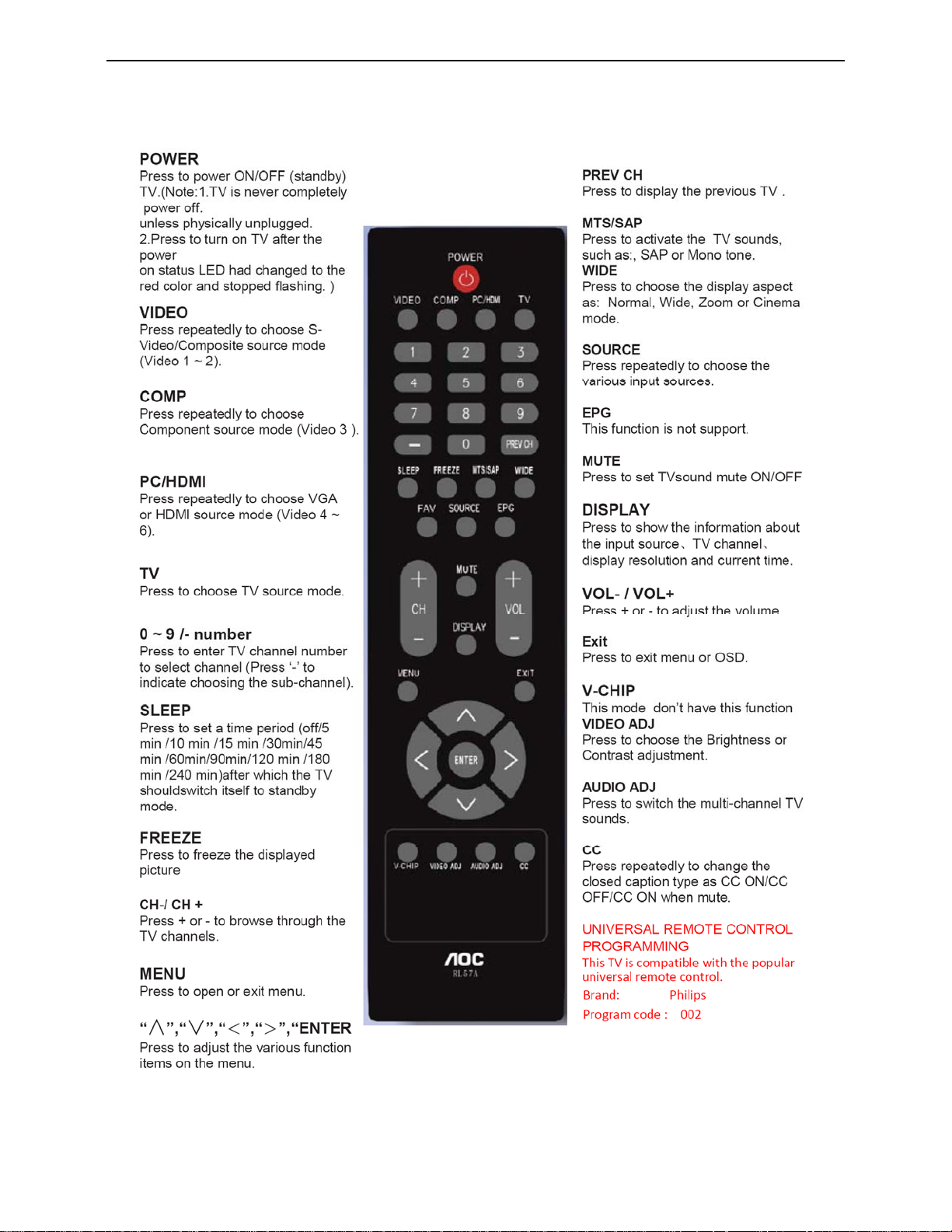
2.1 The Use of Remote Control
5
Page 6
32″LCD TV AOC L32W831
SETU
U
V
2.2 To Use the Menus
1. Press the MENU button to display the main menu
2. Use the cursor up/down to select a menu item.
3. Use the cursor left/right to enter a submenu.
4. Press the ENTER button to ena b l e/ d i s a bl e the function.
5. Press the MENU or EXIT button t o ex i t the men u.
Press the MENU button to enter the main OSD (On Screen Display). Adjust the items including Setup menu, Video
menu, Audio menu and Feature menu. However, some function items in the menus may only be enabled in the
particular source modes
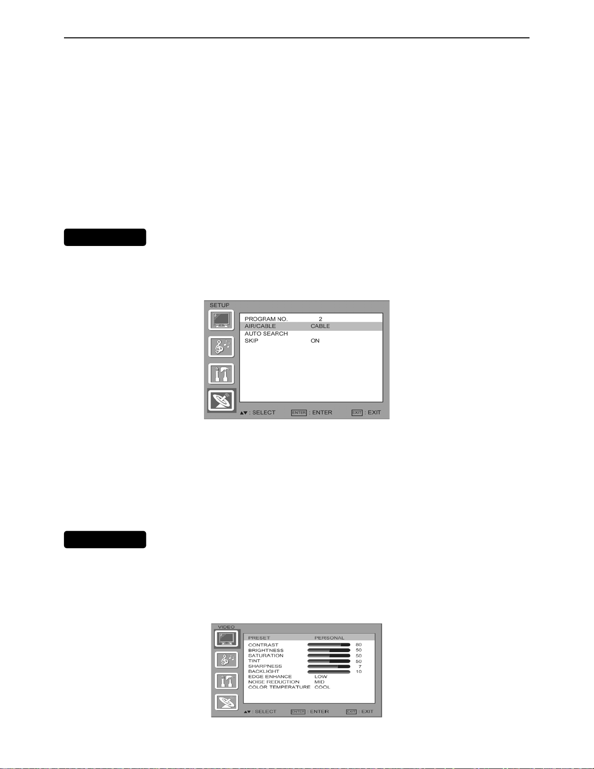
The Setup menu in TV mode shows as below. In others source modes, the Setup menu only shows Menu
Language and Aspect Ratio items.
P MEN
1. PROGRAM NO: Show the TV channel label menu for user modifying channel labels specifically.
2. AIR/ CABLE: Select TV source signal from the Air (antenna) or Cable (CATV).
3. AUTO SEARCH: Automatically scan all NTSC TV channels and then store in the channel table. In
channel scan process, the OSD can display the number of channels which had been found.
4. SKIP: you can select the ship ON/OFF,so that the program no channel can be delete or added.
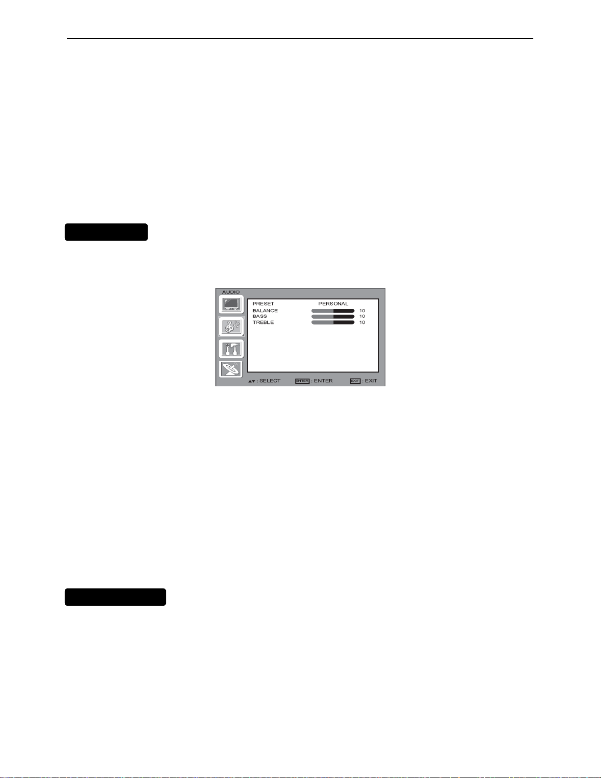
IDEO MENU
The Video menu in most source mod es shows as bel ow. It provides several video adjust ment items for user fine
tuning the video display. Only in VGA source modes, the Video menu simply provides Contrast, Brightness, Back
light and Settings (Preset) items.
6
Page 7
32″LCD TV AOC L32W831
U
If you selected PERSONAL, press or to highlight an option, then press or to adjust the option. You can adjust:
1. CONTRAST: Video contrast adjustment, the tuning range is 0 ~ 100.
2. BRIGHTNESS: Video brightness adjustment, the tuning range is 0 ~ 100.
3.SATURATION: COLOR saturation adjust, the tuning range is 0 ~ 100
4. TINT: Video tint adjustment, the tuning range is R50 ~ G50.
5. SHARPNESS: Video sharpness adjustment, the tuning range is 0~10
6. BACKLIGHT: Backlight strength adjustment, the tuning range is 0 ~ 10.
7. EDGE ENHANCE: Press < or > to select HIGH, OFF, or LOW.
8.NOISE REDUCTION: Press < or > to select HIGH .OFF, LOW or MID.
9.COLOR TEMPERATURE: Press < or > to select COOL, STANDARD, or WARM.
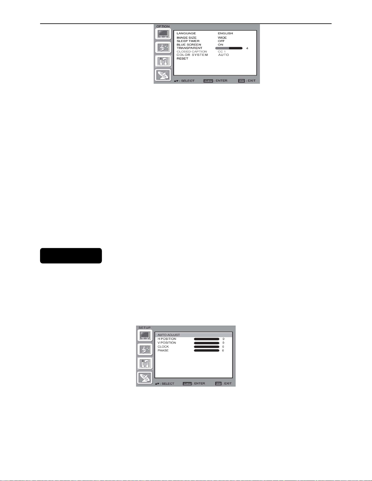
AUDIO MENU
The Audio menu in TV mode shows as below. It provides audio adjustment for user to modify the audio setting.
Audio language setting is only available with ATSC TV source, the option is disable under other source modes.
Press or to highlight AUDIO, then press > The AUDIO menu opens.
Press or to highlight PRESET, then press < or > to select an audio mode. You can select:
• VOICE
• MUSIC
• THEATER
• PERSONAL
If you selected PERSONAL, press or to highlight an option, then press or to adjust the option. You can
adjust:
• BALANCE—Adjust the balance between the right and left audio channels.
• BASS—Adjust the low sounds.
•TREBLE—Adjust the high sounds.
FEATURE MEN
The Feature menu in AV/S-video mode shows as below. It provides certain optional control functions such as image
size, sleep time r, blue screen on/off, trans parent, closed caption, col or system. This menu gives us ers the most
flexibilities to satisfy their generally demands. According to the various requirements in different source modes,
certain features should be hidden (disable) on the menu. The details footnotes will be described clearly below.
7
Page 8
32″LCD TV AOC L32W831
1. LANGUAGE: you can select the ENGLISH SPANISH Portuguese French
2. IMAGE SIZE : you can select WIDE, ZOOM, CINEMA, NORMAL
3. SLEEP TIMER: Enable or disable the TV standby timer. User can set the TV standby timer
/ 15 min/ 30 min / 45 min / 60 min/ 90 min / 120 min / 180min/ 240min. Timer starts to count down after cursor
leaving the sub-menu. (At the moment, the item shows 『** min Left』and the cursor highlights on the Feature
icon.)
4. BLUE SCREEN: you can select blue screen ON/OFF
5. TRANSPARENT: you can select from 0 to 7
6. CLOSED CAPTION:Press or to highlight CLOSED CAPTION, then press or to select the closed captioning
mode. You can select CC1.CC2, CC3, CC4, TT1, TT2, TT3 or TT4.
7. COLOR SYSTEM: this function you select color system.default is auto you can choose NTSC, PAL M, PAL N.
8. RESET: you can use it reset all setting to default.
VGA SETTING MENU
VGA Set: This option only shows and is avail able in VGA mode, which pr ovides several it ems for the V GA display
as off / 5 min / 10 min
fine tuning, such as : 【H-Position】、【V-Position】、【Clock】and 【Phase】. All th ese items giving the tuning range
from 0 to 100.【Setting】item provides the default VGA setting values restoring.
8
Page 9
32″LCD TV AOC L32W831
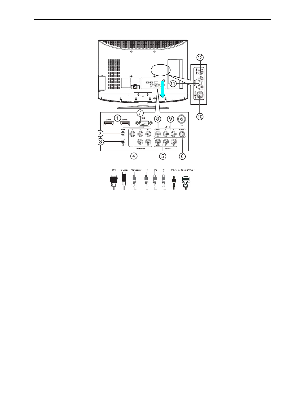
2.3 How to Connect
1. HDMI – Connect the primary source for digital video such as a DVD multimedia player or set top box
through this all digital connector. The white color band on the rear of the TV indicates this connection.
2. VGA AUDIO– Connect the audio for a computer to this jack.
3. HEADPHONE – Connect headphone to this jack.
4. COMPONENT (YPb/CbPr/Cr with Audio L/R) – Connect the primary source for component video
devices such as a DVD Player or set top box here. From left to right, use red for Pr, blue for Pb, green
for Y, red for right audio (R) and white for left audio (L) inputs.
5. AV OUT– Connect a VCR for recording to these jacks
6. S-VIDEO1 – Connect an S-Video device to this jack.
7. RGB PC – Connect the video and audio cables from a computer here.
8. AV1 IN – Connect the primary source for composite video devices, such as a VCR or video game.
9. Use the white and red connectors to connect the external audio from the same source. The signal
being carried by the S-Video cable and connector, if connected, will take priority over the Video RCA
connector (yellow connector).
10. S-VIDEO2 – Connect an S-Video device to this jack.
11. Use the white and red connectors to connect the external audio from the same source. The signal
being carried by the S-Video cable and connector, if connected, will take priority over the Video RCA
connector (yellow connector)
12. AV2 IN – Connect the primary source for composite video devices, such as a VCR or video game.
Once your equipment is connected, use the following procedure to view the input signal:
9
Page 10
32″LCD TV AOC L32W831
Press the source button on the remote controller to select the relevant source to view. (ex: Press VIDEO button to
select “Composite Rear” if you have connected a video recorder to Composite Rear socket.)
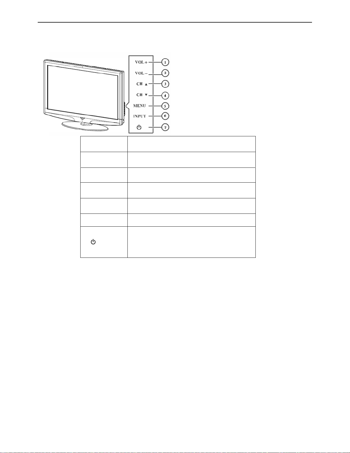
2.4 Front Panel Control Knobs
1 VOL▲
2 VOL▼
3 CH ▲
4 CH ▼
5 MENU
6 INPUT
VOL +: Press to increase the sound volume level.
VOL - : Press to decrease the sound volume level.
CH +: Press to select the next higher Program
number.
CH - : Press to select the next lower Program
number.
Menu key: Press
to open or exit the OSD menu.
Source key: Press to select the input source.
Power key: Press to turn on / off (standby) the TV
set.
7
(Please re-turn on TV after the Power-ON status
LED had changed to the Red color and finished
flashing.)
10
Page 11
32″LCD TV AOC L32W831
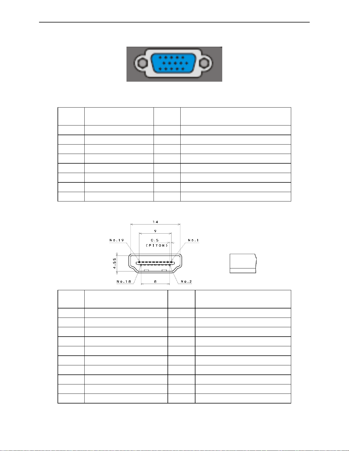
3. Input/Output Specification
3.1 RGB Signal input
15 - Pin Color Display Signal Cable
Pin No. Description Pin No. Description
1 Red Video 9 No Pin
2 Green Video 10 Sync Ground
3 Blue Video 11 SDA(Remote Control)
4 SCL(Remote Control) 12 Serial Data for DDC
5 Ground 13 H-Sync.
6 Red Ground 14 V-Sync.
7 Green Ground 15 Serial Clock for DDC
8 Blue Ground
3.2 HDMI Digital connector pin assignments
Pin No. Description Pin No. Description
1 TMDS Data2+ 2 TMDS Data2 Shield
3 TMDS Data2- 4 TMDS Data1+
5 TMDS Data1 Shield 6 TMDS Data1-
7 TMDS Data0+ 8 TMDS Data0 Shield
9 TMDS Data0- 10 TMDS Clock+
11 TMDS Clock Shield 12 TMDS Clock13 CEC 14 NC
15 SCL 16 SDA
17 DDC/CEC Ground 18 +5V Power
19 Hot Plug Detect
11
Page 12
32″LCD TV AOC L32W831
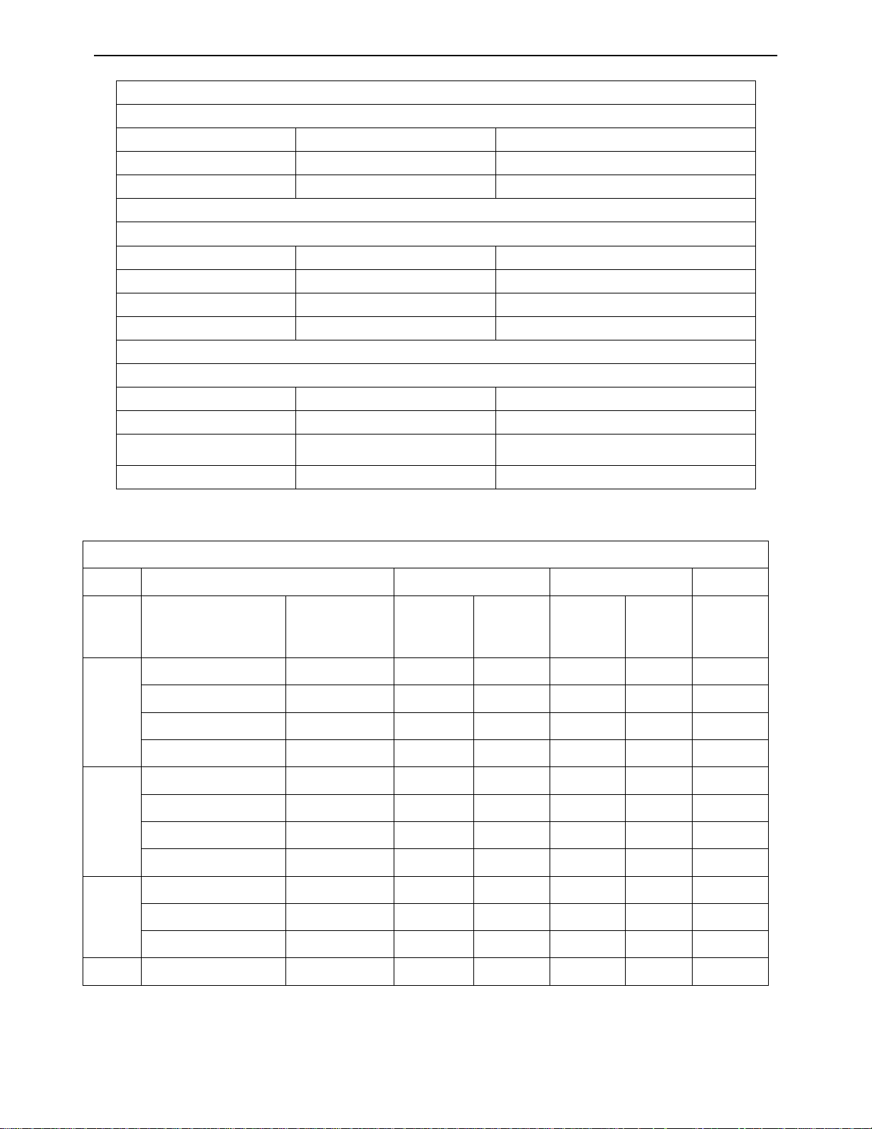
3.3 AV/S-Video/Component Video Inputs
AV (Composite Video input)
Video1/2
Amplitude 1.0 V (p-p), negative sync.
Impedance 75 ohm terminated
S-Video (Y / C input)
S-Video1/2
System NTSC / PAL-M / PAL-N
Y signal amplitude 1.0Vpp (including sync)
C signal amplitude 0.286Vpp
Impedance 75 ohm terminated
Component (Y, Pb/Cb, Pr/Cr input)
Video1
Y signal amplitude 1.0Vpp (including sync)
Impedance 75 ohm terminated
Cr, (R-Y) / Cb, (B-Y)
System NTSC / PAL-M / PAL-N
System 1080i, 480p, 720p, 480i
Signal amplitude
±0.35Vpp, 75 ohm
3.4 Compatible Mode Table
VESA MODES
Horizontal Vertical
Nominal
Pixel
Clock
(MHz)
Mode Resolution Total
640x480@60Hz 800 x 525 31.469 N 59.940 N 25.175
VGA
SVGA
XGA
640x480@72Hz 832 x 520 37.861 N 72.809 N 31.500
640x480@75Hz 840 x 500 37.5 N 75 N 31.500
720x400@70Hz 900 x 449 31.469 N 70.087 P 28.322
800x600@56Hz 1024 x 625 35.156 P 56.25 P 36.000
800x600@60Hz 1056 x 628 37.879 P 60.317 P 40.000
800x600@72Hz 1040 x 666 48.097 P 72.188 P 40.000
800x600@75Hz 1056 x 625 46.875 P 75 P 49.5
1024x768@60Hz 1344x806 48.363 N 60.004 N 65.000
1024x768@70Hz 1328x806 56.476 N 70.069 N 75.000
Nominal
Frequency
(KHz)
Sync
Polarity
Nominal
Freq.
(Hz)
Sync
Polarity
1024x768@75Hz 1312x800 60.023 P 75.029 P 78.750
WXGA 1360x768@60Hz 1792X795 47,712 P 60.015 P 85.5
12
Page 13
32″LCD TV AOC L32W831
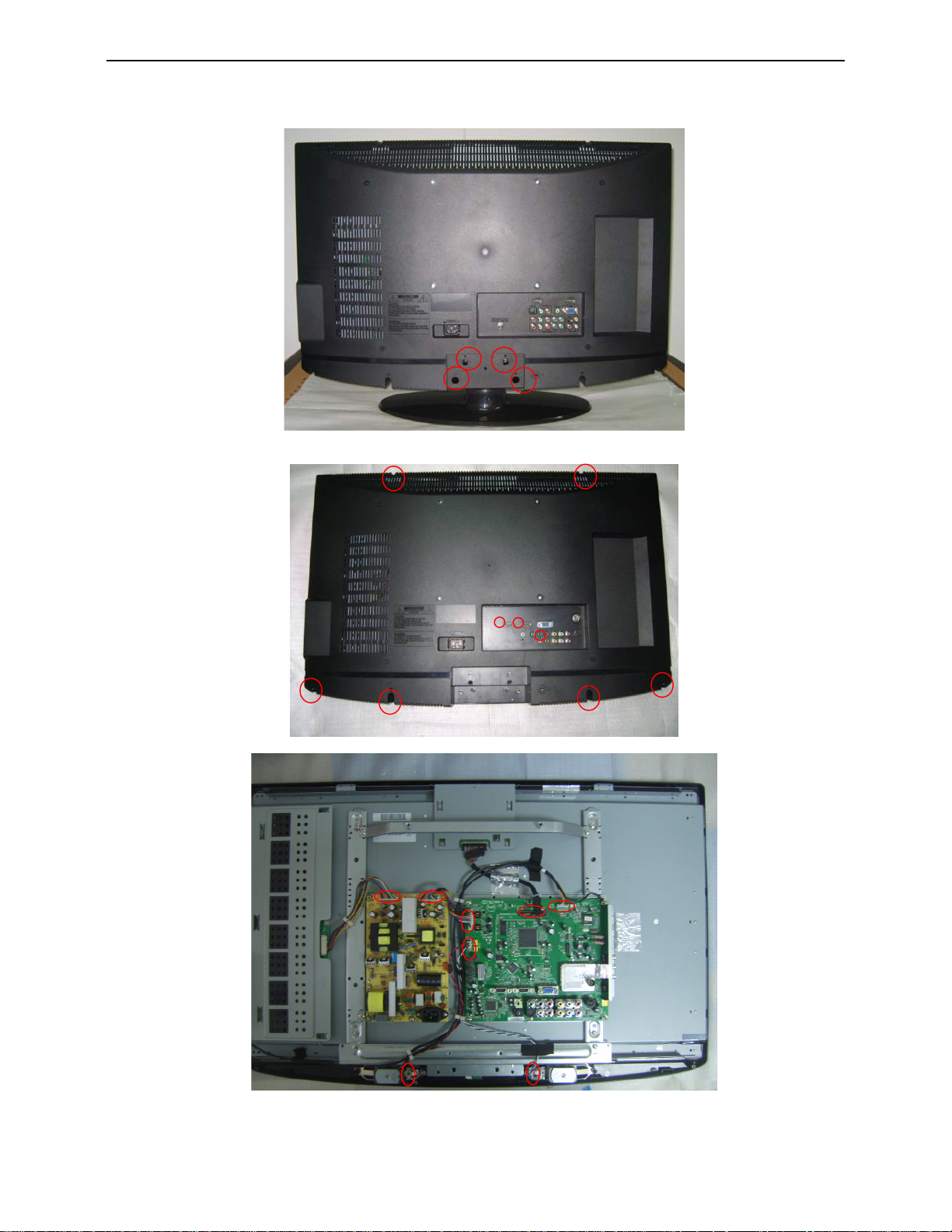
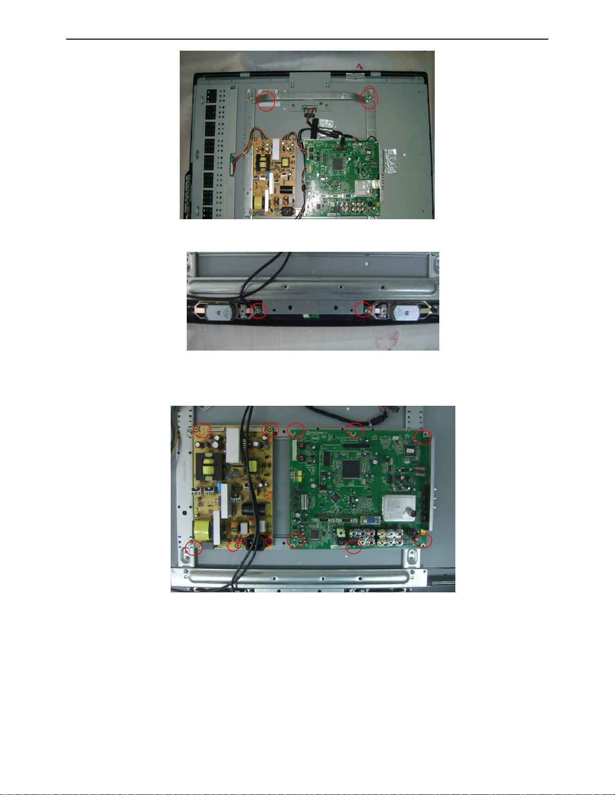
4. Mechanical Instructions
1. Remove the 4 screws to remove the base.
2. Remove 9 screws to remove the rear cover.
3. Release the connectors
13
Page 14
32″LCD TV AOC L32W831
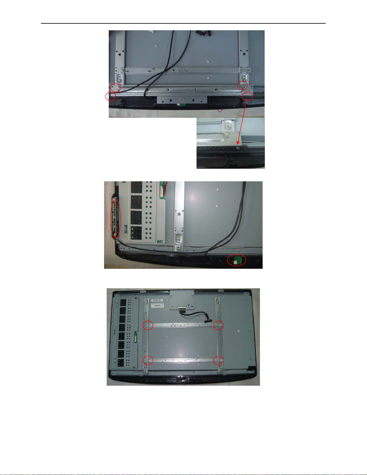
4. Remove 2 screws to remove the bkt-vesa-top.
5.Remove 2 screws to remove the speakers
6. Remove the main board, power board.
14
Page 15
32″LCD TV AOC L32W831
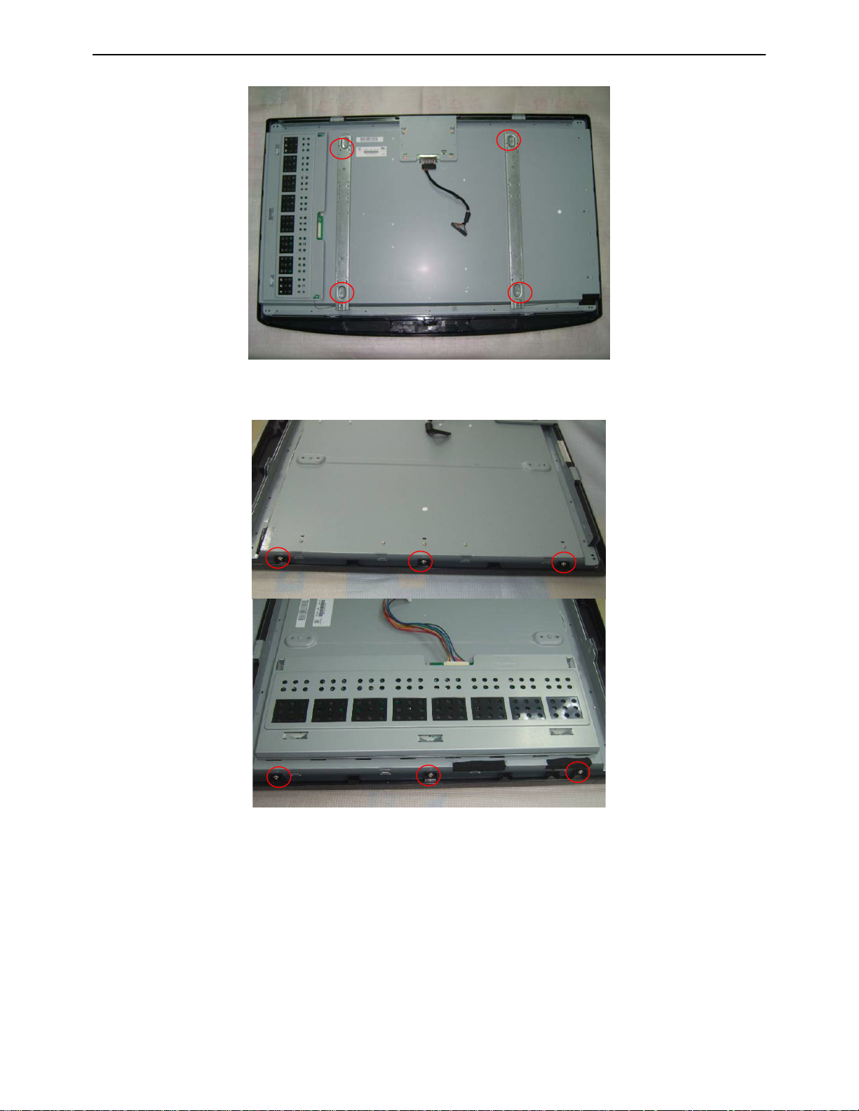
7. Remove the bkt-base-support..
7. Release the key board and IR board.
8. Remove the bkt-pcb-holder.
15
Page 16
32″LCD TV AOC L32W831
9. Remove the bkt-panel-support.
10. Remove the bezel.
16
Page 17
32″LCD TV AOC L32W831
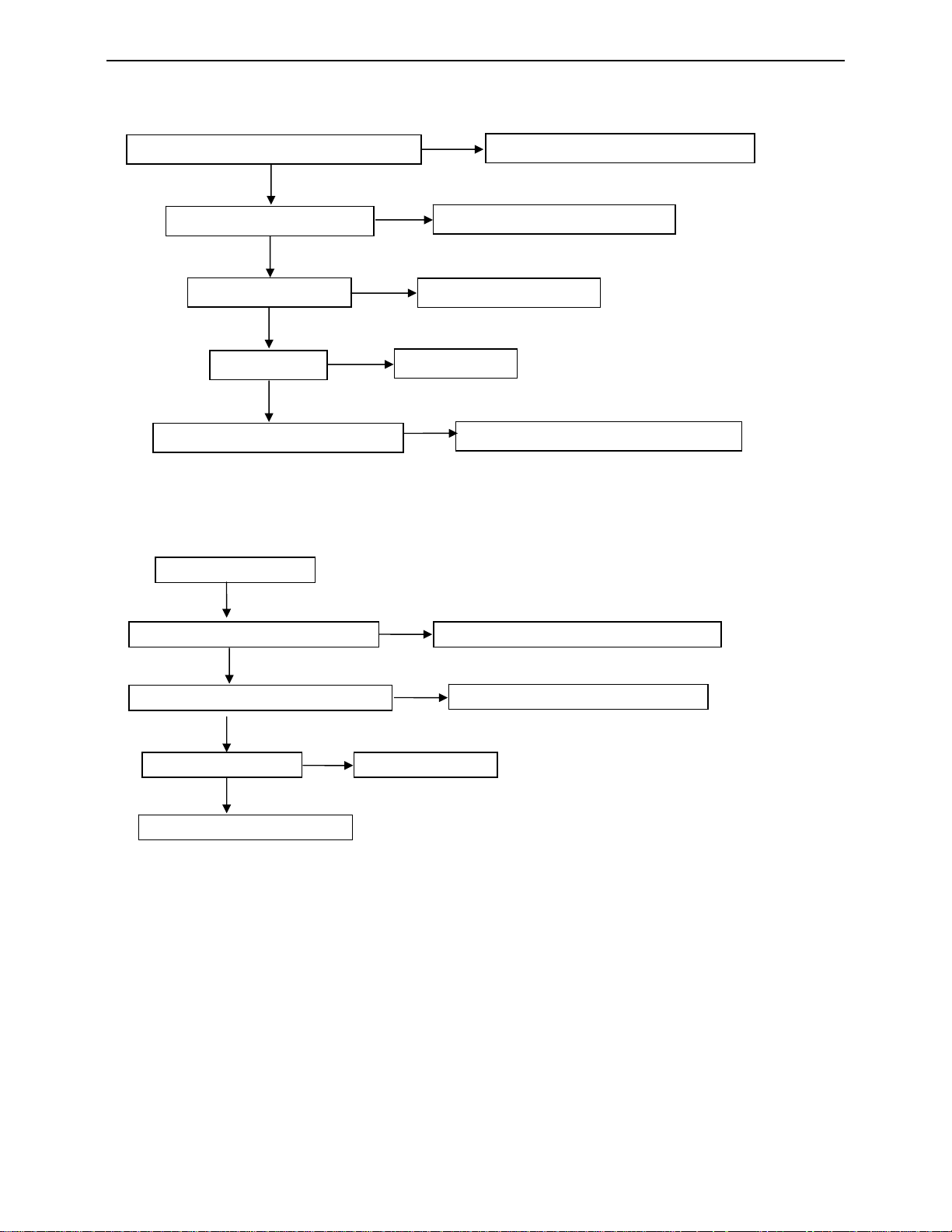
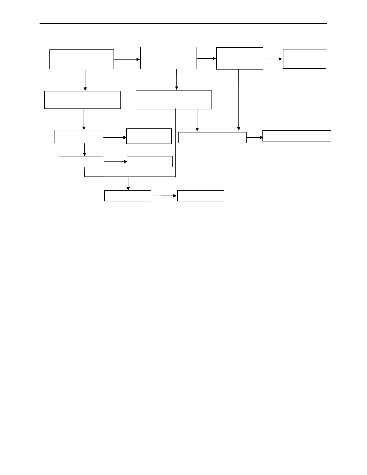
5. Repair Flow Chart
1. No Power (No LED indicator)
Check power cord and board interface
OK
Check F901, BD901
OK
Check D902, C920
OK
Check T901
OK
Check D937, C952, C953,D932
NG
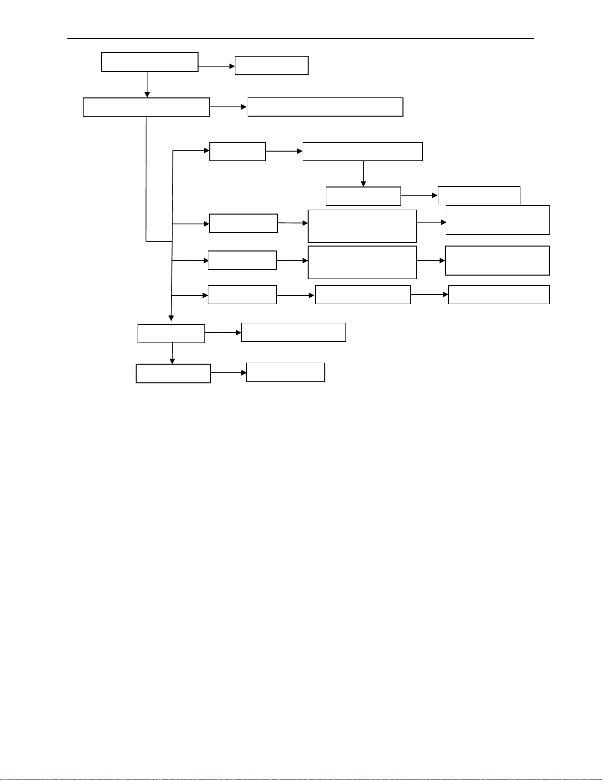
2. Can not start (No LED indicator)
Can not start
NG
NG
Replace T901
NG
NG
Replace F901 or BD901
Replace D902 or C920
Plug in power cord and interface
Replace D937 or C952 or C953 or D932
OK
Check key board or remote control
OK
Check power supply for main board
OK
Check U403
OK
Check I2C communication
NG
NG
Replace U403
Repair key board or remote con t r ol
NG
Replace the failure component
17
Page 18
32″LCD TV AOC L32W831
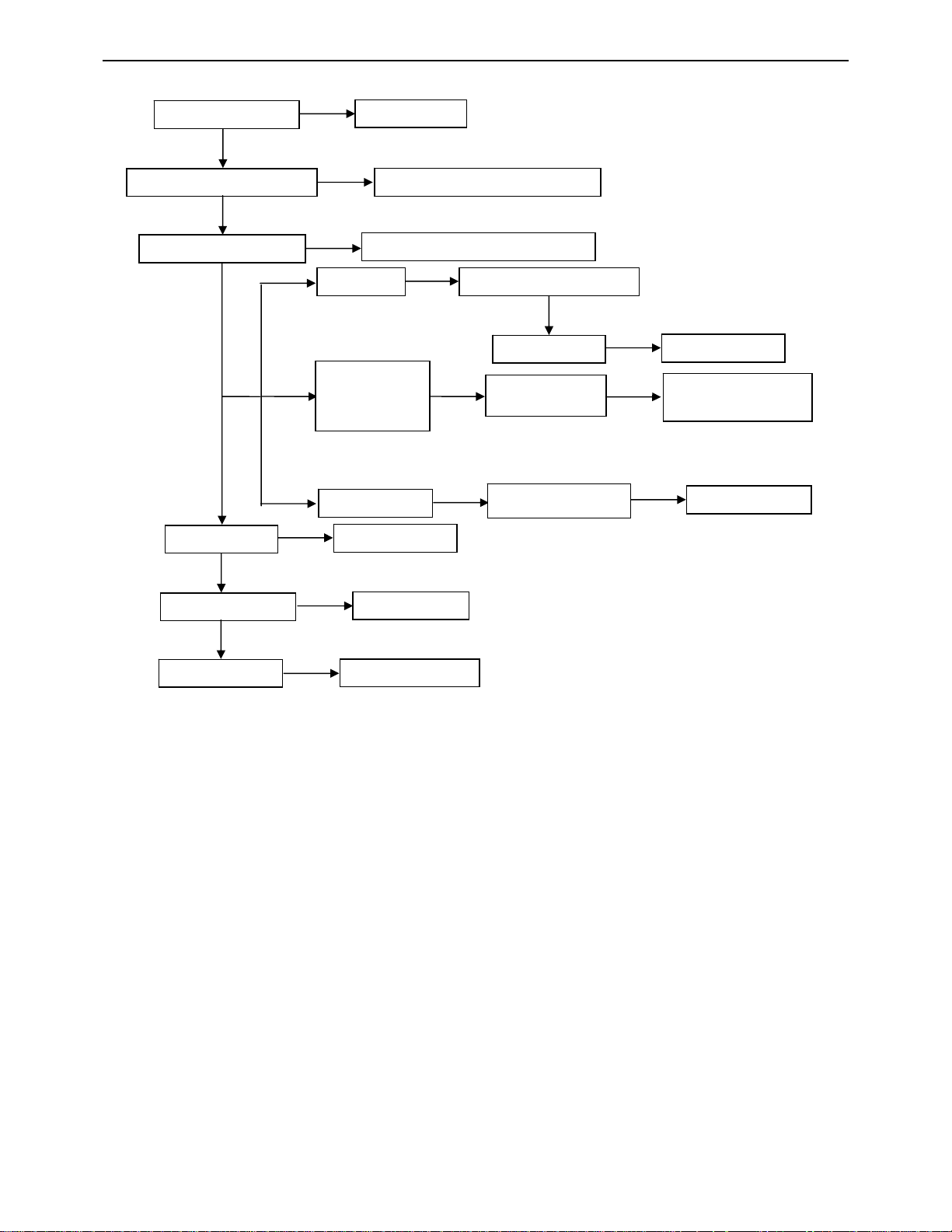
3. No display (LED indicator Green )
Check back light is OK
OK
Check LVDS cable
and connector
OK
Check U403
OK
Check U401
NG
NG
NG
Check Panel
Replace U403
Replace U401
OK
Check 12V
power supply
OK
Check BL-ON/OFF signal
NG
Replace Panel
NG
NG
Check PS
signal
NG
NG
OK
Check power
board
18
Page 19
32″LCD TV AOC L32W831
4. Abnormal display
Check the source
OK
NG
Reset source
Check signal filter circuit
OK
OK
Check U401
OK
Check panel
NG
TV signal Check TV system setup
AV/SV signal
PC signal
HDMI signal Check U507 Replace U507
NG
NG
Replace the filter or inductance
OK
Check TU701
Check the circuit from
connector to U401
Check the circuit from
connector to U401
Replace U401
Replace panel
NG
Replace TU701
NG
NG
NG
Replace the failure
component
Replace the fa i lure
component
19
Page 20
32″LCD TV AOC L32W831
p
5. No sound
Check the source
OK
Reset source
Check signal filter circuit
Check Earphone jack
OK
Check U603
Check U606
NG
NG
NG
SIF signal Check TV system setu
AV/SV/COMP
ONENT/PC
signal
HDMI signal
NG
Replace the filter or inductance
Replace the Earphone jack
NG
NG
Replace U6 03
Replace U606
OK
Check TU701
Check U603
Check U507
NG
NG
Replace TU701
Replace the failure
component
NG
Replace U507
OK
Check speaker
NG
Replace speaker
20
Page 21
32″LCD TV AOC L32W831
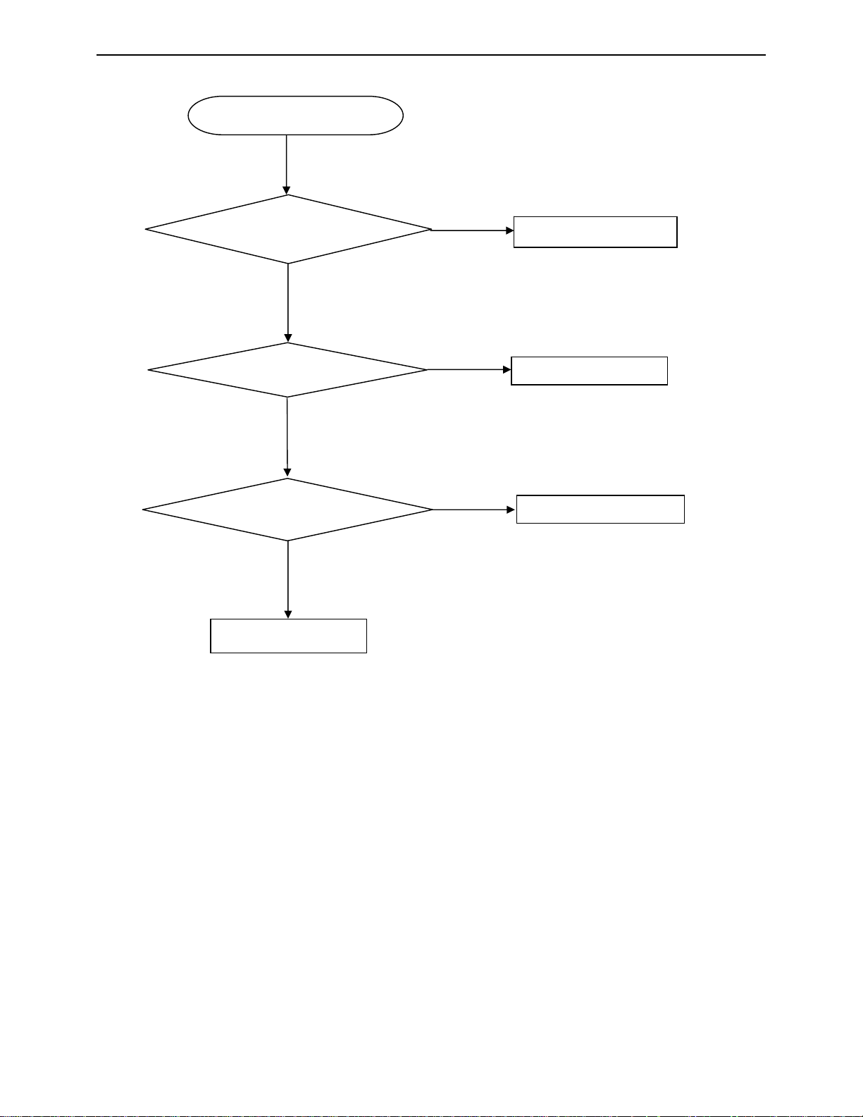
6. Key Board
OSD is unstable or not working
Is Key Pad Board connecting normally?
Y
Is Button Switch normally?
Y
Is Key Pad Board Normally?
Y
Check Main Board
N
N
N
Connect Key Pad Board
Replace Button Switch
Replace Key Pad Board
21
Page 22

32″LCD TV AOC L32W831
6. PCB Layout
6.1 Main Board
22
Page 23

32″LCD TV AOC L32W831
23
Page 24

32″LCD TV AOC L32W831
24
Page 25

32″LCD TV AOC L32W831
6.2 Power Board
25
Page 26

32″LCD TV AOC L32W831
6.3 Key Board
6.4 IR Board
26
Page 27

32″LCD TV AOC L32W831
7. White Balance, Luminance Adjustment
Approximately 2 hours should be allowed for warm up before proceeding white balance adjustment.
Before started adjust white balance, please set the Ca210 Channel to 05 Channel and set it’s mode to xyLv mode.
Color Temp. Cold Normal Warm
PC/HDMI/AV
/YpbPr
How to setting the Ca210 channel, you can reference to Ca210 user guide or simple use the “Memory CH” up or
down to set the channel to 05 channel, and use the “Mode” key to set the mode to xyLv.
Following is the procedure to do white-balance adjust
Factory mode:
. Turn on the TV, press MENU key with remote control, then press number key 1 Æ 9 Æ 9 Æ 9. It will
achieve the factory mode. Select the item of White Balance and press right key to enter it.
. Select “source” like PC/AV/YPbPr/HDMI, then select “color temp” to adjust the corresponding R/G/B
values.
Note:
1. set the input signal format of PC as 1024x768 @60 Hz, AV as NTSC system, YPbPr as 576I, HDMI as 1080I
2. before adjusting all color temp, make PC and YPbPr auto color first.
3. the model usually needn’t to be adjusted W/B, only to make auto color.
x 285 295 313
y 293 305 329
LV Panel max luminance
27
Page 28

32″LCD TV AOC L32W831
p
p
A
A
8. Block Diagram
PP-SCL &SDA
PC
74HC4052D
IIC SWITCH
U103
ISP-SCL & SDA
MCU
NT68F631
U403
SCL_T&SDA_T
RGB
HDMI1
HDMI2
COMPONENT
AV1
AV2
SV1
SV2
LR
JACK
AV1
AV2
Com
PC Audio
AV1 Audio
AV2 Audio
Y Pb Pr
AV1 C V BS
AV2 C V BS
SV1 Y C
SV2 Y C
onent
PS321
U507
HDCP
U509
SCL&SD
EEPROM
U404
DSCL& DSDA
KSCL& KSDA
AUDIO
DECODER
U603
LINE OUT
HP R&L
MX25L40
05AMC
U510
VIDEO
DECODER
&
SCALER
NT7263
U401
CVBS
mplifier
U606
PT2308
U605
TDA9885
U708
CVBS OUT
SIF
SIF
SPEAKE
Ear
AF38A7DC
hon
MVF38A2
TUNER
Panel
28
Page 29

32″LCD TV AOC L32W831
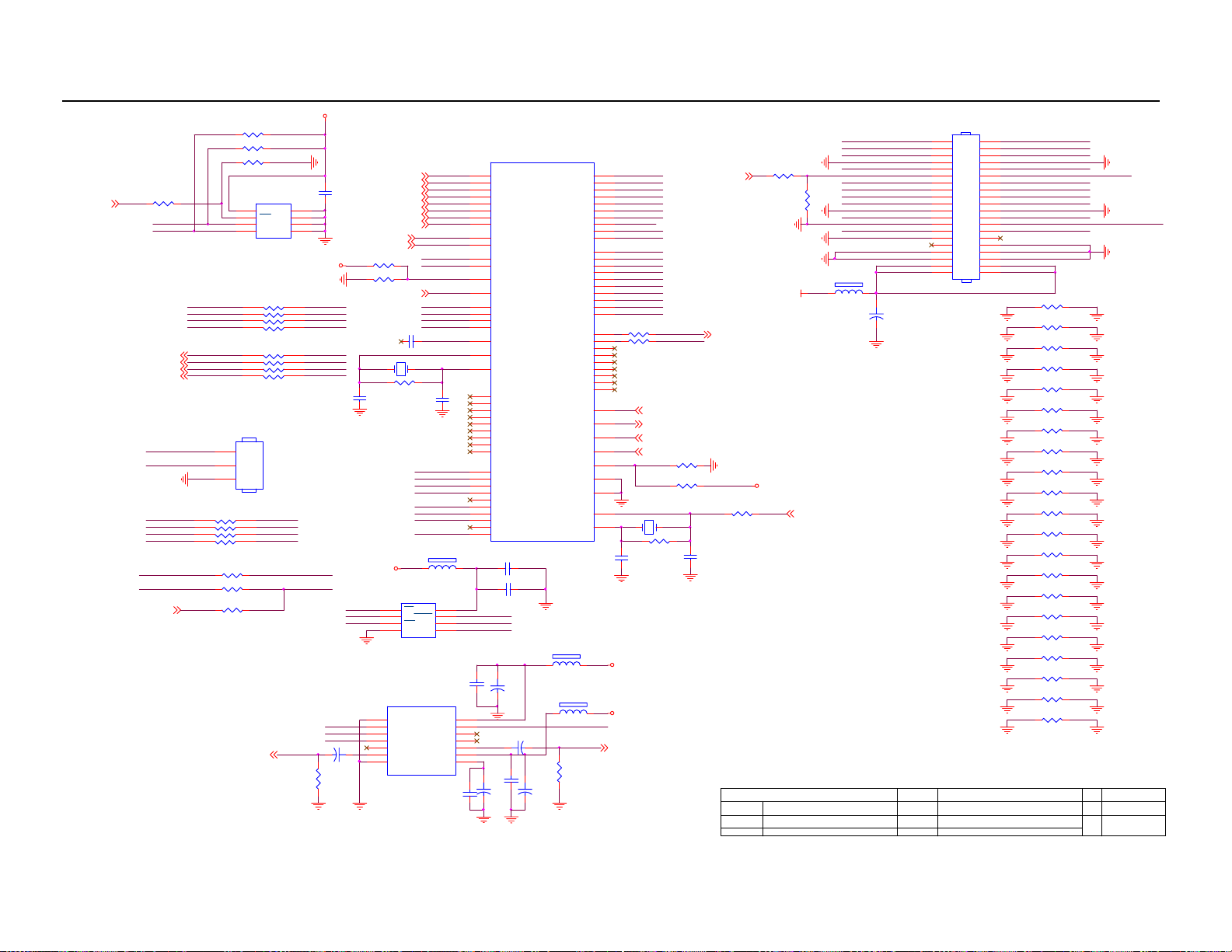
9. Schematic Diagram
9.1 Main Board
MAIN 5V
INT_IR7
5VP
MCU_VCC
5VP
ADC07
1
2
3
4
5
6
7
8
9
10
11
12
CONN
CN702
C766
0.1uF
(5V STAND BY)
680 OHM 1/10WR701
0 OHM 1/10WR702
R703 NC
100 OHM 1/10WR704
MAIN5V
(5V STAND BY)
+5VP
150 OHML701
1
8
2
7
3
6
45
300 OHM
LP701
0.1uF C704
0.1uF C703
0.1uF C702
BL
600 OHML702
BL_BRI
600 OHML703
+12VP
C706
24VP
0.1uF
C707
0.1uF
24VP MAIN 5V
R785
NC
Q711
R787
NC
NC
0.1uF C705
BACKLIGHT5
L724
300 OHM
MAIN24V
Q709
NC
1
8
D
S
2
7
D
S
3
6
D
S
4
5
D
G
R786
NC
100pF C701
R705
47K OHM 1/10W
+12VP
CN701
1
2
3
4
5
6
7
8
BRIGHTNESS7
CONN
BL
C714
0.1uF
L704
NC/L
5
4
L725
300 OHM
47K OHM 1/10W
TP701
1
3
C719
0.1uF
MMBT3904
R709
TP702
12VP
R713
47K OHM 1/10W
Q702
MMBT3904
MAIN 5V
Q704
TP703
R714
22K OHM 1/10W
R710
1K OHM 1/10W
R711
10K OHM 1/10W
R712
10K OHM 1/10W
TP704
PANEL_ON7
Q701
AO4411
1
S
2
S
3
S
4
G
10K OHM 1/10W
TP705
BL_BRI
C715
22UF/10V
L712 NC
12VP
R720
10K OHM 1/10W
(for panel T1,T2 )
R721
100K OHM 1/10W
+5VP
Q710
MMBT3904
Q705
MMBT3904
5
4
L726
300 OHM
R718
22K OHM 1/10W
R784
22K OHM 1/10W
R722
22K OHM 1/10W
MAIN12V
8
D
7
D
6
D
5
D
R715
5VP
R783
10K OHM 1/10W
R788
NC
L706
NC/L
300 OHML705
1 2
C721
0.068uF
1
3
C720
0.1uF
POWER_ON 7
5VP
R716
47K OHM 1/10W
0 OHM 1/10W
Q707
MMBT3904
1
2
3
4
R717
5VP
Q706
AO4411
5V:1200mA
8
7
6
5
R723
10K OHM 1/10W
D
D
D
D
8
7
6
5
PANEL_VCC
R719
3.3K OHM 1/10W
S
S
S
G
D
D
D
D
Q708
AO4411
1
S
2
S
3
S
4
G
C774 NC
C775
NC
MAIN12V
C722
0.1uF
+
C723
10uF/50V
U704
AZ1117H-ADJ-E1
3
VIN
1
ADJ
2
VOUT
R724
120 OHM 1/10W
R725
620 OHM 1/8W
U703
MAIN 5V
C711
U705
AIC1084-25PETR-R
3 2
VIN VOUT
+
+8V
+
C724
C725
10uF/50V
0.1uF
100uF/16V
MAIN 2V5
200mA
C712
0.1uF
+
C713
220uF/10V
GND
1
MAIN5V
100uF/16V
C708
U701
3 2
VIN VOUT
+
GND
1
Key Component
MAIN 3V3
900mA
+
C710
C709
220uF/10V
0.1uF
T P V ( Top Victory Electronics Co . , Ltd. )
T2968-B
01 POWER
Date
AP1084D18LA
ADJ(GND)
VOUT
VIN
MAIN1V 8
600mA
MAIN3V 3
123
C717
+
+
C716
100uF/16V
OEM MODEL Size
TPV MODEL
PCB NAME
Sheet
715T2968
110Thursday , J a nuary 31, 2008
0.1uF
C718
220uF/10V
of
A3
C
Rev
<>
29
Page 30

32″LCD TV AOC L32W831
HS
R106
2.2K OHM 1/10W
VGA_EDID7
75 OHM 1/10W
R103 510 OHM 1/10W
R104 510 OHM 1/10W
VS
ZD127
RLZ6.8B
1 2
R107
MCU_VCC
C197
NC
ISP_SCL
ISP_SDA
VPORT0603100KV05
CN102
PHONEJAC K
S1_C3
S1_Y3
R132
MCU_RX7
PP_SDA
PP_SCL
ZD126
C195
10pF
RLZ6.8B
1 2
2.2K OHM 1/10W
NC
NC
R195
R194
R196
18K OHM 1/10W
ZD106
12
VPORT0603100KV05
ZD107
12
3
2
1
C117
0.001uF
L108 120 OHM
L109 120 OHM
R133
75 OHM 1/10W
ZD101 VPOR T0603100KV05
12
ZD102 VPORT0603100KV05
12
R101 100 OHM 1/10W
R102 100 OHM 1/10W
L128 60 OHM
R105 100 OHM 1/10W
C196
10pF
C198
0.22uF
U102
8
A0
VCC
7
A1
WP
6
A2
SCL
GNDSDA
M24C02-WMN6TP
L104 150 OHM
L105 150 OHM
C118
0.001uF
C127
68pF
ZD108
C128
68pF
1 2
ZD103
12
1
2
3
45
SDA4, 5,7
ISP_SDA7
PP_SDA
SCL4,5,7
ISP_SCL7
PP_SCL
PC_R
PC_L
R192
NC
VPORT0603100KV05
VPORT0603100KV05
R163
R164
ISP_SW7
R193
ZD109
1 2
VPORT0603100KV05
11
12
13
14
15
MCU _VCC
NC
NC
5VP
PC_R 9
PC_L 9
NC
4 5
2 3
CN103 DIN JACK
CN101
1716
DB15
1
6
2
7
3
8
4
9
5
10
R130 0 OHM 1/10W
R131 0 OHM 1/10W
C168
0.1uF
U103
74HC4052D
12
X0
14
X1
15
X2
11
X3
1
Y0
5
Y1
2
Y2
4
Y3
10
A
9
B
6
EN
7
VEE
16
VDD
1
6
R108 100 OHM 1/10W
D105
LL4148
12
12
ZD105
ZD104
VPORT0603100KV05
VPORT0603100KV05
1 2
HS
3 4
5 6
9 8
11 10
VS
13 12
PP_SDA
13
X
PP_SCL
3
Y
GND
8
S2_C3
S2_Y3
R189
75 OHM 1/10W
MCU _TX 7
VGA
U101
1A 1Y
2A 2Y
3A 3Y
4A 4Y
5A 5Y
6A 6Y
714
GNDVCC
74LVC14ADT
ISP_SDA7
ISP_SCL7
CVBS_OUT3
AV1_CVBS3
75 OHM 1/10W
L125 120 OHM
L126 120 OHM
R190
75 OHM 1/10W
Q107
2SD1757K
ZD121
1 2
of
ZD115
VPORT0603100KV05
ZD116
VPORT0603100KV05
ZD117
VPORT0603100KV05
R181
680 OHM 1/10W
R182
680 OHM 1/10W
Q106
2SD1757K
R188
47K OHM 1/10W
325
ZD120
1 2
VPORT0603100KV05
VPORT0603100KV05
L115 120 OHM
C136
68pF
1 2
L116 120 OHM
C137
68pF
1 2
L117 120 OHM
C138
68pF
1 2
4.7K OHM 1/10W
R186
47K OHM 1/10W
4.7K OHM 1/10W
L120
L121
C141
C142
220pF
220pF
D103
1
D104
BAV99
3
2
L101 32 OHM
L102 32 OHM
L103 32 OHML127 60 OHM
C1925.6pF
C1945.6pF
C1935.6pF
R170
R171
100 OHM 1/10W
100 OHM 1/10W
L110
120 OHM
VPORT0603100KV05
R191
0 OHM 1/10W
R141
C188
C187
68pF
68pF
ZD124
ZD125
1 2
1 2
VPORT0603100KV05
R11175 OHM 1% 1/ 10W
I0_HS 3
MCU_HS 7
MCU _VS 7
I0_VS 3
12
ZD110
L119 120 OHM
VPORT0603100KV05
I0_R 3
I0_G 3
I0_B 3
R11075 OHM 1% 1/ 10W
R10975 OHM 1% 1/ 10W
3
1
CN106
JACK
32659814
C129
68pF
ZD119
1 2
VPORT0603100KV05
CN108
4
2
6
DIN JACK
1
BAV99
3
2
5VP
L113
HD_L
HD_L9
D106
BAV99
2
C140
68pF
L114
5VP
HD_R
HD_R9
ZD111
ZD112
7
1 2
VPORT0603100KV05
C143
ZD122
ZD123
220pF
1 2
1 2
VPORT0603100KV05
VPORT0603100KV05
3
1
5
AV2_CVBS3
75 OHM 1/10W
T P V ( Top Victory Electronics Co . , Ltd. )
Key Component
Date
5VP
600 OHM
R134
NC
600 OHM
R135
NC
C132
470pF
1 2
VPORT0603100KV05
L123 600 OHM
L124 600 OHM
C144
220pF
R139
T2968-B
02 INPUT / OUTPUT
ZD113
1 2
VPORT0603100KV05
ZD114
1 2
VPORT0603100KV05
600 OHM
600 OHM
C133
470pF
R144
NC
R140
0 OHM 1/10W
CN105
JACK
1
2
5
6
9
C134
220pF
C135
220pF
L111
L112
L118 120 OHM
10
3
4
7
8
C130
4.7uF/16V
C131
4.7uF/16V
R184
R183
100K OHM 1/10W
100K OHM 1/10W
AV1_R
AV1_R 9
AV1_L
AV1_L 9
R145
NC
CN111
JACK
79461
8
C139
ZD118
68pF
1 2
VPORT0603100KV05
OEM MODEL S i ze
TPV MODEL
715T2968
PCB NAME
Sheet
210Thursday, J anuary 31, 2008
C181
4.7uF/16V
C182
4.7uF/16V
R187
600 OHM
600 OHM
LINEOUT_L
LINEOUT_R
R185
R136
75 OHM 1/10W
R137
75 OHM 1/10W
R138
75 OHM 1/10W
LIN EOUT_ MUTE 7 ,9
R142
R143
NC
HD_Y 3
HD_PB 3
HD_PR 3
LINEOUT_L 9
LINEOUT_R 9
AV2_L
AV2_R
NC
Rev
AV2_L 9
AV2_R 9
< >
A3
C
30
Page 31

32″LCD TV AOC L32W831
C769
0.0015uF
+5VIF
+
L722 200uH
U106
MC34063A
1
SWC
2
SWE
3 6
TCAP VCC
4
GND
R776
150 OHM 1/10W
I0_R2
I0_G2
I0_B2
HD_PR2
HD_Y2
HD_PB2
IF
IF_SW7
C755
0.01uF
180 OHM 1/10W
DC
PK
COMP
R777
1.8K OHM 1/10W
R146
100 OHM 1/10W
R147
R148
100 OHM 1/10W
R149
100 OHM 1/10W
R150
100 OHM 1/10W
R151
100 OHM 1/10W
R152
I0_HS2
I0_VS2
100 OHM 1/10W
R155
100 OHM 1/10W
R156
100 OHM 1/10W
R157
100 OHM 1/10W
R158
100 OHM 1/10W
R159
100 OHM 1/10W
R160
100 OHM 1/10W
R161
D702 NC
R781
NC
L720
120 OHM
31
R778
8
7
5
C770
0.1uF
100 OHM 1/10W
100 OHM 1/10W
NC
R780
R779
6R2 1/4W 5%
1 2
L721 300 OHM
+
C771
100uF/16V
C145 0.047uF
C146 0.047uF
C147 0.047uF
C148 0.047uF
C149 0.047uF
C150 0.047uF
C151 0.047uF
R153 100 OHM 1/10W
R154 100 OHM 1/10W
C152 0.047uF
C153 0.047uF
C154 0.047uF
C155 0.0047uF
C156 0.047uF
C157 0.047uF
C158 0.047uF
C159 NC
+5VT
+5VT
I0R0+
I0G0+
I0SOG0
I0B0+
I0R1+
I0G1+
I0SOG1
I0B1+
C160 0.1uF
C161
0.1uF
SW
Q506
NC
Key Component
MAIN12V
57
65
66
69
70
VIF-
SIF+
VIF+
255
I0R0+
256
I0R0-
253
I0G0+
252
I0SOG0
254
I0G0-
250
I0B0+
251
I0B0-
1
I0HS0
2
I0VS0
245
I0R1+
246
I0R1-
243
I0G1+
242
I0SOG1
244
I0G1-
240
I0B1+
241
I0B1-
247
I0RMDSCV
239
I0BMDSCV
U401C
NT7263
C162 0.1uF
C163 0.1uF
C164 0.1uF
C165 0.1uF
T P V ( Top Victory Electronics Co . , Ltd. )
T2968-B
03 TUNER / IF , IO / I1
Date
73
SIF-
PEAK
VAFC
I0/I1 Block
I1ADC1-
I1VSOUT
I1ADC2-
I1ADC3-
I1ADC0-
40
26
35
31
44
22 OHM 1/10W
54
59
64
71
VPLL
FMPLL
TAGC
SSIF
MONO
IFY_OUT
I1Y0
I1Y1
I1Y3
I1C0
SCARTR0
SCARTG0
SCARTB0
SCARTY0
SCARTFB0
SCARTFB1
R112
47K OHM 1/ 10W
R114
33K OHM 1/ 10W
715T2968
310Thursday, J anuary 31, 2008
56
72
62
61
60
47
46
43
36
33
39
30
42
51
34
41
32
45
52
1K OHM 1/ 10W
R113
MMBT3906
Q108
MMBT3904
R116
56 OHM 1/10W
R115
47 OHM 1/ 8W
of
I1Y0
I1Y1
I1Y3
I1C0
C
Y
C
C
Y
C
Y
NC
R123
Q105
R124
C175 0.1uF
C176 0.1uF
C177 0.1uF
C178 0.1uF
C179 0.1uF
C185 0.1uF
C186 0.1uF
0 OHM 1/10W
NC
R122
R117
2.2K OHM 1/ 10W
TOP
AFD
REFIN
I1Cr/SCARTR1
I1Y/SCARTG1
I1Cb/SCARTB1
I1Y2/SCARTY1
I1HSOUT
I1YOUT
25
48
R162
+
C169
10uF/50V
OEM MO D EL Size
TPV MOD EL
PCB NAME
Sheet
R120
0 OHM 1/10W
TV_CVBS
S1_Y 2
S1_C 2
AV1_CVBS 2
S2_C 2
S2_Y 2
S-VIDEO2
+5VT
+
C170
100uF/16V
R121
NC
+
C171
1000UF/16V
75 OHM 1/ 10W
R119
Rev
AV2_CVBS 2
R118
100K OHM 1/10W
CVBS_OUT 2
A3
C
<>
R167 47 OHM 3W
MAIN12V
R168 47 OHM 3W
ANT IN
121314
R793 0 OHM 1/8W
R794 0 OHM 1/8W
R795 0 OHM 1/8W
R796 0 OHM 1/8W
R798 0 OHM 1/8W
R799 0 OHM 1/8W
R797 0 OHM +-5% 1/4W
R745
5.6K OHM 1/10W
R746 0 OHM 1/10W
SDA_A7
SCL_A7
+
C726
100uF/16V
TU70 1
1
AGC
3
AS
4
SCL
5
SDA
7
BP
8
AFC
9
BT
C772
0.1uF
11
IF
15
C746 390pF
C747 0.01uF
C748 0.01uF
C749 0.47uF
R747 0 OHM 1/10W
R773 12K OHM 1/10W
R748 0 OHM 1/10W
R749 0 OHM 1/10W
U707
AP1117D50LA
3 2
VI VO
C727
0.1uF
AGC1
C738
100pF
+
10uF/50V
C741
0.001uF
VIF1
VIF2
TP706
SIF9
C737
100pF
+30V
C773
1
C728
GND
+5VIF
1
2
3
4
5
6
7
8
9
10
11 14
12 13
+
100uF/16V
0 OHM 1/10W
R730
R731 12K OHM 1/10W
R732 100K OHM 1/10W
+
C736 100uF/16V
R733 1K OHM 1/10W
R734 NC
R735 100 OHM 1/10W
R736 100 OHM 1/10W
L713 12 0 OH M
+
C739 100uF/16V
C740 0.1uF
R739
4.7K OHM 1/10W
IF
R741
1.2K OHM 1/10W
U708
TDA9885TS/V3
VIF1
VIF2
IC/OP1
FMPLL
DEEM
AFD
DGND
AUO
TOP
FM1/SDA
FM0/SCL TAGC
QSSO/SIOMADVIF0/NC
SIF2
SIF1
VAGC/OP2
AFC
VP
VPLL
AGND
CVBS
MUTE/VA GC
REF
C729
0.1uF
AGC
R737
NC
SIF2
24
SIF1
23
22
21
20
C751 0.22uF
19
18
17
16
15
R755 NC
+5VT
+5VT
SCL_A 7
SDA_A 7
+5VIF
C753 0.001uF
+5VT
+30V
R774
10 OHM 1/10W
ZD701
NC
1 2
+5VT
IF
SW
R738
NC
INPUT
12345
IF
SW
R750 NC
R751 NC
C750 0.1uF
R752 330 OHM 1/10W
C752 1500pF/16V
R753 1K OHM 1/10W
X70 1
4.7pFC776
4.000MHz
R754 0 OHM 1/10W
INPUT
SWITCHING INPUT
CHIP CARRIER -GROUND
12345
U710
AF45A3D
SWITCHING INPUT
CHIP CARRIER-GROUND
OUTPUT
U709
VF45A3D
OUTPUT
OUTPUT
OUTPUT
+5VT
TV_CVBS
C768
AGC
L723
180uH
100uF/50V
VIF1
VIF2
SIF1
SIF2
TO IO/I1 CVBS
D701
BAS32L
+
R775
47K OHM 1/10W
R782
1K OHM 1/10W
C754
220uF/10V
Page 32

32″LCD TV AOC L32W831
MAIN 5V
5VP
R514
4.7K OHM 1/10W
HDMI_WP
R505
NC
U501
8
VCC
7
WP
6
SCL
M24C02-WMN6TP
10
OUT1
9
OUT2
7
OUT3
GND
GND
3
8
10
OUT1
9
OUT2
7
OUT3
GND
GND
3
8
U504
8
VCC
7
WP
6
SCL
M24C02-WMN6TP
U505 RClamp0524P.TCT
1
IN1
2
IN2
4
IN3
5 6
IN4 OUT4
GND
8
U506 RClamp0524P.TCT
1
IN1
2
IN2
4
IN3
5 6
IN4 OUT4
GND
8
R506
18K OHM 1/10W
C502
0.22uF
A0
A1
A2
GNDSDA
HDMIA_RXCHDMIA_RXC+
HDMIA_RX0HDMIA_RX0+
HDMIA_RX1HDMIA_RX1+
HDMIA_RX2HDMIA_RX2+
C504
0.22uF
1
A0
2
A1
3
A2
45
GNDSDA
OUT1
OUT2
OUT3
GND
3
OUT1
OUT2
OUT3
GND
3
1
2
3
45
10
9
7
10
9
7
HDMIB_RXCHDMIB_RXC+
HDMIB_RX0HDMIB_RX0+
4.7K OHM 1/ 10W
HDMIA_RX1HDMIA_RX1+
HDMIA_RX2HDMIA_RX2+
4.7K OHM 1/ 10W
HDMIB_RXC-
HDMIB_RXC+
HDMIB_RX0+
HDMIB_RX2-
32
Q502
MMBT3904
R508
4.7K OHM 1/ 10W
U502 RClamp0524P.TCT
1
IN1
2
IN2
4
IN3
5 6
IN4 OUT4
U503 RClamp0524P.TCT
1
IN1
2
IN2
4
IN3
5 6
IN4 OUT4
R513
HDMI_WP
4.7K OHM 1/ 10W
HDMIB_RX0-
HDMIB_RX1HDMIB_RX1+
HDMIB_RX2+
HDMI_EDID7
MAIN 5V
5VP
R515
R502
NC
R516
CEC
HDMIB_POW
CEC
Q501
MMBT3904
HDMIA_POW
HDMIA_SDA
HDMIA_SCL
R510
Q503
MMBT3904
HDMIB_SDA
HDMIB_SCL
20K OHM 1 / 10W
20K OHM 1 / 10W
0 OHM 1/10W
5VP
MAIN 5V
1K OHM 1/10W
R503
1K OHM 1/10W
1
2
L501 90 ohm
1
2
L504 90 ohm
1
2
L503 90 ohm
1
2
L502 90 ohm
R517
NC
R518
0 OHM 1/10W
R511
1
2
L505 90 ohm
1
2
L508 90 ohm
1
2
L507 90 ohm
1
2
L506 90 ohm
1K OHM 1/10W
SHLD_GND2
SHLD_GND1
DDC_GND
CSHLD0
DSHLD2
DSHLD1
DSHLD0
TMDSC TMDSC+
TMDSD2-
TMDSD 2+
TMDSD1-
TMDSD 1+
TMDSD0-
TMDSD 0+
HDMI
R509
1K OHM 1/10W
SHLD_GND2
SHLD_GND1
DDC_GND
CSHLD0
DSHLD2
DSHLD1
DSHLD0
TMDSC TMDSC+
TMDSD2-
TMDSD 2+
TMDSD1-
TMDSD 1+
TMDSD0-
TMDSD 0+
HDMI
R501
SHLD5
SHLD4
SHLD3
SHLD2
SHLD1
VCC5
HPD
CEC
SDA
SHLD5
SHLD4
SHLD3
SHLD2
SHLD1
VCC5
HPD
CEC
SDA
CN501
26
25
24
23
22
21
20
17
11
8
5
2
14
NC
18
19
13
16
15
SCL
12
10
3
1
6
4
9
7
CN502
26
25
24
23
22
21
20
17
11
8
5
2
14
NC
18
19
13
16
15
SCL
12
10
3
1
6
4
9
7
HDMIA_DET7
HDMIB_DET7
C501
NC
C503
NC
4
3
4
3
4
3
4
3
4
3
4
3
4
3
4
3
R504 1K OHM 1/10W
D501
1
2
BAT54C
R507
HDMIA_RXCHDMIA_RXC+
HDMIA_RX0HDMIA_RX0+
D502
1
3
2
BAT54C
R512
3
HDMI_B+SW7
HDMIB_RX1HDMIB_RX1+
HDMIB_RX2HDMIB_RX2+
MAIN 3V3
R548 NC C509
L509 300 OHM
Q504
R547 NC
HDMIB_SDA
HDMIB_SCL
HDMIB_RXCHDMIB_RXC+
HDMIB_RX0HDMIB_RX0+
HDMIB_RX1HDMIB_RX1+
HDMIB_RX2HDMIB_RX2+
HDMIA_SDA
HDMIA_SCL
HDMIA_RXCHDMIA_RXC+
HDMIA_RX0HDMIA_RX0+
HDMIA_RX1HDMIA_RX1+
HDMIA_RX2HDMIA_RX2+
HDMIB_POW
Key Component
NC
Q505
NC
HDMIA_POW
36KOHM +-5% 1/16W
62
HPD2
63
SDA2
64
SCL2
67
B21
68
A21
70
B22
71
A22
73
B23
74
A23
76
B24
77
A24
80
HPD1
2
ASDA
3
ASCL
5
B11
6
A11
8
B12
9
A12
11
B13
12
A13
14
B14
15
A14
SDA2,5,7
SCL2,5, 7
500 OHM 1% 1/10W
T P V ( Top Victory Electronics Co . , Ltd. )
T2968-B
04 PS321 HDMI SW
Date
R551
36KOHM +-5% 1/16W
R552
1
20
PC1/POWDN
PC0/I2C_RST
OE#/STANDBY
NC
S2/SCL_CTL
S1/SDA_CTL
19
22
21
42
R520
C505
22uF/16V
61
69
75
79
VCC
VCC
POW1
PS321
GND
GND
REXT
4
10
16
18
4.7K OHM 1/10W
+
C506
0.1uF
R558
10K OHM 1/10W
33
56
50
43
VCC
VCC
VCC
POW3
POW2
GND
I2C_CTL_EN
GND
GND
GND
37
36
30
24
R553
HDMI_SW
OEM MODEL Size
TPV MOD EL
PCB NAME
27
VCC
GND
47
17
53
Sheet
13
VCC
GND
59
C507
0.1uF
HDMI_SW
7
HPD_SINK
VCC
VCC
SDA_SINK
SCL_SINK
POW_SINK
S3/I2C_ADDR
GND
EDID_BRG_EN
GND
GND
65
66
72
R557
NC
C508
0.1uF
Z1
Y1
Z2
Y2
Z3
Y3
Z4
Y4
CEXT
A34
B34
A33
B33
A32
B32
A31
B31
SCL3
SDA3
HPD3
GND
U507
78
R554
4.7K OHM 1/10W
715T2968
of
410Thursday, J anuary 31, 2008
C510
0.1uF
0.1uF
R549
10K OHM 1/10W
40
39
DSDA
38
DSCL
35
34
32
31
29
28
26
25
60
C521 2.2uF 16V Y5V
41
58
57
55
54
52
51
49
48
46
45
44
23
HDMI_RXC- 5
HDMI_RXC+ 5
HDMI_RX0- 5
HDMI_RX0+ 5
HDMI_RX1- 5
HDMI_RX1+ 5
HDMI_RX2- 5
HDMI_RX2+ 5
R556
NC
R555
4.7K OHM 1/10W
C511
0.1uF
HDMI_SW
C512
0.1uF
R550
10K OHM 1/10W
DSDA 5
DSCL 5
HDMI_POW 5
Rev
C513
0.1uF
HDMI_SW
A3
C
<>
Page 33
32″LCD TV AOC L32W831
MAIN3V3
R528 1K OHM 1/10W
R529 1K OHM 1/10W
R530 10K OHM 1/10W
HDMI_RXC -4
HDMI_RXC +4
1K OHM 1/10W
HDMI_HDCP7
R527
HDMI_MCLK19
HDMI_SCK19
HDMI_WS19
HDMI_SD19
I4_D5_FSC K
FCS
PD_FLASH7
KSCL
KSDA
I4_D6_UTRX
I4_D7_UTTX
I4_D0_FSI
I4_D1_FW P
I4_D2_FH OLD
I4_D3_FSO
8
7
6
HDMI_MCLK
HDMI_SCK
HDMI_WS
HDMI_SD
22 OHM +-5% 1/16W
HDMI_MCLK1
HDMI_SCK1
HDMI_WS1
HDMI_SD1
CN503
NC
3
2
1
RP506
4
5
3
6
2
7
1
8
22 OHM +-5% 1/16W
R531 22 OHM 1/10W
R532 22 OHM 1/10W
R533 NC
HDMI_R9
NC
VCC
E1
WC
E2
SCL
VSSSDA
U509
M24C04-WMN6TP
RP505
4
5
3
6
2
7
1
8
RP507
4
5
3
6
2
7
1
8
NC
FSI
FWP
FHOLD
FSO
HDMI_R
10K OHM 1/10W
C522
0.22uF
1
2
3
45
MAIN3V3
HD_MCLK
HD_SCK
HD_WS
HD_SD
HD_MCLK
HD_SCK
HD_WS
HD_SD
FSCK
FCE
HDMI_WS HDMI_MCLK
HDMI_SD
HDMI_SCK
R128
HDMI_RX0-4
HDMI_RX0+4
HDMI_RX1-4
HDMI_RX1+4
HDMI_RX2-4
HDMI_RX2+4
DSCL4
DSDA4
R534 1K OHM 1/10W
R535 NC
HDMI_POW4
X502 28.322MHZ
R538
1M OHM 1/10W
C515
15pF
MAIN3V3
FCE
FSI
FWP
1
2
3
4
5
C12110uF/50V
6
+
7 8
WM8521HCGED/RV
KSCL
KSDA
HD_SD
HD_WS
HD_SCK
HD_MCLK
C514
NC
12
I4_D0_FSI
I4_D1_FWP
I4_D2_FH OLD
I4_D3_FSO
I4_D5_FSC K
I4_D6_UTRX
I4_D7_UTTX
FCS
L510 120 OHM
U510
1
CS
VCC
2
HOLD
SO
3
SCK
WP
4 5
GND SI
MX25L4005AMC
U105
DGND
DVDD
LRCLK
MCLK
DIN
FORMAT
BCLK
DEEMPH
MUTE
VOUTL
VOUTR
AVDD
AGND CAP
8
7
6
C122
0.1uF
C516
15pF
C119
14
13
12
11
10
9
0.1uF
197
198
200
201
203
204
206
207
212
213
214
215
195
217
219
221
222
223
218
191
190
224
225
226
228
229
230
232
233
234
10
11
13
14
15
16
18
19
20
U401B
NT7263
RCRC+
RX0RX0+
RX1RX1+
RX2RX2+
DSCL
DSDA
KSCL
KSDA
RSVD
PWR5V
SD
WS
SCK
HMCLK
SPDIF
HAXO
HAXI
I2D0/HAD0
I2D1/HAD1
I2D2/HAD2
I2D3/HAD3
I2D4/HAD4
I2D5/HAD5
I2D6/HAD6
I2D7/HAD7
I2CLK/HALE
9
I4D0/FSI
I4D1/FWP#
I4D2/FHOLD#
I4D3/FSO
I4D4
I4D5/FSCK
I4D6/UTRX
I4D7/UTTX
I4CLK
FCS#
C517 10uF/10V
C518 0.1uF
FHOLD
FSCK
FSO
+
C120
10uF/50V
C126 10uF/50V
+
C124
0.1uF
+
C123
10uF/50V
HDMI/DP Block
+
C125
10uF/50V
LVDSC0+
LVDSC0-
LVDSC1+
LVDSC1-
LVDSC2+
LVDSC2-
LVDSC3+
LVDSC3-
LVDSCLK0+
LVDSCLK0-
LVDSC4+
LVDSC4-
LVDSC5+
LVDSC5-
LVDSC6+
LVDSC6-
LVDSC7+
LVDSC7-
LVDSCLK1+
LVDSCLK1-
GPIO4/PWM4
GPIO5/PWM5
GPIO7/PWM7
GPIO8/PWM8
HSDA/HRD#
HSCL/HWR#
L106
120 OHM
L107
120 OHM
R129
10K OHM 1/10W
GPIO0
GPIO1
GPIO2
GPIO3
GPIO6
HRST#
HIRQ
HSEL
HTYPE
TEST
HDMI_L
XI
XO
LVDS0+
108
109
LVDS0-
106
LVDS1+
LVDS1-
107
LVDS2+
104
105
LVDS2-
100
LVDS3+
LVDS3-
101
102
LVDSCLK0+
LVDSCLK0-
103
LVDS4+
96
LVDS4-
97
LVDS5+
94
95
LVDS5-
92
LVDS6+
LVDS6-
93
LVDS7+
88
89
LVDS7LVDSCLK1+
90
91
LVDSCLK1-
R543 0 OHM 1/10W
23
24
81
R544 0 OHM 1/10W
82
83
84
236
237
238
76
77
78
80
8
75
21
4
X503 12MHz
5
C519
27pF
MAIN3V3
MAIN12V
HDMI_L 9
ODSEL_ON
SYS_RSTn 7
INT_726X 7
SDA 2,4,7
SCL 2,4,7
R539 NC
R540 1K OHM 1/10W
R542
1M OHM 1/10W
R202 NC
DCR_ON7
R201
0 OHM 1/10W
PANEL_VCC
BACKLIGHT 1
MAIN3V3
R541 NC
C520
27pF
T P V ( Top Victory Electronics Co . , Ltd. )
Key Component
Date
OSC_OUT 7
T2968-B
05.HDMI,LVDS
DCR
(#10,NC)
L201
LVDS0+
LVDS1+
LVDS2+
(#1,GND1)
LVDSCLK0+
(#18,GND3)
LVDS3+
LVDS4+
LVDS5+
LVDS6+
(#26,GND5)
LVDSCLK1+
(#37,GND8)
LVDS7+
(#43,GND10)
(#45,GND12)
300 OHM
1 2
+
33
CN201
CONN
(#13,FC RO0+)
(#15,FC RO1+)
(#17,FC RO2+)
(#18,GND1)
(#20,FC CLK+)
(#8,RPF,GND9)
(#23,FC RO3+)
(#29,SC RO0+)
(#31,SC RO1+)
(#33,SC RO2+)
(#34,GND3)
(#36,SC CLK+)
(#10,DGMEN,GND11)
(#39,SC RO3+)
(#7,LVDS SEL)
(#45,GND5)
(#47,GND7)
(#49,+12V)
(#51,+12V)
C201
100uF/16V
2
4
6
8
10
12
14
16
18
20
22
24
26
28
30
32
34
36
38
40
VGA GND#1
VGA GND#2
VGA GND#3
VGA GND#4
VGA GND#5
VGA GND#6
HDMI GND#1
HDMI GND#2
HDMI GND#3
HDMI GND#4
HDMI GND#5
HDMI GND#6
SOUND GND#6
HDMI GND#7
VGA GND#7
HDMI GND#8
HDMI GND#9
VGA GND#9
HDMI GND#10
HDMI GND#11
HDMI GND#12
OEM MOD EL Size
TPV MOD EL
PCB NAME
715T2968
510Thursday, F ebruary 21, 2008
Sheet
of
(#12,FC RO0-)
1
(#14,FC RO1-)
3
(#16,FC RO2-)
5
(#21,GND2)
7
(#19,FC CLK-)
9
(#9,ODSEL,GND10)
11
(#22,FC RO3-)
13
(#28,SC RO0-)
15
(#30,SC RO1-)
17
(#32,SC RO2-)
19
(#37,GND4)
21
(#35,SC CLK-)
23
(#11,DGREN,GND12)
25
(#38,SC RO3-)
27
29
31
(#44,GND6)
33
(#46,GND8)
35
(#48,+12V)
37
(#50,+12V)
39
(#42,GND9)
(#44,GND11)
(#46,GND13)
R210 0 OH M +-5% 1/4W
R211 0 OH M +-5% 1/4W
R212 0 OH M +-5% 1/4W
R213 0 OH M +-5% 1/4W
R214 0 OH M +-5% 1/4W
R215 0 OH M +-5% 1/4W
R216 0 OH M +-5% 1/4W
R217 0 OHM 1/10W
R218 0 OHM 1/10W
R219 0 OH M +-5% 1/4W
R220 0 OH M +-5% 1/4W
R221 0 OH M +-5% 1/4W
R227 0 OHM 1/10W
R222 0 OH M +-5% 1/4W
R223 0 OH M +-5% 1/4W
R225 0 OH M +-5% 1/4W
R226 0 OH M +-5% 1/4W
R228 0 OH M +-5% 1/4W
R229 0 OH M +-5% 1/4W
R230 0 OH M +-5% 1/4W
R231 0 OH M +-5% 1/4W
LVDS0LVDS1LVDS2-
(#11,GND2)
LVDSCLK0-
(#21,GND4)
LVDS3LVDS4LVDS5LVDS6-
(#27,GND6)
LVDSCLK1-
(#34,GND7)
LVDS7-
(#9,EN_DBL)
Rev
DCR
ODSEL_ON
A3
C
<>
Page 34

32″LCD TV AOC L32W831
RP401 22 OHM +-5% 1/16W
MA0
MA1
MA2
MA3
MA4
MA5
MA6
MA7
MA8
MA9
MA11
MA10
R402 22 OHM 1/1 0W
R403 22 OHM 1/1 0W
R408 22 OHM 1/ 10W
R409 22 OHM 1/ 10W
R411
220 OHM 1/10W
R410 22 OHM 1/ 10W
1
2
3
4
RP402 22 OHM +-5% 1/16W
1
2
3
4
RP403 22 OHM +-5% 1/16W
1
2
3
4
R401
RP404 22 OHM +-5% 1/16W
1
2
3
4
R404 0 OHM 1/10W
R405 0 OHM 1/10W
R406 1K OHM 1/10W
R407 1K OHM 1/10W
8
7
6
5
8
7
6
5
8
7
6
5
22 OHM 1/10W
8
7
6
5
DQS0
DQS1
DQS2
DQS3
CKE
CLK0
CLKn
A0
A1
A2
A3
A4
A5
A6
A7
A8
A9
A11
A12
A10
U401A
NT7263
A0
144
MA0
A1
146
MA1
147
A2
MA2
A3
148
MA3
153
A4
MA4
A5
154
MA5
156
A6
MA6
A7
157
MA7
A8
158
MA8
A9
159
MA9
A10
143
MA10
A11
161
MA11
A12
162
MA12
141
MBA0
142
MBA1
135
MCAS#
136
MRAS#
138
MWE#
139
MCS#
123
MDQS0
134
MDQS1
173
MDQS2
185
MDQS3
155
MCKE#
149
MCLK+
150
MCLK-
MMU Block
MDQ0
MDQ1
MDQ2
MDQ3
MDQ4
MDQ5
MDQ6
MDQ7
MDQ8
MDQ9
MDQ10
MDQ11
MDQ12
MDQ13
MDQ14
MDQ15
MDQ16
MDQ17
MDQ18
MDQ19
MDQ20
MDQ21
MDQ22
MDQ23
MDQ24
MDQ25
MDQ26
MDQ27
MDQ28
MDQ29
MDQ30
MDQ31
112
114
116
117
118
120
121
122
133
132
130
129
128
127
126
124
171
170
169
168
167
165
164
163
174
176
177
178
180
181
183
184
RP405
75 OHM 1/16W
RP406
75 OHM 1/16W
RP407
75 OHM 1/16W
RP408
75 OHM 1/16W
8
7
6
5
8
7
6
5
5
6
7
8
5
6
7
8
MD0
1
MD1
2
MD2
3
MD3
4
1
MD4
2
MD5
3
MD6
4
MD7
MD8
4
MD9
3
MD10
2
MD11
1
MD12
4
MD13
3
MD14
2
MD15
1
MD[ 0. .15]
6mil
A
MA[0.. 11]
C401
C402
0.1uF
0.1uF
MAIN 2V5
MBA0
MBA1
MCKE
MCLK
MCLKn
MDQS1
MRAS
MCAS
MWE
MDQS0
MCS
HYB25DC256160C E-5
MA0
MA1
MA2
MA3
MA4
MA5
MA6
MA7
MA8
MA9
MA11
MA10
U402
VDDA
C404
10uF/10V
C403
0.1uF
R430 0 OHM 1/10W
29
A0
30
A1
31
A2
32
A3
35
A4
36
A5
37
A6
38
A7
39
A8
40
A9
41
A11
28
A10/AP
26
BA0
27
BA1
44
CKE
45
CK
46
CK
51
UDQS
23
RAS
22
CAS
21
WE
16
LDQS
24
CS0
VDDQA
VDDA
11833
6648346125258
VDD0
VSS0
VDD1
VSS1
VDD2
VSS2
39155561
VDDQ0
VSSQ0
VSSQ1
C405
0.1uF
DQ0
VDDQ1
VDDQ2
VDDQ3
VDDQ4
DQ1
DQ2
DQ3
DQ4
DQ5
DQ6
DQ7
DQ8
DQ9
DQ10
DQ11
DQ12
DQ13
DQ14
DQ15
NC
NC
UDM
LDM
VREF
VSSQ2
VSSQ3
VSSQ4
64
C408
C407
C406
0.1uF
0.1uF
0.1uF
R431 0 OHM 1/10W
2
MD0
4
MD1
5
MD2
7
MD3
8
MD4
10
MD5
11
MD6
13
MD7
54
MD8
56
MD9
57
MD10
MD11
59
60
MD12
MD13
62
63
MD14
65
MD15
19
50
47
20
49
C411
0.1uF
VDDQA
C410
10uF/10V
C409
0.1uF
MAIN 2V5
MD[0..15]
DDR_VREF 8
R412 1K OHM 1/10W
R413
1K OHM 1/10W
MAIN2V5
8mil
D
MA[0.. 11]
6mil
12mil
B
C
B
MCLK
MCLKn
MCKE
MBA0
MBA1
MCAS
MRAS
MWE
MCS
MDQS0
MDQS1
T P V ( Top Victory Electronics Co . , Ltd. )
T2968-B
Key Component
06. MMU/D DR
Date
OEM MODEL Size
TPV MODEL
715T2968
PCB NAME
Sheet
610Thursday , J an uary 31, 2008
of
Rev
C
<>
A3
34
Page 35

32″LCD TV AOC L32W831
5VP
R672
12K OHM 1/10W
R680
10K OHM 1/10W
D401
1 2
SCS140V
R434
300 OHM 1/10W
CN403
NC
MAIN12V
MAIN 5V
D603
LL4148
VGA
U406
AZ431AN-AE1
MCU_VCC
D403
LL4148
1
2
C6116
+
100uF/16V
C6117
0.1uF
Q403
MMBT3904
1K OHM 1/10W
R436
R414
100K OHM 1/10W
5VP
C414
10uF/10V
OSC_OUT5
C418 0.47uF/25V
U404
1
E0
2
E1E2WC
3
4
VSS
M24C32-WMN6TP
D602
1 2
R668
10K OHM 1/10W
R673 47K OH M 1/ 10W
Q608
MMBT3906
C6114
0.1uF
R435
BRIGHTNESS1
3.3K OHM 1/ 10W
HDMI_HDCP5
HDMI_EDID4
AUDIO_R ESET9
SYS_R STn5
PD_FLASH5
ISP_SCL2
ISP_SDA2
POWER_ON1
PANEL_ON1
R450 N C
ADC1
R415 4. 7K OH M 1/10W
R416 10K OH M 1/10W
R418 N C
8
VCC
7
6
SCL
5
SDA
C6115
+
330uF/16V
R677
10K OHM 1/10W
R681
3.3K OHM 1/10W
+
C412 100uF/16V
C413 0.1uF
ISP_SW2
S3
SCL2,4,5
SDA2,4,5
MCU_HS2
MCU_VS2
1M OHM 1/10WR417
X403 12MHz
C415
27pF
MCU_VCC
VGA_EDID
SCL
SDA
Q605
MMBT3904
AZ431AN-AE1
U607
MCU_VC C
CN401
1
2
3
CONN
1K OHM 1/10W
44
2
6
7
8
9
43
42
40
25
26
27
28
19
18
34
35
10
32
33
20
21
C416
27pF
R669
10K OHM 1/10W
U403
VDD
PA0/PWM2
PA4*/PWM6*
PA5*/PWM7*
PA6*/PWM8*
PA7*/PWM9*
PC0*
PC1*
PC3
PB4*/SCL0*
PB5*/SDA0*
PB6*/SCL1*
PB7*/SDA1*
PE1
PE0
PD2
PD1
RSTB
NC1
NC2
OSCO
OSCI
R676
R678
8.2K OHM 1/10W
NT68F631ALG
PA2/PWM4
PA3/PWM5
PA1/PWM3
PB0/ADC0
PB1/ADC1
PB2/ADC2/ INTE0
PB3/ADC3/ INTE1
P30/RXD
P31/TXD
PC2/SOGI
5VP
R419
2.7K OHM 1/10W
SDA_A3
5VP
R422
2.7K OHM 1/10W
SCL_A3
Q402
BSN20
3
3
10K OHM 1/10W
D601
BAV99
1
2
R679
47K OHM 1/10W
PC4
PC5
PC6
PC7
PD0
PD3
PD4
PD5
P34/T0
P35/T1
PD6
GND
Q401
BSN20
3
D
BSN20
G
R671
MCU_VCC
S
39
38
37
36
1
31
30
29
4
5
VGA_EDID
DCR_ON
3
ADC0
23
24
ADC1
14
R432 22 OH M 1/10W
15
11
RXD
13
16
17
41
12
MUTE
22
MCU_VCC
1
2
1
2
Q607
MMBT3904
AMP24V
R437
NC
NCR438
R789 22 OH M 1/ 10W
R790 22 OH M 1/ 10W
R791 22 OH M 1/ 10W
R792 22 OH M 1/ 10W
VDDP1 8
HDMIA_DET 4
HDMIB_DET 4
IF_SW 3
AMP_FAULT 10
VGA_EDID 2
DCR_ON 5
TXD
R420
10 OHM 1/10W
R421 N C
R423
10 OHM 1/10W
R424 N C
R670
4.7K OHM 1/10W
Q606
MMBT3904
R439
NC
ADC0 1
R451
22 OHM 1/10W
R452
22 OHM 1/10W
MCU_RX 2
MCU_TX 2
SDA_T
SCL_T
R674
10K OHM 1/10W
LIN EOUT_MU TE 2, 9
Q405
NC
INT_726X 5
INT_IR 1
SCL_T
SDA_T
SDA_T 9,10
SDA 2,4,5
SCL_T 9,10
SCL 2,4,5
2.2K OHM 1/10W
S0
S1
S2
HDMI_B+SW 4
3
2
1
CN402
NC
R667
Q604
MMBT3904
MCU_VCC
NCR440
NCR441
ISP_SW
HDMIA_DET
HDMIB_DET
ADC1
MUTE
BRIGHTNESS
DCR_ON
AMP_FAULT
VGA_EDID
HDMI_HDCP
HDMI_EDID
VDDP1
IF_SW
SCL_T
SDA_T
PANEL_ON
POWER_ON
ISP_SCL
ISP_SDA
SCL
SDA
HDMI_B+SW
S2
S1
S0
PD_FLASH
SYS_RSTn
S3
MUTE
R666
10K OHM 1/10W
R447 4.7K OHM 1/10W
R442 4.7K OHM 1/10W
R443 4.7K OHM 1/10W
R444 4.7K OHM 1/10W
R445 4.7K OHM 1/10W
RP410
3.3 KOHM +-5% 1/16W
1
8
2
7
3
6
4
5
R453 3. 3K OH M 1/10W
R454 3. 3K OH M 1/10W
R455 3. 3K OH M 1/10W
R446 3. 3K OH M 1/10W
RP412
3.3 KOHM +-5% 1/16W
R456 3. 3K OH M 1/10W
R457 3. 3K OH M 1/10W
R458 3. 3K OH M 1/10W
R459 3. 3K OH M 1/10W
1K OHM 1/10W
PHONE_DET9
8
7
6
5
RP413
1KOHM +-5% 1/16W
8
7
6
5
RP414
8
7
6
5
R425
D404 N C
D405 LL4148
EARPHONE_MUTE 9
R675
47K OHM 1/10W
1
2
3
4
1
2
3
4
1
2
3
4
MCU_VCC
MCU_VCC
R427
100K OHM 1/10W
R426
4.7K OHM 1/10W
AMP_MUTE 9
Q404
MMBT3904
C
3904
B
E
35
T P V ( Top Victory Elect roni c s C o . , Lt d. )
T2968-B
Key Component
07.MCU
Date
OEM MOD EL Size
TPV MODE L
PCB NAME
715T2968
of
710Thursday , Janu ary 31, 2008
Sheet
A3
C
Rev
< >
Page 36

32″LCD TV AOC L32W831
VDDC1V8
C420
0.1uF
MAIN3V3
MAIN3V3
MAIN1V8
MAIN3V3
C422
C421
0.1uF
0.1uF
R433
0 OHM 1/10W
C424
C423
0.1uF
0.1uF
L406 300 OHM
C441
22UF/10V
L407 300 OHM
L408 300 OHM
+
C449
100uF/16V
VDDA_PLLIF
3V3_1
L417 300 OHM
L418 300 OHM
C425
0.1uF
C445
22UF/10V
C450
100uF/16V
C453
22UF/10V
C426
0.1uF
+
C427
0.1uF
C442
0.1uF
VDDP17
L403 300 OHM
C428
22UF/10V
C443
0.1uF
C446
0.1uF
186
C451
0.1uF
C452
0.1uF
C454
0.1uF
VDDAIF
VDDA_PLLIF
C444
0.1uF
6
3
53
55
87
86
248
NC
VDDAI0
VDDA_PLLI0
VSSA_PLLI0
VSSA_PLLIF
VDDA_PLLIF
VDDA_PLLLV
VSSA_PLLLV
L419
300 OHM
MAIN1V8
VDDAIF
C447
0.1uF
503738
VDDAI1
VDDAI1
VSSAI0
249
VDDP
6749
VDDAIFVSSAI1
C429
0.1uF
3V3_1
VSSAI1
98
VDDALV
VSSAIF
VSSAIF
63
58
C430
0.1uF
L409 120 OHM
68
VSSAIF
C448
0.1uF
7
0.1uF
2785113
VDDC18
VDDC18
VSSALV
99
VDDC1V8
140
VDDC18
VDDC18
12
0.1uF
175
VDDC18
GND
2279115
MAIN1V8
C432
C431
L404
NC
C433
22UF/10V
MAIN3V3
VDDP
211
227
1774216
231
VDDP
VDDP
VDDP
VDDC18
VDDC18
VDDC18
VDDP
Power Block
GND
GND
GND
GND
GND
GND
GND
GND
GND
125
137
152
166
179
220
235
L414 300 OHM
DDR_VREF6
VDDM
GND
119
131
VDDM
VDDM
1V8_1
MAIN3V3
145
160
172
182
VDDM
VDDM
VDDM
AGND
AGND
AGND
208
196
202
C470 22UF/10V
151
VDDM
209
VDDM
C434
0.1uF
R178
0 OHM 1/10W
187
MVREF
VDDAH
VCC18_HAUD
C469
0.1uF
C435
C436
0.1uF
0.1uF
199
205
VDDA18_PLLHAUD
AVDD
AVDD
VSSA18_PLLHAUD
VSSA_PLLT
GND_HAUD
193
210
C471
0.1uF
C472 22UF/10V
C437
0.1uF
C459
C458
0.1uF
0.1uF
VDDA18_XTAL
VDDA_PLLI1
VSSA_PLLI1
VSSA_PLLM
VDDA_PLLM
VDDA_PLLT
194
L415 300 OHM
C438
0.1uF
C460
0.1uF
U401D
NT7263
C439
0.1uF
L410 300 OHM
C461
22UF/10V
188
189
192
28
29
111
110
L405 300 OHM
C440
22UF/10V
C462
0.1uF
C463
0.1uF
1V8_1
C465
0.1uF
C467
0.1uF
MAIN3V3
MAIN2V5
MAIN3V3
L411 300 OHM
C464
22UF/10V
L412 300 OHM
C466
22UF/10V
C468
22UF/10V
L413 300 OHM
MAIN1V8
MAIN1V8
MAIN1V8
T P V ( Top Victory Electronics Co . , Ltd. )
Key Component
36
T2968-B
08.NT7263 POWER
Date
OEM MODEL Size
TPV MO D E L
PCB NAME
Sheet
715T2968
of
810Thursday , J anuary 31, 2008
Rev
B
C
<>
Page 37

32″LCD TV AOC L32W831
C607
0.1uF/16V
AU_8V
SIF3
C676
C680
C608
0.1uF/16V
AMP3V3
C668
0.1uF/16V
C670 56pF
C673
0.001uF
R627
3.9K OHM 1/10W
R635
3.9K OHM 1/10W
3.9K OHM 1/10W
C609
C610
0.1uF/16V
0.1uF/16V
26272829303132333435363738394041424344454647484950
25
NC
24
NC
VSD33_CONV
23
GND_SA
22
NC
21
NC
20
SC5_IN_R
19
SC5_IN_L
18
SC2_OUT_R
17
SC2_OUT_L
16
GND33_LS
15
VCC33_LS
14
SC2_IN_R
13
SC2_IN_L
12
VBG
11
VREFA
10
SC1_IN_R
9
SC1_IN_L
8
GND33_SC
7
VCC33_SC
6
SC3_OUT_R
5
SC3_OUT_L
4
GND_H
3
VCC_H
2
SC1_OUT_R
1
SC1_OUT_L
SC4_IN_R
100999897969594939291908988878685848382818079787776
+
C665
10uF/16V
FB613
10uH +-10%
1 2
R625
6.8K OHM 1/ 10W
R640
C6122
C606
0.1uF/16V
0.1uF/16V
HD_R
HD_R2
HD_L
HD_L2
HDMI_R
HDMI_R5
HDMI_L
HDMI_L5
AV2_R
AV2_R2
AV2_L
AV2_L2
AV1_R
AV1_R2
AV1_L
AV1_L2
PC_R
PC_R2
PC_L
PC_L2
C626 2.2UF 10V
C627 2.2UF 10V
C631
C630
220pF
220pF
C632 2.2UF 10V
C633 2.2UF 10V
C634
C635
220pF
220pF
C636 2.2UF 10V
C639 2.2UF 10V
C643
C642
220pF
220pF
C649 2.2UF 10V
C650 2.2UF 10V
C651
C652
220pF
220pF
C659 2.2UF 10V
C660 2.2UF 10V
C661
C662
220pF
220pF
C675
4.7uF/16V
HP_R
C679
4.7uF/16V
HP_L
LIN EOU T_MUTE2,7
C644 0.1uF/ 16V
C645 10uF/16V
C646 0.1uF/ 16V
C647 10uF/16V
+8V
FB606
220 OHM
R628
4.7K OHM 1/10W
R631
47K OHM 1/10W
R637
4.7K OHM 1/10W
R639
47K OHM 1/10W
R602 15K OHM 1/10W
R603 15K OHM 1/10W
R605 15K OHM 1/10W
R606 15K OHM 1/10W
R608 15K OHM 1/10W
R610 15K OHM 1/10W
R613 15K OHM 1/10W
R614 15K OHM 1/10W
C655
0.1uF/16V
R619 15K OHM 1/10W
R620 15K OHM 1/10W
AMPD1V8
Q602
MMBT3904
Q603
MMBT3904
+
C654
10uF/16V
FB608
220 OHM
4.7uF/16V
R629 100K OHM 1/10W
4.7uF/16V
R638 100K OHM 1/10W
C611
0.1uF/16V
C628 0.01uF
C629 0.01uF
SCL_FLT
SCR_FLT
SC3_IN_L
SC3_IN_R
VDD33_CONV
SC4_IN_L
MONO_IN
GND18_IF
VCC18_IF
GNDPW_I F
C666
0.01uF
R696
560 OHM 1/10W
+5VT
U605
1
OUT1
2
IN1-
3
IN1+
4 5
VSS IN2+
PT2308-S(L)
C681
10uF/16V
C612
C613
0.1uF/16V
0.1uF/16V
NC
NC
LS_L
LS_C
LS_R
U603
STV8318F
SIF2_P
SIF_N
SIF_P
VSS18_ADC
VDD18_ADC
C667
0.22uF
C669
0.022uF
L601
120 OHM
VDD
OUT2
IN2-
R636
3.9K OHM 1/10W
AMP1V8
C671
0.1uF
8
7
6
FB601
220 OHM
+
C602
10uF/16V
NC
NC
NC
LS_SUB
HP_LSS_L
GND_PSUB
IRQ
BUS_EXP
VSS18
VDD18
C601
0.001uF
HDMI_SD15
HDMI_WS15
HDMI_SCK15
HDMI_MCLK15
C672
10uF/16V
R630
6.8K OHM 1/10W
A1V8
L602 180uH
L603 180uH
NC
NC
VSS18
HP_DET
ADR_SEL
HP_LSS_R
VSS18_CONV
VDD18_CONV
I2SD_DATA
I2SO_DATA1
I2SO_LR_CLK
I2SO_SCLK
I2SO_DATAO
S/PDIF _BYPASS
S/PDIF _OUT
VDD33_IO1
VSS33_IO1
CK_TST_CTRL
XTALIN_CLKXTP
XTALOUT_ CLK XTM
VCC18_CLK1
GND18_CLK1
GND18_CLK2
VCC18_CLK2
VSS33_IO2
VDD33_IO2
I2S_PCM_CLK
I2SA_DATA
I2SA_LR_CLK
I2SA_SCLK
I2S_DATA3
I2S_DATA2
I2S_DATA1
I2S_DATA0
I2S_LR_CLK
C674
C677
C6780.001uF
100 OHM 1/10W
C614
C615
0.1uF/16V
0.1uF/16V
C624
0.01uF
R604 0 OHM 1/10W
VDD18
51
SCL
52
SDA
53
RST
54
55
56
57
58
59
60
61
62
63
64
VSS18
65
VDD18
66
CLK_SEL
67
68
69
70
71
72
73
74
75
I2S_SCLK
R690
0 OHM 1/10W
47uF/16V
+
47uF/16V
+
R632
AMP3V3
+
C616
0.1uF/16V
C625
0.01uF
R621 0 OHM 1/10W
R622 0 OHM 1/10W
R623
0 OHM 1/10W
R633
100 OHM 1/10W
FB602
220 OHM
C603
10uF/16V
AMP1V8
R607 100 OHM 1/10W
R609 100 OHM 1/10W
R611 100 OHM 1/10W
C6118 1uF/25V
IEC958O
1 2
C656
0.1uF/16V
A3V3
C617
0.1uF/16V
C619 1uF/16V
C623 1uF/16V
R691 100 OHM 1/10W
R612 100 OHM 1/10W
AMPD1V8
C648 27pF
X601
27.000MHz
C653 27pF
FB607
220 OHM
C657
0.1uF/16V
MAIN 5V
PHONE_DET7
EARPHONE_MU TE7
6
D1
NCR 626
5
S1
NDC7002N
AMPD3V3
+
AMP_MUTE
AMPD3V3
C663
0.001uF
U604
G1
G2D2
NCR634
FB603
220 OHM
C604
10uF/16V
I2SO_WS
I2SO_SCLK
I2SO_D0
R624
10K OHM 1/10W
1
2
S2
34
C664
0.001uF
AUDIO_RESET7
A3V3
C618
0.1uF/16V
HP_L
HP_R
AMP_MUTE 7
AMP_RESETN 10
I2SO_WS 10
I2SO_SCLK 10
I2SO_D0 10
LINEOUT_L
LINEOUT_R
I2SO_PCLK
AMPD1V8
8
7
6
+
SCL_T
SDA_T
600OHM
FB604
220 OHM
C605
10uF/16V
SCL_T 7,10
SDA_T 7,10
AUDIO_R ESET
LINEOUT_L 2
LINEOUT_R 2
I2SO_PCLK 10
LP601
1
2
3
45
CP601
470pF
817263
A1V8
R618 NC
MAIN 5V
C620
100uF/16V
C637
100uF/16V
AMP3V3
R615
NC
R697 NC
12
12
ZD601
54
VPORT0603100KV05
VPORT0603100KV05
G1084-33T43UF TO252
U602
VOUTVIN
+
1
U601
AP1117D18LA
VOUT
VIN
A3V3
123
+
C640
0.1uF
R617 NC
Q601
MMBT3904
AMP3V3
R695
NC
R694 NC
C6120
NC(C1206)
CN602
1
5
4
3
2
7
6
12
ZD602
ZD603
PHONEJACK
VPORT0603100KV05
A3V3
800mA
23
+
GND
C622
C621
0.1uF
220uF/10V
ADJ(GND )
A1V8
+
C638
100uF/16V
C641
0.1uF
AMP3V3
R616
470K OHM 1/10W
AMP_RESETN 10
AMP3V3
2.2uF 16V Y5V
Q609
NC
C658
37
T P V ( Top Victory Electronics Co . , Ltd. )
T2968-B
Key Component
09.AUDI O PR OC ES SOR
Date
OEM MODEL Size
TPV MODEL
PCB NAME
715T2968
910Thursday , January 31, 2008
of
Sheet
C
C
Rev
<>
Page 38

32″LCD TV AOC L32W831
AMP3V3
C696
0.1uF/16V
I2SO_D09
C6123
470uF/35V
FB610
1 2
600 OHM
FB611
1 2
600 OHM
I2SO_D0
AMP_MUTE
C683
+
0.1uF
PLL_Vdd
C697
0.1uF/16V
U608
1
A
2
B
3 4
GND Y
SN74LVC1G08DCKR
C684
0.1uF
R648 2.2K OHM 1/10W
C699
C698
4700PF50V
NC
AMP3V3
5
VCC
C685
1uF
AMP_RESETN9AMP_MUTE7
C6119
0.1uF/16V
C682
I2SO_PCLK9
I2SO_SCLK9
I2SO_WS9
AMP_FAULT7
FB612
1 2
AMP24V
1uF
SDA_T7,9
SCL_T7,9
C686
+
470uF/35V
NC
FB609
1 2
300 OHM
C6100
680pF/25V
I2SO_PCLK
I2SO_SCLK
I2SO_WS
AMP_RESETN
AMP_FAULT
SDA_T
SCL_T
C6103
0.1uF/ 16V
MAIN 12V
MAIN 24V
AMP3V3
R601 3.3 OHM +-5% 1/10W
PLL_FILTER
PLL_GND
R650 0 OH M 1/10W
R651 0 OH M 1/10W
R652 0 OH M 1/10W
R653 0 OH M 1/10W
R654 100 OH M 1/10W
R655 0 OH M 1/10W
R656 100 OH M 1/10W
R657 100 OH M 1/10W
R659 3.3 OHM +-5% 1/10W
C6104
0.1uF/16V
C6121
1uF/25V
R682 0 OHM 1/8W
R683 0 OHM 1/8W
R684 0 OHM 1/8W
R685 0 OHM 1/8W
R686 0 OHM 1/8W R664
R687 0 OHM 1/8W
R688 0 OHM 1/8W
R692 0 OHM 1/8W
R693 0 OHM 1/8W
R698 0 OHM 1/8W
AMP3V3
R645
10K OHM 1/10W
PLL_Vdd
U606
20
TWARN /OU T4B
21
Vdd_DIG
22
GND_DIG
23
PWRDN
24
PLL_Vdd
25
PLL_FILTER
26
PLL_GND
27
XTI
28
BICKI
29
LRCKI
30
SDI
31
RESET
32
INT_LINE
33
SDA
34
SCL
35
GND_DIG
36
Vdd_DIG
STA335BW
OUT3A/DDX3AEAPD/OUT4A
OUT3B/DDX3B
GND
GND_REG
OUT1A
GND1
Vcc1
OUT1B
OUT2A
VCC2
GND2
OUT2B
Vcc_REG
TEST_MODE
GND_SUB
Vdd
VSS
L604 22uH +-25%
R643
22 OHM 1/4W
C692
330pF
AMP24V
1819
17
16
C695 0.1uF
15
14
13
12
11
10
9
8
7
6
C6102 0.1uF
5
4
3
2
SA
1
LOUTROUT+
LOUT+
ROUT-
22uH +-25%
L605
L606 22uH +-25%
R661
22 OHM 1/4W
C6110
330pF
22uH +-25%
L607
C691
0.1uF
C6101
0.1uF
C6109
0.1uF
C6113
0.1uF
C687
0.1uF
R644
6R2 1/ 4W 5%
C694
0.1uF
R649
6R2 1/ 4W 5%
C6105
0.1uF
R662
6R2 1/ 4W 5%
C6112
0.1uF
R665
6R2 1/ 4W 5%
C689
0.47uF
C6107
0.47uF
AMP24V
AMP24V
R641
NC
R642
NC
R646
NC
R647
NC
R658
NC
R660
NC
R663
NC
NC
AMP24V
AMP24V
C688
0.001uF
C693
0.001uF
C6106
0.001uF
C6111
0.001uF
C690
0.001uF
C6108
0.001uF
4
3
2
1
CN601
CONN
T P V ( Top Victory Electronics Co . , Ltd. )
Date
T2968-B
10.AUDIO AMP
Key Component
OEM MO D E L Size
TPV MOD EL
PCB NAME
715T2968
10 10Thursday, J anuary 31, 2008
Sheet
of
Rev
B
C
< >
38
Page 39

32″LCD TV AOC L32W831
9.2 Power Board
1
BD901
BU1006A-E3/45
+
3
-
4
RV901
(nc)Varistor
L902
3
124
13mH
S73T174106V
R902
330K OHM 1/4W
R901
330K OHM 1/4W
C904
0.047UF
C902
C903
0.001uF/250V
0.001uF/250V
L901
3
124
13mH
S73T174106V
C901
0.047UF
t
NR901
NTCR
1 2
F901
FUSE
CN901
SOCKET
1 2
3
L903
1 2
BEAD
2
R903
330K OHM 1/4W
C905
1uF/520V
AC
L906
300uH
73T 174122 L
1
8
R959
510KOHM +-5% 1/8W
652
7
R906
200K OHM 1/4W
R907
56K OHM 1/8W
71G 55 9 T
1 2
R905
15KOHM1/4W
C910
56pF
FB902
BEAD
0.001uF/250V
C932
0.1uF
R908
15K OHM 1/8W
C914
0.1uF
65T0805104 32
071220
C906
0.001uF/250V
C950
VCC
B+
C933
220pF
678
OUT
VCC
GND
INV
COMP
MOT
123
4 5
C913
0.01uF
65T0805103 32
071220
RFmin
R958
18K OHM 1% 1/8W
CS ZCD
C911
0.1uF
IC901
FAN7529MX
R918
10 OHM 1/8W
+
C909
10uF/50V
R909
47K OHM 1% 1/8W
R957
10K OHM 1/4W
C934
0.22uF/25V
R919
22 OHM 1/8W
470 OHM
R917
C912
1000pF
R912
1M OHM 1% 1/4W
STBY
D903
LS4148
R913
33K OHM 1% 1/8W
1 2
R953
2M OHM 1/4W
R954
2M OHM 1/4W
R955
2M OHM 1/4W
R956
27K OHM 1/8W
2
1
Q901
STW20NM60
3
R916
10K OHM 1/8W
R915
0.1 OHM 3W
61T153M10852T
R911
1M OHM 1% 1/4W
AC
FB905
BEAD
71G 55 9 T
1
Css
VBOOT
2
DELAY
HVG
3
CF
OUT
4
RFmin
N.C.
5
STBY
Vcc
6
ISEN
LVG
7
LINE
GND
8 9
DIS PFC_STOP
IC951
L6599D
56T 665 10 1
C935
0.1uF
B+
D902
DIODE FMN-1 106S 10A/ 600V TO-220
93T 52 56
FB906
BEAD
+
C907
71T 55 26 S
100uF/450V
1 2
C953
10nF
65G 1K471 2T
R920
150KOHM +-1% 1/4W
AC
FB
R910
1M OHM 1% 1/4W
R932
1M OHM 1% 1/4W
C951
10nF
C936
0.1uF
VCC
R914
16
0 OHM 1/4W
15
14
13
12
11
10
+
C937
0.1uF
FB904
1 2
BEAD
71G 55 9 T
C920
0.1uF
B+
R933
1M OHM 1% 1/4W
D951
LS4148
22 OHM 1/8W
R960
D952
LS4148
22 OHM 1/8W
C939
10uF/50V
C952
10nF
R921
150KOHM +-1% 1/4W
BNO
R930
51K OHM 1/8W
VCC
1M OHM 1% 1/4W
R961
51KOHM +-5% 1/8W
R962
1K OHM 1/4W
R964
C940
0.001uF
R924
1K OHM 1/8W
1
2
3
4 5
C919
R934
R963
51KOHM +-5% 1/8W
R922
150KOHM +-1% 1/4W
BNO
COMP
(-)LATCH
CS GND
IC931
LD7522PS
1000pF
+
C921
10uF/50V
D934
LS4148
R935
240K OHM 1% 1/8W
1
1
STBY
C915
0.01uF
8
OVP
7
VCC
6
OUT
1
3
B
2
Q951
STP20NM50/FP
3
2
Q952
STP20NM50/FP
3
R965
0.33 OHM +-5% 2WS
61T152M33852T
100 OHM 1/4W
R967
C942
0.0047uF
2
Q932
KTD1691/P
RFmin
VCC1
C918
0.1uF
R929
470 OHM 1% 1/6W
C922
1uF
POWER X'FMR
80TL40T 8 YS
11416
2
7
8
C941
0.027uF/1000V
63T211J273 5C 10
R966
3.9K OHM 1/4W
R923
10K OHM 1/4W
D931
LS4148
R928
22 OHM 1/8W
A
T951
43
39
D932
LS4148
+
C917
10uF/50V
R927
10K OHM 1/8W
R931
1K OHM 1/8W
BNO
R936
150K OHM 1% 1/8W
13
10
9
11
12
15
R968
6.2K OHM 1/4W
12
IC952
PC123X8YFZOF
C949
0.1uF
3
1
IC953
2
AZ431AZ-AE1
D933
AU02Z
+
C916
100uF/50V
67T215A1017KT
VCC1
C948
NC
R970
1K OHM 1/8W
C923
2200pF1KV
D937
SARS01-V1
1 2
71T 55 26 S
Q931
STP10NK70ZFP
R926
1.2 OHM 2W
61T152M12952T
R969
3.3K OHM 1/4W
61G 17233252T
100KOHM +-5% 1WS
FB901
BEAD
R937
R925
4.7 OHM 1/4W
+24V
R972
20.5K OHM 1% 1/8W
R973
1.96K OHM 1/8W
1
2
3
4
5
D955
3
2
1
3
D956
SBT15006JST
2
1
24V
T931
80TL32T 5 N
V30100C-E3/4W
+12V
R971
47KOHM +-1% 1/8W
POWER X'FMR
9
10
6
7
FB
43
5V
12
24V
+
C943
1000UF35V
67T215A1026KV
+
R938
47 OHM 1/4W
R940
47 OHM 1/4W
R942
470 OHM 1/4W
IC932
PC123X8YFZOF
C930
0.1uF
IC933
AZ431AZ-AE1
L971
3.0uH +-10%
C946
470uF/25V
C924
R939
47 OHM 1/4W
R941
47 OHM 1/4W
L931
3.5uH
R943
1K OHM 1/8W
R944
10K OHM 1/8W
+
C944
470UF35V
67T215A4716KT
+
C947
220uF/25V
67T215A2214KT
0.001uF
0.001uF
3
D935
SBT15006JST
2
1
ZD931
MTZJ T-72 15B
+12V
ZD932
MTZJ T-72 27B
+24V
Q933
2N3904S-RTK/PS
R945
2.4K OHM 1% 1/8W
R946
2.4K OHM 1% 1/8W
R974
C945
5.1KOHM +-5% 1/4W
1uF
+12V
R976
1.5K OHM 1/4W
T P V ( Top Victory Electronics Co . , Ltd. )
Key Component
Date
12
12
02.POWER
D939
LS4148
C929
0.1uF
+
D938
LS4148
+5V
R975
5.1KOHM +-5% 1/4W
L932
3.5uH
+
C926
1000uF/25V
67T215A1024KT
R947
56 OHM 1/4W
R948
62K OHM 1/8W 1%
B
+24V
C928
470uF 16V
5V
A
R949
1K OHM 1/4W
12
43
IC934
PC123X8YFZOF
Q934
2N3904S-RTK/PS
ZD933
RLZ15B
1 2
+24V
+5V
OEM MODEL Size
TPV MOD E L
PCB NAME
Sheet
+5V
R950
10KOHM +-5% 1/8W
C931
1uF
715T2804 H
12Thursday, J a nuar y 10, 2008
of
+12V
PS ON
PS ON
R951
3K OHM
R952
3K OHM 1/8W
CN902
1
2
3
4
5
6
7
8
9
10
11
12
CONN
INV
ENA
DIM
CN903
1
2
3
4
5
6
7
8
9
10
11
12
13
CONN
Custom
Rev
1.0
<>
5V
C925
Page 40

32″LCD TV AOC L32W831
9.3 Key Board
40
Page 41

32″LCD TV AOC L32W831
10. Exploded View
I TEM PART NO.PART NAMEQ'ty UNIT
1 A34E0517 GMB2L0130 BEZEL TV32W-8A1 1 PCS
2 A33E0334AEU 1C0100 LENS_POWER&I R FOR A2 1 PCS
3IRPF8QA7 IR BOARD 1 PCS
4 A33T0304 GMA1L0100 COVER_ FUNC 1 PCS
5 A33T0305 QV 1L0100 BUTTON_ FUNC 1 PCS
6KEY BOARD 1 PCS
7 A15T0280102 bkt - panel - suppor t 2 PCS
8 A15T0283102 bkt - base- suppor t 1 PCS
9POWER BOARD 1 PCS
10 MAI N BOARD 1 PCS
11 Q37T0078011 GM Hi nge Ass' y 1 PCS
12 A34T0521 GM 1L 0 12 0 BASE_ S1 1 PCS
13 A15T0384101 bkt - base- pl at e- a1- bi g 1 PCS
14 Q12T6300 25 2 RUBBER FOOT6PCS
15 A34E0518 GM 2L 0 10 0 REA R COVER 3 2 1 PCS
16 A15T0282101 bkt - vesa- bt m 2 PCS
17 A15T0287301 bkt - i o- us 1 PCS
18 A15T0279102 bkt - pcb- hol der - bt m 1 PCS
19 A15T0278102 bkt - pcb- hol der - t op 1 PCS
20 A15T0281102 bkt - vesa- t op 1 PCS
21 750TVMM5B1111N PANEL V315B1- L01 C2 TW CMO1PCS
22 SPEAKER 2 PCS
31 0M1T 940 6120 SCREW 10 PCS
32 0Q1T 930 6120 SCREW 2 PCS
33 0M1T1730 6120 SCREW 3*6MM9PCS
34 0M1T1740 6120 SCREW 1 PCS
35 0M1T1730 10120 SCREW 2 PCS
36 0Q1T 940 14 47 CR3 SCREW 12 PCS
37 0Q1T 130 8120 SCREW 4 PCS
38 0M1T 940 10 47 CR3 SCREW 2 PCS
39 0Q1T 930 8 47 CR3 SCREW 2 PCS
40 0D1T 930 8 47 CR3 SCREW 3 PCS
41 0D1T 940 6120 SCREW 10 PCS
42 0Q1T1040 8 47 CR3 SCREW 2 PCS
41
Page 42

32″LCD TV AOC L32W831
11. BOM List
E328MNNSW8AENN
Location Part No. Description
040T 581 26704 SHIPPING LABEL
044T9003210 CORNER PAPER
045T 77 3 PE PACKING
049T 51 1A ERADICATOR
052T 1150 C BLACK TAPE
052T 1185 MIDDLE TAPE FOR CARTON
052T 1186 SMALL TAPE
052T 1211 A ADHESIVE TYPE
052T 1211511 ALUMINUM FOIL TAPE
052T 2191 A TAPE
078T 495501 K SPK 8 OHM 11W 120X30MM KUAIDA
089T 17356G553 AUDIO CABLE
089T 725GAA DB D-SUB
089T402A15N YH POWER CORD
092TB1JX1A31GM PEONY A1KALINE LR03
095T801312D 48 HARNESS 12P-12P 120MM
095T8014 4D545 WIRE HARNESS 4P(PLUG)-B&R+B&W
095T8014 8D 72 HARNESS 8P-4P+3P 820MM
095T801414D107 HARNESS 13P-14P 280MM
095T801840D 2 HARNESS 30P-40P 210MM
098TRABD3NEACC REMOTE CONTROL RL57A
0D1T 930 8 47 CR3 SCREW
0D1T 940 6120 SCREW
0M1T 940 6120 SCREW
0M1T 940 6120 SCREW
0M1T 940 10 47 CR3 SCREW
0M1T1730 6120 SCREW 3*6MM
0M1T1730 10120 SCREW
0M1T1740 6120 SCREW
0Q1T 930 8 47 CR3 SCREW
0Q1T 940 14 47 CR3 SCREW
0Q1T 940 14 47 CR3 SCREW
0Q1T1040 8 47 CR3 SCREW
705TQ833011 PLASTIC ASS'Y
0Q1T 930 6120 SCREW
A33T0304 GMA1L0100 COVER_FUNC
A33T0305 QV 1L0100 BUTTON_FUNC
705TQ834086 STAND ASS'Y
0Q1T 130 8120 SCREW
A15T0384201 BKT-BASE-PLATE-A1-BIG
A34T0521 GM 1L0220 BASE_S1
Q12T6300 25 2 RUBBER FOOT
Q37T0078011 GM HINGE ASS'Y
705TQ834206 BEZEL ASS'Y
A33T0334AEU 1C0100 LENS_POWER&IR FOR A2
A34T0517 GMA2L0130 BEZEL TV32W-8A2
705TQ834334 REAR COVER ASS'Y
A15T0282101 BKT-VESA-BTM
42
Page 43

32″LCD TV AOC L32W831
A34T0518 GM 2A0200 REAR COVER 32
Q36T 600 18113 CLOTH_GRIDDING
Q36T 600 37 36 GP NONWOVEN FABRIC
750TVMM5B1112N PANEL V315B1-L01 C2 NB CMO
A15T0278102 BKT-PCB-HOLDER-TOP
A15T0279102 BKT-PCB-HOLDER-BTM
A15T0280103 PANEL SUPPORT
A15T0281102 BKT-VESA-TOP
A15T0283102 BKT-BASE-SUPPORT
ADPC24180BB1 ADAPTER BOARD
040G 45762412B CBPC LABEL
CN902 033T327812D WAFER 12P PLUG
CN903 033T380213B Y CONNECTOR
051G 6 4503 GLUE_RTV
IC952 056T 139 3B IC PC123Y82FZ0F
IC934 056T 139 3B IC PC123Y82FZ0F
IC932 056T 139 3B IC PC123Y82FZ0F
Q932 057T 761 7 KTD1691P
R915 061T153M10852T RST MOFR 0.1 OHM +-5% 3WS
C904 063T107K474 US X2 CAP 0.47UF K 275VAC
C901 063T107K474 US X2 CAP 0.47UF K 275VAC
C905 063T210K105BCN MPP CAP 1UF 520V P=15MM
C941 063T211J273 5C 10 0.027UF 5% 1000V P=15MM
C952 065T 1K103 2E6213 CAP CER 10NF K 1KV
C951 065T 1K103 2E6213 CAP CER 10NF K 1KV
C950 065T306M1022BM GP Y1.CAP.001UF 250VAC MURATA
C902 065T306M1022BM GP Y1.CAP.001UF 250VAC MURATA
C903 065T306M1022BM GP Y1.CAP.001UF 250VAC MURATA
C906 065T306M1022BM GP Y1.CAP.001UF 250VAC MURATA
C907 067G215S10115R CAPACITOR
C926 067T215A1024KV EC 1000UF 25V 12.5*20MM
C943 067T215A1026KV EC 1000UF 35V 12.5*25MM
C928 067T215A4713KV EC 470UF 16V M 10*12MM
C944 067T215A4716KV EC 470UF 35V M 10*16MM
C946 067T215S4714KL
L903 071T 55 21 IND BEAD 10.0*6.0
FB901 071T 55 26 S FERRITE CORE
FB906 071T 55 26 S FERRITE CORE
L906 073T 174122 L PFC CHOKE 230UH PT-009321
L932 073T 253 91 H CHOKE COIL
L931 073T 253 91 H CHOKE COIL
L971 073T 253150 L CHOCK
T931 080TL32T 5 N X'FMR 1.9MH YUVA-827
T951 080TL40T 8 YS X'FMR 600UH YS04160149
CN901 087T 501 44 DL AC SOCKET 3PIN + 2 SCREW HOLE V/T
705TQ757011 Q951 ASS'Y
Q951 057T 611 9 FET 2SK4097LS 9.5A/500V TO-220FI(LS)
0M1T1730 8120 SCREW
Q90G6084 3 HEAT SINK
705TQ757012 Q952 ASS'Y
Q952 057T 611 9 FET 2SK4097LS 9.5A/500V TO-220FI(LS)
ELCAP 105℃ 470UF M 25V
43
Page 44

32″LCD TV AOC L32W831
0M1T1730 8120 SCREW
Q90G6084 3 HEAT SINK
705TQ757013 Q931 ASS'Y
Q931 057T 667 52 FET 2SK4100LS-T 7A/650V TO-220FI(LS)
0M1T1730 8120 SCREW
Q90G6084 3 HEAT SINK
705TQ757022 Q901 ASS'Y
Q901 057T 600 72 FET SPW16N50C3 16A/560V P-TO247
0M1T1730 10120 SCREW
Q12T 372 8 SILICON
Q90T0095 2 HEAT SINK
705TQ761021 NR901 ASS'Y
NR901 061T 58030 WL RST NTCR 3 OHM +-20% 5A THINKING
Q09T 203 8 PIN
705TQ793020 BD901 ASS'Y
BD901 093T 50460 39 BRIDGE BU1006A-E3/45 10A/600V BU
0M1T1730 10120 SCREW
Q90T0095 2 HEAT SINK
705TQ793021 D902 ASS'Y
D902 093T 52 56 DIODE FMN-1106S 10A/600V TO-220
0M1T1730 8120 SCREW
Q90G6084 3 HEAT SINK
705TQ793022 D935 ASS'Y
D935 093T 60298
0M1T1730 8120 SCREW
Q90G6084 3 HEAT SINK
705TQ793023 D955/D956 ASS'Y
005T 42 1 CUSHION
032G3028 8 MICA
051G 200 1 OIL FOR DISAPPEAR
D956 093T 60298
D955 093T 60310 DIODE V30100C-E3/4W 30A/100V TO-220AB
0M1T1730 10120 SCREW
Q90T0087 2 HEAT SINK
IC901 056T 368 12 IC FAN7529MX SOP-8
IC931 056T 379 79 IC LD7522PS SOP-8
IC951 056T 665 10 1 IC RESONANT L6599DTR SO-16N ST
Q933 057T 417 12 T TRA 2N3904S-RTK/PS SOT-23 KEC
Q934 057T 417 12 T TRA 2N3904S-RTK/PS SOT-23 KEC
R973 061G0805196 1F RST CHIP 1.96K 1/8W 1%
R918 061T0805100 RST CHIPR 10 OHM +-5% 1/8W
R924 061T0805102 RST CHIPR 1KOHM +-5% 1/4W
R931 061T0805102 RST CHIPR 1KOHM +-5% 1/4W
R943 061T0805102 RST CHIPR 1KOHM +-5% 1/4W
R970 061T0805102 RST CHIPR 1KOHM +-5% 1/4W
R916 061T0805103 RST CHIPR 10 KOHM +-5% 1/8W
R927 061T0805103 RST CHIPR 10 KOHM +-5% 1/8W
R944 061T0805103 RST CHIPR 10 KOHM +-5% 1/8W
R950 061T0805103 RST CHIPR 10 KOHM +-5% 1/8W
R936 061T0805150 3F RST CHIPR 150 KOHM +-1% 1/8W
DIODE SBT15006JST 15A/60V
TO-220ML(LS)
DIODE SBT15006JST 15A/60V
TO-220ML(LS)
44
Page 45

32″LCD TV AOC L32W831
R908 061T0805153 RST CHIPR 15 KOHM +-5% 1/8W
R958 061T0805180 2F RST CHIPR 18 KOHM +-1% 1/8W
R972 061T0805205 2F RST CHIPR 20.5KOHM +-1% 1/8W
R962 061T0805220 RST CHIPR 22 OHM +-5% 1/8W
R960 061T0805220 RST CHIPR 22 OHM +-5% 1/8W
R928 061T0805220 RST CHIPR 22 OHM +-5% 1/8W
R919 061T0805220 RST CHIPR 22 OHM +-5% 1/8W
R945 061T0805240 1F RST CHIPR 2.4 KOHM +-1% 1/8W
R946 061T0805240 1F RST CHIPR 2.4 KOHM +-1% 1/8W
R935 061T0805240 3F RST CHIPR 240 KOHM +-1% 1/8W
R956 061T0805273 RST CHIPR 27 KOHM +-5% 1/8W
R952 061T0805302 RST CHIPR 3 KOHM +-5% 1/8W
R913 061T0805330 2F RST CHIPR 33 KOHM +-1% 1/8W
R971 061T0805470 2F RST CHIPR 47 KOHM +-1% 1/8W
R909 061T0805470 2F RST CHIPR 47 KOHM +-1% 1/8W
R930 061T0805513 RST CHIPR 51 KOHM +-5% 1/8W
R961 061T0805513 RST CHIPR 51 KOHM +-5% 1/8W
R963 061T0805513 RST CHIPR 51 KOHM +-5% 1/8W
R959 061T0805514 RST CHIPR 510KOHM +-5% 1/8W
R907 061T0805563 RST CHIPR 56 KOHM +-5% 1/8W
R948 061T0805620 2F RST CHIPR 62 KOHM +-1% 1/8W
R914 061T1206000 RST CHIPR 0 OHM +-5% 1/4W
R911 061T1206100 4F RST CHIPR 1 MOHM +-1% 1/4W
R912 061T1206100 4F RST CHIPR 1 MOHM +-1% 1/4W
R932 061T1206100 4F RST CHIPR 1 MOHM +-1% 1/4W
R933 061T1206100 4F RST CHIPR 1 MOHM +-1% 1/4W
R934 061T1206100 4F RST CHIPR 1 MOHM +-1% 1/4W
R910 061T1206100 4F RST CHIPR 1 MOHM +-1% 1/4W
R922 061T1206150 3F RST CHIPR 150KOHM +-1% 1/4W
R921 061T1206150 3F RST CHIPR 150KOHM +-1% 1/4W
R920 061T1206150 3F RST CHIPR 150KOHM +-1% 1/4W
R976 061T1206152 RST CHIPR 1.5 KOHM +-5% 1/4W
R905 061T1206153 RST CHIPR 15 KOHM +-5% 1/4W
R906 061T1206204 RST CHIPR 200 KOHM +-5% 1/4W
R955 061T1206205 RST CHIPR 2 MOHM +-5% 1/4W
R954 061T1206205 RST CHIPR 2 MOHM +-5% 1/4W
R953 061T1206205 RST CHIPR 2 MOHM +-5% 1/4W
R903 061T1206334 RST CHIPR 330 KOHM +-5% 1/4W
R902 061T1206334 RST CHIPR 330 KOHM +-5% 1/4W
R901 061T1206334 RST CHIPR 330 KOHM +-5% 1/4W
R938 061T1206470 RST CHIPR 47 OHM +-5% 1/4W
R939 061T1206470 RST CHIPR 47 OHM +-5% 1/4W
R940 061T1206470 RST CHIPR 47 OHM +-5% 1/4W
R941 061T1206470 RST CHIPR 47 OHM +-5% 1/4W
R925 061T1206479 RST CHIPR 4.7 OHM +-5% 1/4W
R975 061T1206512 RST CHIPR 5.1KOHM +-5% 1/4W
R974 061T1206512 RST CHIPR 5.1KOHM +-5% 1/4W
C919 065T0805102 31 1000PF 50V NPO
C912 065T0805102 31 1000PF 50V NPO
C940 065T0805102 32 CHIP 1000PF 50V X7R 0805
C925 065T0805102 32 CHIP 1000PF 50V X7R 0805
45
Page 46

32″LCD TV AOC L32W831
C924 065T0805102 32 CHIP 1000PF 50V X7R 0805
C915 065T0805103 32 10NF/50V/0805/X7R
C913 065T0805103 32 10NF/50V/0805/X7R
C914 065T0805104 32 CHIP 0.1UF 50V X7R
C949 065T0805104 32 CHIP 0.1UF 50V X7R
C920 065T0805104 32 CHIP 0.1UF 50V X7R
C937 065T0805104 32 CHIP 0.1UF 50V X7R
C936 065T0805104 32 CHIP 0.1UF 50V X7R
C935 065T0805104 32 CHIP 0.1UF 50V X7R
C932 065T0805104 32 CHIP 0.1UF 50V X7R
C930 065T0805104 32 CHIP 0.1UF 50V X7R
C929 065T0805104 32 CHIP 0.1UF 50V X7R
C918 065T0805104 32 CHIP 0.1UF 50V X7R
C911 065T0805104 32 CHIP 0.1UF 50V X7R
C922 065T0805105 37 CHIP 1UF 50V Y5V
C931 065T0805105 37 CHIP 1UF 50V Y5V
C945 065T0805105 37 CHIP 1UF 50V Y5V
C933 065T0805221 31 220PF 50V NPO
C934 065T0805224 22 CAIP CAP 0.22 UF 25V X7R
C942 065T0805472 32 MLCC 0805 CAP 4700PF K 50V X7R
C910 065T0805560 31 MLCC 0805 CAP 56PF J 50V NPO
ZD933 093T 39S 15 T RLZ15B
D952 093T 64S901 T DIODE LS4148
D951 093T 64S901 T DIODE LS4148
D939 093T 64S901 T DIODE LS4148
D938 093T 64S901 T DIODE LS4148
D934 093T 64S901 T DIODE LS4148
D932 093T 64S901 T DIODE LS4148
D931 093T 64S901 T DIODE LS4148
D903 093T 64S901 T DIODE LS4148
T951 006G 31 4 1.7MM RIVET
CN901 006G 31501 EYELET
L906 006G 31502 1.5MM RIVET
IC953 056T 158 10 T IC AS431AZTR-E1 TO-92
IC933 056T 158 10 T IC AS431AZTR-E1 TO-92
R969 061G 17233252T 3.3K 1/4W
R929 061G 21047152T 470 OHM 1% 1/6W
R937 061G208M10452T RST MOF 100K 5% 1W
R964 061T 17210252T RST CFR 1KOHM +-5% 1/4W
R949 061T 17210252T RST CFR 1KOHM +-5% 1/4W
R957 061T 17210352T CFR 10KOHM +-5% 1/4W
R923 061T 17210352T CFR 10KOHM +-5% 1/4W
R942 061T 17247152T 470OHM 5% 1/4W
R947 061T 17256052T RST CFR 56 OHM +-5% 1/4W
R968 061T 17262252T 6.2KPHM 5% 1/4W
R967 061T 20010152T 100 OHM 1% 1/4W
R966 061T 20039252T RST MFR 3.9KOHM +-1% 1/4W
R951 061T 21030252T 3KOHM 1% 1/6W
R917 061T 60247152T 470OHM +-5% 1/6W
R926 061T152M12952T RST MOFR 1.2OHM +-5% 2WS
R965 061T152M33852T RST MOFR 0.33 OHM +-5% 2WS
46
Page 47

32″LCD TV AOC L32W831
C953 065G 1K471 2T 470PF 1KV Z5P +-10%
C923 065T 1K222 2T6921 0.0022UF 1KV +-10%
C916 067T215A1017KT EC 100UF 50V 8*12MM
C947 067T215A2214KT EC 220UF 25V 8*12MM
C939 067T215Y1007KT EC105 10U 50V KEM50V
C921 067T215Y1007KT EC105 10U 50V KEM50V
C917 067T215Y1007KT EC105 10U 50V KEM50V
C909 067T215Y1007KT EC105 10U 50V KEM50V
FB904 071G 55 9 T FERRITE BEAD
FB905 071G 55 9 T FERRITE BEAD
FB902 071G 55 9 T FERRITE BEAD
F901 084T 55 4 FUSE 382-5A 250V WICKMANN
ZD931 093T 3916652T MTZJ T-72 15B
ZD932 093T 3917052T MTZJT-72 27B
D933 093T 5250S52T AU02Z
D937 093T1080 252T DIODE SARSO1-V1 SANKEN
J928 095G 90 23 JUMPER
J927 095G 90 23 JUMPER
J926 095G 90 23 JUMPER
J916 095G 90 23 JUMPER
J917 095G 90 23 JUMPER
J918 095G 90 23 JUMPER
J919 095G 90 23 JUMPER
J920 095G 90 23 JUMPER
J921 095G 90 23 JUMPER
J922 095G 90 23 JUMPER
J923 095G 90 23 JUMPER
J925 095G 90 23 JUMPER
J906 095G 90 23 JUMPER
J905 095G 90 23 JUMPER
J903 095G 90 23 JUMPER
J902 095G 90 23 JUMPER
J901 095G 90 23 JUMPER
J907 095G 90 23 JUMPER
J910 095G 90 23 JUMPER
J911 095G 90 23 JUMPER
J914 095G 90 23 JUMPER
J915 095G 90 23 JUMPER
J929 095G 90 23 JUMPER
715T2804 2 POWER BOARD PCB
L901 S73T174106V TRANSFORMER ASS'Y
L902 S73T174106V TRANSFORMER ASS'Y
040FP174106 V LABEL
CBPF8N3SQ1 MAIN BOARD
040T 45762412B CBPC LABEL
CN702 033T327812D WAFER 12P PLUG
CN401 033T3802 3 WAFER EH-3
CN601 033T3802 4B Y CONNECTOR
CN701 033T3802 8B Y CONNECTOR
CN201 033T8027 40 WAFER 40P 2.0MM DIP
U709 056T 665505 HD IC VF45A3D HAODA
47
Page 48

32″LCD TV AOC L32W831
U710 056T 665506 HD IC AF45A3D HAODA
R168 061T153M470 59 RST MOFR 47 OHM +-5% 3WS
R167 061T153M470 59 RST MOFR 47 OHM +-5% 3WS
C682 067T215S102 6K 1000UF 35V
C171 067T215S1023KV
L604 073T 253158 H CHOKE COIL 22UH+/-25%
L605 073T 253158 H CHOKE COIL 22UH+/-25%
L606 073T 253158 H CHOKE COIL 22UH+/-25%
L607 073T 253158 H CHOKE COIL 22UH+/-25%
L722 073T 253195 L CHOKE COIL 200UH CC-008305
CN106 088T 78 1364S RCA JACK 2*3 Y/W/R+Y/W/R V/A
CN105 088T 78 1365S RCA JACK 3+2 G/B/R+ W/R V/A
CN111 088T 7813A19C RCA JACK 1*3 R/W/Y
CN108 088T 100 11 ST MINI DIN JACK 4P+ SWITCH 2MJ-0602-005
CN103 088T 100 15 ST MINI DIN JACK 4PIN V/A
CN102 088T 30252S PHONE JACK 3.5MM 3P V/A GREEN
CN602 088T 302901 S
CN101 088T 35315F VC D-SUB 15PIN VERTICAL CONNECTOR
X503 093T 2251B J NXS12.000AC30F-BT-2
X403 093T 2251B J NXS12.000AC30F-BT-2
X601 093T 2264B J XTL NXS27.000AC16F-KAB5 HC-49/US
X502 093T 2279B H CRYSTAL 28.322MHZ 14P HC-49S
X701 093T 2286B J XTL NXS4.000AC18F-KAB5 HC49/U-S
TU701 094TNTSC MN 8L TUNER TCL F14WP-4N-E
0Q1T 930 8 47 CR3 SCREW
A15T0287201 BKT-IO-CHINA
C689 064T701J4740AT 0.47UF 50V
C6107 064T701J4740AT 0.47UF 50V
C665 067T 305100 3T 10UF 16V
C654 067T 305100 3T 10UF 16V
C605 067T 305100 3T 10UF 16V
C604 067T 305100 3T 10UF 16V
C603 067T 305100 3T 10UF 16V
C602 067T 305100 3T 10UF 16V
C773 067T 305100 7T 10UF
C724 067T 305100 7T 10UF
C723 067T 305100 7T 10UF
C169 067T 305100 7T 10UF
C126 067T 305100 7T 10UF
C125 067T 305100 7T 10UF
C123 067T 305100 7T 10UF
C121 067T 305100 7T 10UF
C120 067T 305100 7T 10UF
C638 067T 305101 3T 100UF 16V 105C
C637 067T 305101 3T 100UF 16V 105C
C620 067T 305101 3T 100UF 16V 105C
C6116 067T 305101 3T 100UF 16V 105C
C450 067T 305101 3T 100UF 16V 105C
C449 067T 305101 3T 100UF 16V 105C
C412 067T 305101 3T 100UF 16V 105C
EC 105℃ CAP 1000UF M 16V
PHONE JACK 3.5MM 7P BLACK
2SJ-W48A-001
48
Page 49

32″LCD TV AOC L32W831
C201 067T 305101 3T 100UF 16V 105C
C170 067T 305101 3T 100UF 16V 105C
C708 067T 305101 3T 100UF 16V 105C
C711 067T 305101 3T 100UF 16V 105C
C716 067T 305101 3T 100UF 16V 105C
C726 067T 305101 3T 100UF 16V 105C
C728 067T 305101 3T 100UF 16V 105C
C736 067T 305101 3T 100UF 16V 105C
C739 067T 305101 3T 100UF 16V 105C
C771 067T 305101 3T 100UF 16V 105C
C768 067T 305101 7T 100UF 50V 105C E.C
C505 067T 305220 3T
C754 067T 305221 2T
C718 067T 305221 2T
C713 067T 305221 2T
C710 067T 305221 2T
C621 067T 305221 2T
C6115 067T 305331 3T
C674 067T 305470 3T
C677 067T 305470 3T
040T 457624 1B CPU LABEL
U704 056T 133 30AAC IC AZ1117H-ADJ-E1
U406 056T 158501 IC AS431AN-E1 SOT23
U607 056T 158501 IC AS431AN-E1 SOT23
U106 056T 379 36 MC34063A
U601 056T 563 50 AP1117D18LA T0252-3L
U707 056T 563 51 AP1117D50LA T0252-3L
U703 056T 563 56 AP1084D18LA TO-252-3L
U602 056T 563 75 G1084-33T43UF TO-252
U705 056T 563 96 IC AIC1084-25PETR-R TO-252
U701 056T 563121 IC G1084-33TU3UF TO-263T
U603 056T 593 29 1 IC STV8318F TQFP-100
U606 056T 593 32 IC STA335BW13TR POWERSSO36
U103 056T 614 1 IC 74HC4052D PHILIPS
U402 056T 615913 IC HYB25DC256160CE-5 TSOPII66
U605 056T 616 3 PT2308S SO-8 PTC
U507 056T 634 19 IC PS321TQFP80G TQFP-80
U105 056T 647 18 IC WM8521HCGED/RV SOIC-14
U708 056T 647 24 IC TDA9885TS/V3 SSOP-24
U506 056T 662 10 IC RCLAMP0524P.TCT
U502 056T 662 10 IC RCLAMP0524P.TCT
U503 056T 662 10 IC RCLAMP0524P.TCT
U505 056T 662 10 IC RCLAMP0524P.TCT
U403 056T1125177(AA6SN3M32NQ1) NT68F631ALG PLCC-44
U401 056T1126 35 IC NT7263 LQFP-256
U509 056T1133 32 M24C04-WMN6TP
U102 056T1133 34 M24C02-WMN6TP
U504 056T1133 34 M24C02-WMN6TP
U501 056T1133 34 M24C02-WMN6TP
EC 105℃ 22UF M 16V
CAP 105℃ 220UF M 10V
CAP 105℃ 220UF M 10V
CAP 105℃ 220UF M 10V
CAP 105℃ 220UF M 10V
CAP 105℃ 220UF M 10V
CAP 105℃ 330UF 16V
EC 105℃ 47UF M 16V
EC 105℃ 47UF M 16V
49
Page 50

32″LCD TV AOC L32W831
U510 056T1133526(AA6SN3M32FQ1) IC MX25L4005AMC-12G SOP-8
U404 056T113353A M24C32-WMN6TP
U101 056T4LVC 14 P 74LVC14ADT
U608 056T4LVCG08 TI IC SN74LVC1G08DCKR SC70-5
U604 056T566N600 NDC7002N SOT-6 FAIRCHILD
Q108 057T 417511 TRA MMBT3904 BLUE ROKET
Q710 057T 417511 TRA MMBT3904 BLUE ROKET
Q707 057T 417511 TRA MMBT3904 BLUE ROKET
Q705 057T 417511 TRA MMBT3904 BLUE ROKET
Q704 057T 417511 TRA MMBT3904 BLUE ROKET
Q702 057T 417511 TRA MMBT3904 BLUE ROKET
Q607 057T 417511 TRA MMBT3904 BLUE ROKET
Q606 057T 417511 TRA MMBT3904 BLUE ROKET
Q605 057T 417511 TRA MMBT3904 BLUE ROKET
Q604 057T 417511 TRA MMBT3904 BLUE ROKET
Q603 057T 417511 TRA MMBT3904 BLUE ROKET
Q602 057T 417511 TRA MMBT3904 BLUE ROKET
Q601 057T 417511 TRA MMBT3904 BLUE ROKET
Q503 057T 417511 TRA MMBT3904 BLUE ROKET
Q502 057T 417511 TRA MMBT3904 BLUE ROKET
Q501 057T 417511 TRA MMBT3904 BLUE ROKET
Q404 057T 417511 TRA MMBT3904 BLUE ROKET
Q403 057T 417511 TRA MMBT3904 BLUE ROKET
Q608 057T 417512 TRA MMBT3906 BLUE ROKET
Q105 057T 417512 TRA MMBT3906 BLUE ROKET
Q106 057T 419 8 T TRA 2SD1757K 0.5A/15V SC-59
Q107 057T 419 8 T TRA 2SD1757K 0.5A/15V SC-59
Q401 057T 600 54 FET BSN20 SOT-23 PHILIPS
Q402 057T 600 54 FET BSN20 SOT-23 PHILIPS
Q708 057T 763 3 AO4411L SO-8 BY AOS SMT
Q706 057T 763 3 AO4411L SO-8 BY AOS SMT
Q701 057T 763 3 AO4411L SO-8 BY AOS SMT
RP413 061T 125102 8 RST CHIP AR 8P4R 1KOHM +-5% 1/16W
RP506 061T 125220 8 CHIP ARRAY 220HM 1/16W 8P4R
RP505 061T 125220 8 CHIP ARRAY 220HM 1/16W 8P4R
RP404 061T 125220 8 CHIP ARRAY 220HM 1/16W 8P4R
RP403 061T 125220 8 CHIP ARRAY 220HM 1/16W 8P4R
RP402 061T 125220 8 CHIP ARRAY 220HM 1/16W 8P4R
RP401 061T 125220 8 CHIP ARRAY 220HM 1/16W 8P4R
RP410 061T 125332 8 RST CHIPR AR 8P4R 3.3KOHM +-5% 1/16W
RP412 061T 125332 8 RST CHIPR AR 8P4R 3.3KOHM +-5% 1/16W
RP414 061T 125332 8 RST CHIPR AR 8P4R 3.3KOHM +-5% 1/16W
RP405 061T 125750 8 RST CHIP AR 8P4R 75 OHM +-5% 1/16W
RP406 061T 125750 8 RST CHIP AR 8P4R 75 OHM +-5% 1/16W
RP407 061T 125750 8 RST CHIP AR 8P4R 75 OHM +-5% 1/16W
RP408 061T 125750 8 RST CHIP AR 8P4R 75 OHM +-5% 1/16W
R747 061T0603000 RST CHIPR 0 OHM +-5% 1/10W
R746 061T0603000 RST CHIPR 0 OHM +-5% 1/10W
R730 061T0603000 RST CHIPR 0 OHM +-5% 1/10W
R702 061T0603000 RST CHIPR 0 OHM +-5% 1/10W
R655 061T0603000 RST CHIPR 0 OHM +-5% 1/10W
50
Page 51

32″LCD TV AOC L32W831
R653 061T0603000 RST CHIPR 0 OHM +-5% 1/10W
R652 061T0603000 RST CHIPR 0 OHM +-5% 1/10W
R651 061T0603000 RST CHIPR 0 OHM +-5% 1/10W
R650 061T0603000 RST CHIPR 0 OHM +-5% 1/10W
R748 061T0603000 RST CHIPR 0 OHM +-5% 1/10W
R749 061T0603000 RST CHIPR 0 OHM +-5% 1/10W
R754 061T0603000 RST CHIPR 0 OHM +-5% 1/10W
R217 061T0603000 RST CHIPR 0 OHM +-5% 1/10W
R218 061T0603000 RST CHIPR 0 OHM +-5% 1/10W
R690 061T0603000 RST CHIPR 0 OHM +-5% 1/10W
R227 061T0603000 RST CHIPR 0 OHM +-5% 1/10W
R544 061T0603000 RST CHIPR 0 OHM +-5% 1/10W
R125 061T0603000 RST CHIPR 0 OHM +-5% 1/10W
R743 061T0603000 RST CHIPR 0 OHM +-5% 1/10W
R623 061T0603000 RST CHIPR 0 OHM +-5% 1/10W
R120 061T0603000 RST CHIPR 0 OHM +-5% 1/10W
R124 061T0603000 RST CHIPR 0 OHM +-5% 1/10W
R130 061T0603000 RST CHIPR 0 OHM +-5% 1/10W
R131 061T0603000 RST CHIPR 0 OHM +-5% 1/10W
R140 061T0603000 RST CHIPR 0 OHM +-5% 1/10W
R178 061T0603000 RST CHIPR 0 OHM +-5% 1/10W
R191 061T0603000 RST CHIPR 0 OHM +-5% 1/10W
R201 061T0603000 RST CHIPR 0 OHM +-5% 1/10W
R404 061T0603000 RST CHIPR 0 OHM +-5% 1/10W
R405 061T0603000 RST CHIPR 0 OHM +-5% 1/10W
R430 061T0603000 RST CHIPR 0 OHM +-5% 1/10W
R431 061T0603000 RST CHIPR 0 OHM +-5% 1/10W
R433 061T0603000 RST CHIPR 0 OHM +-5% 1/10W
R516 061T0603000 RST CHIPR 0 OHM +-5% 1/10W
R518 061T0603000 RST CHIPR 0 OHM +-5% 1/10W
R543 061T0603000 RST CHIPR 0 OHM +-5% 1/10W
R604 061T0603000 RST CHIPR 0 OHM +-5% 1/10W
R621 061T0603000 RST CHIPR 0 OHM +-5% 1/10W
R622 061T0603000 RST CHIPR 0 OHM +-5% 1/10W
R420 061T0603100 CHIP 10OHM 1/16W
R423 061T0603100 CHIP 10OHM 1/16W
R774 061T0603100 CHIP 10OHM 1/16W
R721 061T0603100 3F RST CHIPR 100KOHM +-1% 1/10W
R611 061T0603101 RST CHIPR 100 OHM +-5% 1/10W
R654 061T0603101 RST CHIPR 100 OHM +-5% 1/10W
R155 061T0603101 RST CHIPR 100 OHM +-5% 1/10W
R152 061T0603101 RST CHIPR 100 OHM +-5% 1/10W
R151 061T0603101 RST CHIPR 100 OHM +-5% 1/10W
R150 061T0603101 RST CHIPR 100 OHM +-5% 1/10W
R149 061T0603101 RST CHIPR 100 OHM +-5% 1/10W
R148 061T0603101 RST CHIPR 100 OHM +-5% 1/10W
R147 061T0603101 RST CHIPR 100 OHM +-5% 1/10W
R146 061T0603101 RST CHIPR 100 OHM +-5% 1/10W
R108 061T0603101 RST CHIPR 100 OHM +-5% 1/10W
R105 061T0603101 RST CHIPR 100 OHM +-5% 1/10W
R102 061T0603101 RST CHIPR 100 OHM +-5% 1/10W
51
Page 52

32″LCD TV AOC L32W831
R101 061T0603101 RST CHIPR 100 OHM +-5% 1/10W
R154 061T0603101 RST CHIPR 100 OHM +-5% 1/10W
R156 061T0603101 RST CHIPR 100 OHM +-5% 1/10W
R157 061T0603101 RST CHIPR 100 OHM +-5% 1/10W
R158 061T0603101 RST CHIPR 100 OHM +-5% 1/10W
R159 061T0603101 RST CHIPR 100 OHM +-5% 1/10W
R160 061T0603101 RST CHIPR 100 OHM +-5% 1/10W
R161 061T0603101 RST CHIPR 100 OHM +-5% 1/10W
R607 061T0603101 RST CHIPR 100 OHM +-5% 1/10W
R609 061T0603101 RST CHIPR 100 OHM +-5% 1/10W
R612 061T0603101 RST CHIPR 100 OHM +-5% 1/10W
R656 061T0603101 RST CHIPR 100 OHM +-5% 1/10W
R657 061T0603101 RST CHIPR 100 OHM +-5% 1/10W
R704 061T0603101 RST CHIPR 100 OHM +-5% 1/10W
R735 061T0603101 RST CHIPR 100 OHM +-5% 1/10W
R736 061T0603101 RST CHIPR 100 OHM +-5% 1/10W
R691 061T0603101 RST CHIPR 100 OHM +-5% 1/10W
R632 061T0603101 RST CHIPR 100 OHM +-5% 1/10W
R633 061T0603101 RST CHIPR 100 OHM +-5% 1/10W
R153 061T0603101 RST CHIPR 100 OHM +-5% 1/10W
R113 061T0603102 RST CHIPR 1KOHM +-5% 1/10W
R782 061T0603102 RST CHIPR 1KOHM +-5% 1/10W
R753 061T0603102 RST CHIPR 1KOHM +-5% 1/10W
R406 061T0603102 RST CHIPR 1KOHM +-5% 1/10W
R407 061T0603102 RST CHIPR 1KOHM +-5% 1/10W
R412 061T0603102 RST CHIPR 1KOHM +-5% 1/10W
R413 061T0603102 RST CHIPR 1KOHM +-5% 1/10W
R425 061T0603102 RST CHIPR 1KOHM +-5% 1/10W
R435 061T0603102 RST CHIPR 1KOHM +-5% 1/10W
R501 061T0603102 RST CHIPR 1KOHM +-5% 1/10W
R503 061T0603102 RST CHIPR 1KOHM +-5% 1/10W
R504 061T0603102 RST CHIPR 1KOHM +-5% 1/10W
R509 061T0603102 RST CHIPR 1KOHM +-5% 1/10W
R511 061T0603102 RST CHIPR 1KOHM +-5% 1/10W
R527 061T0603102 RST CHIPR 1KOHM +-5% 1/10W
R528 061T0603102 RST CHIPR 1KOHM +-5% 1/10W
R529 061T0603102 RST CHIPR 1KOHM +-5% 1/10W
R534 061T0603102 RST CHIPR 1KOHM +-5% 1/10W
R540 061T0603102 RST CHIPR 1KOHM +-5% 1/10W
R710 061T0603102 RST CHIPR 1KOHM +-5% 1/10W
R733 061T0603102 RST CHIPR 1KOHM +-5% 1/10W
R128 061T0603103 RST CHIPR 10KOHM +-5% 1/10W
R129 061T0603103 RST CHIPR 10KOHM +-5% 1/10W
R416 061T0603103 RST CHIPR 10KOHM +-5% 1/10W
R530 061T0603103 RST CHIPR 10KOHM +-5% 1/10W
R549 061T0603103 RST CHIPR 10KOHM +-5% 1/10W
R550 061T0603103 RST CHIPR 10KOHM +-5% 1/10W
R558 061T0603103 RST CHIPR 10KOHM +-5% 1/10W
R624 061T0603103 RST CHIPR 10KOHM +-5% 1/10W
R645 061T0603103 RST CHIPR 10KOHM +-5% 1/10W
R666 061T0603103 RST CHIPR 10KOHM +-5% 1/10W
52
Page 53

32″LCD TV AOC L32W831
R668 061T0603103 RST CHIPR 10KOHM +-5% 1/10W
R671 061T0603103 RST CHIPR 10KOHM +-5% 1/10W
R674 061T0603103 RST CHIPR 10KOHM +-5% 1/10W
R677 061T0603103 RST CHIPR 10KOHM +-5% 1/10W
R711 061T0603103 RST CHIPR 10KOHM +-5% 1/10W
R712 061T0603103 RST CHIPR 10KOHM +-5% 1/10W
R715 061T0603103 RST CHIPR 10KOHM +-5% 1/10W
R720 061T0603103 RST CHIPR 10KOHM +-5% 1/10W
R723 061T0603103 RST CHIPR 10KOHM +-5% 1/10W
R783 061T0603103 RST CHIPR 10KOHM +-5% 1/10W
R680 061T0603103 RST CHIPR 10KOHM +-5% 1/10W
R460 061T0603103 RST CHIPR 10KOHM +-5% 1/10W
R118 061T0603104 RST CHIPR 100KOHM +-5% 1/10W
R414 061T0603104 RST CHIPR 100KOHM +-5% 1/10W
R427 061T0603104 RST CHIPR 100KOHM +-5% 1/10W
R629 061T0603104 RST CHIPR 100KOHM +-5% 1/10W
R638 061T0603104 RST CHIPR 100KOHM +-5% 1/10W
R732 061T0603104 RST CHIPR 100KOHM +-5% 1/10W
R706 061T0603104 RST CHIPR 100KOHM +-5% 1/10W
R717 061T0603104 RST CHIPR 100KOHM +-5% 1/10W
R542 061T0603105 RST CHIPR 1MOHM +-5% 1/10W
R538 061T0603105 RST CHIPR 1MOHM +-5% 1/10W
R417 061T0603105 RST CHIPR 1MOHM +-5% 1/10W
R724 061T0603121 RST CHIPR 120 OHM +-5% 1/10W
R741 061T0603122 RST CHIPR 1.2 KOHM +-5% 1/10W
R731 061T0603123 RST CHIPR 12 KOHM +-5% 1/10W
R773 061T0603123 RST CHIPR 12 KOHM +-5% 1/10W
R672 061T0603123 RST CHIPR 12 KOHM +-5% 1/10W
R602 061T0603153 RST CHIPR 15 KOHM +-5% 1/10W
R603 061T0603153 RST CHIPR 15 KOHM +-5% 1/10W
R605 061T0603153 RST CHIPR 15 KOHM +-5% 1/10W
R606 061T0603153 RST CHIPR 15 KOHM +-5% 1/10W
R608 061T0603153 RST CHIPR 15 KOHM +-5% 1/10W
R610 061T0603153 RST CHIPR 15 KOHM +-5% 1/10W
R613 061T0603153 RST CHIPR 15 KOHM +-5% 1/10W
R614 061T0603153 RST CHIPR 15 KOHM +-5% 1/10W
R619 061T0603153 RST CHIPR 15 KOHM +-5% 1/10W
R620 061T0603153 RST CHIPR 15 KOHM +-5% 1/10W
R778 061T0603181 RST CHIPR 180 OHM +-5% 1/10W
R777 061T0603182 CHIP 1.8K OHM 1/16W
R506 061T0603183 RST CHIPR 18 KOHM +-5% 1/10W
R196 061T0603183 RST CHIPR 18 KOHM +-5% 1/10W
R170 061T0603201 RST CHIPR 200 OHM +-5% 1/10W
R171 061T0603201 RST CHIPR 200 OHM +-5% 1/10W
R776 061T0603201 Y RST CHIPR 200 OHM +-5% 1/10W YAGEO
R669 061T0603202 RST CHIPR 2 KOHM +-5% 1/10W
R502 061T0603203 CHIPR 20K OHM+-5% 1/10W
R510 061T0603203 CHIPR 20K OHM+-5% 1/10W
R162 061T0603220 CHIP 22OHM 1/10W
R401 061T0603220 CHIP 22OHM 1/10W
R402 061T0603220 CHIP 22OHM 1/10W
53
Page 54

32″LCD TV AOC L32W831
R452 061T0603220 CHIP 22OHM 1/10W
R451 061T0603220 CHIP 22OHM 1/10W
R792 061T0603220 CHIP 22OHM 1/10W
R791 061T0603220 CHIP 22OHM 1/10W
R790 061T0603220 CHIP 22OHM 1/10W
R789 061T0603220 CHIP 22OHM 1/10W
R532 061T0603220 CHIP 22OHM 1/10W
R531 061T0603220 CHIP 22OHM 1/10W
R432 061T0603220 CHIP 22OHM 1/10W
R410 061T0603220 CHIP 22OHM 1/10W
R409 061T0603220 CHIP 22OHM 1/10W
R408 061T0603220 CHIP 22OHM 1/10W
R403 061T0603220 CHIP 22OHM 1/10W
R411 061T0603221 CHIP 220OHM 1/16W
R117 061T0603222 CHIP 2.2K OHM 1/16W
R648 061T0603222 CHIP 2.2K OHM 1/16W
R667 061T0603222 CHIP 2.2K OHM 1/16W
R106 061T0603222 CHIP 2.2K OHM 1/16W
R107 061T0603222 CHIP 2.2K OHM 1/16W
R784 061T0603223 CHIP 22KOHM 1/16W
R722 061T0603223 CHIP 22KOHM 1/16W
R718 061T0603223 CHIP 22KOHM 1/16W
R714 061T0603223 CHIP 22KOHM 1/16W
R419 061T0603272 CHIP 2.7KOHM 1/16W
R422 061T0603272 CHIP 2.7KOHM 1/16W
R434 061T0603301 RST CHIPR 300OHM +-5% 1/10W
R752 061T0603331 RST CHIPR 330 OHM +-5% 1/10W
R436 061T0603332 RST CHIPR 3.3 KOHM +-5% 1/10W
R446 061T0603332 RST CHIPR 3.3 KOHM +-5% 1/10W
R681 061T0603332 RST CHIPR 3.3 KOHM +-5% 1/10W
R719 061T0603332 RST CHIPR 3.3 KOHM +-5% 1/10W
R453 061T0603332 RST CHIPR 3.3 KOHM +-5% 1/10W
R454 061T0603332 RST CHIPR 3.3 KOHM +-5% 1/10W
R455 061T0603332 RST CHIPR 3.3 KOHM +-5% 1/10W
R456 061T0603332 RST CHIPR 3.3 KOHM +-5% 1/10W
R457 061T0603332 RST CHIPR 3.3 KOHM +-5% 1/10W
R458 061T0603332 RST CHIPR 3.3 KOHM +-5% 1/10W
R459 061T0603332 RST CHIPR 3.3 KOHM +-5% 1/10W
R114 061T0603333 RST CHIPR 33 KOHM +-5% 1/10W
R601 061T0603339 F RST CHIPR 3.3 OHM +-5% 1/10W FENGHUA
R659 061T0603339 F RST CHIPR 3.3 OHM +-5% 1/10W FENGHUA
R551 061T0603363 RST CHIP 36K 1/10W 5%
R552 061T0603363 RST CHIP 36K 1/10W 5%
R640 061T0603392 CHIP 3.9KOHM 1/16W
R636 061T0603392 CHIP 3.9KOHM 1/16W
R635 061T0603392 CHIP 3.9KOHM 1/16W
R627 061T0603392 CHIP 3.9KOHM 1/16W
R185 061T0603472 CHIP 4.7KOHM 1/16W
R187 061T0603472 CHIP 4.7KOHM 1/16W
R415 061T0603472 CHIP 4.7KOHM 1/16W
R426 061T0603472 CHIP 4.7KOHM 1/16W
54
Page 55

32″LCD TV AOC L32W831
R442 061T0603472 CHIP 4.7KOHM 1/16W
R443 061T0603472 CHIP 4.7KOHM 1/16W
R444 061T0603472 CHIP 4.7KOHM 1/16W
R445 061T0603472 CHIP 4.7KOHM 1/16W
R699 061T0603472 CHIP 4.7KOHM 1/16W
R195 061T0603472 CHIP 4.7KOHM 1/16W
R194 061T0603472 CHIP 4.7KOHM 1/16W
R447 061T0603472 CHIP 4.7KOHM 1/16W
R739 061T0603472 CHIP 4.7KOHM 1/16W
R670 061T0603472 CHIP 4.7KOHM 1/16W
R637 061T0603472 CHIP 4.7KOHM 1/16W
R628 061T0603472 CHIP 4.7KOHM 1/16W
R555 061T0603472 CHIP 4.7KOHM 1/16W
R554 061T0603472 CHIP 4.7KOHM 1/16W
R553 061T0603472 CHIP 4.7KOHM 1/16W
R514 061T0603472 CHIP 4.7KOHM 1/16W
R513 061T0603472 CHIP 4.7KOHM 1/16W
R512 061T0603472 CHIP 4.7KOHM 1/16W
R508 061T0603472 CHIP 4.7KOHM 1/16W
R507 061T0603472 CHIP 4.7KOHM 1/16W
R112 061T0603473 CHIP 47KOHM 1/16W
R186 061T0603473 CHIP 47KOHM 1/16W
R188 061T0603473 CHIP 47KOHM 1/16W
R631 061T0603473 CHIP 47KOHM 1/16W
R639 061T0603473 CHIP 47KOHM 1/16W
R673 061T0603473 CHIP 47KOHM 1/16W
R675 061T0603473 CHIP 47KOHM 1/16W
R679 061T0603473 CHIP 47KOHM 1/16W
R705 061T0603473 CHIP 47KOHM 1/16W
R709 061T0603473 CHIP 47KOHM 1/16W
R713 061T0603473 CHIP 47KOHM 1/16W
R716 061T0603473 CHIP 47KOHM 1/16W
R775 061T0603473 CHIP 47KOHM 1/16W
R183 061T0603473 CHIP 47KOHM 1/16W
R184 061T0603473 CHIP 47KOHM 1/16W
R616 061T0603474 RST CHIPR 470 KOHM +-5% 1/10W
R520 061T0603500 0F RST CHIPR 500 OHM +-1% 1/10W
R104 061T0603511 RST CHIPR 510 OHM +-5% 1/10W
R103 061T0603511 RST CHIPR 510 OHM +-5% 1/10W
R116 061T0603560 9F RST CHIPR 56 OHM +-1% 1/10W
R696 061T0603561 RST CHIPR 560 OHM +-5% 1/10W
R745 061T0603562 RST CHIPR 5.6 KOHM +-5% 1/10W
R701 061T0603681 RST CHIPR 680 OHM +-5% 1/10W
R182 061T0603681 RST CHIPR 680 OHM +-5% 1/10W
R181 061T0603681 RST CHIPR 680 OHM +-5% 1/10W
R630 061T0603682 RST CHIPR 6.8KOHM +-5% 1/10W
R625 061T0603682 RST CHIPR 6.8KOHM +-5% 1/10W
R190 061T0603750 RST CHIPR 75 OHM +-5% 1/10W
R189 061T0603750 RST CHIPR 75 OHM +-5% 1/10W
R141 061T0603750 RST CHIPR 75 OHM +-5% 1/10W
R139 061T0603750 RST CHIPR 75 OHM +-5% 1/10W
55
Page 56

32″LCD TV AOC L32W831
R138 061T0603750 RST CHIPR 75 OHM +-5% 1/10W
R137 061T0603750 RST CHIPR 75 OHM +-5% 1/10W
R136 061T0603750 RST CHIPR 75 OHM +-5% 1/10W
R133 061T0603750 RST CHIPR 75 OHM +-5% 1/10W
R132 061T0603750 RST CHIPR 75 OHM +-5% 1/10W
R119 061T0603750 RST CHIPR 75 OHM +-5% 1/10W
R109 061T0603750 9F CHIP 75OHM 1/10W 1%
R110 061T0603750 9F CHIP 75OHM 1/10W 1%
R111 061T0603750 9F CHIP 75OHM 1/10W 1%
R799 061T0805000 RST CHIPR 0 OHM +-5% 1/8W
R698 061T0805000 RST CHIPR 0 OHM +-5% 1/8W
R693 061T0805000 RST CHIPR 0 OHM +-5% 1/8W
R692 061T0805000 RST CHIPR 0 OHM +-5% 1/8W
R794 061T0805000 RST CHIPR 0 OHM +-5% 1/8W
R793 061T0805000 RST CHIPR 0 OHM +-5% 1/8W
R688 061T0805000 RST CHIPR 0 OHM +-5% 1/8W
R687 061T0805000 RST CHIPR 0 OHM +-5% 1/8W
R686 061T0805000 RST CHIPR 0 OHM +-5% 1/8W
R798 061T0805000 RST CHIPR 0 OHM +-5% 1/8W
R796 061T0805000 RST CHIPR 0 OHM +-5% 1/8W
R795 061T0805000 RST CHIPR 0 OHM +-5% 1/8W
R685 061T0805000 RST CHIPR 0 OHM +-5% 1/8W
R684 061T0805000 RST CHIPR 0 OHM +-5% 1/8W
R683 061T0805000 RST CHIPR 0 OHM +-5% 1/8W
R682 061T0805000 RST CHIPR 0 OHM +-5% 1/8W
R115 061T0805470 RST CHIPR 47 OHM +-5% 1/8W
R231 061T1206000 F RST CHIPR 0 OHM +-5% 1/4W FENGHUA
R230 061T1206000 F RST CHIPR 0 OHM +-5% 1/4W FENGHUA
R229 061T1206000 F RST CHIPR 0 OHM +-5% 1/4W FENGHUA
R228 061T1206000 F RST CHIPR 0 OHM +-5% 1/4W FENGHUA
R226 061T1206000 F RST CHIPR 0 OHM +-5% 1/4W FENGHUA
R225 061T1206000 F RST CHIPR 0 OHM +-5% 1/4W FENGHUA
R797 061T1206000 F RST CHIPR 0 OHM +-5% 1/4W FENGHUA
R223 061T1206000 F RST CHIPR 0 OHM +-5% 1/4W FENGHUA
R222 061T1206000 F RST CHIPR 0 OHM +-5% 1/4W FENGHUA
R221 061T1206000 F RST CHIPR 0 OHM +-5% 1/4W FENGHUA
R220 061T1206000 F RST CHIPR 0 OHM +-5% 1/4W FENGHUA
R219 061T1206000 F RST CHIPR 0 OHM +-5% 1/4W FENGHUA
R216 061T1206000 F RST CHIPR 0 OHM +-5% 1/4W FENGHUA
R210 061T1206000 F RST CHIPR 0 OHM +-5% 1/4W FENGHUA
R215 061T1206000 F RST CHIPR 0 OHM +-5% 1/4W FENGHUA
R214 061T1206000 F RST CHIPR 0 OHM +-5% 1/4W FENGHUA
R213 061T1206000 F RST CHIPR 0 OHM +-5% 1/4W FENGHUA
R212 061T1206000 F RST CHIPR 0 OHM +-5% 1/4W FENGHUA
R211 061T1206000 F RST CHIPR 0 OHM +-5% 1/4W FENGHUA
R643 061T1206220 RST CHIPR 22 OHM +-5% 1/4W
R661 061T1206220 RST CHIPR 22 OHM +-5% 1/4W
R725 061T1206620 0F RST CHIPR 620 OHM +-1% 1/4W
R779 061T1206629 RST CHIP 6R2 1/4W 5%
R665 061T1206629 RST CHIP 6R2 1/4W 5%
R662 061T1206629 RST CHIP 6R2 1/4W 5%
56
Page 57

32″LCD TV AOC L32W831
R649 061T1206629 RST CHIP 6R2 1/4W 5%
R644 061T1206629 RST CHIP 6R2 1/4W 5%
C195 065T0603100 31 GP CHIP 10PF 50V NPO
C196 065T0603100 31 GP CHIP 10PF 50V NPO
C737 065T0603101 31 CHIP 100PF 50V NPO
C738 065T0603101 31 CHIP 100PF 50V NPO
C701 065T0603101 31 CHIP 100PF 50V NPO
C118 065T0603102 31 CHIP 1000PF 50V NPO
C741 065T0603102 31 CHIP 1000PF 50V NPO
C753 065T0603102 31 CHIP 1000PF 50V NPO
C117 065T0603102 31 CHIP 1000PF 50V NPO
C690 065T0603102 32 CHIP 1000PF 50V X7R
C688 065T0603102 32 CHIP 1000PF 50V X7R
C678 065T0603102 32 CHIP 1000PF 50V X7R
C673 065T0603102 32 CHIP 1000PF 50V X7R
C664 065T0603102 32 CHIP 1000PF 50V X7R
C663 065T0603102 32 CHIP 1000PF 50V X7R
C693 065T0603102 32 CHIP 1000PF 50V X7R
C6111 065T0603102 32 CHIP 1000PF 50V X7R
C6108 065T0603102 32 CHIP 1000PF 50V X7R
C601 065T0603102 32 CHIP 1000PF 50V X7R
C6106 065T0603102 32 CHIP 1000PF 50V X7R
C755 065T0603103 32 CHIP 0.01UF 50V X7R
C748 065T0603103 32 CHIP 0.01UF 50V X7R
C747 065T0603103 32 CHIP 0.01UF 50V X7R
C666 065T0603103 32 CHIP 0.01UF 50V X7R
C629 065T0603103 32 CHIP 0.01UF 50V X7R
C628 065T0603103 32 CHIP 0.01UF 50V X7R
C625 065T0603103 32 CHIP 0.01UF 50V X7R
C624 065T0603103 32 CHIP 0.01UF 50V X7R
C614 065T0603104 12 MLCC 0603 0.1UF K 16V X7R
C613 065T0603104 12 MLCC 0603 0.1UF K 16V X7R
C612 065T0603104 12 MLCC 0603 0.1UF K 16V X7R
C611 065T0603104 12 MLCC 0603 0.1UF K 16V X7R
C6104 065T0603104 12 MLCC 0603 0.1UF K 16V X7R
C6103 065T0603104 12 MLCC 0603 0.1UF K 16V X7R
C610 065T0603104 12 MLCC 0603 0.1UF K 16V X7R
C609 065T0603104 12 MLCC 0603 0.1UF K 16V X7R
C608 065T0603104 12 MLCC 0603 0.1UF K 16V X7R
C607 065T0603104 12 MLCC 0603 0.1UF K 16V X7R
C606 065T0603104 12 MLCC 0603 0.1UF K 16V X7R
C6122 065T0603104 12 MLCC 0603 0.1UF K 16V X7R
C6119 065T0603104 12 MLCC 0603 0.1UF K 16V X7R
C697 065T0603104 12 MLCC 0603 0.1UF K 16V X7R
C696 065T0603104 12 MLCC 0603 0.1UF K 16V X7R
C668 065T0603104 12 MLCC 0603 0.1UF K 16V X7R
C657 065T0603104 12 MLCC 0603 0.1UF K 16V X7R
C656 065T0603104 12 MLCC 0603 0.1UF K 16V X7R
C655 065T0603104 12 MLCC 0603 0.1UF K 16V X7R
C646 065T0603104 12 MLCC 0603 0.1UF K 16V X7R
C644 065T0603104 12 MLCC 0603 0.1UF K 16V X7R
57
Page 58

32″LCD TV AOC L32W831
C618 065T0603104 12 MLCC 0603 0.1UF K 16V X7R
C617 065T0603104 12 MLCC 0603 0.1UF K 16V X7R
C616 065T0603104 12 MLCC 0603 0.1UF K 16V X7R
C615 065T0603104 12 MLCC 0603 0.1UF K 16V X7R
C454 065T0603104 32 CHIP 0.1UF 50V X7R
C458 065T0603104 32 CHIP 0.1UF 50V X7R
C459 065T0603104 32 CHIP 0.1UF 50V X7R
C460 065T0603104 32 CHIP 0.1UF 50V X7R
C462 065T0603104 32 CHIP 0.1UF 50V X7R
C463 065T0603104 32 CHIP 0.1UF 50V X7R
C465 065T0603104 32 CHIP 0.1UF 50V X7R
C467 065T0603104 32 CHIP 0.1UF 50V X7R
C469 065T0603104 32 CHIP 0.1UF 50V X7R
C471 065T0603104 32 CHIP 0.1UF 50V X7R
C506 065T0603104 32 CHIP 0.1UF 50V X7R
C507 065T0603104 32 CHIP 0.1UF 50V X7R
C508 065T0603104 32 CHIP 0.1UF 50V X7R
C509 065T0603104 32 CHIP 0.1UF 50V X7R
C766 065T0603104 32 CHIP 0.1UF 50V X7R
C750 065T0603104 32 CHIP 0.1UF 50V X7R
C740 065T0603104 32 CHIP 0.1UF 50V X7R
C729 065T0603104 32 CHIP 0.1UF 50V X7R
C452 065T0603104 32 CHIP 0.1UF 50V X7R
C427 065T0603104 32 CHIP 0.1UF 50V X7R
C429 065T0603104 32 CHIP 0.1UF 50V X7R
C430 065T0603104 32 CHIP 0.1UF 50V X7R
C431 065T0603104 32 CHIP 0.1UF 50V X7R
C432 065T0603104 32 CHIP 0.1UF 50V X7R
C434 065T0603104 32 CHIP 0.1UF 50V X7R
C435 065T0603104 32 CHIP 0.1UF 50V X7R
C436 065T0603104 32 CHIP 0.1UF 50V X7R
C437 065T0603104 32 CHIP 0.1UF 50V X7R
C438 065T0603104 32 CHIP 0.1UF 50V X7R
C439 065T0603104 32 CHIP 0.1UF 50V X7R
C442 065T0603104 32 CHIP 0.1UF 50V X7R
C443 065T0603104 32 CHIP 0.1UF 50V X7R
C444 065T0603104 32 CHIP 0.1UF 50V X7R
C446 065T0603104 32 CHIP 0.1UF 50V X7R
C447 065T0603104 32 CHIP 0.1UF 50V X7R
C448 065T0603104 32 CHIP 0.1UF 50V X7R
C451 065T0603104 32 CHIP 0.1UF 50V X7R
C727 065T0603104 32 CHIP 0.1UF 50V X7R
C683 065T0603104 32 CHIP 0.1UF 50V X7R
C671 065T0603104 32 CHIP 0.1UF 50V X7R
C641 065T0603104 32 CHIP 0.1UF 50V X7R
C640 065T0603104 32 CHIP 0.1UF 50V X7R
C622 065T0603104 32 CHIP 0.1UF 50V X7R
C6117 065T0603104 32 CHIP 0.1UF 50V X7R
C6114 065T0603104 32 CHIP 0.1UF 50V X7R
C6113 065T0603104 32 CHIP 0.1UF 50V X7R
C6112 065T0603104 32 CHIP 0.1UF 50V X7R
58
Page 59

32″LCD TV AOC L32W831
C6109 065T0603104 32 CHIP 0.1UF 50V X7R
C6105 065T0603104 32 CHIP 0.1UF 50V X7R
C6102 065T0603104 32 CHIP 0.1UF 50V X7R
C6101 065T0603104 32 CHIP 0.1UF 50V X7R
C518 065T0603104 32 CHIP 0.1UF 50V X7R
C510 065T0603104 32 CHIP 0.1UF 50V X7R
C511 065T0603104 32 CHIP 0.1UF 50V X7R
C512 065T0603104 32 CHIP 0.1UF 50V X7R
C513 065T0603104 32 CHIP 0.1UF 50V X7R
C684 065T0603104 32 CHIP 0.1UF 50V X7R
C725 065T0603104 32 CHIP 0.1UF 50V X7R
C722 065T0603104 32 CHIP 0.1UF 50V X7R
C720 065T0603104 32 CHIP 0.1UF 50V X7R
C719 065T0603104 32 CHIP 0.1UF 50V X7R
C717 065T0603104 32 CHIP 0.1UF 50V X7R
C714 065T0603104 32 CHIP 0.1UF 50V X7R
C712 065T0603104 32 CHIP 0.1UF 50V X7R
C709 065T0603104 32 CHIP 0.1UF 50V X7R
C707 065T0603104 32 CHIP 0.1UF 50V X7R
C706 065T0603104 32 CHIP 0.1UF 50V X7R
C705 065T0603104 32 CHIP 0.1UF 50V X7R
C704 065T0603104 32 CHIP 0.1UF 50V X7R
C703 065T0603104 32 CHIP 0.1UF 50V X7R
C702 065T0603104 32 CHIP 0.1UF 50V X7R
C695 065T0603104 32 CHIP 0.1UF 50V X7R
C694 065T0603104 32 CHIP 0.1UF 50V X7R
C691 065T0603104 32 CHIP 0.1UF 50V X7R
C687 065T0603104 32 CHIP 0.1UF 50V X7R
C178 065T0603104 32 CHIP 0.1UF 50V X7R
C177 065T0603104 32 CHIP 0.1UF 50V X7R
C176 065T0603104 32 CHIP 0.1UF 50V X7R
C168 065T0603104 32 CHIP 0.1UF 50V X7R
C165 065T0603104 32 CHIP 0.1UF 50V X7R
C164 065T0603104 32 CHIP 0.1UF 50V X7R
C163 065T0603104 32 CHIP 0.1UF 50V X7R
C162 065T0603104 32 CHIP 0.1UF 50V X7R
C161 065T0603104 32 CHIP 0.1UF 50V X7R
C160 065T0603104 32 CHIP 0.1UF 50V X7R
C124 065T0603104 32 CHIP 0.1UF 50V X7R
C122 065T0603104 32 CHIP 0.1UF 50V X7R
C119 065T0603104 32 CHIP 0.1UF 50V X7R
C770 065T0603104 32 CHIP 0.1UF 50V X7R
C772 065T0603104 32 CHIP 0.1UF 50V X7R
C116 065T0603104 32 CHIP 0.1UF 50V X7R
C730 065T0603104 32 CHIP 0.1UF 50V X7R
C775 065T0603104 32 CHIP 0.1UF 50V X7R
C166 065T0603104 32 CHIP 0.1UF 50V X7R
C179 065T0603104 32 CHIP 0.1UF 50V X7R
C426 065T0603104 32 CHIP 0.1UF 50V X7R
C425 065T0603104 32 CHIP 0.1UF 50V X7R
C424 065T0603104 32 CHIP 0.1UF 50V X7R
59
Page 60
32″LCD TV AOC L32W831
C423 065T0603104 32 CHIP 0.1UF 50V X7R
C422 065T0603104 32 CHIP 0.1UF 50V X7R
C421 065T0603104 32 CHIP 0.1UF 50V X7R
C420 065T0603104 32 CHIP 0.1UF 50V X7R
C413 065T0603104 32 CHIP 0.1UF 50V X7R
C411 065T0603104 32 CHIP 0.1UF 50V X7R
C409 065T0603104 32 CHIP 0.1UF 50V X7R
C408 065T0603104 32 CHIP 0.1UF 50V X7R
C407 065T0603104 32 CHIP 0.1UF 50V X7R
C406 065T0603104 32 CHIP 0.1UF 50V X7R
C405 065T0603104 32 CHIP 0.1UF 50V X7R
C403 065T0603104 32 CHIP 0.1UF 50V X7R
C402 065T0603104 32 CHIP 0.1UF 50V X7R
C401 065T0603104 32 CHIP 0.1UF 50V X7R
C186 065T0603104 32 CHIP 0.1UF 50V X7R
C185 065T0603104 32 CHIP 0.1UF 50V X7R
C623 065T0603105 17 CHIP 1UF 16V Y5V
C619 065T0603105 17 CHIP 1UF 16V Y5V
C6118 065T0603105 25 CHIP 1UF 25V X5R
C6121 065T0603105 25 CHIP 1UF 25V X5R
C515 065T0603150 31 CHIP 15PF 50V NPO
C516 065T0603150 31 CHIP 15PF 50V NPO
C769 065T0603152 31 CHIP 1500PF 50V NPO
C752 065T0603152 32 CHIP 1500PF 50V X7R
C653 065T0603220 31 CHIP 22PF 50V NPO
C167 065T0603220 32 CHIP 22PF 50V X7R
C134 065T0603221 31 CHIP 220PF 50V NPO
C135 065T0603221 31 CHIP 220PF 50V NPO
C141 065T0603221 31 CHIP 220PF 50V NPO
C142 065T0603221 31 CHIP 220PF 50V NPO
C662 065T0603221 31 CHIP 220PF 50V NPO
C661 065T0603221 31 CHIP 220PF 50V NPO
C652 065T0603221 31 CHIP 220PF 50V NPO
C651 065T0603221 31 CHIP 220PF 50V NPO
C643 065T0603221 31 CHIP 220PF 50V NPO
C642 065T0603221 31 CHIP 220PF 50V NPO
C635 065T0603221 31 CHIP 220PF 50V NPO
C634 065T0603221 31 CHIP 220PF 50V NPO
C631 065T0603221 31 CHIP 220PF 50V NPO
C630 065T0603221 31 CHIP 220PF 50V NPO
C144 065T0603221 31 CHIP 220PF 50V NPO
C143 065T0603221 31 CHIP 220PF 50V NPO
C669 065T0603223 32 CHIP 0.022UF 50V X7R 0603
C667 065T0603224 22 CHIP CAP 0.22UF 25V X7
C751 065T0603224 32 MLCC 0603 0.22UF K 50V X7R
C198 065T0603224 32 MLCC 0603 0.22UF K 50V X7R
C502 065T0603224 32 MLCC 0603 0.22UF K 50V X7R
C504 065T0603224 32 MLCC 0603 0.22UF K 50V X7R
C522 065T0603224 32 MLCC 0603 0.22UF K 50V X7R
C521 065T0603225 17 CHIP 2.2UF 16V Y5V
C658 065T0603225 17 CHIP 2.2UF 16V Y5V
60
Page 61

32″LCD TV AOC L32W831
C660 065T0603225A5K Y CAP CHIP 0603 2.2UF K 10V X5R
C659 065T0603225A5K Y CAP CHIP 0603 2.2UF K 10V X5R
C650 065T0603225A5K Y CAP CHIP 0603 2.2UF K 10V X5R
C649 065T0603225A5K Y CAP CHIP 0603 2.2UF K 10V X5R
C639 065T0603225A5K Y CAP CHIP 0603 2.2UF K 10V X5R
C626 065T0603225A5K Y CAP CHIP 0603 2.2UF K 10V X5R
C627 065T0603225A5K Y CAP CHIP 0603 2.2UF K 10V X5R
C632 065T0603225A5K Y CAP CHIP 0603 2.2UF K 10V X5R
C633 065T0603225A5K Y CAP CHIP 0603 2.2UF K 10V X5R
C636 065T0603225A5K Y CAP CHIP 0603 2.2UF K 10V X5R
C648 065T0603300 31 CHIP 0603 30PF J 50V NPO
C519 065T0603330 31 CHIP 33PF 50V NPO
C416 065T0603330 31 CHIP 33PF 50V NPO
C415 065T0603330 31 CHIP 33PF 50V NPO
C520 065T0603330 31 CHIP 33PF 50V NPO
C6110 065T0603331 32 CHIP 330PF 50V X7R
C692 065T0603331 32 CHIP 330PF 50V X7R
C746 065T0603391 31 CHIP 390PF 50V NPO
C132 065T0603471 31 CHIP 470PF 50V NPO
C133 065T0603471 31 CHIP 470PF 50V NPO
C155 065T0603472 32 CHIP 4700PF 50V X7R
C699 065T060347232K Y CAP CHIP 0603 4700PF K 50V X7R
C158 065T0603473 32 CHIP 0.047UF 50V X7R
C157 065T0603473 32 CHIP 0.047UF 50V X7R
C156 065T0603473 32 CHIP 0.047UF 50V X7R
C154 065T0603473 32 CHIP 0.047UF 50V X7R
C153 065T0603473 32 CHIP 0.047UF 50V X7R
C152 065T0603473 32 CHIP 0.047UF 50V X7R
C151 065T0603473 32 CHIP 0.047UF 50V X7R
C150 065T0603473 32 CHIP 0.047UF 50V X7R
C149 065T0603473 32 CHIP 0.047UF 50V X7R
C148 065T0603473 32 CHIP 0.047UF 50V X7R
C147 065T0603473 32 CHIP 0.047UF 50V X7R
C146 065T0603473 32 CHIP 0.047UF 50V X7R
C145 065T0603473 32 CHIP 0.047UF 50V X7R
C749 065T0603474 27 CHIP 0.47UF 25V Y5V
C776 065T060347931Y MLCC 0603 4.7PF B/C 50V NPO
C670 065T0603560 31 CHIP 56PF 50V NPO
C192 065T0603569 31 CHIP 5.6PF 50V NPO
C193 065T0603569 31 CHIP 5.6PF 50V NPO
C194 065T0603569 31 CHIP 5.6PF 50V NPO
C188 065T0603680 31 CHIP 68PF 50V NPO
C187 065T0603680 31 CHIP 68PF 50V NPO
C140 065T0603680 31 CHIP 68PF 50V NPO
C139 065T0603680 31 CHIP 68PF 50V NPO
C138 065T0603680 31 CHIP 68PF 50V NPO
C137 065T0603680 31 CHIP 68PF 50V NPO
C136 065T0603680 31 CHIP 68PF 50V NPO
C128 065T0603680 31 CHIP 68PF 50V NPO
C127 065T0603680 31 CHIP 68PF 50V NPO
C129 065T0603680 32 CHIP 68PF 50V X7R
61
Page 62

32″LCD TV AOC L32W831
C6100 065T0603681 21 CHIP 680PF 25V NPO
C721 065T0603683 32 CHIP 0.068UF 50V X7R
C686 065T0805105 37 CHIP 1UF 50V Y5V
C685 065T0805105 37 CHIP 1UF 50V Y5V
C672 065T0805106 15 CHIP 10UF 16V X5R 0805
C681 065T0805106 15 CHIP 10UF 16V X5R 0805
C404 065T0805106 A5 CHIP 10UF 10V X5R 0805
C410 065T0805106 A5 CHIP 10UF 10V X5R 0805
C414 065T0805106 A5 CHIP 10UF 10V X5R 0805
C418 065T0805474 22 CHIP 0.47UF 25V X7R
C517 065T0805475 15 CHIP 4.7UF 16V X5R
C680 065T0805475 15 CHIP 4.7UF 16V X5R
C679 065T0805475 15 CHIP 4.7UF 16V X5R
C676 065T0805475 15 CHIP 4.7UF 16V X5R
C675 065T0805475 15 CHIP 4.7UF 16V X5R
C182 065T0805475 15 CHIP 4.7UF 16V X5R
C181 065T0805475 15 CHIP 4.7UF 16V X5R
C131 065T0805475 15 CHIP 4.7UF 16V X5R
C130 065T0805475 15 CHIP 4.7UF 16V X5R
C645 065T1206106 17 CHIP 10UF 16V Y5V
C647 065T1206106 17 CHIP 10UF 16V Y5V
C715 065T1206226 A5 CHIP 22UF 10V X5R
C472 065T1206226 A5 CHIP 22UF 10V X5R
C470 065T1206226 A5 CHIP 22UF 10V X5R
C468 065T1206226 A5 CHIP 22UF 10V X5R
C466 065T1206226 A5 CHIP 22UF 10V X5R
C464 065T1206226 A5 CHIP 22UF 10V X5R
C461 065T1206226 A5 CHIP 22UF 10V X5R
C453 065T1206226 A5 CHIP 22UF 10V X5R
C445 065T1206226 A5 CHIP 22UF 10V X5R
C441 065T1206226 A5 CHIP 22UF 10V X5R
C440 065T1206226 A5 CHIP 22UF 10V X5R
C433 065T1206226 A5 CHIP 22UF 10V X5R
C428 065T1206226 A5 CHIP 22UF 10V X5R
CP601 065T600M471 8T CHIP ARRAY 470PF 8P
U509 070GHDCP500HDC HDCP CODE
LP701 071T 56A301 8K CHIP BEAD ARRAY 300 OHM
L101 071T 56F320 K CHIP BEAD 32 OHM 0805
L102 071T 56F320 K CHIP BEAD 32 OHM 0805
L103 071T 56F320 K CHIP BEAD 32 OHM 0805
L701 071T 56G151 B BEAD 0805 150 OHM
L105 071T 56G151 B BEAD 0805 150 OHM
L104 071T 56G151 B BEAD 0805 150 OHM
L725 071T 56G301 EA CHIP BEAD 300 OHM 0805
L724 071T 56G301 EA CHIP BEAD 300 OHM 0805
L721 071T 56G301 EA CHIP BEAD 300 OHM 0805
L705 071T 56G301 EA CHIP BEAD 300 OHM 0805
L509 071T 56G301 EA CHIP BEAD 300 OHM 0805
L418 071T 56G301 EA CHIP BEAD 300 OHM 0805
L417 071T 56G301 EA CHIP BEAD 300 OHM 0805
L415 071T 56G301 EA CHIP BEAD 300 OHM 0805
62
Page 63

32″LCD TV AOC L32W831
L414 071T 56G301 EA CHIP BEAD 300 OHM 0805
L413 071T 56G301 EA CHIP BEAD 300 OHM 0805
L412 071T 56G301 EA CHIP BEAD 300 OHM 0805
L411 071T 56G301 EA CHIP BEAD 300 OHM 0805
L410 071T 56G301 EA CHIP BEAD 300 OHM 0805
L408 071T 56G301 EA CHIP BEAD 300 OHM 0805
L407 071T 56G301 EA CHIP BEAD 300 OHM 0805
L406 071T 56G301 EA CHIP BEAD 300 OHM 0805
L405 071T 56G301 EA CHIP BEAD 300 OHM 0805
L403 071T 56G301 EA CHIP BEAD 300 OHM 0805
L201 071T 56G301 EA CHIP BEAD 300 OHM 0805
L726 071T 56G301 EA CHIP BEAD 300 OHM 0805
FB609 071T 56G301 EA CHIP BEAD 300 OHM 0805
L404 071T 56G301 EA CHIP BEAD 300 OHM 0805
L127 071T 56U600 CHIP BEAD 60 OHM 0805
L128 071T 56U600 CHIP BEAD 60 OHM 0805
L703 071T 56Z601 CHIP BEAD 600 OHM
L702 071T 56Z601 CHIP BEAD 600 OHM
FB611 071T 56Z601 CHIP BEAD 600 OHM
FB610 071T 56Z601 CHIP BEAD 600 OHM
LP601 071T 57G601TSB IND CHIP BEAD 1206 600OHM TECSTAR
L720 071T 59B121 K CHIP BEAD
L713 071T 59B121 K CHIP BEAD
L601 071T 59B121 K CHIP BEAD
L510 071T 59B121 K CHIP BEAD
L409 071T 59B121 K CHIP BEAD
L126 071T 59B121 K CHIP BEAD
L125 071T 59B121 K CHIP BEAD
L119 071T 59B121 K CHIP BEAD
L118 071T 59B121 K CHIP BEAD
L106 071T 59B121 K CHIP BEAD
L107 071T 59B121 K CHIP BEAD
L108 071T 59B121 K CHIP BEAD
L109 071T 59B121 K CHIP BEAD
L110 071T 59B121 K CHIP BEAD
L115 071T 59B121 K CHIP BEAD
L116 071T 59B121 K CHIP BEAD
L117 071T 59B121 K CHIP BEAD
L124 071T 59B601 MA CHIP BEAD
L123 071T 59B601 MA CHIP BEAD
L121 071T 59B601 MA CHIP BEAD
L120 071T 59B601 MA CHIP BEAD
L114 071T 59B601 MA CHIP BEAD
L113 071T 59B601 MA CHIP BEAD
L112 071T 59B601 MA CHIP BEAD
L111 071T 59B601 MA CHIP BEAD
FB601 071T2012221 2Y CHIP BEAD 0805 220OHM +-25% 2A
FB602 071T2012221 2Y CHIP BEAD 0805 220OHM +-25% 2A
FB603 071T2012221 2Y CHIP BEAD 0805 220OHM +-25% 2A
FB604 071T2012221 2Y CHIP BEAD 0805 220OHM +-25% 2A
FB606 071T2012221 2Y CHIP BEAD 0805 220OHM +-25% 2A
63
Page 64

32″LCD TV AOC L32W831
FB607 071T2012221 2Y CHIP BEAD 0805 220OHM +-25% 2A
FB608 071T2012221 2Y CHIP BEAD 0805 220OHM +-25% 2A
L723 073T 62181 180UH +-10%
L602 073T 62181 180UH +-10%
L603 073T 62181 180UH +-10%
FB613 073T 6310010M
L501 073T253S 6 T
L502 073T253S 6 T
L503 073T253S 6 T
L504 073T253S 6 T
L505 073T253S 6 T
L506 073T253S 6 T
L507 073T253S 6 T
L508 073T253S 6 T
CN502 088T 340 21 VN HDMI HEADER 21P V/A
CN501 088T 340 21 VN HDMI HEADER 21P V/A
D105 093T 60230 BAT54C BY MCC
D502 093T 60230 BAT54C BY MCC
D501 093T 60230 BAT54C BY MCC
ZD114 093T 64 37 N V-PORT-0603-100K V05
ZD113 093T 64 37 N V-PORT-0603-100K V05
ZD112 093T 64 37 N V-PORT-0603-100K V05
ZD111 093T 64 37 N V-PORT-0603-100K V05
ZD110 093T 64 37 N V-PORT-0603-100K V05
ZD109 093T 64 37 N V-PORT-0603-100K V05
ZD108 093T 64 37 N V-PORT-0603-100K V05
ZD107 093T 64 37 N V-PORT-0603-100K V05
ZD106 093T 64 37 N V-PORT-0603-100K V05
ZD105 093T 64 37 N V-PORT-0603-100K V05
ZD104 093T 64 37 N V-PORT-0603-100K V05
ZD103 093T 64 37 N V-PORT-0603-100K V05
ZD102 093T 64 37 N V-PORT-0603-100K V05
ZD101 093T 64 37 N V-PORT-0603-100K V05
ZD603 093T 64 37 N V-PORT-0603-100K V05
ZD602 093T 64 37 N V-PORT-0603-100K V05
ZD601 093T 64 37 N V-PORT-0603-100K V05
ZD125 093T 64 37 N V-PORT-0603-100K V05
ZD124 093T 64 37 N V-PORT-0603-100K V05
ZD123 093T 64 37 N V-PORT-0603-100K V05
ZD122 093T 64 37 N V-PORT-0603-100K V05
ZD121 093T 64 37 N V-PORT-0603-100K V05
ZD120 093T 64 37 N V-PORT-0603-100K V05
ZD119 093T 64 37 N V-PORT-0603-100K V05
ZD118 093T 64 37 N V-PORT-0603-100K V05
ZD117 093T 64 37 N V-PORT-0603-100K V05
CHIP INDUCTOR 0603 10UH+-10%
MICROGATE
SMD CHOKE 90 OHM
ACM2012D-900-2P-T00
SMD CHOKE 90 OHM
ACM2012D-900-2P-T00
SMD CHOKE 90 OHM
ACM2012D-900-2P-T00
SMD CHOKE 90 OHM
ACM2012D-900-2P-T00
SMD CHOKE 90 OHM
ACM2012D-900-2P-T00
SMD CHOKE 90 OHM
ACM2012D-900-2P-T00
SMD CHOKE 90 OHM
ACM2012D-900-2P-T00
SMD CHOKE 90 OHM
ACM2012D-900-2P-T00
64
Page 65

32″LCD TV AOC L32W831
ZD116 093T 64 37 N V-PORT-0603-100K V05
ZD115 093T 64 37 N V-PORT-0603-100K V05
D603 093T 6432V LL4148-GSO8 SMD BY VISHA
D405 093T 6432V LL4148-GSO8 SMD BY VISHA
D403 093T 6432V LL4148-GSO8 SMD BY VISHA
D406 093T 6432V LL4148-GSO8 SMD BY VISHA
D103 093T 6433S DIODE BAV99 SEMTECH
D104 093T 6433S DIODE BAV99 SEMTECH
D106 093T 6433S DIODE BAV99 SEMTECH
ZD126 093T 39S 10 T RLZ6.8B LLDS
ZD127 093T 39S 10 T RLZ6.8B LLDS
ZD604 093T 39S 98 T DIODE RLZ3.3B LL-34 ROHM
D401 093T 60S 34 T DIODE SCS140V 1A/40V SC-76
D602 093T 60S 34 T DIODE SCS140V 1A/40V SC-76
D604 093T 60S 34 T DIODE SCS140V 1A/40V SC-76
D701 093T 64S3PH BAS32L SOD80C
715T2968 G MAIN BOARD PCB
Q40T000262431A SIDE LABEL
Q85T0076101 SHIELDING
U606 Q90T6068 2 GP HEAT SINK
IRPF8QA7 IR BOARD
U1 056T 627 7 FM-6038TM2-5AN
CN1 033T8032 4F HR CONNECTOR
Q1 057T 417 6 PMBS3906/PHILIPS-SMT
R1 061T0603101 RST CHIPR 100 OHM +-5% 1/10W
R5 061T0603102 RST CHIPR 1KOHM +-5% 1/10W
R3 061T0603103 RST CHIPR 10KOHM +-5% 1/10W
R2 061T0805301 RST CHIP 300R 1/8W 5%
R4 061T0805331 Y RST CHIPR 330 OHM +-5% 1/8W YAGEO
C3 065T0603101 31 CHIP 100PF 50V NPO
C5 065T0603104 32 CHIP 0.1UF 50V X7R
C2 065T0603104 32 CHIP 0.1UF 50V X7R
C4 065T0603104 32 CHIP 0.1UF 50V X7R
C1 065T0805475 A5 CHIP 4.7UF 10V X5R
FB1 071T 59B601 EA CHIP BEAD 600OHM 0603 TB1608
FB2 071T 59B601 EA CHIP BEAD 600OHM 0603 TB1608
FB3 071T 59B601 EA CHIP BEAD 600OHM 0603 TB1608
LED1 081T 14 24 EL CHIP LED BLUE/DARK RED
D2 093T 6432V LL4148-GSO8 SMD BY VISHA
D1 093T 6432V LL4148-GSO8 SMD BY VISHA
715T3004 1 IR BOARD PCB
Q07T 7 T229 COMPOUND PALLET
Q07T 7 T230 COMPOUND PALLET
Q11T5027 1 LEAD-CLAMPER
Q12T7029 1 RUBER FOOT
Q36T 600 18113 CLOTH_GRIDDING
Q36T 600 18114 CLOTH_GRIDDING
Q36T 600 18120 CLOTH_GRIDDING
Q36T 600 36 9 GP NONWOVEN FABRIC
Q36T 600 37 12 GP NONWOVEN FABRIC
Q40T 32067321A RATING LABEL
65
Page 66

32″LCD TV AOC L32W831
Q40T0001624 4A PALLET LABEL
Q40T000267351A SERVICE LABEL
Q40T000267353A IO LABEL
Q40T000267354A POP LABEL
Q41T780061532D SA CENTER LIST
Q44T6002102 89 PAPER BOARD
Q44T6002122 89 PAPER BOARD
Q44TJ019 5 1B U TYPE SHEET FOR BASE
Q44TJ019101 CUSHION EPS 32
Q44TJ019201 CUSHION EPS 32
Q44TJ019301 CUSHION EPS 32
Q44TJ019401 CUSHION EPS 32
Q44TJ019615 4A 32" TV CARTON
Q44TJ019BLO001 PAPER SHEET
Q44TJ020101 EPE TOP FOR CMO PANEL
Q44TJ020201 EPE BOTTOM FOR CMO PANEL
Q45T 76 28NV2 R PE BAG FOR CLAMP
Q45T 99609 61 EPE COVER FOR MONITOR
Q45T 99609 79 EPE COVER FOR BASE
Q50T 500523 CABLE TIE
Q52T 1213607 ALUMINUM FOIL TAPE
045T 76 28 C PE BAG FOR MANUAL
Q41T320167329A MANUAL
Q41T780067353B WARRANTY CARD
Q41T780067364A QSG
040T 58162435A LABEL
Q26T 800504 2 BARCODE
KEPF8AA3 KEY BOARD
CN1 033T3802 3H WAFER 3P RIGHT ANGLE
SW1 077T 600 1GCJ TACT SWITCH TSPB-2 -NP
SW2 077T 600 1GCJ TACT SWITCH TSPB-2 -NP
SW3 077T 600 1GCJ TACT SWITCH TSPB-2 -NP
SW4 077T 600 1GCJ TACT SWITCH TSPB-2 -NP
SW5 077T 600 1GCJ TACT SWITCH TSPB-2 -NP
SW6 077T 600 1GCJ TACT SWITCH TSPB-2 -NP
SW7 077T 600 1GCJ TACT SWITCH TSPB-2 -NP
R5 061T0603000 RST CHIPR 0 OHM +-5% 1/10W
R4 061T0603100 1F RST CHIPR 1 KOHM +-1% 1/10W
R2 061T0603180 1F RST CHIPR 1.8 KOHM +-1% 1/10W
R8 061T0603220 2F RST CHIPR 22 KOHM +-1% 1/10W
R6 061T0603330 1F RST CHIPR 3.3 KOHM +-1% 1/10W
R3 061T0603390 0F RST CHIPR 390 OHM +-1% 1/10W
R7 061T0603680 1F RST CHIPR 6.8 KOHM +-1% 1/10W
R1 061T08052201FF RST CHIPR 2.2KOHM +-1% 1/8W FENGHUA
C2 065T0603104 32 CHIP 0.1UF 50V X7R
L1 071T 56U601 MA CHIP BEAD 0805 600 OHM 1000MA
L2 071T 56U601 MA CHIP BEAD 0805 600 OHM 1000MA
D1 093T 6433P BAV99
715T2876 1 KEY BOARD PCB
66
Page 67

32″LCD TV AOC L32W831
67
 Loading...