

Page 1

32
L32W831
Page 2

TABLE OF CONTENTS
TABLE OF CONTENTS ……………………………………………….. 1
FOR YOUR SAFETY ………………………………………………….. 2
PRECAUTIONS AND REMINDERS ………………………………… 3
IMPORTANT SAFETY INSTRUCTIONS ……………………………. 5
Package Contents…………………………………………………… 7
Attaching the Base …………………………………………………… 7
Preparing Your LCD TV for Wall Mounting ……………………… 8
PREPARATION ………………………………………………………… 9
PERIPHERAL CONNECTION GUIDE ………………………………. 11
OPERATION INSTRUCTIONS ………………………………………. 13
TO USE THE FRONT PANEL CONTROL …………………….. 13
TO USE THE REMOTE CONTROL ……………………………. 14
CONNECTING EQUIPMENT……………………………………..16
TO USE THE MENUS …………………………………………… 26
SETUP MENU ……………………………………………………. 26
VIDEO MENU …………………………………………………….. 27
AUDIO MENU …………………………………………………….. 27
FEATURE MENU ………………………………………………… 28
VGA SETTING MENU …………………………………………… 29
TIPS ………………………………………………………………… 30
PRODUCT SPECIFICATION ………………………………………… 31
BEFORE CALLING SERVICE ………………………………………… 32
GLOSSARY ………………………………………………………..33
…
English
Page 3
SYMBOL SYMBOL DEFINITION
SA 1965
DANGEROUS VOLTAGE: The lightning flash with
arrowhead symbol, within an equilateral triangle, is
intended to alert the user to the presence of uninsulated
“dangerous voltage” within the product’s enclosure that
may be of sufficient magnitude to constitute a risk of
electrical shock to persons.
SA 1966
INSTRUCTIONS: The exclamation point within on
equilateral triangle to alert the User to the presence of
important operating and maintenance (servicing)
instruction In the literature accompanying the appliance.
Apparatus shall not be exposed to dripping or splashing and no objects filled
with liquids, Such as vases, Shall be placed on the apparatus.
Caution - Danger of explosion if battery is incorrectly replaced. Replace only
with the same or equivalent type.
1
English
-CAUTION _ BATTERY SHALL NOT BE EXPOSED TO EXCESSIVE HEAT SUCH AS
SUNSHINE, FIRE OR THE LIKE.
Page 4
FOR YOUR SAFETY
2
Before operating the TV please read this manual thoroughly. This manual should
be retained for future reference.
FCC Class B Radio Frequency Interference Statement
WARNING: (FOR FCC CERTIFIED MODELS)
NOTE: This equipment has been tested and found to comply with the limits for a
Class B digital device, pursuant to Part 15 of the FCC Rules. These limits are
designed to provide reasonable protection against harmful interference in a
residential installation. This equipment generates, uses and can radiate radio
frequency energy, and if not installed and used in accordance with the instructions,
may cause harmful interference to radio communications. However, there is no
guarantee that interference will not occur in a particular installation. If this
equipment does cause harmful interference to radio or television reception, which
can be determined by turning the equipment off and on, the user is encouraged to
try to correct the interference by one or more of the following measures:
1. Reorient or relocate the receiving antenna.
2. Increase the separation between the equipment and receiver.
3. Connect the equipment into an outlet on a circuit different from that to which
the receiver is connected.
4. Consult the dealer or an experienced radio/TV technician for help.
NOTICE
1. The changes or modifications not expressly approved by the party
responsible for compliance could void the user's authority to operate the
equipment.
2. Shielded interface cables and AC power cord, if any, must be used in order to
comply with the emission limits.
3. The manufacturer is not responsible for any radio or TV interference caused
by unauthorized modification to this equipment. It is the responsibilities of the
user to correct such interference.
WARNING:
To prevent fire or shock hazard, do not expose the TV to rain or moisture.
Dangerously high voltages are present inside the TV. Do not open the cabinet.
Refer servicing to qualified personnel only.
SAFETY: Lamp Disposal
LAMP(S) INSIDE THIS PRODUCT CONTAIN MERCURY AND MUST BE RECYCLED
OR DISPOSED OF ACCORDING TO LOCAL, STATE OR FEDERAL LAWS. FOR MORE
INFORMATION, CONTACT THE ELECTRONIC
INDUSTRIES ALLIANCE AT WWW.EIAE.ORG.
English
Page 5
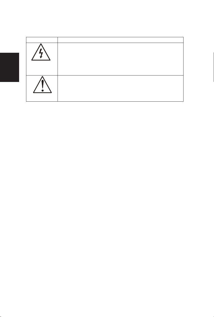
Place unit on even surfaces.
Don't place the TV in confined spaces
or in a box when using it.
Unplug immediately if is malfunction
like no picture, no video/audio,smoke
and bad odor from TV.
Unplug immediately if other foreign
materials are put inside TV box or if
the TV fell down.
Don't throw any object inside the TV
box like metals or other flammable
materials.
Prohibit/Avoid opening TV cabinet
PRECAUTIONS AND REMINDERS
3
English
Page 6
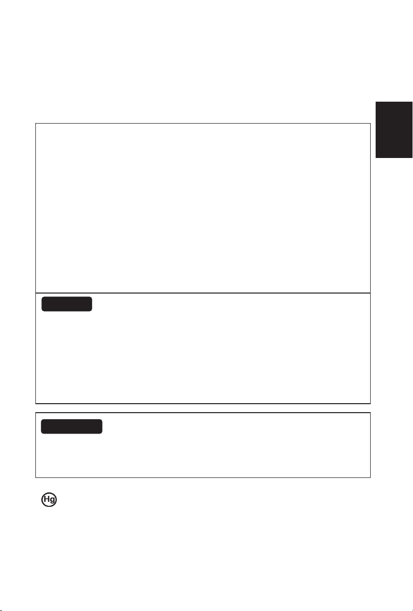
Remember to unplug the AC cord
from the AC outlet before cleaning. Do
not use liquid cleaners or aerosol
cleaners to clean the display.
Avoid direct sunlight, dusty, high
humidity and smoky areas.
Make sure to unplug the unit when not
in use for a long period of time (days).
Call service personnel to clean the
internal part of the TV once a year.
Do not cover or block any vents and
openings. Inadequate ventilation may
shorten the life of the display unit and
cause overheating.
Do not place the display near water,
such as bathtub, washbasin, kitchen
sink laundry tub, swimming pool or in
a damp basement.
Notice for Remote Controller
Avoid Dropping Avoid Liquids Avoid Aerosol Cleaners
1
2
3
4
5
6
7
8
9
0
1
2
3
4
5
6
7
8
9
0
1
2
3
4
5
6
7
8
9
0
4
English
Page 7

Read before operating equipment
1. Read these instructions.
2. Keep these instructions.
3. Heed all warnings.
4. Follow all instructions.
5. Do not use this apparatus near water.
6. Clean only with a dry cloth.
7. Do not block any of the ventilation openings. Install in accordance with the
manufacturers instructions.
8. Do not install near any heat sources such as radiators, heat registers, stoves,
or other apparatus (including amplifiers) that produce heat.
9. Do not defeat the safety purpose of the polarized or grounding type plug. A
polarized plug has two blades with one wider than the other. A grounding
type plug has two blades and third grounding prong. The wide blade or third
prong is provided for your safety. When the provided plug does not fit into
your outlet, consult an electrician for replacement of the obsolete outlet.
10. Protect the power cord from being walked on or pinched particularly at plugs,
convenience receptacles, and the point where they exit from the apparatus.
11. Only use attachments/accessories specified by the manufacturer.
12. Use only with a cart, stand, tripod, bracket, or table specified by the
manufacturer, or sold with the apparatus. When a cart is used, use caution
when moving the cart/apparatus combination to avoid injury from tip-over.
13. The TV should be operated only from the type of power source indicated on
the label. If you are not sure of the type of power supplied to your home,
consult your dealer or local power company.
14. Unplug this apparatus during lightning storms or when unused for long
periods of time.
15. Refer all servicing to qualified service personnel. Servicing is required when
the apparatus has been damaged in any way, such as power-supply cord or
plug is damaged, liquid has been spilled or objects have fallen into apparatus,
the apparatus has been exposed to rain or moisture, does not operate
normally, or has been dropped.
16. This product may contain lead or mercury. Disposal of these materials may
be regulated due to environmental considerations. For disposal or recycling
information, please contact your local authorities or the Electronic Industries
Alliance: www.eiae.org
17. Damage Requiring Service – The appliance should be serviced by qualified
service personnel when:
A. The power supply cord or the plug has been damaged; or
B. Objects have fallen, or liquid has been spilled into the appliance; or
C. The appliance has been exposed to rain; or
D. The appliance does not appear to operate normally or exhibits a marked
change in performance; or
E. The appliance has been dropped, or the enclosure damaged.
IMPORTANT SAFETY INSTRUCTIONS
5
English
Page 8
18. Tilt/Stability – All televisions must comply with recommended international
global safety standards for tilt and stability properties of its cabinets design.
y Do not compromise these design standards by applying excessive pull
force to the front, or top, of the cabinet, which could ultimately overturn
the product.
y Also, do not endanger yourself, or children, by placing electronic
equipment/toys on the top of the cabinet. Such items could
unsuspectingly fall from the top of the set and cause product damage
and/or personal injury.
19. Wall or Ceiling Mounting – The appliance should be mounted to a wall or
ceiling only as recommended by the manufacturer.
20. Power Lines – An outdoor antenna should be located away from power lines.
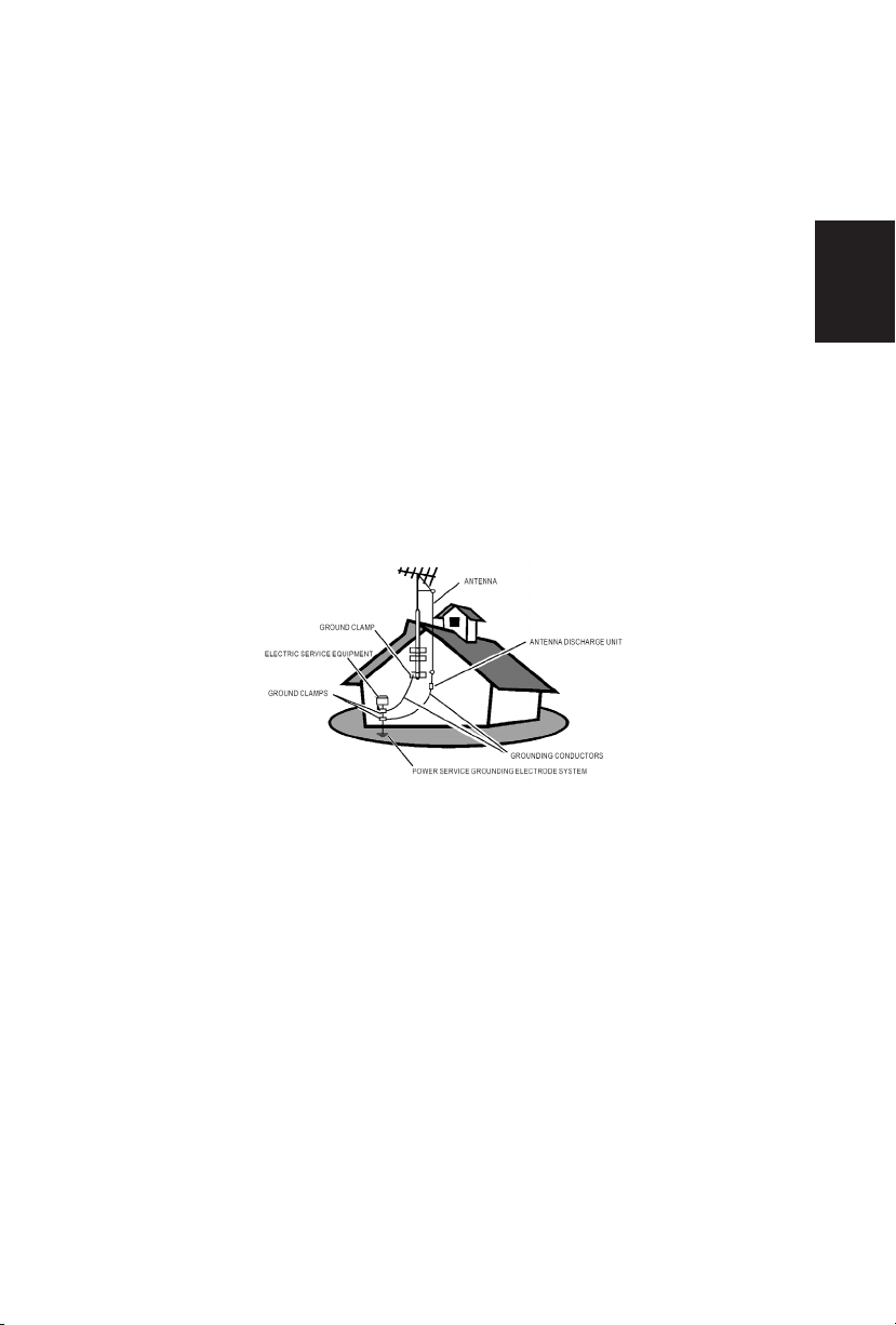
21. Outdoor Antenna Grounding – If an outside antenna is connected to the
receiver, be sure the antenna system is grounded so as to provide some
protection against voltage surges and built up static charges.
Section 810 of the National Electric Code, ANSI/NFPA No. 70-1984, provides
information with respect to proper grounding of the mats and supporting
structure grounding of the lead-in wire to an antenna-discharge unit, size of
grounding connectors, location of antenna-discharge unit, connection to
grounding electrodes and requirements for the grounding electrode. See
Figure below.
EXAMPLE OF ANTENNA GROUNDING AS PER NATIONAL ELECTRICAL
CODE
Note to the CATV system installer: This reminder is provided to call the
CATV system installer’s attention to Article 820-40 of the NEC that provides
guidelines for proper grounding and, in particular, specifies that the cable
ground shall be connected to the grounding system of the building, as close
to the point of cable entry as practical.
Please, make sure to connect the power plug to the wall outlet socket after
connecting the TV to the adapter!
22. Objects and Liquid Entry – Care should be taken so that objects do not fall
and liquids are not spilled into the enclosure through openings.
6
English
Page 9
Package Contents
AOC L32W831 TV unit
Remote Control
Batteries (Except Argentina)
Four M4 screws(to attach the Base to the stand)
Power Cord
Audio cable
signal cable
User Manual
Quick Setup Guide
IMPORTANT: Do not apply pressure to the screen display area which may
compromise the integrity of the display. The manufacturer’s warranty does not
cover user abuse or improper installations.
Attaching the Base
IMPORTANT: The Base of the TV must be assembled prior to usage.
1. Place TV unit face down on a soft and flat surface (blanket, foam, cloth,
etc.) to prevent any damage to the TV.
2. Carefully align and insert the Base to the stand.
3. Gently push the Base towards the TV until the locking mechanism locks
into place.
4. Insert the provided screws to the bottom of the base.
5. Use a screwdriver to tighten the Base to the stand.
7
English
Page 10
200
mm
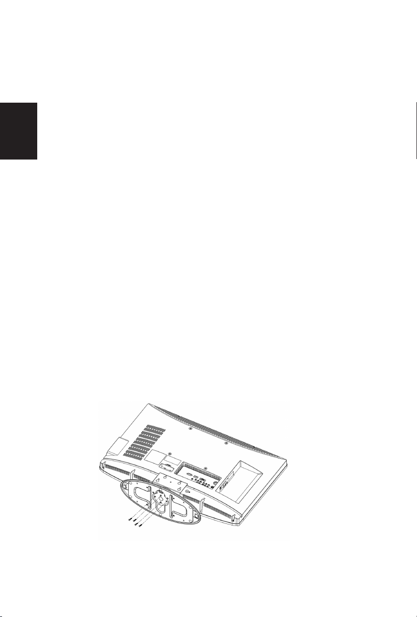
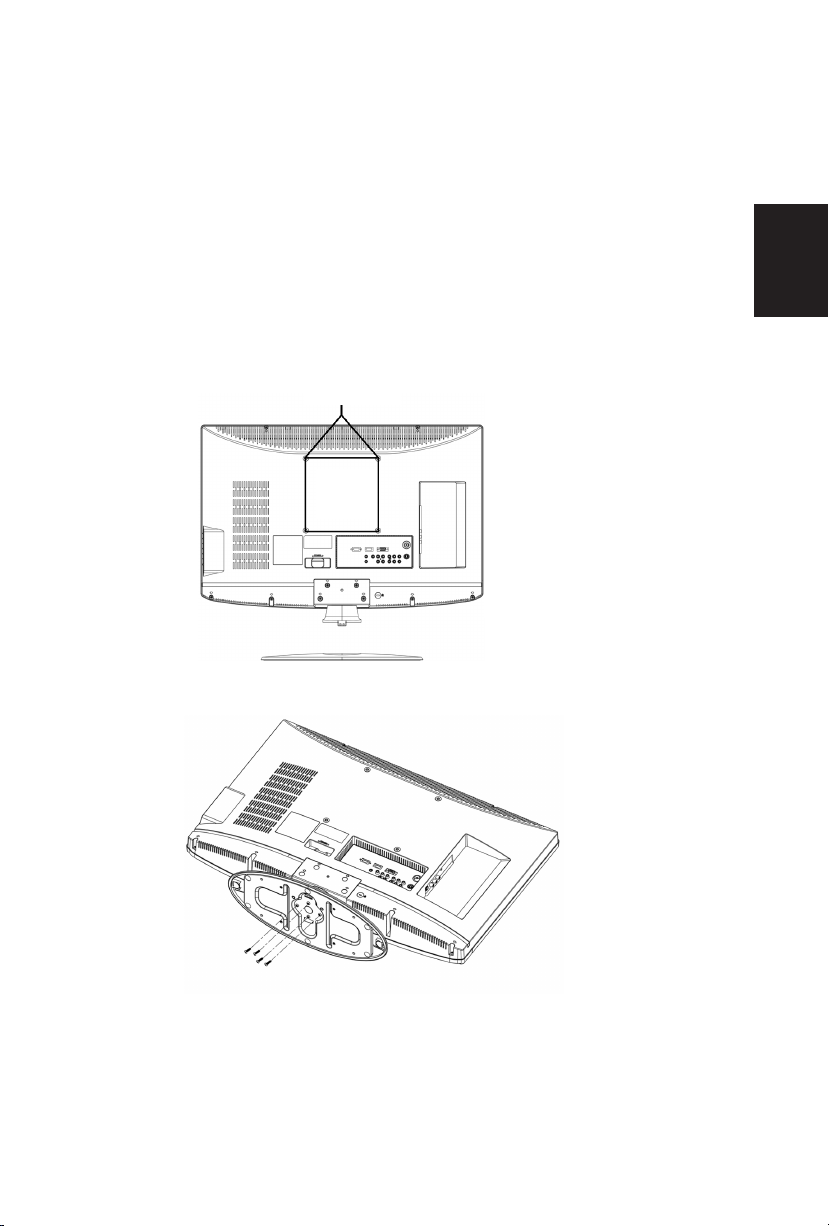
Preparing Your LCD TV for Wall Mounting
We suggest that you keep your TV at least 2.36 inches (60 mm) from the wall to
prevent cable interference.
Before mounting your TV on the wall, you need to remove the base.
To attach a wall mount bracket to your TV:
1 Remove the two T4 and two M4 screws holding your TV to the stand.
2 Remove the four screws from the bottom of the stand.
3 Remove the stand base
4 Secure the wall mount bracket to the back of your TV using four M6 screws,
as indicated in the illustration.
Note: 200mmx200mm wall mount bracket & M6 screws not included.
200mm
Remove M4 screws
Remove stand
Attach
bracket
Remove M4 screws
8
English
Page 11
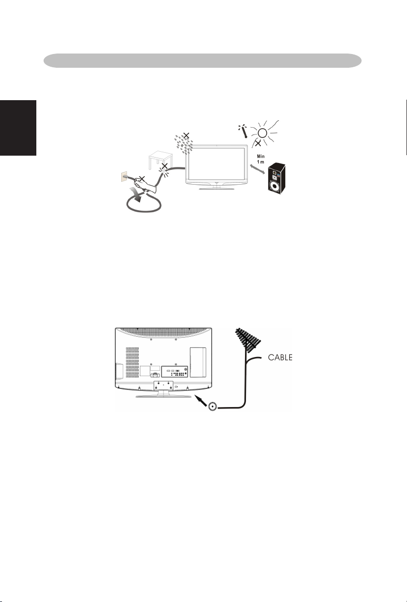
Please, make sure to connect the power plug to the wall outlet socket after
connecting the TV to the power cord!
1
. Install the base stand; place the TV on a solid surface.
Ensure that the TV is placed in a position to allow free flow of air. Do not cover
the ventilation openings on the back cover.
To prevent any unsafe situations, no naked flame sources, such as lighted
candles, should be placed on or in the vicinity.
Avoid heat, direct sunlight and exposure to rain or water. The equipment shall
not be exposed to dripping or splashing.
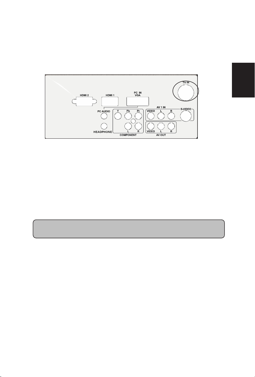
2. Connect the antenna cable or CATV cable to the aerial socket TV IN the back
of the TV set.
PREPARATION
9
English
Page 12
4. Power:
Insert the power cord in the wall socket having an AC power supply. You can
see LED states at the front panel. If the LED color is Blue, means the TV set is
power on. If the LED color is Red which means this TV set is in standby state.
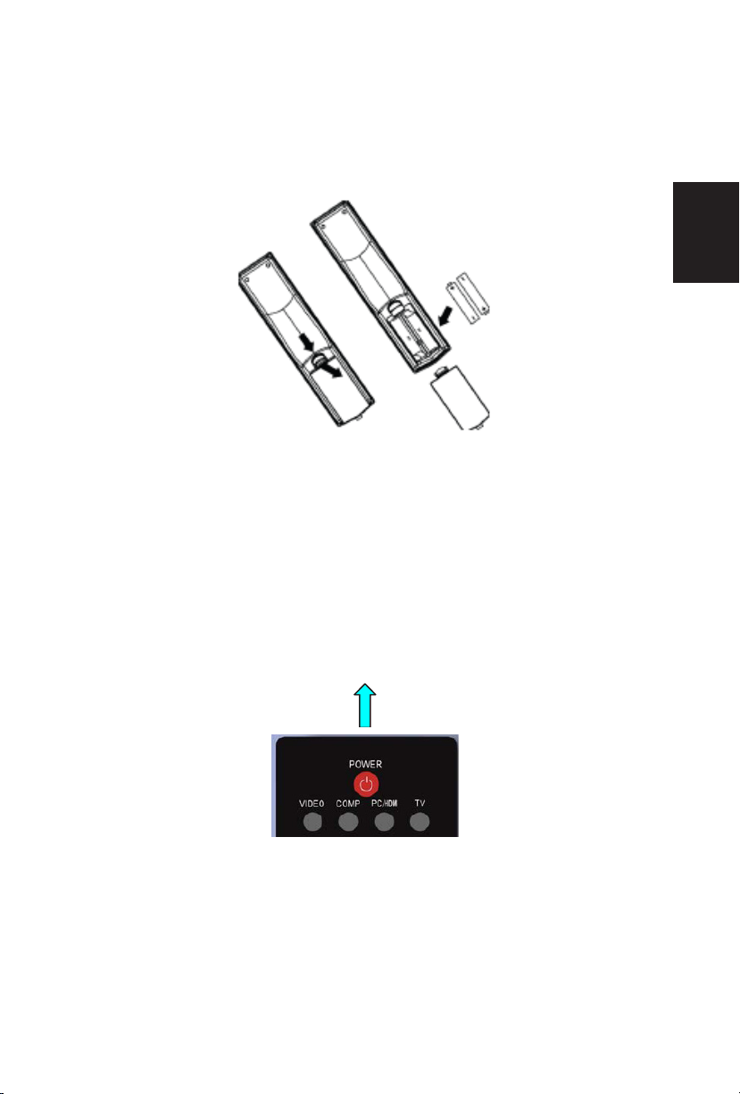
5. Turn the TV on:
Push the POWER key on the Remote control or the Front panel control knobs.
Wait a minute,the TV will power on andcan see the display on the screen
POWER Key
3. Remote control:
Remove the cover of the battery compartment. Insert the 2 batteries supplied
(Type AAA 1.5V).
10
English
Page 13
HDMI S-Video Composite Pr Pb Y PC Line in 15-pin D-Sub
PERIPHERAL CONNECTION GUIDE
11
English
Page 14

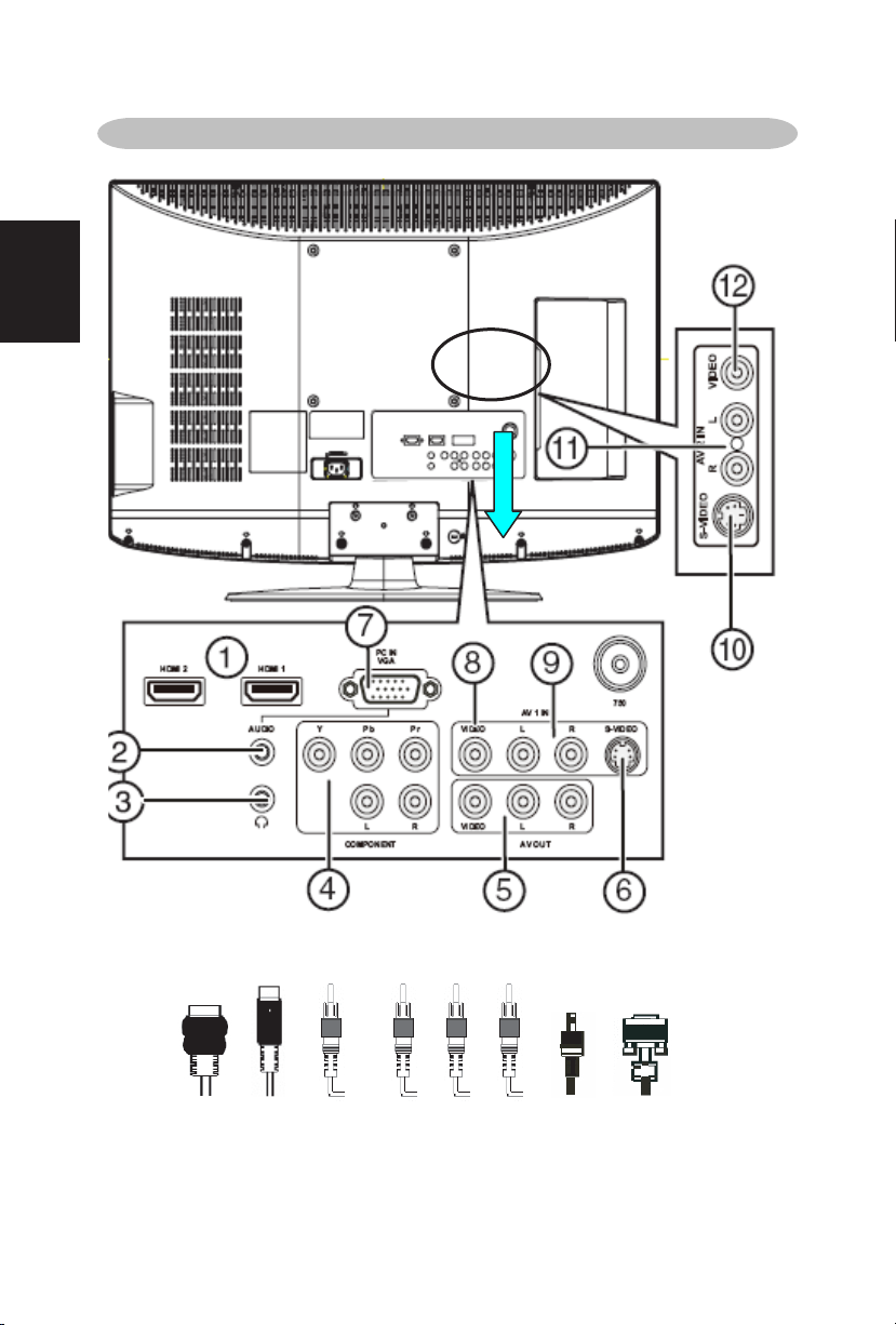
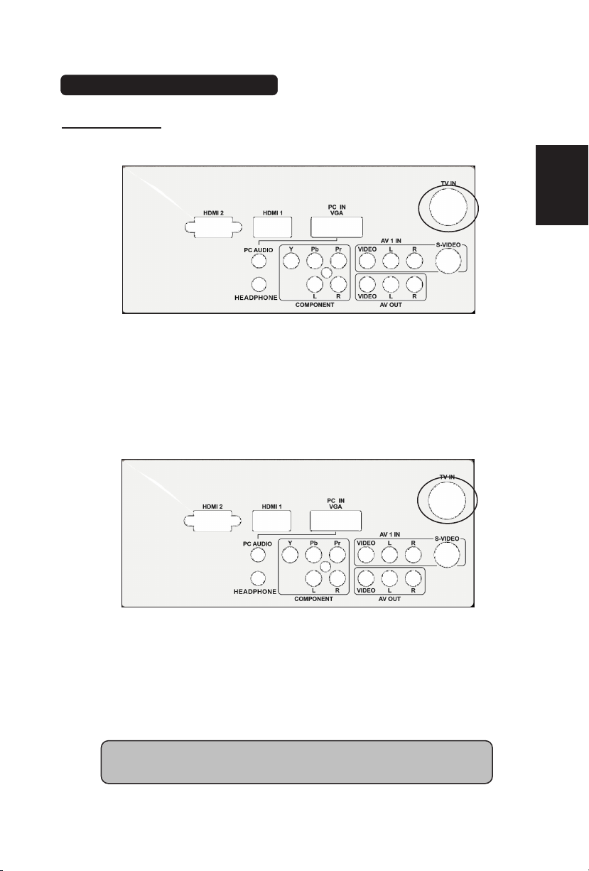
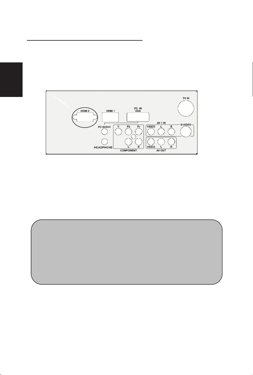
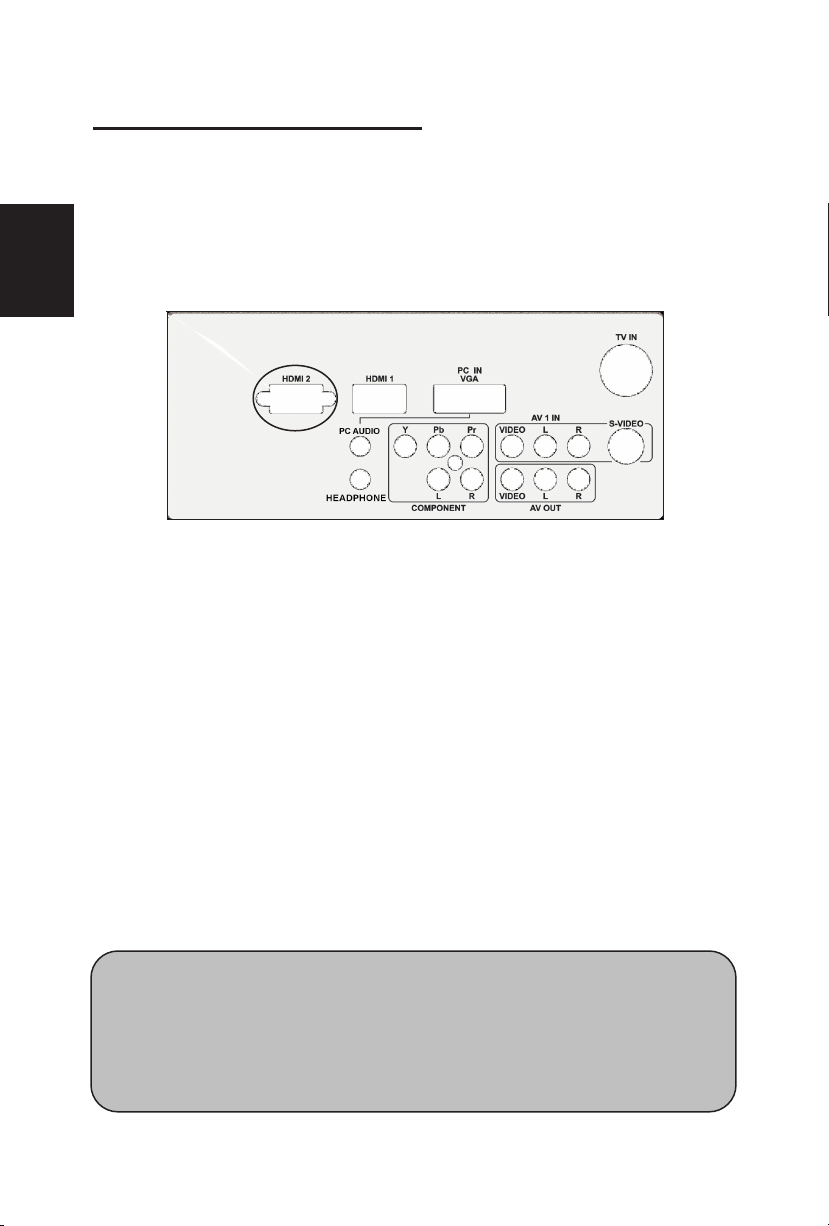
1. HDMI – Connect the primary source for digital video such as a DVD
multimedia player or set top box through this all digital connector.
The white color band on the rear of the TV indicates this connection.
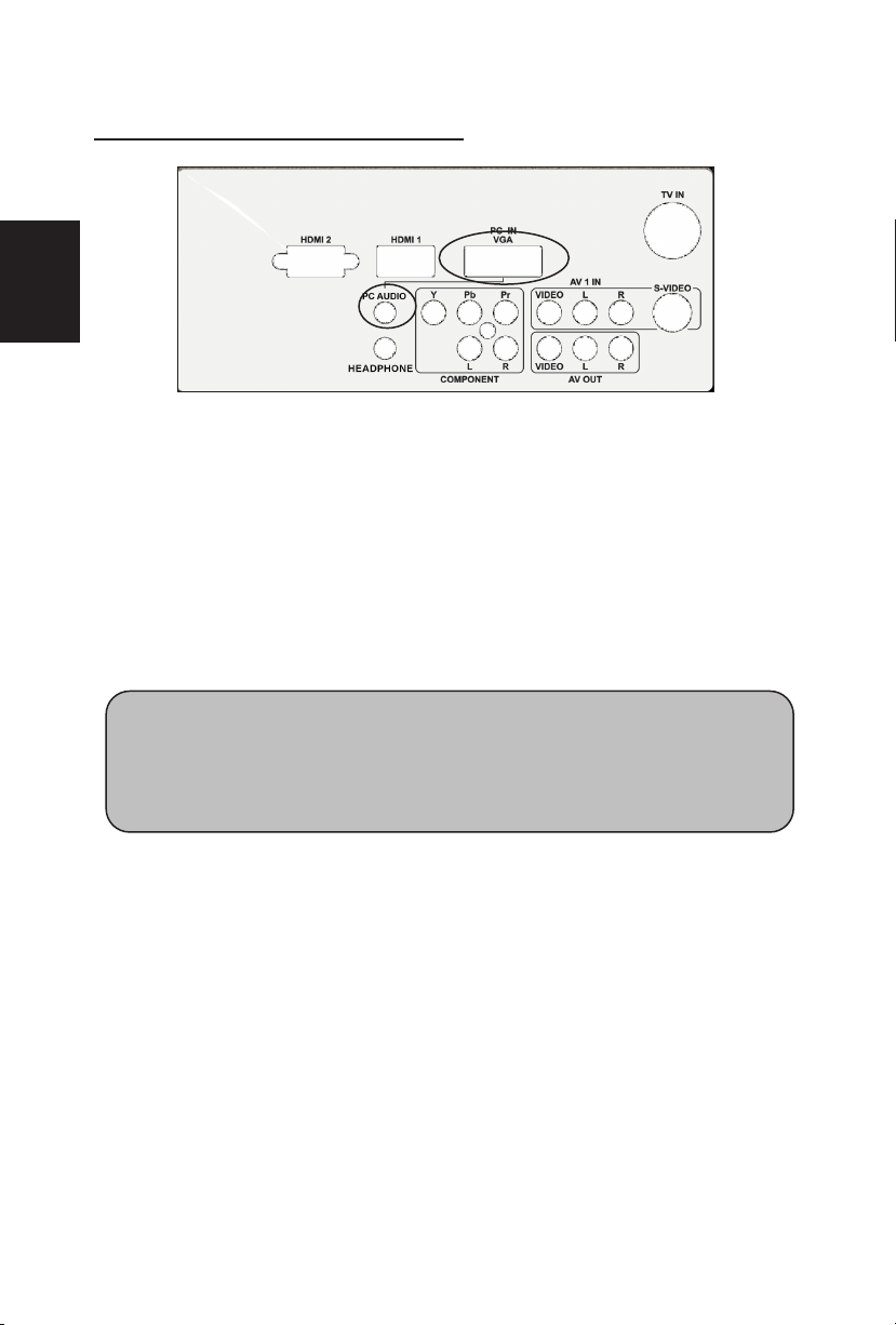
2. VGA AUDIO– Connect the audio for a computer to this jack.
3. HEADPHONE – Connect headphone to this jack.
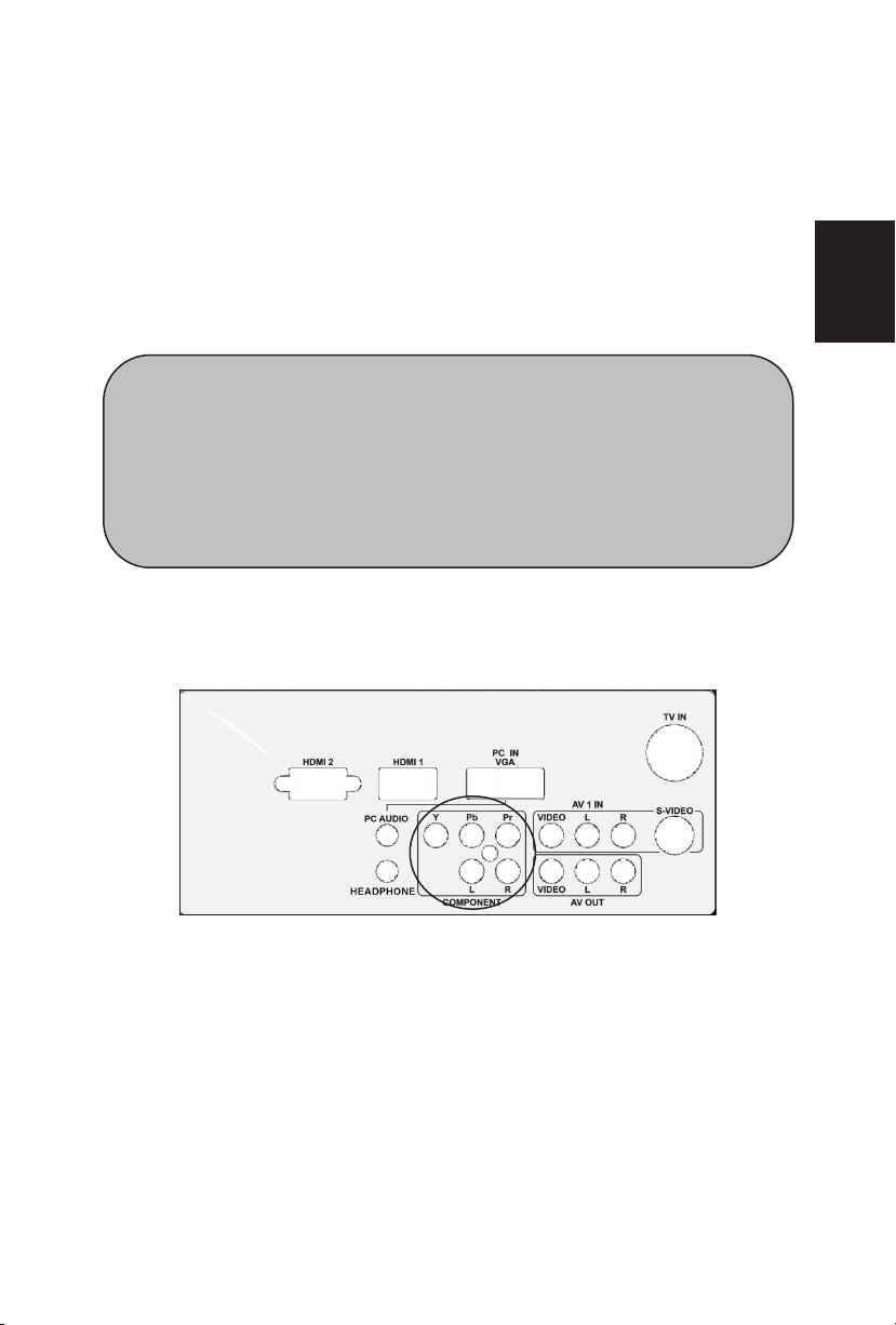
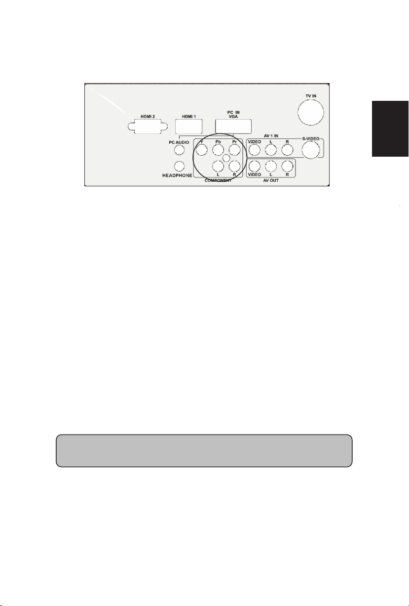
4. COMPONENT (YPb/CbPr/Cr with Audio L/R) – Connect the
primary source for component video devices such as a DVD Player
or set top box here. From left to right, use red for Pr, blue for Pb,
green for Y, red for right audio (R) and white for left audio (L) inputs.
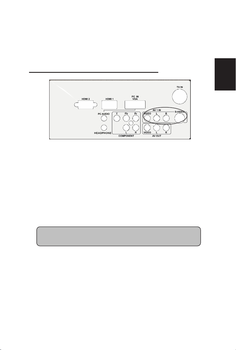
5. AV OUT– Connect a VCR for recording to these jacks
6.
S-VIDEO1 – Connect an S-Video device to this jack.
7. RGB PC – Connect the video and audio cables from a computer
here.
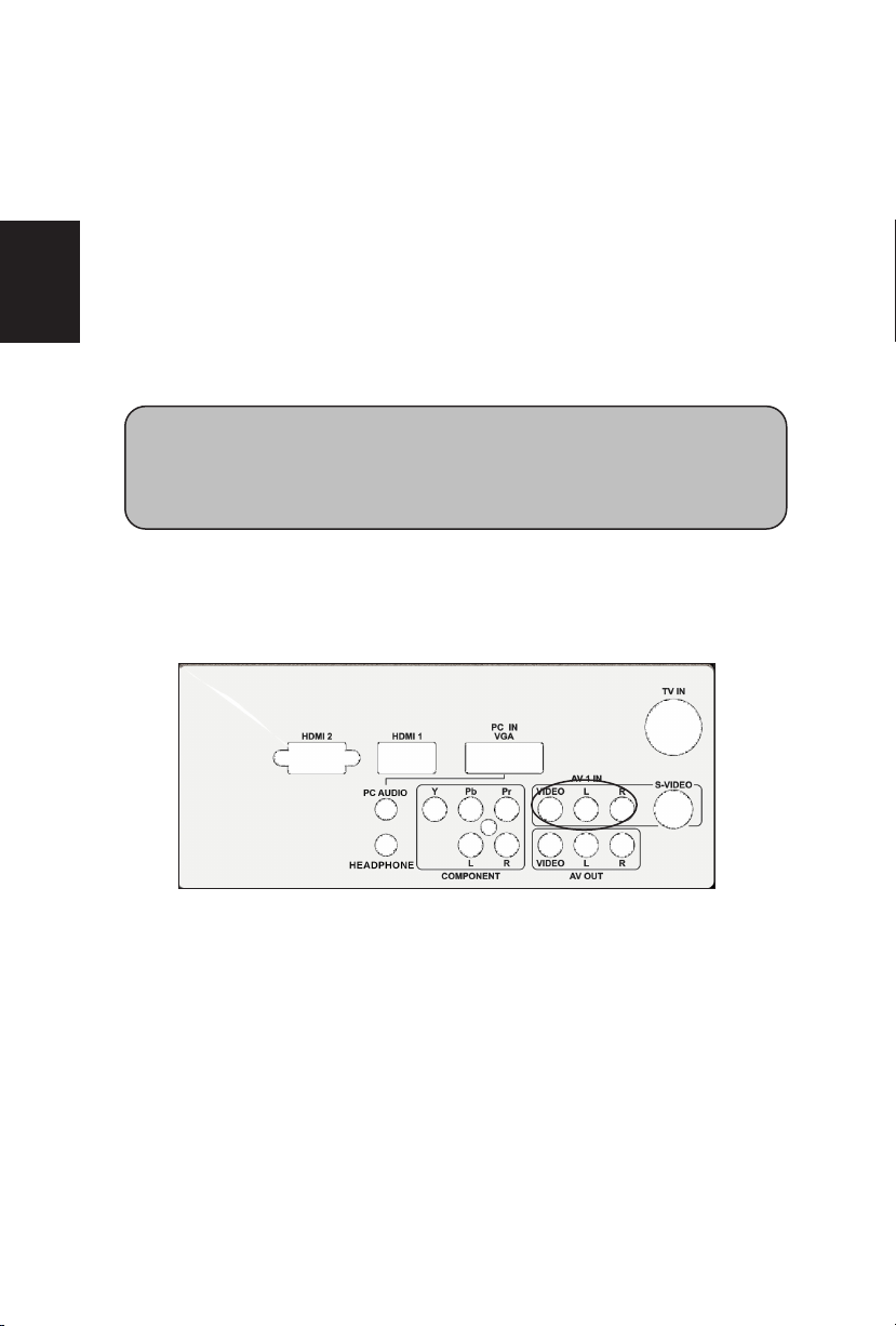
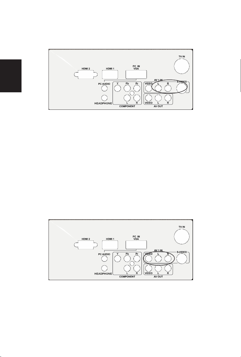
8. AV1 IN – Connect the primary source for composite video devices,
such as a VCR or video game.
9. Use the white and red connectors to connect the external audio from
the same source. The signal being carried by the S-Video cable
and connector, if connected, will take priority over the Video RCA
connector (yellow connector).
10. S-VIDEO2 – Connect an S-Video device to this jack.
11. Use the white and red connectors to connect the external audio from
the same source. The signal being carried by the S-Video cable
and connector, if connected, will take priority over the Video RCA
connector (yellow connector)
12. AV2 IN – Connect the primary source for composite video devices,
such as a VCR or video game.
Once your equipment is connected, use the following procedure to view the input
signal:
Press the source button on the remote controller to select the relevant source to
view. (ex: Press VIDEO button to select “Composite Rear” if you have connected
a video recorder to Composite Rear socket.)
12
English
Page 15
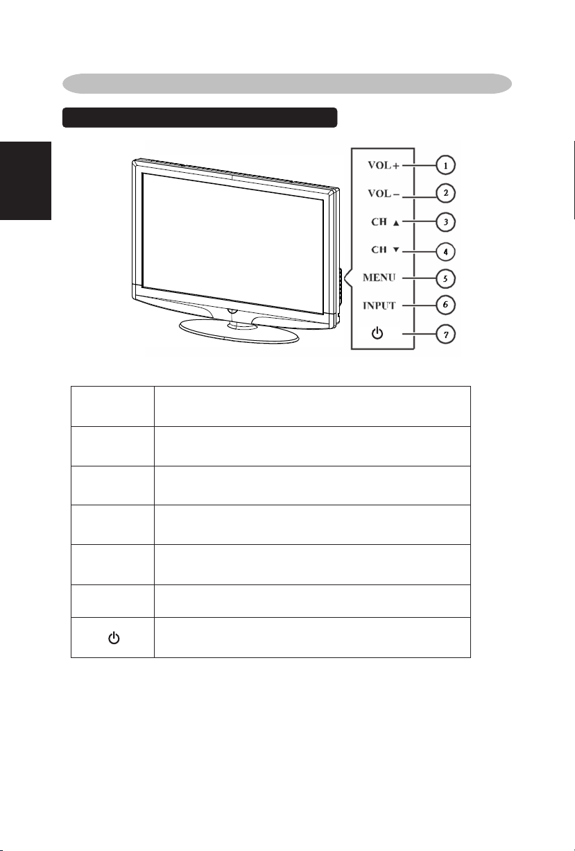
TO USE THE FRONT PANEL CONTROL
1
VOL
VOL +: Press to increase the sound volume level.
2 VOL▼
VOL - : Press to decrease the sound volume level.
3 CH
CH +: Press to select the next higher Program number.
4 CH ▼
CH - : Press to select the next lower Program number.
5 MENU
Menu key: Press
to open or exit the OSD menu.
6 INPUT
Source key: Press to select the input source.
7
Power key: Press to turn on / off (standby) the TV set.
(Please re-turn on TV after the Power-ON status LED had
changed to the Red color and finished flashing.)
OPERATION INSTRUCTIONS
13
English
Page 16
TO USE THE REMOTE CONTROL
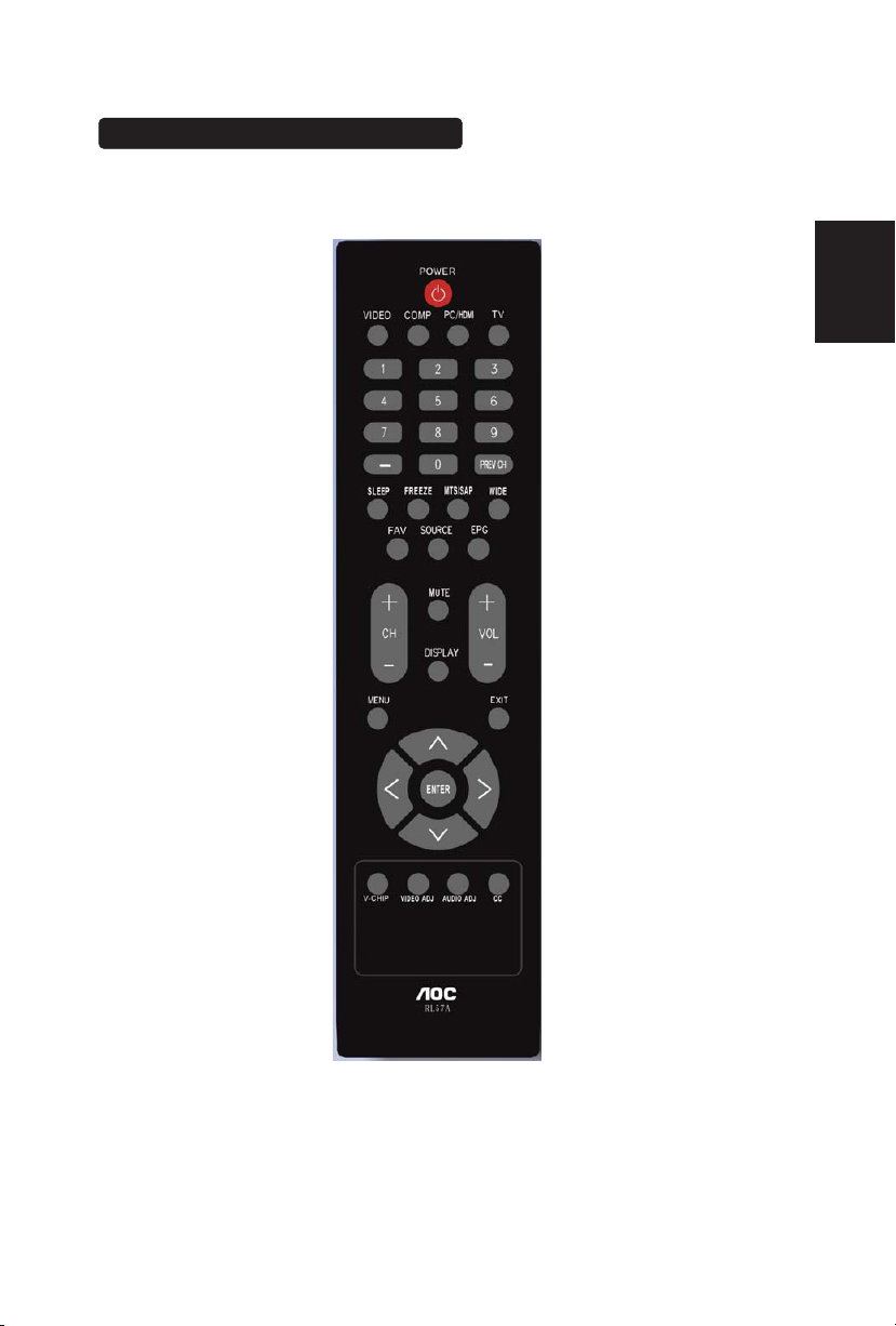
POWER
Press to power ON/OFF (standby)
TV.(Note:1.TV is never completely
power off.
unless physically unplugged.
2.Press to turn on TV after the
power
on status LED had changed to the
red color and stopped flashing. )
VIDEO
Press repeatedly to choose SVideo/Composite source mode
(Video 1 ~ 2).
COMP
Press repeatedly to choose
Component source mode (Video 3 ).
PC/HDMI
Press repeatedly to choose VGA
or HDMI source mode (Video 4 ~
6).
TV
Press to choose TV source mode.
0 ~ 9 /- number
Press to enter TV channel number
to select channel (Press ‘-’ to
indicate choosing the sub-channel).
SLEEP
Press to set a time period (off/5
min /10 min /15 min /30min/45
min /60min/90min/120 min /180
min /240 min)after which the TV
shouldswitch itself to standby
mode.
FREEZE
Press to freeze the displayed
picture
CH-/ CH +
Press + or - to browse through the
TV channels.
MENU
Press to open or exit menu.
“∧”,“∨”,“”,“”,“ENTER
Press to adjust the various function
items on the menu.
PREV CH
Press to display the previous TV .
MTS/SAP
Press to activate the TV sounds,
SAP or Mono tone.
such as:
WIDE
Press to choose the display aspect
as: Normal, Wide, Zoom or Cinema
mode.
SOURCE
Press repeatedly to choose the
various input sources.
EPG
This function is not support.
MUTE
Press to set TVsound mute ON/OFF
DISPLAY
Press to show the information about
the input source、TV channel、
display resolution and current time.
VOL- / VOL+
Press + or - to adjust the volume.
Exit
Press to exit menu or OSD.
V-CHIP
This mode don’t have this function
VIDEO ADJ
Press to choose the Brightness or
Contrast adjustment.
AUDIO ADJ
Press to switch the multi-channel TV
sounds.
CC
Press repeatedly to change the
closed caption type as CC ON/CC
OFF/CC ON when mute.
UNIVERSAL REMOTE CONTROL
PROGRAMMING
ThisTViscompatiblewiththepopular
universalremotecontrol.
Brand: Philips
Programcode: 002
English
14
Page 17
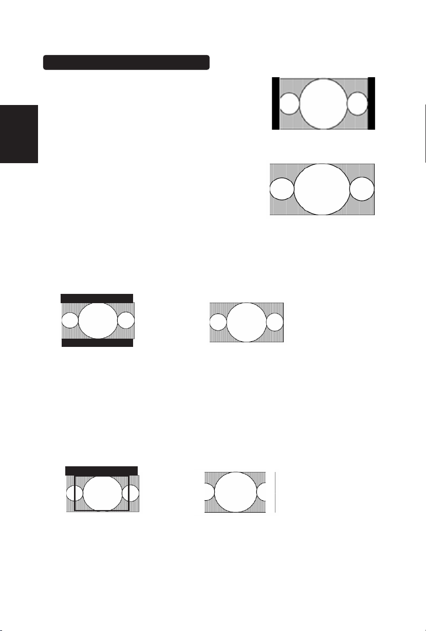
Viewing Modes illustrations
Normal Mode on 16:9 Display screen
The original content would be at the center of the
screen.
Wide Mode on 16:9 Display screen
The original content in this mode has to fill the
entire width of the display horizontally.
ZOOM Mode on 16:9 Display screen
For those wide format images which are originally programmed into 4:3 frames
with top and bottom black bars, this mode has to stretch the image in both wide
and high directions to the full display with active data.
CINEMA Mode on 16:9 or 16:10 Display screen
This mode is applied to view 2.35:1 format content on 16:9 displays. To crop both
right and left sides a little for keeping the undistorted ratio of the image is provide
for users.
16:9 image in 4:3 frame
Same image in ZOOM mode
15
English
Page 18
Connecting Equipment
Coaxial (RF)
Using Your Antenna or Cable for TV
1. Turn off the power to the TV.
2. Connect the coaxial (RF) connector from your antenna or cable (outof-the-wall, not from the Cable Box) to the TV IN connector
3. Turn on the power to the TV.
4. Select TV using the INPUT button on the remote, side of the TV or
directly by pressing the TV button on the Remote Control.
Using the Antenna or Cable for your VCR
1. Turn off the power to the TV and VCR.
2. Connect the “Output to TV”, “RF Out” or “Antenna Out” connector
on the rear of your VCR to the TV IN connector at the rear of the TV.
3. Turn on the power to the TV and VCR.
4. Select TV using the INPUT button on the remote, side of the TV or
directly by pressing the TV button on the Remote Control.
Note: If you have an off-air antenna or cable TV, connect it to the
“Antenna In” connector on the rear of
y
our VCR.
16
English
Page 19
Connecting Your TV Set-Top Box
Using HDMI
TV Set-Top Boxes that have a HDMI digital interface should be connected to the
HDMI input of the LCD TV for optimal results.
Connecting your TV Set-Top Box (Best)
Turn off the power to the TV and TV Set-Top Box.
1. Connect a HDMI cable to the HDMI output of your TV Set-Top Box
and the other end to the HDMI Input at the rear of the TV.
2. Turn on the power to the TV and TV Set-Top Box.
3. Select HDMI using the INPUT button on the remote, side of the TV,
or directly by pressing the HDMI button on the Remote Control.
Note:
a)
The HDMI input on the TV supports High-bandwidth Digital
Content Protection (HDCP). HDCP encrypts the transmission
between the video source and the digital display for added
security and protection.
b)
Refer to your TV Set-Top Box user manual for more information
about the video output requirements of the product or consult
your cable or satellite operator
17
English
Page 20
For TV Set-Top Boxes with DVI
1. Turn off the power to the TV and TV Set-Top Box.
2. Using a HDMI-DVI cable, connect the DVI end to your TV Set-Top
Box and the HDMI end to the HDMI Input at the rear of the TV.
3. Turn on the power to the TV and TV Set-Top Box.
4. Select HDMI using the INPUT button on the remote, side of the TV,
or directly by pressing the HDMI button on the Remote Control.
Using Component Video
Connecting your TV Set-Top Box (Better):
1. Turn off the power to the TV and TV Set-Top Box.
2. Connect the Pr (red color) connector on your TV Set-Top Box to the
corresponding Pr (red color) connector in the Component group.
3. Connect the Pb (blue color) connector on your TV Set-Top Box to
the corresponding Pb (blue color) connector in the Component
group.
Note:
a) The HDMI input on the TV supports High-bandwidth Digital Content
Protection (HDCP). HDCP encrypts the transmission between the
video source and the digital display for added security and protection.
b) Refer to your TV Set-Top Box user manual for more information about
the video output requirements of the product or consult your cable or
satellite operator.
c) The DVI to HDMI connection provides video only. Connection to an
alternate audio player is required for audio.
18
English
Page 21
4. Connect the Y (green color) connector on your TV Set-Top Box to
the corresponding Y (green color) connector in the Component
group.
5. Using an audio cable (red and white connectors), connect the cable
to the audio output connectors associated with the Component
output on your TV Set-Top Box and connect the other end to the
audio connectors associated with the Component.
6. Turn on the power to the TV and TV Set-Top Box.
7. Select Component (Video 3) using the INPUT button on the remote,
side of the TV or directly by pressing the Component button on the
Remote Control.
Connecting Your Basic Set-Top Box
Using Composite Video
1. Turn off the power to the TV and Set-Top Box.
2. Using an AV Cable, connect the Video (yellow color) connector on
your Set-Top Box to the corresponding Video (yellow color)
connector in the AV group at the rear of the TV.
3. Using the red and white connectors, connect the cable to the audio
output connectors associated with the Video output on your Set-Top
Box and connect the other end to the audio connectors associated
with the AV input at the rear of the TV.
4. Turn on the power to the TV and Set-Top Box.
Note:
Refer to your TV Set-Top Box user manual for more information
about the video output requirements of the product or consult your
cable or satellite o
p
erato
r
.
19
English
Page 22
5. Select Composite (Video 1) using the INPUT button on the remote,
side of the TV or directly by pressing the AV button on the Remote
Control.
Using Coax (RF)
1. Turn off the power to the TV and Set-Top Box.
2. Using a Coax (RF) cable, connect one end to the TV OUT (RF) on
your Set Top Box and the other end to the DTV/TV input at the rear
of the TV.
3. Turn on the power to the TV and Set-Top Box.
4. Select TV using the INPUT button on the remote, side of the TV or
directly by pressing the TV button (below the WIDE button) on the
Remote Control.
Note: Refer to your Set Top Box user manual for more information about
selectin
g
the video or RF output of the product.
20
English
Page 23
Connecting Your DVD Player
Using HDMI
DVD players that have a digital interface such as HDMI (High Definition
Multimedia Interface) should be connected to the HDMI input of the LCD TV for
optimal results.
Connecting your DVD Player (Best)
1. Turn off the power to the TV and DVD player.
2. Connect a HDMI cable to the HDMI output of your DVD player and
the other end to the HDMI Input at the rear of the TV.
3. Turn on the power to the TV and DVD player.
4. Select HDMI using the INPUT button on the remote, side of the TV
or directly by pressing the HDMI button on the Remote Control.
For DVD Players with DVI:
1. Turn off the TV and DVD player.
2. Using a HDMI-DVI cable, connect the DVI end to your DVD player
and the HDMI end to the HDMI Input at the rear of the TV.
3. Turn on the power to the TV and your DVD player.
4. Select HDMI using the INPUT button on the remote or side of the
TV, or directly by pressing the HDMI button on the Remote.
Note:
1. Refer to your DVD player user manual for more information about the
video output requirements of the product.
2. The DVI to HDMI connection provides video only. Connection to an
alternate audio player is required for audio output.
21
English
Page 24
Using Component Video
Connecting your DVD Player (Better)
1. Turn off the power to the TV and DVD player.
2. Connect the Pr (red color) connector on your DVD player to the
corresponding Pr (red color) connector in the Component at the rear
of the TV.
3. Connect the Pb (blue color) connector on your DVD player to the
corresponding Pb (blue color) connector in the Component group at
the rear of the TV.
4. Connect the Y (green color) connector on your DVD player to the
corresponding Y (green color) connector in the Component group at
the rear of the TV.
5. Using an audio cable (red and white connectors), connect the cable
to the audio output connectors associated with the Component
output on your DVD player and connect the other end to the audio
connectors associated with the Component input at the rear of the
TV.
6. Turn on the power to the TV and DVD player.
7. Select Component using the INPUT button on the remote, side of
the TV or directly by pressing the Component button on the Remote
Control.
Note: Refer to your DVD player user manual for more information
about the video output requirements of the product.
22
English
Page 25
Using S-Video (AV)
Connecting your DVD Player (Good):
1. Turn off the power to the TV and DVD player.
2. Connect the S-Video jack on the rear of your DVD player to the SVideo jack in the AV group on the rear of the TV.
3. Connect an audio cable (white and red connectors) to the audio
output connectors associated with the S-Video output on your DVD
player and connect the other end to the audio connectors
associated with the AV input on the rear of the TV.
4. Turn on the power to the TV and DVD player.
5. Select S-Video (Video 2) using the INPUT button on the remote,
side of the TV, or directly by pressing the AV button on the Remote
Control.
Using Composite (AV) Video
Connecting your DVD Player (Good)
1. Turn off the power to the TV and DVD player.
2. Connect the Video (yellow color) connector on your DVD player to
the Video (yellow color) connector in the AV group.
3. Connect the R (red color) and L (white color) audio connectors on
your DVD player to the corresponding R (red color) and L (white
color) audio input connectors in the AV group.
23
English
Page 26
4. Turn on the power to the TV and DVD Player.
5. Select Composite (Video 1) using the INPUT button on the remote,
side of the TV or directly by pressing the AV button on the Remote
Control.
Connecting Your VCR or Video Camera
1. Turn off the TV and VCR or Video Camera.
2. Connect the S-Video jack on the rear of your VCR or Video Camera
to the S-Video jack in the AV group on the rear of the TV.
3. Connect an audio cable (white and red connectors) cable to the
audio output connectors associated with the S-Video output on your
VCR or Video Camera and connect the other end to the audio
connectors associated with the AV input on the rear of the TV.
4. Turn on the power to the TV and VCR or Video Camera.
5. Select S-Video (Video 2) using the INPUT button on the remote,
side of the TV or directly by pressing the AV button on the Remote
Control.
Note: Refer to your VCR or Video Camera user manual for more
information about the video output requirements of the product.
24
English
Page 27
Connecting to a PC Computer
1. Turn off the power to the TV and PC Computer.
2. Connect a 15-pin D-Sub RGB (VGA) cable to the RGB output of
your pc computer and the other end to the RGB PC input at the rear
of the TV.
3. Connect the Audio Out on your pc computer to the RGB PC Audio
input at the rear of the TV.
4. Turn on the TV and PC Computer.
5. Select RGB using the INPUT button on the remote, side of the TV
or directly by pressing the RGB button on the Remote.
Note: For the best picture quality when connecting a PC computer through
RGB PC, set your PC computer timing mode to native resolution of panel.
Please refer to the PC or graphic card’s user guide for additional
information on how to set the timing mode and the video output
re
q
uirements of the product.
25
English
Page 28
TO USE THE MENUS
1. Press the MENU button to display the main menu
2. Use the cursor up/down to select a menu item.
3. Use the cursor left/right to enter a submenu.
4. Press the ENTER button to enable/disable the function.
5. Press the MENU or EXIT button to exit the menu.
Press the MENU button to enter the main OSD (On Screen Display). Adjust the
items including Setup menu, Video menu, Audio menu and Feature menu.
However, some function items in the menus may only be enabled in the particular
source modes.
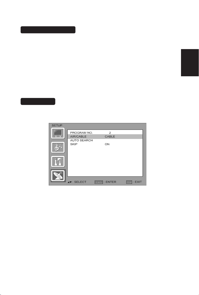
SETUP MENU
The Setup menu in TV mode shows as below. In others source modes, the Setup
menu only shows Menu Language and Aspect Ratio items.
1. PROGRAM NO: Show the TV channel label menu for user modifying channel
labels specifically.
2. AIR/ CABLE: Select TV source signal from the Air (antenna) or Cable (CATV).
3. AUTO SEARCH: Automatically scan all NTSC TV channels and then
store in the channel table. In channel scan process, the OSD can
display the number of channels which had been found.
4. SKIP :you can select the ship ON/OFF ,so that the program no channel can be
delete or added.
26
English
Page 29
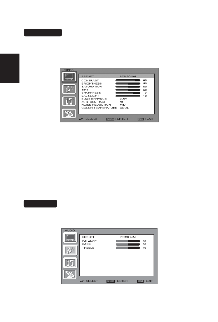
VIDEO MENU
27
The Video menu in most source modes shows as below. It provides several video
adjustment items for user fine tuning the video display. Only in VGA source
English
modes, the Video menu simply provides Contrast, Brightness, Back light and
Settings (Preset) items.
If you selected PERSONAL, press or to highlight an option, then press
∧or∨ to adjust the option. You can adjust:
1. CONTRAST: Video contrast adjustment, the tuning range is 0 ~ 100.
2. BRIGHTNESS: Video brightness adjustment, the tuning range is 0 ~ 100.
3.SATURATION: COLOR saturation adjust, the tuning range is 0 ~ 100
4. TINT: Video tint adjustment, the tuning range is R50 ~ G50.
5. SHARPNESS: Video sharpness adjustment, the tuning range is 0~10
6. BACKLIGHT: Backlight strength adjustment, the tuning range is 0 ~ 10.
7. EDGE ENHANCE:
AUTO CONTRAST: Select ON to automatically adjust contrast.
8.
9.NOISE REDUCTION: Press < or > to select HIGH,OFF, LOW,or MID.
10.COLOR TEMPERATURE:
WARM.
AUDIO MENU
The Audio menu in TV mode shows as below. It provides audio adjustment for
user to modify the audio setting. Audio language setting is only available with
ATSC TV source, the option is disable under other source modes.
Press < or > to select HIGH, OFF, or LOW.
Press < or > to select COOL, STANDARD, or
Page 30
Press
∧or ∨to highlight AUDIO, then press > The AUDIO menu opens.
Press
∧or ∨ to highlight PRESET, then press < or > to select an audio mode.
You can select:
• VOICE
• MUSIC
• THEATER
• PERSONAL
If you selected PERSONAL, press
∧ or∨ to highlight an option, then press ∧
or
∨to adjust the option. You can adjust:
• BALANCE—Adjusts the balance between the right and left audio channels.
• BASS—Adjusts the low sounds.
•TREBLE—Adjusts the high sounds.
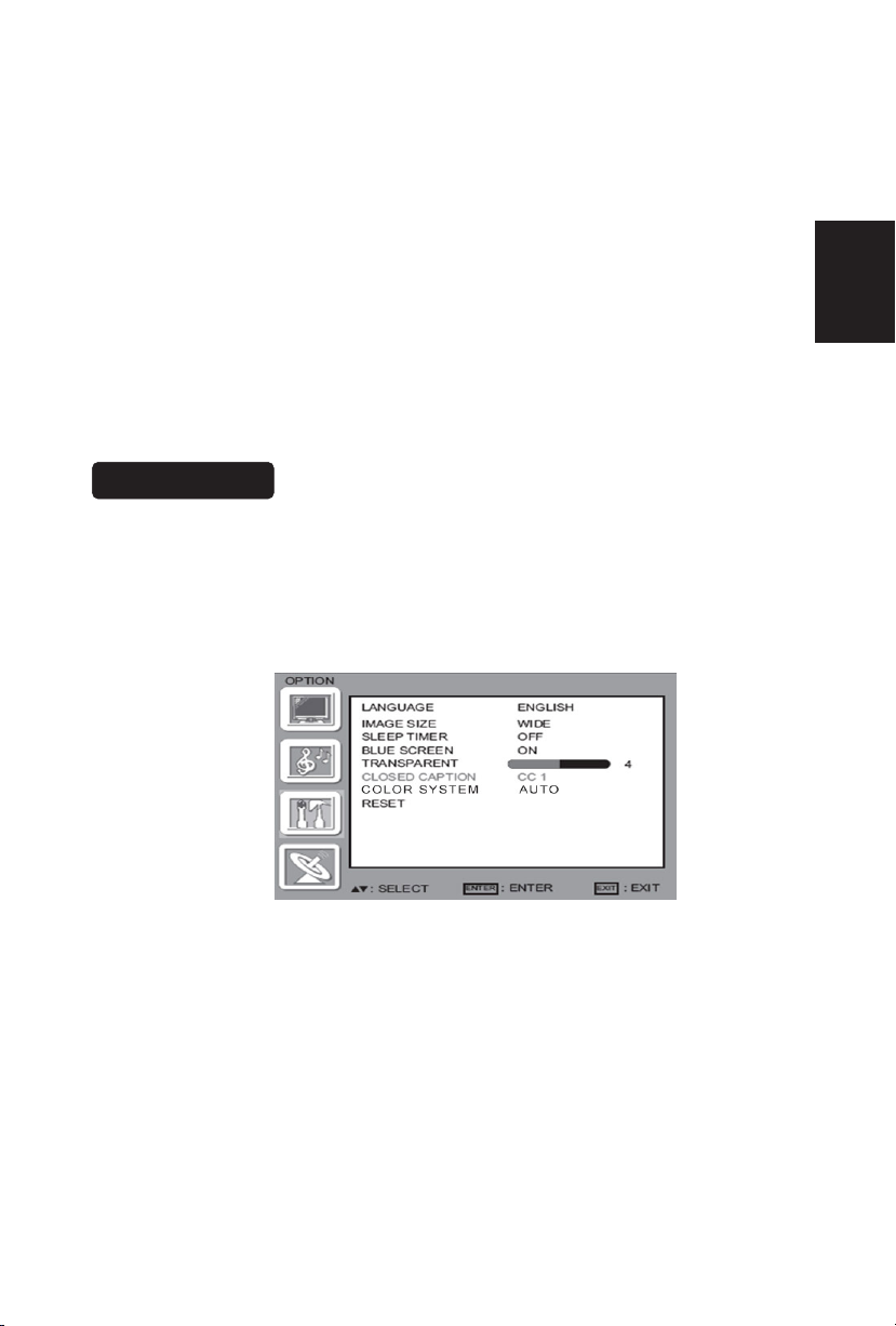
FEATURE MENU
The Feature menu in av/S-video mode shows as below. It provides certain
optional control functions such as inmage size, sleep timer, blue screen on/off,
transparent, closed caption, color systerm. This menu gives users the most
flexibilities to satisfy their generally demands. According to the various
requirements in different source modes, certain features should be hidden
(disable) on the menu. The details footnotes will be described clearly below.
1. LANGUAGE: you can selete the ENGLISH SPANISH Portuguese French
2. IMAGE SIZE : you can selete WIDE, ZOOM, CINEMA, NORMAL
3. SLEEP TIMER: Enable or disable the TV standby timer. User can set the TV
standby timer as off / 5 min / 10 min / 15 min/ 30 min / 45 min / 60 min/ 90
min / 120 min / 180min/ 240min. Timer starts to count down after cursor
28
English
Page 31

leaving the sub-menu. (At the moment, the item shows ** min Leftand
the cursor highlights on the Feature icon.)
4. BLUE SCREEN: you can selete blue screen ON/OFF
5. TRANSPARENT: you can selete from 0 to 7
VGA SETTING MENU
VGA Set: This option only shows and is available in VGA mode, which provides
several items for the VGA display fine tuning, such as : H-PositionV-
PositionClockand Phase. All these items giving the tuning range
from 0 to 100. Setting item provides the default VGA setting values
restoring.
6. CLOSED CAPTION:Press or to highlight CLOSED CAPTION, then press
or to select the closed captioning mode. You can select CC1,CC2, CC3,
CC4, TT1, TT2, TT3 or TT4.
7. COLOR SYSTEM: this function you select color system,default is auto,you
can choose NTSC, PAL M, PAL N.
8. RESET: you can use it reset all setting to default.
29
English
Page 32

TIPS
Care of the screen
Do not rub or strike the screen with anything hard as this may scratch, mar, or
damage the screen permanently.
Unplug the power cord before cleaning the screen. Dust the TV by wiping the
screen and the cabinet with a soft, clean cloth. If the screen requires additional
cleaning, use a clean, damp cloth. Do not use liquid cleaners or aerosol cleaners.
Mobile telephone warning
To avoid disturbances in picture and sound, malfunctioning of your TV or even
damage to the TV, keep away your mobile telephone from the TV.
End of life directives
We are paying a lot of attention to produce environmentally friendly in green focal
areas. Your new receiver contains materials, which can be recycled and reused.
At the end of its life specialized companies can dismantle the discarded receiver
to concentrate the reusable materials and to minimize the amount of materials to
be disposed of.
Please ensure you dispose of your old receiver according to local regulations.
Regulatory Notices – Federal Communications Commission Notice
This equipment has been tested and found to comply with the limits for a Class B
digital device, pursuant to part 15 of the FCC Rules. These limits are designed to
provide reasonable protection against harmful interference in a residential
installation. This equipment generates, uses, and can radiate radio frequency
energy and, if not installed and used in accordance with the instructions, may
cause harmful interference to radio communications. However, there is no
guarantee that interference will not occur in a particular installation. If this
equipment does cause harmful interference to radio or television reception, which
can be determined by turning the equipment off and on, the user is encouraged to
try to correct the interference by one or more of the following measures:
˙Reorient or relocate the receiving antenna.
˙Increase the separation between the equipment and the TV.
˙Connect the equipment into wall power outlet on a circuit different from that to
which the receiver is connected.
˙Consult the dealer or an experienced radio or television technician for help.
Modifications –
The FCC requires the user to be notified that any changes or modifications made
to this device that are not expressly approved by Norcent Technology Inc. may
void the user’s authority to operate the equipment.
30
Cables –
Connections to this device must be made with shielded cables with metallic
RF/EMI connector hoods to maintain compliance with FCC Rules and Regulations.
English
Page 33

NOTE:
*This model complies with the specifications listed below.
*Designs and specifications are subject to change without notice.
*This model may not be compatible with features and/or specifications that may
be added in the future.
*32” LCD TV (31.5” viewable) Viewable image size: diagonal 800mm
Television System:
NTSC standard
PAL M/N
HDMI Terminals:
HDMI INPUT: Rear HDMI x2
HDCP compliant
E-EDID compliant
Supported scan rates: 1080i, 720p, 480p, 480i
Channel Coverage:
VHF: 2 through 13
UHF: 14 through 69
Cable TV: Mild band (A - 8 through A - 1, A through
I )
Super band (J through W)
Hyper band (AA through ZZ, AAA, BBB)
Ultra band (65 through 94, 100 through 125)
VGA Terminals:
VGA INPUT:
Rear VGA (D-SUB 15 Pin) Input x1
E-EDID compliant
Supported scan rates: 640X480 /60Hz/72Hz/75Hz
720X400 /70Hz
800x600 /56Hz /60Hz /72Hz
/75Hz
1024X768 /60Hz/70Hz/75Hz
1360X768 /60Hz
Recommended: 1360X768 /60Hz
Audio INPUT: Headphone Mini-jack for stereo (3.5Φ)
Power Source:
AC power supply: 100V~240 V, 50/60 Hz
Power Consumption
≤ 180 W
1 W in standby mode (power cord plugged in
and power OFF)
Dimensions:
Include Stand:
782.5mm(W) x 558.6mm(H) x 209.4mm(L)
Audio Power
5 W + 5 W, Internal Speaker
Weight:11.7kg(With Stand)
Video/Audio Terminals:
Rear AV x1 ,Side AV x1
S-Video/Video/Audio Input
Rear AV out x1
Video/Audio output
Wall Mounting:
200x200mm
(Wall mount kit is not included)
S-VIDEO INPUT:
Y : 1 V(p-p), 75 ohm, negative sync.
C : 0.286 V(p-p) (burst signal), 75
ohm
VIDEO/AUDIO INPUT:
VIDEO: 1 V(p-p), 75 ohm, negative sync.
AUDIO: 0.5V(rms)
Component INPUT:
Rear Component x1:
Y : 1V(p-p), 75 ohm, including sync.
Pr/Cr: ±0.35V(p-p), 75 ohm
Pb/Cb: ±0.35V(p-p), 75 ohm
AUDIO: 0.5V(rms)
Supported resolutions:1080i, 720p,
Supplied Accessories:
Remote Control
Two (AAA) Batteries (Except Argentina)
Base
Four M4 screws (to attach the Base to the stand)
Power Cord
Signal cable
Aduio cable
User Manual
Quick Setup Guide
PRODUCT SPECIFICATION
480p,480i
English
31
Page 34

Please make these simple checks before calling service. These tips may save
you time and money since charges for receiver installation and adjustments of
customer controls are not covered under your warranty.
Symptoms Items to Check and Actions to follow
“Ghost ” or double image
*This may be caused by obstruction to the
antenna due to high rise buildings or
hills. Using a highly directional antenna
may inprove the picture.
No power *Check that the TV’s AC power cord is plugged
into the mains socket.
*Unplug the TV, wait for 60 seconds. Then re-
insert plug into the mains socket and turn on
the TV again.
No picture *Check antenna connections at the rear of the
TV to see if it is properly connected to the TV.
*Possible broadcast station trouble. Try
another channel.
*Adjust the contrast and brightness settings.
*Check the Closed Captions control. Some
TEXT modes could block the screen,
Good picture but no sound *Increase the VOLUME.
*Check that the TV is not muted; press the
MUTE button on the remote control.
Good sound but poor color *Adjust the contrast, color and brightness
settings.
Poor picture *Sometimes, poor picture quality occurs when
having activated an S-VHS camera or
camcorder connected and having connected
another peripheral at the same time. In this
case switch off one of the other peripherals
Snowy picture and noise *Check the antenna connection
Horizontal dotted line *This may be caused by electrical interference
(e.g. hairdryer, nearby neon lights, etc.)
*Turn off the equipment.
Television not responding to
remote control
*Check whether the batteries are working.
Replace if necessary
*Clean the remote control sensor lens on the
BEFORE CALLING SERVICE
TV.
*You can still use the buttons at the front of
your TV.
*Select the TV mode to be sure your remote
control is in the TV mode.
English
32
Page 35

GLOSSARY
HDMI Inputs
High-Definition Multimedia Interface
Audio / Video Inputs
Located on the rear and the front of the receiver these connectors (RCA phono
type plug) are used for the input of audio and video signals. Designed for use with
VCRs (or other accessories) in order to receive higher picture resolution and offer
sound connection options.
Menu
An on-screen listing of features shown on the TV screen is made available for
user adjustments.
MPAA
Motion Picture Association of America
Multichannel Television sound (MTS)
The broadcasting standard, which allows stereo sounds to be transmitted with the
TV picture.
Programming
The procedure of adding or deleting channel numbers into the TV’s memory.
In this way the TV remembers only the locally available or desired channel
numbers and skips over any unwanted channel numbers.
RF
Radio Frequency or modulated signal design used as the carrier for television
broadcasts.
Second Audio Program (SAP)
Another or additional audio channel provided for in the Multichannel Television
Sound (MTS) broadcast standard. A monaural soundtrack included within the
recorded or video signal (usually containing a second language translation for the
displayed program).
Sleep Timer
You can set a time period for which the TV will automatically turn itself off.
S-Video Input
You can connect your TV set to a high-resolution video source (such as Super
VHS video-cassette recorder, Laser Disc player and DVD Home Theater Set) inorder to provide maximum consumer viewing satisfaction.
English
33
Page 36

TABLE DES MATIÈRES
TABLE DES MATIÈRES ...................................................................... 1
POUR VOTRE SÉCURITÉ .................................................................. 2
PRÉCAUTIONS ET RAPPELS ........................................................... 3
CONSIGNES DE SÉCURITE IMPORTANTES .................................... 5
Contenu du carton ............................................................................. 7
Fixer la base ...................................................................................... 7
Préparation de votre LCD HDTV pour le montage mural ................. 8
PRÉPARATION
GUIDE DE CONNEXION DES PERIPHERIQUES ........................... 11
INSTRUCTIONS D’OPERATION ....................................................... 13
POUR UTILISER LES COMMANDES DU PANNEAU AVANT .. 13
POUR UTILISER LA TÉLÉCOMMANDE ................................. 14
EQUIPEMENT DE CONNEXION ............................................. 16
POUR UTILISER LES MENUS ................................................ 26
MENU DE CONFIGURATION .................................................. 26
MENU VIDEO .......................................................................... 26
MENU AUDIO .......................................................................... 27
MENU DES FONCTIONS ........................................................ 28
MENU DE CONFIGURATION VGA ........................................ 29
CONSEILS ............................................................................... 30
CARACTERISTIQUES DU PRODUIT ............................................... 31
AVANT D’APPELER L’ENTRETIEN .................................................. 33
GLOSSAIRE ............................................................................. 34
................................................................................... 9
French
Page 37

SYMBOLE DÉFINITION DU SYMBOLE
SA 1965
TENSION DANGEUREUSE : Le symbole de l’éclair
surplombé d’une flèche dans un triangle équilatéral est
destiné à alerter l’utilisateur de la présence d’une
« tension dangereuse » non isolée à l’intérieur du produit,
dont la puissance pourrait être suffisante pour présenter
un risque d’électrocution.
SA 1966
INSTRUCTIONS : Le point d’exclamation dans un triangle
équilatéral est destiné à alerter l’utilisateur de la présence
d’instructions importantes en matière de fonctionnement
et de maintenance (réparation) dans la littérature qui
accompagne l’appareil.
Cet appareil ne doit pas être exposé à des gouttes ou à des éclaboussements
d’eau ; aucun objet contenant de l’eau, tel qu’un vase, ne doit être posé sur
cet appareil.
Attention - risque d’explosion lorsque les piles sont mal installées. Ne les
remplacer qu’avec des piles du même type ou d’un type équivalent.
French
-ATTENTION _ LA BATTERIE NE DOIT PAS ÊTRE EXPOSÉE À UNE CHALEUR EXCESSIVE
(SOLEIL, FLAMME OU ÉQUIVALENT)
1
Page 38

POUR VOTRE SECURITE
Avant de faire fonctionner le téléviseur, veuillez lire attentivement ce manuel. Ce
manuel est à conserver pour pouvoir y faire référence ultérieurement.
Énoncé de la FCC sur les interférences des fréquences radio de
classe B
AVERTISSEMENT : (CONCERNANT LES MODÈLES CERTIFIÉS
FCC)
REMARQUE : cet équipement a fait l’objet de tests qui ont démontré sa conformité
aux limites définies pour les appareils numériques de classe B, selon la Partie 15
des règlements du FCC. Ces limites sont conçues pour fournir une protection
raisonnable contre les interférences nuisibles dans les installations résidentielles.
Cet équipement génère, utilise et peut émettre des fréquences radio. S’il n’est pas
installé et utilisé conformément aux instructions, il peut générer des interférences
préjudiciables aux communications radio. Cependant, aucune garantie n'est donnée
qu'il ne causera pas de brouillage dans une installation particulière. Si cet
équipement produit des interférences nuisibles sur la réception de la radio ou de la
télévision, ce que vous pouvez facilement observer en éteignant et en rallumant
l'équipement, nous vous encourageons à prendre l'une ou plusieurs des mesures
correctives suivantes :
1. Réorienter ou repositionner l’antenne de réception.
2. Augmenter la distance entre l’équipement et le récepteur.
3. Brancher l’équipement sur une prise d’un circuit différent de celui de la prise du
récepteur.
4. Consulter votre fournisseur ou un technicien expérimenté en matière de
téléviseur ou de radio, pour obtenir de l’aide.
AVIS
1. Tout changement ou modification apportée à cette unité sans autorisation
expresse de la partie responsable de la conformité de l’appareil, peut annuler le
droit de l’utilisateur à faire fonctionner l’équipement.
2. Les câbles d’interface blindés et le cordon d’alimentation, s’il y en un, sont à
utiliser pour répondre aux exigences de limites d’émission.
3. Le fabricant n’est pas responsable des interférences radio ou télévisées
générées par une modification non approuvée apportée à cet équipement. Il est
de la responsabilité de l’utilisateur de corriger de telles interférences.
AVERTISSEMENT :
Pour éviter tout risque d’incendie ou d’électrocution, ne pas exposer le téléviseur à
la pluie ou à l’humidité. Présence de hautes tensions dangereuses dans le
téléviseur. Ne pas ouvrir le coffret. Faire appel à du personnel qualifié pour toute
réparation.
SECURITE : Élimination de la lampe
LA OU LES LAMPES À L’INTÉRIEUR DU PRODUIT CONTIENNENT DU MERCURE
ET DOIVENT DONC ÊTRE RECYCLÉES OU MISES AU REBUT CONFORMÉMENT
AUX LOIS LOCALES, D’ÉTAT OU FÉDÉRALES. POUR PLUS D’INFORMATIONS,
CONTACTEZ ELECTRONIC INDUSTRIES ALLIANCE
SUR LE SITE WWW.EIAE.ORG.
French
2
Page 39

Placez l’unité sur une surface place.
Ne placez pas le téléviseur dans un
espace confiné ou dans une boîte
lorsque vous l’utilisez.
Débranchez immédiatement
l’appareil en cas de
disfonctionnement, comme l’absence
d’image, l’absence de vidéo/audio, la
présence de fumée ou d’une
mauvaise odeur qui se dégage du
téléviseur.
Débranchez immédiatement l’appareil
en cas d’insertion de matériaux
étrangers dans le poste de télévision
ou si le téléviseur est tombé.
Ne jetez aucun objet à l’intérieur du
téléviseur, comme des objets
métalliques ou des matériaux
inflammables.
Il est interdit/fortement déconseillé
d’ouvrir le coffret du téléviseur
PRECAUTIONS AND REMINDERS
French
3
Page 40

N’oubliez pas de débrancher le
cordon secteur de la prise avant de
nettoyer l’appareil. N’utilisez pas de
produit de nettoyage liquide ni en
aérosol pour nettoyer l’écran.
Évitez la lumière directe du soleil, la
présence de poussière, de haute
teneur en humidité ou de fumée.
Assurez-vous de débrancher l’unité
lorsque vous n’utilisez pas le
téléviseur pendant une longue période
(plusieurs jours).
Appelez le personnel d’entretien pour
le nettoyage annuel des pièces
internes de votre téléviseur.
Ne couvrez pas ni n’obturez les
évents et les ouvertures. Une
mauvaise ventilation peut raccourcir la
durée de vie de l’écran et peut
entraîner une surchauffe.
Ne placez pas l’écran à proximité de
l’eau, comme une baignoire, un
lavabo, un évier, un bac à laver, une
piscine ou endroit humide.
Avis concernant la télécommande
Ne pas faire tomber Ne pas renverser de liquide Ne pas utiliser de produit
de nettoyage en aérosol
1
2
3
4
5
6
7
8
9
0
1
2
3
4
5
6
7
8
9
0
1
2
3
4
5
6
7
8
9
0
French
4
Page 41

A lire avant d'utiliser l'équipement
1. Lisez ces instructions.
2. Conservez ces instructions.
3. Respectez scrupuleusement tous les avertissements.
4. Suivez toutes les instructions.
5. Ne pas utiliser cet appareil près de l'eau.
6. Nettoyez exclusivement avec un chiffon sec.
7. Ne bloquez aucun des orifices de ventilation. Installez l'appareil
conformément aux instructions du fabricant.
8. Ne pas installer près d'une source quelconque de chaleur, comme par
exemple radiateur, climatiseur, four ou tout autre appareil (y compris les
amplificateurs) produisant de la chaleur.
9. Ne vous privez pas de la sécurité apportée par la fiche polarisée ou avec
borne terre. Si la fiche ne rentre pas dans votre prise, demandez de l'aide à
un électricien pour faire remplacer votre prise obsolète.
10. Protégez le cordon d'alimentation contre tout risque de piétinement ou de
pincement, en particulier au niveau des fiches, des prises ou des points de
sortie du cordon de l'appareil.
11. Utilisez exclusivement les accessoires et pièces spécifiés par le fabricant.
12. Utilisez uniquement avec un chariot, un stand, un trépied, un support ou une
table spécifié par le fabricant ou vendu avec l'appareil. Si vous utilisez un
chariot, faites attention lorsque vous déplacez le chariot avec l'appareil avant
d'éviter tout risque d'accident dû à une chute de l'appareil.
13. Le téléviseur doit être alimenté exclusivement par le type de source
d'alimentation spécifié sur l'étiquette. Si vous n'êtes pas sûr du type
d'alimentation que vous avez chez vous, demandez conseil à votre
distributeur ou à votre compagnie d'électricité locale.
14. Débranchez cet appareil pendant les orages ou s'il doit rester inutilisé
pendant une période prolongée.
15. Pour toute réparation, veuillez vous adresser à du personnel qualifié.
L'appareil doit être réparé lorsqu'il a été endommagé d'une façon quelconque,
par exemple lorsque le cordon d'alimentation ou la fiche ont été
endommagés, lorsqu'un liquide a coulé sur l'appareil ou lorsqu'un objet est
tombé dedans, lorsque l'appareil a été exposé à la pluie ou à l'humidité,
lorsqu'il ne fonctionne pas normalement, ou encore lorsqu'il est tombé.
16. Il se peut que ce produit contienne du plomb ou du mercure. Il est possible
que la mise au rebut de ces métaux soit soumise à une réglementation sur la
protection de l'environnement. Pour les informations concernant la mise au
rebut ou le recyclage, veuillez prendre contact avec vos autorités locales ou
avec l'Alliance des industries de l'électronique : www.eiae.org
17. Dommages nécessitant réparation – L'appareil doit être réparé par un
technicien de maintenance qualifié lorsque :
A. Le cordon d'alimentation ou la fiche électrique a été endommagé, ou
B. Des objets sont tombés ou du liquide a coulé dans l'appareil, ou
C. L'appareil a été exposé à la pluie, ou
D. L'appareil semble ne pas fonctionner normalement ou bien vous constatez
une modification sensible de ses performances, ou
IMPORTANTES CONSIGNES DE SÉCURITÉ
French
5
Page 42

E. L'appareil est tombé ou son boîtier a été endommagé.
18. Inclinaison/Stabilité – Tous les téléviseurs doivent respecter les normes
générales de sécurité internationales quant aux propriétés d'inclinaison et de
stabilité du boîtier.
y Ne compromettez pas ces normes de sécurité en appliquant une force
excessive sur le sommet ou l'avant du boîtier, car vous risqueriez de
renverser l'appareil.
y De même, ne vous mettez pas en danger ou ne mettez pas vos enfants
en danger en plaçant des jeux et/ou des équipements électroniques au
sommet du boîtier. Ces éléments risquent de tomber du haut du poste et
de causer des dommages et/ou un accident corporel.
19. Montage sur un mur ou au plafond – L'appareil doit être monté sur un mur
ou au plafond uniquement de la façon recommandée par le fabricant.
20. Lignes électriques – Toute antenne extérieure doit être placée éloignée des
lignes électriques.
21. Mise à la terre de l'antenne extérieure – Si vous connectez une antenne
externe au récepteur, assurez-vous que le système d'antenne est bien mis à
la terre afin de vous protéger contre les brusques surtensions et les
accumulations d'électricité statique.
La Section 810 du Code national de l'électricité, ANSI/NFPA No. 70-1984,
donne des informations quant à la mise à la terre correcte des mâts, la mise
à la terre de la structure du fil d'entrée sur une unité de décharge d'antenne,
la taille des connecteurs de mise à la terre, l'emplacement de l'unité de
décharge d'antenne, la connexion des électrodes de mise à la terre et les
exigences concernant ces électrodes. Voir la figure ci-dessous.
EXEMPLE DE MISE À LA TERRE CONFORME AUX DISPOSITIONS DU CODE
NATIONAL DE L'ÉLECTRICITÉ
Remarque à l'attention de l'installateur de la télévision par câble : Ce rappel est
destiné à attirer l'attention de l'installateur du système de télévision par câble sur
les dispositions de l'Article 820-40 du Code national de l'électricité qui donne des
consignes pour une mise à la terre correcte, et qui spécifie en particulier que la
mise à la terre du câble doit être connectée au système de mise à la terre du
bâtiment, aussi près du point d'entrée du câble que possible.
Veuillez prendre le soin de brancher la fiche d'alimentation sur la prise murale
après avoir branché l'adaptateur sur le téléviseur !
22. Entrée d'objets et de liquides – Faites bien attention d'éviter que des objets
ne tombent dans les orifices du boîtier ou que des liquides ne coulent dessus.
ANTENNE
UNITE DE DECHARGE
D'ANTENNE
CONDUCTEURS DE MISE A LA TERRE
SYSTEME D'ELECTRODES DE MISE A LA TERR E DE L'ALIMENTATION ELECTR IQUE
PINCE DE MISE A LA TERRE
PINCES DE
MISE A LA
TERRE
EQUIPEMENT ELECTRIQUE
French
6
Page 43

Contenu du carton
◎Unité de TV AOC L32W831
◎Télécommande
◎Piles (sauf l’Argentine)
◎Quatre vis M4 (pour attacher la Base au pied)
◎Cordon d’alimentation
◎Câble audio
◎câble signal
◎Manuel de l'utilisateur
◎Guide d’installation rapide
IMPORTANT : N’appliquez pas de pression sur la zone de l’écran qui peut
compromettre compromise l’intégrité de l’écran. La garantie du fabricant ne
couvre pas les abus de l’utilisateur ou les installations mal faites.
Fixer la base
IMPORTANT : La Base du TV doit être assemblée avant toute utilisation.
1. Placer l’appareil de TV la face vers le bas sur une surface plane et
douce (couverture, mousse, chiffon, etc.) afin de prévenir tout dommage
à la TV.
2. Alignez soigneusement et insérez la Base au pied.
3. Gentiment poussez la Base vers la TV jusqu’à ce que le mécanisme de
verrouillage se verrouille en place.
4. Insérez les vis fournies au bas de la base.
5. Utilisez un tournevis pour serrer la Base au pied.
French
7
Page 44

Préparation de votre TV LCD pour le montage mural
Nous suggérons que vous gardiez votre TV à au moins 2,36 inches (60 mm) du
mur pour prévenir toute interférence des câbles.
Avant de monter votre TV sur le mur, vous avez besoin de retirer la base.
Pour fixer un collier de montage mural à votre TV :
1 Retirez les deux vis T4 et M4 en tenant votre TV par son pied.
2 Retirez les quatre vis du bas du pied.
3 Retirez la base du pied
4 Fixez le collier de montage mural au dos de votre TV en utilisant les quatre
vis M6, comme indiqué dans l’illustration.
Remarque : Le collier de montage mural 200 mm x 200 mm et les vis M6
ne sont pas fournis.
Retirer les vis M4
Retirer le pied
Attache
de
fixation
Retirer les vis M4
200mm
French
8
Page 45

Veuillez vous assurez de brancher le cordon d’alimentation à la prise murale
après avoir branché le cordon au téléviseur.
1
. Installation du support de base ; positionnement du téléviseur sur une
surface solide.
Assurez-vous que l’endroit où est placé le téléviseur permet une bonne
circulation de l’air. Ne couvrez pas les ouvertures prévues pour la ventilation à
l’arrière du poste.
Pour éviter toute situation dangereuse, ne placez pas de flammes nues,
comme des bougies allumées, sur ou à proximité de l’appareil.
Évitez d’exposer le téléviseur à la chaleur, à la lumière directe du soleil, à la
pluie ou à l’eau. L’équipement ne doit pas être exposé aux gouttes ou aux
éclaboussements.
2. Branchez le câble de l’antenne, ou le câble CATC à la prise aérienne TV IN, à
l’arrière du poste.
PRÉPARATION
French
9
Page 46

4. Alimentation :
Insérez le cordon d’alimentation dans une prise murale disposant d’une
alimentation CA. Observez l’état des voyants DEL sur le panneau avant. Si le
voyant est bleu, cela signifie que l’alimentation est mise. Si le voyant est rouge,
cela signifie que le téléviseur est en mode Veille.
5. Pour mettre le téléviseur sous tension :
Poussez le bouton POWER (alimentation) sur la télécommande ou sur les
boutons de commande du panneau avant. Patientez une minute, le téléviseur
va se mettre sous tension et vous pourrez voir l’affichage à l’écran.
Touche POWER
3. Télécommande :
Enlevez le couvercle du compartiment des piles. Insérez les 2 piles fournies (du
type AAA 1.5V).
French
10
Page 47

HDMI S-Video Composite Pr Pb Y
GUIDE DE CONNEXION DES PERIPHERIQUES
D-Sub 15
broches
Entrée Ligne
PC
French
11
Page 48

1. HDMI – Raccordez la source principale pour la vidéo numérique tel
qu’un lecteur multimédia de DVD ou un décodeur à travers ce
connecteur numérique. La bande de couleur blanche sur l’arrière
de la TV indique cette connexion.
2. VGA AUDIO – Raccordez l’audio pour un ordinateur à cette prise.
3. HEADPHONE (CASQUE D’ÉCOUTE) – Raccordez le casque
d’écoute à cette prise.
4. COMPONENT (COMPOSANT) (YPb/CbPr/Cr avec Audio L/R) –
Raccordez la source principale pour les dispositifs vidéo composant
tels qu’un lecteur de DVD ou un décodeur ici. De gauche à droite,
utilisez pour les entrées le rouge pour Pr, le bleu pour Pb, le vert
pour Y, le rouge pour l’audio droit (D) et le blanc audio gauche (G).
5. AV OUT– Raccordez un magnétoscope pour l’enregistrement à ces
prises
6. S-VIDEO1 – Connecte un périphérique S-Video à cette prise.
7. RGB PC – Raccordez ici les câbles vidéo et audio d’un ordinateur.
8. AV1 IN – Raccordez la source principale pour les dispositifs vidéo
composite tel qu’un magnétoscope ou un jeu vidéo.
9. Utilisez les connecteurs rouge et blanc pour raccorder l’audio
externe depuis la même source. Le signal transmis par le câble et
le connecteur S-Video, si raccordé, prendra la priorité sur le
connecteur Vidéo RCA (connecteur jaune).
10. S-VIDEO2 – Connecte un périphérique S-Video à cette prise.
11. Utilisez les connecteurs rouge et blanc pour raccorder l’audio
externe depuis la même source. Le signal transmis par le câble et
le connecteur S-Video, si raccordé, prendra la priorité sur le
connecteur Vidéo RCA (connecteur jaune).
12. AV2 IN – Raccordez la source principale pour les dispositifs vidéo
composites tels qu’un magnétoscope ou un jeu vidéo.
Une fois que votre équipement est connecté, utilisez la procédure suivante pour
visionner le signal d’entrée :
Pressez sur le bouton source sur la télécommande pour sélectionner la source
pertinente à visualiser. (ex : Pressez sur le bouton VIDEO pour sélectionner
« Arrière Composite » si vous avez un enregistreur vidéo à la prise arrière
Composite.)
French
12
Page 49

POUR UTILISER LES COMMANDES DU PANNEAU AVANT
1
VOL▲
VOL + : Pressez pour augmenter le niveau du volume du
son.
2 VOL▼
VOL - : Pressez pour diminuer le niveau du volume du
son.
3 CH ▲
CH
: Pressez pour sélectionner le numéro de Programme
suivant le plus élevé.
4 CH ▼
CH
: Pressez pour sélectionner le numéro de Programme
suivant le plus bas.
5 MENU
Touche Menu : Pressez pour ouvrir ou quitter le menu de
l’OSD
6 INPUT
Touche Source : Pressez pour sélectionner la source
d’entrée.
7
Touche Power : Pressez pour mettre l’appareil de TV
sous/hors tension (veille)
.
( Pressez pour mettre la TV sous tension une fois que la
DEL d’état est devenue rouge et s’est arrêtée de
clignoter.)
INSTRUCTIONS D’OPERATION
French
+
-
13
Page 50

POUR UTILISER LA TÉLÉCOMMANDE
POWER (ALIMENTATION)
Pressez sur power ON/ OFF
(MARCHE/ARRÊT) (veille)
TV.(Remarque : 1. La TV n’est
jamais complètement hors tension.
À moins d’être physiquement
débranchée.
2. Pressez pour mettre la TV sous
tension une fois que la DEL d’état
est devenue rouge et s’est arrêtée
de clignoter. )
VIDÉO
Pressez à plusieurs reprises pour
choisir le mode de source S-Vidéo/
Composite (Vidéo 1 à 2).
COMP
Pressez à plusieurs reprises pour
choisir le mode source Composite
(Vidéo 3).
PC/HDMI
Pressez à plusieurs reprises pour
choisir le mode source VGA ou
HDMI (Vidéo 4 à 6).
TV
Pressez pour choisir le mode source
TV.
0 ~ 9 /- numéro
Pressez pour entrer le numéro de
chaîne TV et sélectionner une
chaîne (Pressez sur ‘-’ ‘pour
indiquer le choix de sous-chaîne).
SLEEP(SOMMEIL)
Appuyez pour définir un délai
(OFF/5 min /10 min /15 min
/30min/45 min /60min/90min/120
min /180 min /240 min) après lequel
la TV devrait passer en mode veille.
FREEZE (FIGER)
Appuyez pour figer l’image affichée
CH+/CH-
Pressez sur + ou – pour faire défiler
les chaînes ou sources TV.
MENU
Pressez sur pour ouvrir ou quitter le
menu.
“∧”,“∨”,“<”,“>”,“ENTER”
Pressez pour
régler les différents
éléments de fonctions du menu
.
Pressez pour afficher la chaîne TV
précédente
Pressez pour activer les sons de la TV,
tels que : SAP ou le ton Mono.
Pressez pour choisir l’aspect d’affichage
tels que : Normal, Large, Zoom ou mode
Cinéma.
Pressez à plusieurs reprises pour choisir
les sources diverses d’entrée.
Cette fonction n'est pas disponible.
Pressez pour régler ON/ OFF
(MARCHE/ARRÊT) la fonction silence de
la TV
Pressez pour afficher les informations
concernant la source d’entrée la chaîne
TV, la résolution d’affichage et l’heure
actuelle
Pressez sur Gauche/Droite pour régler le
volume.
Pressez pour quitter le menu ou l’OSD
Ce mode n’a pas cette fonction
Pressez pour choisir le réglage de la
luminosité ou du contraste
Pressez pour activer le son multichaînes
TV ATSC.
Pressez à plusieurs reprises pour changer
les types de sous-titres comme CC
ON/CC OFF/CC ON LORS DU SILENCE.
CONTROLE PROGRAMMING
CetteTVestcompatibleavecla
télécommandeuniversellepopulaire.
Marque:Philips
Codeprogramme:002
PREV CH
MTS/SAP
WIDE (LARGE)
SOURCE
EPG (guide de programme
électronique)
MUTE (MUET)
DISPLAY (AFFICHAGE)
VOL- / VOL+
Exit (Quitter)
V-CHIP (Puce anti-Violence) :
VIDEO ADJ
AUDIO ADJ
CC
TELECOMMANDE UNIVERSELLE
French
14
Page 51

illustrations modes de visualisation
Mode normal sur écran d’affichage en 16:9
Le contenu d’origine serait au centre de l’écran.
Mode large sur écran d’affichage en 16:9
Le contenu d’origine dans ce mode doit remplir
toute la largeur de l’affichage horizontalement.
Mode ZOOM sur écran d’affichage en 16:9
Pour les images de format large qui sont à l’origine programmées en cadres de
4:3 avec des barres noires au sommet et à la base, ce mode doit étirer l’image à
la fois dans la largeur et la hauteur pour un affichage complet avec des
informations actives.
Mode CINEMA sur écran d’affichage en 16:9 ou 16:10
Ce mode est appliqué pour visualiser le contenu de format 2.35:1 sur des
affichages en 16:9. Il est possible d’avoir à la fois les bords droit et gauche un
peu rognés pour conserver le rapport non déformé de l’image pour les utilisateurs.
Image en 16:9 dans un
cadre en 4:3
Même image en mode ZOOM
French
15
Page 52

Equipement De Connexion
Coaxial (RF)
Utilisation de votre Antenne ou Câble pour la TV
1. Mettez la télévision hors tension.
2. Connectez la prise coaxiale (RF) de votre antenne ou câble
numérique (prise murale, non pas de la boîte de câbles) au
connecteur TV IN
3. Mettez la TV sous tension.
4. Sélectionnez la TV à l’aide du bouton INPUT (SOURCE) de la
télécommande, sur le côté de la télévision ou directement en
appuyant sur le bouton TV de la télécommande.
Utilisation de l’antenne ou d’un câble pour votre magnétoscope
1. Mettez la télévision et le magnétoscope hors tension.
2. Connectez la prise « Sortie vers TV », « Sortie RF » ou « Sortie
antenne » à l’arrière de votre magnétoscope au connecteur à
l’arrière de la télévision.
French
16
Page 53

3. Mettez la télévision et le magnétoscope sous tension.
4. Sélectionnez la TV à l’aide du bouton INPUT (SOURCE) de la
télécommande, sur le côté de la télévision à haute définition ou
directement en appuyant sur le bouton TV de la télécommande.
Connexion du décodeur de votre télévision
Utilisation de l’interface multimédia haute définition (HDMI)
Les décodeurs de télévision qui ont une interface numérique HDMI doivent être
connectés à l’entrée HDMI de la télévision à écran LCD pour des résultats
optimaux.
Connexion du décodeur de votre télévision (meilleure)
Mettez la télévision et le décodeur hors tension.
1. Connectez un câble HDMI à la sortie HDMI du décodeur de votre
télévision et l’autre extrémité à l’entrée HDMI à l’arrière de la
télévision.
2. Mettez la télévision et le décodeur sous tension.
3. Sélectionnez l’interface HDMI à l’aide du bouton INPUT (SOURCE)
de la télécommande, sur le côté de la télévision à haute définition
ou directement en appuyant sur le bouton HDMI de la
télécommande.
Remarque : Si vous avez une télévision hors antenne ou câblée,
connectez-la au connecteur “Entrée antenne” à l’arrière
Remarque :
a) L’entrée HDMI sur la télévision prend en charge la protection des
contenus numériques à large bande (HDCP). La protection HDCP
encode la transmission entre la source vidéo et l’affichage numérique
pour plus de sécurité et de protection.
b) Référez-vous au manuel d’utilisateur du décodeur de votre télévision à
haute définition pour plus d’informations sur les conditions de sortie
vidéo du produit ou consultez votre opérateur de câble ou satellite.
French
17
Page 54

For TV Set-Top Boxes with DVI
1. Mettez la télévision et le décodeur hors tension.
2. A l’aide d’un câble HDMI-DVI, connectez l’extrémité DVI du
décodeur de votre télévision à haute définition et l’extrémité HDMI à
l’entrée HDMI à l’arrière de la télévision.
3. Mettez la télévision et le décodeur sous tension.
4. Sélectionnez l’interface HDMI à l’aide du bouton INPUT (SOURCE)
de la télécommande, sur le côté de la télévision à haute définition
ou directement en appuyant sur le bouton HDMI de la
télécommande
Utilisation de la vidéo composante
Connexion du décodeur de votre télévision (meilleure) :
1. Mettez la télévision et le décodeur hors tension.
2. Connectez la prise Pr (couleur rouge) sur le décodeur de votre
télévision à la prise Pr (couleur rouge) correspondante dans le
groupe Composante.
Remarque :
a) L’entrée HDMI sur la télévision à haute définition prend en charge la
protection des contenus numériques à large bande (HDCP). La
protection HDCP encode la transmission entre la source vidéo et
l’affichage numérique pour plus de sécurité et de protection.
b) Référez-vous au manuel d’utilisateur du décodeur de votre télévision
à haute définition pour plus d’informations sur les conditions de sortie
vidéo du produit ou consultez votre opérateur de câble ou satellite.
c) La connexion DVI à HDMI ne fournit que de la vidéo. Pour du son, il
faut une connexion à un lecteur audio différent.
French
18
Page 55

3. Connectez la prise Pb (couleur bleue) sur le décodeur de votre
télévision à la prise Pb (couleur bleue) correspondante dans le
groupe Composante.
4. Connectez la prise Y (couleur verte) sur le décodeur de votre
télévision à la prise Y (couleur verte) correspondante dans le groupe
Composante.
5. A l’aide d’un câble audio (prises rouge et blanche), connectez le
câble aux prises de sortie audio associées à la sortie Composante
du décodeur de votre télévision et connectez l’autre extrémité aux
connecteurs audio associés avec le Composante.
6. Mettez la télévision et le décodeur sous tension.
7. Sélectionnez Composante (vidéo 3) à l’aide du bouton INPUT
(SOURCE) de la télécommande, sur le côté de la télévision ou
directement en appuyant sur le bouton Composante de la
télécommande.
Connexion de votre décodeur de base
Utilisation de la vidéo composite
1. Mettez la télévision et le décodeur hors tension.
2. A l’aide d’un câble AV, connectez la prise Vidéo (couleur jaune) sur
votre décodeur à la prise Vidéo (couleur jaune) correspondante
dans le groupe AV à l’arrière de la télévision.
3. A l’aide des prises rouge et blanche, connectez le câble aux prises
de sortie audio associées à la sortie Vidéo de votre décodeur et
Remarque :
Référez-vous au manuel d’utilisateur du décodeur de votre télévision à
haute définition pour plus d’informations sur les conditions de sortie vidéo
du produit ou consultez votre opérateur de câble ou satellite.
French
19
Page 56

connectez l’autre extrémité aux connecteurs audio associés à
l’entrée AV à l’arrière de la télévision.
4. Mettez la télévision et le décodeur sous tension.
5. Sélectionnez Composite (vidéo 1) à l’aide du bouton INPUT
(SOURCE) de la télécommande, sur le côté de la télévision ou
directement en appuyant sur le bouton AV de la télécommande.
Utilisation d’un câble coaxial (RF)
1. Mettez la télévision et le décodeur hors tension.
2. A l’aide d’un câble coaxial (RF), connectez une extrémité sur le
connecteur TV OUT (RF) de votre décodeur et l’autre extrémité à
l’entrée DTV/TV à l’arrière de la télévision.
3. Mettez la télévision et le décodeur sous tension.
4. Sélectionnez TV à l’aide du bouton INPUT (SOURCE) de la
télécommande, sur le côté de la télévision ou directement en
appuyant sur le bouton TV (sous le bouton WIDE – Large) de la
télécommande.
Remarque : Référez-vous au manuel d’utilisateur de votre décodeur pour
plus d’informations sur la sélection des sorties vidéo ou RF du produit.
French
20
Page 57

Connexion de votre lecteur de DVD
Utilisation de l’interface multimédia haute définition(HDMI)
Les lecteurs de DVD qui possèdent une interface numérique comme l’interface
HDMI (interface multimédia haute définition) doivent être connectés à l’entrée
HDMI du téléviseur haute définition à écran LCD pour des résultats optimaux.
Connexion de votre lecteur de DVD (meilleure)
1. Mettez la télévision et le lecteur de DVD hors tension.
2. Connectez un câble HDMI à la sortie HDMI de votre lecteur de DVD
et l’autre extrémité à l’entrée HDMI à l’arrière de la télévision .
3. Mettez la télévision et le lecteur de DVD sous tension.
4. Sélectionnez l’interface HDMI à l’aide du bouton INPUT (SOURCE)
de la télécommande, sur le côté de la télévision ou directement en
appuyant sur le bouton HDMI de la télécommande.
Pour les lecteurs de DVD avec vidéo numérique interactive :
1. Mettez la télévision et le lecteur de DVD hors tension.
2. A l’aide d’un câble HDMI-DVI, connectez l’extrémité DVI à votre
lecteur de DVD et l’extrémité HDMI à l’entrée HDMI à l’arrière de la
télévision.
3. Mettez la télévision et le lecteur de DVD sous tension.
4. Sélectionnez l’interface HDMI à l’aide du bouton INPUT (SOURCE)
de la télécommande, sur le côté de la télévision ou directement en
appuyant sur le bouton HDMI de la télécommande.
Remarque :
1. Référez-vous au manuel d’utilisateur de votre lecteur de DVD pour plus
d’informations sur les conditions de sortie vidéo du produit.
2. La connexion DVI à HDMI ne fournit que de la vidéo. Pour la sortie
audio, il faut une connexion à un lecteur audio différent.
French
21
Page 58

Utilisation de la vidéo composante
Connexion de votre lecteur de DVD (meilleure)
1. Mettez la télévision et le lecteur de DVD hors tension.
2. Connectez la prise Pr (couleur rouge) sur votre lecteur de DVD à la
prise Pr (couleur rouge) correspondante dans le groupe
Composante à l’arrière de la télévision.
3. Connectez la prise Pb (couleur bleue) sur votre lecteur de DVD à la
prise Pb (couleur bleue) correspondante dans le groupe
Composante à l’arrière de la télévision.
4. Connectez la prise Y (couleur verte) sur votre lecteur de DVD à la
prise Y (couleur verte) correspondante dans le groupe Composante
à l’arrière de la télévision.
5. A l’aide d’un câble audio (prises rouge et blanche), connectez le
câble aux prises de sortie audio associées à la sortie Composante
de votre lecteur de DVD et connectez l’autre extrémité aux
connecteurs audio associés avec l’entrée Composante à l’arrière de
la télévision.
6. Mettez la télévision et le lecteur de DVD sous tension.
7. Sélectionnez Composante à l’aide du bouton INPUT (SOURCE) de
la télécommande, sur le côté de la télévision ou directement en
appuyant sur le bouton Composante de la télécommande.
Remarque : Référez-vous au manuel d’utilisateur de votre lecteur de
DVD pour plus d’informations sur les conditions de sortie vidéo du
produit.
French
22
Page 59

Utilisation de S-Vidéo (AV)
Connexion de votre lecteur de DVD (bonne) :
1. Mettez la télévision et le lecteur de DVD hors tension.
2. Connectez la prise S-Vidéo à l’arrière de votre lecteur de DVD à la
prise S-Vidéo dans le groupe AV à l’arrière de la télévision.
3. Connectez un câble audio (prises rouge et blanche) aux prises de
sortie audio associées à la sortie S-Vidéo de votre lecteur de DVD
et connectez l’autre extrémité aux connecteurs audio associés avec
l’entrée AV à l’arrière de la télévision.
4. Mettez la télévision et le lecteur de DVD sous tension.
5. Sélectionnez S-Vidéo (vidéo 2) à l’aide du bouton INPUT (SOURCE)
de la télécommande, sur le côté de la télévision ou directement en
appuyant sur le bouton AV de la télécommande.
Utilisation de la vidéo composite (AV)
Connexion de votre lecteur de DVD (bonne)
1. Mettez la télévision et le lecteur de DVD hors tension.
2. Connectez la prise Vidéo (couleur jaune) sur votre lecteur de DVD à
la prise Vidéo (couleur jaune) dans le groupe AV.
3. Connectez les prises audio R (couleur rouge) et L (couleur blanche)
sur votre lecteur de DVD aux prises audio R (couleur rouge) et L
(couleur blanche) correspondantes dans le groupe AV.
French
23
Page 60

4. Mettez la télévision et le lecteur de DVD sous tension.
5. Sélectionnez Composite (vidéo 1) à l’aide du bouton INPUT
(SOURCE) de la télécommande, sur le côté de la télévision ou
directement en appuyant sur le bouton AV de la télécommande.
Connexion de votre caméscope ou caméra vidéo
1. Mettez la télévision et le caméscope ou la caméra vidéo hors
tension.
2. Connectez la prise S-Vidéo à l’arrière de votre caméscope ou
caméra vidéo à la prise S-Vidéo dans le groupe AV à l’arrière de la
télévision.
3. Connectez un câble audio (prises rouge et blanche) aux prises de
sortie audio associées à la sortie S-Vidéo de votre caméscope ou
caméra vidéo et connectez l’autre extrémité aux connecteurs audio
associés avec l’entrée AV à l’arrière de la télévision.
4. Mettez la télévision et le caméscope ou la caméra vidéo sous
tension.
5. Sélectionnez S-Vidéo (vidéo 2) à l’aide du bouton INPUT (SOURCE)
de la télécommande, sur le côté de la télévision ou directement en
appuyant sur le bouton AV de la télécommande.
Remarque : Référez-vous au manuel d’utilisateur de votre caméscope ou
caméra vidéo pour plus d’informations sur les conditions de sortie vidéo
du
produit.
French
24
Page 61

Connexion à un ordinateur
1. Mettez la télévision et l’ordinateur hors tension.
2. Connectez un câble RVB (VGA) D-Sub à 15 broches à la sortie
RVB de votre ordinateur et l’autre extrémité à l’entrée PC RVB à
l’arrière de la télévision.
3. Connectez la sortie audio de votre ordinateur à l’entrée audio RVB à
l’arrière de la télévision.
4. Mettez la télévision et l’ordinateur sous tension.
5. Sélectionnez RVB à l’aide du bouton INPUT (SOURCE) de la
télécommande, sur le côté de la télévision à haute définition ou
directement en appuyant sur le bouton RVB de la télécommande.
Remarque : Pour la meilleure qualité d’image lors de la connexion d’un
ordinateur à travers la prise PC RVB, réglez le mode de la minuterie de
votre ordinateur sur la résolution native du panneau. Veuillez vous référer
au guide d’utilisateur de l’ordinateur ou de la carte graphique pour des
informations supplémentaires sur la façon de régler le mode de la
minuterie et les exigences de la sortie vidéo du produit.
French
25
Page 62

POUR UTILISER LES MENUS
:
1. Appuyer sur la touche MENU pour afficher le menu principal.
2. Utilisez le curseur haut/bas pour sélectionner un élément du menu.
3. Utilisez le curseur gauche/droite pour entrer dans un sous-menu.
4. Appuyez sur la touche ENTER (ENTRER) pour activer/désactiver la fonction.
5. Appuyez sur le bouton MENU ou EXIT (QUITTER) pour quitter le menu.
Appuyez sur la touche MENU pour entrer dans le menu OSD. Ajustez les
éléments comprenant le Setup menu (menu de configuration), le Video menu
(menu vidéo), le Audio menu (menu Audio) et le Feature menu (menu
Fonction). Cependant, il se peut que certains éléments de fonctions dans les
menus ne soit activés que dans les modes sources particuliers.
CONFIGURATION DU MENU
Le menu Setup (configuration) en mode TV est présenté ci-dessous. Dans
d’autres modes sources, le menu Setup (configuration) ne présente que les
éléments Menu Language (Langue du menu) et Aspect Ratio (Format
d’image).
1. PROGRAM NO (NO DE PROGRAMME) : Montre le menu d’étiquettes de
chaînes télévisées NTSC / ATSC pour que l’utilisateur modifie les étiquettes
de chaînes en particulier.
2. AIR/ CABLE : Choisissez entre Antenne et Câble (télévision par câble) pour le
signal de source TV.
3. AUTO SEARCH (RECHERCHE AUTO) : Balaye automatiquement
toutes les chaînes de télévision NTSC et mémorise la table de chaînes.
Au cours de la procédure de balayage des chaînes, l’écran OSD peut
afficher le nombre de chaînes qui ont été trouvées.
4. SKIP (SAUTER) : vous pouvez choisir de sauter ON/OFF (MARCHE/ARRÊT),
de sorte que le programme numéro de chaîne puisse être supprimé ou ajouté.
MENU VIDEO
Le menu Vidéo dans la plupart des modes de sources est présenté ci-dessous. Il
propose plusieurs éléments de réglages vidéo permettant à l’utilisateur de régler
l’affichage vidéo avec précision. Ce n’est que dans les modes sources VGA que
le menu Vidéo propose simplement les éléments Contrast (Contraste),
French
26
Page 63

Brightness (Luminosité), Back light (Rétro-éclairage) et Settings (Preset)
(Paramètres (préinitialisés)).
Si vous selectionnez PERSONAL (PERSONNEL), appuyez ou mettre en
évidence une option, ensuite appuyez sur
∧ or ∨ pour régler l’option. Vous
pouvez régler :
1. CONTRAST (CONTRASTE) : Réglage du contraste vidéo, la plage de réglage
French
va de 0 à 100.
2. BRIGHTNESS (LUMINOSITE) : Réglage de la luminosité de la vidéo, la plage
de réglage va de 0 à 100.
3. SATURATION : Réglage de la saturation COULEUR, la plage de réglage va
de 0 à 100.
4. TINT (TEINTE) : Réglage de la teinte de la vidéo, la plage de réglage va de
R50 à G50.
5. SHARPNESS (PRECISION) : Réglage de la netteté de la vidéo, la plage de
réglage va de 0 à 10.
6. BACKLIGHT (RETROECLAIRAGE) : Réglage de l’intensité du rétro-éclairage,
la plage de réglage va de 0 à 10.
7. EDGE ENHANCE (AMELIORE LES BORDS) :
sélectionner HIGH (HAUT), OFF (ARRÊT), ou LOW (BAS).
CONTRASTE AUTO : Sélectionner ON pour régler automatiquement le contraste.
8.
9. NOISE REDUCTION (REDUCTION BRUIT) : Appuyez sur < ou > pour
Appuyez sur < ou > pour
sélectionner HIGH (HAUT),OFF (ARRÊT), LOW (BAS) ou MID (MOYEN).
10. TEMPERATURE DES COULEURS :
COOL (FROID), STANDARD, ou WARM (CHAUD).
Appuyez sur < ou > pour sélectionner
MENU AUDIO
Le menu Audio en mode TV est présenté ci-dessous. Il propose un réglage audio
permettant à l’utilisateur de modifier les paramètres audio. La configuration de la
langue audio n’est disponible qu’avec une source TV ATSC, l’option est
désactivée dans les autres modes de sources.
27
Page 64

Appuyez sur ∧ ou ∨ pour mettre en évidence AUDIO, ensuite appuyez sur >
le menu
AUDIO s’ouvre.
Appuyez sur
∧ ou ∨ pour mettre en évidence PRESET (PREINITIALISER),
ensuite appuyez sur
< ou > pour sélectionner un mode audio. Vous
pouvez sélectionner :
○ VOICE (VOIX)
○ MUSIC (MUSIQUE)
○ THEATER (THEATRE)
○ PERSONAL (PERSONNEL)
Si vous sélectionnez PERSONAL (PERSONNEL), appuyez sur
∧ ou ∨ pour
mettre en évidence une option, ensuite appuyez sur
∧ ou ∨ pour régler
l’option. Vous pouvez régler :
•
BALANCE-Règle l’équilibre audio balance entre les canaux de droite et
de gauche.
• BASS (BASSE)-Règle les sons bas.
• TREBLE (AIGUS)-Règle les sons élevés.
MENU DES FONCTIONS
Le menu des fonctions dans le mode av/S-video s’affiche comme ci-dessous. Il
fournit certaines fonctions de contrôle facultatives telles que la taille de l’image, la
minuterie de sommeil, l’écran bleu activé/désactivé, transparent, sous-titre codé,
système de couleurs. Ce menu offre une grande flexibilité aux utilisateurs pour
satisfaire leurs exigences en général. Selon les divers besoins dans différents
modes de sources, certaines fonctions doivent être cachées (désactivées) sur le
menu. Les notes de bas de page sur les détails seront clairement décrites cidessous.
1. LANGUAGE (LANGUE) : vous pouvez sélectionner ANGLAIS,
ESPAGNOL,PORTUGAIS, FRANCAIS
2. IMAGE SIZE (TAILLE DE L’IMAGE) : vous pouvez sélectionner LARGE,
ZOOM, CINEMA, NORMAL
French
28
Page 65

3. SLEEP TIMER (MINUTERIE DE MISE EN SOMMEIL) : Active ou
désactive la minuterie de mise en veille du téléviseur. L’utilisateur peut régler
la minuterie de mise en veille du téléviseur sur désactivée/ 5 min / 10 min / 15
min/ 30 min / 45 min / 60 min/ 90 min / 120 min / 180 min / 240 min. La
minuterie démarre le compte à rebours une fois que le curseur a quitté le
sous-menu. (en ce moment, l’élément indique『** min restantes』et le curseur
met l’icône Fonctions en surbrillance)
4. BLUE SCREEN (ÉCRAN BLEU) : vous pouvez sélectionner écran bleu
ON/ OFF (MARCHE/ARRÊT)
5. TRANSPARENT : vous pouvez sélectionner de 0 à 7
6. CLOSED CAPTION (SOUS-TITRE CODE) : Appuyez pour mettre en
évidence
CLOSED CAPTION (SOUS-TITRE CODE), ensuite appuyez ou
sélectionner le mode sous-titre codé. Vous pouvez sélectionner CC1,CC2,
CC3, CC4, TT1, TT2, TT3 ou TT4.
7. COLOR SYSTEM (SYSTEME COULEUR) : Avec cette fonction vous
sélectionnez le système de couleur, défaut est auto, vous pouvez choisir
NTSC, PAL M, PAL N.
8. RESET (REINITIALISER) : Vous pouvez l’utiliser pour réinitialiser tous les
réglages aux défauts.
MENU DE CONFIGURATION VGA
VGA Set (Réglage VGA) : Cette option n’apparaît et n’est disponible que dans le
mode VGA, qui propose les affichages VGA de réglage avec précision suivants :
【H Position (Position H)】,【V Position (Position V)】,【Clock (Horloge)】et
【Phase】. Tous ces éléments proposent la plage de réglage de 0 à 100.
【Setting (Paramètre)】propose la restauration des valeurs de paramètres VGA
par défaut.
French
29
Page 66

CONSEILS
Entretien de l’écran
Ne frottez pas l’écran, ne le cognez pas avec quelque chose de dure pouvant
rayer, marquer ou endommager de façon irréversible l’écran.
Débranchez le cordon d’alimentation avant de nettoyer l’écran. Dépoussiérez le
téléviseur en essuyant l’écran et le boîtier avec un chiffon propre et doux. Si
l’écran requiert un nettoyage supplémentaire, utilisez un chiffon humide et propre.
N’utilisez pas de produits de nettoyage liquide ou en aérosol.
Avertissement concernant les téléphones portables
Pour éviter toute interférence vidéo ou audio, le disfonctionnement de votre
téléviseur ou tout dommage au niveau du téléviseur, veuillez tenir votre téléphone
portable à distance du téléviseur.
Directives relatives à la fin de vie de l’appareil
Nous portons une attention particulière à produire des appareils respectant
l’environnement. Votre nouveau récepteur contient des matériaux pouvant être
recyclés et réutilisés.
En fin de vie, des sociétés spécialisées sont en mesure de démonter le récepteur
pour récupérer les matières réutilisables et minimiser la quantité de matériaux à
mettre au rebut.
Veuillez vous assurer de vous débarrasser de votre récepteur usagé
conformément aux réglementations locales.
Avis réglementaires – Avis de la commission des communications fédérales
A l’issue des tests dont il a fait l’objet, cet équipement a été déclaré conforme aux
normes des appareils numériques de classe B conformément à la partie 15 de la
règlementation FCC. Ces limites sont conçues pour fournir une protection
raisonnable contre les interférences nuisibles dans les installations résidentielles.
Cet équipement génère, utilise et peut émettre des fréquences radio. S’il n’est
pas installé et utilisé conformément aux instructions, il peut générer des
interférences préjudiciables aux communications radio. Cependant, aucune
garantie n'est donnée qu'il ne causera pas de brouillage dans une installation
particulière. Si cet équipement produit des interférences nuisibles sur la réception
de la radio ou de la télévision, ce que vous pouvez facilement observer en
éteignant et en rallumant l'équipement, nous vous encourageons à prendre l'une
ou plusieurs des mesures correctives suivantes :
ÿRéorienter ou repositionner l’antenne de réception.
ÿAugmenter la distance entre l’équipement et le récepteur.
ÿBrancher l’équipement sur une prise d’un circuit différent de celui de la prise du
récepteur.
ÿConsulter votre fournisseur ou un technicien expérimenté en matière de
téléviseur ou de radio, pour obtenir de l’aide.
Modifications –
La FCC exige la notification à l’utilisateur de ce qui suit : toute modification
apportée à cet appareil et ne faisant pas expressément l’objet de l’approbation
par Norcent Technology Inc. peut annuler la permission d’utilisation de l’appareil.
Câbles –
Les branchements effectués sur cet appareil doivent être réalisés avec des
câbles blindés et des connecteurs FR/EMI métalliques, de façon à se conformer
aux réglementations de la FCC.
French
30
Page 67

REMARQUE :
* Ce modèle est conforme aux spécifications énumérées ci-dessous.
* Caractéristiques et spécifications sujettes à modifications sans préavis.
* Ce modèle peut ne pas être compatible avec les fonctions et/ou spécifications
susceptibles d’être ajoutées à l’avenir.
* Téléviseur à écran LCD de 32 po. (31,5 po. visualisable) Taille de l’image visualisable :
diagonale 800 mm
Système de téléviseur :
NTSC standard
PAL M/N
Terminaux HDMI :
ENTRÉE HDMI : Arrière HDMI x2
Conforme HDCP
Conforme E-EDID
Taux de balayage supportés : 1080i, 720p, 480p,
480i
Couverture de canaux :
VHF : de 2 à 13
UHF : de 14 à 69
TV Câblée : Bande Moy (A - 8 à A - 1, A à I )
Bande Supérieure (J à W)
Hyper Bande (AA à ZZ, AAA, BBB)
Ultra-Bande (65 à 94, 100 à 125)
Terminaux VGA :
ENTRÉE VGA :
Entrée Arrière VGA (D-SUB 15 broches) x1
Conforme E-EDID
Taux de balayage supportés :
640 X 480 /60 Hz /72Hz/75 Hz
720 X 400 /70Hz
800 x 600 /56 Hz /60Hz /72 Hz /75Hz
1024 X 768 /60Hz /70 Hz/75 Hz
1
360 X 768 /60 Hz
Recommandé : 1
360 X 768 /60 Hz
ENTRÉE Audio : Mini-connecteur d’écouteur pour
stéréo (3,5 Φ)
Source d’alimentation :
Alimentation électrique ca : 100 V~240 V,
50/60 Hz
Consommation d’énergie
≤ 180 W
1 W en mode veille (fiche d’alimentation
branchée et hors tension)
Dimensions :
Pied inclus :
782,5 mm (l) x 558,6 mm (h) x 209,4 mm (L)
Puissance audio
5 W + 5 W, haut-parleur interne
Poids : 11,7 kg (pied inclus)
Terminaux Vidéo/Audio :
Arrière AV x1, Côté AV x1
Entrée S-Vidéo/Vidéo/Audio
Arrière AV x1 :
Sortie audio/Vidéo
Montage mural :
200 x 200 mm
(l’ensemble du montage mural n’est pas inclu)
CARACTERISTIQUES DU PRODUIT
French
31
Page 68

ENTREÉ S-VIDÉO :
Y : 1 V (p-p), 75 ohms, sync. négative
C : 0,286 V (p-p) (signal par paquets), 75 ohms
ENTRÉE VIDÉO/AUDIO :
VIDÉO : 1 V (p-p), 75 ohms, sync. négative
AUDIO : 0,5 V rms
ENTRÉE composante :
Arrière Composante x1 :
Y : 1 V (p-p), 75 ohms, y compris sync.
Pr/Cr : ± 0,35 V (p-p), 75 ohms
Pb/Cb : ± 0,35 V (p-p), 75 ohms
AUDIO : 0,5 V rms
Résolutions supportées : 1
080i, 720p, 480p,
480i
Accessoires fournis :
Télécommande
Deux (AAA) Piles (sauf l’Argentine)
Base
Quatre vis M4 (pour attacher la Base au pied)
Cordon d’alimentation
Câble vidéo
Câble audio
Manuel de l'utilisateur
Guide d’installation rapide
French
32
Page 69

Veuillez effectuer les vérifications suivantes avant de contacter le service après-vente.
Ce tableau peut vous aider à sauver de l’argent et du temps car l’installation du
téléviseur et les réglages des paramètres ne sont pas couverts pas la garantie.
Symptômes Eléments à vérifier et actions à prendre
Image double
ou fantôme
*Cela peut être causé par l’obstruction de l’antenne par des
grand bâtiments ou des montagnes. Utilisez une antenne
bidirectionnelle aussi élevée que possible pour améliorer la
réception.
Aucune
alimentation
*Vérifiez que le cordon d’alimentation du téléviseur est
correctement branché sur la prise de courant.
*Débranchez le téléviseur et attendez 60 secondes.
Rebranchez le cordon d’alimentation sur la prise de
courant et rallumez le téléviseur.
Aucune image *Vérifiez les branchements de l’antenne à l’arrière du
téléviseur et assurez-vous qu’elle est correctement
branchée.
*La chaîne a peut-être des problèmes techniques. Essayez
une autre chaîne.
*Réglez le contraste et la luminosité.
*Vérifiez le réglage des sous-titres. Certains modes de
TEXTE peuvent bloquer l’écran.
Bonne image
mais aucun son
*Augmentez le VOLUME.
*Vérifiez si le téléviseur est en mode MUET ; appuyez sur la
touche de la télécommande.
Bon son mais
mauvaise
qualité de
couleu
r
*Réglez le contraste, la couleur et la luminosité.
Image de
mauvaise
qualité
*De temps en temps, l’image peut être de mauvaise qualité
lorsqu’un appareil photo ou un caméscope S-VHS est
connecté et est aussi connecté à un autre appareil en
même temps. Si c’est le cas, éteignez l’un de ces
appareils.
Image
graineuse ou
avec des
interférences
*Vérifiez le branchement de l'antenne.
Ligne pointillée
horizontale
*Cela peut être causé par des interférences électriques (par
ex. un sèche-cheveux, des lumières au néon, etc.)
*Eteignez l’appareil.
La
télécommande
ne marche plus
*Vérifiez si les piles sont usées. Changez les piles si besoin.
*Nettoyez le capteur de télécommande sur le téléviseur.
*Vous pouvez toujours utiliser les boutons du panneau avant
du téléviseur.
*Choisissez le mode TV pour vous assurer que la
télécommande est en mode TV.
*Débranchez le cordon d’alimentation de la prise pendant 5
secondes puis rebranchez-le.
AVANT DE CONTACTER LE SERVICE APRÈS-VENTE
French
33
Page 70

GLOSSAIRE
Entrée HDMI
Interface multimédia haute définition
Entrées audio/vidéo
Situées à l’arrière et à l’avant du récepteur, ces trois connecteurs (prise du type
photo RCA) sont utilisés pour l’entrée des signaux audio et vidéo. Elles sont
conçues pour être utilisées avec les magnétoscopes (ou d’autres accessoires) de
façon à réceptionner une résolution d’image optimale tout en présentant des
options de connexion audio.
Menu
Il s’agit d’une liste de fonctionnalités qui s’affiche sur l’écran du téléviseur et qui
permet d’effectuer des réglages.
MPAA
Motion Picture Association of America (système d’évaluation des programmes)
Son stéréophonique (MTS)
Norme de diffusion permettant de transmettre des sons stéréo avec l’image.
Programmation
Procédure consistant à ajouter ou à supprimer des chaînes dans la mémoire du
téléviseur.
Le téléviseur ne retient que les numéros de chaînes localement disponibles ou
voulues, et ignore les numéros de chaînes non choisis.
FR
Fréquence radio ou conception d’un signal module utilisé comme transporteur
des diffusions télévisées.
Mixte (Second Audio Program, SAP)
Autre chaîne audio ou chaîne audio supplémentaire fournie par la norme de
diffusion MTS (Multichannel Television Sound). Piste audio monoaurale comprise
dans le signal d’enregistrement ou le signal vidéo (contenant habituellement la
traduction dans une autre langue du programme à l’écran).
Compteur Sommeil
Il est possible de régler la durée après laquelle le téléviseur va automatiquement
se mettre hors tension.
Entrée S-vidéo
Vous pouvez brancher votre téléviseur sur une source vidéo de haute résolution
(comme un enregistreur vidéo-cassette VHS, un lecteur de disque laser ou un
home cinéma), de façon à optimiser la satisfaction du spectateur.
French
34
Page 71

Page 72

ÍNDICE DE CONTENIDO
ÍNDICE DE CONTENIDO .................................................................... 1
POR SU SEGURIDAD ......................................................................... 2
PRECAUCIONES Y RECORDATORIOS ............................................ 3
INSTRUCCIONES DE SEGURIDAD IMPORTANTES ........................ 5
Contenido del paquete ...................................................................... 7
Conectar la base ............................................................................... 7
Preparar su TV de LCD para montaje en pared ............................... 8
PREPARACIÓN ................................................................................... 9
GUÍA DE CONEXIÓN DE PERIFÉRICOS ......................................... 11
INSTRUCCIONES DE OPERACIÓN ................................................. 13
PARA USAR EL CONTROL DEL PANEL FRONTAL ............... 13
PARA USAR EL CONTROL REMOTO .................................... 14
CONECTAR EL EQUIPO ......................................................... 16
PARA USAR LOS MENÚS ....................................................... 26
MENÚ DE CONFIGURACIÓN .................................................. 26
MENÚ DE VIDEO ..................................................................... 27
MENÚ DE AUDIO ..................................................................... 27
MENÚ DE FUNCIONES ........................................................... 28
MENÚ DE CONFIGURACIÓN VGA ......................................... 29
................................................................ 30
SUGERENCIAS ......
ESPECIFICACIÓN DEL PRODUCTO ............................................... 31
ANTES DE LLAMAR AL SERVICIO .................................................. 32
GLOSARIO ............................................................................... 33
.
Spanish
Page 73

SÍMBOLO
DEFINICIÓN DEL SÍMBOLO
SA 1965
VOLTAJE PELIGROSO: El símbolo del rayo con una
punta de flecha dentro de un triángulo equilátero, advierte
al usuario acerca de la presencia de niveles de “voltaje
peligroso” dentro de la carcasa del producto, que podrían
ser de magnitud suficiente como para constituir un riesgo
de descarga eléctrica a personas.
SA 1966
INSTRUCCIONES: Este punto de exclamación dentro de
un triángulo equilátero advierte al usuario de la presencia
de instrucciones de uso y mantenimiento (reparación)
importantes en la literatura que acompaña al aparato.
El aparato no debe quedar expuesto a goteos o salpicaduras. No debe
colocar objetos llenos de líquido, como jarrones, encima del aparato.
Precaución - Peligro de explosión si la batería se reemplaza de forma
incorrecta. Reemplace la batería por otra igual o de tipo equivalente.
-CUIDADO _ NO EXPONGA LA BATERÍA AL CALOR EXCESIVO TAL COMO LUZ DEL SOL,
FUEGO O SIMILAR .
Spanish
1
Page 74

POR SU SEGURIDAD
Antes de utilizar la TV, lea íntegramente este manual. Conserve este manual
para su futura referencia.
Declaración de interferencias de radio de Clase B de la comisión
FCC
ADVERTENCIA: (PARA MODELOS CON CERTIFICACIÓN FCC)
NOTA: Este equipo ha sido probado y es compatible con los límites de un
dispositivo digital de Clase B, según el párrafo 15 del Reglamento de FCC.
Dichos límites han sido definidos con el fin de proporcionar una protección
razonable contra interferencias perjudiciales en una instalación residencial. Este
equipo genera, utiliza y puede irradiar energía en radiofrecuencia y, si no se
instala y utiliza según sus instrucciones, podría provocar interferencias
perjudiciales en comunicaciones de radio. No es posible, no obstante, garantizar
que no se produzcan interferencias en una instalación particular. Si este equipo
causa interferencias perjudiciales en la recepción de ondas de radio o televisión,
lo cual podrá determinar encendiendo y apagando el equipo, animamos al
usuario a intentar corregirlas llevando a cabo una o más de las siguientes
medidas:
1. Reorientar o colocar en otro lugar la antena receptora.
2. Aumentar la separación entre el equipo y el receptor.
3. Conectar el equipo a un enchufe perteneciente a un circuito distinto al que
pertenece el enchufe al que está conectado el receptor.
4. Consulte con su proveedor o con un técnico experimentado en radio / TV para
más información.
NOTA
1. Los cambios o modificaciones no aprobados expresamente por la parte
responsable del cumplimiento invalidarán la autoridad del usuario para
utilizar el equipo.
2. Deberán utilizarse cables de interfaz y alimentación AC blindados para
cumplir con los límites de emisión.
3. El fabricante no se hace responsable de ninguna interferencia de radio o TV
causada por una modificación realizada sin autorización sobre este equipo.
Es responsabilidad del usuario corregir dicha interferencia.
ADVERTENCIA:
Para evitar riesgos de incendio o descarga eléctrica, no exponga la TV a la lluvia
o la humedad. En el interior de la TV existen tensiones eléctricas peligrosas. No
abra la carcasa. Solicite las reparaciones a personal cualificado.
SEGURIDAD: Eliminación de la lámpara
LAS LÁMPARAS QUE CONTIENE ESTE PRODUCTO CONTIENEN MERCURIO Y
DEBEN SER RECICLADAS O DESTRUIDAS SEGÚN LAS LEYES LOCALES,
ESTATALES O FEDERALES. PARA MÁS INFORMACIÓN, PÓNGASE EN CONTACTO
CON LA ALIANZA DE INDUSTRIAS ELECTRÓNICAS POR MEDIO DEL SITIO WEB
WWW.EIAE.ORG.
Spanish
2
Page 75

Coloque el aparato sobre una
superficie uniforme.
No coloque su TV en espacios
confinados o en una caja durante su
uso.
Desenchufe el aparato
inmediatamente si se aprecian
síntomas de mal funcionamiento,
como ausencia de imagen, ausencia
de vídeo / audio, humo o mal olor.
Desenchufe el aparato
inmediatamente si se introducen en él
materiales extraños, o si se cae.
No arroje objetos al interior de la
carcasa de la TV, como metales o
materiales inflamables.
Prohíba/evite la apertura de la
carcasa de su TV.
PRECAUCIONES Y RECORDATORIOS
Spanish
3
Page 76

Recuerde desenchufar el cable AC de
la toma AC antes de limpiar el
aparato. No utilice limpiadores
líquidos o en aerosol para limpiar la
pantalla.
Evite la luz solar directa, el polvo, los
niveles altos de humedad y las zonas
con humo.
Asegúrese de desconectar la unidad
si no piensa utilizarla durante un largo
periodo de tiempo (días).
Llame al personal de servicio para
limpiar los componentes internos de
su TV una vez al año.
No cubra ni bloquee ninguna de las
ventilaciones y aberturas. La
ventilación inadecuada podría acortar
la vida de su pantalla y causar
sobrecalentamiento.
No coloque la pantalla cerca del
agua, como en un lavabo, una
bañera, un fregadero, un sumidero,
una piscina o sobre una base
húmeda.
Nota acerca del control remoto
Evite las caídas Evite los líquidos Evite los aerosoles
1
2
3
4
5
6
7
8
9
0
1
2
3
4
5
6
7
8
9
0
1
2
3
4
5
6
7
8
9
0
Spanish
4
Page 77

Leer antes de utilizar el equipo
1. Lea estas instrucciones.
2. Guarde las instrucciones para futuras referencias.
3. Preste atención a todas las advertencias.
4. Siga todas las instrucciones.
5. No utilice este aparato cerca del agua.
6. Límpielo únicamente con un paño seco.
7. No bloquee ninguna de las aperturas de ventilación. Instale el aparato
siguiendo las instrucciones del fabricante.
8. No lo instale cerca de ninguna fuente de calor, como por ejemplo, radiadores,
estufas, cocinas u otros aparatos (incluyendo amplificadores) que produzcan
calor.
9. No ignore el objetivo de seguridad del enchufe con toma de tierra o polarizado.
El polo ancho o el tercer polo se incluye por su seguridad. Cuando el enchufe
suministrado no encaje en su toma de corriente, consulte con un electricista para
reemplazar la toma de corriente obsoleta.
10. Evite que se pise el cable de alimentación, especialmente en la toma de
corriente, adaptadores y el punto donde sale del aparato.
11. Utilice únicamente accesorios especificados por el fabricante.
12. Coloque el aparato solamente en un carro, base, trípode, soporte o mesa
especificados por el fabricante o vendidos junto al aparato. Cuando se utiliza
un carro, preste atención cuando lo desplace para evitar daños por caída.
13. El televisor debe alimentarse solamente con el tipo de fuente de alimentación
indicado. Si no está seguro del tipo de suministro eléctrico disponible en su
domicilio, consulte con su proveedor o con la compañía de electricidad local.
14. Desconecte este aparato durante las tormentas eléctricas o cuando no vaya
a utilizarse durante un período largo de tiempo.
15. Remita todas las reparaciones a personal de reparaciones cualificado. Se
requiere servicio técnico siempre que se dañe de forma alguna el aparato,
por ejemplo, cuando se dañe la fuente de alimentación o el enchufe, cuando
se haya derramado líquido o hayan caído objetos dentro del aparato, cuando
el aparato se haya visto expuesto a la lluvia o la humedad, no funcione
normalmente o se haya caído.
16. Este producto puede contener plomo o mercurio. La eliminación de estos
materiales puede estar regulada debido a consideraciones
medioambientales. Para obtener información acerca del reciclaje, póngase
en contacto con las autoridades locales o Electronic Industries Alliance:
www.eiae.org
17. Daños que requieren reparación – El dispositivo debe ser reparado por
personal de reparaciones cualificado cuando:
A. El cable de fuente de alimentación o el enchufe ha resultado dañado; o
B. Se han caído objetos o se ha salpicado líquido dentro del dispositivo; o
C. El dispositivo se ha visto expuesta a lluvia o humedad.
D.
INSTRUCCIONES DE SEGURIDAD IMPORTANTES
Spanish
El dispositivo no parece funcionar con normalidad o exhibe un cambio
significativo en el rendimiento o
5
Page 78

E. El dispositivo se ha caído o la carcasa se ha dañado.
18. Inclinación/Estabilidad: Todos aparatos de televisión deben cumplir con los
estándares de seguridad global internacionales sobre inclinación y
estabilidad de los diseños de sus carcasas.
y No ignore el objetivo de estos estándares de diseño aplicando una
tensión excesiva en la parte frontal o superior de la carcasa que podría
hacer volcar el producto.
y Además, no se ponga en peligro, o a los niños, colocando
equipamiento electrónico o juguetes en la parte superior de la carcasa.
Estos elementos podrían caer inesperadamente de la parte superior y
causar daños personales o materiales.
19. Montaje en el techo o la pared: El dispositivo debe montarse en la pared o
el techo solamente de la forma recomendada por el fabricante.
20. Líneas de tensión: Las antenas exteriores deben colocarse alejadas de las
líneas de tensión.
21. Toma de tierra de antenas exteriores: Si se conecta una antena exterior al
receptor, asegúrese de que el sistema de la antena dispone de toma de
tierra para proporcionar protección contra las subidas de voltaje y cargas de
electricidad estática.
La sección 810 de National Electric Code, ANSI/NFPA No. 70-1984,
proporciona información relacionada con la aplicación de una toma de tierra
adecuada de las alfombrillas y estructura de soporte del cableado a la unidad
de descarga, el tamaño de las conexiones de toma de tierra, la ubicación de
la unidad de descarga, la conexión con electrodos de toma de tierra y los
requisitos del electrodo de toma de tierra. Véase la figura siguiente.
EJEMPLO DE TOMA DE TIERRA DE ANTENAS SEGÚN EL CÓDIGO DE
NATIONAL ELECTRICAL
Nota al instalador del sistema de CATV: Este recordatorio se incluye para
llamar la atención del instalador del sistema de CATV sobre el artículo 82040 de NEC que proporciona indicaciones acerca de una toma de tierra
adecuada y, en particular, especifica que el cable de la toma de corriente
debe conectarse al sistema de toma de tierra del edificio, tan cerca de la
entrada de cable como sea posible.
Asegúrese de conectar el enchufe de alimentación en una toma de corriente
tras conectar el aparato de TV al adaptador.
22. Entrada de objetos y líquidos: Se debe tener cuidado de que no caigan
objetos ni líquidos en el interior por las aberturas.
ANTEN A
UNIDAD DE DESCARGA DE ANTENA
CONDUCTORES DE TIERRA
SISTEMA DE ELECTRODO DE TIERRA DE
SERVICIO DE ALIMENTACIÓN
PINZAS DE TIERRA
EQUIPO DE SERVICIO ELÉCTRICO
PINZA DE TIERRA
Spanish
6
Page 79

Contenido del paquete
Unidad de TV AOC L32W831
Control remoto
Baterías (excepto Argentina)
Cuatro tornillos M4 (para unir la base al pedestal)
Cable de alimentación
Cable de audio
Cable de señal
Manual del usuario
Guía de configuración rápida
IMPORTANTE: No aplique presión al área de la pantalla porque puede afectar su
integridad. La garantía del fabricante no cubre el abuso del usuario ni las
instalaciones incorrectas.
Conectar la Base
IMPORTANTE: La Base de la TV debe ensamblarse antes de su uso.
1. Coloque la unidad de TV cara abajo sobre una superficie suave y plana
(cobertor, espuma plástica, paño, etc.) para evitar cualquier daño a la
TV.
2. Con cuidado alinee e inserte la Base al pedestal.
3. Empuje suavemente la Base hacia la TV hasta que el mecanismo de
fijación se inserte en su lugar.
4. Inserte los tornillos incluidos en la parte inferior de la base.
5. Use un destornillador para ajustar la Base al pedestal.
Spanish
7
Page 80

200
mm
Preparar su TV de LCD para montaje en pared
Le sugerimos que mantenga su TV por lo menos a 2,36 pulgadas (60 mm) de la
pared para evitar interferencia del cable.
Antes de montar su TV en la pared tiene que retirar la base.
Para unir un soporte de montaje en pared a su TV:
1 Retire los dos tornillos T4 y los dos M4 que sujetan su TV al pedestal.
2 Retire los cuatro tornillos de la parte inferior del pedestal.
3 Retire la base del pedestal
4 Asegure el soporte de montaje en pared a la parte posterior de su TV
usando cuatro tornillos M6, como se indica en la ilustración.
Nota: El soporte de montaje en pared de 200mmx200mm y los tornillos
M6 no están incluidos.
200mm
Retire tornillos M4
Retire el pedestal
Coloque el
soporte
Retire los tornillos M4
8
Spanish
Page 81

¡Por favor, asegúrese de conectar el conector de alimentación a la toma eléctrica
después de conectar la TV al cable de alimentación!
1
. Instale la base del soporte; coloque la TV sobre una superficie sólida.
Asegúrese de colocar la TV de forma que fluya el aire libremente a su
alrededor. No tape los orificios de ventilación del dispositivo.
Para evitar situaciones inseguras no acerque llamas en las cercanías del
producto.
Evite el calor, la luz solar directa y la exposición a la lluvia y el agua. No
exponga el equipo a goteos o salpicaduras.
2. Conecte el cable de antena o CATV al conector de antena TV IN situado en la
parte trasera de la TV.
PREPARACIÓN
Spanish
9
Page 82

4. Alimentación:
Inserte el cable de alimentación en la toma de suministro eléctrico AC. Podrá
ver el LED de estado en el panel frontal. Si el LED es de color Azul, significa
que la TV está encendida. Si es de color Rojo, significa que la TV está
suspendida.
5. Encender la TV:
Presione el botón POWER en el control remoto o utilizando los mandos del
panel delantero. Espere un minuto. La TV se encenderá y podrá ver la imagen
en la pantalla.
3. Control remoto:
Extraiga la tapa del compartimento de baterías. Inserte las 2 baterías
suministradas (tipo AAA 1.5V).
Tecla de
ENCENDIDO
Spanish
10
Page 83

HDMI S-Video Compuesto Pr Pb Y ent línea PC 15-pin D-Sub
GUÍA DE CONEXIÓN DE PERIFÉRICOS
Spanish
11
Page 84

1. HDMI – Conecte la fuente primaria para video digital tal como
reproductor multimedia de DVD o receptor externo a través de este
conector digital. La banda de color blanco en la parte posterior de la
TV indica esta conexión.
2. VGA AUDIO – Conecte el audio para una computadora a este
conector.
3. AUDÍFONOS – Conecte los audífonos a este conector.
4. COMPONENTE (YPb/CbPr/Cr con Audio I/D) – Conecte la fuente
primaria para dispositivos con componente de video tales como una
Reproductora de DVD o un receptor externo aquí. De izquierda a
derecha, use rojo para la entrada de Pr, azul para Pb, verde para Y,
rojo para audio derecha (R) y blanco para audio izquierda (L).
5. SALIDA AV – Conecte una videograbadora para grabar a estos
conectores
6. S-VIDEO1 – Conecte un dispositivo de S-Video a este conector.
7. RGB PC – Conecte aquí los cables de video y audio de una
computadora.
8. ENTRADA AV1 – Conecte la fuente primaria para dispositivos de
video compuesto tales como una videograbadora o un juego de
video.
9. Use los conectores blanco y rojo para conectar el audio externo de
la misma fuente. La señal transportada por el cable de S-Video y el
conector, si está conectado, tendrá prioridad sobre el conector de
Video RCA (conector amarillo).
10. S-VIDEO2 – Conecte un dispositivo de S-Video a este conector.
11. Use los conectores blanco y rojo para conectar el audio externo de
la misma fuente. La señal transportada por el cable de S-Video y el
conector, si está conectado, tendrá prioridad sobre el conector de
Video RCA (conector amarillo)
12. ENTRADA AV2 – Conecte la fuente primaria para dispositivos de
video compuesto tales como una videograbadora o un juego de
video.
Una vez que su equipo esté conectado, use el siguiente procedimiento para ver
la señal de entrada:
Pulse el botón de fuente en el control remoto para seleccionar la fuente que
desea ver. (Por ejemplo, Pulse el botón de VIDEO para seleccionar “Composite
Rear (Posterior Compuesto)” si usted ha conectado una grabadora de video a la
toma Posterior Compuesta.)
Spanish
12
Page 85

PARA USAR EL PANEL DE CONTROL FRONTAL
1
VOL
VOL +: Pulse para incrementar el nivel de volumen del
sonido.
2 VOL▼
VOL - : Pulse para reducir el nivel de volumen del
sonido.
3 CH
CH +: Pulse para seleccionar el siguiente número de
canal.
4 CH ▼
CH - : Pulse para seleccionar el número de canal
anterior.
5 MENÚ
Tecla de menú: Pulse para abrir o salir del menú de
despliegue en pantalla (OSD).
6
ENTRADA
Tecla de fuente: Pulse para seleccionar la fuente de
entrada.
7
Tecla de encendido: Pulse para encender / apagar (modo
espera) el aparato de TV.
(Por favor vuelva a encender la TV después que el
indicador luminoso de estado encendido haya cambiado
a rojo y haya dejado de parpadear.)
INSTRUCCIONES DE OPERACIÓN
Spanish
13
Page 86

PARA USAR EL CONTROL REMOTO
POWER (ENCENDIDO)
Pulse para encender/ apagar (modo
espera) la TV. (Nota: 1. La TV
nunca está completamente
apagada, a menos que esté
desconectada físicamente.
2.Pulse para encender la TV
después que el indicador luminoso
de estado encendido haya
cambiado a rojo y haya dejado de
parpadear)
VIDEO
Pulse repetidamente para
seleccionar el modo de fuente SVideo/Compuesto (Video 1 ~ 2).
COMP
Pulse repetidamente para
seleccionar el modo de fuente de
Componente (Video 3 ).
PC/HDMI
Pulse repetidamente para
seleccionar el modo de fuente VGA
o HDMI (Video 4 ~ 6).
TV
Pulse para seleccionar el modo de
fuente de TV.
0 ~ 9 /- números
Pulse para ingresar el número de
canal de TV y seleccionar el canal
(Pulse ‘-’ para indicar la selección
de un sub-canal).
SLEEP (APAGADO AUTOM.)
Pulse para establecer un periodo de
tiempo (desactivado/5 min /10 min
/15 min /30min/45 min
/60min/90min/120 min /180 min /240
min) después del cual la TV debe
pasar al modo de espera.
FREEZE (CONGELAR)
Pulse para congelar la imagen
desplegada
CH-/ CH +
Pulse + o – para moverse a través
de los canales de TV.
MENU (MENÚ)
Pulse para abrir o salir del menú.
“∧”,“∨”,“<”,“>”,“ACEPT
AR”
Pulse para ajustar los diferentes
elementos de función en el menú.
Pulse para mostrar el canal anterior.
Pulse para activar los sonidos de la
TV, tales como SAP o tono
Monoaural.
Pulse para seleccionar el aspecto
de despliegue tal como: modo
Normal, Ancho, Zoom o Cine.
Pulse repetidamente para
seleccionar las diferentes fuentes
de entrada.
Esta función no está soportada.
Pulse para activar/desactivar el
silencio del sonido de la TV
Pulse para mostrar la información
acerca de la fuente de entrada、
canal de TV、resolución de
despliegue y hora actual.
VOL- / VOL+
Pulse + o – para ajustar el volumen.
Pulse para salir del menú u OSD.
Este modo no tiene esta función
Pulse para seleccionar el ajuste de
brillo o contraste.
Pulse para cambiar los sonidos de
TV de múltiples canales.
Pulse repetidamente para cambiar
el tipo de subtítulos a subtítulos
activados/desactivados/activados
en silencio.
REMOTO PROGRAMACIÓN
EstaTVescompatibleconelcontrol
universalremotepopular.
Marca:Philips
Códigodeprograma:002
PREV CH (CANAL ANTERIOR)
MTS/SAP
WIDE (ANCHO)
SOURCE (FUENTE)
EPG
MUTE (SILENCIO)
DISPLAY (DESPLIEGUE)
Exit (Salir)
V-CHIP
VIDEO ADJ (AJUSTE DE VIDEO)
AUDIO ADJ (AJUSTE DE AUDIO)
CC
CONTROL UNIVERSAL
Spanish
14
Page 87

Ilustraciones de Modos de Despliegue
Modo Normal en pantalla de despliegue 16:9
El contenido original estará en el centro de la
pantalla.
Modo Ancho en la pantalla de despliegue 16:9
El contenido original en este modo tiene que llenar
el ancho completo de la pantalla horizontalmente.
Modo ZOOM en la pantalla de despliegue 16:9
Para las imágenes de formato ancho que están programadas originalmente en
cuadros 4:3 con barras negras superior e inferior, este modo tiene que estirar la
imagen en las direcciones de altura y anchura al despliegue completo con datos
activos.
Modo CINE en pantalla de despliegue 16:9 ó 16:10
Este modo se aplica para ver contenido de formato 2.35:1 en pantallas 16:9. Se
proporciona para que los usuarios recorten los lados derecho e izquierdo un poco
manteniendo la relación no distorsionada de la imagen.
Imagen 16:9 en cuadro 4:3
Misma imagen en modo ZOOM
Spanish
15
Page 88

Conectar equipo
Coaxial (RF)
Usando su Antena o Cable para TV
1. Apague la TV.
2. Conecte el conector coaxial (RF) de su antena o cable (fuera de la
pared, no de la Caja de Cables) al conector de ENTRADA de TV
3. Encienda la alimentación a la TV.
4. Seleccione TV usando el botón de ENTRADA en el control remoto,
al lado de la TV o directamente pulsando el botón de TV en el
Control Remoto.
Usando la Antena o Cable para su grabadora de video
1. Apague la TV y la grabadora de video (VCR).
2. Conecte el conector de “Salida a TV”, “Salida de RF” o “Salida de
Antena” en la parte posterior de su VCR al conector de ENTRADA
de TV en la parte posterior de la TV.
Spanish
16
Page 89

3. Encienda la alimentación a la TV y VCR.
4. Seleccione TV usando el botón de ENTRADA en el control remoto,
al lado de la TV o directamente pulsando el botón de TV en el
Control Remoto.
Conectar su receptor externo de TV
Usando HDMI
Los receptores externos de TV que tienen un interfaz digital HDMI se deben
conectar a la entrada HDMI de la TV de LCD para resultados óptimos.
Conectar su receptor externo de TV (La mejor opción)
Apague la TV y el receptor externo de TV.
1. Conecte un cable HDMI a la salida HDMI de su receptor externo de
TV y el otro extremo a la Entrada de HDMI en la parte posterior de
la TV.
2. Encienda la alimentación a la TV y receptor externo de TV.
3. Seleccione HDMI usando el botón de ENTRADA en el control
remoto, al lado de la TV, o directamente pulsando el botón de HDMI
en el Control Remoto.
Nota: Si usted tiene una TV de cable o de antena fuera de aire,
conéctela al conector de “Entrada de Antena” en la parte posterior de
su VCR.
Nota:
a) La entrada HDMI en la TV soporta la Protección de Contenido
Digital de Ancho de Banda Alto (HDCP). HDCP encripta la
transmisión entre la fuente de video y el despliegue digital para
una mayor seguridad y protección.
b) Consulte en su manual del usuario de su receptor externo de
TV más información acerca de los requerimientos de salida del
producto o consulte a su operador de cable o satélite.
Spanish
17
Page 90

Para Receptores Externos de TV con DVI
1. Apague la TV y el receptor externo de TV.
2. Usando un cable HDMI-DVI, conecte el extremo del DVI a su
receptor externo de TV y el extremo del HDMI a la Entrada de
HDMI en la parte posterior de la TV.
3. Encienda la alimentación a la TV y receptor externo de TV.
4. Seleccione HDMI usando el botón de ENTRADA en el control
remoto, al lado de la TV, o directamente pulsando el botón de HDMI
en el Control Remoto.
Usando Componente de Video
Conectar su Receptor externo de TV (Mejor):
1. Apague la TV y el receptor externo de TV.
2. Conecte el conector Pr (color rojo) en su Receptor externo de TV al
conector Pr (color rojo) correspondiente en el grupo de
Componentes.
Nota:
a) La entrada HDMI en la TV soporta la Protección de Contenido Digital
de Ancho de Banda Alto (HDCP). HDCP encripta la transmisión entre
la fuente de video y el despliegue digital para una mayor seguridad y
protección.
b) Consulte en su manual del usuario de su receptor externo de TV más
información acerca de los requerimientos de salida de video del
producto o consulte a su operador de cable o satélite.
c) La conexión DVI a HDMI proporciona video únicamente. Para audio
se requiere conexión a un reproductor alternativo de audio.
18
Spanish
Page 91

3. Conecte el conector Pb (color azul) en su Receptor externo de TV
al conector Pb (color azul) correspondiente en el grupo de
Componentes.
4. Conecte el conector Y (color verde) en su Receptor externo de TV
al conector Y (color verde) correspondiente en el grupo de
Componentes.
5. Usando un cable de audio (conectores rojo y blanco), conecte el
cable a los conectores de salida de audio asociados con la salida
de Componentes en su Receptor externo de TV y conecte el otro
extremo a los conectores de audio asociados con el Componente.
6. Encienda la alimentación a la TV y receptor externo de TV.
7. Seleccione Componente (Video 3) usando el botón de ENTRADA
en el control remoto, al lado de la TV o directamente pulsando el
botón de Componente en el Control Remoto.
Conectar su Receptor externo básico
Usando Video Compuesto
1. Apague la TV y Receptor externo.
2. Usando un Cable AV, conecte el conector de Video (color amarillo)
en su Receptor externo al conector de Video (color amarillo)
correspondiente en el grupo AV en la parte posterior de la TV.
3. Usando los conectores rojo y blanco, conecte el cable a los
conectores de salida de audio asociados con la salida de Video en
su Receptor externo y conecte el otro extremo a los conectores de
audio asociados con la entrada de AV en la parte posterior de la TV.
Nota:
Consulte en su manual del usuario de su receptor externo de TV
más información acerca de los requerimientos de salida de video
del producto o consulte a su operador de cable o satélite a su
receptor externo de TV.
Spanish
19
Page 92

4. Encienda la alimentación a la TV y Receptor externo.
5. Seleccione Compuesto (Video 1) usando el botón de ENTRADA en
el control remoto, al lado de la TV o directamente pulsando el botón
de AV en el Control Remoto.
Usando Coaxial (RF)
1. Apague la TV y Receptor externo.
2. Usando un cable Coaxial (RF), conecte un extremo a la SALIDA de
TV (RF) en su Receptor externo y el otro extremo a la entrada de
DTV/TV en la parte posterior de la TV.
3. Encienda la alimentación a la TV y Receptor externo.
4. Seleccione TV usando el botón de ENTRADA en el control remoto,
al lado de la TV o directamente pulsando el botón de TV (debajo del
botón de ANCHO) en el Control Remoto.
Nota: Consulte en su manual del usuario del receptor externo más
información acerca de seleccionar la salida de RF o video del producto.
Spanish
20
Page 93

Conectar su Reproductora de DVD
Usando HDMI
Las reproductoras de DVD que tienen una interfaz digital tal como HDMI (Interfaz
Multimedia de Alta Definición) se deben conectar a la entrada de HDMI de la TV
de LCD para obtener resultados óptimos.
Conectar su Reproductora de DVD (la mejor opción)
1. Apague la TV y la reproductora de DVD.
2. Conecte un cable HDMI a la salida HDMI de su reproductora de
DVD y el otro extremo a la Entrada de HDMI en la parte posterior
de la TV.
3. Encienda la alimentación a la TV y la reproductora de DVD.
4. Seleccione HDMI usando el botón de ENTRADA en el control
remoto, al lado de la TV o directamente pulsando el botón de HDMI
en el Control Remoto.
Para Reproductoras de DVD con DVI:
1. Apague la TV y la reproductora de DVD.
2. Usando un cable HDMI-DVI, conecte el extremo del DVI a su
reproductora de DVD y el extremo de HDMI a la Entrada de HDMI
en la parte posterior de la TV.
3. Encienda la alimentación a la TV y su reproductora de DVD.
4. Seleccione HDMI usando el botón de ENTRADA en el control
remoto o al lado de la TV, o directamente pulsando el botón de
Nota:
1. Consulte en el manual del usuario de su reproductora de DVD más
información acerca de los requerimientos de salida de video del
producto.
2. c) La conexión DVI a HDMI proporciona vdeo únicamente. Para salida
de audio se requiere conexión a un reproductor alternativo de audio.
Spanish
HDMI en el Control Remoto.
21
Page 94

Usando Componente de Video
Conectar su Reproductora de DVD (Mejor)
1. Apague la TV y la reproductora de DVD.
2. Conecte el conector Pr (color rojo) en su reproductora de DVD al
conector Pr (color rojo) correspondiente en el Componente en la
parte posterior de la TV.
3. Conecte el conector Pb (color azul) en su reproductora de DVD al
conector Pb (color azul) correspondiente en el grupo de
Componentes en la parte posterior de la TV.
4. Conecte el conector Y (color verde) en su reproductora de DVD al
conector Y (color verde) correspondiente en el grupo de
Componentes en la parte posterior de la TV.
5. Usando un cable de audio (conectores rojo y blanco), conecte el
cable a los conectores de salida de audio asociados con la salida
de Componentes en su reproductora de DVD y conecte el otro
extremo a los conectores de audio asociados con la entrada del
Componente en la parte posterior de la TV.
6. Encienda la alimentación a la TV y la reproductora de DVD.
7. Seleccione Componente usando el botón de ENTRADA en el
control remoto, al lado de la TV o directamente pulsando el botón
de Componente en el Control Remoto.
Nota: Consulte en el manual del usuario de su reproductora de DVD
más información acerca de los requerimientos de salida de video del
producto.
Spanish
22
Page 95

Usando S-Video (AV)
Conectar su Reproductora de DVD (Bueno):
1. Apague la TV y la reproductora de DVD.
2. Conecte el conector S-Video en la parte posterior de su
reproductora de DVD al conector S-Video en el grupo AV en la
parte posterior de la TV.
3. Conecte un cable de audio (conectores blanco y rojo) a los
conectores de salida de audio asociados con la salida de S-Video
en su reproductora de DVD y conecte el otro extremo a los
conectores de audio asociados con la entrada de AV en la parte
posterior de la TV.
4. Encienda la alimentación a la TV y la reproductora de DVD.
5. Seleccione S-Video (Video 2) usando el botón de ENTRADA en el
control remoto, al lado de la TV, o directamente pulsando el botón
de AV en el Control Remoto.
Usando Video Compuesto (AV)
Conectar su Reproductora de DVD (Bueno)
1. Apague la TV y la reproductora de DVD.
Spanish
23
Page 96

2. Conecte el conector de Video (color amarillo) en su reproductora de
DVD al conector de Video (color amarillo) en el grupo AV.
3. Conecte los conectores de audio R (color rojo) y L (color blanco) en
su reproductora de DVD a los conectores de entrada de audio
correspondientes R (color rojo) y L (color blanco) en el grupo AV.
4. Encienda la alimentación a la TV y Reproductora de DVD.
5. Seleccione Compuesto (Video 1) usando el botón de ENTRADA en
el control remoto, al lado de la TV o directamente pulsando el botón
de AV en el Control Remoto.
Conectar su VCR o cámara de video
1. Apague la TV y VCR o cámara de video.
2. Conecte el conector S-Video en la parte posterior de su VCR o
cámara de video al conector S-Video en el grupo AV en la parte
posterior de la TV.
3. Conecte un cable de audio (conectores blanco y rojo) a los
conectores de salida de audio asociados con la salida de S-Video
en su VCR o cámara de video y conecte el otro extremo a los
conectores de audio asociados con la entrada de AV en la parte
posterior de la TV.
4. Encienda la alimentación a la TV y VCR o cámara de video.
5. Seleccione S-Video (Video 2) usando el botón de ENTRADA en el
control remoto, al lado de la TV o directamente pulsando el botón
de AV en el Control Remoto.
Nota: Consulte en su manual del usuario de su VCR o cámara de
video más información acerca de los requerimientos de salida de
video del producto.
24
Spanish
Page 97

Conectar a una computadora personal
1. Apague la TV y la computadora personal (PC).
2. Conecte un cable 15-pin D-Sub RGB (VGA) a la salida de RGB de
su computadora personal y el otro extremo a la entrada de PC de
RGB en la parte posterior de la TV.
3. Conecte la salida de audio en su computadora personal a la entrada
de audio de PC RGB en la parte posterior de la TV.
4. Encienda la TV y la computadora personal.
5. Seleccione RGB usando el botón de ENTRADA en el control
remoto, al lado de la TV o directamente pulsando el botón de RGB
en el Control Remoto.
Nota: Para obtener la major calidad de imagen al conectar una
computadora personal a través de PC RGB, configure el modo de
temporización de su computadora personal a la resolución original del
panel. Consulte en la guía del usuario de la computadora personal o de
la tarjeta gráfica información adicional acerca de cómo configurar el modo
de temporización y los requerimientos de salida de video del producto.
Spanish
25
Page 98

PARA USAR LOS MENÚS
1. Pulse el botón de MENU (MENÚ) para mostrar el menú principal
2. Use el cursor arriba/abajo para seleccionar un elemento de menú.
3. Use el cursor izquierda/derecha para entrar a un submenú.
4. Pulse el botón de ENTER (ACEPTAR) para activar/desactivar la función.
5. Pulse el botón de MENU (MENÚ) o EXIT (SALIR) para salir del menú.
Pulse el botón de MENÚ para entrar al despliegue en pantalla principal OSD (On
Screen Display). Ajuste los elementos incluyendo Setup menu (menú de
configuración), Video menu (menú de video), Audio menu (menú de audio) y
Feature menu (menú de funciones). Sin embargo, algunos elementos de
funciones en los menús solo se pueden activar en los modos de fuente
particulares.
MENÚ DE CONFIGURACIÓN
El menú de configuración en el modo TV se muestra a continuación. En otros
modos de fuente, el menú de configuración sólo muestra los elementos de Menu
Language (Lenguaje del menú) y Aspect Ratio (Relación de aspecto).
1. PROGRAM NO (NÚMERO DE CANAL): Muestra el menú de nombres de
canales de TV para que el usuario modifique los nombres de los canales
específicamente.
2. AIR/ CABLE (AIRE/ CABLE): Seleccione la señal de fuente de TV del Aire
(antena) o Cable (CATV).
3. AUTO SEARCH ( BÚSQUEDA AUTOMÁTICA): Explora
automáticamente todos los canales de TV NTSC y después los
almacena en la tabla de canales. En el proceso de exploración de
canales el OSD puede desplegar el número de canales que han sido
encontrados.
4. SKIP (SALTAR): usted puede seleccionar activar o desactivar el salto para
que el canal se pueda borrar o agregar.
26
Spanish
Page 99

MENÚ DE VIDEO
El menú de video en la mayoría de los modos de fuente se muestra de la
siguiente manera. Proporciona varios elementos de ajuste de video para que el
usuario realice una sintonización fina del despliegue de video. Únicamente en los
modos de fuente VGA, el menú de video proporciona simplemente elementos de
Contrast (Contraste), Brightness (Brillo), Back light (Luz de fondo) y
Settings (Preset) (Configuraciones (Predeterminado)).
Si usted seleccionó PERSONAL, pulse o para resaltar una opción, después
pulse
1. CONTRAST (CONTRASTE): Ajuste de contraste de video, el rango de
sintonización es 0 ~ 100.
2. BRIGHTNESS (BRILLO): Ajuste de brillo de video, el rango de sintonización
es 0 ~ 100.
3. SATURATION (SATURACIÓN): Ajuste de saturación de COLOR, el rango de
sintonización es 0 ~ 100
Spanish
4. TINT (TINTE): Ajuste de tinte de video, el rango de sintonización es R50 ~
G50.
5. SHARPNESS (NITIDEZ): Ajuste de nitidez de video, el rango de sintonización
es 0~10
6. BACKLIGHT (LUZ DE FONDO): Ajuste de fuerza de luz de fondo, el rango de
sintonización es 0 ~ 10.
7. EDGE ENHANCE (MEJORAMIENTO DE BORDES): Pulse < o > para
o
para ajustar la opción. Usted puede ajustar:
∧
∨
seleccionar HIGH (ALTO), OFF (DESACTIVADO), o LOW (BAJO).
AUTO CONTRAST (AUTO CONTRASTE) :Seleccione ON (Activar) para ajustar
8.
automáticamente el contraste.
9. NOISE REDUCTION (REDUCCIÓN DE RUIDO): Pulse < o > para
seleccionar HIGH (ALTO), OFF (DESACTIVADO), LOW (BAJO), o MID
(MEDIO).
10.COLOR TEMPERATURE (TEMPERATURA DE COLOR): Pulse < o > para
seleccionar COOL (FRÍA), STANDARD (ESTÁNDAR), o WARM
(CÁLIDA).
MENÚ DE AUDIO
El menú de audio en el modo TV se muestra a continuación. Proporciona ajuste
de audio para que el usuario modifique las configuraciones de audio. La
configuración del lenguaje de audio está solo disponible en la fuente de TV ATSC,
la opción está desactivada bajo otros modos de fuente.
27
Page 100

Pulse
∧
o ∨ para resaltar AUDIO, después pulse > Se abre el menú de
audio
.
Pulse
∧
o
∨
para resaltar PRESET (PREDETERMINADO), después pulse <
o > para seleccionar un modo de audio. Usted puede seleccionar:
VOICE (VOZ)
MUSIC (MÚSICA)
THEATER (TEATRO)
PERSONAL (PERSONAL)
Si usted seleccionó PERSONAL, pulse
∧ o
∨
para resaltar una opción,
después pulse
∧
o
∨
para ajustar la opción. Usted puede ajustar:
• BALANCE — Ajusta el balance entre los canales de audio derecho e
izquierdo.
• BASS (GRAVES) — Ajusta los sonidos bajos.
• TREBLE (AGUDOS) — Ajusta los sonidos altos.
MENÚ DE FUNCIONES
El menú de funciones en el modo de AV/S-video es como se muestra a
continuación. Proporciona ciertas funciones de control opcionales tales como
tamaño de la imagen, apagado automático, pantalla azul activada/desactivada,
transparente, subtítulos, sistema de colores. Este menú permite a los usuarios
tener mucha flexibilidad para satisfacer sus necesidades generales. Es posible
que algunas funciones estén ocultas (desactivadas) en el menú dependiendo de
los diferentes requerimientos en distintos modos de fuentes. A continuación se
describirán los detalles de los mismos.
Spanish
28
 Loading...