

Page 1
32’’ LCD TV Color Monitor AOC L32W451
Service
Service
Service
Horizontal Frequency
31.5KHz- 48KHz
TABLE OF CONTENTS
Description Page Description Page
Table Of Contents.......……..............................…........1
Revision List.…........................................……......2
1. Monitor Specification..............................………........3
2. Operating Instructions…………………….……….......5
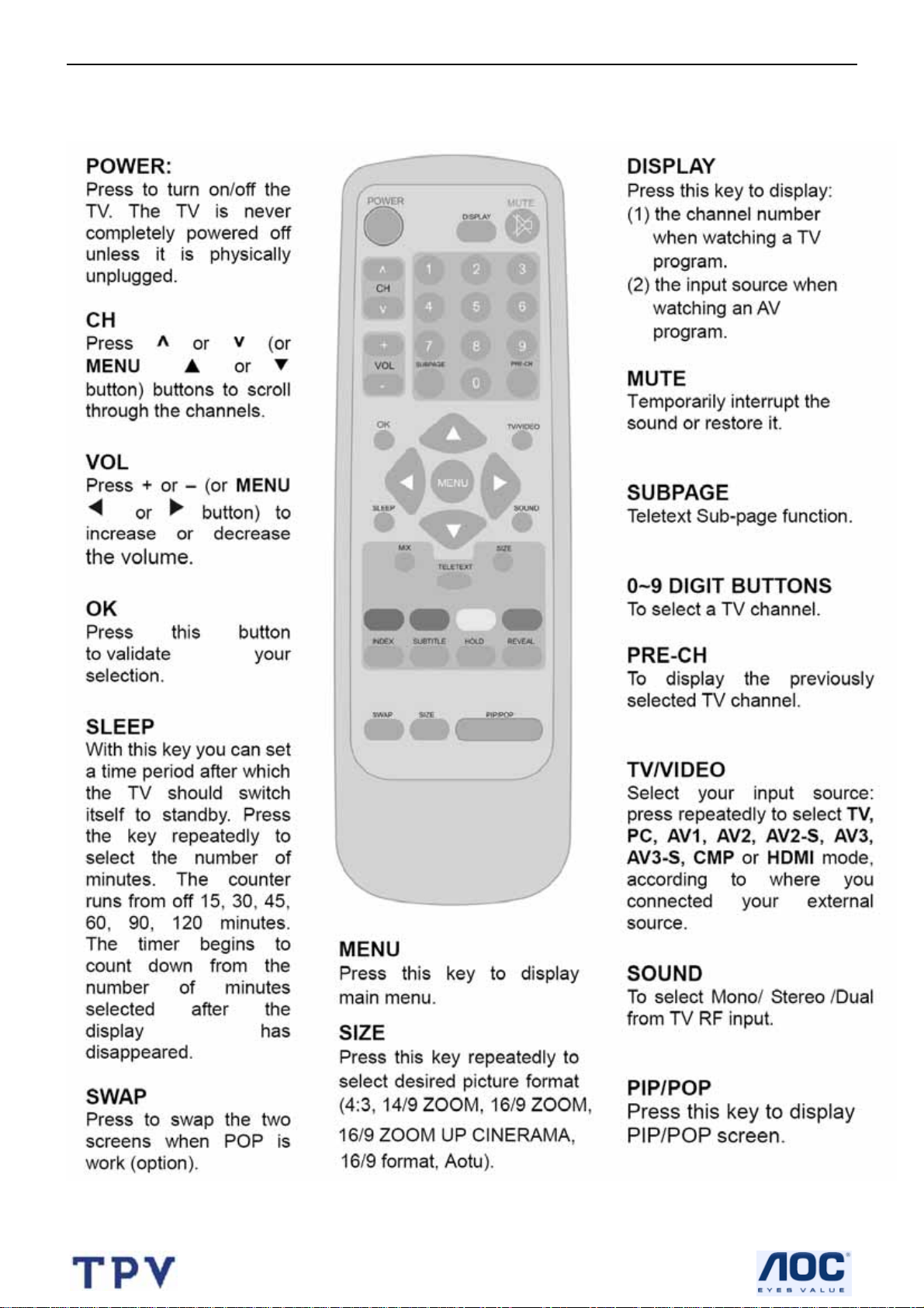
2.1 The Use Of Remote Control..……………...................5
2.2 The Use Of Teletext……..........…...........…...........6
2.3 Front Panel Control Knobs.…............……...............7
2.4 OSD Operations .………........................…............8
2.5 How To Connect ……..............……………............16
3 Input/Output Specification…………..........................20
3.1 Input Signal Connector……..........................20
3.2 RGB Input Signal Timing …….....……......................21
4. Mechanical Instructions…………………..................22
5. Repair Flow Chart ……………………….……….....26
6. White Balance Luminance Adjustment….…........32
7. PCB Layout ………….……………………....….......36
SAFETY NOTICE
ANY PERSON ATTEMPTING TO SERVICE THIS CHASSIS MUST FAMILIARIZE HIMSELF WITH THE
7.1 Main Board.……….......................................36
7.2 Power Board……..……..............................38
7.3 Key Board…...................................41
7.4 IR Board …................….......................41
7.5 DC-DC Board....…………...............................43
7.6 Earphone Board..…….....…..........................44
8. Block Diagram.…….........................................45
8.1 Main Board.………………………………..….45
8.2 Power Board…..…....………………….......46
8.3 Exploded View..……….....................…..47
9. Schematic Diagram………………………...48
9.1 Main Board………..………………………..48
9.2 Power Board.....…...................................60
9.3 Tuner Board...…….......................................62
9.4 Earphone Board………….………………….65
10. BOM List…......................................................66
CHASSIS AND BE AWARE OF THE NECESSARY SAFETY PRECAUTIONS TO BE USED WHEN SERVICING
ELECTRONIC EQUIPMENT CONTAINING HIGH VOLTAGES.
CAUTION: USE A SEPARATE ISOLATION TRANSFOMER FOR THIS UNIT WHEN SERVICING
1
Page 2
32’’ LCD TV Color Monitor AOC L32W451
Revision List
Version Release Date Revision Instructions TPV Model
A00 Aug.-10-2006 Initial Release EJF5MTNBC3A3TMP
E325MTNBW3AC2P
A01 Aug.-30-2006 Add TPV model in item 10
E325MTNLW3MGNP
A02 Oct.-31-2006 Add TPV model in item 10 E325MTNLW3MKNP
2
Page 3
32’’ LCD TV Color Monitor AOC L32W451
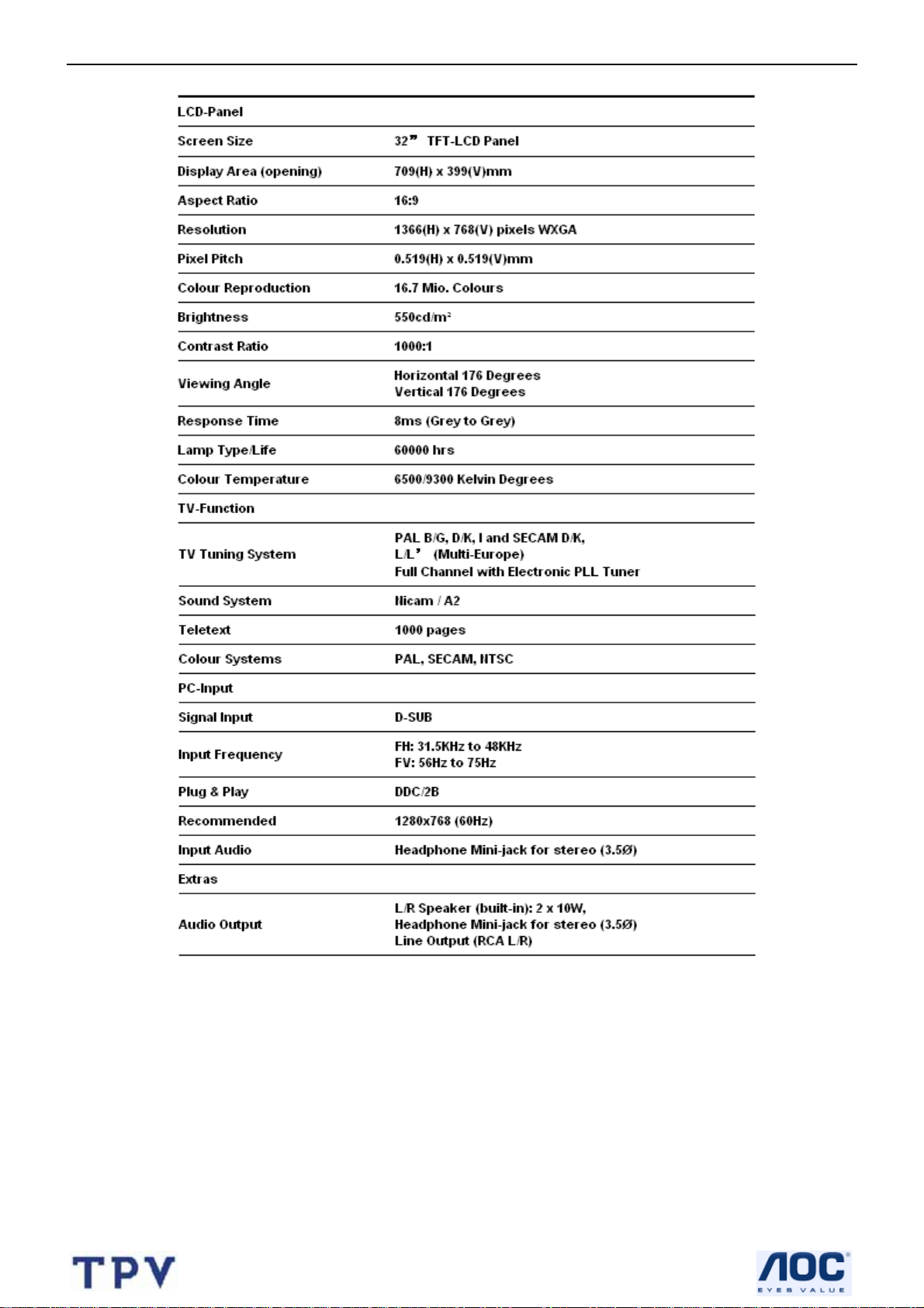
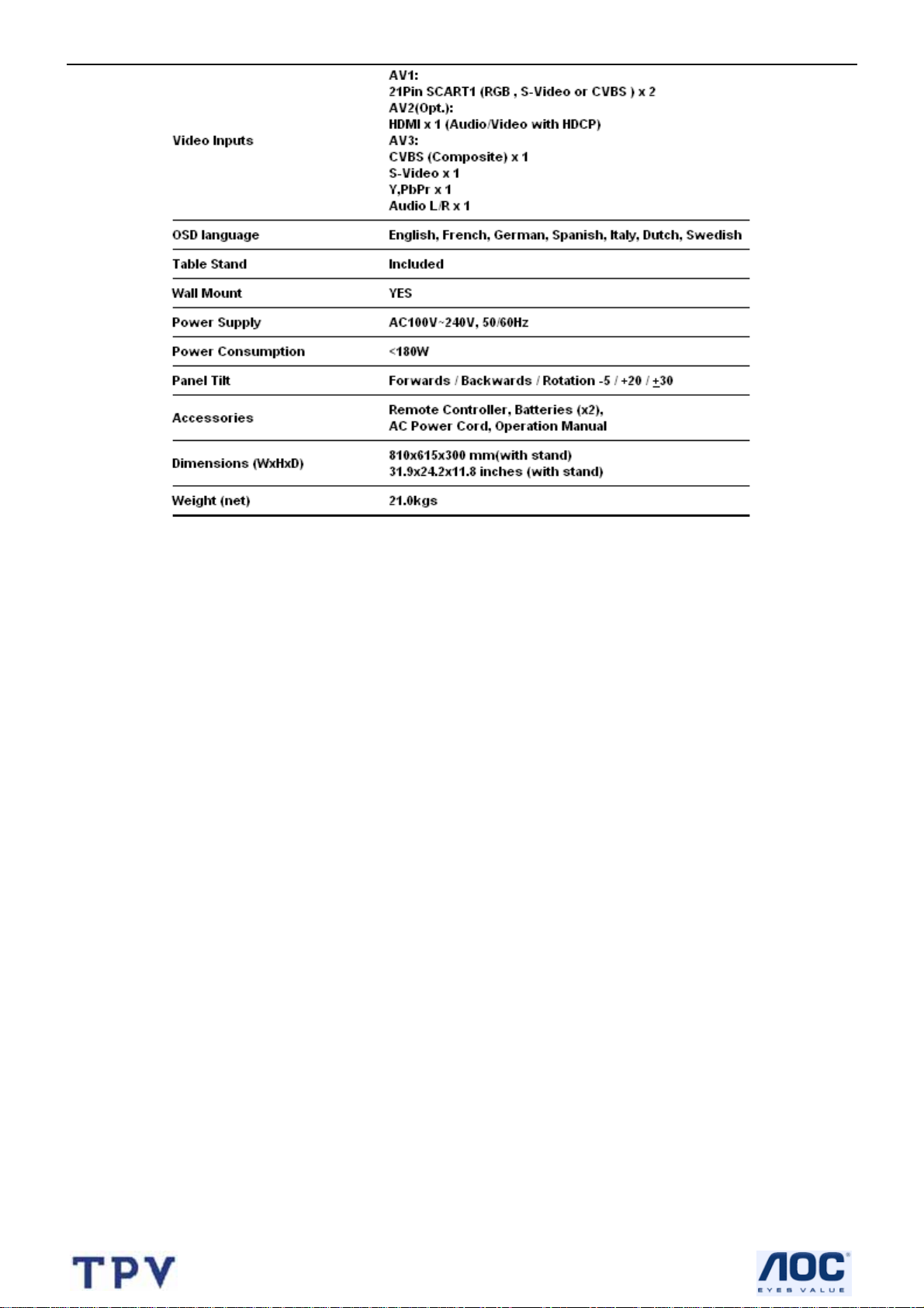
1. Monitor Specifications
3
Page 4
32’’ LCD TV Color Monitor AOC L32W451
4
Page 5
32’’ LCD TV Color Monitor AOC L32W451
2. Operations Instructions
2.1 The Use Of Remote Control
5
Page 6
32’’ LCD TV Color Monitor AOC L32W451
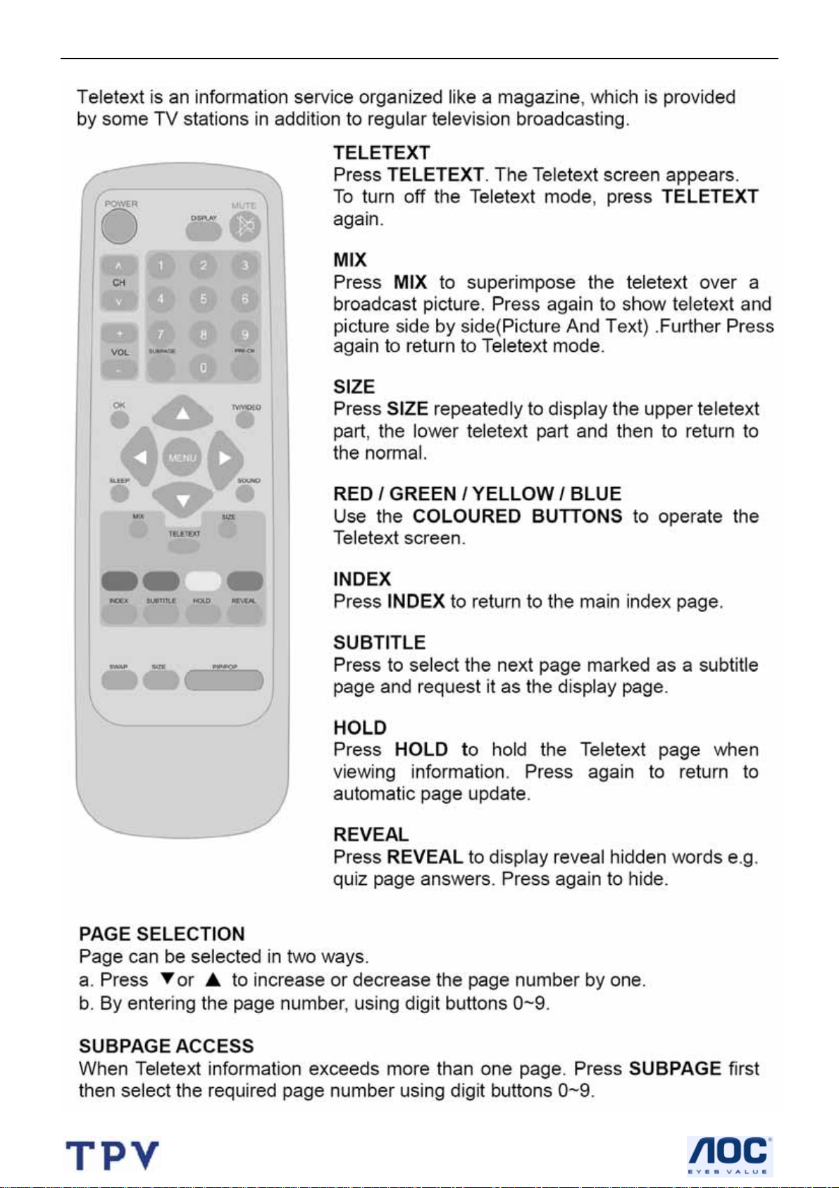
2.2 The Use Of Teletext
6
Page 7
32’’ LCD TV Color Monitor AOC L32W451
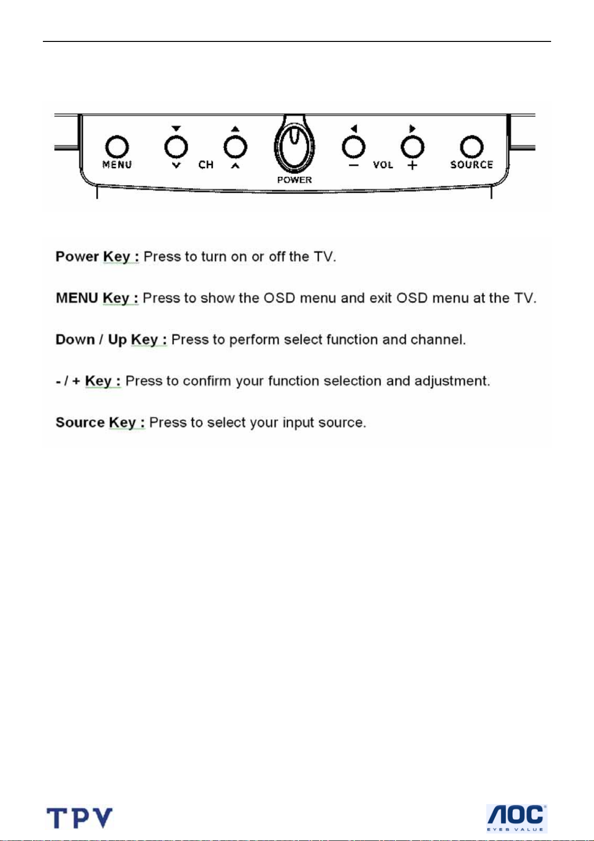
2.3 Front Panel Control Knobs
7
Page 8
32’’ LCD TV Color Monitor AOC L32W451
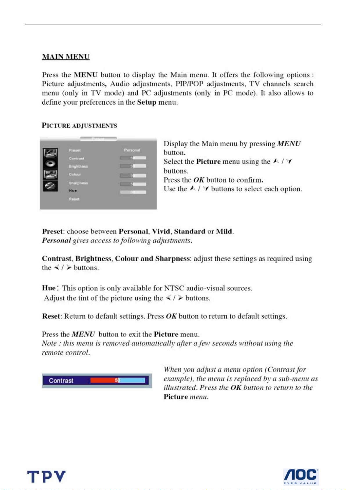
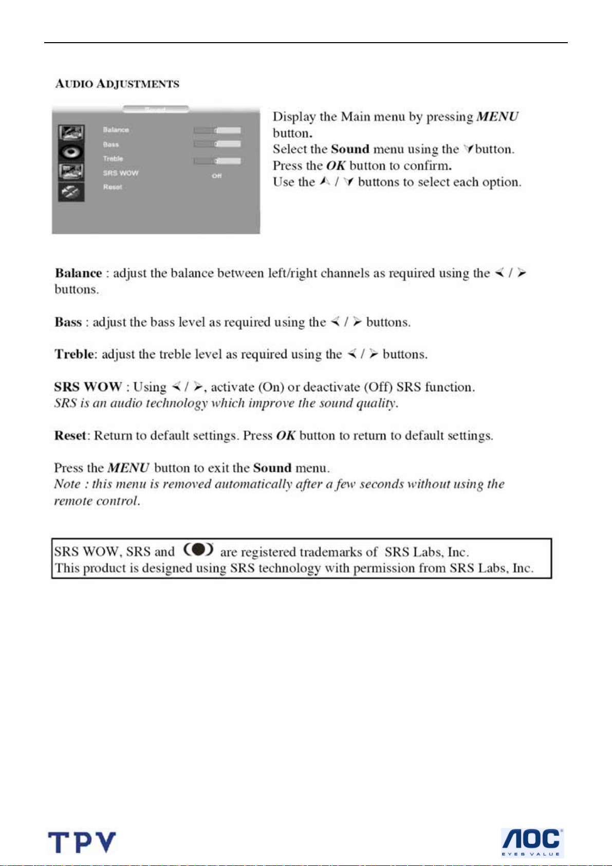
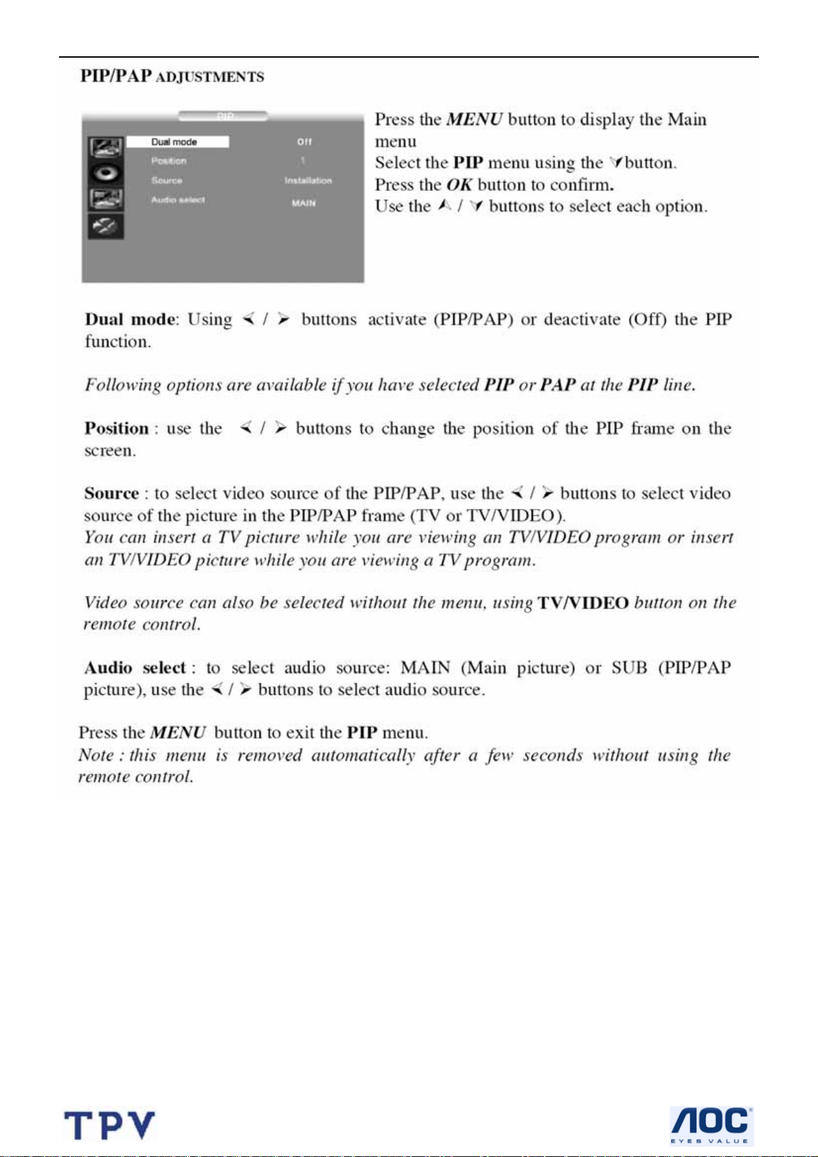
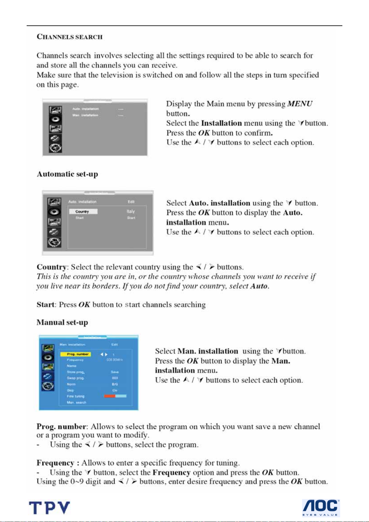
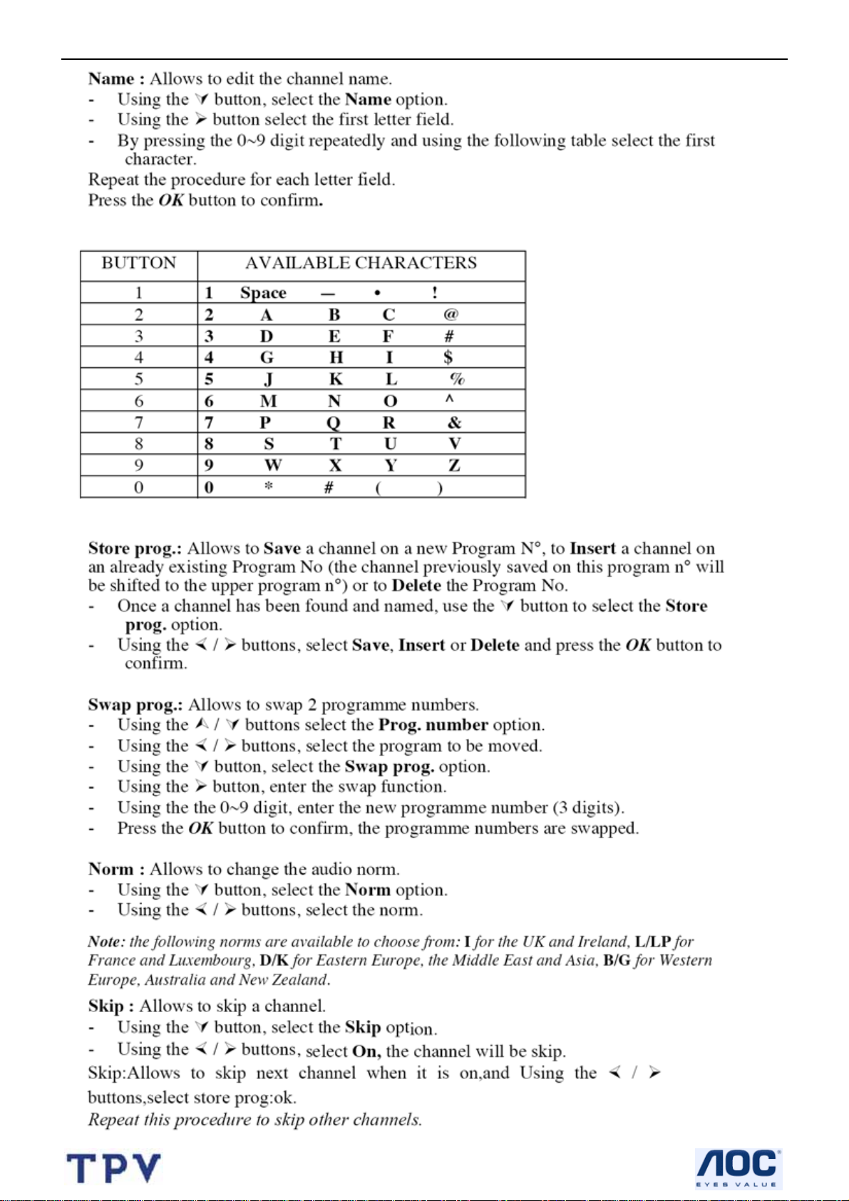
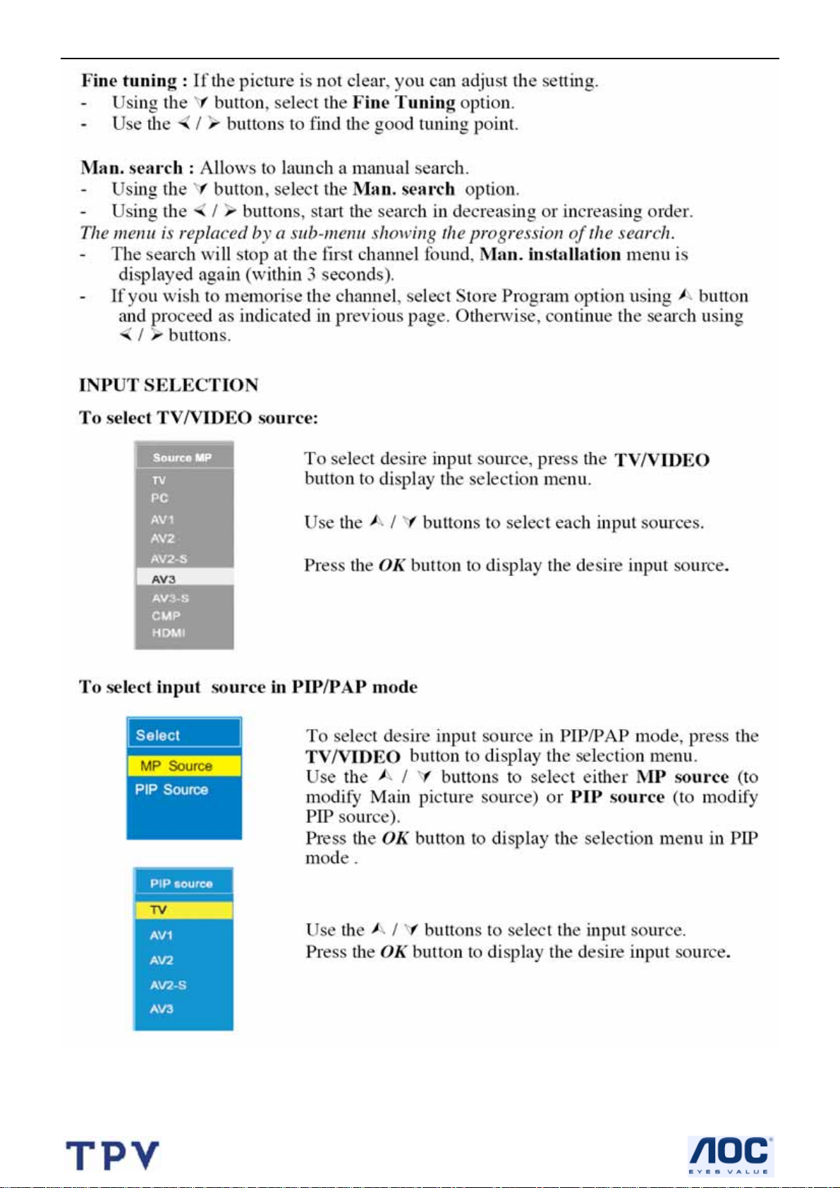
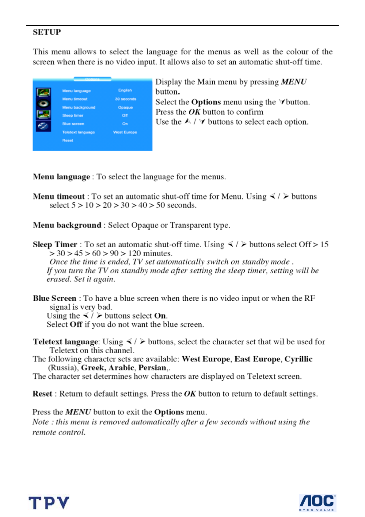
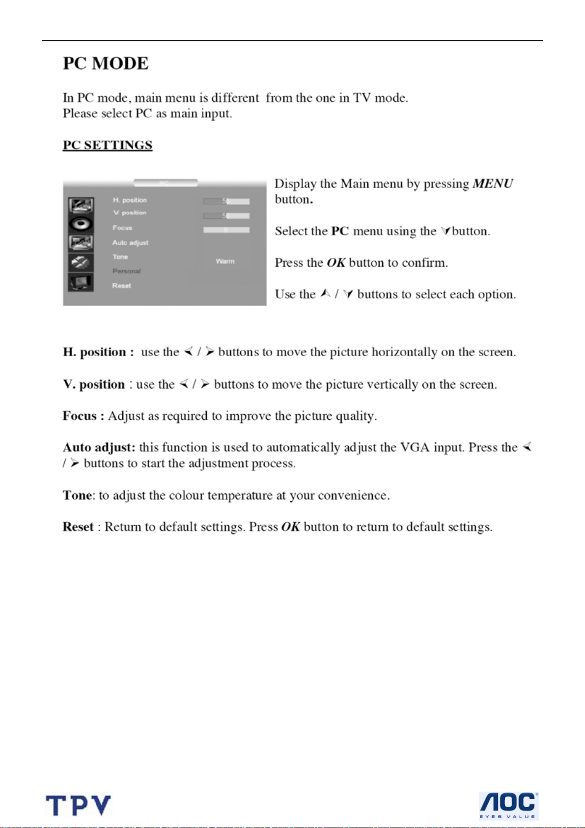
2.4 OSD Operations
8
Page 9
32’’ LCD TV Color Monitor AOC L32W451
9
Page 10
32’’ LCD TV Color Monitor AOC L32W451
10
Page 11
32’’ LCD TV Color Monitor AOC L32W451
11
Page 12
32’’ LCD TV Color Monitor AOC L32W451
12
Page 13
32’’ LCD TV Color Monitor AOC L32W451
13
Page 14
32’’ LCD TV Color Monitor AOC L32W451
14
Page 15
32’’ LCD TV Color Monitor AOC L32W451
15
Page 16
32’’ LCD TV Color Monitor AOC L32W451
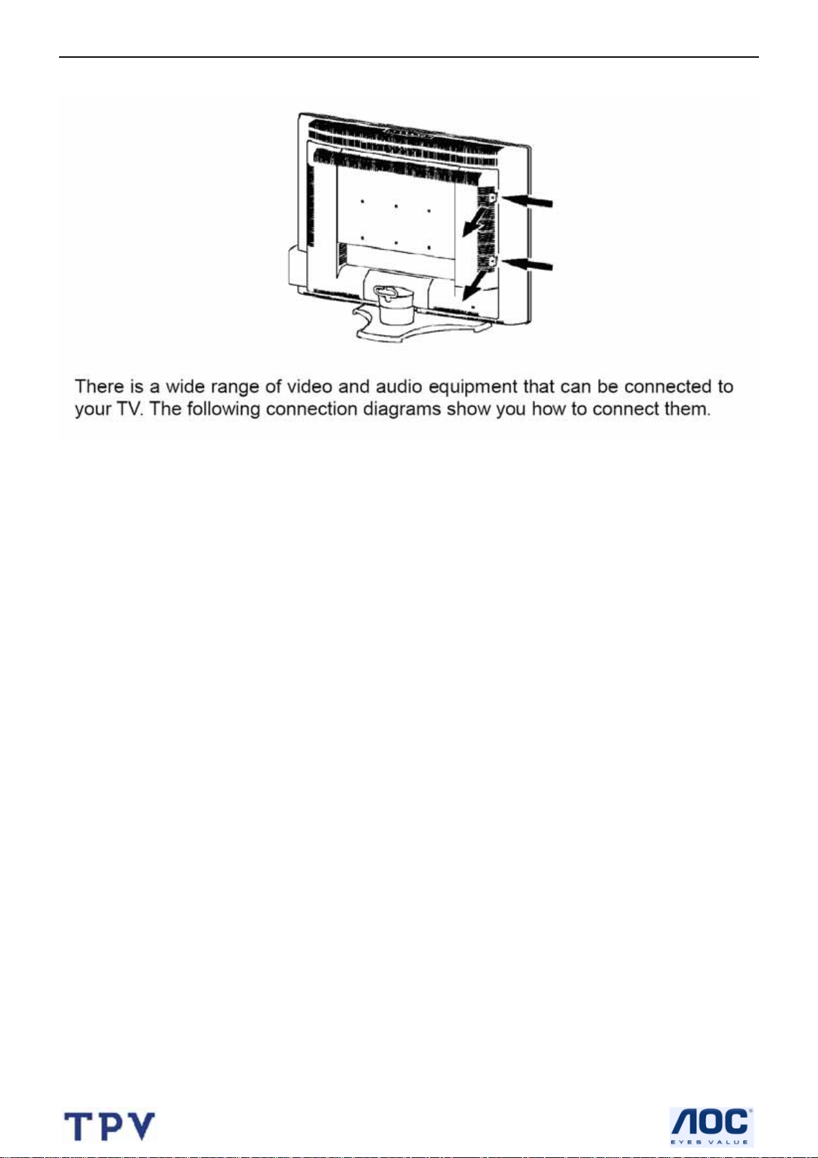
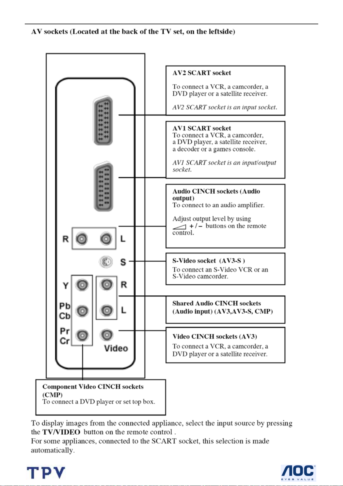
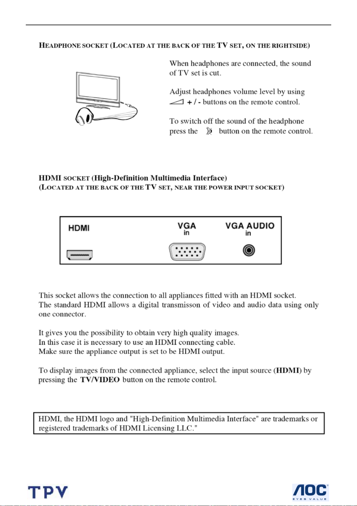
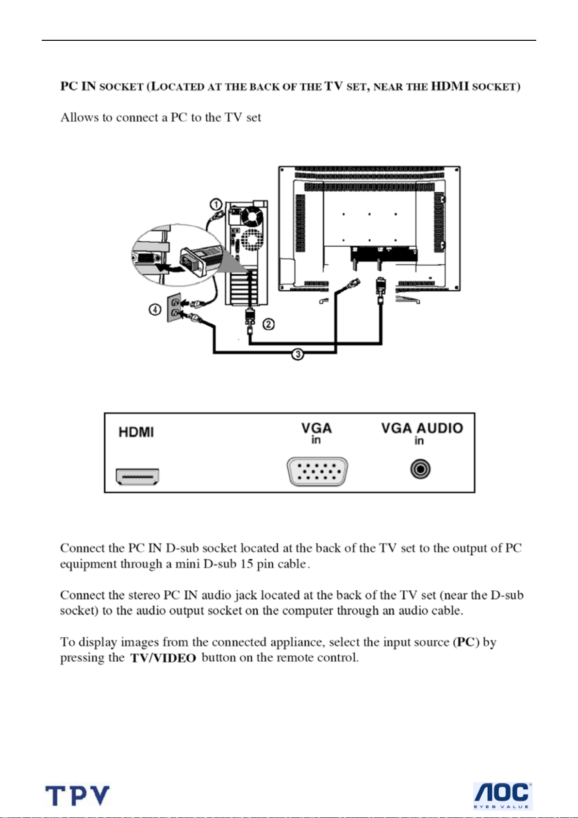
2.5 How to Connect
16
Page 17
32’’ LCD TV Color Monitor AOC L32W451
17
Page 18
32’’ LCD TV Color Monitor AOC L32W451
18
Page 19
32’’ LCD TV Color Monitor AOC L32W451
19
Page 20
32’’ LCD TV Color Monitor AOC L32W451
3. Input/Output Specification
3.1 Input Signal connector
This procedure gives you instructions for installing and using the LCD TV display.
Lay the display on the desired operation and plug the power cord into a convenient AC outlet. Three-wire p ower cord
must be shielded and is provided as a safety precaution as it connects the chassis and cabinet to the electrical
conduct ground. If the AC outlet in your location does not have provisions for the grounded type plug, the installer
should attach the proper adapter to ensure a safe ground potential.
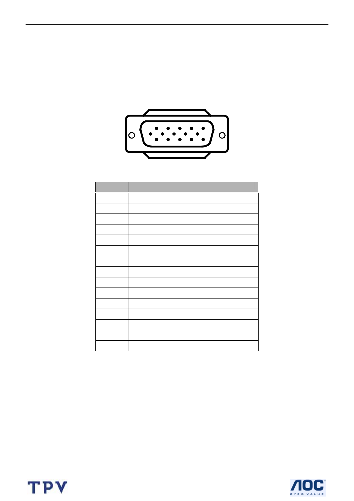
Connect the 15-pin D-SUB color display shielded signal cable to your signal sy stem device and lock both scre ws on
the connector to ensure firm grounding. The connector information is as follow:
1
6
11 15
5
10
15 - Pin Color Display Signal Cable
Pin No. Description
1 Red Video
2 Green Video
3 Blue Video
4 Not used
5 GROUND
6 Red Video Ground
7 Green Video Ground
8 Blue Video Ground
9 No Pin
10 Sync. Ground
11 Not used
12 Serial Data for DDC
13 Horizontal Sync.
14 Vertical Sync.
15 Serial Clock for DDC
Apply power to the display by turning the power switch to the "ON" position and allow about ten seconds fo r Panel
warm-up. The Power-On indicator lights "GREEN" when the display is on.
With proper signals feed to the display, a pattern or data should appear on the screen, adjust the brightness and
contrast to the most pleasing display, or press auto-adjust to get the best picture-quality.
This TV (with PC function) has power saving function following the VESA DPMS. Be sure to connect the signal
cable to the PC.
If your TV requires service, it must be returned with the power cord.
20
Page 21
32’’ LCD TV Color Monitor AOC L32W451
3.2 RGB Input Signal Timing
Horizontal Vertical Sync Polarity Presence Screen Mode
Dots × Lines
720×400 31.47 70.08
640×480 31.50 60.00
640×480 37.50 75.00
640×480 37.86 72.81
800×600 37.90 60.32
800×600 46.90 75.00
800×600 48.08 72.19
1024×768 48.40 60.00
1280×768 47.7 60
Frequency Frequency Horizontal Vertical Horizonta Vertical Normal FULL
(kHz) (Hz) (4:3) (16:9)
NEG POS YES YES YES YES
NEG NEG YES YES YES YES
NEG NEG YES YES YES YES
NEG NEG YES YES YES YES
NEG NEG YES YES YES YES
NEG NEG YES YES YES YES
NEG NEG YES YES YES YES
YES YES YES YES YES YES
YES YES YES YES YES YES
21
Page 22
32’’ LCD TV Color Monitor AOC L32W451
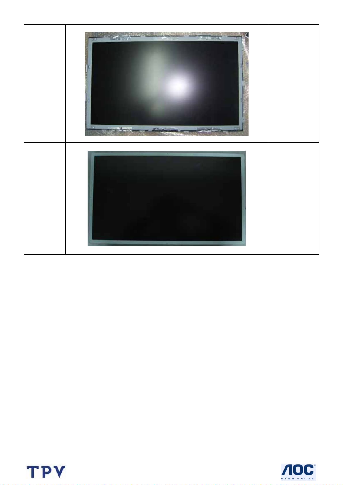
4. Mechanical Instructions
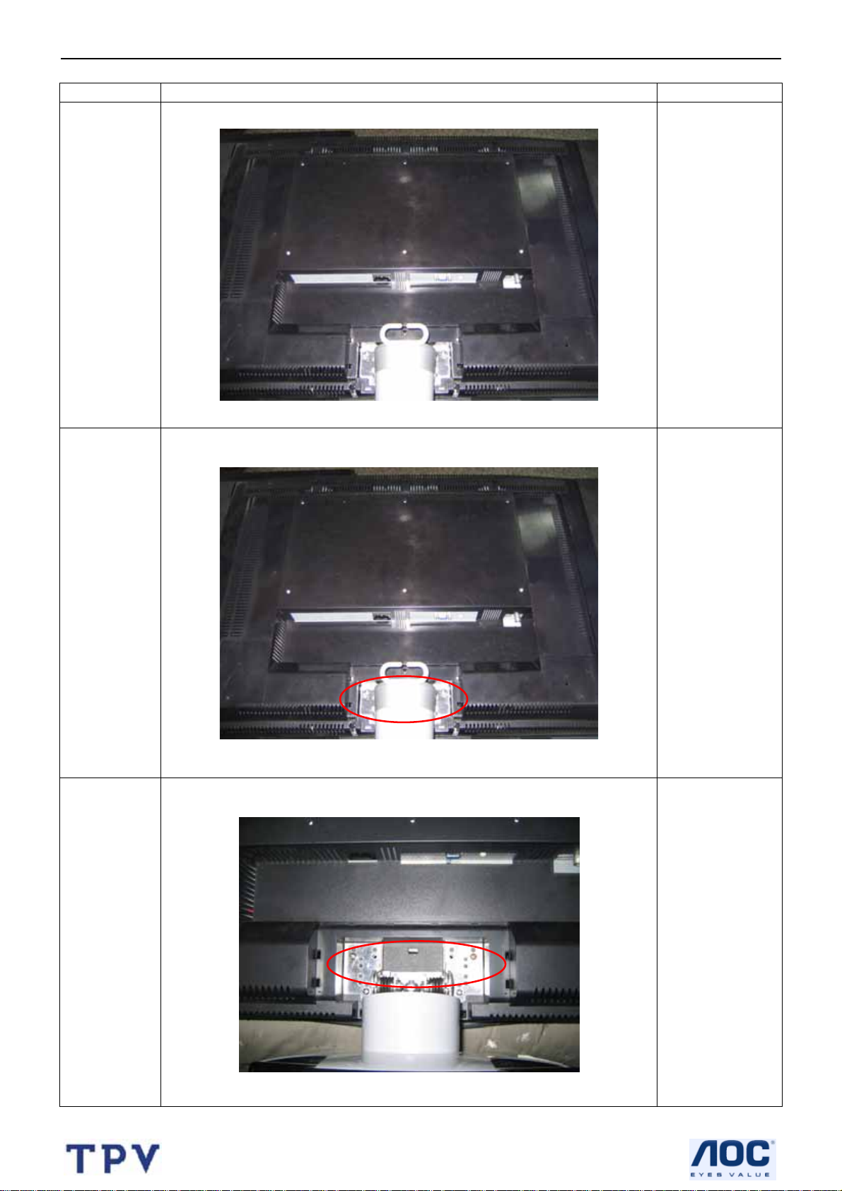
Step Figure Description
Lay the LCD-TV
Preparation
on a flat, soft and
clean surface.
Remove
the base
Remove
the stand
Remove the
hinge cover
Remove the
screws on the
stand to remove
the stand.
22
Page 23
32’’ LCD TV Color Monitor AOC L32W451
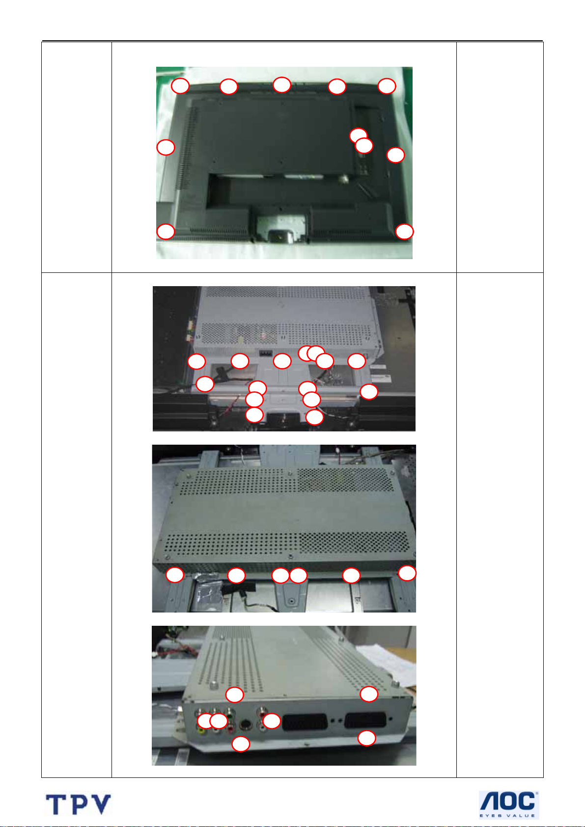
Remove the
Remove
the back
cover
screws mark in
red to remove the
back cover.
Remove
the shield
and plate
Remove the
screws to
remove shield
and plate.
23
Page 24
32’’ LCD TV Color Monitor AOC L32W451
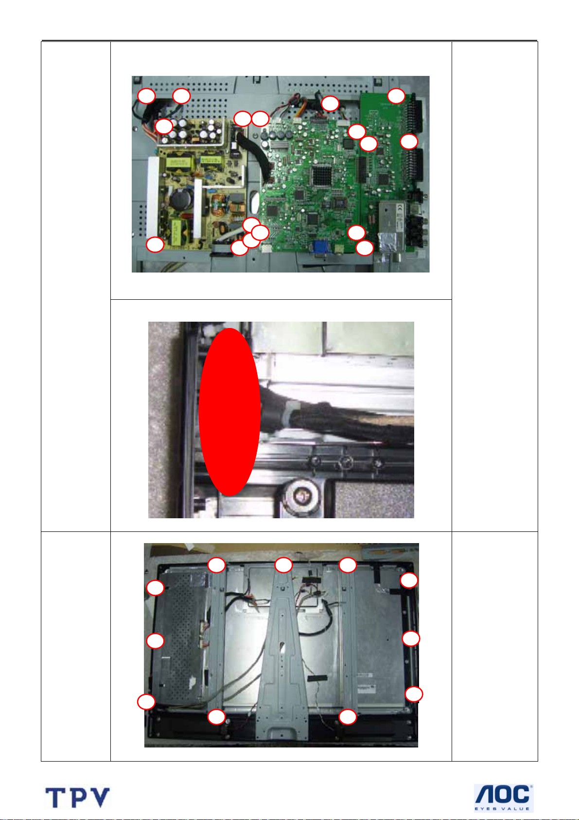
1.Remove the
screws marked in
red to remove the
main board,
power board and
tuner board.
Remove
power ,
tuner and
power
board,etc
2.Disconnect the
connector and
remove the tuner
board , power
board and main
board.
3. Remove the
screws and
connector to
remove the ir
board.
Remove
the plate
and the
bezel
Remove the
screws marked in
red to remove
plate and the
bezel.
24
Page 25
32’’ LCD TV Color Monitor AOC L32W451
Remove the
Remove
the frame
screws connect
with the panle to
remove frame.
The end
N/A
25
Page 26
32’’ LCD TV Color Monitor AOC L32W451
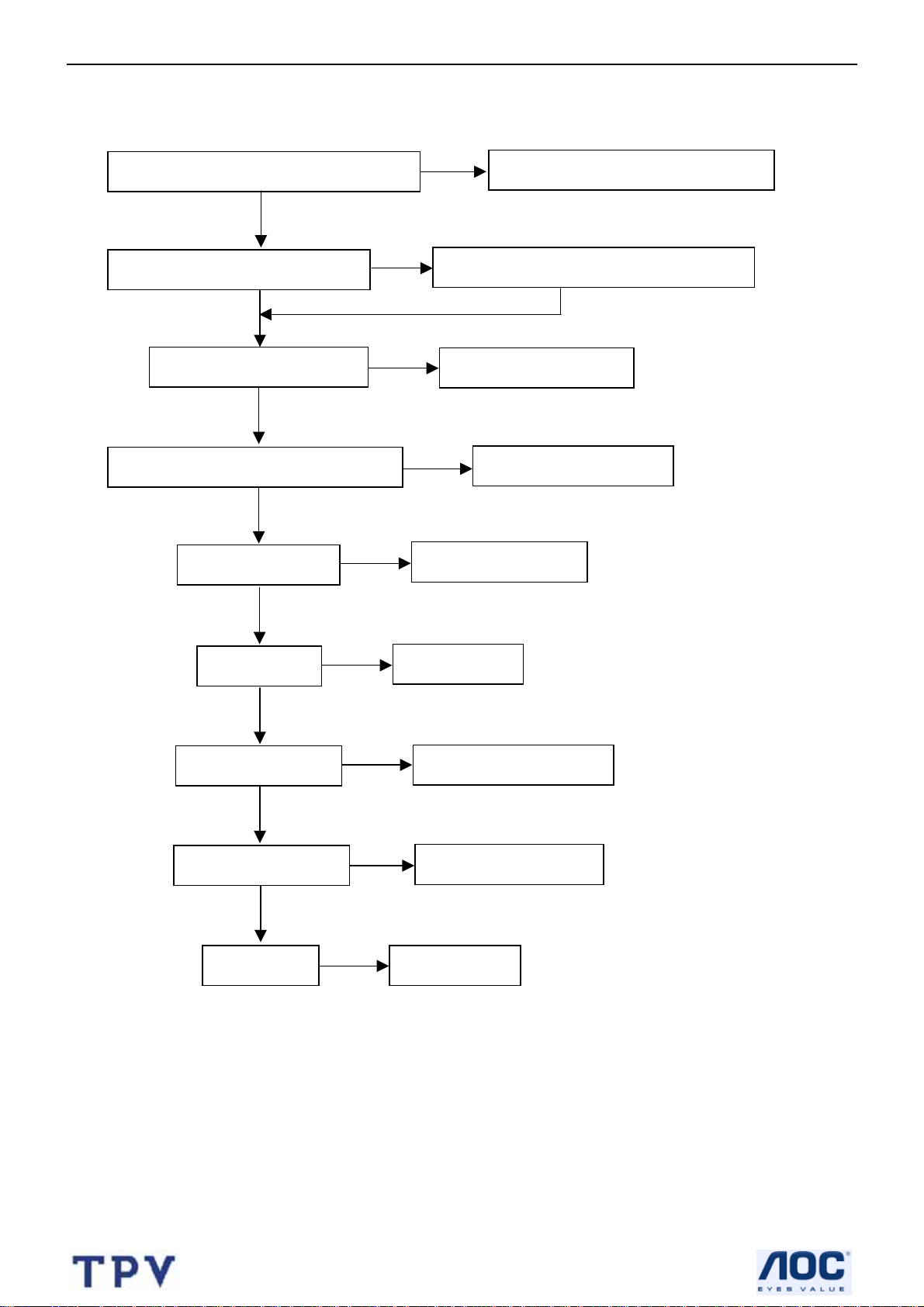
5. Repair Flow Chart
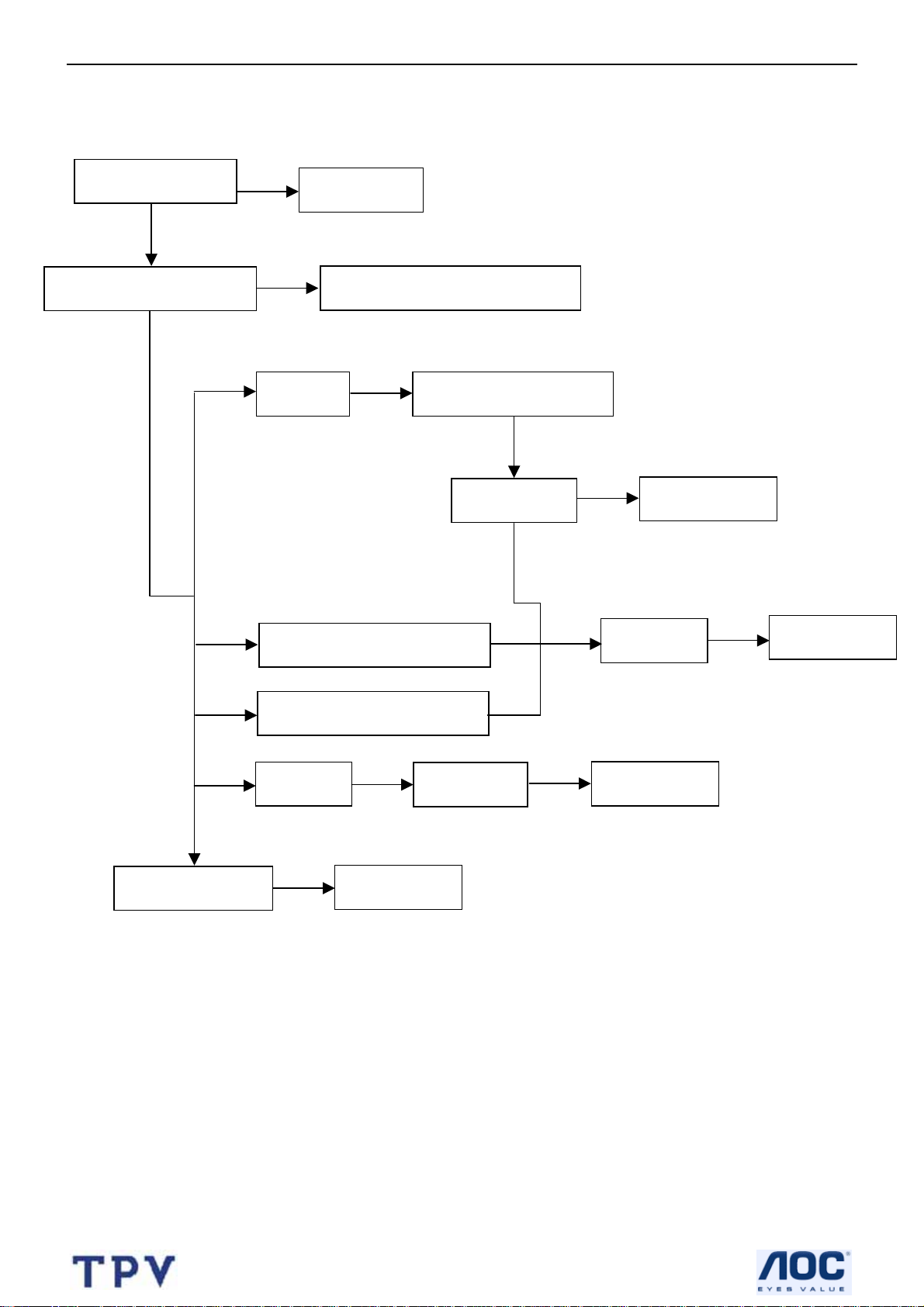
5.1 No Power (No LED indicator)
Check power cord and board interface
OK
Check F901, BD901, D901, D902
NG
OK
Check the load
Check IC981, D928 (12V)
NG
OK
Check Q924, IC924 (ON/OFF signal)
OK
Check IC941, Q941
NG
OK
Check T951
NG
OK
Check IC901, Q901
NG
OK
Check Q942, Q943
NG
OK
Check IC927
NG
NG
Replace F901 or BD901 or D910 or D902
Replace IC981or D928
NG
Replace IC941, Q941
Replace T951
Replace IC901 or Q901
Replace Q942 or Q943
Replace IC927
Plug in power cord and interface
Replace Q924 or IC924
26
Page 27
32’’ LCD TV Color Monitor AOC L32W451
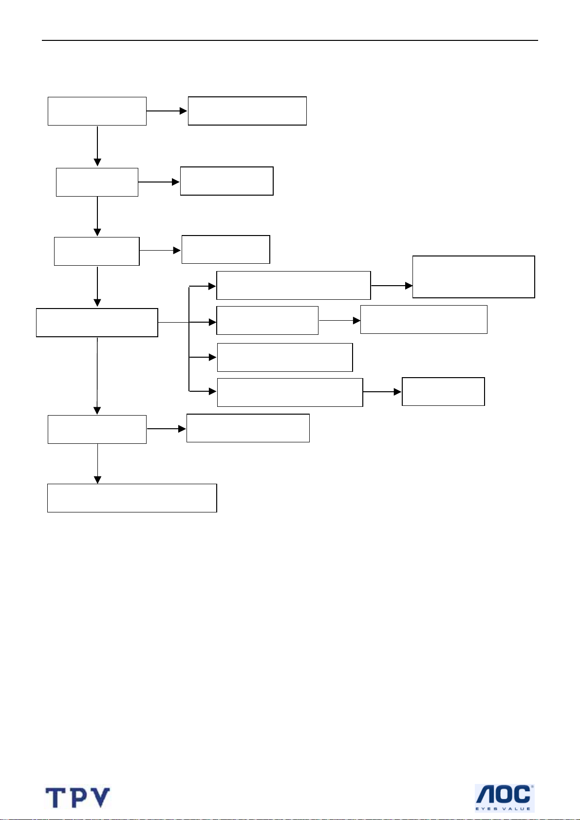
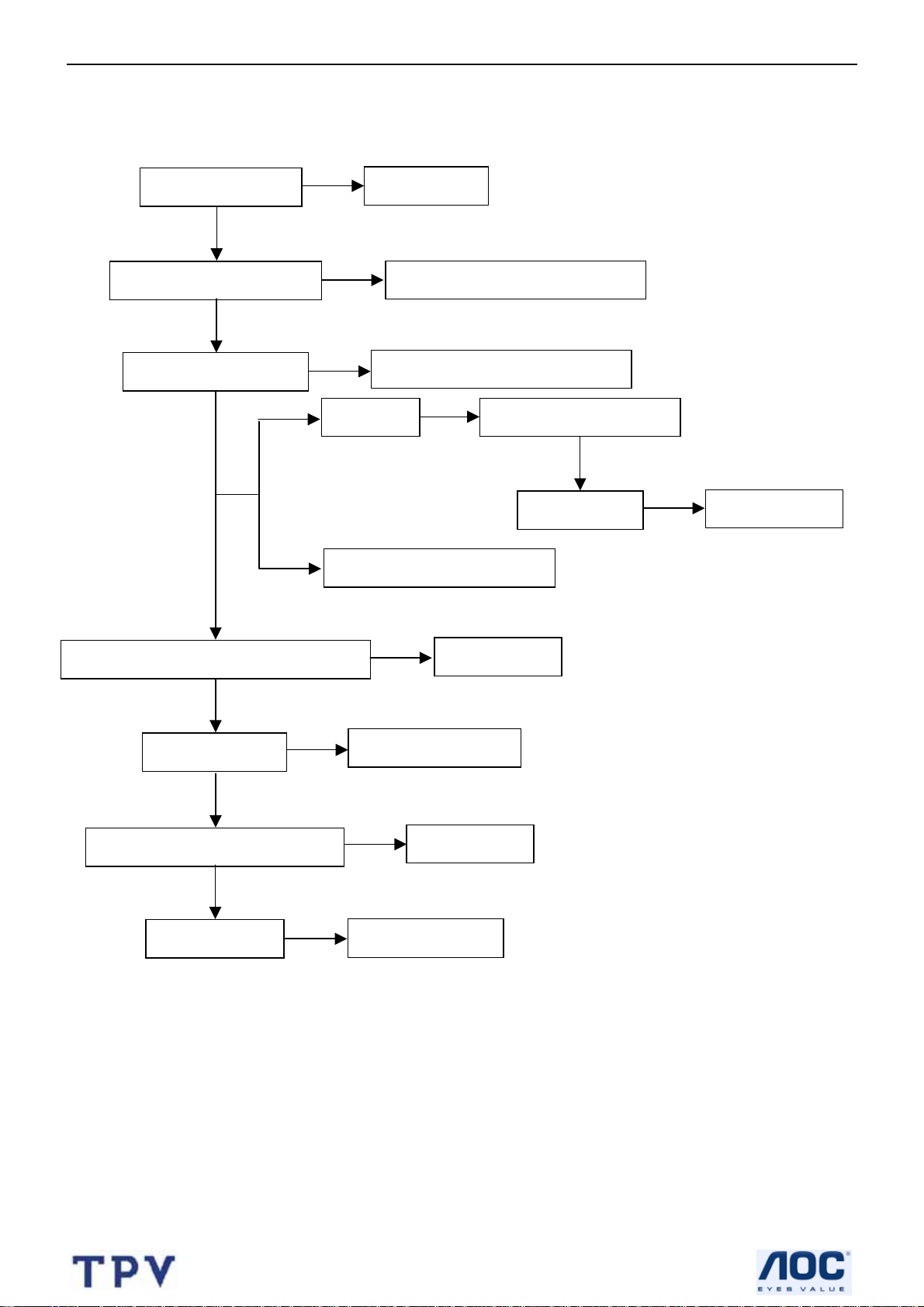
5.2 Can not start (LED indicator yellow)
Check key board
NG
Repair the key board
OK
Check 5V_SB
NG
Return to “5.1”
OK
Check 3.3V_SB
OK
NG
Replace U701
Check Q704, Q705, Q706, Q709
NG
Replace Q704 or Q705
or Q706 or Q709
Check PWR_ON signal
NG
Check U32, U21
NG
Replace U32 or U21
OK
Check I2C communication
Check Panel inverter board
NG
Replace panel
Check PFC circuit
NG
Replace IC901 or Q901
OK
Check main board power supply
27
Page 28
32’’ LCD TV Color Monitor AOC L32W451
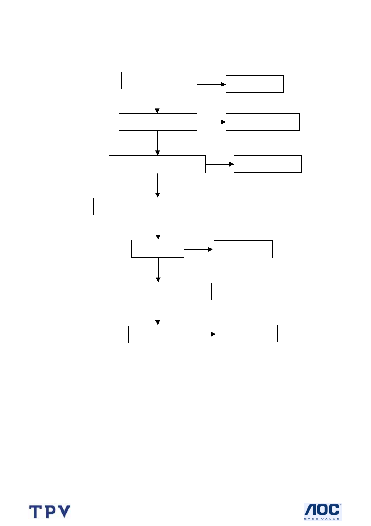
5.3 No display (LED indicator green)
Check the source
NG
Reset source
OK
Check LVDS cable
NG
Reset LVDS cable
OK
Check 24V power supply
NG
Return to “5.1”
OK
Check main board power supply
OK
Check U21
NG
Replace U21
OK
Check I2C communication
OK
Check panel
NG
Replace panel
28
Page 29
32’’ LCD TV Color Monitor AOC L32W451
5.4 Abnormal display
Check the source
NG
Reset source
OK
Check signal filter circuit
NG
Replace the filter or inductance
RF signal Check TV system setup
OK
OK
Check Tuner
NG
Replace Tuner
OK
AV, SCART1/2_CVBS signal
Check U3
NG
Replace U3
S-video SCART2_Y/C signal
OK
PC signal
Check U11
NG
Replace U11
Check U21, U20
NG
Replace U20
29
Page 30
32’’ LCD TV Color Monitor AOC L32W451
5.5 No sound
Check the source
Reset source
Check signal filter circuit
OK
NG
Replace the filter or inductance
Check Earphone jack
NG
Replace the Earphone jack
OK
SIF signal Check TV system setup
OK
Check Tuner
NG
Replace Tuner
AV, AIR1/AIR2, PC signal
Check Audio decoder MSP3410G U4
NG
Replace U4
OK
Check U63, U61
NG
Replace U63 or U61
OK
Check Amplifier MAX9714 U60
OK
Check speaker
NG
NG
Replace U60
Replace speaker
30
Page 31

32’’ LCD TV Color Monitor AOC L32W451
5.6 Key Board
OSD is unstable or not working
Is Key Pad Board connecting normally?
N
Connect Key Pad Board
Y
Is Button Switch normally?
N
Replace Button Switch
Y
Is Key Pad Board Normally?
N
Replace Key Pad Board
Y
Check Main Board
31
Page 32

32’’ LCD TV Color Monitor AOC L32W451
6. White Balance, Luminance Adjustment
Instrument List:
Chroma 2225、VG848、Chroma 7120
Adjustment Process:
① Instrument Orientation
Connect LCD-TV、Chroma 2225 and VG848, and set Timing137、Pattern1 on Chroma2225. Chroma7120’s lens
must aim at the center of Pattern1 showed on the LCD-TV’s screen. The distance of Chroma7120’s lens and the
center of screen is 20cm±1cm.
② ENTER FACTORY
After orientation OK, set Pattern104(black picture) on Chroma225.Press 1-9-9-9 on remote to enter the menu
on top left of the screen(refer to fig.1,this menu will show slowly), then from UP key(△) option to enter the menu
(refer to fig.2).
Fig.1
32
Page 33

32’’ LCD TV Color Monitor AOC L32W451
Fig.2
Fig.3
③ PC Mode White Balance Adjustment
Begin to adjust the W/B (White Balance) you should select the Color Temp(Warm and Cold) and enter the son
menu from father menu “Scaler” refer to Fig.2 and Fig.3.
Set channel color temperature value and brightness on Chroma712 0.Set 303 319 350(warm Temp) on CH3 and
278 289 350(cold Temp) on CH4.Press MODE key on Chroma7120 to switch xyY mode.
Use black sleeve on Chroma7120’s lens to ensure no external ray. Set Pattern104 on Chroma2225.Adjust
SCALAR RB、GB、BB value to make sure the brightness is the lowest, then set Pattern105 on Chroma2225 and
adjust RG、GG、BG value to make the value displaying on Chrom a7120 is about 100.Pre ss “Save” to save. Switch
to CH4, select cold Temp and then adjust it according to above method. Press “Save” to save.
④ AV MODE W/B ADJUSTMENT
Begin to adjust AV/COMPONENT YPbPr(480I/576I)/COMPONENT T -scaler(480P/720P/1080I) /HDMI W/B,
their Color Temp modes refer to Fig.4/5/6/7
33
Page 34

32’’ LCD TV Color Monitor AOC L32W451
Fig.4
Fig.5
Fig.6
34
Page 35

32’’ LCD TV Color Monitor AOC L32W451
Fig.7
1.OFFSET(26%) W/B ADJUSTMENT(This is only for AV/TV):Change the input signal to 26% white level
performance .Set the CHROMA7120 to 288 301 30 and MODE_RGB ,then adjust the TV’s RB、GB、BB to make
CHROMA7120 display to 100.
2.W/B ADJUSTMENT (100%): Change the input signal to 100% white level performance. Set the
CHROMA7120 to 288 301 415 and MODE_RGB , then adjust the TV’s RG、GG、BG to make CHROMA7120 display
to 100.
3.Save the adjustment. Then change the input signal to 26% white level performance. Set the CHROMA7120 to
MODE_RGB and CH3, check whether the color temperature was in SPEC (color spec is x±15;y±15;Y±15). In this
time, most of the TV is in SPEC, while the others should be adjusted twice or more to make its color temperature in
SPEC.
4.CHECK CUT OFF: Change the input signal to 0% white level performance. Firstly, press the “brightness” from
50% to 0% and make sure the Y is not changed. Secondly, change the input signal to 32 GRAYS performance and
make sure the grays is not connected at any position.( as the 5% level is between the first gray and the second gray.
5%=(1/32)*1.6。)
1.The white color temperature in PC Mode should be app.7200K(CIE1931: x=0.303, y=0.319,Y>350),
10300K(CIE1931 : x= 0.278, y= 0.289, Y>350 ).
2.The white color temperature in AV/TV Mode should be app. 8700K(CIE1931:x=0.288±15, Y=0.301±15,
Y>370). In this Mode,we should check the black balance,which level is 26% of the white level(1.0Vpp).
3. The white color temperature in HDTV/HDMI Mode should be app. 8700K(CIE1931:x=0.288±15, Y=0.301±15,
Y>370)
Those three channels should be factory preset and not be possible to be modified.
The measurement position is the center of the display(5) at brightness set to center and
Contrast set to max. . The tolerance of the color coordinates should be less than ± 0.015
35
Page 36

32’’ LCD TV Color Monitor AOC L32W451
7. PCB Layout
7.1 Main Board
36
Page 37

32’’ LCD TV Color Monitor AOC L32W451
37
Page 38

32’’ LCD TV Color Monitor AOC L32W451
7.2 Power Board
0
38
Page 39

32’’ LCD TV Color Monitor AOC L32W451
39
Page 40

32’’ LCD TV Color Monitor AOC L32W451
40
Page 41

32’’ LCD TV Color Monitor AOC L32W451
7.3 Key Board
7.4 IR Board
41
Page 42

32’’ LCD TV Color Monitor AOC L32W451
42
Page 43

32’’ LCD TV Color Monitor AOC L32W451
7.5 DC-DC Board
43
Page 44

32’’ LCD TV Color Monitor AOC L32W451
7.6 Earphone Board
44
Page 45

32’’ LCD TV Color Monitor AOC L32W451
8. Block Diagram
8.1 Main board
ANT
SCART1 (CVBS)
SCART2 (CVBS/Y/C)
AV (CVBS)
S-VIDEO
All mode Audio
HDMI
Component
VGA RGB
SCART1 (RGB)
Sil9011
Philips
Tuner
Panasonic Selector
AN15857A
Audio
Video(24bits R/G/B)
32” TV Main Board
Key PAD Board M30620SP
GP
CPU
IR/LED Board
CVBS
Y/C
Audio
SAA7117A
Video Decoder
EX52 Scalar
De-interlace
EM6A9320BI-5MG
Flash memory
A29040BL
Trident
OSD
TxT/CC
DDR
DC Output
AC 110/240 V
27/32”
Panel
Inverter
Power
Board
(Built in)
45
MSP3410G
Audio Decoder
PT2308S
Headphone driver
Earphone Speaker
MAX9704
AMPLIFIER
Page 46

32’’ LCD TV Color Monitor AOC L32W451
8.2 Power Board
32” TV Power Board
46
Page 47

32’’ LCD TV Color Monitor AOC L32W451
8.3 Exploded View
47
Page 48

32’’ LCD TV Color Monitor AOC L32W451
9. Schematic Diagram
9.1 Main Board
5V_SB
3
D106
BAV99
1 2
MLL5232B 5.6V
D109
D107
BAV99
3
1 2
EFF5MTNBC2THT
AOC (Top Victory) Electronics Co., Ltd.
Title
DVI/HDMI_MUX
Size Document Number Rev
A4
Date: Sheet
Wednesday, January 04, 2006
TV2765W-4E
715T1616-E
1
12
of
1.0
P10
SHELL1
DATA2-
DATA2+
DATA2/4_SHLD
DATA4-
DATA4+
DDC_CLK
DDC_DATA
A_VSYNC
DATA1-
DATA1+
DATA1/3_SHLD
DATA3-
DATA3+
+5V
GND
H_PLUG_DET
DATA0-
DATA0+
DATA0/5_SHLD
DATA5-
DATA5+
CLK_SHLD
CLK+
CLK-
A_RED
A_GREEN
A_BLUE
A_HSYNC
A_GND1
SHELL2
DVI_V
C125 0.1uF
U12
24LC02MWN
1
NC
VCC
2
NC
VCLK
3
NC
SCL
4 5
VSS SDA
R136 1K
5V
D108
BAV70
C132
0.1uF
31
1
2
3
4
5
6
7
8
9
10
11
12
13
14
15
16
17
18
19
20
21
22
23
24
C1
25
C2
26
C3
27
C4
28
C5
29
32
8
7
6
DVCC
1
DVCC
3
2
D5V
4.7K
R129
R147 10K
4.7K
R130
DVI = Option
48
Page 49

32’’ LCD TV Color Monitor AOC L32W451
1 2
FB11
FB10 150 OHM
1 2
ZD10
MLL752A
VGAHS6,12
VGA_SDA
VGA_SCL
VGAVS
C115
0.047uF
VGAHS
C123
0.047uF
R101
NC
150 OHM
VGAVS6,12
C107
100pF
R113 10K
R114 10K
3.3V_SB
R102
NC
RxD
VGA_SDA_IN
VGA_HS
VGA_VS
VGA_SCL_IN
ZD11
R10622
R10722
MLL752A
VGAHS
VGAVS
C108
47pF
3
D104
BAT54S
3
D105
BAT54S
VGA_VS
U10 24LC02
8
VCC
5
SDA
6
SCL
4
GND
I2C Address: 1010 000x
8-pin, 300mil DIP with socket
3.3V_SB
2
1
R122
1M
3.3V_SB
2
1
R125
100K
P11
DB15
1617
GG
11
12
13
14
15
5V
R115 NC
VCLK
NC2
NC1
NC0
0.47uF/50V
0.47uF/50V
C117
C124
7
3
2
1
1
1
10
6
1
7
2
8
3
9
4
5
BAT54C
11
12
13
14
15
R120 180K 1/16W
R124 180K 1/16W
6
1
7
2
8
3
9
4
10
5
D100
23
Q12
PMBS3906
23
Q14
PMBS3906
1
2
3
C113 0.1uF
R116 1K
1
1
TxD
32
Q11
PMBS3904
32
Q13
PMBS3904
R10375
D101MLL4148
FB
3.3V_SB
Detect_VGAVS 6
To mcu
Detect_VGAHS 6
R10475
D102MLL4148
1 2
1A 1Y
3 4
2A 2Y
5 6
3A 3Y
9 8
4A 4Y
11 10
5A 5Y
13 12
6A 6Y
C112
U11
0.1uF
P12
PC_AUDIO
R10575
74LVC14
GNDVCC
74LVC14
SCART1_FB
2
3
4
5
1
R148 0 1/16W
R149 0 1/16W
R150 0 1/16W
D103MLL4148
714
C114
0.1uF
R121 2.2K
R108 NC
R109 22
R110 NC
R111 22
R112 1K
32
1
PMBS3904
L104 600 OHM
L100
600 OHM
C111
0.1uF
3.3V_SB
R119
2.2K 1/16W
Q10
VGA_RIN 4
VGA_GIN 4
VGA_BIN 4
VGA_HSIN 4
VGA_VSIN 4
SC1_FB 4
DET_FB 6
TxD
RxD
FB
C116
0.1uF
C122
0.001uF
C100
0.001uF
Jan.04-2006
PCR
PCL
U16 74HC4052D
13
X
3
Y
GND
8
CN13
CONN
NC
X0
X1
X2
X3
Y0
Y1
Y2
Y3
A
B
EN
VEE
VDD
10uF/16V
1
2
3
C102
12
14
15
11
1
5
2
4
10
9
6
7
16
12VSW
HDMI_R7
HDMI_L7
S/PDIF7
SCART1_FB8
COMP_Y4
COMP_B4
COMP_R4
SCART_G8
SCART_B8
SCART_R8
5V_SB
+
R100 0 1/10W
5VSW
SC16,7,12
SD16,7,12
TX 6
SC1 6,7,12
RX 6
SD1 6,7,12
ISP_SW 6
C142 0.1uF
C143 0.1uF
REMOTE6,12
3.3V_SB
ST5V
6,12
KEY_AD
5V_SB
ST5V
MAIN-ON 12
2
4
6
8
10
12
14
16
18
20
22
24
26
28
CN10 I/O
1
3
5
7
9
11
13
15
17
19
21
23
25
27
2930
3132
3334
3536
PCR
PCL
SRS_R 9
SRS_L 9
FUN_1 6,8
FUN_2 6,8
GSOG 8
CVBS1 4
CVBS2 8
SAAY 8
SAAC 8
EX_Y 4
EX_C 4
Power Connect
0.1uF
0.1uF
C109
R118 1K
C144 100pF
C110
1
2
3
4
5
6
7
8
9
10
11
12
CN11
CONN
1
2
3
4
5
6
7
8
C1200.1uF
C1210.1uF
CN12
CONN
+20V
+12VP
+5VP
INV_PRO6
BL_ADJ3,6
5V
ST5V
R123
NC
0
R155
L101 600 OHM
L102 600 OHM
R117 1K
5V
L103 600 OHM
18
2
7
3
6
4
5
LP10
300 OHM
C118100pF
C1190.1uF
AOC (Top Victory) Electronics Co., Ltd.
Title
Size Document Number Rev
Custom
Wednesday, January 04, 2006
Date: Sheet of
I/O
TV2765W-4E
2
1
12
49
Page 50

32’’ LCD TV Color Monitor AOC L32W451
U22
Extra SRAM
VDDMQ
0.1uF
C285
0.1uF
C277
0.1uF
C286
0.1uF
C278
MD0
MD1
MD2
MD3
MD4
MD5
MD6
MD7
MD8
MD9
MD10
MD11
MD12
MD13
MD14
MD16
MD17
MD18
MD19
MD20
MD21
MD22
MD23
MD24
MD25
MD26
MD27
MD28
MD29
MD30
MD31
DQM0
DQM1
DQM2
DQM3
MCU_A[0..7]6
DQS[0..3]5
MA[0..11]5
C276
0.1uF
VDDMQ
C284
0.1uF
MD[0..31]5
DQM[0..3]5
C279
0.1uF
C287
0.1uF
SVP-EX52_256
U21A
73
MD0
75
MD1
76
MD2
78
MD3
84
MD4
86
MD5
88
MD6
90
MD7
91
MD8
93
MD9
94
MD10
96
MD11
102
MD12
104
MD13
106
MD14
108
MD15
148
MD16
150
MD17
152
MD18
154
MD19
160
MD20
162
MD21
163
MD22
165
MD23
166
MD24
168
MD25
170
MD26
172
MD27
178
MD28
180
MD29
181
MD30
183
MD31
79
DQM0
97
DQM1
159
DQM2
177
DQM3
C280
0.1uF
C288
0.1uF
VDDMQ
179
VDDM
175
82
C289
0.1uF
171
VDDM
DQS0
100
DQS1A4DQS0
C281
0.1uF
161
VDDM
DQS1
156
DQS2
157
VDDM
DQS2
174
DQS3
C283
C282
0.1uF
0.1uF
C290
C291
0.1uF
0.1uF
153
136
134
124
119
VDDM
VDDM
VDDM
103958577173
99
VDDM
VDDM
VDDM
VDDM
VDDM
VDDM
VDDM
VDDM
VDDM
176
VSSM
169
VSSM
155
VSSM
158
VSSM
SVP-EX [256]
(1 of 2)
DQS3
MA11
MA10
MA9
MA8
MA7
MA6
MA5
MA4
MA3
MA2
MA1
MA0
ADDR7
109
111
112
114
115
117
118
120
122
123
125
126
212
213
RN212
MA5
MA4
MA3
MA2
MA1
100
MA0
3 6
4 5
MCU_A7
MCU_A6
MA11
MA10
MA9
MA8
MA7
MA6
151
132
VSSM
VSSM
ADDR5
ADDR6
210
211
1 8
2 7
MCU_A4
MCU_A5
129
121
VSSM
VSSM
ADDR3
ADDR4
208
209
3 6
4 5
MCU_A3
MCU_A2
116
105
VSSM
VSSM
VSSM
ADDR0
ADDR1
ADDR2
206
207
RN213
100
1 8
2 7
MCU_A0
MCU_A1
98
10187838180
VSSM
VSSM
130
VSSM
MCK0
131
VSSM
VSSM
MCK0#
CS0#
133
VDDMQ
139
CS1#
135
137
C293
0.1uF
141
VDDR
RAS#
138
VSSR
CAS#
140
192
NC
MVREF
193
191
190
MPUGPIO2
MPUGPIO0
MPUGPIO1
FLD/IO
MPUCS0N
TESTMODE
R216 10K
MPUGPIO1
MPUGPIO4
189
188
MPUGPIO3
MPUGPIO4
P_17
SDA
SCL
A_D7
A_D6
A_D5
A_D4
A_D3
A_D2
A_D1
A_D0
RD#
WR#
ALE
INT#
V5SF
RESET
BA1
BA0
CLKE
WE#
MVREF 5
CAS# 5
RAS# 5
CS0# 5
MCLK0# 5
MCLK0 5
17
18
16
14
203
202
201
200
197
196
195
194
216
217
218
219
220
15
12
13
147
145
144
142
5V
CS 6
EX-PWM
SDA_EX
SCL_EX
R223 470
BA1 5
BA0 5
CLKE 5
WE# 5
R219
1K 1/16W
RN210 100
1 8
2 7
3 6
4 5
1 8
2 7
3 6
4 5
RN211
RD_EMU 6
WR_EMU 6
ALE_EMU 6
INT# 6
MPUCS0N
MPU has
separated
Address/Data
I2C Address:
7C/7D
Not
Populated
C295
22uF/16V
100
VDDM
R217
MPUCS0N
R224
NC
MCU_A[0..7]6
4.7K 1/16W
R220
10K 1/16W
R225
10K
VD3_3
A[8..14]6
Q20
PMBS3904
1
AD7
AD6
AD5
AD4
AD3
AD2MD15
AD1
AD0
RST_H 6
MPU has
Data/Address
multiplex
I2C Address:
7E/7F
A[0..7]
A[8..14]
5V
R218
4.7K 1/16W
2 3
5V_SB
0.1uF
C298
MPUGPIO4
CS16
RD#6
WR#6
C294
0.1uF
AD[0..7] 6
R226
0
A0
A1
A2
A3
A5
A6
A7
A8
A9
A10
A11
A12
A13
A14
BL_ADJ 2,6
MPUGPIO1
AS7C256A
AD0
11
D0
D1
D2
D3
D4
D5
D6
D7
VCC
GND
R221
R222
*CS1N is not a input or output pin
CS1N=0: SVP-EX CPU access enabled
CS1N=1:SVP-EX CPU access disabled
Connector for Amtel AT76C112 Video Output
12
13
15
16
17
18
19
28
14
68 1/16W
68 1/16W
AD1
AD2
AD3
AD4
AD5
AD6
AD7
C296
68pF
10
A0
9
A1
8
A2
7
A3
6
A4
5
A5
4
A6
3
A7
25
A8
24
A9
21
A10
23
A11
2
A12
26
A13
1
A14
20
/CE
22
/OE
27
/WE
C297
68pF
INPUT
MPUGPIO0
0
0
11
1
MPUCS0N
0
1
0
1
0
1
1
AOC (Top Victory) Electronics Co., Ltd.
Title
Size Document Number Rev
B
Wednesday, January 04, 2006
Date: Sheet
AD[0..7]
5V-1_CPU
C292
0.1uF
3V_SDA 7,8
3V_SCL 7,8
OUTPUT
*CS1N
MPUGPIO2
1
1
1
0
0
1
1
1
SVP-EX256_1
TV2765W-4E
AD[0..7] 6
MPUGPIO3
1
1
1
0
of
3
1
12
50
Page 51

32’’ LCD TV Color Monitor AOC L32W451
P_37
TXOUT0-
P_36
TXOUT0+
P_35
TXOUT1-
23
22
21
10
11
225
246
232
226
248
233
236
237
242
243
244
231
245
247
249
P_34
P_31
P_30
P_29
P_28
P_27
P_26
R210 0 1/16W
R211 NC
PR_R1
Y_G1
PB_B1
PR_R2
Y_G2
PB_B2
CVBS_1
CVBS_2
AIN_N1
AIN_N2
AIN_N3
C225
0.1uF
C243
10uF/16V
C254
10uF/16V
FB205
1 2
C264
10uF/16V
L203 600 OHM
TXOUT1+
TXOUT2TXOUT2+
TXCLKTXCLK+
TXOUT3TXOUT3+
SC1_FB 2
DE_2EX 7
DVS_2EX 7,8
DHS_2EX 7,8
VGA_HSIN 2
VGA_VSIN 2
CVBS_1 for TV
CVBS_2 for AV
Y
C
C222 NC
C226
0.1uF
AVSS_ADC1
VA1_8
12
L2012.2uH
VA1_8
12
L2022.2uH
VD3_3
150 OHM
Power saving ?
3.3V_SB
C223
C227
0.1uF
AVSS_ADC2
NC
C228
0.1uF
AVDD_ADC1
AVSS_ADC1
C249
C232
0.1uF
P_50
0.1uF
P_51
P_38
P_33
P_24
P_32
P_25
VD3_3
TXOUT3+
TXOUT3TXCLK+
TXCLK-
TXOUT2+
TXOUT2TXOUT1+
TXOUT1-
TXOUT0+
TXOUT0-
C224
C229
0.1uF
AVSS_ADC3
Low color shift on = Vcc
LCS6
OD_SEL for CMO 32"
50 Hz = High
60 Hz = Low
NC
C230
0.1uF
L2002.2uH
C233
10uF/16V
VD1_8
P_40
C250
0.1uF
P_41
VD3_3
C265
C266
0.1uF
0.1uF
VA1_8
12
R200 NC
RN208 33
4 5
3 6
2 7
1 8
RN209 33
4 5
3 6
2 7
1 8
R212
33
R213 33
May.05
CN20
CONNECTOR for PANEL
24
OD_SEL
6
PVDD10
L204
C217 0.1uF
Y_G1
C218 0.1uF
PB_B1
C221 0.1uF
PR_R1
C231 0.1uF
Y_G2
PB_B2
C234 0.1uF
PR_R2
C240 0.1uF
CVBS_1
C241 0.1uF
CVBS_2
C299 0.1uF
Y
C251 0.1uF
C
C252 0.1uF
300 OHM
R231
R228
NC
R234
NC
390PF
R229
R235
C216
0.1uF
R232
NC
NC
NC
CMO-27"
R233
NC
R230
NC
R236
NC
1234567891011121314151617181920212223
+
C215
22uF/16V
COMP_Y 2
COMP_B 2
COMP_R 2
VGA_GIN 2
VGA_BIN 2
VGA_RIN 2
CVBS1 2
EX_Y 2
EX_C 2
AOC (Top Victory) Electronics Co., Ltd.
Title
Size Document Number Rev
Custom
Wednesday, January 04, 2006
Date: Sheet of
SVP-EX256_2
TV2765W-4E
4
1
12
VL1_8
DIN[0..23]7,8
FB201
1 2
150 OHM
FB203
1 2
150 OHM
VD1_8
C269
0.1uF
VD1_8
C270
0.1uF
0.1uF
C257
CLK_2EX7,8
DIN23
DIN22
DIN21
DIN20
MLF1
PLF2
C236
10uF/16V
C245
10uF/16V
C258
0.1uF
C271
0.1uF
56T126-10
SVP-EX52_256
U21B
69
DIN23
70
DIN22
71
DIN21
72
DIN20
3
MLF1
6
PLF2
9
VDDC
67
VDDC
89
VDDC
107
VDDC
113
VDDC
143
VDDC
149
VDDC
167
VDDC
184
VDDC
198
VDDC
214
VDDC
251
VDDC
8
VSSC
68
VSSC
74
VSSC
92
VSSC
110
VSSC
146
VSSC
164
VSSC
182
VSSC
185
VSSC
199
VSSC
215
VSSC
250
VSSC
14.318MHz
X20
C219
20pF
C237
0.1uF
C246
0.1uF
C259
0.1uF
C273
C272
0.1uF
C220
C260
0.1uF
0.1uF
DIN0
P_64
XTALO
XTALI
1
256
20pF
C235 2700pF
C244 2700pF
C261
0.1uF
C274
0.1uF
Pin 56
CLK_2EX
DIN1
DIN2
DIN7
DIN8
DIN9
DIN5
DIN6
DIN3
P_63
P_62
DIN4
P_61
P_60
P_59
P_58
CLK_2EX
P_56
P_57
P_55
P_54
DIN11
DIN10
DIN12
P_51
P_50
P_50
P_51
P_52
P_53
SVP-EX [256]
(2 of 2)
PAVSS
PDVSS
AVSS_ADC1
AVSS3_BG_ASS
AVSS_ADC2
AVSS_ADC3
PDVSS
MLF1
253
PLF2
239
AVSS_ADC1
235
228
222
AVSS_ADC3
AVSS_ADC2
AVSS3_BG_ASS
VSSH
VSSH
VSSH
205
20
66
187
PAVSS2
754
PAVSS2
PAVSS1
C262
0.1uF
PAVSS1
255
PAVSS
PAVDD1
PAVSS1
PAVDD2
PAVSS2
DIN13
P_49
VSSH
VSSH
DIN14
P_48
127
VSSL
VDDL
VSSL
PDVDD
PDVSS
PAVDD
PAVSS
VDDH
VSSH
DIN15
P_47
VSSL
DIN16
P_46
PAVDD2
C238
0.1uF
C247
0.1uF
C255
0.1uF
C267
0.1uF
1K
R209
DIN17
DIN19
DIN18
P_42
P_43
P_44
P_45
PAVDD
PDVDD
PAVDD2
PAVDD1
254
252
2
PAVDD
PDVDD
PAVDD1
R215 NC
VD3_3
P_41
238
AVDD_ADC1
P_40
P_41
AVDD_ADC1
227
AVDD_ADC2
P_39
P_38
38394243444546474849505152535455565758596061626364
P_40
P_39
AVDD_ADC2
AVDD_ADC3
234
221
AVDD_ADC3
AVDD3_AVSP2
FB202
1 2
C239
10uF/16V
FB204
1 2
C248
10uF/16V
FB200
1 2
C256
10uF/16V
1 2
C268
10uF/16V
P_37
374041
P_37
P_38
AVDD3_AVSP2
204
FB206
P_36
VDDH
186
150 OHM
150 OHM
150 OHM
P_35
P_34
P_35
P_36
VDDH
VDDH
19
65
VD1_8
VL1_8
VL1_8
150 OHM
VD3_3
P_33
P_32
P_32
P_33
P_34
VDDL
VDDH
128
VDDL
VDDH
EX3V3_SB
P_31
P_31
P_30
241
P_30
VREFP_1
P_29
240
P_28
P_29
VREFN_1
230
P_26
P_27
P_27
P_28
CVBS_OUTP
CVBS_OUTN
VREFP_2
VREFN_2
229
224
P_24
P_25
24252627282930313233343536
P_24
P_25
P_26
DE
AIN_HS
AIN_VS
PR_R1
Y_G1
PB_B1
PR_R2
Y_G2
PB_B2
CVBS1
CVBS2
CVBS3
AIN_N1
AIN_N2
AIN_N3
VREFP_3
VREFN_3
223
VREFN_3
VREFP_3
VREFN_2
VREFP_2
VREFN_1
VREFP_1
AVDD_ADC2
AVSS_ADC2
AVDD_ADC3
AVSS_ADC3
AVDD3_AVSP2
AVSS3_BG_ASS
VSSH
EX3V3_SB
V
H
C
C242
0.1uF
C253
0.1uF
C263
0.1uF
C275
0.1uF
51
Page 52

32’’ LCD TV Color Monitor AOC L32W451
Test pads for DDR
MCLK0
DDQS0
DQM0
DQ23
CAS#
RAS#
CS0#
WE#
TP201
TP_T_C30
TP202
TP_T_C30
TP203
TP_T_C30
TP204
TP_T_C30
TP205
TP_T_C30
TP206
TP_T_C30
TP207
TP_T_C30
TP208
TP_T_C30
TP209
TP_T_C30
TP210
TP_T_C30
TP200
TP_T_C30
Each MD trace must be equal length.
Each DQS trace must be equal
length.
MA[0..11]3
MA2
MA4
MA1
MA5
MA3
MA6
A0
VSS
VSS
VSS
VSS
VSS
K4K9J5
J6
J7J8D4D6D7
DDR VDDMQ / VDDM de-caps
C205
C206
0.01uF
0.01uF
DQ0
DQ1
DQ2
DQ3
DQ4
DQ5
DQ6
DQ7
DQ16
DQ17
DQ18
DQ19
DQ20
DQ21
DQ22
DQ23
DQM1
DQM0
DDQS1
DDQS0
A10
C10
C203
0.1uF
A6
B5
A5
A4
B1
C2
C1
D1
E2
E1
F2
F1
H2
H1
J1
J2
A2
G2
A1
A3
C3
C4
C5
C8
C9
D5
D8
E4
E9
F4
F9
G4
G9
H4
J4
H9
J9
VDDMQ
DQ0
DQ1
DQ2
DQ3
DQ4
DQ5
DQ6
DQ7
DQ16
DQ17
DQ18
DQ19
DQ20
DQ21
DQ22
DQ23
DM0
DM2
DQS0
VSSQ
VSSQ
VSSQ
VSSQ
VSSQ
VSSQ
VSSQ
VSSQ
VSSQ
VSSQ
VSSQ
VSSQ
VSSQ
VSSQ
VSSQ
VSSQ
VSSQ
VSSQ
VSSQ
VSSQ
C204
0.1uF
MA0
MA11
MA10
MA8
MA7
MA9
M1L1K1
L4
M3
K5L7M10M9M8L8M7M6L5M5M4
A9
A7A6A5A4A3A2A1
A11
A10
BA1
BA0
CS#
A8_AP
RAS#
4M x 32 DDR
FBGA 144
VSS
VSS
VSS
VSS
VSS
D9
C207
0.01uF
VSS
VSS
VSS
VSS
VSS
E5
C208
0.01uF
K2
CAS#
VSS
C209
0.01uF
WE#
VSS
M11
CKE
VSS
DQM[0..3] 3
BA1 3
BA0 3
CS0# 3
RAS# 3
CAS# 3
WE# 3
VSS
L9
VSS
CLKE 3
K8L6B3G3L2M2L3
RFU2
RFU3
NC_B3
NC_G3
VSS
VSS
VSS
H8H7H6H5G8G7G6G5F8F7F6F5E8E7E6
C211
4700pF
NC_L2
NC_M2
VDD
K3K6K7
K11
K12
NC_L3
NC_K11
NC_K12
VDD
VDD
VDD
K10D3D10C6C7
G10
B10
NC_B10
NC_G10
VDD
VDD
C212
0.1uF
DQ31
DQ30
DQ29
DQ28
DQ27
DQ26
DQ25
DQ24
DQ15
DQ14
DQ13
DQ12
DQ11
DQ10
DQS3
DQS1DQS2
VREFMCL
VDDQ
VDDQ
VDDQ
VDDQ
VDDQ
VDDQ
VDDQ
VDDQ
VDDQ
VDDQ
VDDQ
VDDQ
VDDQ
VDDQ
VDDQ
VDDQ
VDD
VDDM
DQ9
DQ8
DM3
DM1
VDD
C213
0.1uF
A7
B8
A8
A9
B12
C11
C12
D12
E11
E12
F11
F12
H11
H12
J11
J12
A11
G11
A12
G12G1
M12L12
B2
B4
B6
B7
B9
B11
D2
D11
E3
F3
H3
J3
E10
F10
H10
J10
U20
EM6A9320BI
VDDM
C214
0.01uF
DQ31
DQ30
DQ29
DQ28
DQ27
DQ26
DQ25
DQ24
DQ15
DQ14
DQ13
DQ12
DQ11
DQ10
DQ9
DQ8
DQM2
DQM3
DDQS2
DDQS3
VDDMQ
C201
0.1uF
C202
0.1uF
VDDMQ
1K 1/16W
1K 1/16W
R207
R208
MVREF 3
AOC (Top Victory) Electronics Co., Ltd.
Title
Size Document Number Rev
B
Date: Sheet
MCLK0
MCLK0#
L10
L11
CK
CK#
VSS
VSS
VSS
C210
4700pF
MCLK0
R201
51 1/16W
R202
51 1/16W
MCLK0#
DDQS0
R203 15
DDQS1
R204 15
DDQS2
R205 15
DDQS3
R206 15
RN201 22 1/16W
DQ23
5
DQ22
6
DQ20
7
DQ21
8
RN202 22 1/16W
DQ19
5
DQ18
6
DQ17
7
DQ16
8
RN200 22 1/16W
DQ7
5
DQ6
6
DQ5
7
DQ4
8
RN203 22 1/16W
DQ3
5
DQ2
6
DQ1
7
DQ0
8
RN204 22 1/16W
DQ31
5
DQ29
6
DQ30
7
DQ28
8
RN205 22 1/16W
DQ27
5
DQ26
6
DQ25
7
DQ24
8
RN206 22 1/16W
DQ15
5
DQ14
6
DQ13
7
DQ12
8
RN207 22 1/16W
DQ10
5
DQ11
6
DQ8
7
DQ9
8
MEMORY DECOUPLING SCHEME
SVP-EX_DDR
Wednesday, January 04, 2006
MCLK0 3
C200
0.01uF
MCLK0# 3
DQS0
DQS1
DQS2
DQS3
MD0
4
MD1
3
MD2
2
MD3
1
MD4
4
MD5
3
MD6
2
MD7
1
MD8
4
MD9
3
MD10
2
MD11
1
MD12
4
MD13
3
MD14
2
MD15
1
MD16
4
MD17
3
MD18
2
MD19
1
MD20
4
MD21
3
MD22
2
MD23
1
MD24
4
MD25
3
MD26
2
MD27
1
MD28
4
MD29
3
MD30
2
MD31
1
TV2765W-4E
DQS[0..3] 3
MD[0..31] 3
5
of
1
12
52
Page 53

32’’ LCD TV Color Monitor AOC L32W451
Detect_VGAVS2
VGAVS2,12
VGAHS2,12
RX_INT#7
BL_ADJ2,3
PWR_ON10,12
Detect_VGAHS2
SCDT7
EAR_DET9
CE_REMOTE7
ISP_SW2
DVI_HDMI to P1
OD_SEL4
LCS4
CN34 CONN
5V-1_CPU
FUN_12,8
FUN_22,8
5V-1_CPU
DET_FB2
KEY_AD2,12
5V-1_CPU
R391
R348
R351 NC
R386
ZD30
MLL5227B
3.6V
C315 10uF/16V
1
2
5V-1_CPU
100
NC
100
R309 100
100
R387
5V-1_CPU
100
R319
100
R320
AD7
AD6
AD5
AD4
AD3
AD2
AD1
AD0
R394 4.7K
R384 100 1/16W
R385 100 1/16W
4.7K
R395
R350 4.7K
R345 100
R336
100 1/16W
R338 100 1/16W
R340 NC
R341 NC
E_PAGE
R3904.7K
R360 220
R365
R370 1K 1/16W
C313
C314
CPU_RST
Reset MCU
C316
P2_6/A6/D6
Vss
TP307
A7
A7
63
U32
CPU_RST
62
P2_7/A7/D7
Xin
14
5V-1_CPU
5V-1_CPU
61
Vss
P3_0/A8
Vcc1
P8_5/NIM
15
R356
4.7K
A[0..7]
60
595857565554535251
Vcc2
P3_1/A9
P3_2/A10
P3_3/A11
P3_4/A12
P3_5/A13
P8_3/INT1
P8_2/INT0
P8_0/TA4out
P8_1/TA4in
171820
19
100pF
C309
P7_7/TA3in
21
Top View
1
2
3
22
P8_4/INT2
16
P3_6/A14
P7_6/TA3out
P3_7/A15
P4_0/A16
P6_0/CTS0/RTS0
P6_4/CTS1/RTS1
P7_4/TA2out
P7_5/TA2in
23
24
R3664.7K
4.7K 1/16W
3
2
1
CN30
CONN
A8
A9
A10
A11
A12
A13
A14
A15
A16
A17
P4_1/A17
P5_3/BCLK
P5_4/HLDA
P5_5/HOLD
P5_7/RDY
P6_1/CLK0
P6_2/SCL0
P6_3/SDA0
P6_5/CLK1
P6_6/RXD1
P6_7/TXD1
P7_0/SDA2
P7_1/SCL2
P7_2/TA1out
P7_3/TA1in
25
R347
R3674.7K
5V-1_CPU
R375
SC1
SD1
P4_2/A18
P4_3/A19
P4_4/CS0
P4_5/CS1
P4_6/CS2
P4_7/CS3
P5_0/WR
P5_1/BHE
P5_2/RD
P5_6/ALE
R3684.7K
5V_SB
R376
4.7K 1/16W
50
49
48
47
46
45
44
43
42
41
40
39
38
37
36
35
34
33
32
31
30
29
28
27
26
NC
A[8..14] 3
A[8..18]
A18
SDAE
SCLE
INV_PRO 2
R393 4.7K
R357 100 1/16W
R358 100 1/16W
R359 100 1/16W
R362 100 1/16W
SC1 2,7,12
SD1 2,7,12
R342
4.7K
5V-1_CPU
TP300
A0
R304
R303
R305 100
R306 NC
R307 NC
R308 100
R389
R388
4.7K
4.7K
R3154.7K
R316
RST
76
P1_2
4.7K
77
P1_1
78
P1_0
79
P0_7/AN0_7
80
P0_6/AN0_6
81
P0_5/AN0_5
82
P0_4/AN0_4
83
P0_3/AN0_3
84
P0_2/AN0_2
85
P0_1/AN0_1
86
R354NC
100uF/16V
P0_0/AN0_0
87
P10_7/AN7
88
P10_6/AN6
89
P10_5/AN5
90
P10_4/AN4
91
P10_3/AN3
92
P10_2/AN2
93
P10_1/AN1
94
Avss
95
P10_0/AN0
96
Vref
97
Avcc
98
P9_7/ADTRG
99
P9_6
100
P9_5
R3924.7K
5V-1_CPU
+
C312
R346NC
8.2K
1000pF
10uF/16V
R3024.7K
4.7K
4.7K
A0
7172737475
70696867666564
P1_4
P1_3
P1_7/INT5
P1_6/INT4
P1_5/INT3
P9_3/DA0
P9_4/DA1
P9_2/TB2in
P9_1/TB1in
P9_0/TB0in
2
134679101213
5
5V-1_CPU
VD3_3
R377
NC
1
2
PMBS3906
RST_H3
Q31
CPU_RST
TP304
TP303
TP301
TP302
A4
A3
A1
A2
A1
A2
A3
P2_0/A0/D0
P2_1/A1/D1
P2_2/A2/D2
P2_3/A3/D3
M30620SPGP
P8_7/Xcin
BYTE
CNVss
P8_6/Xcout
8
R355
4.7K
GND
VCC
RESET
U34
NC
ASM810SEUR-T
TP305
TP306
A5
A6
A5
A4
A6
P2_4/A4/D4
P2_5/A5/D5
Reset
Xout
11
X30
10.000MHZ
C310
C311
15pF
15pF
VD3_3
3
NC
RN214~RN218
-->RN31~RN35
RN32 33
A0
A1
A2
A3
A4
RN33 33
A5
A6
A7
A8
RN34 33
A9
A10
A11
RN35 33
A12
A13
A14
A15
R311 33
A16
A17
R312 33
A18
R321 0 1/16W
R322 22 1/16W
R323 22 1/16W
R325 4.7K 1/16W
R327 22 1/16W
R332 22 1/16W
R333 4.7K 1/16W
R380
100
R381 100
R382
4.7K
5V
R343
R3444.7K
4.7K
R349
R352 100
MUTE 9
REMOTE 2,12
INT# 3
INT_A 8
MCU_A[0..7] 3
4 5
3 6
2 7
1 8
4 5
3 6
2 7
1 8
4 5
3 6
2 7
1 8
1 8
2 7
3 6
4 5
RST_HDMI
RST_EX52
RX
TX
100
R313
NC
W27E040 USED
TP308
RD
RX 2
R383
4.7K
5V-1_CPU
SRS_CTL 9
PANPWR_ON 10
RST_HDMI
Socket = 87L 202-32
U31
12
A0
11
A1
10
A2
9
A3
8
A4
7
A5
6
A6
5
A7
27
A8
26
A9
23
A10
25
A11
4
A12
28
A13
29
A14
3
A15
2
A16
30
A17
31 16
A18 GND
33
R317
R318 33
CS1 3
CS 3
5V-1_CPU
TP310
TP311ALE
ALE_EMU 3
5V-1_CPU
TX2
RST
R379 4.7K
5V-1_CPU
R373
4.7K
PMBS3904
R374
W27E040
A29040BL-70F
1
2K
Q0
Q1
Q2
Q3
Q4
Q5
Q6
Q7
CE#
OE#
VCC
VPP
R326
22 1/16W
R331 47K
3.3V_SB
R378
4.7K
RST_7117
Q33
PMBS3904
2 3
3.3V_SB
R372
4.7K
Q32
1
2 3
When use W27E040,use R398 and
R399;R400 and R404 are
Option.
When use W29C040,use R404 and
R400;R398 and R399 are
Option.
RN30 33
1 8
13
2 7
14
3 6
15
4 5
17
1 8
18
2 7
19
3 6
20
4 5
21
RN31 33
PS
22
24
32
R310 NC
1
W27E040 USED
C302
0.01uF
WR# 3
TP309
WR
WR_EMU 3
5V-1_CPU
R335
R334
4.7K
4.7K
5V-1_CPU
R300 0
CPU_RST
Option
R353
NC
RST_7117 8
RST#
AD0
AD1
AD2
AD3
AD4
AD5
AD6
AD7
5V-1_CPU
C303
10uF/16V
R337 100 1/16W
R339
100 1/16W
1
2
3
4
5
6
7
8
9
10
R324
R330 100
CN33
CONN
2.54mm
AD[0..7] 3
CN31
1
100pF
22 1/16W
1
C305
VD3_3
R328
10K 1/16W
Q30
NC
2 3
C306
100pF
C300 0.01uF
1
A0
VCC
2
A1
PAGE
3
A2
SCL
4 5
GND SDA
U30 24C64
24LC64
U33
4
VCC
GND
VCLKNC2
2
NC1
SCL
1
NC0
SDA
CONN
CONN
CN32
RD# 3
RD_EMU 3
SC1 2,7,12
SD1 2,7,12
5V_SB
L30
5V-1_CPU
8
7
6
8
73
6
5
C301 10uF/16V
2
1
2
C304
10uF/16V
RST_H 3
R36410K 1/16W
R36110K 1/16W
R36310K 1/16W
R301 0
Reset SIL9011..
3.3V_SB
R314
0
Reset EX52
600 OHM
C307
0.1uF
R369
100 1/16W
R371
100 1/16W
AOC (Top Victory) Electronics Co., Ltd.
Title
Size Document Number Rev
Date: Sheet
Custom
Wednesday, January 04, 2006
MCU
TV2765W-4E
5V-1_CPU
+
C308
100uF/16V
E_PAGE
6
SCLE
SDAE
RST# 7
RST_H 3
of
1
12
53
Page 54

32’’ LCD TV Color Monitor AOC L32W451
P40 HDMI_con
21
SHELL2
23
SHELL4
22
SHELL3
20
SHELL1
RX_CRX_C+
RX_0RX_0+
RX_1RX_1+
RX_2RX_2+
AUDIO_L
AUDIO_R
IIS_DATA
IIS_SCK
IIS_WS
MCLK
3.3uF/16V
HP DET
DDC DATA
DDC CLK
CE Remote
CK Shield
D0 Shield
D1 Shield
D2 Shield
L40
5
6
7
8
L41
10 1/16W
L42
5
6
7
8
L43
10 1/16W
C454
+5V
GND
NC
CK-
CK+
D0D0+
D1D1+
D2D2+
4
3
2
1
RN48
4
3
2
1
RN49
R410
270K 1/16W
R418
270K 1/16W
+
5V
R404 1K
19
18
17
16
15
14
13
12
11
10
9
8
7
6
5
4
3
2
1
V41
V40
1pF
1pF
V44
V45
1pF
1pF
C435
+
3.3uF/16V
C438
+
3.3uF/16V
1
2
3
4
5 6
C455
0.1uF
Close loop to GND
IN_5V
RX_DDC_SDA
RX_DDC_SCL
RX_CRX_C+
RX_0RX_0+
RX_1RX_1+
RX_2RX_2+
RXCRXC+
RX0RX0+
V43
V42
1pF
1pF
RX1RX1+
RX2RX2+
V47
V46
1pF
1pF
R409
470
C436
2700pF
R417
470
C451
2700pF
U45
CS4344
AOUTR
SDIN
DEM/SCLK
LRCK
GND
MCLK
AOUTL
VQ FILT+
D40
BAT54C
2
1
CE_REMOTE 6
10
9
VA
8
7
3
R4024.7K
3V3S
R411
10K 1/16W
R419
10K 1/16W
AUDIO_R
AUDIO_L
C456
10uF/16V
C414
0.1uF
R4034.7K
8
5
6
4
I2C Address: 1010 000x
8-pin, 300mil DIP with socket
3V3S
1 2
FB40 150 OHM
10uF/16V
3V3S
C422
0.1uF
FB42
150 OHM
1 2
1 2
FB43
S/PDIF2
HDMI_L 2
HDMI_R 2
+
U40
VCC
SDA
SCL
GND
24LC02
C415
150 OHM
C452
0.1uF
C428
1uF/16V
R408
7
VCLK
3
NC2
2
NC1
1
NC0
C416
C417
0.1uF
0.1uF
1 2
FB41 150 OHM
VR1_8
C426
1000pF
C400
C429
0.01uF
0.1uF
NC
5V_A
FB44
150 OHM
1 2
+
C453
3.3uF/16V
R400
C418
1000pF
C427
1000pF
1uF/16V
C434 NC
IIS_DATA
IIS_WS
IIS_SCK
MCLK
0
C423
10uF/16V
C430
0.1uF
4.7K 1/16W
C420
C419
1000pF
1000pF
C424
0.1uF
C432
C431
0.01uF
R407 NC
C437 18pF
R416
1M 1/16W
C439 18pF
3V3S
R405
NC
High,0x62/0x6A
R406
Low,0x60/0x68 (Default)
RX3V_DDC_SDA1
RX3V_DDC_SCL1
C421
1000pF
C433 0.1uF
1
2
3
4
RN47 33
CI2CA
RXCRXC+
RX0RX0+
RX1RX1+
RX2RX2+
C425
1000pF
RXO
TP40
RX_INT#6
SCDT6
RST#6
U42
SiI 9011
VR1_8
CI2CA
8
7
6
5
R412 33 1/16W
X40
28.322MHz
IN_5V
R401 0
RX3V_DDC_SDA
RX3V_DDC_SCL
48
ANTSTO
50
RXC-
51
RXC+
54
RX0-
55
RX0+
58
RX1-
59
RX1+
62
RX2-
63
RX2+
49
AVCC
53
AVCC
57
AVCC
61
AVCC
52
AGND
56
AGND
60
AGND
64
AGND
47
PVCC
46
PGND
66
DVCC
82
DVCC2
65
DGND
83
DGND2
86
XTALVCC
87
REGVCC
45
VPP
38
CI2CA
67
MUTE
70
SPDIF
71
SD3
72
SD2
73
SD1
74
SD0
75
WS
76
SCK
79
MCLK
R420 4.7K 1/16W
RX3V_DDC_SCL
54
42
41
DSCL
DSDA
XTALOUT
XTALIN
84
85
R421
10K 1/16W
3V3S
90
89
SCDT
RESET#
PWR5V
4412243681
R424
4.7K 1/16W
RX_DDC_SDA
RX_DDC_SCL
91
INT
VCC
C401
C402
OVCC
OVCC
VCC
VCC
112
12513253780
VR1_8
C4410.1uF
5
6
FDC6301N
C403
0.1uF
0.1uF
120
OVCC
OVCC
OVCC
OVCC
OVCC
OGND
OGND
OGND
OGND
VCC
GND
GND
GND
GND
GND
GND
113
126
R414 4.7K
C4420.1uF
C443
C4451000pF
C4440.1uF
0.1uF
3V3S
U46
34
G2D2
2
S2
S1
1
G1
D1
10uF/16V
7193168779810761830697897
OVCC
SiI 9011
128-Pin LQFP
VCC
VCC
C440
10uF/16V
C404
0.1uF
43
OGND
NC
C4461000pF
106
OGND
C405
0.1uF
1271128
118
DE
OGND
OGND
VSYNC
TEST
CSCL
88
40
C448
C4471000pF
1000pF
R425
4.7K 1/16W
RX3V_DDC_SDA
HSYNC
CSDA
39
C449
1000pF
C406
1000pF
119
ODCK
C450
1000pF
QO0
QO1
QO2
QO3
QO4
QO5
QO6
QO7
QO8
QO9
QO10
QO11
QO12
QO13
QO14
QO15
QO16
QO17
QO18
QO19
QO20
QO21
QO22
QO23
QE0
QE1
QE2
QE3
QE4
QE5
QE6
QE7
QE8
QE9
QE10
QE11
QE12
QE13
QE14
QE15
QE16
QE17
QE18
QE19
QE20
QE21
QE22
QE23
C407
1000pF
35
34
33
32
29
28
27
26
23
22
21
20
17
16
15
14
11
10
9
8
5
4
3
2
124
123
122
121
117
116
115
114
111
110
109
108
105
104
103
102
101
100
99
96
95
94
93
92
3V_SCL3,8
C408
1000pF
R413 68 1/16W
R415 68 1/16W
1000pF
RN46 33
RN40 33
BIN0
BIN1
BIN2
BIN3
BIN4
BIN5
BIN6
BIN7
RN41 33
RN42 33
GIN0
GIN1
GIN2
GIN3
GIN4
GIN5
GIN6
GIN7
RN43 33
RN44 33
RIN0
RIN1
RIN2
RIN3
RIN4
RIN5
RIN6
RIN7
RN45 33
R422
4.7K
SD12,6,12
SC12,6,12
5
6
7
8
5
6
7
8
5
6
7
8
5
6
7
8
5
6
7
8
5
6
7
8
5
6
7
8
C410
1000pF
3V_SDA
3V_SCL
C411
1000pF
4
3
2
1
4
3
2
1
4
3
2
1
4
3
2
1
4
3
2
1
4
3
2
1
4
3
2
1
3V_SDA 3,8
3V_SCL 3,8
U44
5
S1
6
D1
FDC6301N
C412
1000pF
DIN8
DIN9
DIN10
DIN11
DIN12
DIN13
DIN14
DIN15
DIN0
DIN1
DIN2
DIN3
DIN4
DIN5
DIN6
DIN7
DIN16
DIN17
DIN18
DIN19
DIN20
DIN21
DIN22
DIN23
G2D2
S2
G1
C413
1000pF
DE_2EX 4
DVS_2EX 4,8
DHS_2EX 4,8
CLK_2EX 4,8
3V3S
34
2
1
C409
AOC (Top Victory) Electronics Co., Ltd.
Title
Size Document Number Rev
A3
Wednesday, January 04, 2006
Date: Sheet
HDMI_ SIL9011
TV2765W-4E
DIN[0..23] 4,8
R423
4.7K
3V_SDA 3,8
of
7
1
12
Page 55

32’’ LCD TV Color Monitor AOC L32W451
VDDA1.8
R502
AI11
AI34
R519
R520 68 1/16W
C523
33pF
Option
NC
1K 1/16W
AI12
AI14
AI21
AI22
AI31
AI33
AI34
AI41
AI43
R518 75
R500
68 1/16W
C511 0.022uF
C513 0.022uF
R508 75
C515 0.022uF
C516 0.022uF
C517 0.022uF
R511 75
C518 0.022uF
C519 0.022uF
R513 75
C520 0.022uF
C521 0.022uF
0.022uF
C500
R517 75
RST_71176
3V_SCL3,7
3V_SDA3,7
X50
24.576MHz
C522
L50
NC
33pF
C524 NC
VDD3.3
Logic 0 for slave address 42h/43h and 4Ah/4Bh
Logic 1 for slave address 40h/41h and 48h/49h
R523
R524
Logic 0 for 24.576MHz
Logic 1 for 32.11MHz
VDDA3.3
VDD1.8
0
C508
0.1uF
0
R522
4.7K 1/16W
M13
C12
C13
N13
N14
D13
C14
M12
N11
VDD3.3
C503
C504
C505
C8
C10
F12
H12M5M9N2P2M3K4H4F4D4L1J1G2
VXDD
VDD18_0
VDD18_1
VDD18_2
J2
AI11
K1
AI12
K2
AI13
L3
AI14
K3
AI1D
G4
AI21
G3
AI22
H2
AI23
J3
AI24
H1
AI2D
E3
AI31
F2
AI32
F3
AI33
G1
AI34
F1
AI3D
B1
AI41
D2
AI42
D1
AI43
E1
AI44
D3
AI4D
FSW
N4
CE
L12
ITRI
B11
XTRI
N9
SCL
P10
SDA
B4
XTALI
A3
XTAL
A2
XTOUT
B2
RES1
B13
RES2
B14
RES3
C3
RES4
C4
RES5
RES6
RES7
N1
RES8
N3
RES10
RES11
RES12
P13
TEST0
TEST1
TEST2
A13
TEST3
B12
TEST4
A12
TEST5
C6
TRST
B6
TCK
D6
TMS
A5
TDO
B5
TDI
P3
EXMCLR
AMXCLK
P12
ALRCLK
ASCLK
P11
AMCLK
N6
CLKEXT
VDD18_3
AGNDA
AGND
M2J4H3E4A4
L2
C2
VDD18_4
VDD18_5
VSSA0
VSSA1
VDDA18_0
VDDA18_1
U50
SAA7117AE
VSSA2
VSSA3
VXSS
VSSA4
C1
VDDA0
VDDA1
VSSD1
D5D9D11
VDDA2
VDDA3
VSSD2
VSSD3
G11L4L8
VDDA4
VDDA1A
VSSD4
VSSD5
E2B3C5C9D12
VDDA2A
VDDA3A
VSSD6
VSSD7
L11D7D10
VDDA4A
VSSD8
VSSD9
F11
VDDD0
VDDD1
VSSD10
VSSD11
J11L5L9
J12M4M8
VDDD2
VDDD3
VSSD12
VSSD13
M11
VDDD4
VDDD5
AOUT
IGP0
IGP1
ITRDY
ICLK
IDQ
IGPV
IGPH
IPD0
IPD1
IPD2
IPD3
IPD4
IPD5
IPD6
IPD7
HPD0
HPD1
HPD2
HPD3
HPD4
HPD5
HPD6
HPD7
XRDY
XDQ
XCLK
XRV
XRH
XPD0
XPD1
XPD2
XPD3
XPD4
XPD5
XPD6
XPD7
ADP0
ADP1
ADP2
ADP3
ADP4
ADP5
ADP6
ADP7
ADP8
LLC
LLC2
RTS0
RTS1
RTCO
INT_A
RESO
VDDD6
M1
L14
K13
N12
M14
L13
K14
K12
G14
G12
H11
H14
H13
J14
J13
K11
D14
E11
E13
E12
E14
F13
F14
G13
A6
B7
A7
D8
C7
A8
B8
A9
B9
A10
B10
A11
C11
N8
P8
M7
L7
P7
N7
L6
M6
P6
P4
N5
M10
N10
L10
P9
P5
270pF
680pF
ICLK
IGPV
IGPH
XCLK
VS_VPC
HS_VPC
X0
X1
X2
X3
X4
X5
X6
X7
LLC
R525
4.7K 1/16W
R526
NC
Option
0.1uF
INT_A 6
C506
2700pF
VDD3.3
XCLK
HS_VPC
VS_VPC
ICLK
LLC
IGPH
IGPV
VDD1.8
AI11
AI21
AI31
AI41
AI12
AI22
AI14
AI34
AI33
AI43
C532
270pF
C501 0.022uF
C502 0.022uF
C507 0.022uF
C509 0.022uF
C510 0.022uF
C512 0.022uF
C514 0.022uF
X0
X1
X2
X3
X4
X5
X6
X7
C533
680pF
RN53
33
1
2
3
4
RN52 33
1
2
3
4
RN51 33
1
2
3
4
R521 NC
RN50 NC
8
7
6
5
C534
2700pF
R501 0 1/16W
R503 0 1/16W
R504 0 1/16W
R505 0 1/16W
R527 NC
R528 NC
R529 NC
R506 0 1/16W
R507 0 1/16W
R509 0 1/16W
R510 0 1/16W
R512
R514
R515 1K 1/16W
R516 1K 1/16W
DIN0
8
DIN1
7
DIN2
6
DIN3
5
8
DIN4
DIN5
7
DIN6
6
DIN7
5
8
7
6
5
1
2
3
4
Option
C535
0.1uF
Jan.04-2006
NC
NC
DIN[0..23] 4,7
CLK_2EX 4,7
DHS_2EX 4,7
DVS_2EX 4,7
CLK_2EX 4,7
DHS_2EX 4,7
DVS_2EX 4,7
AOC (Top Victory) Electronics Co., Ltd.
Title
Size Document Number Rev
B
Wednesday, January 04, 2006
Date: Sheet
GSOG 2
SCART_R 2
SCART_G 2
SCART_B 2
SAAY 2
SAAC 2
CVBS2 2
SCART1_FB 2
FUN_1 2,6
FUN_2 2,6
VDDA3.3
C526
C525
680pF
270pF
VDDA1.8
C529
C530
270pF
680pF
SAA7117A
TV2765W-4E
C527
2700pF
8
C531
2700pF
of
C528
0.1uF
1
12
55
Page 56

32’’ LCD TV Color Monitor AOC L32W451
212223
VDD
VDD
PRE_R
12
12
PRE_L
L601 300 OHM
C603
0.1uF
24
PGND
PGND
CHOLDNC
OUTL+
OUTL+
OUTLOUTL-
OUTR+
OUTR+
OUTROUTR-
C1P
C1N
56T535-8
EAR_DET6
C605
78
32
31
30
29
26
25
28
27
6
5
Audio_L+
Audio_L-
Audio_R+
Audio_R-
C604
0.1uF
C607
+
1uF
L603 15uH
L604 15uH
L605 15uH
L606 15uH
C628
0.1uF/16V
EAR_R
EAR_DET
EAR_L
Idc=4A,Rdc=0.15Ohm
<Variant Name>
+
C606
0.1uF
470uF/25V
C612
0.01uF
0.01uF
C614
C620
0.01uF
0.01uF
C624
L608
L609
L610 600 OHM
300 OHM
L612
L613 300 OHM
300 OHM
L614
L615 300 OHM
C613
0.1uF
C621
0.1uF
C629
470pF
600 OHM
600 OHM
C632
470pF
C637 470pF
C639 470pF
C642 470pF
C643 470pF
R646 100
R647 100
R648 100
R649
L600
0 OHM
C633
100pF
100
3
2
1
2
1
C649 0.01uF
C650 0.01uF
C651
C652 0.01uF
AOC (Top Victory) Electronics Co., Ltd.
Title
AUDIO
Size Document Number Rev
Custom
Date: Sheet
TV2765W-4E
Wednesday, January 04, 2006
Audio_L+
Audio_LAudio_R+
0.01uF
Audio_R-
5
4
3
2
1
CN61 CONN
Earphone Jack
CN62
CONN
CN60
CONN
12
of
9
1.0
V20SW
R602 10K 1/16W
0.47uF/16V
0.47uF/16V
0.47uF/16V
0.47uF/16V
4 8
R604
NC
C609
C611
R610
0 1/16W
C616
C618
R639 100
C6260.47uF
C627
0.47uF/
R621 47K 1/16W
C636
10uF/16V
1
U62
LM358
7
56L 192-10/ 14
10
9
19
20
16
15
11
17
18
12
14
13
C647
2.2uF/16V
C648
2.2uF/16V
INL+
INLFS1
FS2
INR+
INR/SHDN
G1
G2
SS
REG
AGND
+
C602
0.1uF
123
4
VDD
VDD
PGND
PGND
U60 MAX9704
2.5Vref
R623
47K 1/16W
R644
100
3
D603 BAV99
D604 BAV99
3
R645
100
R638 10K 1/16W
6.8K
R642
R643 6.8K
Q61
PMBS3906
1
R651
10K
Jan.04-2006
C635 10uF/16V
R627
0 1/16W
0 1/16W
3 2
+
47K
2
-
+
3
4.0V
ST LM358
5
+
-
6
R637 47K
R601 100 1/16W
SRS_L2
SRS_R2
C645 0.033uF
C646 0.01uF
C617 0.47uF/50V
C619 0.33uF/50V
R615 4.7K
R616 100K
+
+
C608
C625
10uF/16V
5V_A
5V_A
U63 PT2308S
1 8
OUT1 VDD
2 7
IN1- OUT2
3 6
IN1+ IN2-
4 5
GND IN2+
R630
10K 1/16W
+
C641
10uF/16V
R613 0 1/16W
R614 0 1/16W
IN_R
IN_L
47K 1/16W
47K 1/16W
R622
R629
10uF/16V
NC
NC
C631
R620
R632
10K 1/16W
47K 1/16W
R603 100 1/16W
U61 NJM2199
1
FIL1
FIL2
FIL3
VOL2
VOL1
VrefIN
Vref V+
L602 NC
L607 600 OHM
0 1/10W
R634
0 1/10W
R600
0 1/10W
R636
LOUT
ROUT
MODE
GND
LIN
RIN
C601
0.1uF
7mA, 5V
2
3
4
5
6
7 8
14
13
12
11
10
9
R624
C600
NC
47K
C640
47uF/16V
AUDIO_GND
2.2uF/16V
GND
C622
+
NC
H: SRS 3D on
2.2uF/16V
C623
R619 100
R618 100
C630 47uF/16V
+
47uF/16V
C634
+
10K 1/16W
R625
SRS_CTL 6
EAR_R
EAR_L
R626 10K 1/16W
MUTE6
12V
EAR_DET
R606
PRE_L
PRE_R
R611 1K
D601
BAV70
2
1
R640
100K
R641 560
C653
0.1uF
5V_A
L611 600 OHM
IN_R
2.2uF/16V
2.5Vref
IN_L
2.2uF/16V
1K
1
3
C638
R628 47K 1/16W
R635 47K 1/16W
C644
100pF
C610
C615
100pF
32
Q60
PMBS3904
R650 560
ZD600
MLL5232B 5.6V
R631
R633
Speaker = 78T 447-1-L/R
56
Page 57

32’’ LCD TV Color Monitor AOC L32W451
13
STANDBY: 0
POWER ON:
1
PWR_ON6,12
+5VP
45
5V_SB
R719
22K 1/16W
+12VP
+
C751
10uF/16V
R726
22K 1/16W
L714
L
Q705
PMBS3904
45
47K 1/16W
3
1
2
L717
L
R724
47K 1/16W
1
Q709
PMBS3904
GND
C743
R717
R730
7.5K
C766
1uF/16V
13
3
2
0.1uF
Q702 AO4403
1
D1
S1
2
D1
S1
3
D1
S1
4
D1
G1
0.1uF
C745
C748
47uF/16V
12VP
8
7
6
5
+
C750
0.1uF
Q700
1
S1
2
S1
3
S1
4
G1
C756 0.1uF
5V
R720
3K 1/10W
AO4411
D1
D1
D1
D1
2
C713
47K 1/16W
3
1
2
+20V
R715
R728
0 1/16W
C764
NC
0.1uF
1
2
3
4
R732
100K 1/16W
1
10K 1/16W
Q701 AO4411
1
2
3
4
Q707
S1
S1
S1
G1
R725
S1
S1
S1
G1
C744 0.1uF
AO4403
D1
D1
D1
D1
5V_SB
5VSW
300 OHM
L700
R721
12V
8
7
6
5
22K 1/16W
C752
10uF/16V
Q706
PMBS3904
L715
+
47K 1/16W
R716
3
1
2
300 OHM
AP1117E50A
56T 585 9
3 2
C754
0.1uF
R729
7.5K
C765
1uF/16V
12VSW
U710
VI VO
GND
1
Q703 AO4403
1
S1
2
S1
3
S1
4
G1
C746 0.1uF
47uF/16V
4
4
D1
D1
D1
D1
C749
8
7
6
5
C755
0.1uF
+
EX_5V
5V_A
R722
3K 1/10W
+
C753
10uF/16V
12VP
5V_SB
R718
22K 1/16W
R731
R713
Q708
PMBS3904
Q704
PMBS3904
NC
0 1/10W
R723
10K
8
D1
7
D1
6
D1
5
D1
C747
10uF/35V
8
7
6
5
PANPWR_ON 6
V20SW
+
PVDD 4
ST5V
C757
22uF/16V
AP1117E3.3A
U701
3 2
VI VO
+
C758
0.1uF
1
GND
4
22uF/16V
4
C759
+
L719 600 OHM
C760
0.1uF
3.3V_SB
AOC (Top Victory) Electronics Co., Ltd.
Title
Size Document Number Rev
A4
Wednesday, January 04, 2006
Date: Sheet of
POWER_1
TV2765W-4E
1
10
12
57
Page 58

32’’ LCD TV Color Monitor AOC L32W451
TO-252
U702
AIC1084-33CE
OUTIN
GND
1
AP1117E33LA
C717
0.1uF
U703
23
OUTIN
4
GND
1
L703 300 OHM
23
4
C718
22uF/16V
C704
22uF/16V
3V3S
C719
Sil9011
0.1uF
3.3V
Power
VD3_3
C705
0.1uF
SVP-EX 3.3V
Standby
Power
5V
C711
22uF/16V
R710 4.7 2W
C707
10uF/16V
EX_5V
R727 2.2 2W
L705 300 OHM
C706
10uF/16V
C716
10uF/16V
56T 563 44
U700
AME8815BE-250Z
3 2
VI VO
+
C708
0.1uF
U704
AME8815BE-250Z
3 2
VI VO
4
GND
1
56T 563 44
4
4
GND
1
4
C709
47uF/16V
C712
47uF/16V
600 OHM
+
C710
0.1uF
+
C715
0.1uF
2.5V
VDDMQ
L704
Power for DDR
IO PADS
2.5V
L707
VDDM
600 OHM
Power for DDR
Core Logic
5V
C724
0.1uF
EX_5V
C725
10uF/16V
R711
1 2W
R712 4.7 2W
R714
1 2W
22uF/16V
C714
U706
AIC1084-18CE
1
TO-252
U707
AIC1084-18CE
OUTIN
GND
1
TO-252
U709
AIC1084-18CE
OUTIN
GND
1
TO-252
OUTIN
GND
23
23
23
VA1_8a
L721 300 OHM
C762
10uF/16V
L722 300 OHM
C763
10uF/16V
L720 300 OHM
C726
C761
47uF/16V
10uF/16V
C731
10uF/16V
VL1_8VL1_8a
C740
10uF/16V
0.1uF
+
VA1_8
C741
VD1_8
C732
0.1uF
C727
0.1uF
5V
VA1_8a
L708 300 OHM
L712
58
300 OHM
C723
10uF/16V
C735
0.1uF
C736
22uF/16V
AP1117E33LA
U708
AZ1117H-1.8
3 2
VI VO
4
GND
1
VR1_8
Sil9011
C737
0.1uF
1.8V
Power
U705
C721
C729
VDDA1.8
0.1uF
VDDA3.3
C722
0.1uF
VDD3.3
C730
0.1uF
1.8V Power for
C734
SAA7117A
3.3V Power for
SAA7117A
ANALOG
3.3V Power
for
SAA7117A
L711
L709
600 OHM
L710
600 OHM
C733
22uF/16V
22uF/16V
22uF/16V
23
OUTIN
4
4
GND
1
4
600 OHM
ANALOG
L713
600 OHM
22uF/16V
VDD1.8
1.8V Power
for
C738
Title
Size Document Number Rev
Date: Sheet of
C739
SAA7117A
0.1uF
AOC (Top Victory) Electronics Co., Ltd.
POWER_2
B
Wednesday, January 04, 2006
TV2765W-4E
11
1
12
Page 59

32’’ LCD TV Color Monitor AOC L32W451
Option
U711 NT1009
1
LED2/GPIO8
MAIN-ON2 SD1 2,6,7
PWR_ON6,10
KEY_AD2,6
ST5V
L701 NC
R702 100 1/16W
R703 100 1/16W
R706 100 1/16W
C702
10uF
2
GPIO7
3
GPIO6
4
VDD
5
GPIO5
6
GPIO4
7 8
PSW/GPIO3 HS/GPIO2
+
C703
0.1uF
CK/GPIO9
DAT/GPIO10
PD/GPIO11
IR/GPIO0
VS/GPIO1
GND
14
13
12
11
10
9
10K
R709 10K
R708
C700 0.001uF
R701 100 1/16W
R700 100 1/16W
R704 100 1/16W
R705 100 1/16W
R707 100 1/16W
C701 0.01uF
SC1 2,6,7
REMOTE 2,6
VGAVS 2,6
VGAHS 2,6
Option
59
<Variant Name>
AOC (Top Victory) Electronics Co., Ltd.
Title
ENERGY STAR
Size Document Number Rev
A
Date: Sheet
Wednesday, January 04, 2006
TV2765W-4E
of
12
1.0
12
Page 60

32’’ LCD TV Color Monitor AOC L32W451
9.2 Power Board
C970
0.0022uF/250V
CN903
CONN
680K 1/8W
L902
180 uH
F901
5A_250V
1
C903
470PF/250V
R902
C918
470PF
3
2
1
1 2
2 3
1 4
2 3
1 4
2 3
1 4
CN901
SOCKET
C905
1.0uF/450V
4
3
BD901
D10XB60
-+
2
RV901
Varistor
L904
C904
470PF/250V
C902
0.47uF/250V
R901
680K 1/8W
L903
C919
470PF
L905
C901
0.22uF/250V
CN904
3
2
1
CONN
3
L901
180 uH
R906
620K 1/8W
R907
620K 1/8W
R908
0 1/8W
C910
0.1uF
R909
10K 1/10W
R929
100 1/8W
+
C909
50V_10uF
L906
PFC CHOKE
510
R903
68K 1/10W
C913
0.01U
C926
0.047uF/400V
D901
ML35
D902
FMX-G26S
81267
R936
22 1/10W
R904
47 1/10W
867
54
GD
VCC
GND
IC901 TDA4863-2G(DIP-8)
COMP
INV
MULT
213
C911
0.001uF
R910
0.47uF/25V
10K 1/10W
D906
MLL4148
D905
MLL4148
D940
UF4003
+
C940
22UF/50V
4.3K 1/10W
R967
4.7K
R941
1.0M 1/8W
R942
1.0M 1/8W
R943
1.0M 1/8W
R944
T921
PQ2625/ Lp=635UH
1 11
D920
BA159
3
5
4
R968
4.7K
L951
BEAD
C908
0.01uF/500V
+
100K 1/10W
IC922
PC123FY2 4P
43
IC925
PC123
43
C953
0.01U
C945
47uF50V
C947
0.001uF
R964
12
12
C941
0.01uF/500V
867
GD
VCC
IC941 L6565(DIP-8)
COMP
INV
213
C946
470PF
R953
56K 1/10W
12
7
8
9
10
R934
1K 1/10W
C937
0.1uF/25V
IC923
KA431
R980
470
C966
NC
2200PF/1KV(RR)
D907
MLL4148
R948
33 1/10W
D944
MLL4148
GND
VFF
C938
0.1uF
D927
20A/100V
1
3
D928
20A/100V
1
3
R935
4.7K 1/10W
C942
54
ZCDCS
R931
1K 1/10W
R947
0 1/10W
+
2
2
C944
47uF50V
Q922
3904
C943
NC
12
+
R938
NC
C936
NC
C965
0.1uF
Q925
DTC144WKA
R945
47K 3W
D941
BA159
D942
BA159
Q941
STP10N70ZFP
R949
27K 1/10W
R950
0.39 2W
R952
6.8K 1/10W
J932
JUMPER
C932
1000uF/25V
D943
UF4003
+
1000uF/25V
+
1000uF/25V
NR901
NR902
5A/3
5A/3
t
t
C964
+
C906
N.C
D904
MLL4148
R933
ZCDCS
470 1/10W
C927
1000PF
C912
C928
N.C
C920
0.1uF
C921
0.1uF/500V
C971
N.C
C907
0.01U 630V
180uF/420V
23
1
Q901
IRFP460A(TO-3P)
R905
R919
R956
N.C
0.27 3W
R926
2M 1/8W
R927
2M 1/8W
R928
5.6K 1/10W
C929
N.C
0.27 3W
R940
10K 1/10W
L921
BEAD
IC98123
X
TOP246Y
SCF
415
R923
1M 1/8W
R924
1M 1/8W
L
D
R914
18K 1/10W
7
C924
0.1uF
R911
330K 1/8W
R912
330K 1/8W
R913
330K 1/8W
R925
6.8 1/10W
+
C925
50V_47uF
C922
2200PF 1KV
D922
UF4003
+
C923
50V_10uF
R982
NC
R981
NC
C952
NC
R921
100K 2W
D921
BA159
R922
0 1/10W
ZD921
6.8V
Q926
BT169
C915
0.0022uF/250V
P1-1
T951
PQ3225/Lp=390uH
6
7
10
5
8
11
9
12
R962
1K 1/8W
12
R965
10K 1/10W
IC943
KA431
12
IC924
PC123FY2 4P
Q924
DTC144WKA
R932
39K 1/10W
R920
10K 1/10W
C954
NC
Q942
IRFB3415
Q943
IRFB3415
R963
N.C
C959
0.33uF
C939
0.1uF
R930
NC
4
1
2
POWER X'FMR
IC942
PC123FY2 4P
43
ZD941
N.C
R951
2.4K 1/10W
43
L922
N.C
C930
+
C931
N.C
L923
3.5uH
C933
+
C934
220uF/25V
1 3
R937
680 1/8W
R966
1K 1/10W
R939
NC
R946
NC
L952
sence choke
2 4
D946
MLL4148
R954
10 1/10W
D947
MLL4148
R955
10 1/10W
R915
4.7K 1/8W
C914
0.1uF
P2-1
+
1000uF/35V
C949
C958
470pF
ZD945
28V
D925
MLL4148
+
Q926
DTC144WKA
C950
1000uF/35V
R959
11.5K 1/10W
+
Q945
2SC945P
R957
20 1/10W
D950
MLL4148
Q946
2SA733P
ZD946
26V
NC
+
ZD944
12V
D926
MLL4148
R983
NC
C948
1000uF/35V
Q947
2SC945P
Q948
2SA733P
FOR BACKLIGHT 24V/5A
ZD942
C951
13V
1000uF/35V
+
C957
10uF
D949
MLL4148
R958
2K 1/10W
R972
P1-1
P2-1
R960
13K 1/10W
R961
1.5K 1/10W
L953
RJ901
common choke
10m
13
24
R970
R969
1K
1K
R978 1K
+
C955
470uF/35V
C961
ZD943
0.1U
12V
C960
NC
12V/3.5A
5V/3.0A
Title
ADPF24180A1
Size Document Number Rev
<Doc> A
Custom
Date: Sheet
867
Vn1
IC927 FP131
Vp1
CN931
1
2
3
4
5
6
7
8
9
10
11
12
13
CONN
R916
Crc
Vout1
R971
18K
3.3K 1/8W
54
Vp2Vout2
R917
3.3K 1/8W
C962
100PF
12Friday, May 21, 2004
C956
0.1uF
Vcc
GND
213
CN951
1
2
3
4
5
6
7
8
R918
9
N.C
10
10P/2.0mm
CN952
1
2
3
4
5
6
7
8
9
10
11
12
12P/2.0mm
CN921
1
2
3
4
5
6
7
8
9
10
11
12
12P/2.0mm
of
60
Page 61

32’’ LCD TV Color Monitor AOC L32W451
CN801
CONN
Q801
AO4411
1
S1
2
S1
3
C802
1uF/25V
R801
33K 1/16W
C801
+
220uF/25V
1
2
3
4
5
6
7
8
9
10
11
12
13
5V/2.5A
C803
1000PF
4
8
7
6
5
S1
G1
IC801
LM3485
VIN
PGATE
PWGND
ADJ
D1
D1
D1
D1
ISENSE
8
7
6
5
N.C
AGND
FB
D801
SSM54
4
3
2
1
L801
22uH
R804
22 1/4W
C810
1000PF
R802
62K 1/16W
R803
20K 1/16W
C804
1000PF
C805
n.c
C806
+
470uF/10V
C807
+
470uF/10V
C808
1000PF
61
Page 62

32’’ LCD TV Color Monitor AOC L32W451
9.3 Tuner Board
C133
C132
0.1uF
0.1uF
ZD1
R104 0
ZD17
ZD5
C6 68pF
C7 68pF
C8 68pF
C9
ZD13
NC
SC_AV
ZD19
MLL752A
NC
MLL752A
68pF
MLL752A
C22
68pF
ZD14
NC
ZD3
NC
C15
0.0022uF
C25
NC
C2
0.0022uF
L1 600 OHM
L3 600 OHM
ZD9
ZD10MLL752A
MLL752A
L10
L12 600 OHM
L33 NC
L14 150 OHM
L15 150 OHM
ZD20
C23
68pF
MLL752A
L5 150 OHM
L6 150 OHM
L7 150 OHM
L8 150 OHM
ZD11MLL752A
600 OHM
R2
R1
47K
47K
C138
10uF
+
SCT_RO 3
+
R9
75
SCT_RO 3
SCT_LO 3
SC2_CVBS 2
SCART2_C 2
SCT_LO 3
SCART_B 2
SCART_G 2
SCART_R 2
C139 10uF
SCART_B
SCART_G
SCART_R
TVOUT1
R7
R8
75
75
R19
R20
47K
47K
10uF
C140
+
+
C141
10uF
R29
NC
TVOUT2
R27
75
C5
1nF
ZD4 NC
NC
0
C18
1nF
NC
ZD18
MLL752A
ZD12NC
ZD2NC
2
4
6
8
10
12
14
16
18
20
2
4
6
8
10
12
14
16
18
20
J2
SCART 2
J1
SCART 1
C3
9.1K 1/16W
150
150 OHM
100pF
600 OHM
600 OHM
NC
1nF
C11
68pF
C4
1nF
ZD6
R102
ZD7 MLL752A
ZD8 MLL752A
C10
68pF
C16
C17
1nF
1nF
ZD15
ZD16 NC
R103 0
C24
R4
R3
47K 1/16W
SCT1_RI2
SCT1_LI2
FUN_1
0=TV, 6V=Wide, 11V=4:3
0=CVBS, 2V=RGB
SBFSW1
FUN_2
SCART1_AV
CVBS
R17
47K
SCART1_AV2
SCT2_RI2
SCT2_LI2
SCART2_Y2
47K 1/16W
L2 600 OHM
L4 600 OHM
R5 12K 1/16W
R105
R6
BEAD
L9
R11
R10
75
75
R18
47K
L11
L13
R24
12K 1/16W
R106
9.1K 1/16W
R25
SC_AV
L16 150 OHM
R28
75
C1
0.0022uF
1
3
5
7
9
11
13
15
17
19
21
C14
0.0022uF
1
3
5
7
9
11
13
15
17
19
21
VCCSW
V12SW
HDMI_R2
HDMI_L2
SBFSW1
SCL2,3
SDA2,3
RESETn3
HD_G2
HD_B2
HD_R2
SCART_G
SCART_B
SCART_R
TVOUT1
TVOUT2
SCART1_AV
R21
R30
C12 10uF
18K 1/16W
0.1uF
10
0.1uF
10
R12
22K 1/16W
+
R14
C13
Q2
PMBS3904
R22
470
C20
Q3
PMBS3904
470
2
1
4
3
6
5
8
7
10
9
12
11
14
13
16
15
18
17
20
19
22
21
24
23
26
25
28
27
2930
3132
3334
3536
CN1 IO
V5B
32
Q1
PMBS3904
1
75
R13
R15
470 1/16W
V5B
R16
22K 1/16W
1
1
C19
R23
18K 1/16W
R26
22K 1/16W
R32
18K 1/16W
10uF
+
C21
+
32
V5B
32
R31
10uF
PCR 2,3
PCL 2,3
SRS_R 3
SRS_L 3
FUN_1
FUN_2
GSOG
CVBS1 2
CVBS2 2
SAAY 2
SAAC 2
PW3Y 2
PW3C 2
C134
68pF
GSOG
TVOUT 2
62
<Variant Name>
AOC (Top Victory) Electronics Co., Ltd.
Title
SCART_IN
Size Document Number Rev
A3
TV2765W-4E
Monday, December 26, 2005
Date: Sheet of
1
1.0
3
Page 63

32’’ LCD TV Color Monitor AOC L32W451
U3
27 2W
10
16
24
14
12
20
18
26
28
30
32
35
37
15
21
27
34
11
17
22
29
36
13
19
63
61
59
57
L24
600 OHM
10uF/16V
2
8
6
4
9
5
7
C26
CV-1
CV-2
CV-3
CV-4
SY-1
SC-1
SY-2
SC-2
SY-3
SC-3
Y-1
U-1
V-1
Y-2
U-2
V-2
L-1
L-2
L-3
L-4
L-5
L-6
R-1
R-2
R-3
R-4
R-5
R-6
SDET-1
SDET-2
SDET-3
ADDRESS
SDA
SCL
VCC
+
AN15857A
C61
10uF/16V
CVOUT-1
CVOUT-2
SYOUT
SCOUT-1
SCOUT-2
YOUT
UOUT
VOUT
LOUT-1
LOUT-2
ROUT-1
ROUT-2
DCOUT
S2-1
S2-2
S2-3
BASS-L
BASS-R
TRE-L
TRE-R
AGC
RF
TC-TRE
TC-BASS
DDET-1
DDET-2
D-L-1
D-L-2
GND
V5B
C63
+
0.1uF
U2
AZ1117D-5.0
3 2
VI VO
GND
1
54
58
52
56
50
NC
R91
60
62
64
49
39
51
40
53
42
44
3
45
46
47
48
23
1
43
41
25
33
31
38
55
V5A
NC
R92
NC
R93
R77 NC
C104 1uF/16V
C105
R78
C106
C107
C108
C109
C44 10uF/16V
+
R79 220K
+
C45
C30
0.1uF
1uF/16V
NC
0.1uF
0.1uF
0.01uF
0.01uF
22uF/16V
+
47uF
TAL1 3
TAL2 3
TAR1 3
TAR2 3
V5A
C27
HD_G 1
HD_R 1
HD_B 1
AV1_C
SCART2_C
V12SW
C31
0.1uF
C36 10uF
V12SW
+
C37 10uF
+
C38
+
C39
+
C40 10uF
+
C41 0.47uF
C42 10uF
+
C43
0.47uF
NC
C113
NC
C114
NC
C115
NC
C116
NC
C117
NC
C118
2.2uF/16V
C46
2.2uF/16V
C47
2.2uF/16V
C48
2.2uF/16V
C49
2.2uF/16V
C50
2.2uF/16V
C51
2.2uF/16V
C52
2.2uF/16V
C53
2.2uF/16V
C54
2.2uF/16V
C55
R86
R87 4.7K
R73 10K
R74 NC
R75
R76 22
80 mA
L17
300 OHM
10uF
10uF
75
22
C35
0.1uF
VCCSW
C62
0.1uF
R100
R33 33 2W
C29
0.1uF
TVOUT
1
3
T1SND
SCL1,3
SDA3
C99
R43
1K
+
C33
47uF
R34 NC
R35
150 OHM
C65
47pF
0
7
C66
47pF
100pF
AV1_C
AV1_Y
R50
75
L21 150 OHM
L22 600 OHM
L23 600 OHM
V5A
4
5
6
J3
DIN JACK
R88
R89
R90
1
34
0
0
0
2
HD_R1
HD_B1
HD_G1
L18
600 OHM
3
13
VB
VIF
CVBS
SCL
AFSND
SDAASSIFSND
GND1
GND2
GND3
GND4
151617
18
FQ1216_ME/IH-5
C56
68pF
C58
C59
HD_R1
L25 150 OHM
HD_B1
L26 150 OHM
HD_G1
L27
R62
R61
R63
75
75
75
NC1
NC2
NC3
NC4
C60
V5TU1
T1
88L78-13-5
150 OHM
12
14
11
1
2
9
10
C57
68pF
68pF
1nF
1nF
J4
C34
0.1uF
T1CVBS
T1AF
T1SIF
L19 150 OHM
L20
23568914
C64
47pF
C137
R36
75
68pF
R51
75
AV1_CVBS
AV1_L
AV1_R
R5747K
R5847K
AV1_CVBS
SCART1_AV1
SC2_CVBS1
AV1_Y
AV1_C
SCART2_Y1
SCART2_C1
SCART_G
1
SCART_R
1
SCART_B
1
1
1
1
SCT1_RI
1
SCT2_RI
1
1
1
R56
75
AV1_L
SCT1_LI
SCT2_LI
HDMI_L
AV1_R
HDMI_R
SCART2__C
HD_G1
HD_R1
HD_B1
PCL1
PCR
EAR_DET
3
V5B
SDA3
SCL1,3
V9A
C125 0.47uF/16V
R37 75
C126 0.47uF/16V
R47 75
C127 0.47uF/16V
R40 75
C129 0.001uF
R44 75
C130 0.001uF
R55 75
U1 AZ1117H-ADJ
3
VIN
1
ADJ
V9A1
32
Q4
PMBS3904
1
C128 0.47uF/16V
R52 75
VOUT
1
1
Aug. 17
2
1.1K
V9A1
32
Q7
PMBS3904
V9A1
32
Q5
PMBS3904
V9A1
32
PMBS3904
1
V9A1
32
PMBS3904
1
V9A1
32
PMBS3904
1
R66
180
R80
<Variant Name>
R38
10 1/16W
10 1/16W
10 1/16W
Q8
10 1/16W
Q6
10 1/16W
Q9
600 OHM
R48
R41
R53
10 1/16W
L34
R39 470 1/16W
C135 68pF
470 1/16W
R49
C136 68pF
R42
470 1/16W
R54
470 1/16W
R45
R46
470 1/16W
R59
R60
470 1/16W
V9A
V9A1
R101
22 1/10W
C32
+
C28
0.1uF
47uF
AOC (Top Victory) Electronics Co., Ltd.
Title
AV_INPUT
Size Document Number Rev
C
TV2765W-4E
Date: Sheet
Monday, December 26, 2005
CVBS1 1
CVBS2 1
SAAY 1
PW3Y 1
PW3C 1
SAAC 1
+
C131
22uF/16V
1.0
3
of
2
63
Page 64

32’’ LCD TV Color Monitor AOC L32W451
V5B
32
1
R70
680
V5B
1
R72
680
600 OHM
L35
L36 600 OHM
2
Q10
PMBS3904
C100 10uF
32
Q11
PMBS3904
C101
EAR_DET
CM_R1
CM_L1
R99 10K
AUDIO
TV2765W-4E
Monday, December 26, 2005
C111
1nF
+
+
R109
47K
10uF
R110
47K
C110
1nF
EAR_R
EAR_L
C112
1nF
R-op
L31
600 OHM
C102
470pF
1
C103
470pF
L-op
L32
600 OHM
CN2
CONN
5
4
3
2
1
Earphone Jack
L37
NC
Option
3
J5
Line OP
2 3
<Variant Name>
3
of
1.0
C95
10uF
RESETn1
V12SW
+
TAR12
TAL12
TAR22
TAL22
T1SND2
18.432MHz
C89
18pF
SCL1,2
SDA2
VCCAD
VCCAD
X1
C90
18pF
U5 AZ1117H-ADJ
3
VIN
1
ADJ
C91
47uF
VOUT
200 1/16W
1.1K 1/16W
C80 2.2uF/16V
C81
+
C92
0.1uF
2
R67
R68
+
C85
10uF
10K
R83
D10 MLL4148
R84 NC
R85
C78 2.2uF/16V
C79 2.2uF/16V
2.2uF/16V
C86 56pF
V8AUD
L30
600 OHM
12
1K
C87 56pF
C93
C94 NC
MSP34x5
P30 =NC
C96
47uF
TP1
TP2
TP3
TP4
C88 56pF
+
10uF
+
10 uF
V8AUD
C97
+
470pF
AXTALI
AXTALO
U4
MSP3410G
12
62
16
53
63
45
44
43
42
41
40
39
38
37
36
35
47
50
52
51
54
55
46
32
30
C98
0.1uF
1
2
3
4
5
6
7
8
9
SCL
SDA
I2S_CL
I2S_WS
I2S_DO
I2S_DI1
I2S_DI2
ADR_DA
ADR_WS
ADR_CL
ADR_SEL
RESETn
TESTEN
STDBYn
SC1_IR
SC1_IL
ASG1
SC2_IR
SC2_IL
ASG2
SC3_IR
SC3_IL
ASG3
SC4_IR
SC4_IL
MONO_IN
ANA_IN1p
ANA_IN2p
ANA_INm
XTALI
XTALO
VREFTOP
CAPL_M
CAPL_A
V5A
VCCAD
10
DVSUP
11
L28
DVSS
V8AUD
600 OHM
31
AHVSUP
AVSS1
48
VCCAU
AHVSS
33
49
AVSUP
V5A
34
AGNDC
DACM_R
DACM_L
DACM_SUB
DACA_R
DACA_L
SC1_OR
SC1_OL
SC2_OR
SC2_OL
AUD_CLO
D_CTR_I/O_1
D_CTR_I/O_0
VREF2
VREF1
19
27
C72
470pF
C73
0.1uF
NC1
NC2
NC3
NC4
NC5
NC6
NC7
NC8
TP
VCCAU
C68
0.1uF
20
21
23
17
18
28
29
25
26
57
60
61
64
13
14
15
22
24
58
59
56
+
C71
47uF
C67
+
10uF
R107
R108
Ro=330 Ohm
TP5
C74
1nF
R81 3.9K 1/16W
R82 3.9K 1/16W
NC
NC
C142
NC
DACA_R
V5A
Option
C119 0.001uF
R96
10K
L29
C75
1nF
C69
R64 680
R65 680
CM_R1
CM_L1
C143
NC
600 OHM
+
10uF
C70
R94 3.9K
10uF/16V
CM_R
+
CM_L
10uF
DACA_R
DACA_L
C76
0.047uF
V5A
U6 PT2308S
1 8
OUT1 VDD
2 7
IN1- OUT2
3 6
IN1+ IN2-
4 5
GND IN2+
DACA_L
R97 10K
+
C121
C83
C82
0.1uF
470pF
C77
0.047uF
VCCAD
+
47uF
C84
SRS_R 1
SRS_L 1
SCT_RO 1
SCT_LO 1
L38 NC
7mA,5V
3.9K
R95
C122
NC
C120 0.001uF
CM_R
R69
680
CM_L
R71
680
C123 NC
+
NC
C124
+
10K
R98
+
AOC (Top Victory) Electronics Co., Ltd.
Title
Size Document Number Rev
B
Date: Sheet
64
Page 65

32’’ LCD TV Color Monitor AOC L32W451
9.4 Earphone Board
CN1
CONN
Gnd-case
1
5
EAR_R
4
PRE_R
3
PRE_L
2
EAR_L
1
FB1 BEAD
FB2 BEAD
FB3 BEAD
FB4 BEAD
FB1-4 : 600 OHM
C1
470pF
C2
470pF
C3
0.0022uF
C4
0.0022uF
C5
0.0022uF
J1
1
6
7
3
2
4
5
PHONEJACK
C6
0.0022uF
65
Page 66

32’’ LCD TV Color Monitor AOC L32W451
10. BOM List
EJF5MTNBC3A3TMP
Location Part No. Description
001T6020 1 SCREW-SPE CIAL
007T 6 L 28 Compound Pallet
011T 176 1 RL WIRE HOLDER
011TP004 1 CLIP WIRE DIA 10.9
012T6107 1 rubber foot
015T5908 2 BRACKET
015T6184 1 Kensington lock
015T6189 1 CMO'PANEL SHIELD
015T8214 1 BKT MAIN
015T8215 1 BKT LSIDE
015T8216 1 BKT R SIDE
015T8217 1 BKT LONG
015T8220 1 BKT HOLD PANEL
015T8221 1 BKT HOLD PANEL
015T8221 2 BKT HOLD PANEL
015T8223 1 BKT CONNECTOR
015T8234 1 BASE PLATE
015T8270 1 BKT-PCB-SUPPORT-1
020T 031 1 DIECASTING
026T 800504 5 BARCODE
033T4822ARG 1L ID2 KEYPAD COVER
033T4825 RG L ID2 FUNC KEY
033T4826 RG L ID2 COVER POWER KEY
033T4827 1 C ID2 LENS
033T4828 ED C REMOTE LENS
033T4832 RG L CLIP CABLE
033T6302 14 C PC PLATE ON TOP
034T1660 GM 2L REAR COVER
034T1661 GM L COVER CABLE
034T1664 RG L STAND BTM
034T1665 GM L COVER HINGE
034T1666 GM L COVER HINGE BOTTOM
037T 546 1 HINGE
044T3121510506 SPONGE
044T3121510514 SPONGE
044T3A08 1 EPS
044T3A08 2 EPS
044T3A08 3 EPS
044T3A08 4 EPS
044T3A08 5 1A U TYPE SHEET FOR BASE
044T6002842 5A PAPER BOARD
044TZ001200 4B PIZZA BOX
045T 99606 2 PE BAG FOR BASE
045T 99609 2 EPE COVER
045T 99609 5 EPE COVER FOR BASE
045T 99626 2 PE BAG FOR MONITOR
050T 500 1 CABLE TIE
052T 1185 MIDDLE TAPE FOR CARTON
052T 1186 SMALL TAPE
052T 1211 A ADHESIVE TYPE
66
Page 67

32’’ LCD TV Color Monitor AOC L32W451
052T 1211 B ADHESIVE TYPE
078T 452 1 L 8OHM SPEAKER
078T 452 1 R 8OHM SPEAKER
085T 717 4 SHIELD
092TB1JX1A31GF BATTERY
095T8014 2516 WIRE HARNESS
095T8014 3529 WIRE HARNESS
095T8014 5553 WIRE HARNESS
095T8014 8574 WIRE HARNESS
095T8014 10515 WIRE HARNESS
095T8014 12530 WIRE HARNESS
098TR7SWDNTACF REMOTE CONTROL AOC FUHUA
0M1T 140 10120 SCREW M4X10
0M1T 330 4128 SCREW
0M1T 330 4128 SCREW
0M1T 330 4128 SCREW
0M1T 330 6128 SCREW
0M1T 340 8 47 SCREW
0M1T 860 20128 SCREW
0M1T 940 6120 SCREW
0M1T 940 6120 SCREW
0M1T 940 6120 SCREW
0M1T 940 6120 SCREW
0M1T 940 8120 SCREW
0M1T 940 10120 SCREW
0M1T1730 6128 SCREW M3X6
0Q1T 140 10128 SCREW
0Q1T 140 10128 SCREW
0Q1T 330 6120 SCREW
0Q1T 330 6120 SCREW
0Q1T 330 6120 SCREW
0Q1T 340 10 47 SCREW
0Q1T 340 10128 SCREW
0Q1T 340 10128 SCREW
0Q1T 340 10128 SCREW
0Q1T 340 10128 SCREW
0Q1T 930 6128 SCREW T3X6
0Q1T1040 8128 SCREW
0Q1T1040 10128 SCREW
750TVMN0 B1 31 PANEL TV 32" B1 C4 CMO
ADPF24180A4P ADAPTER ASS`Y
CBPFJ5BMTACTP MAIN BOARD FOR ROHS
HJPFA60A9P HEADPHONE JACK BOAED
IOPFFA2P IO BOARD FOR ROHS
IRPFF60A1P IR BOARD FOR ROHS
KEPF5AA2 KEY BOARD
Q34T1681 RGJ2L BEZEL
Q34T1682 RG 1L 20 BASE
Q40T 320615 8A RATING LABEL
Q40T 581902 8A LABEL
Q44T3A08615 3A CARTON
S95T801830682 LVDS ASS'Y
W33T4854 RG L STAND MID
W33T4855 RG L STAND TOP
W33T6381CGM 1L COVER_CARD READER
040T 58162435A LABEL
041T780061563A WARRANTY CARD
67
Page 68

32’’ LCD TV Color Monitor AOC L32W451
041T7800615A10 TELEPHONE NUMBER
045T 76 28 RN PE BAG FOR MANUAL
Q41T320161510A MANUAL
Q41T780062435A QSG
CN951 033T3802 10 PLUG
CN952 033T3802 12 WAFER PH-12
040T 45762420A S/N LABEL
IC922 056T 139 3A PC123Y22FZOF
IC924 056T 139 3A PC123Y22FZOF
IC925 056T 139 3A PC123Y22FZOF
IC942 056T 139 3A PC123Y22FZOF
IC922 056T 139 3B PC123X82FZOF
IC924 056T 139 3B PC123X82FZOF
IC942 056T 139 3B PC123X82FZOF
NR901 061T 58030 W
NR902 061T 58030 W
R950 061T 20K398GB1 CEMENTR 0.39 OHM +-10% 2W
R921 061T152M10458G6267 100K OHM 5% 2W
R905 061T153M27858G6267 0.27 OHM 5% 3W
R945 061T153M47358G6267 47K OHM 5% 3W
C901 063T 10722410S 0.22UF 275VAC X2
C905 063T213J105GFA MPF CAP
C926 064T400K473 57 MPF CAP
C922 065T 1K222 2A6213 0.0022UF/1KV
C942 065T 1K222 2A6213 0.0022UF/1KV
C921 065T 1M103 3T6921 0.01uf 20% 1000V Y5V
C915 065T306M1022BM Y1.CAP.001UF 250VAC MURATA
C915 065T306M1022BM Y1.CAP.001UF 250VAC MURATA
C904 065T306M1022BM Y1.CAP.001UF 250VAC MURATA
C904 065T306M1022BM Y1.CAP.001UF 250VAC MURATA
C903 065T306M1022BM Y1.CAP.001UF 250VAC MURATA
C903 065T306M1022BM Y1.CAP.001UF 250VAC MURATA
C903 065T306M1022BP Y1.CAP.001UF 250VAC MURATA
C904 065T306M1022BP Y1.CAP.001UF 250VAC MURATA
C915 065T306M1022BP Y1.CAP.001UF 250VAC MURATA
C970 065T306M2222BP Y1.CAP.0022UF 250V AC
C907 067T 4018116N 105C KMQ180UF+-20% 420V
C907 067T 40K18116K 105C EC SHAP-IN
C932 067T215B102 4R 1000UF 25V 10*23
C933 067T215B102 4R 1000UF 25V 10*23
C930 067T215L102 6N KY35VB1000M-L 5*25MM
C948 067T215L102 6N KY35VB1000M-L 5*25MM
C949 067T215L102 6N KY35VB1000M-L 5*25MM
C950 067T215L102 6N KY35VB1000M-L 5*25MM
C951 067T215L102 6N KY35VB1000M-L 5*25MM
C930 067T215L102 6R LOW E.S.R 1000UF +/-20% 35V
C948 067T215L102 6R LOW E.S.R 1000UF +/-20% 35V
C949 067T215L102 6R LOW E.S.R 1000UF +/-20% 35V
C950 067T215L102 6R LOW E.S.R 1000UF +/-20% 35V
C951 067T215L102 6R LOW E.S.R 1000UF +/-20% 35V
C932 067T215L1024NL KY25VB1000M-L 10*25MM
C933 067T215L1024NL KY25VB1000M-L 10*25MM
C934 067T215L221 4N LOW E.S.R 220UFM 25V
C934 067T215L221 4R LOWE.S.R 220UFM 25V
C931 067T215L221 6N KY35VB220M-L 8*15MM
C955 067T215L471 6N KY35VB470M-L 10*20MM
C955 067T215L471 6R LOW E.S.R 470UF +/-20% 35V
NTCR 3 欧 5A
NTCR 3 欧 5A
68
Page 69

32’’ LCD TV Color Monitor AOC L32W451
L906 073L 174 44 LG POWER TRANSFORMER
L906 073L 174 44 TG CHOKE COIL
L953 073L 174 46 LG FILTER
L953 073L 174 46LSG FILTER
L952 073L 174 47 LG CHOKE COIL
L952 073L 174 47LSG LINE FILTER
L903 073L 174 48 LG LINE FILTER
L904 073L 174 49 LG LINE FILTER
L904 073L 174 49LSG LINE FILTER
L905 073L 174 52 LG CHOKE COIL
L905 073L 174 52LSG CHOKE COIL
L902 073L 253156 LH CHOKE COIL
L901 073L 253156 LH CHOKE COIL
L902 073L 253156 TH CHOKE COIL
L901 073L 253156 TH CHOKE COIL
L923 073T 253155 L CHOKE
L922 073T 253155 L CHOKE
L922 073T 253155 T CHOKE COIL
L923 073T 253155 LS CAO5005FL
L922 073T 253155 LS CAO5005FL
T951 080LL26T 2 LG X'FMR
T951 080LL26T 2 TG X'FMR
T921 080LL26T 3 TG XFMR
D922 093T1020 752T UF4003PT
D943 093T1020 752T UF4003PT
D920 093T1100 1052T BA159GPT
D921 093T1100 1052T BA159GPT
D941 093T1100 1052T BA159GPT
D942 093T1100 1052T BA159GPT
RJ905 095T 90 26 WIRE HARNESS
CN921 095T8013 12633 HARNESS
705L F94 56 01 IC981 ASS'Y
705L F94 57 02 Q942/Q943/D927/D928 ASS'Y
705L F94 57 04 Q901/Q941/D902 ASS'Y
705L F94 61 01 R919 ASS'Y
705L F94 87 02 CN901 ASS'Y
705L F94 93 01 BD901 ASS'Y
AD24180A4SMTP ADAPTER FOR SMT
DCPF1205A3P DC TO DC BOARD
CN11 033T3278 12 12P PLUG B12B-XHA/JS B12B-XHA/
CN60 033T3802 2H WA FER 2P RIGHT ANGLE
CN62 033T3802 3H WA FER 3P RIGHT ANGLE
CN61 033T3802 5H WA FER 5P RIGHT ANELE PI
CN12 033T3802 8H WA FER 8P RIGHT ANGLE PITCH 2.0
CN10 033T801736A H PIN HEADER 36P 2.0MM
CN20 033T802724D H 24PIN
040T 457624 1B CPU LABEL
040T 45762412B CBPC LABEL
044T3231508512 CHIELD D-SUB
U31 056T1133 77 EN29F040A-70JCP
U31 056T1133 80 A29040BL-70F PLCC-32
R714 061T152M109 64 MOFR 1 OHM +-5% 2WS
R711 061T152M109 64 MOFR 1 OHM +-5% 2WS
R727 061T152M229 64 2.2 OHM 2W 5% MOF
R712 061T152M479 64 4.7 OHM +-5% 2W
R710 061T152M479 64 4.7 OHM +-5% 2W
C606 067T215L102 6N KY35VB1000M-L 5*25MM
69
Page 70

32’’ LCD TV Color Monitor AOC L32W451
C606 067T215L102 6R LOW E.S.R 1000UF +/-20% 35V
L714 073T 253137 ER CHOKE COIL BY EROCORE SCB-03
L717 073T 253137 ER CHOKE COIL BY EROCORE SCB-03
L603 073T 253158 L CHOKE COIL
L604 073T 253158 L CHOKE COIL
L605 073T 253158 L CHOKE COIL
L606 073T 253158 L CHOKE COIL
P12 088T 30214K PHONE JACK
P11 088T 35315F HA D-SU13 15PIN
MTGU21 090T 372 2 HEAT SINK
MTGU60 090T6068 2 HEAT SINK
X20 093T 2253B J 14.31818MHZ/85C
X50 093T 2258B J 24.576MHZ/20PF/49US
X40 093T 2279B 28.32MHZ/14PF/49US
X30 093T 2281B 10.000MHZ/30PF/49US
Q19T 553700 SPRING
SMTFJ5BMTACTP MAIN BOARD SMT
CN1 033T3802 5H WAFER 5P RIGHT ANELE PI
J1 088T 30230C PHONE JACK
J1 088T 30230T PHONE JACK
GND 095T 900622 WIRE HARNESS
SMTHJPFA60A8P TUNER BOARD SMT
CN1 033T802436C H HEADER FEMALE 36P 2.0MM
R100 061T152M270 64 27 OHM 5% 2W
R33 061T152M330 64 33 OHM 5% 2W
085T 583510 GASKET
J5 088T 78 10 2C RCA JACK
J4 088T 78 13 5 CRYSTAL 18.432MHZ 49US
J4 088T 78 13 5C RCA JACK
J3 088T 100 6 TN MINI PIN 4P
J3 088T 100 6 TO 4PIN MINI DIN JACK
J1 088T 35521A HC SCART CONN.R/A 21PIN
J2 088T 35521A HC SCART CONN.R/A 21PIN
X1 093T 22D60 BH CRYSTAL 18.432MHZ/12PF/49U
T1 094TPASEALL 3P FQ1216ME/IH-5(SV22)
SMTIOPFFA2P TV IO BOARD SMT
CN2 033T3802 4 WAFER PH-4
U4 056T 627 5 TSOP4833
095T 900 53 HARNESS 95MM
SMTIRPFF60A1P TUNER BOARD SMT
CN1 033T3802 4H WAFER 4P RIGHT ANGLE
S5 077T 600 1GCJ TACT SWITCH TSPB-2 -NP
S4 077T 600 1GCJ TACT SWITCH TSPB-2 -NP
S3 077T 600 1GCJ TACT SWITCH TSPB-2 -NP
S2 077T 600 1GCJ TACT SWITCH TSPB-2 -NP
S1 077T 600 1GCJ TACT SWITCH TSPB-2 -NP
S7 077T 600 1GCJ TACT SWITCH TSPB-2 -NP
S6 077T 600 1GCJ TACT SWITCH TSPB-2 -NP
D1 081T 12 6 GP LED
095T 900 59 WIRE HARNESS
SMTKEPF5AA2 KEY BOARD FOR SMT
033F 206 24 DF11-24DS-2C
033F206T 24 DF11-2428SCF
033F303TR32060 14301BS-2
033F303TTD1 TD00-T 2407PS-00
033F303SM24K30 PK2407P30/TD00-30LH
IC981 056T 379 40 TOP246YN T0-220-7C
70
Page 71

32’’ LCD TV Color Monitor AOC L32W451
090T 427 1 HEAT SINL
0M1T1730 8128 SCREW M3x8
005T 42 1 CUSHION
012T 372 1 MICA
Q943 057T 600 42 IRFB38N20D TO-220AB
Q942 057T 600 42 IRFB38N20D TO-220AB
090T 428 1 HEAT SINK
D927 093T 60239 FME-210B T0-220
D927 093T 60245 SP10150
D928 093T 60247 DIODE FME-220A TO-220 SANKEN
0M1T1730 10128 SCREW M3X10
012T 372 2 MICA
Q901 057T 667 17 IRFP460APBF T0-247AC
Q901 057T 667 18 STW20NM50
Q901 057T 667 19 2SK3523-01R
Q941 057T 667 21 STP10NK70ZFP
Q941 057T 667 23 2SK3677-01MR
090T 426 5 HEAT SINK
D902 093T 220 22 DIODE YG972S6R TO-220F FUJI
D902 093T 220 23 DIODE FMX-G26S TO-220 SANKEN
0M1T1730 8128 SCREW M3x8
R919 061T153M27858G6267 0.27 OHM 5% 3W
096T 29 8 TUBE
CN901 087T 501 22 RF AC SOCKET
095T 900619 WIRE HARNESS
096T 29 4 SHRINK TUBE UL/CSA
090T 425 1 HEAT SINK
BD901 093T 50460 18 D10XB60
0M1T1730 10128 SCREW M3X10
IC941 056T 379 38 L6565D SO-8
IC901 056T 538 8 TDA4863-2G SO-8
Q922 057T 417 4 CHIP PMBS3904 BY PHILIPS
Q924 057T 760 5 DTC144WKA BY FOHM SMT
R947 061V0805000 CHIP 0OHM 1/10W
R944 061V0805000 CHIP 0OHM 1/10W
R922 061V0805000 CHIP 0OHM 1/10W
R955 061V0805100 CHIP 10OHM 1/10W
R954 061V0805100 CHIP 10OHM 1/10W
R920 061V0805100 2F CHIP 10K OHM 1/8W 1%
R940 061V0805100 2F CHIP 10K OHM 1/8W 1%
R931 061V0805102 CHIPR 1K OHM +-5% 1/8W
R934 061V0805102 CHIPR 1K OHM +-5% 1/8W
R965 061V0805103 CHIP 10K OHM 1/10W
R910 061V0805103 CHIP 10K OHM 1/10W
R909 061V0805103 CHIP 10K OHM 1/10W
R964 061V0805104 CHIPR 100K OHM+-5% 1/8W
R959 061V0805115 2F CHIP 11.5K OHM 1/10W 1%
R960 061V0805133 CHIPR 13KOHM +-5% 1/8W
R961 061V0805152 CHIPR 1.5K OHM +-5% 1/8W
R914 061V0805191 2F 19.1K OHM 1/8W 1%
R957 061V0805200 9F CHIP 20 OHM 1/10W 1%
R958 061V0805202 CHIP 2KOHM 1/8W
R936 061V0805220 CHIP 22 OHM 5% 0805 1/8W
R967 061V0805222 CHIP 2.2KOHM 5% 0805 1/8W
R951 061V0805242 CHIP 2.4KOHM 1% 1/8W
R949 061V0805273 CHIP 27KOHM 5% 0805 1/8W
R930 061V0805280 3F CHIP 280K OHM 1/10W
71
Page 72

32’’ LCD TV Color Monitor AOC L32W451
R948 061V0805330 CHIP 33 OHM 5% 1/10W
R904 061V0805470 CHIP 47 OHM 1/10W
R933 061V0805471 CHIPR 470 OHM+-5% 1/8W
R935 061V0805472 CHIRP 4.7K OHM +-5% 1/8W
R932 061V0805510 2F CHIP 51K OHM 1/10W
R953 061V0805563 CHIP 56K OHM 1/8W
R952 061V0805682 CHIP 6.8KOHM 5% 0805 1/8W
R903 061V0805683 CHIPR 68K OHM+-5% 1/8W
R925 061V0805689 CHIP 6.8OHM 5% 1/8W
R908 061V1206000 CHIP 0 OHM 1/8W
RJ901 061V1206000 CHIP 0 OHM 1/8W
RJ903 061V1206000 CHIP 0 OHM 1/8W
R983 061V1206100 3F CHIP 100K OHM +-1% 1/4W
R924 061V1206100 4F 1M OHM 1/4W 1%
R923 061V1206100 4F 1M OHM 1/4W 1%
R968 061V1206101 CHIP 100 OHM 5% 1/4W
R962 061V1206102 CHIP 1K OHM 5% 1/8W
R926 061V1206205 CHIP 2M OHM 5% 1/4W
R927 061V1206205 CHIP 2M OHM 5% 1/4W
R974 061V1206330 CHIP 33 OHM 5% 1/4W
R946 061V1206330 CHIP 33 OHM 5% 1/4W
R929 061V1206330 CHIP 33 OHM 5% 1/4W
R913 061V1206330 3F 330K OHM 1/4W 1%
R912 061V1206330 3F 330K OHM 1/4W 1%
R911 061V1206330 3F 330K OHM 1/4W 1%
R917 061V1206332 CHIP 3.3KOHM 1/8W 5%
R916 061V1206332 CHIP 3.3KOHM 1/8W 5%
R973 061V1206470 CHIP 47OHM 5% 1/4W
R915 061V1206472 CHIP 4.7KOHM 5% 1/4W
R928 061V1206562 CHIP 5.6K OHM 1/4W
R906 061V1206624 CHIP 620K 5% 1/4W
R907 061V1206624 CHIP 620K 5% 1/4W
R901 061V1206684 RST CHIPR 680KOHM +-5% 1/4W
R902 061V1206684 RST CHIPR 680KOHM +-5% 1/4W
C911 065T0805102 32 CHIP 1000P 50VX7R 0805
C927 065T0805102 32 CHIP 1000P 50VX7R 0805
C913 065T0805103 32 10NF/50V/0805/X7R
C936 065T0805103 32 10NF/50V/0805/X7R
C965 065T0805104 32 CHIP 0.1U 50V X7R
C956 065T0805104 32 CHIP 0.1U 50V X7R
C953 065T0805104 32 CHIP 0.1U 50V X7R
C939 065T0805104 32 CHIP 0.1U 50V X7R
C938 065T0805104 32 CHIP 0.1U 50V X7R
C937 065T0805104 32 CHIP 0.1U 50V X7R
C935 065T0805104 32 CHIP 0.1U 50V X7R
C924 065T0805104 32 CHIP 0.1U 50V X7R
C920 065T0805104 32 CHIP 0.1U 50V X7R
C914 065T0805104 32 CHIP 0.1U 50V X7R
C910 065T0805104 32 CHIP 0.1U 50V X7R
C959 065T0805334 22 CHIP 0.33UF +-10% 25V X7R 0805
C946 065T0805471 31 CHIP 470PF 50V NPO
C958 065T0805471 31 CHIP 470PF 50V NPO
C912 065T0805474 22 CHIP 0.47UF 25V X7R
C964 065T1206103B2M6213 CHIP 0.01UF 630V X7R
D904 093T 6432P LL4148 BY PANJIT
D905 093T 6432P LL4148 BY PANJIT
D906 093T 6432P LL4148 BY PANJIT
72
Page 73

32’’ LCD TV Color Monitor AOC L32W451
D907 093T 6432P LL4148 BY PANJIT
D923 093T 6432P LL4148 BY PANJIT
D924 093T 6432P LL4148 BY PANJIT
D925 093T 6432P LL4148 BY PANJIT
D926 093T 6432P LL4148 BY PANJIT
D929 093T 6432P LL4148 BY PANJIT
D944 093T 6432P LL4148 BY PANJIT
D945 093T 6432P LL4148 BY PANJIT
D946 093T 6432P LL4148 BY PANJIT
D947 093T 6432P LL4148 BY PANJIT
D949 093T 6432P LL4148 BY PANJIT
D950 093T 6432P LL4148 BY PANJIT
D904 093T 6432V LL4148-GSO8 SMD BY VISHA
D905 093T 6432V LL4148-GSO8 SMD BY VISHA
D906 093T 6432V LL4148-GSO8 SMD BY VISHA
D907 093T 6432V LL4148-GSO8 SMD BY VISHA
D923 093T 6432V LL4148-GSO8 SMD BY VISHA
D924 093T 6432V LL4148-GSO8 SMD BY VISHA
D925 093T 6432V LL4148-GSO8 SMD BY VISHA
D926 093T 6432V LL4148-GSO8 SMD BY VISHA
D929 093T 6432V LL4148-GSO8 SMD BY VISHA
D944 093T 6432V LL4148-GSO8 SMD BY VISHA
D945 093T 6432V LL4148-GSO8 SMD BY VISHA
D946 093T 6432V LL4148-GSO8 SMD BY VISHA
D947 093T 6432V LL4148-GSO8 SMD BY VISHA
D949 093T 6432V LL4148-GSO8 SMD BY VISHA
D950 093T 6432V LL4148-GSO8 SMD BY VISHA
ZD921 093T 39S 10 T RLZ6.8B LLDS
ZD944 093T 39S 15 T RLZ15B
ZD943 093T 39S 24 T RLZ 5.6B LLDS
ZD942 093T 39S 33 T PTZ 13B
ZD931 093T 39S 38 T PTZ 9.1B
ZD945 093T 39S 41 T RLZ24B LLDS
ZD946 093T 39S 42 T RLZ27B LLDS
D901 093T3060 10 ML35PT
AD24180A4AIP ADAPTER FOR AI
CN801 033T800913Z H PIN HEADER 1*13 R/A
C807 067T215B471 3N
C806 067T215B471 3N
C806 067T215B471 3R LOW E.S.R 470UF +/-20% 16V
C807 067T215B471 3R LOW E.S.R 470UF +/-20% 16V
C801 067T405V221 4P
DC1205A3SMTP DC TO DC BOARD FOR SMT
U708 056T 133 33AAC IC AZ1117-1.8-E1
U62 056T 192 10 LM358DT
U60 056T 535 8 MAX9704
U21 056T 562600 SVPTMEX52-LF QFP-256
U702 056T 563 25 AIC1084-33PE
U706 056T 563 31 AZ1 117D-1.8E1 TO-252
U707 056T 563 31 AZ1 117D-1.8E1 TO-252
U709 056T 563 31 AZ1 117D-1.8E1 TO-252
U700 056T 563 44 AME8815BEGT 250Z SOP-223
U704 056T 563 44 AME8815BEGT 250Z SOP-223
U710 056T 585 9 IC AP1117E50LA ANACHIP
U701 056T 585 4A AP1117E33LA
U703 056T 585 4A AP1117E33LA
U705 056T 585 4A AP1117E33LA
105℃ 470UF M 16V NCC
105℃ 470UF M 16V NCC
105℃ 220UF M 25V
73
Page 74

32’’ LCD TV Color Monitor AOC L32W451
U16 056T 614 1 74HC4052D
U20 056T 615 9 NO APP EM6A9320BI-5MG
U22 056T 615103 IC61C256AH-12T TSOP-1
U22 056T 615105 AS 7C256A-10TIN TSOP-1
U63 056T 616 3 PT2308S SO-8 PTC
U50 056T 623 1 1 SAA7117AE/V2/G BGA-156
U45 056T 638601 CS4344-CZZ
U42 056T 642600 SII9011CLU
U32 056T1125610 M30620SPGP LQFP-100PIN
U40 056T1133 34 M24C02-WMN6TP
U10 056T1133 34 M24C02-WMN6TP
U33 056T1133 78 24LC64 ISNG SOIC(150MIL)
U11 056T4LVC 14 P 74LVC14ADT
U44 056T566N600 NDC7002N SOT-6 FAIRCHILD
U46 056T566N600 NDC7002N SOT-6 FAIRCHILD
Q10 057T 417 4 CHIP PMBS3904 BY PHILIPS
Q11 057T 417 4 CHIP PMBS3904 BY PHILIPS
Q709 057T 417 4 CHIP PMBS3904 BY PHILIPS
Q708 057T 417 4 CHIP PMBS3904 BY PHILIPS
Q706 057T 417 4 CHIP PMBS3904 BY PHILIPS
Q705 057T 417 4 CHIP PMBS3904 BY PHILIPS
Q704 057T 417 4 CHIP PMBS3904 BY PHILIPS
Q60 057T 417 4 CHIP PMBS3904 BY PHILIPS
Q33 057T 417 4 CHIP PMBS3904 BY PHILIPS
Q32 057T 417 4 CHIP PMBS3904 BY PHILIPS
Q20 057T 417 4 CHIP PMBS3904 BY PHILIPS
Q13 057T 417 4 CHIP PMBS3904 BY PHILIPS
Q61 057T 417 6 PMBS3906/PHILIPS-SMT
Q31 057T 417 6 PMBS3906/PHILIPS-SMT
Q14 057T 417 6 PMBS3906/PHILIPS-SMT
Q12 057T 417 6 PMBS3906/PHILIPS-SMT
Q700 057T 763 3 AO4411L SO-8 BY AOS SMT
Q701 057T 763 3 AO4411L SO-8 BY AOS SMT
Q702 057T 763 3 AO4411L SO-8 BY AOS SMT
Q703 057T 763 3 AO4411L SO-8 BY AOS SMT
Q707 057T 763 3 AO4411L SO-8 BY AOS SMT
V47 061T 47 1 VARISTOR EZJZ1V80010
V46 061T 47 1 VARISTOR EZJZ1V80010
V45 061T 47 1 VARISTOR EZJZ1V80010
V44 061T 47 1 VARISTOR EZJZ1V80010
V43 061T 47 1 VARISTOR EZJZ1V80010
V42 061T 47 1 VARISTOR EZJZ1V80010
V41 061T 47 1 VARISTOR EZJZ1V80010
V40 061T 47 1 VARISTOR EZJZ1V80010
RN210 061V 125101 8 CHIP ARRAY 100OHM 1/15W 8P4R
RN211 061V 125101 8 CHIP ARRAY 100OHM 1/15W 8P4R
RN212 061V 125101 8 CHIP ARRAY 100OHM 1/15W 8P4R
RN213 061V 125101 8 CHIP ARRAY 100OHM 1/15W 8P4R
RN200 061V 125220 8 CHIP ARRAY 22 OHM 1/16W8P4R
RN201 061V 125220 8 CHIP ARRAY 22 OHM 1/16W8P4R
RN202 061V 125220 8 CHIP ARRAY 22 OHM 1/16W8P4R
RN203 061V 125220 8 CHIP ARRAY 22 OHM 1/16W8P4R
RN204 061V 125220 8 CHIP ARRAY 22 OHM 1/16W8P4R
RN205 061V 125220 8 CHIP ARRAY 22 OHM 1/16W8P4R
RN206 061V 125220 8 CHIP ARRAY 22 OHM 1/16W8P4R
RN207 061V 125220 8 CHIP ARRAY 22 OHM 1/16W8P4R
RN208 061V 125330 8 CHIP ARRAY 33 OHM 1/16W 8P4R
74
Page 75

32’’ LCD TV Color Monitor AOC L32W451
RN209 061V 125330 8 CHIP ARRAY 33 OHM 1/16W 8P4R
RN30 061V 125330 8 CHIP ARRAY 33 OHM 1/16W 8P4R
RN31 061V 125330 8 CHIP ARRAY 33 OHM 1/16W 8P4R
RN40 061V 125330 8 CHIP ARRAY 33 OHM 1/16W 8P4R
RN41 061V 125330 8 CHIP ARRAY 33 OHM 1/16W 8P4R
RN42 061V 125330 8 CHIP ARRAY 33 OHM 1/16W 8P4R
RN43 061V 125330 8 CHIP ARRAY 33 OHM 1/16W 8P4R
RN44 061V 125330 8 CHIP ARRAY 33 OHM 1/16W 8P4R
RN45 061V 125330 8 CHIP ARRAY 33 OHM 1/16W 8P4R
RN46 061V 125330 8 CHIP ARRAY 33 OHM 1/16W 8P4R
RN47 061V 125330 8 CHIP ARRAY 33 OHM 1/16W 8P4R
RN51 061V 125330 8 CHIP ARRAY 33 OHM 1/16W 8P4R
RN52 061V 125330 8 CHIP ARRAY 33 OHM 1/16W 8P4R
RN53 061V 125330 8 CHIP ARRAY 33 OHM 1/16W 8P4R
RN35 061V 125330 8 CHIP ARRAY 33 OHM 1/16W 8P4R
RN34 061V 125330 8 CHIP ARRAY 33 OHM 1/16W 8P4R
RN33 061V 125330 8 CHIP ARRAY 33 OHM 1/16W 8P4R
RN32 061V 125330 8 CHIP ARRAY 33 OHM 1/16W 8P4R
R505 061V0603000 CHIPR 0OHM +-5% 1/10W
R504 061V0603000 CHIPR 0OHM +-5% 1/10W
R503 061V0603000 CHIPR 0OHM +-5% 1/10W
R502 061V0603000 CHIPR 0OHM +-5% 1/10W
R501 061V0603000 CHIPR 0OHM +-5% 1/10W
R500 061V0603000 CHIPR 0OHM +-5% 1/10W
R401 061V0603000 CHIPR 0OHM +-5% 1/10W
R400 061V0603000 CHIPR 0OHM +-5% 1/10W
R321 061V0603000 CHIPR 0OHM +-5% 1/10W
R314 061V0603000 CHIPR 0OHM +-5% 1/10W
R301 061V0603000 CHIPR 0OHM +-5% 1/10W
R226 061V0603000 CHIPR 0OHM +-5% 1/10W
R645 061V0603000 CHIPR 0OHM +-5% 1/10W
R644 061V0603000 CHIPR 0OHM +-5% 1/10W
R633 061V0603000 CHIPR 0OHM +-5% 1/10W
R631 061V0603000 CHIPR 0OHM +-5% 1/10W
R728 061V0603000 CHIPR 0OHM +-5% 1/10W
R614 061V0603000 CHIPR 0OHM +-5% 1/10W
R613 061V0603000 CHIPR 0OHM +-5% 1/10W
R610 061V0603000 CHIPR 0OHM +-5% 1/10W
R510 061V0603000 CHIPR 0OHM +-5% 1/10W
R509 061V0603000 CHIPR 0OHM +-5% 1/10W
R507 061V0603000 CHIPR 0OHM +-5% 1/10W
R506 061V0603000 CHIPR 0OHM +-5% 1/10W
R210 061V0603000 CHIPR 0OHM +-5% 1/10W
R155 061V0603000 CHIPR 0OHM +-5% 1/10W
R150 061V0603000 CHIPR 0OHM +-5% 1/10W
R149 061V0603000 CHIPR 0OHM +-5% 1/10W
R148 061V0603000 CHIPR 0OHM +-5% 1/10W
R369 061V0603101 CHIPR 100 OHM+-5% 1/10W
R362 061V0603101 CHIPR 100 OHM+-5% 1/10W
R359 061V0603101 CHIPR 100 OHM+-5% 1/10W
R358 061V0603101 CHIPR 100 OHM+-5% 1/10W
R357 061V0603101 CHIPR 100 OHM+-5% 1/10W
R352 061V0603101 CHIPR 100 OHM+-5% 1/10W
R349 061V0603101 CHIPR 100 OHM+-5% 1/10W
R345 061V0603101 CHIPR 100 OHM+-5% 1/10W
R339 061V0603101 CHIPR 100 OHM+-5% 1/10W
R338 061V0603101 CHIPR 100 OHM+-5% 1/10W
75
Page 76

32’’ LCD TV Color Monitor AOC L32W451
R337 061V0603101 CHIPR 100 OHM+-5% 1/10W
R336 061V0603101 CHIPR 100 OHM+-5% 1/10W
R371 061V0603101 CHIPR 100 OHM+-5% 1/10W
R649 061V0603101 CHIPR 100 OHM+-5% 1/10W
R648 061V0603101 CHIPR 100 OHM+-5% 1/10W
R647 061V0603101 CHIPR 100 OHM+-5% 1/10W
R646 061V0603101 CHIPR 100 OHM+-5% 1/10W
R639 061V0603101 CHIPR 100 OHM+-5% 1/10W
R391 061V0603101 CHIPR 100 OHM+-5% 1/10W
R387 061V0603101 CHIPR 100 OHM+-5% 1/10W
R386 061V0603101 CHIPR 100 OHM+-5% 1/10W
R385 061V0603101 CHIPR 100 OHM+-5% 1/10W
R384 061V0603101 CHIPR 100 OHM+-5% 1/10W
R381 061V0603101 CHIPR 100 OHM+-5% 1/10W
R380 061V0603101 CHIPR 100 OHM+-5% 1/10W
R305 061V0603101 CHIPR 100 OHM+-5% 1/10W
R308 061V0603101 CHIPR 100 OHM+-5% 1/10W
R309 061V0603101 CHIPR 100 OHM+-5% 1/10W
R319 061V0603101 CHIPR 100 OHM+-5% 1/10W
R320 061V0603101 CHIPR 100 OHM+-5% 1/10W
R330 061V0603101 CHIPR 100 OHM+-5% 1/10W
R112 061V0603102 CHIPR 1K OHM+-5% 1/10W
R116 061V0603102 CHIPR 1K OHM+-5% 1/10W
R117 061V0603102 CHIPR 1K OHM+-5% 1/10W
R118 061V0603102 CHIPR 1K OHM+-5% 1/10W
R207 061V0603102 CHIPR 1K OHM+-5% 1/10W
R208 061V0603102 CHIPR 1K OHM+-5% 1/10W
R209 061V0603102 CHIPR 1K OHM+-5% 1/10W
R219 061V0603102 CHIPR 1K OHM+-5% 1/10W
R370 061V0603102 CHIPR 1K OHM+-5% 1/10W
R404 061V0603102 CHIPR 1K OHM+-5% 1/10W
R515 061V0603102 CHIPR 1K OHM+-5% 1/10W
R516 061V0603102 CHIPR 1K OHM+-5% 1/10W
R524 061V0603102 CHIPR 1K OHM+-5% 1/10W
R216 061V0603103 CHIPR 10K OHM+-5% 1/10W
R220 061V0603103 CHIPR 10K OHM+-5% 1/10W
R225 061V0603103 CHIPR 10K OHM+-5% 1/10W
R328 061V0603103 CHIPR 10K OHM+-5% 1/10W
R361 061V0603103 CHIPR 10K OHM+-5% 1/10W
R363 061V0603103 CHIPR 10K OHM+-5% 1/10W
R364 061V0603103 CHIPR 10K OHM+-5% 1/10W
R411 061V0603103 CHIPR 10K OHM+-5% 1/10W
R419 061V0603103 CHIPR 10K OHM+-5% 1/10W
R421 061V0603103 CHIPR 10K OHM+-5% 1/10W
R602 061V0603103 CHIPR 10K OHM+-5% 1/10W
R625 061V0603103 CHIPR 10K OHM+-5% 1/10W
R626 061V0603103 CHIPR 10K OHM+-5% 1/10W
R630 061V0603103 CHIPR 10K OHM+-5% 1/10W
R632 061V0603103 CHIPR 10K OHM+-5% 1/10W
R638 061V0603103 CHIPR 10K OHM+-5% 1/10W
R723 061V0603103 CHIPR 10K OHM+-5% 1/10W
R725 061V0603103 CHIPR 10K OHM+-5% 1/10W
R643 061V0603103 CHIPR 10K OHM+-5% 1/10W
R642 061V0603103 CHIPR 10K OHM+-5% 1/10W
R651 061V0603103 CHIPR 10K OHM+-5% 1/10W
R114 061V0603103 CHIPR 10K OHM+-5% 1/10W
R113 061V0603103 CHIPR 10K OHM+-5% 1/10W
76
Page 77

32’’ LCD TV Color Monitor AOC L32W451
R125 061V0603104 CHIPR 100K OHM+-5% 1/10W
R640 061V0603104 CHIPR 100K OHM+-5% 1/10W
R732 061V0603104 CHIPR 100K OHM+-5% 1/10W
R122 061V0603105 CHIP 1MOHM 1/16W
R416 061V0603105 CHIP 1MOHM 1/16W
R203 061V0603150 CHIP 15 OHM 1/16W
R204 061V0603150 CHIP 15 OHM 1/16W
R205 061V0603150 CHIP 15 OHM 1/16W
R206 061V0603150 CHIP 15 OHM 1/16W
R124 061V0603184 180K 1/10W 5%
R120 061V0603184 180K 1/10W 5%
R374 061V0603202 CHIP 2K OHM 1/16W
R326 061V0603220 CHIPR 22 OHM+-5% 1/10W
R332 061V0603220 CHIPR 22 OHM+-5% 1/10W
R327 061V0603220 CHIPR 22 OHM+-5% 1/10W
R324 061V0603220 CHIPR 22 OHM+-5% 1/10W
R106 061V0603220 CHIPR 22 OHM+-5% 1/10W
R107 061V0603220 CHIPR 22 OHM+-5% 1/10W
R323 061V0603220 CHIPR 22 OHM+-5% 1/10W
R322 061V0603220 CHIPR 22 OHM+-5% 1/10W
R111 061V0603220 CHIPR 22 OHM+-5% 1/10W
R109 061V0603220 CHIPR 22 OHM+-5% 1/10W
R360 061V0603221 220 OHM
R119 061V0603222 CHIPR 2.2K OHM+-5% 1/10W
R121 061V0603222 CHIPR 2.2K OHM+-5% 1/10W
R718 061V0603223 CHIP 22KOHM 1/16W
R719 061V0603223 CHIP 22KOHM 1/16W
R721 061V0603223 CHIP 22KOHM 1/16W
R726 061V0603223 CHIP 22KOHM 1/16W
R637 061V0603243 CHIP 24K OHM 1/10W
R627 061V0603243 CHIP 24K OHM 1/10W
R611 061V0603272 CHIP 2.7K OHM 1/16W
R606 061V0603272 CHIP 2.7K OHM 1/16W
R635 061V0603273 CHIP 27K OHM 1/16W
R628 061V0603273 CHIP 27K OHM 1/16W
R412 061V0603330 CHIP 33 OH 1/16W
R318 061V0603330 CHIP 33 OH 1/16W
R317 061V0603330 CHIP 33 OH 1/16W
R312 061V0603330 CHIP 33 OH 1/16W
R311 061V0603330 CHIP 33 OH 1/16W
R213 061V0603330 CHIP 33 OH 1/16W
R212 061V0603330 CHIP 33 OH 1/16W
R409 061V0603471 CHIPR 470 OHM+-5% 1/16W
R417 061V0603471 CHIPR 470 OHM+-5% 1/16W
R223 061V0603471 CHIPR 470 OHM+-5% 1/16W
R420 061V0603472 RST CHIPR 4.7KOHM +-5% 1/10W
R382 061V0603472 RST CHIPR 4.7KOHM +-5% 1/10W
R379 061V0603472 RST CHIPR 4.7KOHM +-5% 1/10W
R378 061V0603472 RST CHIPR 4.7KOHM +-5% 1/10W
R376 061V0603472 RST CHIPR 4.7KOHM +-5% 1/10W
R375 061V0603472 RST CHIPR 4.7KOHM +-5% 1/10W
R373 061V0603472 RST CHIPR 4.7KOHM +-5% 1/10W
R372 061V0603472 RST CHIPR 4.7KOHM +-5% 1/10W
R368 061V0603472 RST CHIPR 4.7KOHM +-5% 1/10W
R367 061V0603472 RST CHIPR 4.7KOHM +-5% 1/10W
R366 061V0603472 RST CHIPR 4.7KOHM +-5% 1/10W
R356 061V0603472 RST CHIPR 4.7KOHM +-5% 1/10W
77
Page 78

32’’ LCD TV Color Monitor AOC L32W451
R355 061V0603472 RST CHIPR 4.7KOHM +-5% 1/10W
R350 061V0603472 RST CHIPR 4.7KOHM +-5% 1/10W
R414 061V0603472 RST CHIPR 4.7KOHM +-5% 1/10W
R393 061V0603472 RST CHIPR 4.7KOHM +-5% 1/10W
R392 061V0603472 RST CHIPR 4.7KOHM +-5% 1/10W
R390 061V0603472 RST CHIPR 4.7KOHM +-5% 1/10W
R389 061V0603472 RST CHIPR 4.7KOHM +-5% 1/10W
R388 061V0603472 RST CHIPR 4.7KOHM +-5% 1/10W
R383 061V0603472 RST CHIPR 4.7KOHM +-5% 1/10W
R422 061V0603472 RST CHIPR 4.7KOHM +-5% 1/10W
R423 061V0603472 RST CHIPR 4.7KOHM +-5% 1/10W
R424 061V0603472 RST CHIPR 4.7KOHM +-5% 1/10W
R425 061V0603472 RST CHIPR 4.7KOHM +-5% 1/10W
R522 061V0603472 RST CHIPR 4.7KOHM +-5% 1/10W
R525 061V0603472 RST CHIPR 4.7KOHM +-5% 1/10W
R394 061V0603472 RST CHIPR 4.7KOHM +-5% 1/10W
R395 061V0603472 RST CHIPR 4.7KOHM +-5% 1/10W
R402 061V0603472 RST CHIPR 4.7KOHM +-5% 1/10W
R403 061V0603472 RST CHIPR 4.7KOHM +-5% 1/10W
R406 061V0603472 RST CHIPR 4.7KOHM +-5% 1/10W
R344 061V0603472 RST CHIPR 4.7KOHM +-5% 1/10W
R217 061V0603472 RST CHIPR 4.7KOHM +-5% 1/10W
R218 061V0603472 RST CHIPR 4.7KOHM +-5% 1/10W
R302 061V0603472 RST CHIPR 4.7KOHM +-5% 1/10W
R303 061V0603472 RST CHIPR 4.7KOHM +-5% 1/10W
R304 061V0603472 RST CHIPR 4.7KOHM +-5% 1/10W
R315 061V0603472 RST CHIPR 4.7KOHM +-5% 1/10W
R316 061V0603472 RST CHIPR 4.7KOHM +-5% 1/10W
R343 061V0603472 RST CHIPR 4.7KOHM +-5% 1/10W
R342 061V0603472 RST CHIPR 4.7KOHM +-5% 1/10W
R335 061V0603472 RST CHIPR 4.7KOHM +-5% 1/10W
R334 061V0603472 RST CHIPR 4.7KOHM +-5% 1/10W
R333 061V0603472 RST CHIPR 4.7KOHM +-5% 1/10W
R325 061V0603472 RST CHIPR 4.7KOHM +-5% 1/10W
R620 061V0603473 CHIP 47K OHM 1/16W
R331 061V0603473 CHIP 47K OHM 1/16W
R621 061V0603473 CHIP 47K OHM 1/16W
R622 061V0603473 CHIP 47K OHM 1/16W
R623 061V0603473 CHIP 47K OHM 1/16W
R624 061V0603473 CHIP 47K OHM 1/16W
R629 061V0603473 CHIP 47K OHM 1/16W
R715 061V0603473 CHIP 47K OHM 1/16W
R716 061V0603473 CHIP 47K OHM 1/16W
R717 061V0603473 CHIP 47K OHM 1/16W
R724 061V0603473 CHIP 47K OHM 1/16W
R201 061V0603510 CHIP 51 OHM 1/16W
R202 061V0603510 CHIP 51 OHM 1/16W
R641 061V0603561 CHIP 560 OHM 1/16W
R650 061V0603561 CHIP 560 OHM 1/16W
R221 061V0603680 CHIP 68 OHM 1/16W
R222 061V0603680 CHIP 68 OHM 1/16W
R413 061V0603680 CHIP 68 OHM 1/16W
R415 061V0603680 CHIP 68 OHM 1/16W
R519 061V0603680 CHIP 68 OHM 1/16W
R520 061V0603680 CHIP 68 OHM 1/16W
R103 061V0603750 CHIP 75OHM 1/16W
R104 061V0603750 CHIP 75OHM 1/16W
78
Page 79

32’’ LCD TV Color Monitor AOC L32W451
R105 061V0603750 CHIP 75OHM 1/16W
R508 061V0603750 CHIP 75OHM 1/16W
R511 061V0603750 CHIP 75OHM 1/16W
R513 061V0603750 CHIP 75OHM 1/16W
R517 061V0603750 CHIP 75OHM 1/16W
R518 061V0603750 CHIP 75OHM 1/16W
R729 061V0603752 CHIPR 7.5K 1/10W
R730 061V0603752 CHIPR 7.5K 1/10W
R365 061V0603822 CHIP 8.2K OHM 1/16W
L600 061V0805000 CHIP 0OHM 1/10W
R100 061V0805000 CHIP 0OHM 1/10W
R713 061V0805000 CHIP 0OHM 1/10W
R720 061V0805302 CHIP 3K OHM 1/10W
R722 061V0805302 CHIP 3K OHM 1/10W
C107 065T0603101 32 CHIP 100PF 50V X7R
C118 065T0603101 32 CHIP 100PF 50V X7R
C305 065T0603101 32 CHIP 100PF 50V X7R
C306 065T0603101 32 CHIP 100PF 50V X7R
C309 065T0603101 32 CHIP 100PF 50V X7R
C610 065T0603101 32 CHIP 100PF 50V X7R
C615 065T0603101 32 CHIP 100PF 50V X7R
C629 065T0603101 32 CHIP 100PF 50V X7R
C632 065T0603101 32 CHIP 100PF 50V X7R
C633 065T0603101 32 CHIP 100PF 50V X7R
C122 065T0603102 32 CHIP 1000PF 50V X7R
C313 065T0603102 32 CHIP 1000PF 50V X7R
C406 065T0603102 32 CHIP 1000PF 50V X7R
C407 065T0603102 32 CHIP 1000PF 50V X7R
C408 065T0603102 32 CHIP 1000PF 50V X7R
C409 065T0603102 32 CHIP 1000PF 50V X7R
C410 065T0603102 32 CHIP 1000PF 50V X7R
C411 065T0603102 32 CHIP 1000PF 50V X7R
C412 065T0603102 32 CHIP 1000PF 50V X7R
C413 065T0603102 32 CHIP 1000PF 50V X7R
C418 065T0603102 32 CHIP 1000PF 50V X7R
C419 065T0603102 32 CHIP 1000PF 50V X7R
C420 065T0603102 32 CHIP 1000PF 50V X7R
C421 065T0603102 32 CHIP 1000PF 50V X7R
C425 065T0603102 32 CHIP 1000PF 50V X7R
C426 065T0603102 32 CHIP 1000PF 50V X7R
C427 065T0603102 32 CHIP 1000PF 50V X7R
C445 065T0603102 32 CHIP 1000PF 50V X7R
C446 065T0603102 32 CHIP 1000PF 50V X7R
C447 065T0603102 32 CHIP 1000PF 50V X7R
C100 065T0603102 32 CHIP 1000PF 50V X7R
C450 065T0603102 32 CHIP 1000PF 50V X7R
C449 065T0603102 32 CHIP 1000PF 50V X7R
C448 065T0603102 32 CHIP 1000PF 50V X7R
C626 065T0603102 32 CHIP 1000PF 50V X7R
C200 065T0603103 32 CHIP 0.01UF 50V X7R
C205 065T0603103 32 CHIP 0.01UF 50V X7R
C206 065T0603103 32 CHIP 0.01UF 50V X7R
C207 065T0603103 32 CHIP 0.01UF 50V X7R
C208 065T0603103 32 CHIP 0.01UF 50V X7R
C209 065T0603103 32 CHIP 0.01UF 50V X7R
C214 065T0603103 32 CHIP 0.01UF 50V X7R
C300 065T0603103 32 CHIP 0.01UF 50V X7R
79
Page 80

32’’ LCD TV Color Monitor AOC L32W451
C302 065T0603103 32 CHIP 0.01UF 50V X7R
C400 065T0603103 32 CHIP 0.01UF 50V X7R
C432 065T0603103 32 CHIP 0.01UF 50V X7R
C649 065T0603103 32 CHIP 0.01UF 50V X7R
C650 065T0603103 32 CHIP 0.01UF 50V X7R
C651 065T0603103 32 CHIP 0.01UF 50V X7R
C652 065T0603103 32 CHIP 0.01UF 50V X7R
C404 065T0603104 12 MLCC 0603 0.1UF K 16V X7R
C405 065T0603104 12 MLCC 0603 0.1UF K 16V X7R
C414 065T0603104 12 MLCC 0603 0.1UF K 16V X7R
C416 065T0603104 12 MLCC 0603 0.1UF K 16V X7R
C417 065T0603104 12 MLCC 0603 0.1UF K 16V X7R
C422 065T0603104 12 MLCC 0603 0.1UF K 16V X7R
C424 065T0603104 12 MLCC 0603 0.1UF K 16V X7R
C429 065T0603104 12 MLCC 0603 0.1UF K 16V X7R
C431 065T0603104 12 MLCC 0603 0.1UF K 16V X7R
C433 065T0603104 12 MLCC 0603 0.1UF K 16V X7R
C441 065T0603104 12 MLCC 0603 0.1UF K 16V X7R
C442 065T0603104 12 MLCC 0603 0.1UF K 16V X7R
C443 065T0603104 12 MLCC 0603 0.1UF K 16V X7R
C444 065T0603104 12 MLCC 0603 0.1UF K 16V X7R
C452 065T0603104 12 MLCC 0603 0.1UF K 16V X7R
C455 065T0603104 12 MLCC 0603 0.1UF K 16V X7R
C505 065T0603104 12 MLCC 0603 0.1UF K 16V X7R
C403 065T0603104 12 MLCC 0603 0.1UF K 16V X7R
C281 065T0603104 12 MLCC 0603 0.1UF K 16V X7R
C282 065T0603104 12 MLCC 0603 0.1UF K 16V X7R
C283 065T0603104 12 MLCC 0603 0.1UF K 16V X7R
C284 065T0603104 12 MLCC 0603 0.1UF K 16V X7R
C285 065T0603104 12 MLCC 0603 0.1UF K 16V X7R
C286 065T0603104 12 MLCC 0603 0.1UF K 16V X7R
C287 065T0603104 12 MLCC 0603 0.1UF K 16V X7R
C288 065T0603104 12 MLCC 0603 0.1UF K 16V X7R
C289 065T0603104 12 MLCC 0603 0.1UF K 16V X7R
C290 065T0603104 12 MLCC 0603 0.1UF K 16V X7R
C291 065T0603104 12 MLCC 0603 0.1UF K 16V X7R
C292 065T0603104 12 MLCC 0603 0.1UF K 16V X7R
C293 065T0603104 12 MLCC 0603 0.1UF K 16V X7R
C294 065T0603104 12 MLCC 0603 0.1UF K 16V X7R
C298 065T0603104 12 MLCC 0603 0.1UF K 16V X7R
C307 065T0603104 12 MLCC 0603 0.1UF K 16V X7R
C402 065T0603104 12 MLCC 0603 0.1UF K 16V X7R
C508 065T0603104 12 MLCC 0603 0.1UF K 16V X7R
C734 065T0603104 12 MLCC 0603 0.1UF K 16V X7R
C735 065T0603104 12 MLCC 0603 0.1UF K 16V X7R
C737 065T0603104 12 MLCC 0603 0.1UF K 16V X7R
C739 065T0603104 12 MLCC 0603 0.1UF K 16V X7R
C741 065T0603104 12 MLCC 0603 0.1UF K 16V X7R
C743 065T0603104 12 MLCC 0603 0.1UF K 16V X7R
C744 065T0603104 12 MLCC 0603 0.1UF K 16V X7R
C745 065T0603104 12 MLCC 0603 0.1UF K 16V X7R
C746 065T0603104 12 MLCC 0603 0.1UF K 16V X7R
C750 065T0603104 12 MLCC 0603 0.1UF K 16V X7R
C754 065T0603104 12 MLCC 0603 0.1UF K 16V X7R
C755 065T0603104 12 MLCC 0603 0.1UF K 16V X7R
C756 065T0603104 12 MLCC 0603 0.1UF K 16V X7R
C758 065T0603104 12 MLCC 0603 0.1UF K 16V X7R
80
Page 81

32’’ LCD TV Color Monitor AOC L32W451
C760 065T0603104 12 MLCC 0603 0.1UF K 16V X7R
C713 065T0603104 12 MLCC 0603 0.1UF K 16V X7R
C653 065T0603104 12 MLCC 0603 0.1UF K 16V X7R
C732 065T0603104 12 MLCC 0603 0.1UF K 16V X7R
C528 065T0603104 12 MLCC 0603 0.1UF K 16V X7R
C535 065T0603104 12 MLCC 0603 0.1UF K 16V X7R
C602 065T0603104 12 MLCC 0603 0.1UF K 16V X7R
C603 065T0603104 12 MLCC 0603 0.1UF K 16V X7R
C604 065T0603104 12 MLCC 0603 0.1UF K 16V X7R
C605 065T0603104 12 MLCC 0603 0.1UF K 16V X7R
C628 065T0603104 12 MLCC 0603 0.1UF K 16V X7R
C705 065T0603104 12 MLCC 0603 0.1UF K 16V X7R
C708 065T0603104 12 MLCC 0603 0.1UF K 16V X7R
C710 065T0603104 12 MLCC 0603 0.1UF K 16V X7R
C715 065T0603104 12 MLCC 0603 0.1UF K 16V X7R
C717 065T0603104 12 MLCC 0603 0.1UF K 16V X7R
C719 065T0603104 12 MLCC 0603 0.1UF K 16V X7R
C722 065T0603104 12 MLCC 0603 0.1UF K 16V X7R
C724 065T0603104 12 MLCC 0603 0.1UF K 16V X7R
C727 065T0603104 12 MLCC 0603 0.1UF K 16V X7R
C730 065T0603104 12 MLCC 0603 0.1UF K 16V X7R
C213 065T0603104 12 MLCC 0603 0.1UF K 16V X7R
C225 065T0603104 12 MLCC 0603 0.1UF K 16V X7R
C226 065T0603104 12 MLCC 0603 0.1UF K 16V X7R
C227 065T0603104 12 MLCC 0603 0.1UF K 16V X7R
C228 065T0603104 12 MLCC 0603 0.1UF K 16V X7R
C229 065T0603104 12 MLCC 0603 0.1UF K 16V X7R
C230 065T0603104 12 MLCC 0603 0.1UF K 16V X7R
C232 065T0603104 12 MLCC 0603 0.1UF K 16V X7R
C237 065T0603104 12 MLCC 0603 0.1UF K 16V X7R
C238 065T0603104 12 MLCC 0603 0.1UF K 16V X7R
C242 065T0603104 12 MLCC 0603 0.1UF K 16V X7R
C246 065T0603104 12 MLCC 0603 0.1UF K 16V X7R
C247 065T0603104 12 MLCC 0603 0.1UF K 16V X7R
C111 065T0603104 12 MLCC 0603 0.1UF K 16V X7R
C112 065T0603104 12 MLCC 0603 0.1UF K 16V X7R
C113 065T0603104 12 MLCC 0603 0.1UF K 16V X7R
C114 065T0603104 12 MLCC 0603 0.1UF K 16V X7R
C116 065T0603104 12 MLCC 0603 0.1UF K 16V X7R
C119 065T0603104 12 MLCC 0603 0.1UF K 16V X7R
C120 065T0603104 12 MLCC 0603 0.1UF K 16V X7R
C121 065T0603104 12 MLCC 0603 0.1UF K 16V X7R
C201 065T0603104 12 MLCC 0603 0.1UF K 16V X7R
C202 065T0603104 12 MLCC 0603 0.1UF K 16V X7R
C203 065T0603104 12 MLCC 0603 0.1UF K 16V X7R
C204 065T0603104 12 MLCC 0603 0.1UF K 16V X7R
C212 065T0603104 12 MLCC 0603 0.1UF K 16V X7R
C267 065T0603104 12 MLCC 0603 0.1UF K 16V X7R
C269 065T0603104 12 MLCC 0603 0.1UF K 16V X7R
C270 065T0603104 12 MLCC 0603 0.1UF K 16V X7R
C271 065T0603104 12 MLCC 0603 0.1UF K 16V X7R
C272 065T0603104 12 MLCC 0603 0.1UF K 16V X7R
C273 065T0603104 12 MLCC 0603 0.1UF K 16V X7R
C274 065T0603104 12 MLCC 0603 0.1UF K 16V X7R
C275 065T0603104 12 MLCC 0603 0.1UF K 16V X7R
C276 065T0603104 12 MLCC 0603 0.1UF K 16V X7R
C277 065T0603104 12 MLCC 0603 0.1UF K 16V X7R
81
Page 82

32’’ LCD TV Color Monitor AOC L32W451
C278 065T0603104 12 MLCC 0603 0.1UF K 16V X7R
C279 065T0603104 12 MLCC 0603 0.1UF K 16V X7R
C280 065T0603104 12 MLCC 0603 0.1UF K 16V X7R
C249 065T0603104 12 MLCC 0603 0.1UF K 16V X7R
C250 065T0603104 12 MLCC 0603 0.1UF K 16V X7R
C253 065T0603104 12 MLCC 0603 0.1UF K 16V X7R
C255 065T0603104 12 MLCC 0603 0.1UF K 16V X7R
C257 065T0603104 12 MLCC 0603 0.1UF K 16V X7R
C258 065T0603104 12 MLCC 0603 0.1UF K 16V X7R
C259 065T0603104 12 MLCC 0603 0.1UF K 16V X7R
C260 065T0603104 12 MLCC 0603 0.1UF K 16V X7R
C261 065T0603104 12 MLCC 0603 0.1UF K 16V X7R
C262 065T0603104 12 MLCC 0603 0.1UF K 16V X7R
C263 065T0603104 12 MLCC 0603 0.1UF K 16V X7R
C265 065T0603104 12 MLCC 0603 0.1UF K 16V X7R
C266 065T0603104 12 MLCC 0603 0.1UF K 16V X7R
C217 065T0603104 32 CHIP 0.1UF 50V X7R
C216 065T0603104 32 CHIP 0.1UF 50V X7R
C143 065T0603104 32 CHIP 0.1UF 50V X7R
C142 065T0603104 32 CHIP 0.1UF 50V X7R
C110 065T0603104 32 CHIP 0.1UF 50V X7R
C299 065T0603104 32 CHIP 0.1UF 50V X7R
C621 065T0603104 32 CHIP 0.1UF 50V X7R
C109 065T0603104 32 CHIP 0.1UF 50V X7R
C218 065T0603104 32 CHIP 0.1UF 50V X7R
C221 065T0603104 32 CHIP 0.1UF 50V X7R
C231 065T0603104 32 CHIP 0.1UF 50V X7R
C234 065T0603104 32 CHIP 0.1UF 50V X7R
C240 065T0603104 32 CHIP 0.1UF 50V X7R
C241 065T0603104 32 CHIP 0.1UF 50V X7R
C251 065T0603104 32 CHIP 0.1UF 50V X7R
C252 065T0603104 32 CHIP 0.1UF 50V X7R
C613 065T0603104 32 CHIP 0.1UF 50V X7R
C428 065T0603105 12 CHIP 1UF 16V X7R
C439 065T0603180 31 CHIP 18PF 50V NPO
C437 065T0603180 31 CHIP 18PF 50V NPO
C518 065T0603223 32 CHIP 0.022UF 50V X7R 0603
C517 065T0603223 32 CHIP 0.022UF 50V X7R 0603
C516 065T0603223 32 CHIP 0.022UF 50V X7R 0603
C515 065T0603223 32 CHIP 0.022UF 50V X7R 0603
C514 065T0603223 32 CHIP 0.022UF 50V X7R 0603
C513 065T0603223 32 CHIP 0.022UF 50V X7R 0603
C512 065T0603223 32 CHIP 0.022UF 50V X7R 0603
C511 065T0603223 32 CHIP 0.022UF 50V X7R 0603
C510 065T0603223 32 CHIP 0.022UF 50V X7R 0603
C509 065T0603223 32 CHIP 0.022UF 50V X7R 0603
C507 065T0603223 32 CHIP 0.022UF 50V X7R 0603
C502 065T0603223 32 CHIP 0.022UF 50V X7R 0603
C501 065T0603223 32 CHIP 0.022UF 50V X7R 0603
C500 065T0603223 32 CHIP 0.022UF 50V X7R 0603
C519 065T0603223 32 CHIP 0.022UF 50V X7R 0603
C520 065T0603223 32 CHIP 0.022UF 50V X7R 0603
C521 065T0603223 32 CHIP 0.022UF 50V X7R 0603
C612 065T0603223 32 CHIP 0.022UF 50V X7R 0603
C614 065T0603223 32 CHIP 0.022UF 50V X7R 0603
C620 065T0603223 32 CHIP 0.022UF 50V X7R 0603
C624 065T0603223 32 CHIP 0.022UF 50V X7R 0603
82
Page 83

32’’ LCD TV Color Monitor AOC L32W451
C503 065T0603271 31 CHIP 270PF 50V NPO
C525 065T0603271 31 CHIP 270PF 50V NPO
C529 065T0603271 31 CHIP 270PF 50V NPO
C532 065T0603271 31 CHIP 270PF 50V NPO
C235 065T0603272 32 CHIP 2700PF 50V X7R
C244 065T0603272 32 CHIP 2700PF 50V X7R
C436 065T0603272 32 CHIP 2700PF 50V X7R
C451 065T0603272 32 CHIP 2700PF 50V X7R
C506 065T0603272 32 CHIP 2700PF 50V X7R
C527 065T0603272 32 CHIP 2700PF 50V X7R
C531 065T0603272 32 CHIP 2700PF 50V X7R
C534 065T0603272 32 CHIP 2700PF 50V X7R
C522 065T0603330 31 CHIP 33PF 50V NPO
C523 065T0603330 31 CHIP 33PF 50V NPO
C310 065T0603330 31 CHIP 33PF 50V NPO
C311 065T0603330 31 CHIP 33PF 50V NPO
C219 065T0603330 31 CHIP 33PF 50V NPO
C220 065T0603330 31 CHIP 33PF 50V NPO
R231 065T0603391 31 CHIP 390PF 50V NPO
C108 065T0603470 31 CHIP 47PF 50V NPO
C637 065T0603471 31 CHIP 470PF 50V NPO
C639 065T0603471 31 CHIP 470PF 50V NPO
C642 065T0603471 31 CHIP 470PF 50V NPO
C643 065T0603471 31 CHIP 470PF 50V NPO
C210 065T0603472 32 CHIP 4700PF 50V X7R
C211 065T0603472 32 CHIP 4700PF 50V X7R
C115 065T0603473 32 CHIP 0.047UF 50V X7R
C123 065T0603473 32 CHIP 0.047UF 50V X7R
C609 065T0603474 17 CHIP 0.47UF 16V Y5V
C611 065T0603474 17 CHIP 0.47UF 16V Y5V
C616 065T0603474 17 CHIP 0.47UF 16V Y5V
C618 065T0603474 17 CHIP 0.47UF 16V Y5V
C627 065T0603474 17 CHIP 0.47UF 16V Y5V
C124 065T0603474 27 CHIP 0.47UF 25V Y5V
C117 065T0603474 27 CHIP 0.47UF 25V Y5V
C296 065T0603680 31 CHIP 68PF 50V NPO
C297 065T0603680 31 CHIP 68PF 50V NPO
C504 065T0603681 31 CHIP 680PF 50V NPO
C526 065T0603681 31 CHIP 680PF 50V NPO
C530 065T0603681 31 CHIP 680PF 50V NPO
C533 065T0603681 31 CHIP 680PF 50V NPO
C430 065T0805105 12 1UF +-10% 6V X7R
C765 065T0805105 12 1UF +-10% 6V X7R
C766 065T0805105 12 1UF +-10% 6V X7R
C638 065T0805225 17 CHIP 2.2UF 16V Y5V
C644 065T0805225 17 CHIP 2.2UF 16V Y5V
C647 065T0805225 17 CHIP 2.2UF 16V Y5V
C648 065T0805225 17 CHIP 2.2UF 16V Y5V
C315 067T 312100 3 SMD EC 10UF 16V 85C B
C314 067T 312100 3 SMD EC 10UF 16V 85C B
C304 067T 312100 3 SMD EC 10UF 16V 85C B
C303 067T 312100 3 SMD EC 10UF 16V 85C B
C301 067T 312100 3 SMD EC 10UF 16V 85C B
C268 067T 312100 3 SMD EC 10UF 16V 85C B
C264 067T 312100 3 SMD EC 10UF 16V 85C B
C256 067T 312100 3 SMD EC 10UF 16V 85C B
C401 067T 312100 3 SMD EC 10UF 16V 85C B
83
Page 84

32’’ LCD TV Color Monitor AOC L32W451
C415 067T 312100 3 SMD EC 10UF 16V 85C B
C761 067T 312100 3 SMD EC 10UF 16V 85C B
C753 067T 312100 3 SMD EC 10UF 16V 85C B
C752 067T 312100 3 SMD EC 10UF 16V 85C B
C751 067T 312100 3 SMD EC 10UF 16V 85C B
C740 067T 312100 3 SMD EC 10UF 16V 85C B
C731 067T 312100 3 SMD EC 10UF 16V 85C B
C725 067T 312100 3 SMD EC 10UF 16V 85C B
C723 067T 312100 3 SMD EC 10UF 16V 85C B
C716 067T 312100 3 SMD EC 10UF 16V 85C B
C707 067T 312100 3 SMD EC 10UF 16V 85C B
C706 067T 312100 3 SMD EC 10UF 16V 85C B
C641 067T 312100 3 SMD EC 10UF 16V 85C B
C636 067T 312100 3 SMD EC 10UF 16V 85C B
C635 067T 312100 3 SMD EC 10UF 16V 85C B
C456 067T 312100 3 SMD EC 10UF 16V 85C B
C440 067T 312100 3 SMD EC 10UF 16V 85C B
C423 067T 312100 3 SMD EC 10UF 16V 85C B
C763 067T 312100 3 SMD EC 10UF 16V 85C B
C762 067T 312100 3 SMD EC 10UF 16V 85C B
C102 067T 312100 3 SMD EC 10UF 16V 85C B
C233 067T 312100 3 SMD EC 10UF 16V 85C B
C236 067T 312100 3 SMD EC 10UF 16V 85C B
C239 067T 312100 3 SMD EC 10UF 16V 85C B
C243 067T 312100 3 SMD EC 10UF 16V 85C B
C245 067T 312100 3 SMD EC 10UF 16V 85C B
C248 067T 312100 3 SMD EC 10UF 16V 85C B
C254 067T 312100 3 SMD EC 10UF 16V 85C B
C747 067T 312100 6 SMD EC 10UF 35V 85C
C312 067T 312101 3 SMD EC 100UF 16V 85C D
C308 067T 312101 3 SMD EC 100UF 16V 85C D
C607 067T 312109 7 SMD EC 1UF 50V 85C
C215 067T 312220 3 SMD EC 22UF 16V 85C
C295 067T 312220 3 SMD EC 22UF 16V 85C
C704 067T 312220 3 SMD EC 22UF 16V 85C
C711 067T 312220 3 SMD EC 22UF 16V 85C
C714 067T 312220 3 SMD EC 22UF 16V 85C
C718 067T 312220 3 SMD EC 22UF 16V 85C
C721 067T 312220 3 SMD EC 22UF 16V 85C
C729 067T 312220 3 SMD EC 22UF 16V 85C
C733 067T 312220 3 SMD EC 22UF 16V 85C
C736 067T 312220 3 SMD EC 22UF 16V 85C
C738 067T 312220 3 SMD EC 22UF 16V 85C
C757 067T 312220 3 SMD EC 22UF 16V 85C
C759 067T 312220 3 SMD EC 22UF 16V 85C
C435 067T 312339 3T CHIP EC 3.3UF 16V 85C
C438 067T 312339 3T CHIP EC 3.3UF 16V 85C
C453 067T 312339 3T CHIP EC 3.3UF 16V 85C
C454 067T 312339 3T CHIP EC 3.3UF 16V 85C
C630 067T 312470 3 SMD EC 47UF 16V 85C D
C634 067T 312470 3 SMD EC 47UF 16V 85C D
C640 067T 312470 3 SMD EC 47UF 16V 85C D
C709 067T 312470 3 SMD EC 47UF 16V 85C D
C712 067T 312470 3 SMD EC 47UF 16V 85C D
C726 067T 312470 3 SMD EC 47UF 16V 85C D
C748 067T 312470 3 SMD EC 47UF 16V 85C D
C749 067T 312470 3 SMD EC 47UF 16V 85C D
84
Page 85

32’’ LCD TV Color Monitor AOC L32W451
LP10 071T 56A121 8T CHIP BEAD ARRAY 120 OHM
FB10 071T 56G151 A CHIOP BEAD 150 OHM
FB11 071T 56G151 A CHIOP BEAD 150 OHM
FB200 071T 56G151 A CHIOP BEAD 150 OHM
FB201 071T 56G151 A CHIOP BEAD 150 OHM
FB202 071T 56G151 A CHIOP BEAD 150 OHM
FB203 071T 56G151 A CHIOP BEAD 150 OHM
FB204 071T 56G151 A CHIOP BEAD 150 OHM
FB205 071T 56G151 A CHIOP BEAD 150 OHM
FB206 071T 56G151 A CHIOP BEAD 150 OHM
FB40 071T 56G151 A CHIOP BEAD 150 OHM
FB41 071T 56G151 A CHIOP BEAD 150 OHM
FB42 071T 56G151 A CHIOP BEAD 150 OHM
FB43 071T 56G151 A CHIOP BEAD 150 OHM
FB44 071T 56G151 A CHIOP BEAD 150 OHM
L203 071T 56G151 B BEAD 0805 150 OHM
L707 071T 56G301 EA CHIP BEAD 300 OHM 0805
L704 071T 56G301 EA CHIP BEAD 300 OHM 0805
L700 071T 56G301 EA CHIP BEAD 300 OHM 0805
L615 071T 56G301 EA CHIP BEAD 300 OHM 0805
L614 071T 56G301 EA CHIP BEAD 300 OHM 0805
L613 071T 56G301 EA CHIP BEAD 300 OHM 0805
L612 071T 56G301 EA CHIP BEAD 300 OHM 0805
L601 071T 56G301 EA CHIP BEAD 300 OHM 0805
L204 071T 56G301 EA CHIP BEAD 300 OHM 0805
L703 071T 56G301 EA CHIP BEAD 300 OHM 0805
L705 071T 56G301 EA CHIP BEAD 300 OHM 0805
L708 071T 56G301 EA CHIP BEAD 300 OHM 0805
L712 071T 56G301 EA CHIP BEAD 300 OHM 0805
L715 071T 56G301 EA CHIP BEAD 300 OHM 0805
L720 071T 56G301 EA CHIP BEAD 300 OHM 0805
L721 071T 56G301 EA CHIP BEAD 300 OHM 0805
L722 071T 56G301 EA CHIP BEAD 300 OHM 0805
L103 071T 56G301 EA CHIP BEAD 300 OHM 0805
L30 071T 56G301 EA CHIP BEAD 300 OHM 0805
L100 071T 56U601 BEAD 600 OHM
L101 071T 56U601 BEAD 600 OHM
L102 071T 56U601 BEAD 600 OHM
L104 071T 56U601 BEAD 600 OHM
L607 071T 56U601 BEAD 600 OHM
L608 071T 56U601 BEAD 600 OHM
L609 071T 56U601 BEAD 600 OHM
L610 071T 56U601 BEAD 600 OHM
L611 071T 56U601 BEAD 600 OHM
L709 071T 56U601 BEAD 600 OHM
L710 071T 56U601 BEAD 600 OHM
L711 071T 56U601 BEAD 600 OHM
L713 071T 56U601 BEAD 600 OHM
L719 071T 56U601 BEAD 600 OHM
L202 071T 57G601 BEAD 1206 600 OHM
L201 071T 57G601 BEAD 1206 600 OHM
L200 071T 57G601 BEAD 1206 600 OHM
L41 073T253S 6 T GP SMD CHOKE 90 OHM ACM2012D-900
L40 073T253S 6 T GP SMD CHOKE 90 OHM ACM2012D-900
L42 073T253S 6 T GP SMD CHOKE 90 OHM ACM2012D-900
L43 073T253S 6 T GP SMD CHOKE 90 OHM ACM2012D-900
U31 087T 202 32 NY IC SOCKET 32PIN PLCC
85
Page 86

32’’ LCD TV Color Monitor AOC L32W451
P40 088T 340 19 H HDMI HEADER
ZD11 093T 39147 TZMC 5V6
ZD10 093T 39147 TZMC 5V6
ZD600 093T 39147 TZMC 5V6
ZD600 093T 39147SEM ZMM5V6
ZD600 093T 39149 ZENER DIODE MLL5232B FULL POWER
D100 093T 60230 BAT54C BY MCC
D40 093T 60230 BAT54C BY MCC
D104 093T 60231 NO APP BAT54S SOT-23
D105 093T 60231 NO APP BAT54S SOT-23
D601 093T 64 42 P BAV70 SOT23
D101 093T 6432V LL4148-GSO8 SMD BY VISHA
D102 093T 6432V LL4148-GSO8 SMD BY VISHA
D103 093T 6432V LL4148-GSO8 SMD BY VISHA
D604 093T 6433P BAV99
D603 093T 6433P BAV99
ZD30 093T 39S 60 T MLL5227B
715T1616 1 MAIN BOARD PCB
C3 065T0603103 32 CHIP 0.01UF 50V X7R
C2 065T0603103 32 CHIP 0.01UF 50V X7R
C1 065T0603103 32 CHIP 0.01UF 50V X7R
FB2 071T 56U601 BEAD 600 OHM
FB1 071T 56U601 BEAD 600 OHM
FB3 071T 56U601 BEAD 600 OHM
715T1290 1 5 PCB FOR HJPF PCB
U1 056T 133 30AAC AZ1117H-ADJ-E1
U5 056T 133 30AAC AZ1117H-ADJ-E1
U2 056T 585 11 AZ1117D-5.0-E1
U4 056T 593 8 IC MSP3410G-QI-C12-100 MICRONAS
U3 056T 638 2 AN15857A QFH064-P-1414H
Q7 057T 417 4 CHIP PMBS3904 BY PHILIPS
Q8 057T 417 4 CHIP PMBS3904 BY PHILIPS
Q1 057T 417 4 CHIP PMBS3904 BY PHILIPS
Q10 057T 417 4 CHIP PMBS3904 BY PHILIPS
Q11 057T 417 4 CHIP PMBS3904 BY PHILIPS
Q2 057T 417 4 CHIP PMBS3904 BY PHILIPS
Q3 057T 417 4 CHIP PMBS3904 BY PHILIPS
Q4 057T 417 4 CHIP PMBS3904 BY PHILIPS
Q5 057T 417 4 CHIP PMBS3904 BY PHILIPS
Q6 057T 417 4 CHIP PMBS3904 BY PHILIPS
Q9 057T 417 4 CHIP PMBS3904 BY PHILIPS
R35 061V0603000 CHIPR 0OHM +-5% 1/10W
R88 061V0603000 CHIPR 0OHM +-5% 1/10W
R89 061V0603000 CHIPR 0OHM +-5% 1/10W
R90 061V0603000 CHIPR 0OHM +-5% 1/10W
R30 061V0603100 CHIP 10 OHM 1/16W
R21 061V0603100 CHIP 10 OHM 1/16W
R59 061V0603100 CHIP 10 OHM 1/16W
R53 061V0603100 CHIP 10 OHM 1/16W
R48 061V0603100 CHIP 10 OHM 1/16W
R45 061V0603100 CHIP 10 OHM 1/16W
R41 061V0603100 CHIP 10 OHM 1/16W
R38 061V0603100 CHIP 10 OHM 1/16W
R43 061V0603102 CHIPR 1K OHM+-5% 1/10W
R85 061V0603102 CHIPR 1K OHM+-5% 1/10W
R73 061V0603103 CHIPR 10K OHM+-5% 1/10W
R83 061V0603103 CHIPR 10K OHM+-5% 1/10W
86
Page 87

32’’ LCD TV Color Monitor AOC L32W451
R96 061V0603103 CHIPR 10K OHM+-5% 1/10W
R97 061V0603103 CHIPR 10K OHM+-5% 1/10W
R98 061V0603103 CHIPR 10K OHM+-5% 1/10W
R99 061V0603103 CHIPR 10K OHM+-5% 1/10W
R68 061V0603112 CHIP 1.1K OHM 1/10W
R80 061V0603112 CHIP 1.1K OHM 1/10W
R5 061V0603123 CHIP 12K OHM 1/16W
R24 061V0603123 CHIP 12K OHM 1/16W
R66 061V0603181 CHIP 180OHM 1/16W
R14 061V0603183 CHIP 18K OHM 1/16W
R23 061V0603183 CHIP 18K OHM 1/16W
R32 061V0603183 CHIP 18K OHM 1/16W
R67 061V0603201 CHIP 200 OHM 1/10W
R75 061V0603220 CHIPR 22 OHM+-5% 1/10W
R76 061V0603220 CHIPR 22 OHM+-5% 1/10W
R12 061V0603223 CHIP 22KOHM 1/16W
R16 061V0603223 CHIP 22KOHM 1/16W
R26 061V0603223 CHIP 22KOHM 1/16W
R79 061V0603224 CHIP 220K OHM 1/16W
R95 061V0603392 CHIP 3.9K OHM 1/16W
R94 061V0603392 CHIP 3.9K OHM 1/16W
R82 061V0603392 CHIP 3.9K OHM 1/16W
R81 061V0603392 CHIP 3.9K OHM 1/16W
R60 061V0603471 CHIPR 470 OHM+-5% 1/16W
R54 061V0603471 CHIPR 470 OHM+-5% 1/16W
R49 061V0603471 CHIPR 470 OHM+-5% 1/16W
R46 061V0603471 CHIPR 470 OHM+-5% 1/16W
R42 061V0603471 CHIPR 470 OHM+-5% 1/16W
R39 061V0603471 CHIPR 470 OHM+-5% 1/16W
R31 061V0603471 CHIPR 470 OHM+-5% 1/16W
R22 061V0603471 CHIPR 470 OHM+-5% 1/16W
R15 061V0603471 CHIPR 470 OHM+-5% 1/16W
R87 061V0603472 RST CHIPR 4.7KOHM +-5% 1/10W
R1 061V0603473 CHIP 47K OHM 1/16W
R17 061V0603473 CHIP 47K OHM 1/16W
R18 061V0603473 CHIP 47K OHM 1/16W
R19 061V0603473 CHIP 47K OHM 1/16W
R2 061V0603473 CHIP 47K OHM 1/16W
R20 061V0603473 CHIP 47K OHM 1/16W
R3 061V0603473 CHIP 47K OHM 1/16W
R4 061V0603473 CHIP 47K OHM 1/16W
R57 061V0603473 CHIP 47K OHM 1/16W
R58 061V0603473 CHIP 47K OHM 1/16W
R109 061V0603473 CHIP 47K OHM 1/16W
R110 061V0603473 CHIP 47K OHM 1/16W
R64 061V0603681 CHIP 680 OHM 1/16W
R65 061V0603681 CHIP 680 OHM 1/16W
R69 061V0603681 CHIP 680 OHM 1/16W
R70 061V0603681 CHIP 680 OHM 1/16W
R71 061V0603681 CHIP 680 OHM 1/16W
R72 061V0603681 CHIP 680 OHM 1/16W
R28 061V0603750 CHIP 75OHM 1/16W
R27 061V0603750 CHIP 75OHM 1/16W
R36 061V0603750 CHIP 75OHM 1/16W
R37 061V0603750 CHIP 75OHM 1/16W
R40 061V0603750 CHIP 75OHM 1/16W
R44 061V0603750 CHIP 75OHM 1/16W
87
Page 88

32’’ LCD TV Color Monitor AOC L32W451
R47 061V0603750 CHIP 75OHM 1/16W
R7 061V0603750 CHIP 75OHM 1/16W
R8 061V0603750 CHIP 75OHM 1/16W
R86 061V0603750 CHIP 75OHM 1/16W
R9 061V0603750 CHIP 75OHM 1/16W
R63 061V0603750 CHIP 75OHM 1/16W
R62 061V0603750 CHIP 75OHM 1/16W
R61 061V0603750 CHIP 75OHM 1/16W
R56 061V0603750 CHIP 75OHM 1/16W
R55 061V0603750 CHIP 75OHM 1/16W
R52 061V0603750 CHIP 75OHM 1/16W
R51 061V0603750 CHIP 75OHM 1/16W
R50 061V0603750 CHIP 75OHM 1/16W
R13 061V0603750 CHIP 75OHM 1/16W
R11 061V0603750 CHIP 75OHM 1/16W
R10 061V0603750 CHIP 75OHM 1/16W
R106 061V0603912 CHIP 9.1K OHM 1/16W
R105 061V0603912 CHIP 9.1K OHM 1/16W
R101 061V0805220 CHIP 22 OHM 5% 0805 1/8W
C11 065T0603101 31 CHIP 100PF 50V NPO
C99 065T0603101 32 CHIP 100PF 50V X7R
C130 065T0603102 31 CHIP 1000PF 50V NPO
C129 065T0603102 31 CHIP 1000PF 50V NPO
C110 065T0603102 32 CHIP 1000PF 50V X7R
C111 065T0603102 32 CHIP 1000PF 50V X7R
C112 065T0603102 32 CHIP 1000PF 50V X7R
C119 065T0603102 32 CHIP 1000PF 50V X7R
C120 065T0603102 32 CHIP 1000PF 50V X7R
C16 065T0603102 32 CHIP 1000PF 50V X7R
C17 065T0603102 32 CHIP 1000PF 50V X7R
C18 065T0603102 32 CHIP 1000PF 50V X7R
C3 065T0603102 32 CHIP 1000PF 50V X7R
C4 065T0603102 32 CHIP 1000PF 50V X7R
C5 065T0603102 32 CHIP 1000PF 50V X7R
C59 065T0603102 32 CHIP 1000PF 50V X7R
C60 065T0603102 32 CHIP 1000PF 50V X7R
C74 065T0603102 32 CHIP 1000PF 50V X7R
C75 065T0603102 32 CHIP 1000PF 50V X7R
C108 065T0603103 32 CHIP 0.01UF 50V X7R
C109 065T0603103 32 CHIP 0.01UF 50V X7R
C83 065T0603104 32 CHIP 0.1UF 50V X7R
C73 065T0603104 32 CHIP 0.1UF 50V X7R
C68 065T0603104 32 CHIP 0.1UF 50V X7R
C63 065T0603104 32 CHIP 0.1UF 50V X7R
C106 065T0603104 32 CHIP 0.1UF 50V X7R
C107 065T0603104 32 CHIP 0.1UF 50V X7R
C13 065T0603104 32 CHIP 0.1UF 50V X7R
C132 065T0603104 32 CHIP 0.1UF 50V X7R
C133 065T0603104 32 CHIP 0.1UF 50V X7R
C20 065T0603104 32 CHIP 0.1UF 50V X7R
C92 065T0603104 32 CHIP 0.1UF 50V X7R
C30 065T0603104 32 CHIP 0.1UF 50V X7R
C29 065T0603104 32 CHIP 0.1UF 50V X7R
C31 065T0603104 32 CHIP 0.1UF 50V X7R
C32 065T0603104 32 CHIP 0.1UF 50V X7R
C34 065T0603104 32 CHIP 0.1UF 50V X7R
C35 065T0603104 32 CHIP 0.1UF 50V X7R
88
Page 89

32’’ LCD TV Color Monitor AOC L32W451
C62 065T0603104 32 CHIP 0.1UF 50V X7R
C98 065T0603104 32 CHIP 0.1UF 50V X7R
C2 065T0603222 32 CHIP 2200PF 50V X7R
C15 065T0603222 32 CHIP 2200PF 50V X7R
C14 065T0603222 32 CHIP 2200PF 50V X7R
C1 065T0603222 32 CHIP 2200PF 50V X7R
C64 065T0603470 31 CHIP 47PF 50V NPO
C65 065T0603470 31 CHIP 47PF 50V NPO
C66 065T0603470 31 CHIP 47PF 50V NPO
C102 065T0603471 31 CHIP 470PF 50V NPO
C103 065T0603471 31 CHIP 470PF 50V NPO
C72 065T0603471 32 CHIP 470PF 50V NPO
C82 065T0603471 32 CHIP 470PF 50V NPO
C97 065T0603471 32 CHIP 470PF 50V NPO
C76 065T0603473 32 CHIP 0.047UF 50V X7R
C77 065T0603473 32 CHIP 0.047UF 50V X7R
C125 065T0603474 17 CHIP 0.47UF 16V Y5V
C126 065T0603474 17 CHIP 0.47UF 16V Y5V
C127 065T0603474 17 CHIP 0.47UF 16V Y5V
C128 065T0603474 17 CHIP 0.47UF 16V Y5V
C41 065T0603474 27 CHIP 0.47UF 25V Y5V
C43 065T0603474 27 CHIP 0.47UF 25V Y5V
C89 065T0603509 31 CHIP 5PF 50V NPO
C90 065T0603509 31 CHIP 5PF 50V NPO
C86 065T0603560 31 CHIP 56PF 50V NPO
C87 065T0603560 31 CHIP 56PF 50V NPO
C88 065T0603560 31 CHIP 56PF 50V NPO
C10 065T0603680 31 CHIP 68PF 50V NPO
C22 065T0603680 31 CHIP 68PF 50V NPO
C23 065T0603680 31 CHIP 68PF 50V NPO
C24 065T0603680 31 CHIP 68PF 50V NPO
C56 065T0603680 31 CHIP 68PF 50V NPO
C57 065T0603680 31 CHIP 68PF 50V NPO
C58 065T0603680 31 CHIP 68PF 50V NPO
C6 065T0603680 31 CHIP 68PF 50V NPO
C7 065T0603680 31 CHIP 68PF 50V NPO
C8 065T0603680 31 CHIP 68PF 50V NPO
C9 065T0603680 31 CHIP 68PF 50V NPO
C105 065T0805105 17 CHIP IUF 16V Y5V
C104 065T0805105 17 CHIP IUF 16V Y5V
C46 065T0805225 17 CHIP 2.2UF 16V Y5V
C47 065T0805225 17 CHIP 2.2UF 16V Y5V
C48 065T0805225 17 CHIP 2.2UF 16V Y5V
C49 065T0805225 17 CHIP 2.2UF 16V Y5V
C50 065T0805225 17 CHIP 2.2UF 16V Y5V
C51 065T0805225 17 CHIP 2.2UF 16V Y5V
C52 065T0805225 17 CHIP 2.2UF 16V Y5V
C53 065T0805225 17 CHIP 2.2UF 16V Y5V
C54 065T0805225 17 CHIP 2.2UF 16V Y5V
C55 065T0805225 17 CHIP 2.2UF 16V Y5V
C78 065T0805225 17 CHIP 2.2UF 16V Y5V
C79 065T0805225 17 CHIP 2.2UF 16V Y5V
C80 065T0805225 17 CHIP 2.2UF 16V Y5V
C81 065T0805225 17 CHIP 2.2UF 16V Y5V
C21 067T 312100 3 SMD EC 10UF 16V 85C B
C26 067T 312100 3 SMD EC 10UF 16V 85C B
C36 067T 312100 3 SMD EC 10UF 16V 85C B
89
Page 90

32’’ LCD TV Color Monitor AOC L32W451
C37 067T 312100 3 SMD EC 10UF 16V 85C B
C38 067T 312100 3 SMD EC 10UF 16V 85C B
C42 067T 312100 3 SMD EC 10UF 16V 85C B
C44 067T 312100 3 SMD EC 10UF 16V 85C B
C61 067T 312100 3 SMD EC 10UF 16V 85C B
C67 067T 312100 3 SMD EC 10UF 16V 85C B
C69 067T 312100 3 SMD EC 10UF 16V 85C B
C70 067T 312100 3 SMD EC 10UF 16V 85C B
C85 067T 312100 3 SMD EC 10UF 16V 85C B
C93 067T 312100 3 SMD EC 10UF 16V 85C B
C95 067T 312100 3 SMD EC 10UF 16V 85C B
C138 067T 312100 3 SMD EC 10UF 16V 85C B
C139 067T 312100 3 SMD EC 10UF 16V 85C B
C140 067T 312100 3 SMD EC 10UF 16V 85C B
C141 067T 312100 3 SMD EC 10UF 16V 85C B
C40 067T 312100 3 SMD EC 10UF 16V 85C B
C39 067T 312100 3 SMD EC 10UF 16V 85C B
C94 067T 312100 3 SMD EC 10UF 16V 85C B
C19 067T 312100 3 SMD EC 10UF 16V 85C B
C121 067T 312100 3 SMD EC 10UF 16V 85C B
C12 067T 312100 3 SMD EC 10UF 16V 85C B
C101 067T 312100 3 SMD EC 10UF 16V 85C B
C100 067T 312100 3 SMD EC 10UF 16V 85C B
C131 067T 312220 3 SMD EC 22UF 16V 85C
C45 067T 312220 3 SMD EC 22UF 16V 85C
C96 067T 312470 3 SMD EC 47UF 16V 85C D
C91 067T 312470 3 SMD EC 47UF 16V 85C D
C27 067T 312470 3 SMD EC 47UF 16V 85C D
C28 067T 312470 3 SMD EC 47UF 16V 85C D
C33 067T 312470 3 SMD EC 47UF 16V 85C D
C71 067T 312470 3 SMD EC 47UF 16V 85C D
C84 067T 312470 3 SMD EC 47UF 16V 85C D
R6 071T 56G151 A CHIOP BEAD 150 OHM
L14 071T 56G151 A CHIOP BEAD 150 OHM
L25 071T 56G151 A CHIOP BEAD 150 OHM
L9 071T 56G151 A CHIOP BEAD 150 OHM
L8 071T 56G151 A CHIOP BEAD 150 OHM
L7 071T 56G151 A CHIOP BEAD 150 OHM
L6 071T 56G151 A CHIOP BEAD 150 OHM
L5 071T 56G151 A CHIOP BEAD 150 OHM
L27 071T 56G151 A CHIOP BEAD 150 OHM
L26 071T 56G151 A CHIOP BEAD 150 OHM
L21 071T 56G151 A CHIOP BEAD 150 OHM
L20 071T 56G151 A CHIOP BEAD 150 OHM
L19 071T 56G151 A CHIOP BEAD 150 OHM
L16 071T 56G151 A CHIOP BEAD 150 OHM
L15 071T 56G151 A CHIOP BEAD 150 OHM
L34 071T 56G301 EA CHIP BEAD 300 OHM 0805
L17 071T 56G301 EA CHIP BEAD 300 OHM 0805
L11 071T 56U601 BEAD 600 OHM
L12 071T 56U601 BEAD 600 OHM
L13 071T 56U601 BEAD 600 OHM
L18 071T 56U601 BEAD 600 OHM
L2 071T 56U601 BEAD 600 OHM
L22 071T 56U601 BEAD 600 OHM
L23 071T 56U601 BEAD 600 OHM
L24 071T 56U601 BEAD 600 OHM
90
Page 91

32’’ LCD TV Color Monitor AOC L32W451
L28 071T 56U601 BEAD 600 OHM
L29 071T 56U601 BEAD 600 OHM
L3 071T 56U601 BEAD 600 OHM
L30 071T 56U601 BEAD 600 OHM
L31 071T 56U601 BEAD 600 OHM
L32 071T 56U601 BEAD 600 OHM
L35 071T 56U601 BEAD 600 OHM
L36 071T 56U601 BEAD 600 OHM
L37 071T 56U601 BEAD 600 OHM
L38 071T 56U601 BEAD 600 OHM
L4 071T 56U601 BEAD 600 OHM
L10 071T 56U601 BEAD 600 OHM
L1 071T 56U601 BEAD 600 OHM
ZD10 093T 39147 TZMC 5V6
ZD11 093T 39147 TZMC 5V6
ZD17 093T 39147 TZMC 5V6
ZD18 093T 39147 TZMC 5V6
ZD19 093T 39147 TZMC 5V6
ZD20 093T 39147 TZMC 5V6
ZD5 093T 39147 TZMC 5V6
ZD7 093T 39147 TZMC 5V6
ZD8 093T 39147 TZMC 5V6
ZD9 093T 39147 TZMC 5V6
D10 093T 6432V LL4148-GSO8 SMD BY VISHA
715T1542 1 Tuner board PCB
Q6 057T 417 6 PMBS3906/PHILIPS-SMT
R43 061V0603101 CHIPR 100 OHM+-5% 1/10W
R45 061V0603103 CHIPR 10K OHM+-5% 1/10W
R46 061V1206102 CHIP 1K OHM 5% 1/8W
R44 061V1206152 CHIP 1.5KOHM 5% 1/8W
C43 065T0603102 32 CHIP 1000PF 50V X7R
C39 065T0603104 32 CHIP 0.1UF 50V X7R
C41 065T0603104 32 CHIP 0.1UF 50V X7R
C42 065T0603104 32 CHIP 0.1UF 50V X7R
C40 065T0805475 A5 CHIP 4.7UF 10V X5R
FB6 071T 59B601 EA CHIP BEAD 600OHM 0603 TB1608
FB7 071T 59B601 EA CHIP BEAD 600OHM 0603 TB1608
FB8 071T 59B601 EA CHIP BEAD 600OHM 0603 TB1608
D6 081T 14 15 KB KAA-3528CGKSYKC-01-AOC SMA
715T1453 1 I IR BOARD PCB
Q2 057T 417 6 PMBS3906/PHILIPS-SMT
R47 061V0603000 CHIPR 0OHM +-5% 1/10W
R3 061V0603100 1F CHIP 1KOHM 1/10W 1%
R11 061V0603103 CHIPR 10K OHM+-5% 1/10W
R4 061V0603180 1F CHIP 1.8K OHM 1/16W 1%
R1 061V0603220 1F 2.2K OHM 1% 1/10W
R7 061V0603220 2F CHIP 20K OHM 1/16W 1%
R5 061V0603330 1F Chipr 3.3KOHM +-1% 1/10W
R2 061V0603390 0F CHIP 390 OHM 1/16W
R6 061V0603680 1F CHIP 6.8KOHM 1% 1/10W
R9 061V1206221 CHIP 220 OHM 5% 1/8W
R12 061V1206331 CHIP 330 OHM 5% 1/8W
C4 065T0603102 32 CHIP 1000PF 50V X7R
C44 065T0603104 32 CHIP 0.1UF 50V X7R
C45 065T0603104 32 CHIP 0.1UF 50V X7R
C5 065T0603104 32 CHIP 0.1UF 50V X7R
L1 071T 56G151 A CHIOP BEAD 150 OHM
91
Page 92

32’’ LCD TV Color Monitor AOC L32W451
L10 071T 56G151 A CHIOP BEAD 150 OHM
L2 071T 56G151 A CHIOP BEAD 150 OHM
715T1453 1 K KEY BOARD PCB
CN901 006T 31500 EYELET
L904 006T 31502 1.5MM RIVET
L906 006T 31502 1.5MM RIVET
NR901 006T 31502 1.5MM RIVET
NR902 006T 31502 1.5MM RIVET
T921 006T 31502 1.5MM RIVET
T951 006T 31502 1.5MM RIVET
C941 065T 1M103 3T6921 0.01uf 20% 1000V Y5V
715T1180 3 POWER BOARD PCB
J911 095T 90 23 TIN COATED
J910 095T 90 23 TIN COATED
J909 095T 90 23 TIN COATED
J908 095T 90 23 TIN COATED
J907 095T 90 23 TIN COATED
J912 095T 90 23 TIN COATED
J913 095T 90 23 TIN COATED
J914 095T 90 23 TIN COATED
J915 095T 90 23 TIN COATED
J935 095T 90 23 TIN COATED
J934 095T 90 23 TIN COATED
J933 095T 90 23 TIN COATED
J931 095T 90 23 TIN COATED
J928 095T 90 23 TIN COATED
J927 095T 90 23 TIN COATED
J926 095T 90 23 TIN COATED
J925 095T 90 23 TIN COATED
J924 095T 90 23 TIN COATED
J923 095T 90 23 TIN COATED
J922 095T 90 23 TIN COATED
J921 095T 90 23 TIN COATED
J920 095T 90 23 TIN COATED
J919 095T 90 23 TIN COATED
J918 095T 90 23 TIN COATED
J917 095T 90 23 TIN COATED
J916 095T 90 23 TIN COATED
J906 095T 90 23 TIN COATED
J905 095T 90 23 TIN COATED
J904 095T 90 23 TIN COATED
J902 095T 90 23 TIN COATED
J901 095T 90 23 TIN COATED
R938 061T 17247152T 470OHM 5% 1/4W
R966 061T 60110252T 1K OHM +-2% 1/6W
R937 061T 60168152T 680 OHM +-2% 1/6W
L951 071T 55 23 BEAD CORE
L921 071T 55 23 BEAD CORE
L951 071T 55 23 S FERRITE BEAD K-TYPE
L921 071T 55 23 S FERRITE BEAD K-TYPE
F901 084T 55 3 FUSE 5A 250V
F901 084T 55 4 FOSE 382-5A 250V SICKMANN
IC943 056T 158 4 T H431BA
IC923 056T 158 4 T H431BA
IC943 056T 158 10 T IC AZ431AZ-AE1 TO-92 AAC
IC923 056T 158 10 T IC AZ431AZ-AE1 TO-92 AAC
Q947 057T 419 P T TRAN 2SC945P/NEC TAPING
92
Page 93

32’’ LCD TV Color Monitor AOC L32W451
Q945 057T 419 P T TRAN 2SC945P/NEC TAPING
Q945 057T 419501 T KTC945P
Q947 057T 419501 T KTC945P
Q948 057T 420 P T TRAN 2SA733P/NEC TAPING
Q946 057T 420 P T TRAN 2SA733P/NEC TAPING
Q946 057T 420501 T KTA733P
Q948 057T 420501 T KTA733P
Q926 057T 566 1 2N5060RLRAG TO-92 BY ON
Q926 057T 566 4 MCR100-6SCR
C908 065T517M103 3T 0.01UF 20% 500V Y5P
C909 067T 2151007NT 10UF 50V NCC 5*11MM
C923 067T 2151007NT 10UF 50V NCC 5*11MM
C957 067T 2151007NT 10UF 50V NCC 5*11MM
C909 067T 2151007RT LOW E.S.R 10UF +/-20% 50V
C923 067T 2151007RT LOW E.S.R 10UF +/-20% 50V
C957 067T 2151007RT LOW E.S.R 10UF +/-20% 50V
C925 067T 2154707NT 47UF 50V NCC 5*11MM
C944 067T 2154707NT 47UF 50V NCC 5*11MM
C945 067T 2154707NT 47UF 50V NCC 5*11MM
C945 067T 2154707RT LOW E.S.R 470UF +/-20% 50V
C944 067T 2154707RT LOW E.S.R 470UF +/-20% 50V
C925 067T 2154707RT LOW E.S.R 470UF +/-20% 50V
IC801 056T 133 32 NS LM3485
Q801 057T 763 3 AO4411L SO-8 BY AOS SMT
Q801 057T 763 4 RSS050P03
R803 061V0603200 2F CHIP 20K OHM 1/16W 1%
R801 061V0603360 2F chip 36k ohm 1/10w 1%
R802 061V0603620 2F CHIP 62K OHM 1/16W 1%
R804 061V1206220 CHIP 22OHM 5% 1/8W
C803 065T0603102 32 CHIP 1000PF 50V X7R
C804 065T0603102 32 CHIP 1000PF 50V X7R
C809 065T0603104 32 CHIP 0.1UF 50V X7R
C805 065T0603471 31 CHIP 470PF 50V NPO
C808 065T0805102 32 CHIP 1000P 50VX7R 0805
C810 065T0805102 32 CHIP 1000P 50VX7R 0805
C802 065T0805105 22 CHIP 1UF 25V X7R 0805
L801 073T M5822020T 22UH +-20%
D801 093T8004 2 SBM84PT
715T1278 4 DC TO DCPCB
E325MTNBW3AC2P
Location Part NO. Description
002T6008 1 SCREW
007T 6 L 28 Compound Pallet
011TP004 1 CLIP WIRE DIA 10.9
015T5908 2 BRACKET
015T6189 1 CMO'PANEL SHIELD
015T8221 1 BKT HOLD PANEL
015T8221 2 BKT HOLD PANEL
015T8223 1 BKT CONNECTOR
026T 800504 5 BARCODE
044T6002842 5A PAPER BOARD
045T 99626 2 PE BAG FOR MONITOR
93
Page 94

32’’ LCD TV Color Monitor AOC L32W451
050T 500 1 CABLE TIE
052T 1150 C BLACK TAPE
052T 1185 MIDDLE TAPE FOR CARTON
052T 1186 SMALL TAPE
052T 1211 A ADHESIVE TYPE
052T 1211 B ADHESIVE TYPE
095T8014 2516 WIRE HARNESS
095T8014 3529 WIRE HARNESS
095T8014 5553 WIRE HARNESS
095T8014 8574 WIRE HARNESS
095T8014 10515 WIRE HARNESS
095T8014 12530 WIRE HARNESS
0M1T 330 4128 CR3 SCREW
0M1T 330 6128 CR3 SCREW
0M1T 340 8 47 CR3 SCREW
0M1T 860 20128 CR3 SCREW
0M1T 940 6120 SCREW
0M1T 940 6120 SCREW
0M1T 940 6120 SCREW
0M1T 940 6120 SCREW
0M1T 940 8120 SCREW
0M1T 940 10120 SCREW
0M1T1730 6128 CR3 SCREW
0Q1T 340 10 47 CR3 SCREW
0Q1T 340 10128 CR3 SCREW
0Q1T 340 10128 CR3 SCREW
0Q1T 340 10128 CR3 SCREW
0Q1T 340 10128 CR3 SCREW
0Q1T 930 6128 CR3 SCREW
0Q1T1040 8128 CR3 SCREW
705TQJK0M34008 SKD ASS'Y
750TVMN0 B1 31 PANEL TV 32" B1 C4 CMO
CBPFJ5BMTACTP MAIN BOARD FOR ROHS
IOPFFA2P IO BOARD FOR ROHS
Q40T 32061510B RATING LABEL
Q40T 581902 8A LABEL
S95T801830682 LVDS ASS'Y
045T 76 28 RN PE BAG FOR MANUAL
040T 45762412B CBPC LABEL
040T 581654 3A CARTON LABEL
044T3A08 1 EPS
044T3A08 2 EPS
044T3A08 3 EPS
044T3A08 4 EPS
044TZ001200 4B PIZZA BOX
Q44T3A08 5 1B CARTON
Q44T3A08615 5A CARTON
Q44T3A08624 1A CARTON
041T780061563A WARRANTY CARD
041T7800615A10 TELEPHONE NUMBER
Q41T320161510B MANUAL
94
Page 95

32’’ LCD TV Color Monitor AOC L32W451
Q41T320161515A MANUAL
Q41T780062435B QSG
Q41T780062436A QSG
001T6020 1 SCREW-SPE CIAL
015T8214 1 BKT MAIN
015T8215 1 BKT LSIDE
015T8216 1 BKT R SIDE
015T8217 1 BKT LONG
015T8220 1 BKT HOLD PANEL
015T8270 1 BKT-PCB-SUPPORT-1
034T1661 GM L COVER CABLE
034T1665 GM L COVER HINGE
034T1666 GM L COVER HINGE BOTTOM
045T 99606 2 PE BAG FOR BASE
045T 99609 2 EPE COVER
045T 99609 5 EPE COVER FOR BASE
052T6025 15106 MYLAR
085T 717 4 SHIELD
089T404A18N IS POWER CORD
092TB1JX1A31GF BATTERY
098TR7SWDNTACF REMOTE CONTROL AOC FUHUA
0M1T 330 4128 CR3 SCREW
0M1T 940 6120 SCREW
0M1T 940 6120 SCREW
0M1T 940 6120 SCREW
0M1T 940 10120 SCREW
0M1T1730 6128 CR3 SCREW
0Q1T 340 10 47 CR3 SCREW
0Q1T 340 10128 CR3 SCREW
705TQJK0B34019 BACK COVER ASS'Y
705TQJK0F34016 BEZEL ASS'Y
705TQJK0P34013 STAND ASS'Y
705TQJK0S34005 BASE ASS'Y
ADPF24180A4P ADAPTER ASS`Y
CN11 033T3278 12 12P PLUG B12B-XHA/JS B12B-XHA/
CN60 033T3802 2H WAFER 2P RIGHT ANGLE
CN62 033T3802 3H WAFER 3P RIGHT ANGLE
CN61 033T3802 5H WAFER 5P RIGHT ANELE PI
CN12 033T3802 8H WAFER 8P RIGHT ANGLE PITCH 2.0
CN10 033T801736A H PIN HEADER 36P 2.0MM
CN20 033T802724D H 24PIN
040T 457624 1B CPU LABEL
040T 45762412B CBPC LABEL
044T3231508512 CHIELD D-SUB
U31 056T1133 77 EN29F040A-70JCP
U31 056T1133 80 A29040BL-70F PLCC-32
R714 061T152M109 64 MOFR 1 OHM +-5% 2WS
R711 061T152M109 64 MOFR 1 OHM +-5% 2WS
R727 061T152M229 64 2.2 OHM 2W 5% MOF
R712 061T152M479 64 4.7 OHM +-5% 2W
R710 061T152M479 64 4.7 OHM +-5% 2W
95
Page 96

32’’ LCD TV Color Monitor AOC L32W451
C606 067T215L102 6N KY35VB1000M-L 5*25MM
C606 067T215L102 6R LOW E.S.R 1000UF +/-20% 35V
L717 073T 253137 ER CHOKE COIL BY EROCORE SCB-03
L714 073T 253137 ER CHOKE COIL BY EROCORE SCB-03
L604 073T 253158 L CHOKE COIL
L603 073T 253158 L CHOKE COIL
L605 073T 253158 L CHOKE COIL
L606 073T 253158 L CHOKE COIL
P12 088T 30214K PHONE JACK
P11 088T 35315F HA D-SU13 15PIN
MTGU21 090T 372 2 HEAT SINK
MTGU60 090T6068 2 HEAT SINK
X20 093T 2253B J 14.31818MHZ/85C
X50 093T 2258B J 24.576MHZ/20PF/49US
X40 093T 2279B 28.32MHZ/14PF/49US
X30 093T 2281B 10.000MHZ/30PF/49US
SMTFJ5BMTACTP MAIN BOARD SMT
CN1 033T802436C H HEADER FEMALE 36P 2.0MM
R100 061T152M270 64 27 OHM 5% 2W
R33 061T152M330 64 33 OHM 5% 2W
085T 583510 GASKET
J5 088T 78 10 2C RCA JACK
J4 088T 78 13 5 CRYSTAL 18.432MHZ 49US
J4 088T 78 13 5C RCA JACK
J3 088T 100 6 TN MINI PIN 4P
J3 088T 100 6 TO 4PIN MINI DIN JACK
J1 088T 35521A HC SCART CONN.R/A 21PIN
J2 088T 35521A HC SCART CONN.R/A 21PIN
X1 093T 22D60 BH CRYSTAL 18.432MHZ/12PF/49U
T1 094TPASEALL 3P FQ1216ME/IH-5(SV22)
SMTIOPFFA2P TV IO BOARD SMT
033F 206 24 DF11-24DS-2C
033F206T 24 DF11-2428SCF
033F303TR32060 14301BS-2
033F303TTD1 TD00-T 2407PS-00
033F303SM24K30 PK2407P30/TD00-30LH
011T 176 1 RL WIRE HOLDER
015T6184 1 Kensington lock
033T4822ARG 1L ID2 KEYPAD COVER
033T4825 RG L ID2 FUNC KEY
033T4826 RG L ID2 COVER POWER KEY
033T4827 1 C ID2 LENS
033T6302 14 C PC PLATE ON TOP
034T1660 GM 2L REAR COVER
044T3121510506 SPONGE
0M1T 330 4128 CR3 SCREW
0Q1T 330 6120 SCREW
KEPF5AA2 KEY BOARD
033T4828 ED C REMOTE LENS
044T3121510514 SPONGE
078T 452 1 L 8OHM SPEAKER
96
Page 97

32’’ LCD TV Color Monitor AOC L32W451
078T 452 1 R 8OHM SPEAKER
0Q1T 330 6120 SCREW
0Q1T1040 10128 CR3 SCREW
IRPF5AA1 IR BOARD FOR ROHS
Q34T1681 RGJ2L BEZEL
0Q1T 330 6120 SCREW
HJPFA60A9P HEADPHONE JACK BOAED
W33T6381CGM 1L COVER_CARD READER
033T4832 RG L CLIP CABLE
034T1664 RG L STAND BTM
037T 546 1 HINGE
0M1T 330 4128 CR3 SCREW
0Q1T 140 10128 CR3 SCREW
W33T4854 RG L STAND MID
W33T4855 RG L STAND TOP
012T6107 1 rubber foot
015T8234 1 BASE PLATE
020T 031 1 DIECASTING
0M1T 140 10120 SCREW M4X10
0Q1T 140 10128 CR3 SCREW
Q34T1682 RG 1L 20 BASE
CN951 033T3802 10 PLUG
CN952 033T3802 12 WAFER PH-12
040T 45762420A S/N LABEL
IC924 056T 139 3A PC123Y22FZOF
IC922 056T 139 3A PC123Y22FZOF
IC925 056T 139 3A PC123Y22FZOF
IC942 056T 139 3A PC123Y22FZOF
IC942 056T 139 3B PC123X82FZOF
IC924 056T 139 3B PC123X82FZOF
IC922 056T 139 3B PC123X82FZOF
R950 061T 20K398GB1 CEMENTR 0.39 OHM +-10% 2W
R921 061T152M10458G6267 100K OHM 5% 2W
R905 061T153M27858G6267 0.27 OHM 5% 3W
R945 061T153M47358G6267 47K OHM 5% 3W
C901 063T 10722410S 0.22UF 275VAC X2
C905 063T213J105GFA MPF CAP
C926 064T400K473 57 MPF CAP
C922 065T 1K222 2A6213 0.0022UF/1KV
C942 065T 1K222 2A6213 0.0022UF/1KV
C921 065T 1M103 3T6921 0.01uf 20% 1000V Y5V
C915 065T306M1022BM Y1.CAP.001UF 250VAC MURATA
C915 065T306M1022BM Y1.CAP.001UF 250VAC MURATA
C904 065T306M1022BM Y1.CAP.001UF 250VAC MURATA
C904 065T306M1022BM Y1.CAP.001UF 250VAC MURATA
C903 065T306M1022BM Y1.CAP.001UF 250VAC MURATA
C903 065T306M1022BM Y1.CAP.001UF 250VAC MURATA
C903 065T306M1022BP Y1.CAP.001UF 250VAC
C904 065T306M1022BP Y1.CAP.001UF 250VAC
C915 065T306M1022BP Y1.CAP.001UF 250VAC
C970 065T306M2222BP Y1.CAP.0022UF 250V AC
97
Page 98

32’’ LCD TV Color Monitor AOC L32W451
C907 067T 4018116N 105C KMQ180UF+-20% 420V
C907 067T 40K18116K 105C EC SHAP-IN
C932 067T215B102 4R 1000UF 25V 10*23
C933 067T215B102 4R 1000UF 25V 10*23
C930 067T215L102 6N KY35VB1000M-L 5*25MM
C948 067T215L102 6N KY35VB1000M-L 5*25MM
C949 067T215L102 6N KY35VB1000M-L 5*25MM
C950 067T215L102 6N KY35VB1000M-L 5*25MM
C951 067T215L102 6N KY35VB1000M-L 5*25MM
C930 067T215L102 6R LOW E.S.R 1000UF +/-20% 35V
C948 067T215L102 6R LOW E.S.R 1000UF +/-20% 35V
C949 067T215L102 6R LOW E.S.R 1000UF +/-20% 35V
C950 067T215L102 6R LOW E.S.R 1000UF +/-20% 35V
C951 067T215L102 6R LOW E.S.R 1000UF +/-20% 35V
C932 067T215L1024NL KY25VB1000M-L 10*25MM
C933 067T215L1024NL KY25VB1000M-L 10*25MM
C934 067T215L221 4N LOW E.S.R 220UFM 25V
C934 067T215L221 4R LOWE.S.R 220UFM 25V
C931 067T215L221 6N KY35VB220M-L 8*15MM
C955 067T215L471 6N KY35VB470M-L 10*20MM
C955 067T215L471 6R LOW E.S.R 470UF +/-20% 35V
L906 073L 174 44 LG POWER TRANSFORMER
L906 073L 174 44 TG CHOKE COIL
L953 073L 174 46 LG FILTER
L953 073L 174 46LSG FILTER
L952 073L 174 47 LG CHOKE COIL
L952 073L 174 47LSG LINE FILTER
L903 073L 174 48 LG LINE FILTER
L904 073L 174 49 LG LINE FILTER
L904 073L 174 49LSG LINE FILTER
L905 073L 174 52 LG CHOKE COIL
L905 073L 174 52LSG CHOKE COIL
L902 073L 253156 LH CHOKE COIL
L901 073L 253156 LH CHOKE COIL
L902 073L 253156 TH CHOKE COIL
L901 073L 253156 TH CHOKE COIL
L923 073T 253155 L CHOKE
L922 073T 253155 L CHOKE
L922 073T 253155 T CHOKE COIL
L922 073T 253155 LS CAO5005FL
L923 073T 253155 LS CAO5005FL
T951 080LL26T 2 LG X'FMR
T951 080LL26T 2 TG X'FMR
T921 080LL26T 3 TG XFMR
D922 093T1020 752T UF4003PT
D943 093T1020 752T UF4003PT
D920 093T1100 1052T BA159GPT
D921 093T1100 1052T BA159GPT
D941 093T1100 1052T BA159GPT
D942 093T1100 1052T BA159GPT
RJ905 095T 90 26 WIRE HARNESS
98
Page 99

32’’ LCD TV Color Monitor AOC L32W451
CN921 095T8013 12633 HARNESS
705L F94 56 01 IC981 ASS'Y
705L F94 57 02 Q942/Q943/D927/D928 ASS'Y
705L F94 57 04 Q901/Q941/D902 ASS'Y
705L F94 61 01 R919 ASS'Y
705L F94 87 02 CN901 ASS'Y
705L F94 93 01 BD901 ASS'Y
AD24180A4SMTP ADAPTER FOR SMT
DCPF1205A3P DC TO DC BOARD
U708 056T 133 33AAC IC AZ1117-1.8-E1
U62 056T 192 10 LM358DT
U60 056T 535 8 MAX9704
U21 056T 562600 SVPTMEX52-LF QFP-256
U702 056T 563 25 AIC1084-33PE
U706 056T 563 31 AZ1117D-1.8E1 TO-252
U707 056T 563 31 AZ1117D-1.8E1 TO-252
U709 056T 563 31 AZ1117D-1.8E1 TO-252
U700 056T 563 44 AME8815BEGT 250Z SOP-223
U704 056T 563 44 AME8815BEGT 250Z SOP-223
U710 056T 585 9 IC AP1117E50LA ANACHIP
U705 056T 585 4A AP1117E33LA
U703 056T 585 4A AP1117E33LA
U701 056T 585 4A AP1117E33LA
U16 056T 614 1 74HC4052D
U20 056T 615 9 NO APP EM6A9320BI-5MG
U22 056T 615103 IC61C256AH-12T TSOP-1
U22 056T 615104 LY61256RL-12E TSOP-1
U22 056T 615105 AS 7C256A-10TIN TSOP-1
U63 056T 616 3 PT2308S SO-8 PTC
U50 056T 623 11 SAA7117AE/V2/G BGA-156
U45 056T 638601 CS4344-CZZ
U42 056T 642600 SII9011CLU
U32 056T1125182 IC M30300SAGP RENESAS
U32 056T1125610 M30620SPGP LQFP-100PIN
U10 056T1133 34 M24C02-WMN6TP
U40 056T1133 34 M24C02-WMN6TP
U33 056T1133 78 24LC64 ISNG SOIC(150MIL)
U11 056T4LVC 14 P 74LVC14ADT
U44 056T566N600 NDC7002N SOT-6 FAIRCHILD
U46 056T566N600 NDC7002N SOT-6 FAIRCHILD
Q10 057T 417 4 CHIP PMBS3904 BY PHILIPS
Q709 057T 417 4 CHIP PMBS3904 BY PHILIPS
Q708 057T 417 4 CHIP PMBS3904 BY PHILIPS
Q706 057T 417 4 CHIP PMBS3904 BY PHILIPS
Q705 057T 417 4 CHIP PMBS3904 BY PHILIPS
Q704 057T 417 4 CHIP PMBS3904 BY PHILIPS
Q60 057T 417 4 CHIP PMBS3904 BY PHILIPS
Q33 057T 417 4 CHIP PMBS3904 BY PHILIPS
Q32 057T 417 4 CHIP PMBS3904 BY PHILIPS
Q20 057T 417 4 CHIP PMBS3904 BY PHILIPS
Q13 057T 417 4 CHIP PMBS3904 BY PHILIPS
99
Page 100

32’’ LCD TV Color Monitor AOC L32W451
Q11 057T 417 4 CHIP PMBS3904 BY PHILIPS
Q61 057T 417 6 PMBS3906/PHILIPS-SMT
Q31 057T 417 6 PMBS3906/PHILIPS-SMT
Q14 057T 417 6 PMBS3906/PHILIPS-SMT
Q12 057T 417 6 PMBS3906/PHILIPS-SMT
Q700 057T 763 3 AO4411L SO-8 BY AOS SMT
Q701 057T 763 3 AO4411L SO-8 BY AOS SMT
Q702 057T 763 3 AO4411L SO-8 BY AOS SMT
Q703 057T 763 3 AO4411L SO-8 BY AOS SMT
Q707 057T 763 3 AO4411L SO-8 BY AOS SMT
V40 061T 47 1 VARISTOR EZJZ1V80010
V41 061T 47 1 VARISTOR EZJZ1V80010
V42 061T 47 1 VARISTOR EZJZ1V80010
V43 061T 47 1 VARISTOR EZJZ1V80010
V44 061T 47 1 VARISTOR EZJZ1V80010
V45 061T 47 1 VARISTOR EZJZ1V80010
V46 061T 47 1 VARISTOR EZJZ1V80010
V47 061T 47 1 VARISTOR EZJZ1V80010
RN210 061V 125101 8 CHIP ARRAY 100OHM 1/15W 8P4R
RN211 061V 125101 8 CHIP ARRAY 100OHM 1/15W 8P4R
RN212 061V 125101 8 CHIP ARRAY 100OHM 1/15W 8P4R
RN213 061V 125101 8 CHIP ARRAY 100OHM 1/15W 8P4R
RN200 061V 125220 8 CHIP ARRAY 22 OHM 1/16W8P4R
RN201 061V 125220 8 CHIP ARRAY 22 OHM 1/16W8P4R
RN202 061V 125220 8 CHIP ARRAY 22 OHM 1/16W8P4R
RN203 061V 125220 8 CHIP ARRAY 22 OHM 1/16W8P4R
RN204 061V 125220 8 CHIP ARRAY 22 OHM 1/16W8P4R
RN205 061V 125220 8 CHIP ARRAY 22 OHM 1/16W8P4R
RN206 061V 125220 8 CHIP ARRAY 22 OHM 1/16W8P4R
RN207 061V 125220 8 CHIP ARRAY 22 OHM 1/16W8P4R
RN208 061V 125330 8 CHIP ARRAY 33 OHM 1/16W 8P4R
RN209 061V 125330 8 CHIP ARRAY 33 OHM 1/16W 8P4R
RN30 061V 125330 8 CHIP ARRAY 33 OHM 1/16W 8P4R
RN31 061V 125330 8 CHIP ARRAY 33 OHM 1/16W 8P4R
RN32 061V 125330 8 CHIP ARRAY 33 OHM 1/16W 8P4R
RN33 061V 125330 8 CHIP ARRAY 33 OHM 1/16W 8P4R
RN34 061V 125330 8 CHIP ARRAY 33 OHM 1/16W 8P4R
RN35 061V 125330 8 CHIP ARRAY 33 OHM 1/16W 8P4R
RN40 061V 125330 8 CHIP ARRAY 33 OHM 1/16W 8P4R
RN41 061V 125330 8 CHIP ARRAY 33 OHM 1/16W 8P4R
RN42 061V 125330 8 CHIP ARRAY 33 OHM 1/16W 8P4R
RN43 061V 125330 8 CHIP ARRAY 33 OHM 1/16W 8P4R
RN44 061V 125330 8 CHIP ARRAY 33 OHM 1/16W 8P4R
RN45 061V 125330 8 CHIP ARRAY 33 OHM 1/16W 8P4R
RN46 061V 125330 8 CHIP ARRAY 33 OHM 1/16W 8P4R
RN47 061V 125330 8 CHIP ARRAY 33 OHM 1/16W 8P4R
RN51 061V 125330 8 CHIP ARRAY 33 OHM 1/16W 8P4R
RN52 061V 125330 8 CHIP ARRAY 33 OHM 1/16W 8P4R
RN53 061V 125330 8 CHIP ARRAY 33 OHM 1/16W 8P4R
R505 061V0603000 CHIPR 0OHM +-5% 1/10W
R504 061V0603000 CHIPR 0OHM +-5% 1/10W
100
 Loading...