

Page 1

Service Manual AOCe2252VW
1
LCD 显示器维修手册
Custom: AOC
Model: e2252VW
本手册适用于主板为 715G4502,Scalar IC NT68660
This manual applies to mainboard715G4502,Scalar IC NT68660
Page 2

Service Manual AOCe2252VW
2
REVISION LIST
Ver sion Release Date
Revision
History
Model
TPV Model No
Editor
A00 Jun-28-2011 Initial Release AOCe2252VW TIAAN22YAYA1HNJ TPV-BJ-Rainsun
Page 3

Service Manual AOCe2252VW
3
CONTENTS
1. LCD Specifications ................................................................................................................................... 4
1.1 Product Features ............................................................................................................................... 4
1.2 Factory preset modes ........................................................................................................................ 5
1.3 New Features ..................................................................................................................................... 5
1.4. DVI+VGA Interface description ......................................................................................................... 6
2. Operation instruction ................................................................................................................................ 7
2.1 Connection ......................................................................................................................................... 7
2.2 Control Buttons .................................................................................................................................. 7
2.3 OSD User mode adjustment .............................................................................................................. 8
2.4 OSD Locked ..................................................................................................................................... 12
3. Panel Feature ........................................................................................................................................ 13
3.1 General Specifications ..................................................................................................................... 13
3.2 Electrical Absolute Ratings .............................................................................................................. 13
3.3 Electrical Characteristics ................................................................................................................. 14
3.4 TFT LCD Module Block Diagram ..................................................................................................... 14
3.5 LCD module input terminal pin assignment .................................................................................... 15
3.6 LED Interface ................................................................................................................................ 15
3.7 Optical Specifications....................................................................................................................... 16
4.Block Diagram ......................................................................................................................................... 17
4.1 LCD Block Diagram ......................................................................................................................... 17
4.2 MainBoard Block Diagram ............................................................................................................... 17
4.3 Power Board Block Diagram ........................................................................................................... 18
4.4 Software Flow Chart ........................................................................................................................ 19
5. Circuit Schematic ................................................................................................................................... 20
5.1 Main Board 1-715G4502 ................................................................................................................. 20
5.2 Power Board 715G4750-P0C .......................................................................................................... 26
5.3 Converter Board -715G3977-P0C ................................................................................................... 27
5.4 Key Board 715G4851k .................................................................................................................. 28
6. Monitor exploded view ........................................................................................................................... 29
7. PCB Layout ............................................................................................................................................ 30
7.1 MainBoard 715G4502 ...................................................................................................................... 30
7.2 PowerBoard 715G4750-P0C ........................................................................................................... 32
7.3 Converter Board 1-715G3977 ......................................................................................................... 33
7.4 KeyBoard715G4851 ........................................................................................................................ 34
8. Maintenance Trouble treatment ............................................................................................................. 35
8.1 Maintainability Requirement ............................................................................................................ 35
8.2 Disassembly SOP ............................................................................................................................ 35
8.3 Trouble Shooting .............................................................................................................................. 38
8.4 Software update step ....................................................................................................................... 43
8.5 Re-Writing DDC program step ......................................................................................................... 49
8.6 Factory mode adjustment ................................................................................................................ 52
9.BOM List ................................................................................................................................................. 54
9.1 Model:TIAAN22YAYA1HNJ ........................................................................................................... 54
Page 4
Service Manual AOCe2252VW
4
1. LCD Specifications
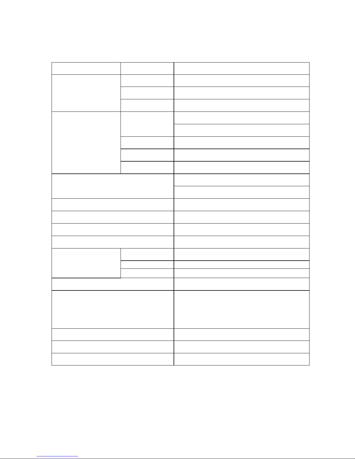
1.1 Product Features
Monitor Model AOC e2252VW
LCD Panel
Driving system TFT Color LCD
Active Display Area 476.64mm (W)×268.11mm(H) 546.86mm diagonal
Pixel Pitch 0.24825 mm×0.24825mm
Input
Video
R,G,B Analog Interface,75ohm,0.7V
DVI digital Interface
Separate Sync. H/V TTL
H-Frequency 30kHz—80kHz
V-Frequency 56Hz--75Hz
Input Connector
D-Sub 15pin
DVI 24pin
Display Colors 16.7M Colors
Dot Clock 108MHz
Max. Resolution 1600 x 900@60Hz
Plug & Play VESA DDC2B DDC/CI
Power Consumption
ON Mode <35W
Power Saving Mode <1W
Switch OFF
<0.5W
Power Source
90~264VAC,47~63Hz, 1.5A Max supply current
Environmental
Considerations
Operating Temp: 0° to 40°C
Storage Temp.: -20° to 60°C
Operating Humidity : 8% to 80%
Altitude:Operating 0~3,658m (0~12,000ft)
Non-Operating 0~12192m (0~40,000ft)
Dimensions(including stand)
496.5(W)x378.6(H)x186 (D)mm
Weight (N. W.): 3.5kg
Safety
FCC B CE mark CCC IEC950CB etc.
Page 5
Service Manual AOCe2252VW
5
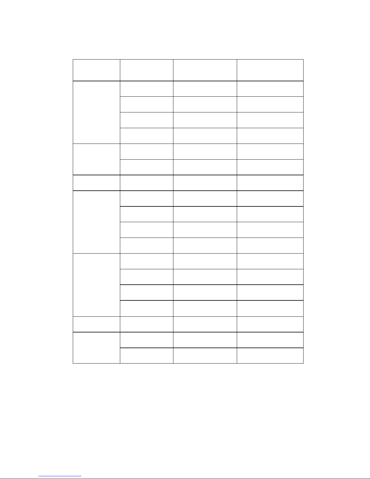
1.2 Factory preset modes
STANDARD RESOLUTION
HORIZONTAL
FREQUENCY
VERTICAL
FREQUENCY
VGA
640×480
31.469kHz 59.94Hz
640×480
35.00kHz 66.67Hz
640×480
37.861kHz 72.80Hz
640 × 480 37.50kHz 75.00Hz
DOS-mode
640 × 480 31.469kHz 70.087Hz
720 × 400 31.469kHz 70.087Hz
Mac-mode 832 ×624 49.725kHz 74.50Hz
SVGA
800 × 600 35.16kHz 56.25Hz
800 × 600 37.879kHz 60.317Hz
800 × 600 48.07kHz 72.188Hz
800 × 600 46.875kHz 75Hz
XGA
1024 × 768 48.363kHz 60Hz
1024 × 768 56.476kHz 70Hz
1024 × 768 60kHz 75Hz
1280 × 720 45kHz 60KHz
WXGA 1600 × 900 60.00kHz 60Hz
WSXGA
+
1920 x 1080@60Hz 67.5kHz 60.000Hz
1920 x 1080@60Hz 67.158kHz 59.963Hz
1.3 New Features
21.5”W Active matrix LCD panel,LED driver backlight;
Resolutions: 640 x 480 up to 1920 x 1080/60HZ
Dynamic Contrast Ratio(DCR) 20000000:1
Display Interface: VGA, DVI;EPA 5.0
Page 6
Service Manual AOCe2252VW
6
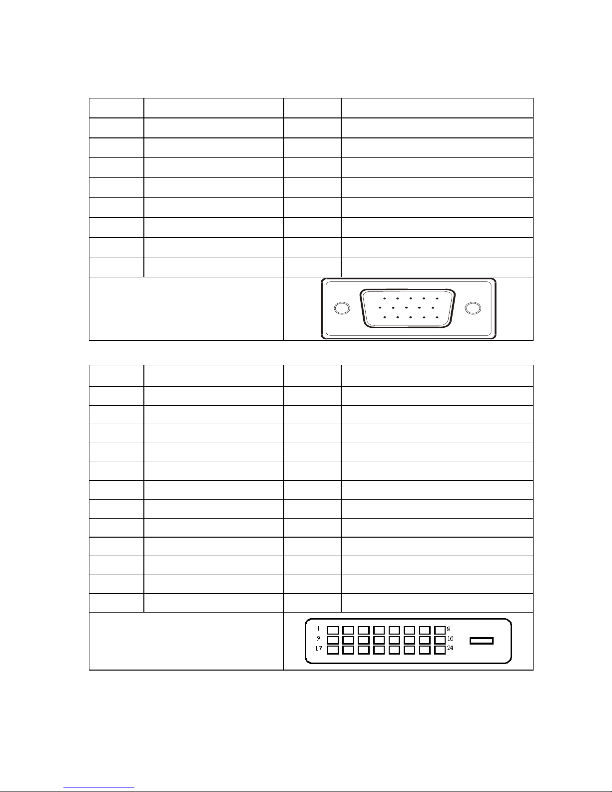
1.4. DVI+VGA Interface description
VGA 15pin Connector
Pin No. Description Pin No. Description
1. Red Input 9. +5VDC
2. Green Input 10. Logic GND
3. Blue Input 11. N/A
4. N/A 12. SDA- DDC-Serial Data
5. Connection detect 13. H Sync
6. Red GND 14. V Sync
7. Green GND 15. SCL- DDC-Serial Clock
8. Blue GND
VGA Connector layout
15
6
10
11 15
DVI Connector
Pin No. Description Pin No. Description
1. TMDS Data 2- 13. TMDS Data 3+
2. TMDS Data 2+ 14. +5V Power
3. TMDS Data 2/4 Shied 15. Ground (for +5V)
4. TMDS Data 4- 16. Hot Plug Detect
5. TMDS Data 4+ 17. TMDS Data 0+
6. DDC Clock 18. TMDS Data 0-
7. DDC Data 19. TMDS Data 0/5 Shield
8. N.C. 20. TMDS Data 5-
9. TMDS Data 1- 21. TMDS Data 5+
10. TMDS Data 1+ 22. TMDS Clock Shield
11. TMDS Data 1/3 Shield 23. TMDS Clock+
12. TMDS Data 3- 24. TMDS Clock-
DVI Connector layout
Page 7
Service Manual AOCe2252VW
7
2. Operation instruction
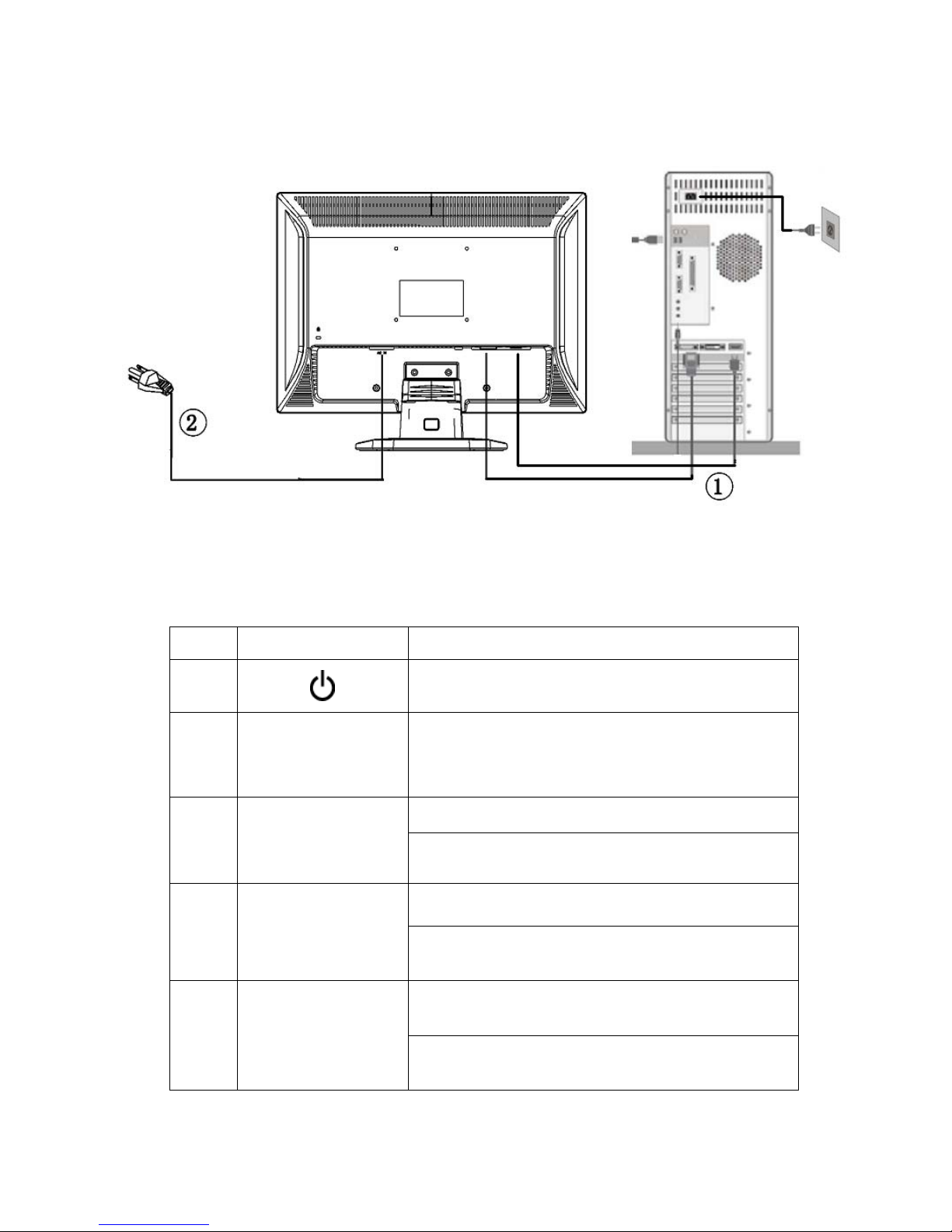
2.1 Connection
The power cord should be connected.
Connect the video cable from the video card of PC to the monitor.
Press the power button to turn on the monitor, the power indicator will light up.
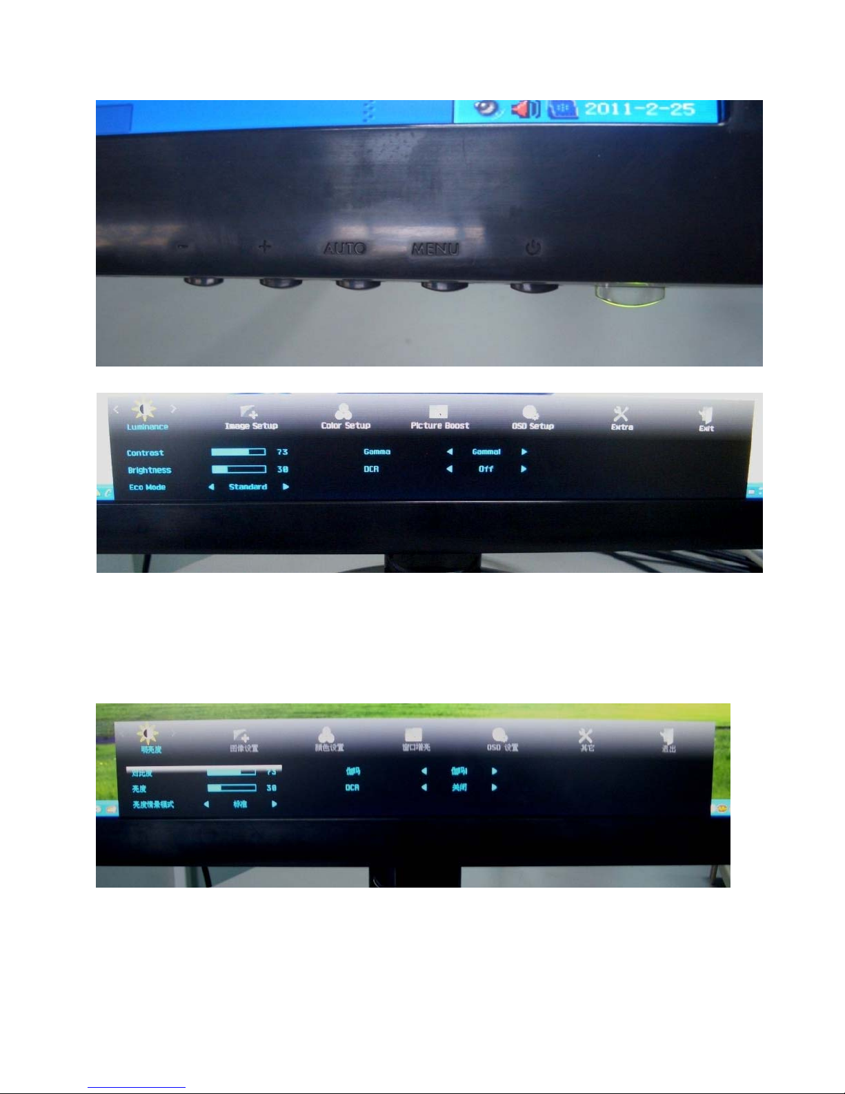
2.2 Control Buttons
Control Button Description
1
To turn ON/OFF the moniteor, and power indicator
(Green/Orange).
2
Menu / Enter
Active main menu while no OSD display,enter next level on
main menu or sub menu status, or enter last level on
adjustment bar. Select Exit icon then press Menu button to
return to superior menu.
3
Auto/Exit
Hotkey ,Input Source selection.
There is OSD, press Auto button to exit OSD.
4
+/4:3 or wide
/up
Hotkey, chang 4:3 or wide image ratio or do auto configure
OSD, increase current value of bar, or move to next item of
menu
5
-/Down
Hotkey, Switch display mode
OSD, it will decrease current value of bar, or it will move to
last item of menu.
Page 8
Service Manual AOCe2252VW
8
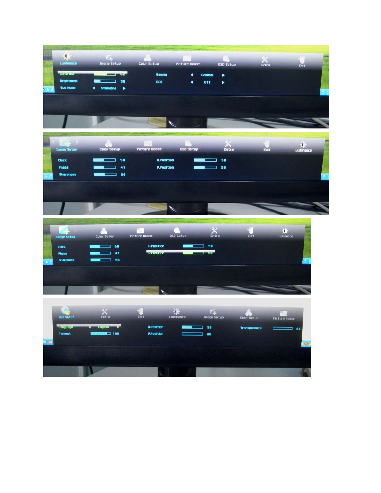
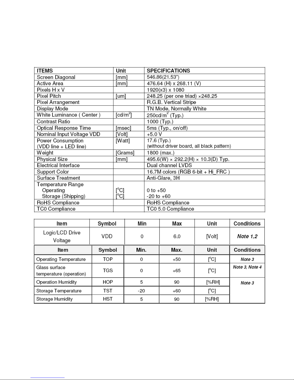
2.3 OSD User mode adjustment
a) OSD Menu adjustment steps:
1. Press MENU to activate OSD main menu, Touch
+/ - button may select other Menu item..
2. Press MENU button to select items of each main menu.Touch
+/ - to move and select.
3. Press MENU may select item you wish to enter. Touch
+/ - to adjust item you selected.
4. Press MENU button to enter,
5. Press AUTO to EXIT OSD
6. Repeat steps 2-5 to adjust an additional item,
Page 9
Service Manual AOCe2252VW
9
Page 10

Service Manual AOCe2252VW
10
Page 11

Service Manual AOCe2252VW
11
b) hotkey OSD Menu as shown below
AUTO
Source selection
+
Screen switching
_
Switch display mode
Page 12

Service Manual AOCe2252VW
12
2.4 OSD Locked
When press “
” to switched on the monitor, while holding press the” menu” button, the menu
will be locked.
Again, the OSD menu is non-locked.
Page 13
Service Manual AOCe2252VW
13
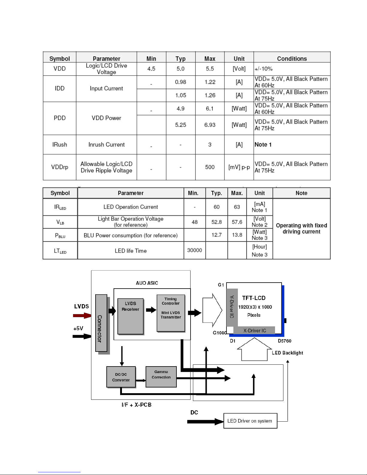
3. Panel Feature
This specification applies to the 21.5 inch-wide Color a-Si TFT-LCD Module M215HW01.The display supports the Full
HD - 1920(H) x 1080(V) screen format and 16.7M colors (RGB 6-bits + Hi-FRC data). All input signals are 2-channel
LVDS interface and this module doesn’t contain an driver board for backlight.
3.1 General Specifications
3.2 Electrical Absolute Ratings
Page 14
Service Manual AOCe2252VW
14
3.3 Electrical Characteristics
LED array ELECTRICAL CHARACTERISTICS
3.4 TFT LCD Module Block Diagram
Page 15
Service Manual AOCe2252VW
15
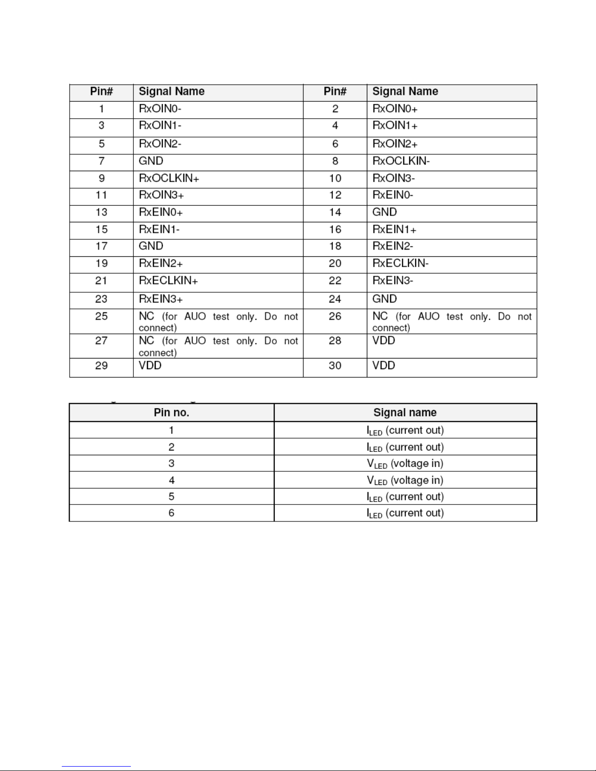
3.5 LCD module input terminal pin assignment
3.6 LED Interface
LED connector on Backlight Unit pin configuration CI1406M1HRB-NH
Page 16
Service Manual AOCe2252VW
16
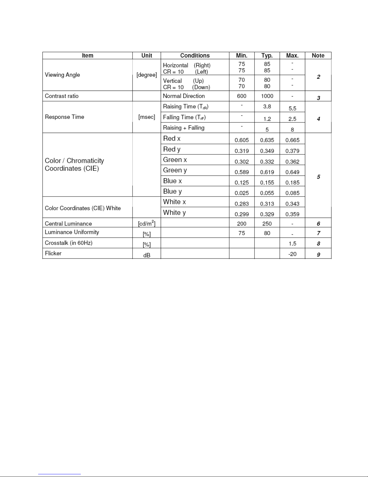
3.7 Optical Specifications
Page 17
Service Manual AOCe2252VW
17
4.Block Diagram
4.1 LCD Block Diagram
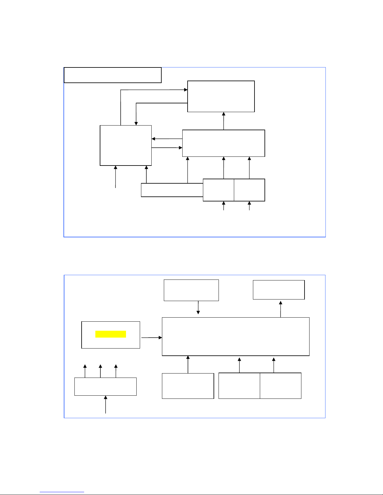
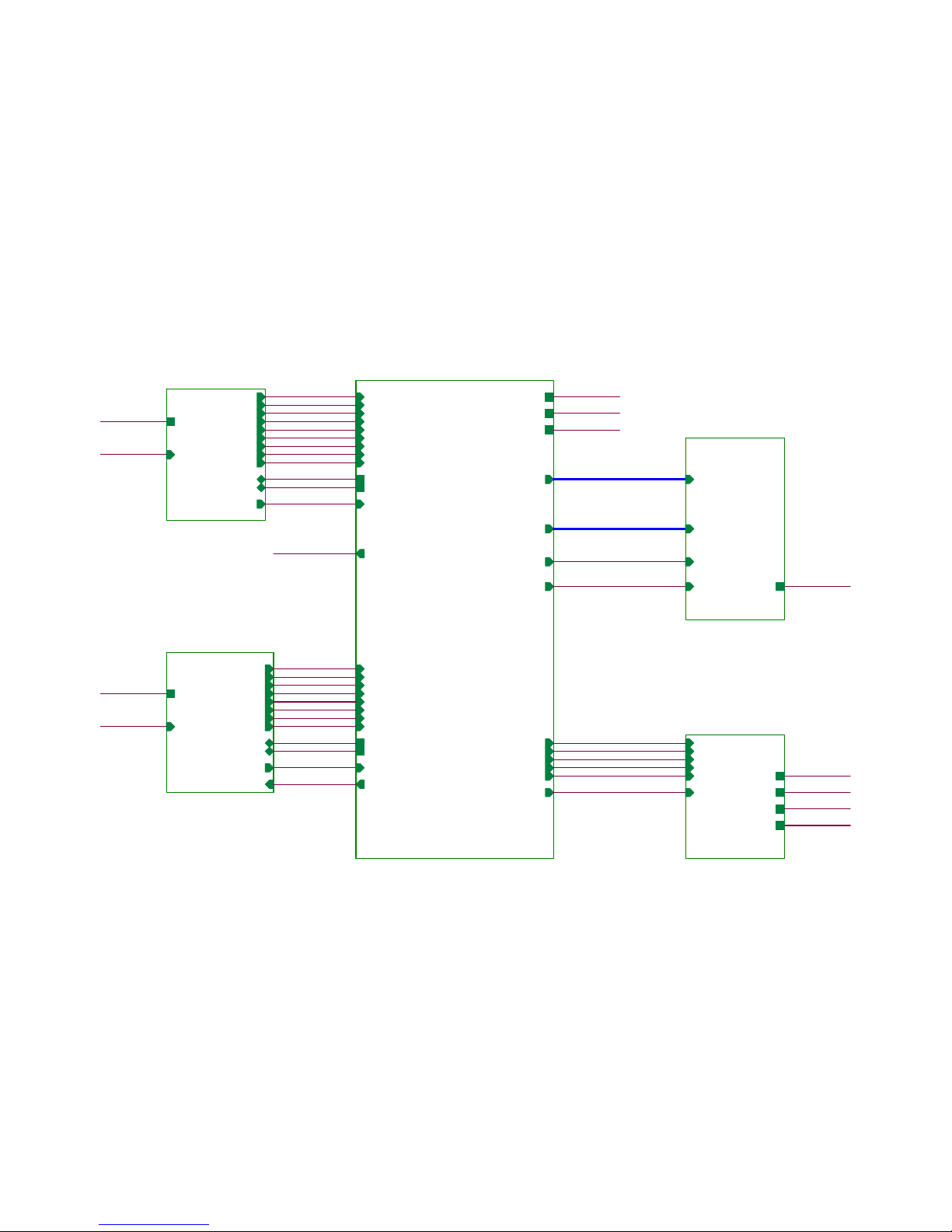
4.2 MainBoard Block Diagram
Crystal
14.318MHz
Panel Interface
(CN301/302)
MCU-Scarlar NT68660
(Include ADC, OSD, MCU)
(U401)
D-Sub
Connector
(CN101)
EEPROM
MX25L2026
(U402)
H sync
V sync
Key Board
Control
(CN401/402)
Voltage converter
5V
5V 3.3V 1.8V
DVI
Connector
(CN102)
Converter
AC-DC(5V/12V)
Power Board
Main Board
715G4502
Key board
PC- VGA
/DDC
LED-bar backlight
Panel
LVDS
AC supply
90V-264V
Monitor Block Diagram
PC- DVI
/DDC
Input signal
Page 18
Service Manual AOCe2252VW
18
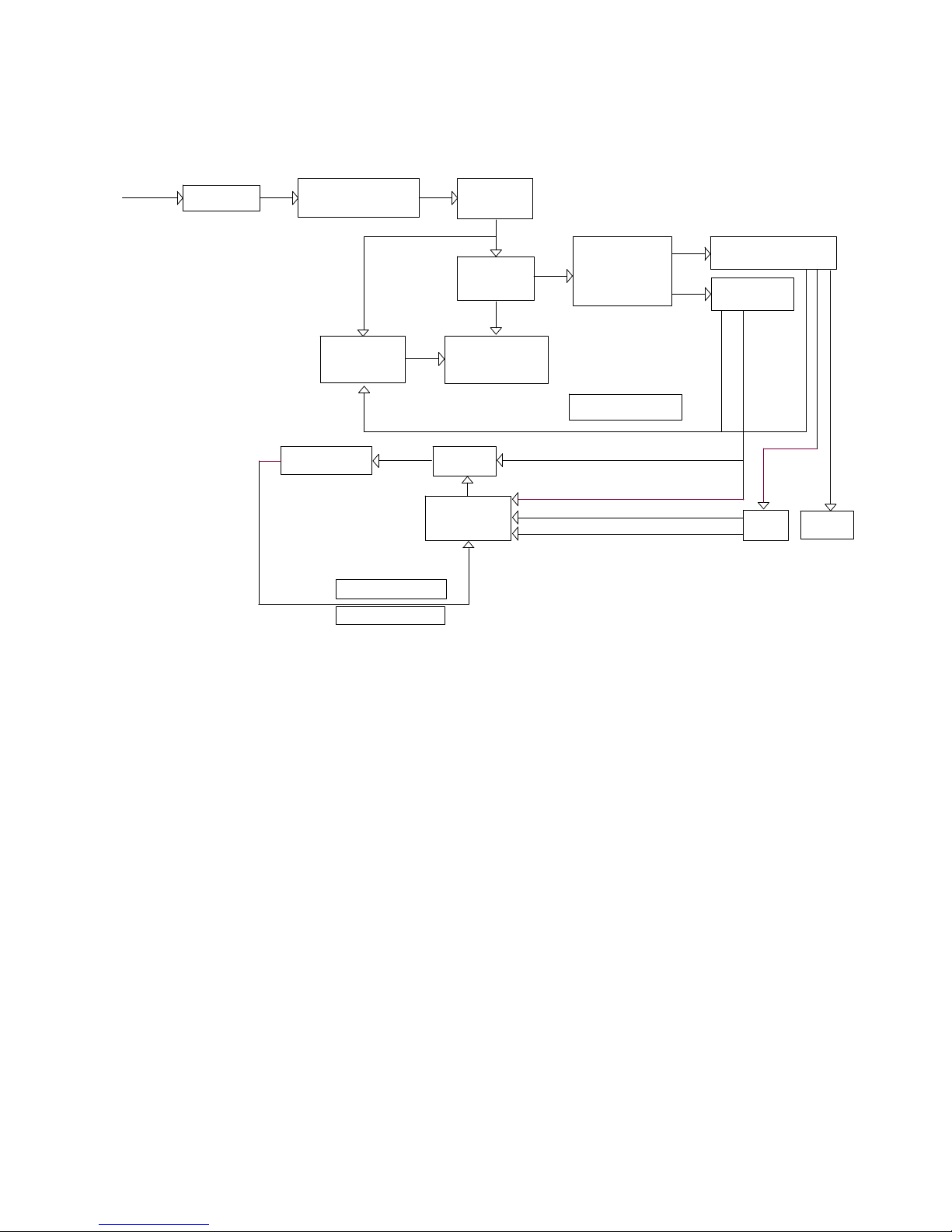
4.3 Power Board Block Diagram
Power MOS
MP3389
EMI Filter
16V Output
Dimming Signal
8A/700V
Protection Circuit
AC Input
Condenser
AUDIO
(2)10A/200V
Input Filter
Feedback Circuit
5V Output
Feedback Circuit
LD7750RGR
MMD 21.5" LIPS Block Diagram
Bridge Rectification
Rectifier Diode
BOOST
Flyback
LED Light bar
(1)10A/60V
CN902
Adapter IC
Transformer
2A 800V
ON/OFF Signal
Inverter IC
Page 19
Service Manual AOCe2252VW
19
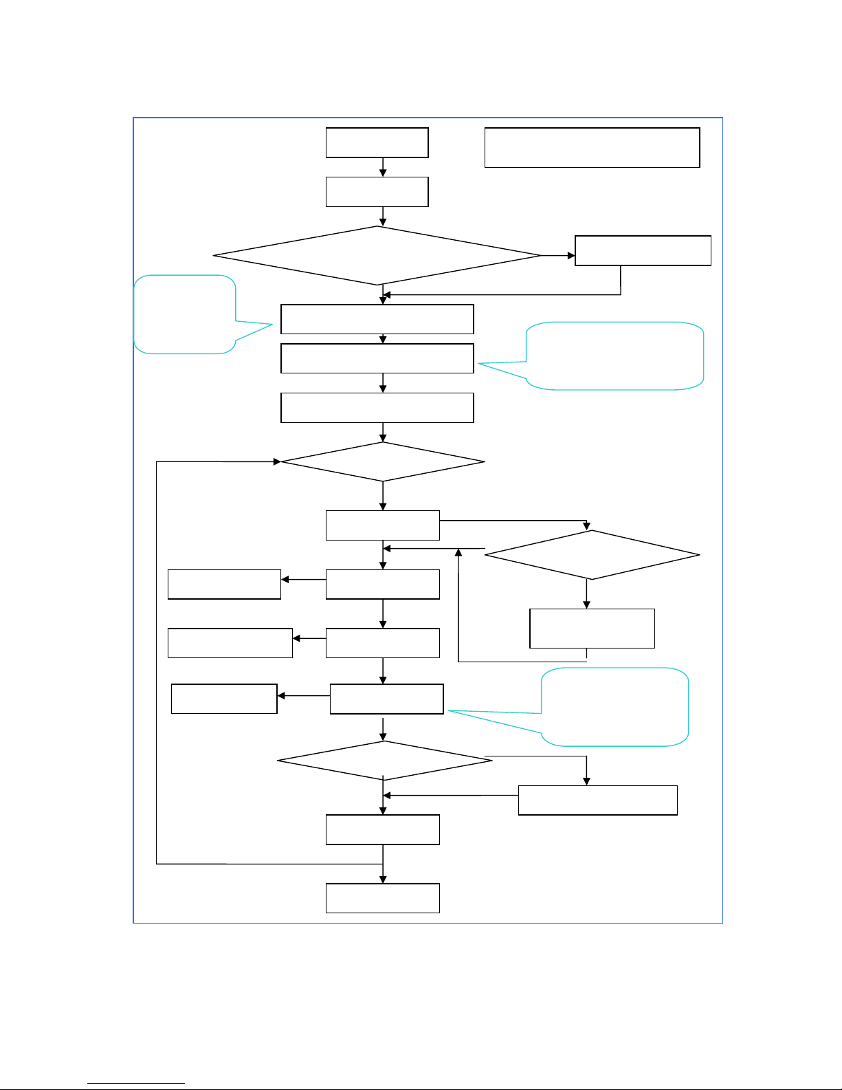
4.4 Software Flow Chart
Start
Initial_MCU
Check if DataBuffer Is blank
Check if Sum is chan
g
ed ?
To Write default values
Read parameter_from Buffer
PowerHandler
Init_GlobalVariables
Initial_MCU Device
while
InputTiming
ModeHandler
MenuHandler
DebugHandler
if standby mode?
Brightness
Contrast
Language
InputType
InputTimingStableCounter
OsdCounter
PowerDownCounter
LED turn-on
Show power on logo
if factory mode?
No signal message
UnsupportModeFlag
END
OSD Menu
Software Flow Chart
InputTiming
Phaes/Frequency
Image setup
Color
Enter factory mode OSD
Y
N
Y
Page 20
Service Manual AOCe2252VW
20
5. Circuit Schematic
5.1 Main Board 1-715G4502
03.DVI INPUT
03.DVI INPUT
RX0+
RX0-
RX1-
RX1+
RX2+
RX2-
RXC-
RXC+
DDCSCL2
DDC SDA2
DVI_C ABLE_DET
EDID _WP
+5V
DVI_HPD
Audio_EN
AVS0
on_BACKLIGH T
+5V
PS_EN
EDID _WP
VLCD
Adj_BACKLIGH T
Audio_DET
+5V
RX1+
04.SCALER
04.SCALER
Adj_BACKLIGH T
on_BACKLIGH T
Audio_EN
Audio_DET
PS_EN
Panel_ON
PB[0.. 9]
PA[0.. 9]
R0+
R0SOG_DET
G0+
G0B0+
B0AHS0
AVS0
DDCSCL1
DDCSDA1
EDID _WP
VGA_CABLE_DET
RXC+
RXC-
RX2-
RX2+
RX1+
RX1-
RX0-
RX0+
DDCSCL2
DDCSDA2
DVI_C ABLE_DET
DVI_HPD
VCC1.8
VCC3.3
+5V
P_SCL
P_SDA
VLCD
DDCSCL1
02.IN PUT
02.D-SU B INPUT
R0+
R0-
SOG_DET
G0+
G0-
B0+
B0-
+5V
AHS0
AVS0
DDCSCL1
DDCSDA1
EDID _WP
VGA_CABLE_DET
DVI_CABLE_DET
RX1-
R0-
EDID _WP
RXC-
Panel_ON
DDCSD A2
PB[0.. 9]
VCC3.3
PA[0.. 9]
DDCSCL2
DVI_HPD
+5V
G0+
VCC1.8
AHS0
+5V
R0+
SOG_DET
RX0-
EDID _WP
05.PANEL I NTERFACE
05.PANEL I NTERFACE
VLCD
PA[0.. 9]
PB[0.. 9]
P_SCL
P_SDA
VGA_CABLE_DET
G0-
RX0+
06.POWER
06.POWER
Adj_BACKLIGH T
on_BACKLIGH T
Audio_EN
Audio_DET
PS_EN
Panel_ON
+5V
VCC3.3
VCC1.8
VLCD
B0+
RX2+
DDCSDA1
RX2-
VCC1.8
VCC3.3
B0-
RXC+
Page 21

Service Manual AOCe2252VW
21
Input part---VGA/DDC
C112
NC/22pF 50V
C105 47N16V
VGA_5V
R112
75 OHM +-5% 1/16W
R116 22K 1/16W 5%
DET_VGA
C181
22P 50V
R121
100R 1/16W 5%
R103
0R05 1/16W
DDCSCL1
RIN0
DDCSDA15
R109
0R05 1/16W
B0+ 5
C101
220N16V
ESD_VGA
C109
5PF 50V
VGA_5V
B0+
GIN0-
VGA_5V
D101
BAV70
3
1
2
DDCSCL_A
VSIN0
CN101
D-SUB 15P
1
6
2
7
3
8
4
9
5
11
12
13
14
15
10
17 16
SOG_DET 5
VGA_CABLE_DET
R104
0R05 1/16W
DDCSDA1
C182
22P 50V
C111
NC/22pF 50V
DDCSDA1
C114
100N 16V
R0-
BIN0
+5V4,5,7
B0- 5
GIN0-
G0- 5
RIN0-
GIN0
C110
47N16V
DDCSDA_A
R105
100R 1/16W 5%
DDCSDA_A
AVS0 5
EDID_W P
C103
5PF 50V
RIN0-
HSIN0
DDCSCL_A
R108
100R 1/16W 5%
BIN0-
DET_VGA
C107
47N16V
R0+
R0- 5
ESD_VGA
C106
5PF 50V
AHS0 5
R124 100R 1/16W 5%
U101
FM24C02A
1
2
3
45
6
7
8
A0
A1
A2
GNDSDA
SCL
WP
VCC
R115 4K7 1/16W 5%
R111
100R 1/16W 5%
GIN0
BIN0
B0-
R125
2K2 1/16W 5%
U102
AZC399-04S
1
2
3 4
5
6
I/O1
GND
I/O2 I/O3
VDD
I/O4
R114 4K7 1/16W 5%
BIN0-
BIN0
C102
47N16V
R117
0R05 1/16W
GIN0
HSIN0
R142
470R 1/16W 5%
HSIN0 R123 100R 1/16W 5%
EDID_W P4,5
R120
75 OHM +-5% 1/16W
R101
100R 1/16W 5%
R0+ 5
DUAL 1.0
e2252Vw
B
37Friday , January 07, 2011
715G4502-M01-000-0040
<
称爹
>
D-SUB I/ O
G4502-M01-000-0040-1-110107
OEM MODEL Size
Rev
Date
Sheet
of
TPV MODEL
PCB NAME
称爹
T P V ( Top Victory Electronics Co . , Ltd. )
Key Component
絬 隔 瓜 絪 腹
R110
0R05 1/16W
C120
1NF 50V
ESD_VGA
C108
47N16V
G0-
R107
75 OHM +-5% 1/16W
G0+ 5
R122 0R05 1/10W
VSIN0
VSIN0
ZD101
RLZ5.6B
DDCSCL15
R113
100R 1/16W 5%
U103
AZC399-04S
1
2
3 4
5
6
I/O1
GND
I/O2 I/O3
VDD
I/O4
RIN0
DDCSCL1
+5V
R106
100R 1/16W 5%
R102 100R 1/16W 5%
G0+
VGA_CABLE_DET 5
RIN0
R126
2K2 1/16W 5%
C104
47N16V
R118
0R05 1/16W
R119
100R 1/16W 5%
C113
100N 16V
Page 22

Service Manual AOCe2252VW
22
DVI input
C115
100N 16V
DVI_CABLE_D ET 5
R140 10R 1/16W 5%
ESD_DVI
D102
BAV70
3
1
2
R133 22K 1/16W 5%
RXC- 5
R131 4K7 1/16W 5%
RX2- 5
EDID_W P
RX1+ 5
DVI5V
DDCSCL2 5
DAT2+
RX1- 5
RXC+ 5
SDA_DVI
ZD102
RLZ5.6B
Q101NC
ESD_DVI
ESD_DVI
SCL_DVI
R136 10R 1/16W 5%
RX0- 5
R127
100R 1/16W 5%
DAT1-
R138 10R 1/16W 5%
U106
AZC399-04S
1
2
3 4
5
6
I/O1
GND
I/O2 I/O3
VDD
I/O4
RX2+ 5
U105
FM24C02A
1
2
3
45
6
7
8
A0
A1
A2
GNDSDA
SCL
WP
VCC
DDCSDA2 5
DAT0-
DET_DVI
R139 10R 1/16W 5%
R137 10R 1/16W 5%
HPD
DVI5V
DCLK+
DVI_HPD 5
C117
100N 16V
ESD_DVI
C118
100N 16V
DVI5V
CN102
JACK
1
2
3
4
5
6
7
8
9
10
11
12
13
14
15
16
17
18
19
20
21
22
23
24
26
25
DAT2-
DAT2+
2/4shield
DAT4-
DAT4+
DDC SCL
DDC SDA
VSYNC
DAT1-
DAT1+
1/3shield
DAT3-
DAT3+
+5V
SYNC GND
HPD
DAT0-
DAT0+
0/5shield
DAT5-
DAT5+
clk shield
clk+
clk-
GND
GND
DAT1+
DAT0+
+5V3,5,7
ESD_DVI
R141 10R 1/16W 5%
U107
AZC399-04S
1
2
3 4
5
6
I/O1
GND
I/O2 I/O3
VDD
I/O4
U104
AZC399-04S
1
2
3 4
5
6
I/O1
GND
I/O2 I/O3
VDD
I/O4
R132 4K7 1/16W 5%
DUAL 1.0
OTS
B
47Friday , January 07, 2011
715G4502-M01-000-0040
<
称爹
>
DVI
G4502-M01-000-0040-1-110107
OEM MOD EL Size
Rev
Date
Sheet
of
TPV MODEL
PCB NAME
称爹
T P V ( Top Victory Electronics Co . , Ltd. )
Key Component
絬 隔 瓜 絪 腹
EDID_WP 3,5
R135 10R 1/16W 5%
R134 10R 1/16W 5%
C116
220N16V
+5V
DAT2-
R128 100R 1/16W 5%
RX0+ 5
DCLK-
ESD_DVI
R129 100R 1/16W 5%
C119
100N 16V
R130 1K 1/16W 5%
Page 23

Service Manual AOCe2252VW
23
Power part---5V/3.3V/1.8V
Q703
NC/2N3904S-R TK/PS
+
C710
100uF16V
Panel_ON5
Audio_EN 5
U701 AZ1117H-3.3TRG1
3
1
2
4
INPUT
ADJ/GN D
OUTPUT
4
C712
100N 16V
Adj_BACKLIGHT 5
+5V
CN701
CONN
1
2
3
4
5
6
7
8
9
R711 NC/0R05 1/ 16W
R701
22K 1/16W 5%
C706
100N 16V
+5V3,4,5
FB701
0 OHM +-5% 1/8W
ON/OFF
Q702
NC/2N3904S-RTK/PS
DIM
C713
100N 16V
R724
NC
C704
100N 16V
R721
4K7 1/16W 5%
R708
NC/10K 1/16W 5%
U704
3 2
1
VIN VOUT
GND
VCC1.8 5
+
C705
100uF16V
R716
NC/10K 1/16W 5%
R712 NC/100R 1/16W 5%
R703 100R 1/16W 5%
TO-252
+5V
R718
NC
R707
4.7 OHM +-5% 2WS
Audio_DET 5
+5V
R717
NC
Audio_DET2
R725
NC
R719
22K 1/16W 5%
ON/OFF
R714
10K 1/16W 5%
R709
NC/22K 1/16W 5%
+5V 3,4, 5
R710
NC/100K 1/16W 5%
R720
NC
Audio_EN1
With audio Add R711 = 0 ohm, R712 / R798 = 100 ohm
C718
100N 16V
Q707
NC/2N3904S-R TK/PS
R706
NC/10K 1/16W 5%
R704
10K 1/16W 5%
VCC3.3
VLCD
VCC3.3
C717
NC/100NF 25V
Q705
AO3401A
DIM
Audio_DET1
VCC3.3
R713 NC
C715
220N16V
Q704
NC/AO4449 -7A/-30V
123
4
876
5
SSS
G
DDD
D
Q701
LMBT3904LT1G
+5V
CN702
NC/CONN
1
2
3
4
5
6
R722
NC/10K 1/16W 5%
VLCD 6
R798
NC/100R 1/16W 5%
VCC3.3
R723
NC/4K7 1/16W 5%
R727
NC/0 OHM +-5% 1/8W
R726
0 OHM +-5% 1/8W
PS_EN 5
+5V
R715
100K 1/16W 5%
C701
100N 16V
C714
NC/100NF 25V
R799
10K 1/16W 5%
VCC1.8
DUAL 1.0
e2252Vw
B
77Friday, January 07, 2011
715G4502-M01-000-0040
<
称爹
>
POWER
G4502-M01-000-0040-1-110107
<Variant Name>
OEM MOD EL Size
Rev
Date
Sheet
of
TPV MOD EL
PCB NAME
称爹
T P V ( Top Victory Electronics Co . , Ltd. )
Key Component
絬 隔 瓜 絪 腹
VCC3.3 5
C707
NC/100N 16V
U703
AZ1117H-1.8-E1
3 2
1
4
VI VO
GND
4
C708
NC
Q706
LMBT3904LT1G
+
C716
100uF16V
C709
NC/100NF 25V
R702
4K7 1/16W 5%
+
C702
100uF16V
TO252
C703
100N 16V
VCC3.3
U401=NT68660FG U703 U704 R707 C710 C712 C713 is NC
U702
NC/G1117-33T43UF
123
ADJ(GND)
VOUT(TAB)
VIN
+5V
on_BACKLIGHT 5
VCC3.3
Page 24

Service Manual AOCe2252VW
24
AVCC
B0+
SPI_SI
MSCL
KEY2
VCC3.3
C422
100N 16V
P35*
LVACKM
LED_1
PS_EN 7
U401 NT68660FG FB401 and FB402 is
NC==>3.3V use TO252 type
U401 NT68660UFG FB402 is NC==>3.3V
and 1.8V LDO use SOT-223 type
DVI_HPD
RXC-
LVA3M
PA4*
CVDD
AVS0
P/SDA
LVBCKM
R447 NC/ 100R 1/16W 5%
VGA_CABLE_DET3
MSCL
RX0-4
R432
1MOHM 1/16W +/-5%
Q402
LMBT3906LT1G
FB404
300OHM
DDCSDA13
on_BACKLIGHT 7
P34*
LVB3M
DDCSDA2
Audio_DET 7
ADC0
LVB1P
R418
470OHM +-5% 1/10W
PB[0..9]
KEY1
TP4
TP-R- 0.7 5
R0-3
LPD_IN1*
LVB1M
LVB2P
PB5
LED_G
LED_2
FB401
300OHM
R445 NC/ 100R 1/16W 5%
R457
NC
PA5*
RX1-
PB6
Q401
LMBT3906LT1G
R402 NC/2K2 1/ 16W 5%
PA[0..9]6
EDID_WP
R442
NC/4K7 1/16W 5%
PA3
C402
100N 16V
PA0*
LVACKM
LVA1M
DVI_CABLE_DET
R415
100K 1/16W 5%
R414
NC/0R05 1/16W
LVB3P
PB4
R451
NC
RX0+4
TOUCH_POWER
Audio_DET
C409100N 16V
D402
NC/RLZ 5.6B
R454
22K 1/16W 5%
P_SDA
PE0*
PA6
DDCSCL2
PC5
PA8
LVB2M
POWER
PA4
D404
NC/RLZ5.6B
EDID_WP
P34*
KEY1
RESETB
R431 100R 1/16W 5%
C428
22P 50V
P/SCL
ADC2
PA1
CABLE_DET
PC6
+5V
R485 NC
R436
NC/22K 1/16W 5%
AHS03
PC4
PB8
5V_DET
LVA1P
CN405
NC/7PIN
1
2
3
4
5
6
7
LVA3M
P35*
RX2+
SPI_CK
R422
100K 1/16W 5%
LVA2M
R444
10K 1/16W 5%
R486 NC
RX1+4
VCC3.3 7
ADC3
VCC3.3
LVA1P
EE_WP
PA7
VGA_CABLE_DET
PC4
MSCL
R408
470R 1/16W 1%
CVDD
PB3
R456
NC/4K7 1/16W 5%
DVI_HPD 4
VCC1.8
PA9 LVA0M
FB405
300OHM
G0-
PB7
LVACKP
ADC1
R413
2K2 1/16W 5%
PA9
PA5
R440
NC/0R05 1/16W
R452
NC
LVA1M
R453
0R05 1/16W
C418
100N 16V
PC5
VCC3.3
PA0
R438
NC/10K 1/16W 5%
LED_G
LVB0M
PA2
C453
NC
R483
NC/4K7 1/16W 5%
R407 0R05 1/16W
PA1
DDCSCL1
R405
3K9 +/-5% 1/16W
U402
Pm25LD020C-SCE
1
2
3
4
8
7
6
5
CE#
SO
WP#
GND
VDD
HOLD#
SCK
SI
CN402
CONN
1
2
3
4
5
6
DDCSDA24
PA3*
LED_A
LVBCKP
KEY2
C430
NC/220N 10V
RXC-4
LVACKP
R0-
R417
330OHM 1/10W
FB406
NC/120 OHM
1 2
PB4
PC1*
INTB(PWM)
R416
220K 1/16W 5%
DDCSCL13
PC0*
+5V
5V_DET_INT
SOG_DET3
SPI_SI
RX0-
CABLE_DET
LED_A
DVDD
VCC3.3
PA[0..9]
PA8
R455
NC/4K7 1/16W 5%
FB402
NC/300OHM
LVB0M
R419
390K
C437
NC
R406 0R05 1/16W
R0+
C421
4.7UF 10V
C0805
R427
10K 1/16W 5%
AVS03
AVCC
PB6
LVB1M
PB9
PA5
RESETB
ADC1
CN404
NC/CONN
1
2
3
4
5
6
7
CN403
NC/6PIN
1
2
3
4
5
6
RX1-4
VCC3.3
R411
2K2 1/16W 5%
FB408
300OHM
DVDD
P/SCL
C414
1UF 10V
C0402
RXC+4
C401
4.7UF 10V
C0805
C427
100N 16V
SPI_SO
D401
NC/RLZ 5.6B
AVCC
DDCSDA1
CN411
NC/CONN
1
2
3
4
5
PB3
R434 100R 1/16W 5%
CN401
NC/8PIN
2
4
6
8
1
3
5
7
PA7*
WP
LVA0M
LVB2M
OSC_VDD
PB7
LED_1
C403
100N 16V
R0+3
PB2
R439
100R 1/16W 5%
P_SCL
LVA3P
C425 100N 16V
C423
4.7UF 10V
C0805
PC6
R410
0R05 1/16W
LED_A
5V_DET
R424 1K 1/16W 5%
X401
12MHZ
1 2
SPI_CK
C408100N 16V
C417
100N 16V
C415
100N 16V
R403 NC/2K2 1/ 16W 5%
PWMC*
B0-
R404
3K9 +/-5% 1/16W
C412100N 16V
PA2
INTB(PWM)
C416
4.7UF 10V
C0805
R443
NC/22K 1/16W 5%
PA7
MSDA
SPI_SO
MSDA
R488 1K 1/16W 5%
R487 1K 1/16W 5%
R412
NC/0R05 1/16 W
Adj_BACKLIGHT 7
LVA0P
C419
100N 16V
ADC3
U401
NT68660UFG/A
30
62
1
2
11
3
4
5
6
24
7
8
10
14
15
16
17
18
19
20
21
13
12
44
43
83
98
97
25
26
37
92
28
27
31
32
22
38
90
45
46
47
48
49
50
51
74
75
72
71
70
69
68
67
66
65
64
63
9
61
60
59
58
57
56
55
54
53
52
34
84
33
93
94
100
99
96
76
23
39
78
77
85
86
88
87
89
91
40
80
81
41
35
36
73
29
82
79
42
95
RSTB
DGND
RX2+
RX2-
TVCC
RX1+
RX1RX0+
RX0-
DGND
RXC+
RXC-
REXT
AGND
BIN1+
BIN1-
SOG1I
GIN1+
GIN1-
RIN1+
RIN1-
ADC_1V8
ADC_3V3
P31*/TXD*
P30*/RXD*
PB2/ADC2/INTE0
PB7*/DVI_SDA* /TXD*
PB6*/DVI_SCL* /RXD*
HSYNCI1
VSYNCI1
DGND
OSC_VDD
PB5*/VGA_SDA*/ TXD*
PB4*/VGA_SCL*/ RXD*
P35*
P34*
DVDD
DVDD
PC6/INTE2
NC
NC
NC
NC
NC
NC
NC
NC
NC
T0M
T0P
T1M
T1P
T2M
T2P
TCLK1M
TCLK1P
T3M
T3P
TGND
T4M
T4P
T5M
T5P
T6M
T6P
TCLK2M
TCLK2P
T7M
T7P
PA1*/PWMD*/D BC*
PA2*/PWMD*/D BC*
PA0*/PWMC*
OSCO
OSCI
PC5
PC4
PC1*/LPD_OU T*
PC0*/PWMA*/D BC*
DVDD
CVDD_1V8
PE1*/LPD_IN 1*/INT_VSO*
DGND
PA3*
SPI_CLK
SPI_SI
SPI_SO
SPI_CE
PC7
PA4*/INTE3*/ INT_HSO*
PA7*
PA6*/PWMC*
PA5*/PWMB*
PB0/ADC0
PB1/ADC1
DVDD
PE0*/PWMA*/LPD _IN0*
PB3/ADC3/INTE1
PE3*/PWMB*
PE2*/PWMA*/D BC*
OSC_GND
LVA0P
TP3
TP-R- 0.7 5
LVB0P
PB2
R437
NC/22K 1/16W 5%
C426
22P 50V
G0+3
PB5
PB9
PA6
LVB2P
WP
R425
10K 1/16W 5%
R401
3K9 +/-5% 1/16W
PB[0..9]6
R441
NC/4K7 1/16W 5%
RX2-4
DUAL 1.0
e2252Vw
C
57Friday, January 07, 2011
715G4502-M0E-000-0040
<
称爹
>
SCALER
G4502-M01-000-0040-1-110107
OEM MODEL Size
Rev
Date
Sheet
of
TPV MODEL
PCB NAME
称爹
T P V ( Top Victory Electronics Co . , Ltd. )
Key Component
絬 隔 瓜 絪 腹
MSDA
VCC1.8 7
PB1
P/SDA
C429
220N16V
ADC_VAA33
VCC3.3
LVA2P
DVI_CABLE_DET4
EE_WP
Panel_ON 7
ADC_VAA
LVBCKP
LVA3P
PB0
PA5*
+5V
LVA2M
Audio_EN 7
LVBCKM
LED_2
R409
0R05 1/16W
G0-3
PA3
LVB0P
Audio_EN
C404
4.7UF 10V
C0805
PWMB*
ADC2
SPI_CE
U403
NC/M24C16
1
2
3
45
6
7
8
A0
A1
A2
GNDSDA
SCL
WP
VCC
B0+3
VCC3.3
RX0+
AHS0
LVB3M
C411100N 16V
C420
NC
PA0
R429
10K 1/16W 5%
VCC3.3
R446
NC/0R05 1/16W
PA4*
VCC3.3
C410100N 16V
C405
100N 16V
SOG_DET
R423
220K 1/16W 5%
TXD*
+5V
D403
NC/RLZ 5.6B
PA3*
RX1+
PB1
PA4 LVA2P
C424
100N 16V
RXC+
DDCSCL24
VCC3.3
R484
NC/4K7 1/16W 5%
B0-3
PA1*
CN410
NC/CONN
1
2
3
4
5
6
PB8
SPI_CE
LVB1P
G0+
+5V 3,4,7
RXD*
ADC_VAA33
DVDD
PB0
PE2*
LPD_IN1*
ADC_VAA
+5V
POWER
C413
4.7UF 10V
C0805
OSC_VDD
PA0*
VCC3.3
RX2-
LVB3P
FB407
120OHM
1 2
RX2+4
MCU-Scarlar NT68660
Page 25

Service Manual AOCe2252VW
25
Output---LVDS connector
LVA0P
RXO1-
LVB3M
RXE2+
PA3
RXOC+
P_SCL
RXE1+
PA9
LVB1M
LVACKM
RXE3+
LVBCKP
PA0
LVA1P
FB409
120 OHM
1 2
PA6
P_SDA
RXOC-
LVACKP
RXE0+
LVB1P
RXEC-
RXE2-
PB[0.. 9]
RXO1-
LVBCKP
LVB2M
LVBCKM
LVA0P
RXO1+
LVA3M
RXOC+
PA5
PA1
RXEC+
LVB3M
RXE3+
LVA3P
VLCD 7
LVBCKM
LVB1P
RXEC-
RXE0-
RXE1+
PB[0.. 9]5
RXO3+
RXE1-
P_SCL
RXEC+
PA2
LVB1M
RXE2-
PB3
LVA2P
RXOC+
RXEC+
PA8
LVA1M
LVA3M
C436
NC
RXE3-
RXOC-
LVB0P
RXO2+
PA[0.. 9]
PB0
RXO0-
LVA1M
P_SDA
RXO3+
PB6
LVB3P
RXO3-
RXE1-
LVB2P
RXO2-
LVB2M
LVA0M
R448300 OHM 1/ 4W
LVACKP
RXO1+
LVB2P
LVA2M
RXO0+
LVA3P
LVA2M
+
C433
100uF16V
RXOC-
PB8
LVB3P
RXE2+
CN409
NC/CONN
2
4
6
8
10
12
14
16
18
20
22
24
26
28
30
1
3
5
7
9
11
13
15
17
19
21
23
25
27
29
P_SDA
RXO2-
PA7
PB4
PB5
PA4
C434
100N 16V
LVA0M
PA[0.. 9]5
PB9
PB7
RXEC-
R449300 OHM 1/ 4W
LVB0P
LVACKM
LVA2P
LVB0M
RXO0+
P_SCL
LVB0M
RXE3-
CN408
CONN
1
2
3
4
5
6
7
8
9
10
11
12
13
14
15
16
17
18
19
20
21
22
23
24
25
26
27
28
29
30
DUAL 1.0
e2252Vw
A
67Friday , January 07, 2011
715G4502-M01-000-0040
<
称爹
>
LVDS PANEL I /O
G4502-M01-000-0040-1-110107
OEM MO DEL Size
Rev
Date
Sheet
of
TPV MODEL
PCB NAME
称爹
T P V ( Top Victory Electronics Co . , Ltd. )
Key Component
絬 隔 瓜 絪 腹
VLCD
RXO2+
RXO3-
PB1
RXE0+
C435
NC
RXE0-
PB2 RXO0-
LVA1P
Page 26

Service Manual AOCe2252VW
26
5.2 Power Board 715G4750-P0C
--adapter 16V/5V
R901
47 OHM 1/4W
+
C911
470uF 16V
GND2
GND
1
2
R911
22 OHM 1/4W
L903
Coil
R932
680R
C900
3300pF 250V
R917
1.5M 1/4W
C926
100N 50V
R924
10 OHM 1/4W
D903
SRF1060
1
2
3
Q903
KTD1028
ENA
FB901
BEAD
1 2
R938
NC
R935
680R
FB902
BEAD
1 2
R921
4K7 +-5% 1/8W
R930
NC
R934
1K 1/8W
+
C908
330uF 35V
R906
200K 1/4W
R915
1K 1/8W 1%
R903
200K 1/4W
C931
470pF/1KV
Q901
SMK0870FJ
R908
6.8K 1/4W
R931
100KOHM +-5% 1/8W
C912
100N 50V
R923
10K 1/8W 1%
CN901
SOCKET
1 2
3
R910
0R05
C923
0.1uF 50V
+
C910
680uF 10V
T901
POWER X'FMR
1
2
3
5
4
6
8
9
10
+
C902
47uF M 450V
C934
1N 50V
R907
200K 1/4W
+5V
CN902
Wire Harness
1
2
3
4
5
6
7
C915
NC
C922
1N 50V
C906
1500PF2KV
IC901
LD7750RGR
1
2
3
4 5
6
8
OTP
COMP
CS
GNDOUT
VCC
HV
R929
NC
F902
FUSE
C925
2N2 500V
+5V
C929
100N 50V
CN802
NC
1
2
CN903
PHONE JAC K
1
2
3
5
4
C913
2N2 500V
C917
100N 50V
D902
PS1010R
+16V
R913
47 OHM 1/4W
R940
0 OHM +-5% 1/8W
+
C916
47UF 35V
HS2
HEAT SINK(D901)
1
2
C920
680PF 250V
C905
0.22UF275V
F901
FUSE
R904
200K 1/4W
D904
1N4148-B4006
R905
6.8K 1/4W
R918
1.5M 1/4W
HS3
HEAT SINK(D903 )
1
2
IC903
AS431AZTR-E1
056G 158 10 T
C901
2N2 500V
Rin
+
C903
47uF M 450V
R937 NC
DIM
Lin
16V/1.5A
R933
510OHM +-5% 1/8W
L902
Coil
R912
10K 1/4W
HS1
HEAT SINK(Q901)
1
2
R919
0.43 OHM +-5% 2W S
R902 47 OHM 1/4W
R927
9K1 1/8W 1%
+
C927
330uF 35V
IC902
PC123X2YFZOF
056G 139 3A
12
43
5V/2.5A
t
NR901
NTCR
1 2
PLPCAB521MAAW A
A3
22Wednesday , Nov ember 24, 2010
G4750-P0B-000-0010
ODM MOD EL
02.POWER
G4750-P0B-000-0010-1-101105
227E3LOEM MODEL Size
Rev
Date
Sheet
of
TPV MODEL
PCB NAME
称爹
T P V ( Top Victory Electronics Co . , Ltd. )
Key Component
絬 隔 瓜 絪 腹
ENA
L901
30MH
124
3
R914
47 OHM 1/4W
R909
6.8K 1/4W
R928
NC
-
+
BD901
D2SB80
2
1
3
4
GND1
GND
1
2
CN904
CONN
1
2
3
+
C907
330uF 35V
+16V
D901
SFF1004G
1
2
3
C921
680PF 250V
R916
1.5M 1/4W
C919
10N 50V
DIM
C924
2N2 500V
D905
PS1010R
R926
2K 1/8W
R939
0 OHM +-5% 1/8W
R920
220 OHM
CN801
NC
1
2
3
4
5
ZD902
TZX22B
1 2
Page 27

Service Manual AOCe2252VW
27
5.3 Converter Board -715G3977-P0C
R838
0R05 1/10W
LNPC9B611GAA2
A
Custom
22Monday, F ebruary 14, 2011
715G3977-P0C-000-0040
ODM MO DEL
01.CONVERTER
G3977-P0C-000-0040-1-100 111
OEM MO DEL Size
Rev
Date
Sheet
of
TPV MODEL
PCB NAME
称爹
T P V ( Top Victory Electronics Co . , Ltd. )
Key Component
絬 隔 瓜 絪 腹
R802
220K OHM +-1% 1/10W
+14.5V
+14.5 V
R837
0R05 1/10W
Q805
2N7002 SOT-23
R809
5.1KOHM +-1% 1/10W
+
C809
33UF 100V
C806
100pF 50V
R805
300KOHM 1/10W
Gate
R806
1K 1/10W
+
C807
33UF 100V
ON/OFF
DR
OVP
DR
+14.5V
R831
1 OHM +-5% 1/8W
U801
MP3389EF
1
2
3
4
5
6
7
8
9
10
11
12
13
14 15
16
17
18
19
20
21
22
23
24
25
26
27
28
29
NC
VIN
VCC
COMP
EN
DBRT
GND
OSC
ISET
BOSC
LED12
LED11
LED10
LED9 LED8
LED7
LED6
LED5
LED4
LED3
LED2
LED1
OVP
ISENSE
PGND
GATE
VFAULT
NC
E-Pad
R829 1 OHM +-5% 1/8W
R803
24KOHM 1/10W
R816
0.3 OHM +-5% 1/4W
Gate
CN802
CONN
1
2
3
4
R820
10ohm +/-1% 1/ 8W
CN801
CONN
1
2
3
4
5
6
7
OVP
+
C811
33uF 100V
R819
20K 1/10W
R830
1 OHM +-5% 1/8W
DIM
Q804
2N7002 SOT-23
CN804
CONN
1
2
3
4
5
6
7 8
Q803
MMBT390 6
R832
1 OHM +-5% 1/8W
Q801
AOD4126
R821
22R 1/8W 1%
R810
20K 1/10W
L801
22uH
ON/OFF
D801
SK310B
1 2
R804
100K 1/10W
R801
10 OHM 1% 1/4W
R824
2KOHM +-1% 1/4W
+
C810
33uF 100V
R826 NC
R811
3K9 1/10W
C804
470N 50V
DIM
R836
0R05 1/10W
R822
10K 1/10W
C803
470N 50V
R835
0R05 1/10W
C808
NC
Q806
NC(P8008H V)
123
4
876
5
S1G1S2
G2
D1D1D2
D2
R825
2KOHM +-1% 1/4W
R828
1 OHM +-5% 1/8W
Q802
MMBT3904
R812
0.3 OHM +-5% 1/4W
C801
470N 50V
R823
0R05OHM1/8W
CN803
CONN
1
2
3
4
5 6
R808
1K 1/10W
R818
0R05 1/4W
R807
20K 1/10W
C802
68NF 50V
R834
0R05 1/10W
C805
220P 100V
R813
0R05 4A 1/4W
DR
R827
1 OHM +-5% 1/8W
R833
0R05 1/10W
Page 28

Service Manual AOCe2252VW
28
5.4 Key Board 715G4851k
SW003
SW
(Power)
0.673V
AUTO
e2252Vw C
N/A
B
22Wednesday , February 16, 2011
715G4851-K0C-000-0010
<
称爹
>
2.0.k ey
715G4851-K0C-000-0010
OEM MODEL Size
Rev
Date
Sheet
of
TPV MODEL
PCB NAME
称爹
T P V ( Top Victory Electronics Co . , Ltd. )
Key Component
絬 隔 瓜 絪 腹
UP
R004
1K 1/10W
1.118V
LBADC1
SW002
SW
LBADC2
(1K)
UB
SUR
LED001
1
3
2
ZD001
MLVS0603M04
1 2
SGND
(2.0K)
JR001 0 OHM +-5% 1/8W
(AUTO)
SW001
SW
LED_1#
LED
C001
0.1uF 50V
ZD002
MLVS0603M04
1 2
C002
0.1uF 50V
R003 2KOHM 1% 1/10W
LBADC1
SGND
UP
DOWN
C007
NC/0. 1uF 50V
(UP+)
SGND
R002 0R01 1/ 10W
(2K)
DC_POWER ON
0V
(DOWN-)
DOWN
LBADC2
ZD003
MLVS0603M04
1 2
CN001
CONN
1
2
3
4
5
6
CONNECTOR
1.118V
SW004
SW
AUTO
(0)
R001 2KOHM 1% 1/10W
SW005
SW
(MENU)
LED_2#
MENU
POWER
MENU
Page 29

Service Manual AOCe2252VW
29
6. Monitor exploded view
Page 30

Service Manual AOCe2252VW
30
7. PCB Layout
7.1 MainBoard 715G4502
Page 31

Service Manual AOCe2252VW
31
Page 32

Service Manual AOCe2252VW
32
7.2 PowerBoard 715G4750-P0C
Page 33

Service Manual AOCe2252VW
33
7.3 Converter Board 1-715G3977
Page 34

Service Manual AOCe2252VW
34
7.4 KeyBoard715G4851
Page 35

Service Manual AOCe2252VW
35
8. Maintenance Trouble treatment
8.1 Maintainability Requirement
1. Voltmeter. & digital multimeter
2. Oscilloscope.
3. Pattern Generator.
4. DDC Tool with Compatible Computer.
5. Alignment Tool.
6. LCD Color Analyzer.
7. Service Manual.
8. User Manual.
9. repair tools etc
8.2 Disassembly SOP
appropriate tools
Phillips screwdriver
spacer screwdriver
C/D Disassembly Tool
Gloves or soft cloth
Prepare soft cloth and sponge
as working platform
Page 36

Service Manual AOCe2252VW
36
Disassembly SOP
按下,分离支架
Separation Stand
拆卸螺钉×4
Remove screws
后壳
Rear
Page 37

Service Manual AOCe2252VW
37
Page 38

Service Manual AOCe2252VW
38
8.3 Trouble Shooting
Main Board---
No Power
No power
Press power key and look if
the picture is normal
Please reinsert and make sure the AC
100-240V is normal
?
Reinsert or check the power section
Check 5V-CN404, 3.3V-U404-2;
1.8V-Q409/Q410,Panel-Vcc-Q405
Check X401 waveform
Replace U402/U401
Replace X401
OK
NG
Check&replace
CN404,U404,Q409,Q410,Q405
NG
NG
NG
OK
OK
Check flow chart
For the no power
Page 39

Service Manual AOCe2252VW
39
No picture (LED orange)
Whitescreen
Check flow chart
for the no signal
No picture
Check signal wire
Check U404 Vout=3.3V;
Q409-out=1.8V
Replace signal wire
check X401 waveform
replaceU404,Q409,Q410,Q405
&around device
replace X401
Check CN101-RGB/HS/VS
Check U402/U403 out
Check Correspondent
component
OK
NG
NG
NG
NG
OK
OK
OK
Replace U401
Updata soft data
Check connector
Replace Panel
White screen
Measure Q404-base
is low level?
Check Q405=5V
Or CN403
solder?
Check around
device
Check X401 waveform
Check U403/U402
Check flow chart
For the white screen
Replace X401
Check around
device
Updata soft
Replace U402/U403/U401
NG
NG
NG
OK
Page 40

Service Manual AOCe2252VW
40
Check flow chart
For the no power
Check CN901
100-240V?
Check rectified voltage-C907
Check AC supply
checkFuseF901/ rectified device
L902/BD901/C901/C902
Check voltage of IC901-8pin
check component R904/R932
Check T901(1-3)out-Vcc
Check D901/R909/C903
Check IC901-drive out
Check MOS-Q901pin(G/D)
Check/replace IC901
Check R910/R938/Q901/T901pri
Around component
Check T901sub rectified out
5V/12V
,
Check rectified diode
D905/D906
&fiter capacitor
Check-- open load
Check photo-coupler
IC902&IC903
OK
NG
OK
OK
OK
OK
OK
NG
NG
NG
NG
NG
NG
Power Board---
No Power 5V/12V
Page 41

Service Manual AOCe2252VW
41
No Backlight of panel
Check flow chart for the
Inverter No Backlight
After Power off,check
C801/C802?Q824?
Check ON/OFFsignal
Check voltage of F801-12V?
Open F801, voltage-12V
Return check Power
Check main board
After Power off,check
Q805/Q808/R804/C825
Check IC801-6pin RT waveform?
Check aroud component
Re
p
lace IC801
Check IC801-out9/10pin-?
Check Q802 waveform?
Check T801 out voltage?
Check feedback circuit
Check /Replace
C801-C803
Check around component
Replace device
OK
NG
OK
OK
OK
OK
OK
OK
OK
NG
NG
NG
NG
NG
NG
NG
Check IC801 -12pin=12V
pinRT waveform?
Page 42

Service Manual AOCe2252VW
42
Key Board---OSD no working
Check flow chart
For the key board
OSD is unstable or not
working
Is Key Pad Board connecting
normally?
Is Button Switch normally?
Is Key Pad Board normally?
Check Main Board
Connect Key Pad Board
Replace Button Switch
Replace Key Pad Board
OK
NG
NG
NG
OK
OK
Page 43

Service Manual AOCe2252VW
43
8.4 Software update step
Product information
U402 056G2233501 FLASH MX25L2026DM1I-12G 2Mb SOP-8
SMTCR-U402 100GANAI002B11 e2252Vw_NT68660_AUO-M215HW01
U401 056G 562369 SCALER NT68660UFG/B TQFP-100
CBPCAN2A1J1 CONVERSION G4502-M01-000-0040-1-110212
Step1:Connection
1. Connect one end of the USB line cable to the PC, the other to connect the ISP tool(715GT089-B );
2. Will be the Monitor to connect ISP D-SUB;
3. ISP tool Connection as shown below
Step2:Installing driver software
1. To install USB tool driver---mstar ISP Driver3-DB07-6-XP-driver
2.
To install ISP tool driver
Page 44

Service Manual AOCe2252VW
44
Page 45

Service Manual AOCe2252VW
45
Step3:Run
1.In the "Start" – ”program "in the writer icon
, as shown,
To Run TOOL
2.Click “Option”,
“FE2P Mode Enable” TOOL 默认为“√”, withhold HDCP KEY, The figuer is as follows
Page 46

Service Manual AOCe2252VW
46
select “setup ISP tool”,---“FTDI”,”Confirm Change”,The figuer is as follows
Page 47

Service Manual AOCe2252VW
47
3.Click “Option”, select WP pin, The figuer is as follows
Page 48

Service Manual AOCe2252VW
48
4.Click“ISP ON”, Auto Detect Flash Type, “OK”; The figuer is as follows
5.Click “
“Load File””, Find software file, The figuer is as follows
Page 49

Service Manual AOCe2252VW
49
6.Click“Auto”, Start Programming, until the successful ;The figuer is as follows
8.5 Re-Writing DDC program step
After replacing the Main board and the Panel, Check if white-balance is within the specs ,then re-writing DDC is
necessary.
1. Prepared the PC with Windows XP system, DDC recording device (12V)for figure below
2. Connect the DDC recording device and the PC through PC parallel port
3. setup “Port95nt” driver program to PC ,
4. select relevant program and run it, below figure will appear
5, Press “LoadFile”, select EDID -model of product, and select input port;
6. key in SN,and other informatiom, key-press “Pragram” button;
Page 50

Service Manual AOCe2252VW
50
Page 51

Service Manual AOCe2252VW
51
Page 52

Service Manual AOCe2252VW
52
8.6 Factory mode adjustment
After replacing the Main board and the Panel, Check for enter the Factory mode ,then re-writing DDC is necessary.
Step:
In normal display mode, unplug the power cord to shut down。Then Press “MENU” button and hold,
At the same
time plug the power cord to turned on the Power , Then, click the menu button,the monitor will may enter Factory OSD
Menu. Factory OSD Menu will appear in the screen.
By select this “F” button to enter Factory OSD Menu.
In black and white screen picture conditions,”Auto Color”,Then turned off the Power of the Monitor ,To turn on the
Power, enter OSD,
Restore factory settings—selected “Reset”. The figuer is as follows
Page 53

Service Manual AOCe2252VW
53
Page 54

Service Manual AOCe2252VW
54
9.BOM List
Note: The parts information listed below are for reference only, and are subject to change
without notice. Please go to http://cs.tpv.com.cn/hello1.asp
for the latest information.
9.1 Model:TIAAN22YAYA1HNJ
Location Part number Description Remark
040G 58160811A GREEN DOT LABEL 1
040G 581689 4A BARCODE LABEL FOR 1 2
070GHDCP500HDC HDCP CODE 2
E08903 089G1745CAA AC DVI CABLE 1.5M
2nd source
E08903 089G1745GAA AC DVI CABLE
2nd source
E08903 089G1745HAA AC DVI CABLE
2nd source
E08903 089G1745LAA AC DVI CABLE 1
E08901 089G414A15N CX AC POWER CORD 1500MM 1
E08901 089G414A15N IS POWER CORD 1500MM China Reg
2nd source
E08901 089G414A15N YH AC POWER CORD 1500MM CHINA Reg.
2nd source
E09501 095G179J30N707 FFC CABLE 30Pin 210mm P1.0 1
E09502 095G8014 6D724 HARNESS 6P(SANW)-6P(2008) 360mm 1
E09502 095G8014 6W724 HARNESS 6P(SANW)-6P(2008) 360mm
2nd source
E09503 095G8022 6W516 HARNESS 6P(CI1406)-6P(A1253HA HR) 140mm 1
E09503 095G8022 6X516 HARNESS 6P(CI1406)-6P(A1253HA HR) 140mm
2nd source
0M1G1030 6120 SCREW M3X6 6
0M1G1030 8120 SCREW 1
0M1G3030 6 47 CR3 SCREW 2
0Q1G 140 14120 SCREW 6
0Q1G 930 10 47 CR3 SCREW 2
E750 750GBU215H1BA3N000 LCD M215HW01 VB0A XM AUO
2nd source
E750 750GBU215H1BB7N000 LCD M215HW01 VB0B WJ AUO 1
756GJACB AA045 MCU ASSY mainboard CBPCAN2A1J1
U402 056G2233 11 IC Pm25LD020C-SCE SIOC-8(150mil) 2M
2nd source
U402 056G2233501 FLASH MX25L2026DM1I-12G 2Mb SOP-8
1
SMTCR-U402 100GANAI002B11 e2252Vw_NT68660_AUO-M215HW01
U401 056G 562369 SCALER NT68660UFG/B TQFP-100 1
CBPCAN2A1J1 CONVERSION G4502-M01-000-0040-1-110212 1
CN402 033G3802 6B Y CONN 6PIN 2.0
2nd source
CN402 033G3802 6B Y L WAFER 1
CN701 033G3802 9B Y CONNECTOR 9P 2.0
2nd source
CN701 033G3802 9B Y L CONN 2.0 9P 1
CN408 033G801930F CH JS FFC CONN 1.0mm 30P R/A 34mm 6.3mm 1
040G 45762412B CBPC LABEL 2
R707 061G152M479 64 SY RST MOFR 4.7 OHM +-5% 2WS FUTABA 1
CN101 088G 35315FVCL D-SUB CONN 15P V/T 10.5mm WITH SCREW 1
CN102 088G 35424F VC DVI CONN 24P V/T WITH SCREW 1
CN102 088G 35424FVXH DVI CONN V/T 24P WHITE
2nd source
X401 093G 22 51 YC YC-49S-12M30PF30PPM25ohm 12M 30ppm 30PF 1
X401 093G 2251B J CRYSTAL 12MHZ NXS12.000AC30F-KAB10
2nd source
AIGAN2A1J1 MAIN BOARD FOR AI 1
C433 067G 3051013PB EC 105C 100uF M 16V 5*11mm 1
C705 067G 3051013PB EC 105C 100uF M 16V 5*11mm 1
C702 067G 3051013PB EC 105C 100uF M 16V 5*11mm 1
Page 55

Service Manual AOCe2252VW
55
C716 067G 3051013PB EC 105C 100uF M 16V 5*11mm 1
C710 067G 3051013PB EC 105C 100uF M 16V 5*11mm 1
SMTCAN2A1J1 MAIN BOARD FOR SMT 1
040G 45762420A LABEL 25x6mm 1
U703 056G 133 33AAC LDO AZ1117H-1.8TRE1
2nd source
U703 056G 563243 IC LDO LSP1117E18AG SOT223 1A/1.8V 1
U701 056G 563349 LDO LSP1117E33AG 1A 3.3V SOT-223 1
U701 056G 563514 IC AZ1117H-3.3TRG1 1A/3.3V SOT223
2nd source
U107 056G 662 48 ESD PROTECT AZC399-04S.R7G SOT23-6L 1
U106 056G 662 48 ESD PROTECT AZC399-04S.R7G SOT23-6L 1
U104 056G 662 48 ESD PROTECT AZC399-04S.R7G SOT23-6L 1
U103 056G 662 48 ESD PROTECT AZC399-04S.R7G SOT23-6L 1
U102 056G 662 48 ESD PROTECT AZC399-04S.R7G SOT23-6L 1
U101 056G1133531 EEPROM FM24C02A-SO-T-G 2K SOP-8 1
U105 056G1133531 EEPROM FM24C02A-SO-T-G 2K SOP-8 1
U402 056G2233 11 IC Pm25LD020C-SCE SIOC-8(150mil) 2M 1
U402 056G2233501 FLASH MX25L2026DM1I-12G 2Mb SOP-8
2nd source
Q402 057G 417517 Tra LMBT3906LT1G -200mA/-40V SOT-23 LRC
2nd source
Q401 057G 417517 Tra LMBT3906LT1G -200mA/-40V SOT-23 LRC
2nd source
Q701 057G 417518 TRA LMBT3904LT1G 200mA/40V SOT-23 LRC
2nd source
Q706 057G 417518 TRA LMBT3904LT1G 200mA/40V SOT-23 LRC
2nd source
Q706 057G 417525 SMALLTRAN MMBT3904 200mA 40V SOT-23 1
Q701 057G 417525 SMALLTRAN MMBT3904 200mA 40V SOT-23 1
Q402 057G 417526 SMALLTRAN MMBT3906 -0.2A -40V SOT-23 1
Q401 057G 417526 SMALLTRAN MMBT3906 -0.2A -40V SOT-23 1
Q705 057G 763940 MOSFET AO3401A SOT-23 1
R453 061G0402000 JT RST CHIPR MAX0R05 1/16W TZAI YUAN 1
R410 061G0402000 JT RST CHIPR MAX0R05 1/16W TZAI YUAN 1
R409 061G0402000 JT RST CHIPR MAX0R05 1/16W TZAI YUAN 1
R407 061G0402000 JT RST CHIPR MAX0R05 1/16W TZAI YUAN 1
R406 061G0402000 JT RST CHIPR MAX0R05 1/16W TZAI YUAN 1
R118 061G0402000 JT RST CHIPR MAX0R05 1/16W TZAI YUAN 1
R117 061G0402000 JT RST CHIPR MAX0R05 1/16W TZAI YUAN 1
R110 061G0402000 JT RST CHIPR MAX0R05 1/16W TZAI YUAN 1
R103 061G0402000 JT RST CHIPR MAX0R05 1/16W TZAI YUAN 1
R104 061G0402000 JT RST CHIPR MAX0R05 1/16W TZAI YUAN 1
R109 061G0402000 JT RST CHIPR MAX0R05 1/16W TZAI YUAN 1
R134 061G0402100 JT RST CHIP 10R 1/16W 5% TZAI YUAN 1
R135 061G0402100 JT RST CHIP 10R 1/16W 5% TZAI YUAN 1
R136 061G0402100 JT RST CHIP 10R 1/16W 5% TZAI YUAN 1
R137 061G0402100 JT RST CHIP 10R 1/16W 5% TZAI YUAN 1
R138 061G0402100 JT RST CHIP 10R 1/16W 5% TZAI YUAN 1
R139 061G0402100 JT RST CHIP 10R 1/16W 5% TZAI YUAN 1
R140 061G0402100 JT RST CHIP 10R 1/16W 5% TZAI YUAN 1
R141 061G0402100 JT RST CHIP 10R 1/16W 5% TZAI YUAN 1
R127 061G0402101 JT RST CHIP 100R 1/16W 5% TZAI YUAN 1
R128 061G0402101 JT RST CHIP 100R 1/16W 5% TZAI YUAN 1
R129 061G0402101 JT RST CHIP 100R 1/16W 5% TZAI YUAN 1
R431 061G0402101 JT RST CHIP 100R 1/16W 5% TZAI YUAN 1
Page 56

Service Manual AOCe2252VW
56
R434 061G0402101 JT RST CHIP 100R 1/16W 5% TZAI YUAN 1
R439 061G0402101 JT RST CHIP 100R 1/16W 5% TZAI YUAN 1
R703 061G0402101 JT RST CHIP 100R 1/16W 5% TZAI YUAN 1
R106 061G0402101 JT RST CHIP 100R 1/16W 5% TZAI YUAN 1
R108 061G0402101 JT RST CHIP 100R 1/16W 5% TZAI YUAN 1
R124 061G0402101 JT RST CHIP 100R 1/16W 5% TZAI YUAN 1
R123 061G0402101 JT RST CHIP 100R 1/16W 5% TZAI YUAN 1
R121 061G0402101 JT RST CHIP 100R 1/16W 5% TZAI YUAN 1
R119 061G0402101 JT RST CHIP 100R 1/16W 5% TZAI YUAN 1
R113 061G0402101 JT RST CHIP 100R 1/16W 5% TZAI YUAN 1
R111 061G0402101 JT RST CHIP 100R 1/16W 5% TZAI YUAN 1
R105 061G0402101 JT RST CHIP 100R 1/16W 5% TZAI YUAN 1
R102 061G0402101 JT RST CHIP 100R 1/16W 5% TZAI YUAN 1
R101 061G0402101 JT RST CHIP 100R 1/16W 5% TZAI YUAN 1
R130 061G0402102 JT RST CHIP 1K 1/16W 5% TZAI YUAN 1
R424 061G0402102 JT RST CHIP 1K 1/16W 5% TZAI YUAN 1
R488 061G0402102 JT RST CHIP 1K 1/16W 5% TZAI YUAN 1
R487 061G0402102 JT RST CHIP 1K 1/16W 5% TZAI YUAN 1
R799 061G0402103 JT RST CHIP 10K 1/16W 5% TZAI YUAN 1
R714 061G0402103 JT RST CHIP 10K 1/16W 5% TZAI YUAN 1
R704 061G0402103 JT RST CHIP 10K 1/16W 5% TZAI YUAN 1
R427 061G0402103 JT RST CHIP 10K 1/16W 5% TZAI YUAN 1
R429 061G0402103 JT RST CHIP 10K 1/16W 5% TZAI YUAN 1
R444 061G0402103 JT RST CHIP 10K 1/16W 5% TZAI YUAN 1
R425 061G0402103 JT RST CHIP 10K 1/16W 5% TZAI YUAN 1
R715 061G0402104 JT RST CHIP 100K 1/16W 5% TZAI YUAN 1
R422 061G0402104 JT RST CHIP 100K 1/16W 5% TZAI YUAN 1
R415 061G0402104 JT RST CHIP 100K 1/16W 5% TZAI YUAN 1
R432 061G0402105 JT RST CHIP R 1Mohm 1/16W +/-5% TZAI YUAN 1
R125 061G0402222 JT RST CHIP 2K2 1/16W 5% TZAI YUAN 1
R126 061G0402222 JT RST CHIP 2K2 1/16W 5% TZAI YUAN 1
R411 061G0402222 JT RST CHIP 2K2 1/16W 5% TZAI YUAN 1
R413 061G0402222 JT RST CHIP 2K2 1/16W 5% TZAI YUAN 1
R116 061G0402223 JT RST CHIP 22K 1/16W 5% TZAI YUAN 1
R133 061G0402223 JT RST CHIP 22K 1/16W 5% TZAI YUAN 1
R454 061G0402223 JT RST CHIP 22K 1/16W 5% TZAI YUAN 1
R701 061G0402223 JT RST CHIP 22K 1/16W 5% TZAI YUAN 1
R719 061G0402223 JT RST CHIP 22K 1/16W 5% TZAI YUAN 1
R423 061G0402224 JT RST CHIP 220K 1/16W 5% TZAI YUAN 1
R416 061G0402224 JT RST CHIP 220K 1/16W 5% TZAI YUAN 1
R401 061G04023901FT RST 0402 3.9K 1% 1/16W TZAI YUAN 1
R404 061G04023901FT RST 0402 3.9K 1% 1/16W TZAI YUAN 1
R405 061G04023901FT RST 0402 3.9K 1% 1/16W TZAI YUAN 1
R419 061G0402394 JI RST 0402 390K 5% 1/16W 1
R408 061G04024700FT RST CHIP 470R 1/16W 1% 1
R142 061G0402471 JT RST CHIP 470R 1/16W 5% TZAI YUAN 1
R114 061G0402472 JT RST CHIP 4K7 1/16W 5% TZAI YUAN 1
R115 061G0402472 JT RST CHIP 4K7 1/16W 5% TZAI YUAN 1
R131 061G0402472 JT RST CHIP 4K7 1/16W 5% TZAI YUAN 1
R132 061G0402472 JT RST CHIP 4K7 1/16W 5% TZAI YUAN 1
Page 57

Service Manual AOCe2252VW
57
R702 061G0402472 JT RST CHIP 4K7 1/16W 5% TZAI YUAN 1
R721 061G0402472 JT RST CHIP 4K7 1/16W 5% TZAI YUAN 1
R120 061G0402750 JT RST 0402 75R 5% 1/16W 1
R112 061G0402750 JT RST 0402 75R 5% 1/16W 1
R107 061G0402750 JT RST 0402 75R 5% 1/16W 1
R122 061G0603000 JT RST CHIP MAX 0R05 1/10W TZAI YUAN 1
R417 061G0603331 JT RST 0603 330R 5% 1/10W 1
R418 061G0603471 JT RST CHIPR 470OHM +-5% 1/10W TZAI YUAN 1
FB701 061G0805000 JT RST 0805 0.05R MAX 1/8W 1
R726 061G0805000 JT RST 0805 0.05R MAX 1/8W 1
R448 061G1206301 JT RST CHIPR 300 OHM +-5% 1/4W TZAI YUAN 1
R449 061G1206301 JT RST CHIPR 300 OHM +-5% 1/4W TZAI YUAN 1
C120 065G040210232K A CAP 0402 1NF 10% 50V X7R 1
C417 065G040210412K Y CAP 0402 100NF 10% 16V X7R 1
C418 065G040210412K Y CAP 0402 100NF 10% 16V X7R 1
C419 065G040210412K Y CAP 0402 100NF 10% 16V X7R 1
C422 065G040210412K Y CAP 0402 100NF 10% 16V X7R 1
C424 065G040210412K Y CAP 0402 100NF 10% 16V X7R 1
C425 065G040210412K Y CAP 0402 100NF 10% 16V X7R 1
C427 065G040210412K Y CAP 0402 100NF 10% 16V X7R 1
C434 065G040210412K Y CAP 0402 100NF 10% 16V X7R 1
C701 065G040210412K Y CAP 0402 100NF 10% 16V X7R 1
C703 065G040210412K Y CAP 0402 100NF 10% 16V X7R 1
C704 065G040210412K Y CAP 0402 100NF 10% 16V X7R 1
C706 065G040210412K Y CAP 0402 100NF 10% 16V X7R 1
C712 065G040210412K Y CAP 0402 100NF 10% 16V X7R 1
C713 065G040210412K Y CAP 0402 100NF 10% 16V X7R 1
C718 065G040210412K Y CAP 0402 100NF 10% 16V X7R 1
C113 065G040210412K Y CAP 0402 100NF 10% 16V X7R 1
C114 065G040210412K Y CAP 0402 100NF 10% 16V X7R 1
C115 065G040210412K Y CAP 0402 100NF 10% 16V X7R 1
C117 065G040210412K Y CAP 0402 100NF 10% 16V X7R 1
C118 065G040210412K Y CAP 0402 100NF 10% 16V X7R 1
C119 065G040210412K Y CAP 0402 100NF 10% 16V X7R 1
C402 065G040210412K Y CAP 0402 100NF 10% 16V X7R 1
C403 065G040210412K Y CAP 0402 100NF 10% 16V X7R 1
C405 065G040210412K Y CAP 0402 100NF 10% 16V X7R 1
C408 065G040210412K Y CAP 0402 100NF 10% 16V X7R 1
C409 065G040210412K Y CAP 0402 100NF 10% 16V X7R 1
C410 065G040210412K Y CAP 0402 100NF 10% 16V X7R 1
C411 065G040210412K Y CAP 0402 100NF 10% 16V X7R 1
C412 065G040210412K Y CAP 0402 100NF 10% 16V X7R 1
C415 065G040210412K Y CAP 0402 100NF 10% 16V X7R 1
C414 065G0402105A5K 3 CAP CHIP 0402 1UF K 10V X5R
2nd source
C414 065G0402105A5K T CAP 0402 1UF 10% 10V X5R 1
C428 065G040222031J Y CAP CHIP 0402 22P 50V NP0 +/-5% 1
C426 065G040222031J Y CAP CHIP 0402 22P 50V NP0 +/-5% 1
C182 065G040222031J Y CAP CHIP 0402 22P 50V NP0 +/-5% 1
C181 065G040222031J Y CAP CHIP 0402 22P 50V NP0 +/-5% 1
C715 065G040222415K T CAP CHIP 0402 220nF K 16V X5R 1
Page 58

Service Manual AOCe2252VW
58
C429 065G040222415K T CAP CHIP 0402 220nF K 16V X5R 1
C116 065G040222415K T CAP CHIP 0402 220nF K 16V X5R 1
C101 065G040222415K T CAP CHIP 0402 220nF K 16V X5R 1
C110 065G040247312K T CAP 0402 47NF 10% 16V X7R 1
C108 065G040247312K T CAP 0402 47NF 10% 16V X7R 1
C107 065G040247312K T CAP 0402 47NF 10% 16V X7R 1
C105 065G040247312K T CAP 0402 47NF 10% 16V X7R 1
C104 065G040247312K T CAP 0402 47NF 10% 16V X7R 1
C102 065G040247312K T CAP 0402 47NF 10% 16V X7R 1
C109 065G040250931C Y CAP 0402 5PF 0.25pF 50V NP0 1
C106 065G040250931C Y CAP 0402 5PF 0.25pF 50V NP0 1
C103 065G040250931C Y CAP 0402 5PF 0.25pF 50V NP0 1
C423 065G0805475A2K 3 CAP 0805 4.7UF 10% 10V X7R
2nd source
C421 065G0805475A2K 3 CAP 0805 4.7UF 10% 10V X7R
2nd source
C416 065G0805475A2K 3 CAP 0805 4.7UF 10% 10V X7R
2nd source
C413 065G0805475A2K 3 CAP 0805 4.7UF 10% 10V X7R
2nd source
C404 065G0805475A2K 3 CAP 0805 4.7UF 10% 10V X7R
2nd source
C401 065G0805475A2K 3 CAP 0805 4.7UF 10% 10V X7R
2nd source
C401 065G0805475A2K T CAP CHIP 0805 4.7uF K 10V X7R 1
C404 065G0805475A2K T CAP CHIP 0805 4.7uF K 10V X7R 1
C413 065G0805475A2K T CAP CHIP 0805 4.7uF K 10V X7R 1
C416 065G0805475A2K T CAP CHIP 0805 4.7uF K 10V X7R 1
C421 065G0805475A2K T CAP CHIP 0805 4.7uF K 10V X7R 1
C423 065G0805475A2K T CAP CHIP 0805 4.7uF K 10V X7R 1
FB409 071G 56K121 CHIP BEAD
2nd source
FB409 071G 56K121 M CHIP BEAD 120OHM 6A MGLB2012-120T-LF 1
FB407 071G 56K121 M CHIP BEAD 120OHM 6A MGLB2012-120T-LF 1
FB407 071G 56K121 TA CHIP BEAD 120R/6000mA HCB2012KF-121T60
2nd source
FB409 071G 56K121 TA CHIP BEAD 120R/6000mA HCB2012KF-121T60
2nd source
FB404 071G 56V301 B CHIP BEAD 0805 300OHM BULLWILL
2nd source
FB405 071G 56V301 B CHIP BEAD 0805 300OHM BULLWILL
2nd source
FB408 071G 56V301 B CHIP BEAD 0805 300OHM BULLWILL
2nd source
FB401 071G 56V301 B CHIP BEAD 0805 300OHM BULLWILL
2nd source
FB408 071G 56V301 M CHIP BEAD 2012 300 OHM 1
FB405 071G 56V301 M CHIP BEAD 2012 300 OHM 1
FB404 071G 56V301 M CHIP BEAD 2012 300 OHM 1
FB401 071G 56V301 M CHIP BEAD 2012 300 OHM 1
D102 093G 64 42 P BAV70 SOT23 BY PAN JIT 1
D101 093G 64 42 P BAV70 SOT23 BY PAN JIT 1
ZD102 093G 39GA01 T RLZ5.6B 1
ZD101 093G 39GA01 T RLZ5.6B 1
E715 715G4502M01000004C MAIN PCB FR4 DS 80X72*1.6(mm) 1
E715 715G4502M01000004L MAIN PCB FR4 DS 80X72+1.6(mm)
2nd source
J07G 1 S214 wooden pallet 1
J07G 1 S215 wooden pallet 1
J15G8B50101101
MAIN FRAME(21.5 铁盘)
1
J33G8B77 1 1C LENS
2nd source
J33G8B78AED 1B KEY PAD
2nd source
J34G8B94AEDAAB6010
BEZEL (21.5 前框)
1
J34G8B95ABJ AB6010
REAR COVER(21.5 后壳)
1
Page 59

Service Manual AOCe2252VW
59
J34G8B96AED 1B6010 STAND TOP 1
J34G8B97AED 1B6010 STAND 1
J34G8B98AED 1B6010 BASE 1
J37G8B11 2 HINGE 1
J40G 22N61511A ID LABEL e2252Vw 2
J40G 58161543A Win7 EPEAT(S) EPA (12*58)LABEL 1
J40G000361540A CEL CARTON LABEL e2252Vw 1
J41G780061585N WARRANTY BOOKLET 1
J41G78S1615 1A QSG e2252Vw 1
J44G6002 S123 PAPER BOARD 1
J44G6002 S152 paper plate 1
J44G9003210 35 CORNER PAPER 1
J44GB910101 EPS 1
J44GB910201 EPS 1
J44GB910615 1A CARTON 1
J45G 77 6 PE PACKING 1.73
J45G 88626 9 R PE BAG FOR MONITOR 1
J52G 1185A6A MIDDLE TAPE FOR CARTON 10
J52G 1185A6B MIDDLE TAPE FOR CARTON
2nd source
J52G1801 52 1 Mylar 1
J52G1801 52 2 Mylar 1
J70G22C1615 1A CD MANUAL e2252Vw 1
KEPCBJA2 KEPC G4851-K0C-000-0010-2-20110216 1
CN001 033G3802 6H WAFER 6P RIGHT ANGLE PITCH 2.0
2nd source
CN001 033G3802 6H L CONNECTOR 6PIN 1
LED001 081G 12 1F GH LED GREEN/YELLOW GHZYG603D2-5B 1
LED001 081G 12 1F GP
LED Φ3mm 黄绿双色 GP32032M/G307-ZY-50-C
2nd source
SMTKEPCBJA2 SMT FOR KEPC 1
R002 061G0603000 FF RST CHIPR MAX0R01 1/10W FENGHUA 1
R004 061G06031001FF RST CHIPR 1 KOHM +-1% 1/10W FENGHUA 1
R001 061G06032001FF RST CHIP 2KOHM 1% 1/10W FENGHUA 1
R003 061G06032001FF RST CHIP 2KOHM 1% 1/10W FENGHUA 1
JR001 061G0805000 JT RST 0805 0.05R MAX 1/8W 1
ZD001 093G 64 59 SU ESD MLVS0603M04 0603 1
ZD002 093G 64 59 SU ESD MLVS0603M04 0603 1
ZD003 093G 64 59 SU ESD MLVS0603M04 0603 1
AIKEPCAJB6 AI for KEPC 1
SW005 077G603S AI CJ TACT SWITCH AI 2PIN SEALED
2nd source
SW004 077G603S AI CJ TACT SWITCH AI 2PIN SEALED
2nd source
SW003 077G603S AI CJ TACT SWITCH AI 2PIN SEALED
2nd source
SW002 077G603S AI CJ TACT SWITCH AI 2PIN SEALED
2nd source
SW001 077G603S AI CJ TACT SWITCH AI 2PIN SEALED
2nd source
SW001 077G603S AI HJ TACT SWITCH AI 2PIN SEALED 1
SW002 077G603S AI HJ TACT SWITCH AI 2PIN SEALED 1
SW003 077G603S AI HJ TACT SWITCH AI 2PIN SEALED 1
SW004 077G603S AI HJ TACT SWITCH AI 2PIN SEALED 1
SW005 077G603S AI HJ TACT SWITCH AI 2PIN SEALED 1
E715 715G4851K0C000001C KEY PCB FR1 SS 125X11+1.6(mm) 1
PLPCAB521MAAWJ POWER G4750-P0C-000-0010-101222 1
GND1 009G6005 1 GROUND TERMINAL 1
Page 60

Service Manual AOCe2252VW
60
GND2 009G6005 1 GROUND TERMINAL 1
040G 45762412B CBPC LABEL 2
IC902 056G 139 3A PC123Y22FZOF SHARP 1
NR901 061G 58100 X NTCR 10R 20% 5W(10D2-14 MCS)
2nd source
NR901 061G 58100MEW NTCR 10R 20% 4W 1
C905 063G107K224 UM X2 CAP 0.22uF K 275VAC 1
C905 063G107K2246S1 X2 CAP 0.22UF K 275VAC
2nd source
C920 065G306K6812BP Y1 680PF M 250VAC 1
C921 065G306K6812BP Y1 680PF M 250VAC 1
C920 065G306K6812BW CAP Y1 680PF 10% 250V Y5P
2nd source
C921 065G306K6812BW CAP Y1 680PF 10% 250V Y5P
2nd source
C900 065G306M3322BP CAP Y1 3.3NF 20% 250V Y5U 1
C900 065G306M3323BW CAP Y1 3.3NF 20% 250V Y5U
2nd source
C902 067G 40Z47015H EC 47uF M 450V 13*36mm
2nd source
C903 067G 40Z47015H EC 47uF M 450V 13*36mm
2nd source
C902 067G 40Z47015K EC 47UF 20% 450V 12.5*35 1
C903 067G 40Z47015K EC 47UF 20% 450V 12.5*35 1
C903 067G 40Z47015L EC 47UF 20% 450V 12.5*35
2nd source
C902 067G 40Z47015L EC 47UF 20% 450V 12.5*35
2nd source
C910 067G204V681 2K CAP CS 680UF 20% 10V 8*11 2000 hr 1
C910 067G204V681 2L CS CAP 680uF 10V 8*11 mm
2nd source
C916 067G215C4706KV EC 47UF 20% 35V EM 8*9 1
C916 067G215C4706LV EC 47UF 20% 35V RXY 8*9
2nd source
C911 067G215C4713KV LOW ESR EC 470uF 16V 8*9mm 1
C911 067G215C4713LV EC 470uF 20% 16V RXY 8*9
2nd source
C927 067G215S3316KV EC 330uF M 35V 10*12mm 1
C908 067G215S3316KV EC 330uF M 35V 10*12mm 1
C907 067G215S3316KV EC 330uF M 35V 10*12mm 1
C907 067G215S3316LV EC 330uF 35V M 10*12.5mm
2nd source
C908 067G215S3316LV EC 330uF 35V M 10*12.5mm
2nd source
C927 067G215S3316LV EC 330uF 35V M 10*12.5mm
2nd source
L901 073G 174192 H LINE FILTER 30MH MIN LCL-12012 HA 1
L901 073G 174192 X LINE FILTER 30MH MIN 3TRET20-303M-1
2nd source
L902 073G 253 91 H IND CHOKE 3.5uH+-10% DADONG 1
L903 073G 253 91 H IND CHOKE 3.5uH+-10% DADONG 1
L902 073G 253 91 V CHOKE COIL 3.5uH+-10%
2nd source
L903 073G 253 91 V CHOKE COIL 3.5uH+-10%
2nd source
T901 080GL19P 17 N X'FMR 500UH 5% YUVA-1379
2nd source
T901 080GL19P 17 DN X'FMR 500UH 5% 10UH LZ.PJ004.A00 1
CN901 087G 501 48 S AC SOCKET 3PIN + 3 Hole
2nd source
CN901 087G 501 48 DL AC SOCKET 3PIN + 3 Hole 1
CN901 087G 501 48 HC AC SOCKET R/A 3P DB-14-04 H=21.6
2nd source
BD901 093G 50460 43 BRIDGE GBL208 2A/800V GBL
2nd source
BD901 093G 50460 51 BRIDGE D2SB80 2A 800V GBL 1
D905 093G 60964 RECTIFIER PS1010R T/B 1A 1000V DO-41 1
D902 093G 60964 RECTIFIER PS1010R T/B 1A 1000V DO-41 1
CN902 095G 825 7D702 HARNESS 7P(SCN)-9P(A2004) 80mm 1
705GQA57948 Q901 ASS'Y 1
051G 200 1 OIL FOR DISAPPEAR 0.1
Q901 057G 667923 MOSFET SMK0765F 7A 650V TO-220FP
2nd source
Page 61

Service Manual AOCe2252VW
61
Q901 057G 667941 MOSFET P0765ATF 7 650 TO-220F 1
0M1G 930 6120 screw 1
HS1 J90G0195 3 HEAT SINK 1
705GQA93507 D903 ASS'Y 1
051G 200 1 OIL FOR DISAPPEAR 0.1
D903 093G 60278 SCHOTTKY SP1060 10A 60V ITO-220AB 1
D903 093G 60507 SCHOTTKY SRF1060 C0 10A 60V ITO-220AB
2nd source
D903 093G 60526 SCHOTTKY MBRF1060CT ITO-220AB
2nd source
C905 063G107K224 UM X2 CAP 0.22uF K 275VAC 1
C905 063G107K2246S1 X2 CAP 0.22UF K 275VAC
2nd source
C920 065G306K6812BP Y1 680PF M 250VAC 1
C921 065G306K6812BP Y1 680PF M 250VAC 1
C920 065G306K6812BW CAP Y1 680PF 10% 250V Y5P
2nd source
C921 065G306K6812BW CAP Y1 680PF 10% 250V Y5P
2nd source
C900 065G306M3322BP CAP Y1 3.3NF 20% 250V Y5U 1
C900 065G306M3323BW CAP Y1 3.3NF 20% 250V Y5U
2nd source
C902 067G 40Z47015H EC 47uF M 450V 13*36mm
2nd source
C903 067G 40Z47015H EC 47uF M 450V 13*36mm
2nd source
C902 067G 40Z47015K EC 47UF 20% 450V 12.5*35 1
C903 067G 40Z47015K EC 47UF 20% 450V 12.5*35 1
C903 067G 40Z47015L EC 47UF 20% 450V 12.5*35
2nd source
C902 067G 40Z47015L EC 47UF 20% 450V 12.5*35
2nd source
C910 067G204V681 2K CAP CS 680UF 20% 10V 8*11 2000 hr 1
C910 067G204V681 2L CS CAP 680uF 10V 8*11 mm
2nd source
C916 067G215C4706KV EC 47UF 20% 35V EM 8*9 1
C916 067G215C4706LV EC 47UF 20% 35V RXY 8*9
2nd source
C911 067G215C4713KV LOW ESR EC 470uF 16V 8*9mm 1
C911 067G215C4713LV EC 470uF 20% 16V RXY 8*9
2nd source
C927 067G215S3316KV EC 330uF M 35V 10*12mm 1
C908 067G215S3316KV EC 330uF M 35V 10*12mm 1
C907 067G215S3316KV EC 330uF M 35V 10*12mm 1
C907 067G215S3316LV EC 330uF 35V M 10*12.5mm
2nd source
C908 067G215S3316LV EC 330uF 35V M 10*12.5mm
2nd source
C927 067G215S3316LV EC 330uF 35V M 10*12.5mm
2nd source
L901 073G 174192 H LINE FILTER 30MH MIN LCL-12012 HA 1
L901 073G 174192 X LINE FILTER 30MH MIN 3TRET20-303M-1
2nd source
L902 073G 253 91 H IND CHOKE 3.5uH+-10% DADONG 1
L903 073G 253 91 H IND CHOKE 3.5uH+-10% DADONG 1
L902 073G 253 91 V CHOKE COIL 3.5uH+-10%
2nd source
L903 073G 253 91 V CHOKE COIL 3.5uH+-10%
2nd source
T901 080GL19P 17 N X'FMR 500UH 5% YUVA-1379
2nd source
T901 080GL19P 17 DN X'FMR 500UH 5% 10UH LZ.PJ004.A00 1
CN901 087G 501 48 S AC SOCKET 3PIN + 3 Hole
2nd source
CN901 087G 501 48 DL AC SOCKET 3PIN + 3 Hole 1
CN901 087G 501 48 HC AC SOCKET R/A 3P DB-14-04 H=21.6
2nd source
BD901 093G 50460 43 BRIDGE GBL208 2A/800V GBL
2nd source
BD901 093G 50460 51 BRIDGE D2SB80 2A 800V GBL 1
D905 093G 60964 RECTIFIER PS1010R T/B 1A 1000V DO-41 1
D902 093G 60964 RECTIFIER PS1010R T/B 1A 1000V DO-41 1
CN902 095G 825 7D702 HARNESS 7P(SCN)-9P(A2004) 80mm 1
Page 62

Service Manual AOCe2252VW
62
705GQA57948 Q901 ASS'Y 1
051G 200 1 OIL FOR DISAPPEAR 0.1
Q901 057G 667923 MOSFET SMK0765F 7A 650V TO-220FP
2nd source
Q901 057G 667941 MOSFET P0765ATF 7 650 TO-220F 1
0M1G 930 6120 screw 1
HS1 J90G0195 3 HEAT SINK 1
705GQA93507 D903 ASS'Y 1
051G 200 1 OIL FOR DISAPPEAR 0.1
D903 093G 60278 SCHOTTKY SP1060 10A 60V ITO-220AB 1
D903 093G 60507 SCHOTTKY SRF1060 C0 10A 60V ITO-220AB
2nd source
D903 093G 60526 SCHOTTKY MBRF1060CT ITO-220AB
2nd source
0M1G 930 6120 screw 1
HS3 J90G0195 3 HEAT SINK 1
705GQA93943 D901 ASS'Y 1
051G 200 1 OIL FOR DISAPPEAR 0.1
D901 093G 52 66 DIODE FMX-12SL 10A/200V TO-220
2nd source
D901 093G 60943 DIODE SFF1004G ITO-220AB
2nd source
D901 093G 60978 RECTIFIER UF1002FCT 10A 200V ITO-220AB 1
0M1G 930 6120 screw 1
HS2 J90G0195 3 HEAT SINK 1
LNPCAC524AQDIJ converter G3977-P02-000-0040-17-100727 1
C809 067G315M1016HV EC 100UF 20% 35V 8*7
2nd source
C809 067G315M1016KV EC 100UF 20% 35V 8*7 1
C807 067G415Z479 9K EC 4.7UF 20% 100V 8*12 1
CN802 311GB254B04AAL PIN HEADER 2.54MM 4P 2P7.2MM/2P4.0MM 1
CN802 311GB254B04AAW PIN HEADER 2.54MM 4P 2P7.2MM/2P4.0MM
2nd source
CN802 311GB254B04AAX PIN HEADER 2.54mm 4P
2nd source
CN801 311GB254B07AAL PIN HEADER 2.54MM 7P 5P7.2MM/2P4.0MM 1
CN801 311GB254B07AAW PIN HEADER 2.54MM 7P 5P7.2MM/2P4.0MM
2nd source
CN801 311GB254B07AAX PIN HEADER 2.54mm 7P
2nd source
LNAC524AQDISMTJ converter board for smt 1
CN804 033G8032 6F X WAFER 6P 1.25MM 1
CN804 033G8032 6F HR CONNECTOR 6P 1.25
2nd source
U801 056G 700 5 IC LED driver MP3389EF TSSOP28 1
Q806 057G 763 92 FET P8008HV 4A/80V SOP-8 1
Q806 057G 763947 MOSFET APM8005KCTRG SOP-8
2nd source
R834 061G0603000 JY RST CHIPR MAX0R05 1/10W YAGEO 1
R836 061G0603000 JY RST CHIPR MAX0R05 1/10W YAGEO 1
R804 061G06031003FF RST CHIPR 100KOHM +-1% 1/10W FENGHUA 1
R804 061G06031003FY RST CHIP 100K 1/10W 1%
2nd source
R806 061G0603102 JF RST CHIPR 1K OHM +-5% 1/10W FENGHUA 1
R808 061G0603102 JF RST CHIPR 1K OHM +-5% 1/10W FENGHUA 1
R808 061G0603102 JY RST CHIPR 1KOHM +-5£¥ 1/10W YAGEO
2nd source
R806 061G0603102 JY RST CHIPR 1KOHM +-5£¥ 1/10W YAGEO
2nd source
R802 061G06031803FF RST CHIPR 180K +-1% 1/10W FENGHUA
2nd source
R802 061G06031803FY RST 0603 180K 1% 1/10W 1
R807 061G0603203 JF RST CHIPR 20K OHM +-5% 1/10W FENGHUA 1
R810 061G0603203 JF RST CHIPR 20K OHM +-5% 1/10W FENGHUA 1
R807 061G0603203 JT RST 0603 20K 5% 1/10W
2nd source
R810 061G0603203 JT RST 0603 20K 5% 1/10W
2nd source
Page 63

Service Manual AOCe2252VW
63
R803 061G06032402FF RST CHIPR 24KOHM 1/10W FENGHUA 1
R803 061G06032402FY RST CHIPR 24KOHM +-1% 1/10W YAGEO
2nd source
R819 061G06033602FF RST CHIPR 36KOHM +-1% 1/10W FENGHUA
2nd source
R819 061G06033602FY RST CHIPR 36KOHM 1/10W YAGEO 1
R809 061G06034701FF RST CHIPR 4.7KOHM +-1% 1/10W
2nd source
R809 061G06034701FT RST CHIP 4K7 1/10W 1% 1
R826 061G0805000 JF RST CHIPR 0 OHM +-5% 1/8W FENGHUA
2nd source
R826 061G0805000 JF RST CHIPR 0 OHM +-5% 1/8W FENGHUA
2nd source
R826 061G0805000 JT RST 0805 0.05R MAX 1/8W 1
R829 061G0805109 JF RST CHIPR 1 OHM +- 5% 1/8W FENGHUA 1
R830 061G0805109 JF RST CHIPR 1 OHM +- 5% 1/8W FENGHUA 1
R832 061G0805109 JF RST CHIPR 1 OHM +- 5% 1/8W FENGHUA 1
R831 061G0805109 JF RST CHIPR 1 OHM +- 5% 1/8W FENGHUA 1
R830 061G0805109 JT RST CHIP 1R 1/8W 5% TZAI YUAN
2nd source
R832 061G0805109 JT RST CHIP 1R 1/8W 5% TZAI YUAN
2nd source
R831 061G0805109 JT RST CHIP 1R 1/8W 5% TZAI YUAN
2nd source
R829 061G0805109 JT RST CHIP 1R 1/8W 5% TZAI YUAN
2nd source
R805 061G0805304 JF RST CHIPR 300KOHM +-5% 1/8W FENGHUA 1
R805 061G0805304 JY RST CHIPR 300K +-5% 1/8W YAGEO
2nd source
R818 061G1206000 JF RST CHIPR MAX0R05 1/4W FENGHUA 1
R818 061G1206000 JI RST 1206 MAX0R05 5% 1/4W
2nd source
R818 061G1206000 JY RST CHIPR MAX0R05 1/4W YAGEO
2nd source
R813 061G12060004JF RST CHIPR MAX0R05 4A 1/4W FENGHUA 1
R813 061G12060004JY RST CHIPR MAX0R05 4A 1/4W YAGEO
2nd source
R801 061G12061009FF RST CHIP 10 OHM 1% 1/4W FENGHUA
2nd source
R801 061G12061009FT RST CHIP R 10ohm 1/4W +/-1% 1
R812 061G12062007FF RST CHIPR 0.2 OHM +-1% 1/4W FENGHUA 1
R816 061G12062007FF RST CHIPR 0.2 OHM +-1% 1/4W FENGHUA 1
C806 065G060310131J M CAP CHIP 0603 100pF J 50V NPO
2nd source
C806 065G060310131J Y CAP CHIP 0603 100P 50V NP0 +/-5% 1
C801 065G060347412K A CAP 0603 470NF 10% 16V X7R 1
C801 065G060347412K Y CAP CHIP 0.47uF 16V +/-10% X7R
2nd source
C802 065G060368332K F CAP CHIP 0603 68NF K 50V X7R
2nd source
C802 065G060368332K Y CHIP 0603 68NF 50V X7R 1
C805 065G080522141J A NO-SUGGEST 0805 220pF J 100V NPO
2nd source
C805 065G080522141J Y CAP CHIP 0805 220P 100V NP0 +/-5% 1
C804 065G080547432K A CAP CHIP 0805 0.47UF K 50V X7R 1
C803 065G080547432K A CAP CHIP 0805 0.47UF K 50V X7R 1
C804 065G080547432K M MLCC 0805 0.47UF 50V X7R
2nd source
C803 065G080547432K M MLCC 0805 0.47UF 50V X7R
2nd source
C803 065G080547432K T CAP CHIP 0805 0.47UF K 50V X7R
2nd source
C804 065G080547432K T CAP CHIP 0805 0.47UF K 50V X7R
2nd source
L801 073G253S 59 H SMD CHOKE 22uH 4A SPI12580WCC-220 HF
2nd source
L801 073G253S 59 X SMD CHOKE 22uH 4A 3SMSL12575-220M HF
2nd source
L801 073G253S 59 DN SMD CHOKE 22UH 20% 0.032R LK.29220.A2P 1
D801 093G 60S907 T SCHOTTKY B3100B 3A 100V SMB 1
D801 093G 60S932 T SCHOTTKY SK310B R4 3A 100V DO-214AA
2nd source
E715 715G3977P04000004F PWR PCB FR4 DS 45X80X1.6MM
2nd source
E715 715G3977P04000004L PWR PCB FR4 DS 45X80X1.6MM 1
PLAB521MAAWSMTJ POWER BOARD FOR SMT 1
Page 64

Service Manual AOCe2252VW
64
IC901 056G 379190 AC/DC CONVERTER LD7750RGR SOP-7 1
R939 061G0805000 JI RST 0805 MAX0.05R 5% 1/8W TA-I
2nd source
R940 061G0805000 JI RST 0805 MAX0.05R 5% 1/8W TA-I
2nd source
R939 061G0805000 JT RST 0805 0.05R MAX 1/8W 1
R940 061G0805000 JT RST 0805 0.05R MAX 1/8W 1
R915 061G08051001FF RST CHIPR 1KOHM +-1% 1/8W FENGHUA
2nd source
R915 061G08051001FT RST CHIP 1K 1/8W 1% 1
R923 061G08051002FT RST CHIP 10K 1/8W 1%
2nd source
R923 061G08051002FY RST CHIP 10K 1/8W 1% 1
R934 061G0805102 JF RST CHIPR 1K OHM +-5% 1/8W FENGHUA
2nd source
R934 061G0805102 JF RST CHIPR 1K OHM +-5% 1/8W FENGHUA 1
R931 061G0805104 JF RST CHIPR 100KOHM +-5% 1/8W FENGHUA
2nd source
R931 061G0805104 JT RST CHIPR 100KOHM +- 5% 1/8W TZAI YUAN 1
R926 061G0805202 JF RST CHIPR 2KOHM +-5% 1/8W FENGHUA 1
R926 061G0805202 JT RST CHIP 2K 1/8W 5% TZAI YUAN
2nd source
R920 061G0805221 JI RST CHIPR 220 OHM +-5% 1/8W 0805 1
R920 061G0805221 JT RST CHIP 220R 1/8W 5% TZAI YUAN
2nd source
R921 061G0805472 JF RST CHIPR 4.7KOHM +-5% 1/8W FENGHUA
2nd source
R921 061G0805472 JT RST CHIPR 4K7 +-5% 1/8W TZAI YUAN 1
R933 061G0805511 JF RST CHIPR 510OHM +-5% 1/8W FENGHUA 1
R933 061G0805511 JT RST CHIPR 510OHM +-5% 1/8W TZAI YUAN
2nd source
R927 061G08059101FF RST CHIPR 9.1KOHM +-1% 1/8W FENGHUA
2nd source
R927 061G08059101FT RST CHIP 9K1 1/8W 1% 1
RJ903 061G1206000 JT RST CHIPR MAX0R05 1/4W TZAI YUAN 1
R910 061G12060007JF RST CHIPR MAX0R05 7A 1/4W FENGHUA
2nd source
R910 061G12060007JT RST CHIPR MAX 0R05 1/4W 1206 1
R924 061G1206100 JF RST CHIPR 10 OHM +-5% 1/4W FENGHUA
2nd source
R924 061G1206100 JT RST CHIPR 10 OHM +-5% 1/4W TZAI YUAN 1
R912 061G1206103 JF RST CHIPR 10KOHM +-5% 1/4W FENGHUA
2nd source
R912 061G1206103 JT RST CHIPR 10KOHM +-5% 1/4W TZAI YUAN 1
R916 061G1206155 JF RST CHIPR 1.5MOHM +-5% 1/4W FENGHUA
2nd source
R917 061G1206155 JF RST CHIPR 1.5MOHM +-5% 1/4W FENGHUA
2nd source
R918 061G1206155 JF RST CHIPR 1.5MOHM +-5% 1/4W FENGHUA
2nd source
R918 061G1206155 JT RST CHIPR 1.5MOHM +-5% 1/4W TZAI YUAN 1
R917 061G1206155 JT RST CHIPR 1.5MOHM +-5% 1/4W TZAI YUAN 1
R916 061G1206155 JT RST CHIPR 1.5MOHM +-5% 1/4W TZAI YUAN 1
R903 061G1206204 JF RST CHIPR 200KOHM +-5% 1/4W FENGHUA
2nd source
R904 061G1206204 JF RST CHIPR 200KOHM +-5% 1/4W FENGHUA
2nd source
R906 061G1206204 JF RST CHIPR 200KOHM +-5% 1/4W FENGHUA
2nd source
R907 061G1206204 JF RST CHIPR 200KOHM +-5% 1/4W FENGHUA
2nd source
R906 061G1206204 JT RST CHIPR 200KOHM +-5% 1/4W TZAI YUAN 1
R907 061G1206204 JT RST CHIPR 200KOHM +-5% 1/4W TZAI YUAN 1
R904 061G1206204 JT RST CHIPR 200KOHM +-5% 1/4W TZAI YUAN 1
R903 061G1206204 JT RST CHIPR 200KOHM +-5% 1/4W TZAI YUAN 1
R911 061G1206220 JF RST CHIPR 22 OHM +-5% 1/4W FENGHUA 1
R911 061G1206220 JT RST CHIPR 22 OHM +-5% 1/4W TZAI YUAN
2nd source
R913 061G1206470 JF RST CHIPR 47 OHM +-5% 1/4W FENGHUA
2nd source
R914 061G1206470 JF RST CHIPR 47 OHM +-5% 1/4W FENGHUA
2nd source
R901 061G1206470 JI RST 47 OHM 5% 1/4W TA-I
2nd source
R902 061G1206470 JI RST 47 OHM 5% 1/4W TA-I
2nd source
Page 65

Service Manual AOCe2252VW
65
R914 061G1206470 JT RST CHIPR 47 OHM +-5% 1/4W TZAI YUAN 1
R913 061G1206470 JT RST CHIPR 47 OHM +-5% 1/4W TZAI YUAN 1
R902 061G1206470 JT RST CHIPR 47 OHM +-5% 1/4W TZAI YUAN 1
R901 061G1206470 JT RST CHIPR 47 OHM +-5% 1/4W TZAI YUAN 1
R905 061G1206682 JF RST CHIPR 6.8KOHM +-5% 1/4W FENGHUA
2nd source
R908 061G1206682 JF RST CHIPR 6.8KOHM +-5% 1/4W FENGHUA
2nd source
R909 061G1206682 JF RST CHIPR 6.8KOHM +-5% 1/4W FENGHUA
2nd source
R909 061G1206682 JT RST CHIPR 6.8 KOHM +-5% 1/4W TZAI YUAN 1
R908 061G1206682 JT RST CHIPR 6.8 KOHM +-5% 1/4W TZAI YUAN 1
R905 061G1206682 JT RST CHIPR 6.8 KOHM +-5% 1/4W TZAI YUAN 1
C934 065G080510232K 3 CAP CHIP 0805 1N 50V X7R +/-10%
2nd source
C922 065G080510232K F CAP 0805 1000PF 10% 50V X7R
2nd source
C934 065G080510232K F CAP 0805 1000PF 10% 50V X7R
2nd source
C934 065G080510232K Y CAP CHIP 0805 1N 50V X7R +/-10% 1
C922 065G080510232K Y CAP CHIP 0805 1N 50V X7R +/-10% 1
C919 065G080510332K F CAP 0805 10NF K 50V X7R
2nd source
C919 065G080510332K Y CAP CHIP 0805 10N 50V X7R +/-10% 1
C926 065G080510432K 3 CAP CHIP 0805 100N 50V X7R +/-10%
2nd source
C929 065G080510432K 3 CAP CHIP 0805 100N 50V X7R +/-10%
2nd source
C929 065G080510432K A CAP CHIP 0805 0.1UF K 50V X7R 1
C926 065G080510432K A CAP CHIP 0805 0.1UF K 50V X7R 1
C912 065G080510432K F CAP CHIP 0805 0.1UF K 50V X7R
2nd source
C917 065G080510432K F CAP CHIP 0805 0.1UF K 50V X7R
2nd source
C923 065G080510432K F CAP CHIP 0805 0.1UF K 50V X7R 1
C926 065G080510432K F CAP CHIP 0805 0.1UF K 50V X7R
2nd source
C929 065G080510432K F CAP CHIP 0805 0.1UF K 50V X7R
2nd source
C926 065G080510432K Y CAP CHIP 0805 100N 50V X7R +/-10%
2nd source
C929 065G080510432K Y CAP CHIP 0805 100N 50V X7R +/-10%
2nd source
C923 065G080510432K Y CAP CHIP 0805 100N 50V X7R +/-10%
2nd source
C917 065G080510432K Y CAP CHIP 0805 100N 50V X7R +/-10% 1
C912 065G080510432K Y CAP CHIP 0805 100N 50V X7R +/-10% 1
C925 065G120622272K F CAP 1206 2.2NF 10% 500V X7R
2nd source
C924 065G120622272K F CAP 1206 2.2NF 10% 500V X7R
2nd source
C913 065G120622272K F CAP 1206 2.2NF 10% 500V X7R
2nd source
C901 065G120622272K F CAP 1206 2.2NF 10% 500V X7R
2nd source
C901 065G120622272K Y CER 1206 2N2 500V X7R 10% 1
C913 065G120622272K Y CER 1206 2N2 500V X7R 10% 1
C924 065G120622272K Y CER 1206 2N2 500V X7R 10% 1
C925 065G120622272K Y CER 1206 2N2 500V X7R 10% 1
PLAB521MAAWAIJ POWER BOARD FOR AI 1
CN901 006G 31500 EYELET 3
040G 45762412B CBPC LABEL 1
IC903 056G 158 10 T LDO IC AZ431AZ-AE1 TO-92 150MA 40V TO-92 1
IC903 056G 563354 Shunt Reg. TL431-A-TA TO-92
2nd source
Q903 057G 530503 T 2SD1207T 1
Q903 057G 761 16 TRA KTD1028 KEC
2nd source
R919 061G152M43852T HX RST MOF 0.43R 5% 2WS
2nd source
R919 061G152M43852T SY RST MOFR 0.43 OHM +-5% 2WS FUTABA 1
R932 061G152M68152T HX RST MOF 680R 5% 2W
2nd source
R935 061G152M68152T HX RST MOF 680R 5% 2W
2nd source
Page 66

Service Manual AOCe2252VW
66
R932 061G152M68152T SY RST MOF 680R 5% 2WS 1
R935 061G152M68152T SY RST MOF 680R 5% 2WS 1
C931 065G 1K471 2T 470pF 1KV Z5P +-10% 1
C906 065G 2K152 2T6213 CAP CER 1.5NF 10% 2KV Y5P
2nd source
C906 065G 2K152 2T6921 CAP CER 1500pF K 2KV Y5P 1
FB901 071G 55 9 T BEAD 3.5*0.8*6.0mm 110R 25% HF 1
FB901 071G 55 9 X CORE 3.5*0.8*6.0 110R 25% 3BDR3560-903A
2nd source
F901 084G 56 4 B FUSE 4A 250V 1
F902 084G 56 4 B FUSE 4A 250V 1
F901 084G 56 4W FUSE 4A 250V
2nd source
F902 084G 56 4W FUSE 4A 250V
2nd source
ZD902 093G 3916352T ZD TZX22B 1
ZD902 093G 3916852T ZENER MTZJ T-72 22B 22V 0.5W DO-34
2nd source
ZD902 093G 39A6852T ZENER DIODES MTZJ22B DO-34
2nd source
D904 093G 6452452T SWITCHING 1N4148-B4006 0.2A 100V DO-35 1
J909 095G 90 23 JUMPER WIRE 1
J910 095G 90 23 JUMPER WIRE 1
J913 095G 90 23 JUMPER WIRE 1
J912 095G 90 23 JUMPER WIRE 1
J911 095G 90 23 JUMPER WIRE 1
J908 095G 90 23 JUMPER WIRE 1
J907 095G 90 23 JUMPER WIRE 1
J906 095G 90 23 JUMPER WIRE 1
J905 095G 90 23 JUMPER WIRE 1
J904 095G 90 23 JUMPER WIRE 1
J903 095G 90 23 JUMPER WIRE 1
J902 095G 90 23 JUMPER WIRE 1
J901 095G 90 23 JUMPER WIRE 1
715G4750P0C0000010 PWR PCB FR1 CTI>600 SS 114*226*1.6mm 1
Q51G 6 4509 GLUE_RTV 1
Q12G6600 6 FOOT 4
 Loading...