

Page 1
Vegas D5063 Service Manual
SERVICE MANUAL
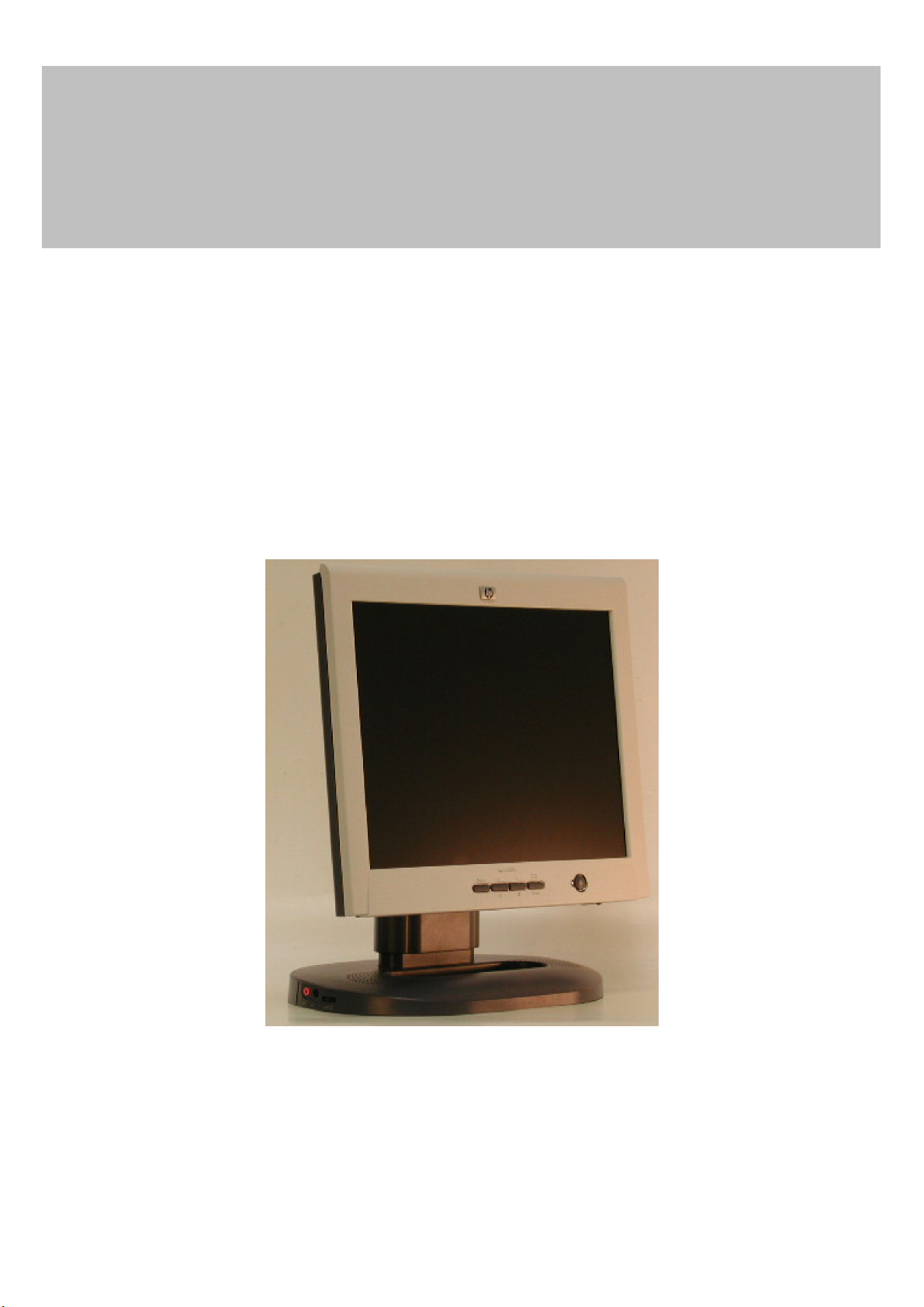
15" LCD Monitor
D5063
THESE DOCUMENTS ARE FOR REPAIR SERVICE INFORMATION ONLY. EVERY REASONABLE
EFFORT HAS BEEN MADE TO ENSURE THE ACCURACY OF THIS MANUAL; WE CANNOT
GUARANTEE THE ACCURACY OF THIS INFORMATION AFTER THE DATE OF PUBLICATION AND
DISCLAIMS RE LIABILITY FOR CHANGES, ERRORS OR OMISSIONS.
1
P/N : 41A50-169
Page 2
Vegas D5063 Service Manual
I. Revision List
Revision Date Change Description
A00 2002.01.18 Initial Version
A01 2002.01.23 Draft Version
A02 2002.02.06 1.) Add 4.1 Input Signal Connector
2.) Add 4.3 Power Supply Requirements
3.) Add 4.4 Panel Specification
4.) Add 5.1 Monitor Exploded View
5.) Improve 6.2 Inverter/Power Board Schematic Quality
6.) Improve 7.2, 7.3, 7.4 Layout Quality
7.) Add 8. Maintainability
A03 2002.03.05 Approved Version
A04 2002.07.28 1.) Add HSD Panel Part
2.) Update Part Lists
2
Page 3

Vegas D5063 Service Manual
II. Table of Contents
I. Revision List ............................................................................................................................. 2
II. Table of Contents .................................................................................................................... 3
1. MONITOR SPECIFICATIONS ............................................................................................ 5
2. LCD MONITOR DESCRIPTION ......................................................................................... 6
3. OPERATING INSTRUCTIONS ............................................................................................ 7
3.1 GENERAL INSTRUCTIONS ............................................................................................................... 7
3.2 CONTROL BUTTONS .......................................................................................................................... 7
3.3 ADJUSTING THE PICTURE ............................................................................................................... 8
4. Input/Outpt Specification ....................................................................................................... 9
4.1 Input Signal Connector .......................................................................................................................... 9
4.1.1 Analog D-SUB Connector ............................................................................................................. 9
4.1.2 DVI-D Connector ........................................................................................................................ 10
4.2 Preset Mode Timing .............................................................................................................................. 11
4.3 Power Supply Requirements ............................................................................................................... 12
4.3.1 Input Requirements ..................................................................................................................... 12
4.3.2 Output Requirements ................................................................................................................... 12
4.3.3 Compatible Power Adaptors List................................................................................................. 12
4.4 PANEL SPECIFICATION (AU L150X3M-1/-2-7 & HSD150MX41-C) ......................................... 13
4.4.1 Panel Feature ............................................................................................................................... 13
4.4.2 Display Characteristics ................................................................................................................ 13
4.4.3 Optical Characteristics................................................................................................................. 13
4.4.4 Parameter guide line for CCFL Inverter ...................................................................................... 14
5. Block Diagram ....................................................................................................................... 15
5.1 Monitor Exploded View ....................................................................................................................... 15
5.1.1 D5063M ....................................................................................................................................... 15
5.1.2 D5063A ....................................................................................................................................... 17
5.2 Software Flow Chart ............................................................................................................................ 19
5.3 Electrical Block Diagram ..................................................................................................................... 21
5.3.1 Main Board .................................................................................................................................. 21
5.3.2 Inverter/Power Board .................................................................................................................. 22
5.3.3 Audio Board (D5063M) .............................................................................................................. 23
6. Schematic ................................................................................................................................ 24
6.1 Main Board ........................................................................................................................................... 24
6.2 Inverter/Power Board .......................................................................................................................... 29
6.3 KeyPad Board ....................................................................................................................................... 31
6.4 Audio Board(D5063M) ......................................................................................................................... 32
7. PCB Layout ............................................................................................................................ 33
7.1 Main Board ........................................................................................................................................... 33
7.2 Inverter/Power Board .......................................................................................................................... 36
7.3 Keypad Board ....................................................................................................................................... 39
3
Page 4

Vegas D5063 Service Manual
7.4 Audio Board(D5063M) ......................................................................................................................... 40
8. Maintainability....................................................................................................................... 41
8.1 Equirements and Tools Requirement ................................................................................................. 41
8.2 Trouble Shooting ................................................................................................................................... 42
8.2.1 Main Board .................................................................................................................................. 42
8.2.2 Power/Inverter Board .................................................................................................................. 43
8.2.3 KeyPad Board .............................................................................................................................. 46
8.2.4 Audio Board (D5063M) .............................................................................................................. 47
8.3 Alignment Procedure ............................................................................................................................ 48
8.4 DDC Writing ......................................................................................................................................... 49
8.4.1 DDC Writing Procedure .............................................................................................................. 49
8.4.2 EDID Content .............................................................................................................................. 49
8.4.3 Serial Number Format ................................................................................................................. 50
9. Part Lists ................................................................................................................................ 51
4
Page 5

Vegas D5063 Service Manual
1. MONITOR SPECIFICATIONS
Driving system TFT Color LCD
LCD Panel Size 38.1cm(15.0")
Pixel pitch 0.297mm( H )x 0.297mm( V )
Viewable angle 120˚ (H) 100˚ (V)
Response time (typ.) 30 ms
Video Analog / DVI-D
Input Sync. Type H/V TTL Separate and Composite Sync.
H-Frequency 30kHz – 60kHz
V-Frequency 56-75Hz
Display Colors 16.7 million Colors
Dot Clock 80MHz
Max. Resolution 1024 x 768
Plug & Play VESA DDC2BTM
Power Consumption ON Mode
(D5063A)
ON Mode
(D5063M)
OFF Mode
(Audio Volume=0)
Maximum Screen Size
Power Source
Environmental
Operating Temp: 10°C to 35°C
<23W
<30W
<3W
Horizontal : 12.0”(304.128mm)
Vertical : 9.0”(228.096mm)
90~264VAC,47~63Hz
Considerations
Weight (N. W.)
D5063A 4.2Kgs Unit (net)
D5063M 4.7Kgs Unit (net)
Storage Temp.: -10°C to 60°C
Operating Humidity : 20% to 80%
5
Page 6
Vegas D5063 Service Manual
(
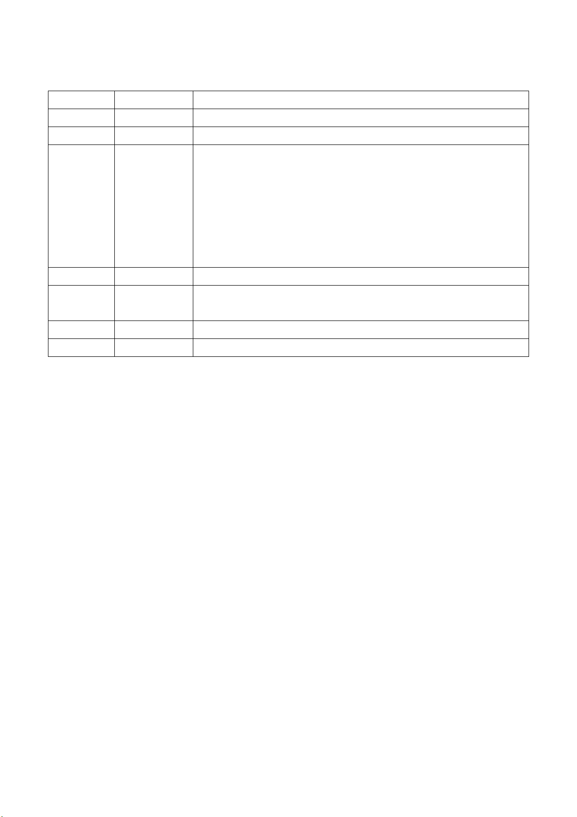
2. LCD MONITOR DESCRIPTION
The LCD MONITOR will contain an main board, an inverter/power board, keypad board and external adapter
which house the flat panel control logic, brightness control logic and DDC.
The Inverter board will drive the backlight of panel and the DC-DC conversion .
The Adapter will provides the 12V DC-power to inverter/power board .
AC-IN
90V-264V
Inverter Board
with DC-DC module)
ADAPTER
Monitor Block Diagram
CCFT Drive.
Main Board
Keyboard
Flat Panel and
CCFL backlight
HOST Computer
RS232 Connector
For white balance
adjustment in
factory mode
Video signal, DDC
6
Page 7
Vegas D5063 Service Manual
3. OPERATING INSTRUCTIONS
3.1 GENERAL INSTRUCTIONS
Press the power button to turn the monitor on or off. The other control buttons are located at front panel of the monitor. By changing
these settings, the picture can be adjusted to your personal preferences.
The power cord should be connected.
-
Connect the video cable from the monitor to the video card.
-
Press the power button to turn on the monitor, the power indicator will light up.
-
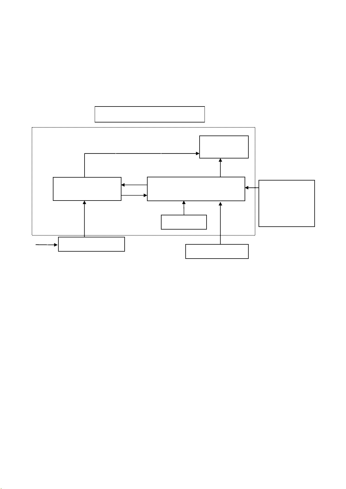
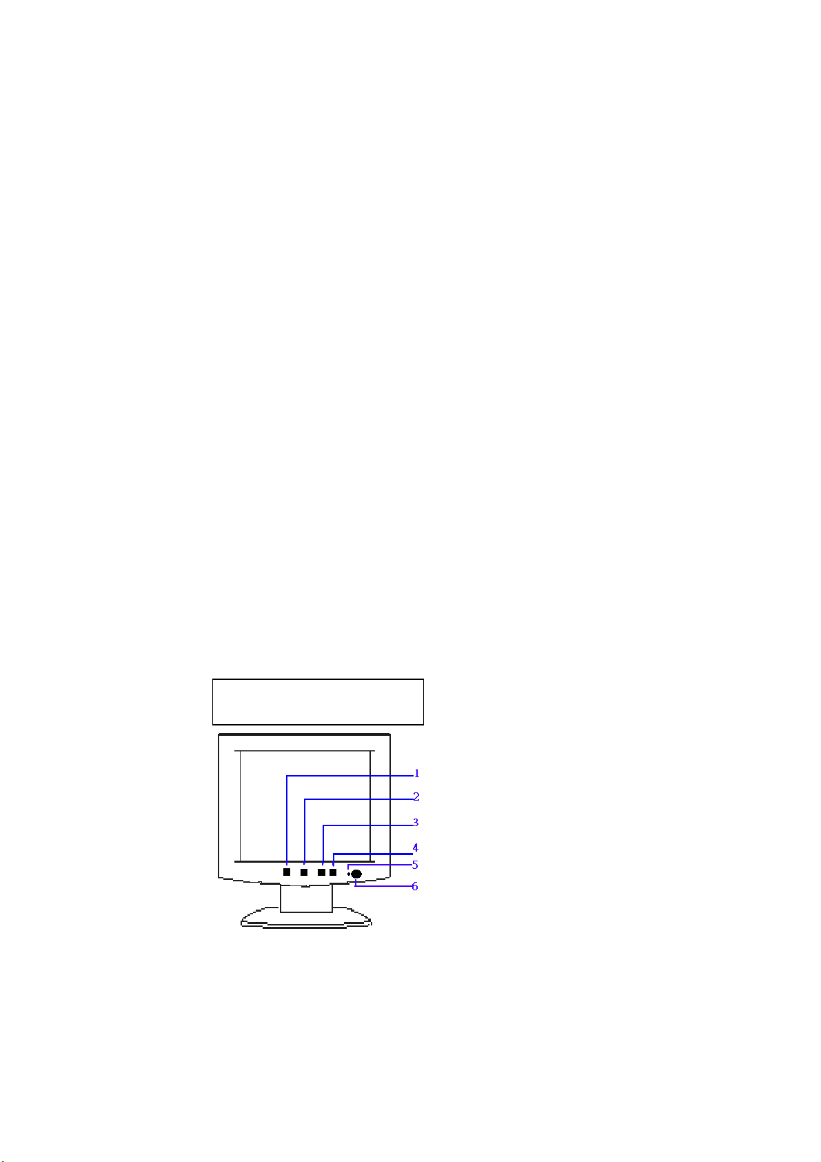
3.2 CONTROL BUTTONS
Power Button:
-
When pressed, the monitor enters the off mode, and the LED turns blank. Press again to restore normal status.
- Left / Right Button:
The Left/Right Button is used to control the monitor functions. Press to switch functions or adjust settings.
- Auto Adjust Key:
The Auto Adjust Key is used to automatically set the H Potision, V Potision, Clock and Phase.
- Power Indicator:
Green — Power On mode.
Orange — Power Saving mode.
Blank — Power Off Mode.
AUDIO BASE CONTROL (D5063M ONLY ) :
- Volume
Adjustable Audio volume.
- Earphone-jack
- Micphone-jack
CONTROL Buttons
Menu
< / Brightness
> / Contrast
Auto/Select
LED indicator
Power Button
7
Page 8
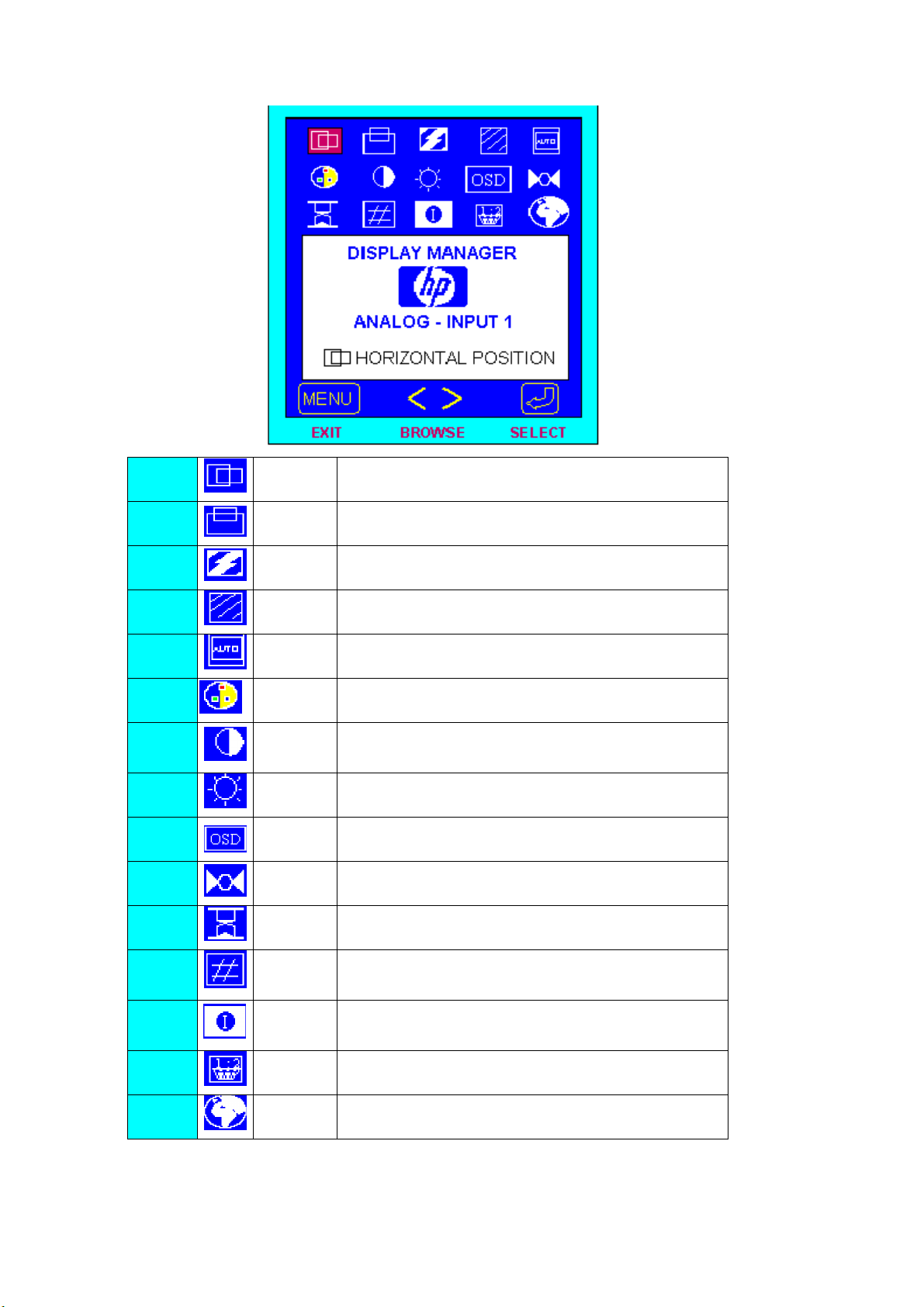
3.3 ADJUSTING THE PICTURE
Vegas D5063 Service Manual
1.
2.
3.
4.
5.
6.
7.
8.
9.
10.
11.
12.
H Position Adjust the horizontal position of the picture.
V Position Adjust the vertical position of the picture.
Phase Adjust picture Phase.
Clock Adjust picture Clock.
Auto Config Automatically set the H Potision, V Potision, Clock and Phase
Color
Contrast Adjust the picture contrast.
Brightness Adjust the picture brightness.
OSD
Manager
Mode Recall Restored H/V Position, Clock and Phase.
Backlight
info
Serial
Number
Choose color temperature of 9300K / 6500K / 5800K / User
Color
Adjust OSD function of Protected OSD(password : 040990),
OSD Timeout, Info On/Off, OSD H/V Position.
Display the Backlight Elapsed Time.
Display Serial Number.
13.
14.
15.
Mode Info
Input Priority Select Signal Input Priority
Language Select Language
Preset and User Mode List.
8
Page 9
Vegas D5063 Service Manual
4. Input/Outpt Specification
4.1 Input Signal Connector
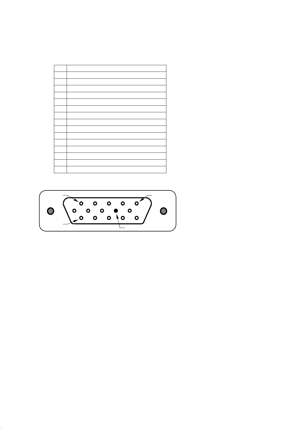
4.1.1 Analog D-SUB Connector
Video Cable Pinout
PIN SIGNAL
1 Red Video
2 Green Video
3 Blue Video
4 TXD (for factory alignment)
5 Return
6 Red GND
7 Green GND
8 Blue GND
9 +5V (for reading EDID file when monitor is turned off)
10 Sync GND
11 RXD (for factory alignment)
12 Bidirectional DDC Data (SDA)
13 Horizontal Sync
14 Vertical Sync
15 DDC Data Clock (SCL)
Video Cable Connector Pins
9
Page 10
Vegas D5063 Service Manual
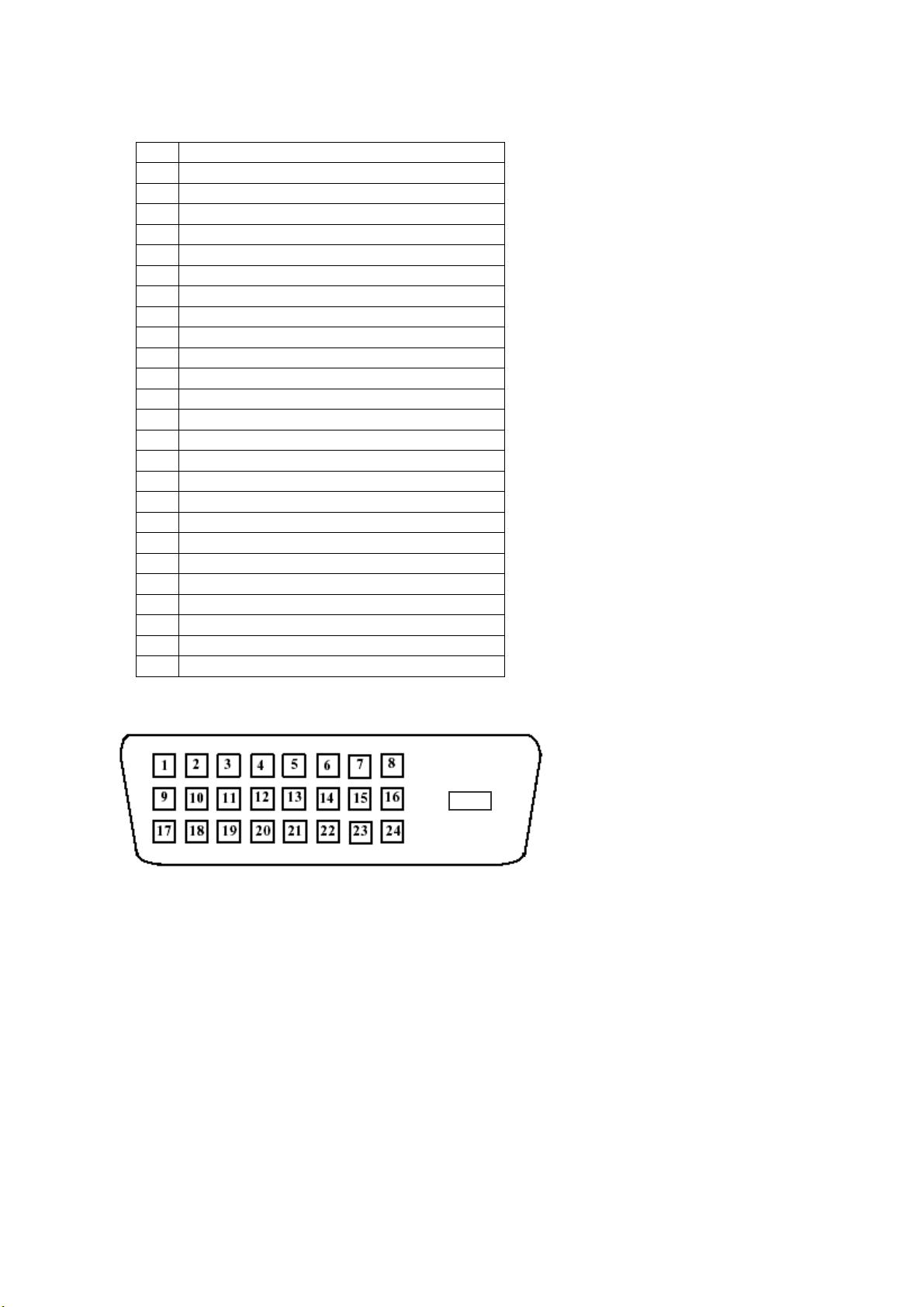
4.1.2 DVI-D Connector
DVI-D Connector to be compliant to the latest DVI-DDWG specification version available.
Video Cable Pinout
PIN SIGNAL
1 TMDS RX2-
2 TMDS RX2+
3 TMDS RX2 GND
4 NC
5 NC
6 DDC Data Clock (SCL)
7 Bidirectional DDC Data (SDA)
8 NC
9 TMDS RX1-
10 TMDS RX1+
11 TMDS RX1 GND
12 NC
13 NC
14 +5V
15 GND
16 Hot Plug Detect
17 TMDS RX0-
18 TMDS RX0+
19 TMDS RX0 GND
20 NC
21 NC
22 TMDS RXC GND
23 TMDS RXC+
24 TMDS RXC-
C5 NC
Video Cable Connector Pins
C5
10
Page 11
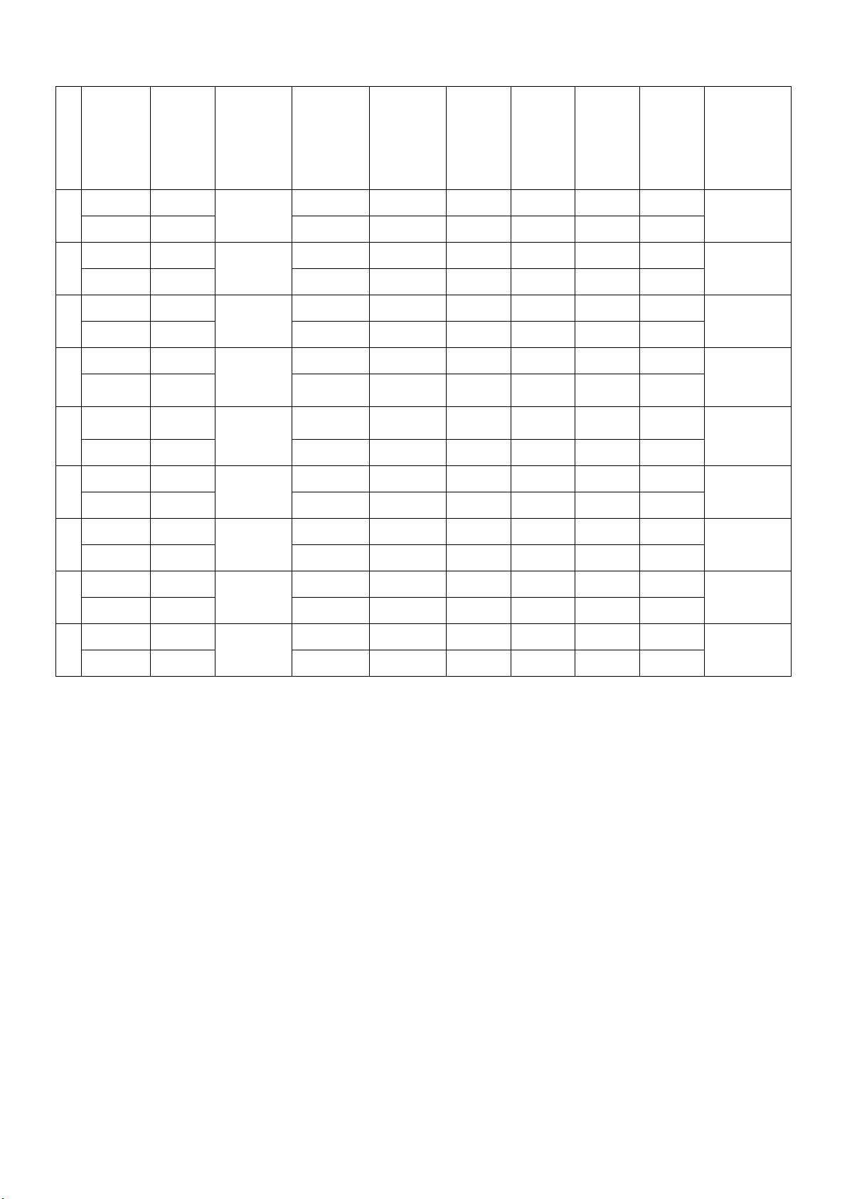
4.2 Preset Mode Timing
Vegas D5063 Service Manual
# Synchro Polarity Dot Clock
(MHz)
H(Pixels) +
1
V(Lines) - 70.08 449 350 38 2 59
H(Pixels) -
2
V(Lines) + 59.94 525 480 10 2 33
H(Pixels) -
3
V(Lines) - 75 500 480 1 3 16
H(Pixels) -
4
V(Lines) - 70.8 449 400 12 2 35
H(Pixels) +
5
V(Lines) + 60.317 628 600 1 4 23
H(Pixels) +
6
V(Lines) + 75.0 625 600 1 3 21
25.175
25.175
31.5
28.321
40.0
49.5
Frequency
(Khz)/(Hz)
31.469 800 640 16 96 48
31.469 800 640 16 96 48
37.5 840 640 16 64 120
31.468 900 720 18 108 54
37.879 1056 800 40 128 88
46.875 1056 800 16 80 160
Total
Period
(Pixels)
Display
Period
(Pixels)
Front
Porch
Period
(Pixels)
Synchro
Period
(Pixels)
Back
Porch
Period
(Pixels)
Resolution
640 x 350
640 x 480
640 x 480
720 X 400
800 x 600
800 x 600
H(Pixels) +/-
7
V(Lines) +/- 74.55 667 624 1 3 39
H(Pixels) -
8
V(Lines) - 60.0 806 768 3 6 29
H(Pixels) -
9
V(Lines) - 75.029 800 768 1 3 28
57.283
65.0
78.75
49.725 1152 832 32 64 224
832 x 624
48.363 1344 1024 24 136 160
1024 x 768
60.123 1312 1024 16 96 176
1024 x 768
11
Page 12
Vegas D5063 Service Manual
)
p
4.3 Power Supply Requirements
4.3.1 Input Requirements
PARAM ETER RANGE CONDITION
Input Voltage 90 to 264 VAC RMS Universal input full range
Input Frequency 47 Hz to 63 Hz 110V AC 60Hz; 220V AC 50 Hz
Input Current Less than 1.2 Amps RMS Input voltage 90 VAC RMS ; 60 Hertz. Parameter
must be reached within 3 seconds of turn-on.
Less than 0.8 Amps RMS Input voltage 180 VAC RMS ; 50 Hertz. Parameter
must be reached within 3 seconds of turn-on.
Input Power Less than 55 Watts
Power factor > 0.5 Input voltage 120 VAC RMS ; 60
Hertz
Inrush Current Less than 30 A peak Input voltage 110 VAC RMS ; 60 Hertz at all
Less than 70 A peak Input voltage 240 VAC RMS ; 50 Hertz at all
Input Fusing Fuse should be located internal to the
adapter, easily accessible when the
cover is removed
Leakage Current Less than 3.5 mA Input voltage 264 Volts RMS ; 50 Hertz
Hi-Pot Primary to secondary 1.5KVAC for 1 Minute(leakage current 10mA)
Primary to Saft Ground 1.5KVAC for 1 Minute(leakage current 10mA)
Phase(0, 90, 180, 270 degree)
Phase(0, 90, 180, 270 degree)
Fuse must be UL/CSA approved. Fuse value must no
have to change for 115 VAC or 230 VAC operation
1.8KVAC for 1 Minute(leakage current 10mA)
3.0KVAC for 1 Minute(leakage current 10mA)
without Y-cap & Coupling cap.
1.8KVAC for 1 Minute(leakage current 10mA
4.3.2 Output Requirements
PARAMETER RANGE CONDITION
Ripple & noise 170mVpp at 12VDC Input voltage : 100VAC at 60Hz 240VAC at 50Hz
* Ripple and noise are meausred
Output current
rotection
Leakage Current Less than 0.25 mA Input voltage 100 Volts RMS ; 60 Hertz
Less than 0.5 mA Input voltage 254 Volts RMS ; 50 Hertz
Output Power At least 40 Watts in max conditions
4.3.3 Compatible Power Adaptors List
1.) Delta ADP-40TB
2.) Delta ADP-50XB
3.) Li Shin LSE9901B1250
less than 5.0 A at 12.0 VDC Current exceeds maximum rateing more than 20%
12
Page 13
Vegas D5063 Service Manual
4.4 PANEL SPECIFICATION (AU L150X3M-1/-2/-7 & HSD150MX41-C)
4.4.1 Panel Feature
-XGA 1024(H) x 768(V) resolution
-2 CCFLs (Cold cathode Fluorescent Lamp)
-High contrast ratio, high aperture ratio
-Wide viewing angle
-High speed response
-Low power consumption
4.4.2 Display Characteristics
ITEMS Unit
Screen diagonal [mm] 381 (15”) 381 (15”)
Outline dimension [mm] 331.3 x 249.0 x 11.6 typ. 336 x 249 x 13.5
Display Area [mm] 304.128 (H) x 228.096(38.1cm diagonal) 304.1(H) x 228.1(38.1cm diagonal)
Resolution 1024(R,G,B x 3) x 768 1024(R,G,B x 3) x 768
Pixel Pitch [mm] 0.297 x 0.297 0.297 x 0.297
Pixel Arrangement R.G.B. Vertical Stripe R.G.B. Vertical Stripe
Display Mode TN mode, Normally White Normally White
Typical white Luminance. [cd/m2] 200nit (typ) @6.5mA,
Brightness uniformity 80% typ. 70% min
Luminance uniformity 1.7 max.
Brightness variation 15% max.
Crosstalk (at 60Hz and
75 Hz)
Contrast Ratio 350 : 1 typ., 250:1 min 350 : 1 typ., 250:1 min
Support Colors 262,144 colors (6-bit for R,G,B) 262,144 colors (6-bit for R,G,B)
Chromaticity(CIE1931)
White-x
White-y 0.329 0.340
Color Gamut 60% typ., of NTSC coverage
Viewing angle 60(left),60(right),40(up),60(down) 60(left),60(right),40(up),50(down)
Response Time [msec] 30ms typ. (Tr +Tf) 35ms typ. (Tr +Tf)
Nominal Input
Voltage VDD
Power Consumption
(VDD line + CCFL line)
Electrical Interface TTL 2 port TTL 2 port
Frame rate [Hz] 60Hz typ., 75Hz max. 60Hz typ., 75Hz max.
Weight [Gram
Mounting method Side / Front mounting Side / Front mounting
Surface treatment Anti-glare, hard coating (3H) Anti-glare, hard coating (3H)
Temperature Range
Operating
Storage (Shipping)
1.2% max. 1.2% max.
[Volt] +3.3 V +3.3 V
[Watt] 11 W(typ.) @6.5mA
s]
o
[
C]
o
[
C]
AU L150X3M-1/-2/-7 HSD150MX41-C
240nit (typ) @8mA
0.313 0.320
1100 typ. 1100 typ.
0 to +50
-20 to +60
SPECIFICATIONS
200nit (typ) @
250nit (typ) @8mA
11 W(typ.) @6.5mA
0 to +50
-20 to +60
6.5mA,
4.4.3 Optical Characteristics
The optical characteristics are measured under stable conditions at 25℃ (Room Temperature):
Item Unit Conditions
Viewing Angle
CR: Contrast Ratio
[degree]
[degree]
[degree]
[degree]
Horizontal (Right)
CR = 10 (Left)
Vertical (Upper)
CR = 10 (Lower)
AU L150X3M-1/-2/-7 HSD150MX41-C
Min. Typ. Max. Min. Typ. Max.
50
50
30
50
60
60
40
60
13
50
50
30
40
60
60
40
50
Page 14
Vegas D5063 Service Manual
A
A
A
A
2
Contrast ratio Normal Direction 250 350 - 250 350 -
Response Time [msec]
[msec]
Raising Time Ton
( 10%-90% )
Falling Time Toff
( 90%-10% )
- 8 15 10 15
- 22 30 25 35
[msec] Raising + Falling - 30 45 35 50
Color / Chromaticity Red x 0.587 0.617 0.647 0.60 0.63 0.66
Coordinates (CIE) Red y 0.317 0.347 0.377 0.31 0.34 0.37
Green x 0.260 0.290 0.320 0.27 0.30 0.33
Green y 0.563 0.593 0.623 0.56 0.59 0.62
Blue x 0.118 0.148 0.178 0.12 0.15 0.18
Blue y 0.07 0.100 0.130 0.08 0.11 0.14
Color Coordinates (CIE) White White x 0.283 0.313 0.343 0.29 0.32 0.35
White y 0.299 0.329 0.359 0.31 0.34 0.37
Brightness Uniformity [%] 75 80 - 70
White Luminance at CCFL
8.0mA
White Luminance at CCFL
[cd/m
2
]
200
170
240
200
-
-
200 - 250
-
-
-
6.5mA
Crosstalk ( in 75Hz) [%] 1.2 1.2
4.4.4 Parameter guide line for CCFL Inverter
AU L150X3M-1/-2/-7 HSD150MX41-C
Symble Parameter
(L255) White Luminance 170 @
Min Typ Max Min Typ Max
6.5m
200 @
6.5m
- 200 @
8.0m
250 @
8.0m
- [cd/m
IRCFL CCFL operation range 3.0 8.0 8.5 3.0 8.0 8.5 [mA]
Units Condition
] (Ta=25℃)
(Ta=25℃)
rms
Note 1
ICFL CCFL Inrush current - - 20 - - 20 [mA]
fCFL CCFL Frequency 40 55 60 50 55 80 [KHz] (Ta=25℃)
ViCFL
(25℃)
CCFL Ignition Voltage
1000
925
[Volt]
rms
(Ta= 25℃)
(referenc
e)
ViCFL
(0℃)
CCFL Ignition Voltage
1300
1430
[Volt]
rms
(Ta= 0℃)
(referenc
e)
VCFL CCFL Discharge Voltage
(Reference)
PCFL CCFL Power
consumption @ 6.5mA
630 690 570 627 [Volt]
rms
(Ta=25℃)
8.2 10 8.2 10 [Watt] (Ta=25℃)
Note 1: CCFL life time 30,000hr under 8mA,it’s defined as when the brightness is reduced by half.
14
Page 15

5. Block Diagram
5.1 Monitor Exploded View(AUX3M PANEL)
5.1.1 D5063M
Vegas D5063 Service Manual
15
Page 16

Vegas D5063 Service Manual
16
Page 17
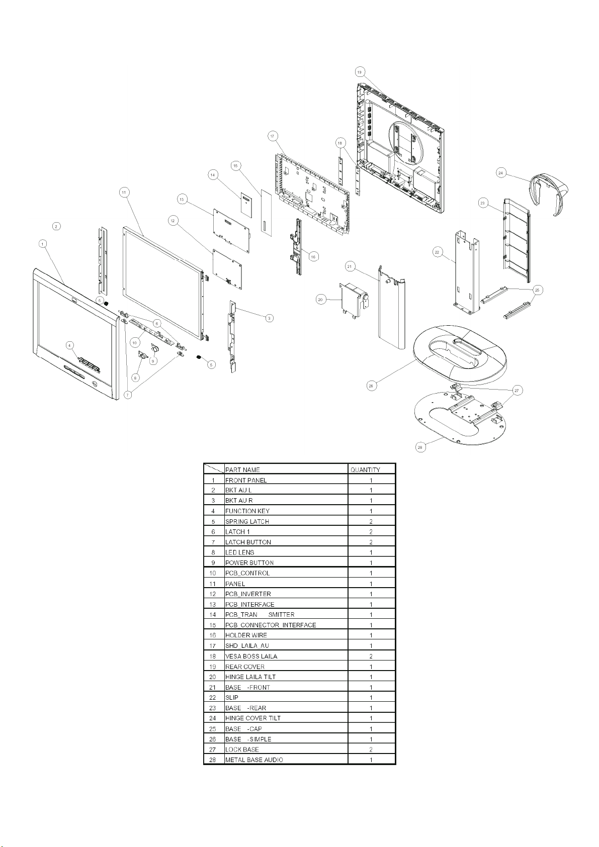
5.1.2 D5063A
Vegas D5063 Service Manual
17
Page 18

Vegas D5063 Service Manual
18
Page 19
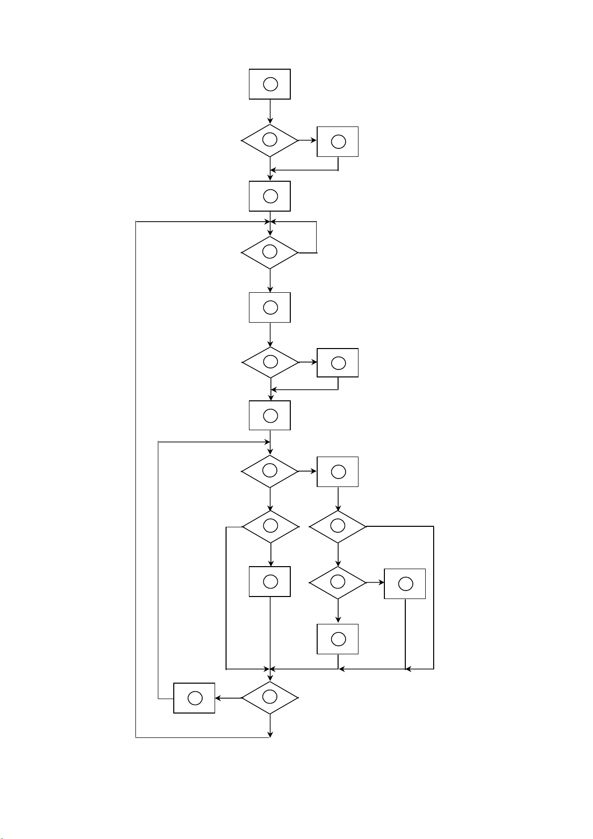
5.2 Software Flow Chart
2
10
12
643
8
9
141113
1516
1719
18
Vegas D5063 Service Manual
1
5
7
19
Page 20

Vegas D5063 Service Manual
1) MCU initialize.
2) Is the eeprom blank ?
3) Program the eeprom by default values.
4) Get the PWM value of brightness from eeprom.
Check the pin PANEL1 and PANEL2 to tell which panel is adapted.
5) Is the power key pressed ?
6) Clear all global flags.
7) Are the AUTO and SELECT keys pressed ?
8) Enter factory mode.
9) Save the power key status into eeprom.
Turn on the LED and set it to green color.
Scaler initialize.
10) In standby mode ?
11) Update the life time of back light.
12) Check the analog and digital port, are there any signals coming ?
13) Does the scaler send out a interrupt request ?
14) Wake up the scaler.
15) Are there any signals coming from analog or digital port ?
16) Display "No Signals" message. And go into standby mode after the message disappear.
17) Program the scaler to be able to show the coming mode.
18) Process the OSD display.
19) Read the keyboard. Is the power key pressed ?
20
Page 21

5.3 Electrical Block Diagram
5.3.1 Main Board
Vegas D5063 Service Manual
EEPROM
24C02 (IC11)
DVI-SCL,
DVI-SDA
Scaler ADE2100V2
(Include ADC and OSD)
(IC1)
SiI141
(IC5)
RX2+, RX2-,
RX1+, RX1-,
RX0+, RX0-,
RXC+, RXC-
DVI-D
Connector
(CON2)
RED, GREEN,
BLUE
ADE-SCL,
ADE-SDA
Hsync,
Vsync
Hsync,
Vsync
D-Sub
Connector
(CON3)
MCU
ST72774
(IC8)
RXD,
TXD
DB15-SCL,
DB15-SDA
EEPROM
24C16
(IC9)
EPR-SCL, EPR-SDA
EEPROM
24C02 (IC10)
OSD
Control
Interface
(CON6)
21
Page 22

5.3.2 Inverter/Power Board
Vegas D5063 Service Manual
Inverter Block Diagram
Vin
Vin
Buck Connector
Driver
Circuit
Driver
Circuit
Dimming control
Parallet-reso nant
inverter
Dimm ing control
(PW M )
(阀菠瓜)
Parallet-resonant
inv erter
CCFL
PWM
Power Block Diagram
+12V
Regulator
SI-8050S
+5V
(U101)
Regulator
SI-3033SD –3.3V
+3.3V
(U102)
22
Page 23

5.3.3 Audio Board (D5063M)
Vegas D5063 Service Manual
MIC. CABLE
TO PC
AUDIO IN
TO PC
DC 12V
INPUT
M753
M754
DC IN
AUDIO1
TDA7496L
L-IN
R-IN
CN719
+12V TO M/B
L-OUT
R-OUT
RX1 75R
RX2 75R
CN717
CN720
AUDIO2
CN715
CN716
1
VOLUME CONTROL
BLOCK
AOC (Top Victory) Electronics Co., Ltd.
Title
Size Document Number Rev
Date: Sheet
AUDIO BLOCK DIAGRAM
A
M752
TO EXTRACT
MICROPHONE
M751
EARPHONE
JP2
TO SPEAKER
HP-VEGAS
TO
R / L
34Tuesday, December 11, 2001
A
of
23
Page 24

6. Schematic
6.1 Main Board
Page-8
SIGNAL-INPUT
CLK
RED
BLUE
GREEN
TXD
RXD
HS
VS
PHSYNC
PVSYNC
PDE
PHFCLK
A1BLU[0..7]
A1GRN[0..7]
A1RED[0..7]
B1BLU[0..7]
B1GRN[0..7]
B1RED[0..7]
DVD1
DVD0
/VGA_CON
+5V
+3.3V
Page-5
HS
VS
PHSYNC
PVSYNC
PDE
PHFCLK
A1BLU[0..7]
A1GRN[0..7]
A1RED[0..7]
B1BLU[0..7]
B1GRN[0..7]
B1RED[0..7]
DVD1
DVD0
SCALER AD2100V2
SILL-141-BC Page-3
RED
GREEN
BLUE
CLK
AG[0..7]
AR[0..7]
BG[0..7]
BR[0..7]
BR[0..7]
AR[0..7]
BG[0..7]
AG[0..7]
+12V
Vegas D5063 Service Manual
Table of Contents:
Page
Description:
Title Page
1
ADE2100V2 I/O Interface
2
3
ADE2100V2 Decoupling
Power Supply Interface
4
5
Analog Input Interface
6
Digital Input Interface
Panel Output Interface
+3.3V
+5V
MPU_SDA
MPU_SCL
VCLK
AB[0..7]
BB[0..7]
EXVCLK
Page-6
VCLK
EXVCLK
AB[0..7]
BB[0..7]
AD-SCL
AD-SDA
+3.3V
GND
+5V
MICRO CONTROLLER
MPU_SDA
MPU_SCL
AD-SCL
AD-SDA
/VGA_CON
Page-3
EL-INVERTER
BR[0..7]
AR[0..7]
BG[0..7]
AG[0..7]
RXD
A-ADJ
A-ADJ
TXD
+5V
GND
EN
EN
GND
+12V
7
8
9
POWER Page-7
+5V
+3.3V
GND
+12V
MCU Interface
Screw Holes & History
ADE2100V2 HP/AOC Design Rev. 0.3
ADE2100V2 HP/AOC Board Design
Title
Title Page
Size Document Number Rev
VEGAS 0.3
Date: Sheet
19Monday, January 21, 2002
of
24
Page 25

ORB[7:0][7]
OGB[7:0][7]
OBB[7:0][7]
ORA[7:0][7]
OGA[7:0][7]
OBA[7:0][7]
OVSYNC[7]
OHSYNC[7]
ODE[7]
ODCLK[7]
ORB7
ORB6
ORB5
ORB4
ORB3
ORB2
ORB1
ORB0
OGB7
OGB6
OGB5
OGB4
OGB3
OGB2
OGB1
OGB0
OBB7
OBB6
OBB5
OBB4
OBB3
OBB1
OBB0
ORA7
ORA6
ORA5 OBB5
ORA4
ORA3
ORA2
ORA1
ORA0
OGA7
OGA6
OGA5
OGA4
OGA3
OGA2
OGA1
OGA0
OBA7
OBA6
OBA5
OBA4
OBA3
OBA2
OBA1
OBA0
OVSYNC
OHSYNC
ODE
ODCLK
Output Mapping 1
Vegas D5063 Service Manual
Input/Output Interface
DINCLKA
DHSYNCA
DVSYNCA
DENABA
BRIGHTNESS[4]
AB1
AA2
AC22D2C23D1F1
B11
T4T3T2T1F2E1F4
ORB0
AF10
OD0
ORB1
AE10
OD1
ORB2
AF11
OD2
ORB3
AE11
OD3
ORB6
AC11
OD4
ORB4
AF12
OD5
ORB5
AE12
OD6
ORB7
AC12
OD7
OGB0
AF13
OD8
OGB1
AE13
OD9
OGB6
AC13
OD10
OGB2
AF14
OD11
OGB3
AE14
OD12
OGB4
AF15
OD13
OGB5
AE15
OD14
OGB7
AC15
OD15
OBB0OBB2
AE16
OD16
OBB1
AF16
OD17
OBB6
AC16
OD18
OBB2
AF17
OD19
OBB3
AE17
OD20
OBB4
AF18
OD21
AE18
OD22
ORA0
AF19
OD23
OBB7
AC18
OD24
ORA1
AE19
OD25
ORA3
AE20
OD26
ORA2
AD19
OD27
AC19
ORA6
OD28
ORA4
AE21
OD29
OGA0
AF22
OD30
OGA1
AE22
OD31
ORA5
AD21
OD32
OGA2
AF23
OD33
ORA7
AC21
OD34
AD22
OGA6
OD35
OGA3
AE26
OD36
OGA4
AD25
OD37
OGA5
AD26
OD38
OBA0
AC24
OD39
OBA1
AC25
OD40
OBA2
AC26
OD41
OBA3
AB24
OD42
AA23
OGA7
OD43
AA24
OBA6
OD44
OBA4
AA25
OD45
OBA5
AA26
OD46
Y25
OD47
Y26
OD48
W26
OD49
OBA7
W24
OD50
W25
OD51
E2
PWM7
PWM6
PWM5
PWM4
PWM3
PWM2
PWM1
PWM0
AINCLK
ACLAMP
TSTACLK
TSTMCLK
REFVSYNC
MD47
MD46
MD45
MD44
MD43
MD42
MD41
MD40
MD39
MD38
MD37
MD36
MD35
MD34
V25
V23
U26
U25
T26
MD33
T25
T24
T23
R25
R24
R23
P26
P24
P23
N26
N25
AD2
AD9
AE9
B12
C12
OSDR
TSTDCLK
MD32
MD31
MD30
A19
D19
C19
AC2
D12
A11
OSDB
OSDG
OSDEN
DENABB
DINCLKB
DDC_SCL
DDC_SDA
DVSYNCB
DHSYNCB
MD29
MD28
MD27
MD26
MD25
MD24
MD23
MD22
MD21
MD20
MD19
B19
B18
D18
C18
A17
B17
A16
B16
C16
A15
B15
AE3
AB3
AE1
DRB7
DRB6
MD18
MD17
MD16
C15
D15
M26
AE2
AF2
AF1
AC3
AD1
DRB5
DRB4
DRB3
DRB2
DRB1
DRB0
IC1A
ADE2100V2
BGA388
Input/Output Interface
MD15
MD14
MD13
MD12
MD11
MD10
M25
M24
L26
L25
L23
AF5
AE5
AF3
AF4
AD5
AD6
AE4
AD4
DGB7
DGB6
DGB5
DGB4
DGB3
DGB2
DGB1
DGB0
MD9
MD8
MD7
MD6
MD5
MD4
MD3
MD2
MD1
K26
K25
C22
B22
D21
A22
B21
A21
B20
A20
A1
AF9
MD0
B10A9C2
AF7
AE8
AD8
AF8
AF6
AE7
AE6
DBB7
DBB6
DBB5
DBB4
DBB3
DBB2
DBB1
DBB0
DENABA
DINCLKA
DVSYNCA
DHSYNCA
MA11
MA10
MA9
MA8
MA7
MA6
MA5
MA4
MA3
MA2
MA1
E24
TP1
TestPad
TP2
TestPad
TP3
TestPad
F23
MA0
J23
H25
G25
H24
H23
F25
E26
E25
F24
D25
MCLKOUT
1
LLHSYNC
1
LLCOAST
1
DGA7
DGA6
DRA2
DRA4
DRA1
DRA3
DRA5
DRA6
DRA7
DRA0
B9A8C9D8C8D9A7B8A6B5B4D5D6A5B6C6A4C4C1B3C5A3B2
DRA7
DRA6
DRA5
DRA4
DRA3
DRA2
DRA1
DRA0
DGA7
MRAS#
MCAS#
MWE#
MCS#
MDQM
MCLKE
MCLK
MCLKI
C25
C11
E23
A26
B26
B25
J24
J26
J25
DBA5
DBA4
DGA0
DGA5
DGA2
DGA1
DBA3
DGA3
DGA4
DBA7
DBA6
DBA7
DBA6
DBA5
DGA6
DGA5
LLHSYNC
LLCOAST
D11
DBA4
DGA4
DGA3
DGA2
DGA1
DGA0
SCS#
SCAN_EN
TEST
C14
A10
A13
A24
D22
AD23
AE24
DBA1
DBA2
DBA3
DBA2
NCNCNCNCNCNCNC
L2M2U1
DBA0
B1
DBA1
DBA0
ASTAB
RESET#
AVSYNC
AHSYNC
SSREF
RVREFH
GVREFH
BVREFH
RVREFM
GVREFM
BVREFM
RVREFL
GVREFL
BVREFL
XCLK
B14
DINCLKA [5]
DHSYNCA [5]
DVSYNCA [5]
DENABA [5]
DRA[7:0] [5]
DGA[7:0] [5]
DBA[7:0] [5]
A3.3V
+5V
C1
C2
R1
1nF
10nF
4.7k
C0603
C0603
R0603
ASTAB
H4
ADE-SDA
B13
SDA
ADE-SCL
A12
SCL
ADE-IRQ
A14
IRQ
ADE-RESET
D14
VSYNC-IN
E3
HSYNC-IN
F3
RAIN
W1
RAIN
GAIN
P1
GAIN
J1
BAIN
BAIN
L4
M1
A3.3V
SSIN
RVH
V3
GVH
P2
BVH
J4
RVM
Y2
GVM
N2
BVM
J2
RVL
V4
GVL
N4
BVL
J3
AISET
K2
AISET
RVBS
GVBS
BVBS
XCLK
R2
2.1k, 1%
W2
R0603
R2
H2
XCLK [8]
ADE-SDA [8]
ADE-SCL [8]
ADE-IRQ [8]
ADE-RESET [8]
ADE-AVSYNC [6,8]
ADE-AHSYNC [6,8]
C3 0.1uF
RED [6]
C127 4.7uF
C0805Y5V, 10V
C4 0.1uF
GREEN [6]
C128 4.7uF
C0805Y5V, 10V
C5 0.1uF
BLUE [6]
C0603
C129 4.7uF
C0805Y5V, 10V
C6
1nF
C10
C9
C8
C7
1nF
1nF
C12
C11
C13
C14
1nF
1nF
1nF
1nF
1nF
1nF
C0603
ADE2100V2 HP/AOC Board Design
Title
ADE2100V2 Input and Output Interface
Size Document Number Rev
VEGAS 0.3
Date: Sheet of
DECOUPLING CAPS &
POWER DISTRIBUTION
DGND
T16
T15
T14
T13
T12
T11
R16
R15
R14
R13
R12
R11
P16
P15
P14
P13
P12
P11
N16
N15
N14
N13
N12
N11
M16
M15
M14
M13
M12
M11
L16
L15
L14
L13
L12
VSS
VSS
VSS
VSS
VSS
VSS
VSS
VSS
VSS
VSS
VSS
VSS
VSS
VSS
VSS
VSS
VSS
VSS
VSS
VSS
VSS
VSS
VSS
VSS
VDD6
AD7
VDD
AD3
C15
0.1uF
C0603
C24
0.1uF
D3.3V
12
+
SECCB
12
+
SECCB
C37
C36
10uF
10uF
C1206
Y5V, 10V
C35
C34
+
NP
10uF
SECCB
12
C0603
C47
0.1uF
C0603
C17
C18
C16
0.1uF
0.1uF
0.1uF
0.1uF
0.1uF
0.1uF
A3.3V
0.01uF
C0603
C0603
C0603
C25
C26
C27
0.1uF
0.01uF
C0603
C0603
C0603
C30
C32
C31
0.1uF
0.1uF
C0603
C0603
C0603
C50
C48
C49
0.01uF
0.1uF
C0603
C0603
C0603
C52
C54
C53
0.1uF
0.1uF
C0603
C0603
C0603
C60
C59
0.1uF
0.1uF
C0603
C0603
FB5
12
L0805
C66
0.1uF
C0603
VDD
AC6
C19
VDD
0.01uF
AC5
VDD
C0603
AB4
VDD
AB2
VDD
AA3
VDD
Y3
VDD
VDD5
AF20
VDD
AD20
VDD
C28
AD17
VDD
0.01uF
AD15
VDD
C0603
AD14
VDD
AD13
VDD
AD11
VDD
AD10
VDD
VDD4
AF24
VDD
AE23
VDD
C33
AD24
VDD
0.01uF
AB25
VDD
C0603
Y24
VDD
U24
VDD
P25
VDD
VDD3
N24
VDD
L24
VDD
C51
K24
VDD
0.01uF
G26
VDD
C0603
G24
VDD
C26
VDD
C24
VDD
A23
VDD
VDD2
C21
VDD
C20
VDD
C55
D16
VDD
0.01uF
C17
VDD
C0603
C13
VDD
VDD1
C10
VDD
C7
VDD
A2
C61
VDD
0.01uF
C0603
LLVDD
C3
LLVDD
C67
0.01uF
C0603
D4
LLVSS
VSS
VSS
VSS
VSS
VSS
VSS
A18
AA4
AB23
AB26
AC1
AC10
A25
Thermal Grounds
IC1B
ADE2100V2
BGA388
POWER INTERFACE
VSS
VSS
VSS
VSS
VSS
VSS
VSS
VSS
VSS
VSS
VSS
AC14
VSS
AC17
AC20
AC23
AC4
AC7
AC8
AC9
AD12
AD16
AD18
VSS
VSS
VSS
VSS
VSS
VSS
VSS
VSS
VSS
VSS
VSS
AF21B7D10
D13
D17
D20
D23
D24
D26D7F26
AE25
L11
VSS
VSS
VSS
VSS
VSS
VSS
VSS
VSS
VSS
VSS
VSS
GVDDL
G2
GVDDL
G3
GVDDL
GVDDR
W3
GVDDR
AA1
GVDDR
GVSSL
GVSSL
GVSSR
GVSSR
AVDD
AVDD
AVDD
AVDD
AVDD
AVDD
AVDD
AVDD
AVDD
AVSS
AVSS
AVSS
AVSS
AVSS
AVSS
AVSS
AVSS
AVSS
AVSS
AVSS
AVSS
APLL_VDD
APLL_VSS
DPLL_VDD
MPLL_VDD
DPLL_AVSS
MPLL_AVSS
VSS
VSS
VSS
VSS
VSS
VSS
VSS
VSS
VSS
VSS
VSS
VSS
VSS
G23
H26
VSS
K23
M23
N23
R26
U23
V24
V26
W23
Y23
Y4
C20
G1
0.01uF
G4
C0603
W4
Y1
H1
K3
AVDD1
L1
M3
AVDD2
N1
P3
AVDD3
R4
U2
U3
H3
K1
C38
0.01uF
K4
C0603
L3
M4
N3
P4
R1
R3
U4
V1
V2
E4
C56
0.01uF
C0603
D3
DPLL_VDD
AF25
B23
MPLL_VDD
C62
0.01uF
C0603
AF26
B24
A3.3V
C21
C22
0.1uF
0.01uF
C0603
C0603
C40
C39
0.1uF
0.1uF
C0603
C0603
FB2
L0805
C57
0.1uF
C0603
C64
C63
0.01uF
0.1uF
C0603
C0603
A3.3V
C23
0.1uF
C0603
C42
C41
0.01uF
C0603
12
C43
0.1uF
0.1uF
C0603
C0603
A3.3V
C58
0.1uF
C0603
FB3
12
FB4
12
L0805
C113
C65
0.1uF
NP
C0603
C0603
29Monday, January 21, 2002
D3.3V
FB1
12
L0805
C44
C45
0.01uF
0.1uF
C0603
C0603
D3.3V
C114
0.1uF
C0603
A3.3V
C29
10uF
C1206
Y5V, 10V
C46
0.1uF
C0603
25
ADE2100V2 HP/AOC Board Design
Title
Bypass and Decoupling Capacitors
Size Document Number Rev
VEGAS 0.3
Date: Sheet
39Monday, January 21, 2002
of
Page 26

+5V
R97
0 ohm
R0603
+12V[8]
C115
0.1uF
C0603
+5V
12
C69
+
22uF
SECCB
C69 PART SIZE TO REFER TO
PCB 715A860-1 C107
2001/12/12
R70
R69
4.7K
4.7K
R0603
R0603
DVI-SCL
DVI-SDA
CON2
DVI
2022009024
RX2RX2+
GND
RX4RX4+
DVI_DDCSCL
DVI_DDCSDA
RX1RX1+
GND
RX3RX3+
+5V
GND
DETECT
RX0RX0+
GND
RX5RX5+
GND
RXC+
RXC-
DVI_REDA
DVI_GRNA
DVI_BLUA
DVI_AVSYNC
DVI_AHSYNC
DVI_AGND
DVI_AGND
SHELL1
SHELL2
DVI Interface
1
BAV99
+3.3V-FIXED
3
2
D4
D3
23
23
BAV99
BAV99
8300099A11
8300099A11
1
1
CON1
1
2
3
4
5
6
7
8
9
10
11
12
R68
NP
R0603
PW_DOWN
C72
0.1uF
C0603
8
7
6
5
DVI-SDA
DVI-SCL
1
2
3
4
5
6
7
9
10
11
12
13
14
15
16
17
18
19
20
21
22
23
24
C1
C2
C3
8
C4
C5A
C5B
25
26
D5
23
BAV99
8300099A11
1
+5V-SWITCHED
+5V-DEDID
IC11
24C02
24C02
VCC
WP
SCL
GND
SDA
DVI-SCL
DVI-SDA
+5V-DVI
HPLUG
FG
23
PW_DOWN
STANDBY[8]
C73
0.1uF
C0603
1
A0
2
A1
3
A2
4
D6
BAV99
8300099A11
1
Q1
MMBT3904
SOT23-312
TP12
D1
ESDA5V3L
SOT23-312
312
R9
NP
R0603
R12
4.7k
R0603
D7
23
BAV99
8300099A11
Vegas D5063 Service Manual
+5V
R110
1M
R0603
+5V
312
+
-
C77
0.1uF
C0603
C123
NP
C0603
7
C125
6
NP
C0603
VREF
C68
0.1uF
C0603
R3
1k
R0603
1
3
2
C136
10pF
C0603
+5V-SWITCHED+5V
FB6
L0805
R7
4.7k
R0603
R5
1k
R0603
2001.11.27 add
CLOSE TO CON1
+3.3V-FIXED
12
R8
100k
R0603
C74
0.1uF
C0603
R4
10k
R0603
BLON [8]
C71
0.1uF
C0603
IC3
STS3DPF30L
1
S1
2
G1
3
S2D2D2
4
G2
2001.11.27
modify
D1
D1
R91
NP
R0603
R89
NP
R104
R0603
NP
R0603
PWMOUT
1
IC12A
NP
LM339
R95
0
R0603
D3.3V
8
7
6
5
12
12
C76
C75
+
+
22uF
NP
SECCB
SECCB
C76 PART SIZE TO REFER TO
PCB 715A860-1 C107
R90
NP
R0603
R39
10k
R6
NP
R0603
+5V
R87
NP
R0603
LM339
NP
IC12C
14
R92
NP
R0603
ST7-PC2 [8]
BRIGHTNESS [2]
47K PWM GENERATOR
R88
NP
R0603
3 12
2001/12/12
+5V
12
C78
+
NP
SECCB
IC4
NP
LF33CPT
1 5
VIN VOUT
C81
NP
C0603
2
INH
GNDNCTAB
346
C79
10uF
C1206
Y5V, 10V
A3.3V
C80
0.1uF
C0603
ADE2100V2 HP/AOC Board Design
Title
Power Supply Interface
Size Document Number Rev
VEGAS 0.3
Date: Sheet
+5V
D18
BAT54C
1
SOT23-312
C116
0.1uF
C0603
2 3
+5V-DVI
1
ESDA5V3L
3
2
RX2RX2+
RX1RX1+
+5V
R98
0
R0603
RX0RX0+
RXC-
CLOSE TO IC5
R112
R111
2001.11.27 add
NP
NP
R0603
R0603
DIG-SEL[8]
D-DETECT [8]
R13
10k
R0603
D8
23
23
BAV99
8300099A11
1
1
1
BAT54C
3
+3.3V-FIXED
D9
BAV99
8300099A11
1
2
12
+
SECCB
+3.3V-FIXED
23
C88
10uF
STUFF OPTION ONLY
FB7
L0805
FB8
L0805
+3.3V-FIXED
R10
10k
R0603
R15
R16
NP
NP
R0603
R0603
ST
OCK-INV
R21
R20
0 ohm
0 ohm
R0603
R0603
D10
BAV99
8300099A11
1
AVCC
12
100pF
12
+3.3V-FIXED
R11
510
R0603
C82
C0603
C89
10uF
C1206
Y5V, 10V
65
64
68
67
71
70
74
73
75
76
79
80
11
37
62
13
26
46
66
72
78
1
2
3
5
6
4
AVCC
C83
0.1uF
C0603
PVCC
C90
100pF
C0603
RX2RX2+
RX1RX1+
RX0RX0+
RXC+
RXC-
PLLCK
PD
RESERVED
EXT_RES
PD0
ST
OCK_INV
PIXS
DFO
GND
GND
GND
OGND
OGND
OGND
OGND
AGND
AGND
PGND
AVCC
C84
560pF
C0603
15
28
39
484950
69
AVCC
AVCC
OVCC
IC5
Sil141CT80
SIL141CT80
61
VCC
VCC
VCC
OVCC
OVCC
Q0
Q1
Q2
Q3
Q4
Q5
Q6
Q7
Q8
Q9
Q10
Q11
Q12
Q13
Q14
Q15
Q16
Q17
Q18
Q19
Q20
Q21
Q22
Q23
Q24
Q25
Q26
Q27
Q28
Q29
Q30
Q31
Q32
Q33
Q34
Q35
ODCK
DE
HSYNC
VSYNC
SCDT
CTL1
CTL2
CTL3
63
77
PVCC
+3.3V-FIXED
C86
C85
560pF
C0603
C91
100pF
C0603
TBA0
16
TBA1
17
TBA2
18
TBA3
19
TBA4
20
TBA5
21
TBA6
22
TBA7
23
TGA0
24
TGA1
25
TGA2
27
TGA3
29
TGA4
30
TGA5
31
TGA6
32
TGA7
33
TRA0
34
TRA1
35
TRA2
38
TRA3
40
TRA4
42
TRA5
43
TRA6
44
TRA7
45
47
51
52
53
54
55
56
57
58
59
60
36
41
12
14
7
8
9
10
560pF
C0603
C92
0.1uF
C0603
R14 22
R0603
R17 22
R0603
R18 22
R0603
R19 22
R0603
SCDT
R96
4.7K
R0603
C87
1uF
C0603
+3.3V-FIXED
C93
1nF
C0603
TBA[7:0]
TGA[7:0]
TRA[7:0]
DINCLKA [2]
DENABA [2]
DHSYNCA [2]
DVSYNCA [2]
SYNC-DET [8]
1nF
C94
C0603
TBA7
TBA6
TBA5
TBA4
TBA3
TBA2
TBA1
TBA0
TGA7
TGA6
TGA5
TGA4
TGA3
TGA2
TGA1
TGA0
TRA7
TRA6
TRA5
TRA4
TRA3
TRA2
TRA1
TRA0
Power Supply
C124
NP
-
8
+
9
DIGITAL INPUT INTERFACE
RP11
22 ohms
1
2
3
4 5
4R8P3216
RP12
22 ohms
1
2
3
4 5
4R8P3216
RP13
22 ohms
1
2
3
4 5
4R8P3216
RP14
22 ohms
1
2
3
4 5
4R8P3216
RP15
22 ohms
1
2
3
4 5
4R8P3216
RP16
22 ohms
1
2
3
4 5
4R8P3216
C0603
R93
+5V
NP
R0603
R94
NP
R0603
PARTS VALUE FOR PWM
IC12 LM339
R91 0 R88 100K
R89 4.7K
R104 1M
C123 0.1uF
C125 1nF
R90 10K
R87 4.7K
C124 120pF
R92 100K
R93 100K
R94 100K
49Monday, January 21, 2002
of
DBA[7:0] [2]
DBA7
8
DBA6
7
DBA5
6
DBA4
DBA3
8
DBA2
7
DBA1
6
DBA0
DGA[7:0] [2]
DGA7
8
DGA6
7
DGA5
6
DGA4
DGA3
8
DGA2
7
DGA1
6
DGA0
DRA[7:0] [2]
DRA7
8
DRA6RXC+
7
DRA5
6
DRA4
DRA3
8
DRA2
7
DRA1
6
DRA0
RX2RX2+
RX1RX1+
RX0RX0+
RXC+
RXC-
26
ADE2100V2 HP/AOC Board Design
Title
Digital Input Interface
Size Document Number Rev
VEGAS 0.3
Date: Sheet of
59Monday, January 21, 2002
Page 27

DB15-SDA
DB15-SCL
Vegas D5063 Service Manual
ANALOG INPUT INTERFACE
+5V-AEDID[8]
+5V
+5V-AEDID
IC10
24C02
SO08
1
8
A0
VCC
2
7
A1
WP
3
6
A2
R23
R22
4.7k
4.7k
R0603
R0603
R73
47
R0603
R74
47
R0603
C117
C118
47pF
47pF
C0603
C0603
ST7-DDC-SDA[8]
ST7-DDC-SCL[8]
R113 0
R114 0
2001.11.27 add
SCL
4
5
GND
SDA
4
3
1
R27
10k
R0603
IC6
ESDA5V3SC6
2
ESDA5V3SC6
5 6
C95
0.1uF
C0603
DB15-SDA
DB15-AHSYNC
DB15-AVSYNC
DB15-SCL
R28
10k
R0603
1
1
BAT54C
3
2
D14
BAT54C
SOT23-312
2 3
A-DETECT[8]
RXD[8]
TXD[8]
1 D13
BAT54S
2
3
CON3
2024012015
1
9
2
10
3
11
4
12
5
13
6
14
7
15
8
16
17
FG
74F-VCC
147
DB15-AHSYNC
2001.11.27 add
DB15-AVSYNC
R0603
R0603
R115
0
C140
NP
C0603
R116
1K
C141
100pF
C0603
IC2C
5 6
74F14
7307414061
147
IC2D
9 8
74F14
7307414061
147
IC2B
3 4
74F14
7307414061
147
IC2E
11 10
74F14
7307414061
R0603
R0603
R0603
R0603
R30
NP
ADE-AHSYNC [2,8]
R34
22
ST7-HSYNCIN [8]
R35
NP
ADE-AVSYNC [2,8]
R36
22
ST7-VSYNCIN [8]
GREEN
BAT54
3
1
2
A3.3V
23
+5V
D11
BAT54S
1
R24
75
R0603
SOG EXTRACTOR
R31
NP
R0603
MMBT3906
3
D15
BAT54
SOT23-312
74F-VCC
C97
0.1uF
C0603
A3.3V
A3.3V
D12
23
23
BAT54S
C96
NP
C1206
+
1
2
1
1
MMBT3906
3
12
NP
3
R32
R0603
R25
75
R0603
BAT54S
1
R99 22
R0603
R100 22
R0603
R101 22
R26
75
R0603
R0603
C137
NP
C0603
C138
NP
C0603
RED
GREEN
C130
NP
C0805
Y5V, 10V
BLUE
ADE-AHSYNC
ADE-AVSYNC
ST7-HSYNCIN
ST7-VSYNCIN
ST7-CSYNC
VALUE OF SOG EXTRACTOR
R31 22
C96 10uF
R32 220K
ST7-CSYNC [8]
Q2 2N3906
R29 10
C130 4.7uF
+5V
R29
NP
R0603
2
21
Q2
NP
SOT23-312
147
IC2F
13 12
680
R0603
R33
74F14
7307414061
C139
NP
C0603
TP4
TP5
TP6
TP7
TP8
TP9
TP10
TP11
RED [2]
GREEN [2]
BLUE [2]
2001.11.27 add
ADE2100V2 HP/AOC Board Design
Title
Analog Input Interface
Size Document Number Rev
VEGAS 0.3
Date: Sheet
R76 47 R0603
ODCLK
ODCLK[2]
ODE[2]
OVSYNC[2]
OHSYNC[2]
ORA[7:0][2]
OGA[7:0][2]
OBA[7:0][2]
ORB[7:0][2]
OGB[7:0][2]
OBB[7:0][2]
ODE
OVSYNC
OHSYNC
C135
22pF
C0603
R77 47 R0603
R78 47 R0603
R79 47 R0603
ORA0
ORA1
ORA2
ORA3
ORA4
ORA5
ORA6
ORA7
OGA0
OGA1
OGA2
OGA3
OGA4
OGA5
OGA6
OGA7
OBA0
OBA1
OBA2
OBA3
OBA4
OBA5
OBA6
OBA7
ORB0
ORB1
ORB2
ORB3
ORB4
ORB5
ORB6
ORB7
OGB0
OGB1
OGB2
OGB3
OGB4
OGB5
OGB6
OGB7
OBB0
OBB1
OBB2
OBB3
OBB4
OBB5
OBB6
OBB7
C119
22pF
C0603
C122
22pF
C0603
RP2 47 ohms
1
ORA3
2
ORA1
ORA0
3
ORA2
4 5
RP3 47 ohms
OGA7
1
2
ORA5
ORA7
3
4 5
ORA6
RP4 47 ohms
1
OGA2
2
OGA1
3
OGA0
ORA4
4 5
RP5 47 ohms
1
OGA3
OGA4
2
OBA3
3
OGA6
4 5
RP6 47 ohms
1
OBA2
OBA1
2
3
OGA5
OBA0
4 5
RP7 47 ohms
OBA7
1
OBA5
2
OBA4
3
4 5
OBA6
RP8 47 ohms
1
OGB6
ORB1
2
3
ORB6
4 5
ORB7
RP9 47 ohms
1
ORB2
ORB5
2
ORB0
3
ORB3
4 5
RP10 47 ohms
OGB0
1
2
OGB3
3
ORB4
OGB1
4 5
RP17 47 ohms
OGB4
1
OGB5
2
3
OGB2
4 5
OGB7
RP18 47 ohms
1
OBB2
2
OBB6
3
OBB1
4 5
OBB0
RP19 47 ohms
1
OBB7
OBB5
2
3
OBB4
4 5
OBB3
4R8P3216
4R8P3216
4R8P3216
4R8P3216
4R8P3216
4R8P3216
4R8P3216
4R8P3216
4R8P3216
4R8P3216
4R8P3216
4R8P3216
22pF
C0603
LDCLK
LDEN
LDVS
LDHS
C121
C120
22pF
C0603
RA0
RA1
RA2
RA3
RA4
RA5
RA6
RA7
GA0
GA1
GA2
GA3
GA4
GA5
GA6
GA7
BA0
BA1
BA2
BA3
BA4
BA5
BA6
BA7
RB0
RB1
RB2
RB3
RB4
RB5
RB6
RB7
GB0
GB1
GB2
GB3
GB4
GB5
GB6
GB7
BB0
BB1
BB2
BB3
BB4
BB5
BB6
BB7
CP1
6
7
8
22pF
CP2
6
7
8
22pF
CP3
6
7
8
22pF
CP4
6
7
8
22pF
CP5
6
7
8
22pF
CP6 22pF
6
7
8
4C8P3216
CP7
1
2
3
4 5
22pF
4C8P3216
CP8
1
2
3
4 5
22pF
4C8P3216
CP9
1
2
3
4 5
22pF
CP10
1
2
3
4 5
22pF
CP11
1
2
3
4 5
22pF
CP12
1
2
3
4 5
22pF
45
3
2
1
45
3
2
1
45
3
2
1
45
3
2
1
45
3
2
1
45
3
2
1
MODIFY:2001/12/14
8
7
6
8
7
6
8
7
6
8
7
6
8
7
6
8
7
6
MODIFY:2001/12/14
8
RA3
RA1
7
6
RA0
RA2
GA7
8
RA5
7
6
RA7
RA6
GA2
8
7
GA1
GA0
6
RA4
GA3
8
GA4
7
BA3
6
GA6
8
BA2
7
BA1
GA5
6
BA0
BA7
8
BA5
7
6
BA4
BA6
8
GB6
RB1
7
6
RB6
RB7
8
RB2
7
RB5
6
RB0
RB3
8
GB0
7
GB3
6
RB4
GB1
8
GB4
7
GB5
6
GB2
GB7
8
BB2
7
BB6
6
BB1
BB0
8
BB7
7
BB5
6
BB4
BB3
NOTE:
For VLCD=3.3V: JUMP
PIN TO +3.3V-FIXED
For VLCD=5V: JUMP PIN SELECT TO
+5V
D3.3V CHANGE INTO
+3.3V-FIXED (PIN
NAME)
CANCEL JR1,JR2 ; ADD JP1
JP1 PART SIZE TO REFER TO PCB 715A860-1
JP811
2001/12/12
CANCEL JP1 ; ADD +5V(NP) ,+3.3V(0)
2002/01/07
C98
R37
0.1uF
4.7k
C0603
R0603
R38
PWSVLCD[8]
100k
R0603
OUTPUT INTERFACE
CON7
45
C101
C0603
BA7
BA6
BA5
BA4
BA3
BA2
BA1
BA0
GA7
GA6
GA5
GA4
GA3
GA2
GA1
GA0
RA7
RA6
RA5
RA4
RA3
RA2
RA1
RA0
Flat Panel
Interface
Connector
CON8
30
GND
29
BB7
28
BB6
27
BB5
26
BB4
25
GND
24
BB3
23
BB2
22
BB1
21
BB0
20
GND
19
GB7
18
GB6
17
GB5
16
GB4
15
GND
14
GB3
13
GB2
12
GB1
11
GB0
10
GND
9
RB7
8
RB6
7
RB5
6
RB4
5
GND
4
RB3
3
RB2
2
RB1
1
RB0
FH12-30S-0.5SH
LAST PIXEL
44
43
42
41
40
39
38
37
36
35
34
33
32
31
30
29
28
27
26
25
24
23
22
21
20
19
18
17
16
15
14
13
12
11
10
9
8
7
6
5
4
3
2
1
GND
CLK
GND
DE
GND
VSYNC
GND
HSYNC
GND
NC
GND
BA7
BA6
BA5
BA4
GND
BA3
BA2
BA1
BA0
GND
GA7
GA6
GA5
GA4
GND
GA3
GA2
GA1
GA0
GND
RA7
RA6
RA5
RA4
GND
RA3
RA2
RA1
RA0
VCC(5V)
VCC(5V)
TEST(VCC)
TEST(VCC)
TEST(FRC)
0.5SH
FIRST PIXEL
ADE2100V2 HP/AOC Board Design
Title
LCD Panel Display Interface
Size Document Number Rev
VEGAS 0.3
Date: Sheet of
LDCLK
LDEN
LDVS
LDHS
0603
0603
+3.3V-FIXED
+5V
+5V
NP
1
2
3
4
+3.3V
0
IC7
STS3DPF30L
S1
G1
S2D2D2
G2
2001.11.27
modify
0603
0603
LAYOUT TYPE
8
D1
7
D1
6
5
12
+
SECCB
+5V
+3.3V
C99
10uF
VLCD
C100
0.1uF
1nF
C0603
BB7
BB6
BB5
BB4
BB3
BB2
BB1
BB0
GB7
GB6
GB5
GB4
GB3
GB2
GB1
GB0
RB7
RB6
RB5
RB4
RB3
RB2
RB1
RB0
69Monday, January 21, 2002
of
79Monday, January 21, 2002
27
Page 28

Vegas D5063 Service Manual
n
+12V[4]
R41
10K
R0603
LV-DETECT
C104
R42
0.1uF
10k
C0603
R0603
No Low Voltage detect?
ADE-RESET
ADE-RESET[2]
+5V
ADE-SDA[2]
ADE-SCL[2]
ST7-DDC-SDA[6]
ST7-DDC-SCL[6]
2001.11.27 remove Debugger circuit.
delete CON5
delete R52
delete R53
X1
24MHZ
1
C108
VCC
0.1uF
C0603
4
CLKNCGND
CY-HALFSIZE
CON6
20D0038109
1
2
3
4
5
6
7
8
9
OSD Control Interface
R103 200
R46
3.3k
R0603
8
5
LED-GREEN
LED-AMBER
ON/OFF
SELECT
RIGHT/UP
LEFT/DOWN
EXIT/AS
R0603
R47
3.3k
R0603
+5V-MCU
C132
1000pF
C0603
R48
R49
3.3k
3.3k
R0603
R0603
R105 33 R0603
C133
22pF
C0603
LED-GREEN
LED-AMBER
ON/OFF
EXIT/AS
LEFT/DOWN
RIGHT/UP
SELECT
MCU Interface
2001/12/12
NOTE:
+5V-ST7 provision for allowing DVI
EDID to be read by host without
supplying power to ADE2100V2 mai
board.
Requirement / Issues:
(1) Diodes, such as schottky, with
low forward voltage drop should be
chosen.
(2) Oscillators - must be able to
tolerate 4.5V supply in case diode
drops 0.5V.
89Monday, January 21, 2002
+5V-MCU
D19
R40
BAT54
3.3k
SOT23-312
R0603
ST7-RESET#
C103
0.1uF
C0603
40
HSYNCI
C110
VSYNCI
BLON
PANEL2
DIG-SEL
D-DETECT
STANDBY
PWSVLCD
SYNC-DET
LV-DETECT
KB-KEY2
KB-KEY1
KB-KEY0
12MHZ
XCLK [2]
+5V
R0603
18
19
31
34
35
36
37
38
39
42
10
11
12
30
29
28
27
33
32
C106
NP
C0603
R62
R50
10k
10k
R0603
C126
100pF
C0603
ST7-HSYNCIN[6]
ST7-VSYNCIN[6]
BLON[4]
DIG-SEL[5]
D-DETECT[5]
STANDBY[4]
PWSVLCD[7]
SYNC-DET[5]
ADE-SDA
ADE-SCL
ST7-DDC-SDA
ST7-DDC-SCL
R56
0
R57
C134
0
22pF
C0603
R0603
R61
10k
R0603
R63
15k
R0603
R65
100pF
5.1k
C0603
R0603
IC8
ST72774
ST72774
KB-KEY0
KB-KEY2
KB-KEY1
C111
100pF
C0603
RESET#
HSYNCI
VSYNCI
PA7
PA6
PA5
PA4
PA3
PA2
PA1
PA0
PB6
PB5
PB4
PB3
PB2
PB1
PB0
OSCIN
OSCOUT
USBVCC
USBDM
USBDP
TEST/VPP
+5V-MCU
PD6
PD5
PD4
PD3
PD2
PD1
PD0
PC7PB7
PC6
PC5
PC4
PC3
PC2
PC1
PC0
VDD
VSS
+5V-MCU
+5V
R67
NP
R0603
R86
0 ohm
+5V-AEDID [6]
R0603
+5V
14
15
16
26
25
24
23
22
21
20
89
7
6
5
4
3
2
1
13
41
17
C109
0.1uF
C0603
C112
0.1uF
C0603
A-DETECT
TXD
INTRP
RXD
SOG-CSYNC
ST7-HSOUT
ST7-VSOUT
ST7-PC7
RS232-SW
PANEL1
LED-ORG
LED-GRN
ST7-PC2
EPR-SCL
EPR-SDA
C105
0.1uF
C0603
+5V
1
Q3
2
+5V
1
Q4
2
R58
1k
R0603
MMBT3904
SOT23-312
R64
1k
R0603
MMBT3904
SOT23-312
R43
10k
R0603
A-DETECT [6]
TXD [6]
RXD [6]
R0603
R0603
ST7-CSYNC [6]
ADE-AHSYNC [2,6]
ADE-AVSYNC [2,6]
ST7-PC2 [4]
+5V
R55
R54
3.3k
3.3k
R0603
R75
NP
WP
R45 0 ohm R0603
R51 0 ohm R0603
EPR-SCL
EPR-SDA
ST7-PC7
R59
1k
LED-GRN
3
R0603
1
MMBT3904
2
3
R66
1k
LED-ORG
3
R0603
+5V
R44
4.7k
R0603
R102 200
ADE-IRQ [2]
R0603
C131
1000pF
C0603
IC9
24C16
24C256
8
VCC
7
WP
6
SCL
5
SDA
OSD EEPROM
JP2,JP3 PART SIZE TO REFER TO PCB 715A860-1 JP101
+5V
1
A0
2
A1
3
A2
4
GND
+5V
R106
10K
R0603
JP2
1
2
NP
CANCEL R108,R109
JP2 , JP3 CHANGE TO NP
C107
0.1uF
C0603
R107
10K
R0603
PANEL1
PANEL2
JP3
1
2
NP
; ADD JP2,JP3
2002/01/07
ADE2100V2 HP/AOC Board Design
Title
MCU Microcontroller Interface
Size Document Number Rev
VEGAS 0.3
Date: Sheet of
Screw Holes
1
5
4
3
2
9
8
7
6
H1
HOLE-V8
ADD H1, H6 CONNECT TO DGND.
5
4
3
2
H6
HOLE-V8
(PAGE 9)
1
9
8
7
6
2001/12/12
Rev 0.0, Created date 10/24/2001
Rev 0.1, Modification date 11/27/2001
Page 04:
1. Change IC3 to STS3DPF30L.
2. Add R110 1M, C136 10pF for ESD option.
3. Change R95 to 0 ohm.
4. Add note for 47K PWM generator.
Page 05:
1. Add R111 NP, R112 NP for RXC+ and RXC-.
Page 06:
1. Add R113 0ohm, R114 0 ohm at the DDC bus.
2. Add R115 0 ohm, C140 NP at the DB15-AHSYNC route.
3. Add R116 1K, C141 100pF at the DB15-AVSYNC route.
4. Change D11, D12, D13 to BAT54S.
5. Add note for SOG extractor circuit.
6. Change R99, R100, R101 to 22 ohms. Add C137, C138 ,
C139 at the RED, GREEN, BLUE routes with NP value.
7. Change IC10 to 24C02.
Page 07:
1. Change IC7 to STS3DPF30L.
Page 08:
1. Remove Debugger circuit. CON5, R52, R53.
2. Change R108, R109 to NP.
Page 09:
1. Update history.
5
4
3
2
H2
HOLE-V8
1
9
8
7
6
5
4
3
2
H3
HOLE-V8
1
9
8
7
6
DGND
Rev 0.2, Modification list 12/11/2001
CANCEL JR1, JR2 ; ADD JP1 (PAGE 7)
1.
CHANGE PANEL POWER SOURCE (JP1) FROM D3.3V TO +3.3V-FIXED
2.
CANCEL R108,R109 ; ADD JP2,JP3
3.
4.
ADD H1, H6 CONNECT TO DGND.
(PAGE 8)
(PAGE 9)
Title
Size Document Number Rev
Date: Sheet of
5
4
3
2
H4
HOLE-V8
1
9
8
7
6
5
4
3
2
H5
HOLE-V8
1
Rev 0.3, Modification list 12/11/2001
1. JP1 CHANGE TO +5V(0603) AND +3.3V(0603)
page 7
ADE2100V2 HP/AOC Board Design
SCREW HOLES AND HISTORY
VEGAS 0.3
99Monday, January 21, 2002
9
8
7
6
28
Page 29

6.2 Inverter/Power Board
+12V
CN101
+12V_POWER
GND_F
LP1
2
4
INDUCTOR-P
1
3
56
TP109 TP_SMD
1
C101
470uF/16V
C102
0.1uF
C19
0.01uF
Vegas D5063 Service Manual
TP110
U101
SI-8050S
TO263
FBK
1
VIN
Vout
/ON
GND
543
R50
NC
TP_SMD
1
2
L102
D300
B320
150UH
+5V
C105
C103
470uF/16V
470uF/16V
C104
0.1uF
CN102
12
11
10
9
8
7
6
5
4
3
2
1
FHDR6X2
Distribute throughout digital 'Gnd' plane
TP115 TP_SMD
1
TP114 TP_SMD
1
TP113 TP_SMD
1
TP112 TP_SMD
1
TP_SMDTP100
1
+5V
TP111
TP_SMD
1
TP101
TP_SMD
1
+A5V
1V~+4.0V(BRIGHTNESS)
DIM
ENA
HIGH ENABLE
C110
0.1uF
C228
470uF/16V
0.1uF
L104
1206(600)
C109
0.1uF
TP116
TP_SMD
U102 SI-3033SD
FBK
1
VIN
Vout
/ON
GND
C111
0.01uF
543
R1
NC
C107
1
2
L105
150UH
D3
B320
C106
470uF/16V
+3.3V
C10
0.1uF
AOC (Top Victory) Electronics Co., Ltd.
Title
Size Document Number Rev
B
Date: Sheet
L103
1206(600)
C108
470uF/16V
Monday, December 03, 2001
1.POWER
715A922-B
21
A
of
29
Page 30

Vegas D5063 Service Manual
30
Page 31

6.3 KeyPad Board
Vegas D5063 Service Manual
CON301
1
2
3
4
5
6
7
8
9
10
10PIN 2mm
SW302
POWER
SW305 SW301 SW304
SW303 LED301
ORANGE
VGA_LAMP
GREEN
AOC (Top Victory) Electronics Co., Ltd.
Title
Size Document Number Rev
A
Date: Sheet
HP-VEGAS
KEY
A
of
35Thursday, December 20, 2001
31
Page 32

6.4 Audio Board(D5063M)
DC IN
1
2 3
CIRDIN_4-P
Vegas D5063 Service Manual
4
+12V
CN719
1
2
3
3 Pin pitch 3.96mm
2 Pin pitch 2mm
2
1
CN717
M754
PHONEJACK GREEN
M752
PHONEJACK PINK
R748 10K
R746 10K
C742
100P
ZD751
9V
M753
PHONEJACK PINK
R748
R747
5.6K
5.6K
ZD752
9V
C738 470nF
C737 470nF
R73910K
C747
100nF
CN715
1
2
2PIN 2mm
C741
100P
C748
100nF
11
12
4
9
6
R744
220K
INL
INR
VOLUME
STBY
MUTE
GND
123
8
NC
GND
R753
0
16
VS
VAROUT_R
VAROUT_L
GND
GND
GND
13
181920
C732
C733
470U
470U
IC702
15
VS
17
OUTL
14
OUTR
10
SVR
7
5
GND
GND
TDA7496L
C736
470U
R750
1K
C735
100nF
C744 470U
C743 470U
R749
1K
R752
75
C746
470nF
C745
470nF
R751
75
8 Pin pitch 2.0 mm
8
8
7
7
6
6
5
5
4
4
3
3
2
2
1
1
CN720
AOC (Top Victory) Electronics Co., Ltd.
Title
Size Document Number Rev
A
Date: Sheet
HP-VEGAS
AUDIO
A
of
45Thursday, December 20, 2001
CON716
7
6
5
4
3
2
1
J1
VR701
10K
13
2
IC703
78L05-TO92
C715
47U
1
VIN
GND
3
VOUT
2
C718
10U
M751
1
2
3
4
7
6
5
CIRDIN_7-P
4 HEADER
4
3
2
1
JP2
AOC (Top Victory) Electronics Co., Ltd.
Title
Size Document Number Rev
A
Date: Sheet
EAR-PHONE
HP-VEGAS
A
of
55Thursday, December 20, 2001
32
Page 33

7. PCB Layout
7.1 Main Board
Vegas D5063 Service Manual
33
Page 34

Vegas D5063 Service Manual
34
Page 35

Vegas D5063 Service Manual
35
Page 36

7.2 Inverter/Power Board
Vegas D5063 Service Manual
36
Page 37

Vegas D5063 Service Manual
37
Page 38

Vegas D5063 Service Manual
38
Page 39

7.3 Keypad Board
Vegas D5063 Service Manual
39
Page 40

7.4 Audio Board(D5063M)
Vegas D5063 Service Manual
40
Page 41

8. Maintainability
8.1 Equirements and Tools Requirement
1.) Voltmeter.
2.) Oscilloscope.
4.) Pattern Generator.
5.) DDC Tool with a IBM Compatible Computer.
6.) Alignment Tool.
7.) LCD Color Analyzer.
8.) Service Manual.
9.) User Manual.
Vegas D5063 Service Manual
41
Page 42

8.2 Trouble Shooting
N
N N
N
N
N
N
N
8.2.1 Main Board
Vegas D5063 Service Manual
o Picture or picture unstable
Power On ?
Y
All Connector are plugged ?
Input Power +5V, +3.3V Stable ?
Y
Y
Turn On Power
Plug all wires then turn
on power again
Check Power Board
LED light Green ?
LED light Normally ?
Y
Check KeyPad Board
Check CPU or replace it
Is FPC Normally ?
Y
Replace FPC
Y
Replace Main Board
Is Main Board Normally ?
Y
Replace Panel
42
Page 43

8.2.2 Power/Inverter Board
1.) No Power :
Vegas D5063 Service Manual
2.) High Voltage Protection :
43
Page 44

3.) Output Abnormality :
4.) Enable Abnormality :
Vegas D5063 Service Manual
5.) Dimming Control Abnormality :
44
Page 45

6.) Transformer Abnormality :
A
.
4
7.) DC Power Abnormality :
NO DC/DC OUTPUT
Vegas D5063 Service Manual
CHECK DC IN
PIN +12V DC
IS OK
YES
CHECK CN102
PIN5=+5V
YES
CHECK CN102
PIN9=+3.3V
YES
AUDIO FUNCTION
OK
YES
NO
OPEN F1
CHECK ADAPTER
NO
OUTPUT IS OK
YES
NO
CHANGE D300 ,
CHECK CN102
NO
PIN5=+5V
YES
NO NO
CHANGE D3 ,
CHECK CN102
PIN9=+3.3V
CHECK OTHER'
PARTS
YES
ADAPTER OPEN
AT CN101
NO
CHANGE
ADAPTER
,OUTPUT IS OK
YES
CHANGE U101 ,
CHECK CN102 CHECK CN102
NO
PIN5=+5V
YES
CHANGE U102 ,
CHECK CN102
NO
PIN9=+3.3V
YES
CHANGE L102
PIN5=+5V
YES
CHANGE L105
CHECK CN102
PIN9=+3.3V
NO
NO
OC (Top Victory) Electronics Co., Ltd
Title
Size Document Number
A
Monday, February 04, 2002
Date: Sheet of
NO DC/DC CHECK
HP-VEGAS
1
45
Page 46

8.2.3 KeyPad Board
N N
N
Vegas D5063 Service Manual
OSD is unstable or not working
Is KeyPad Board connecting normally ?
Connect KeyPad Board
Y
Is Button Switch normally ?
Replace Button Switch
Y
Is KeyPad Board Normally ?
Replace KeyPad Board
Y
Check Main Board
46
Page 47

8.2.4 Audio Board (D5063M)
t
NO AUDIO FUNCTION
(SIGNAL INPUT IS OK)
Vegas D5063 Service Manual
CHECK DC IN OPEN CN719
PIN +12V DC
IS OK
YES
CHECK ALL CABLE
CONNECT IS OK
YES
CHECK SPEAK
IS 8 OHM
YES
NO
NO
NO
CHECK ADAPTER
OUTPUT IS OK
REASSEMBLE
ALL CABLE
CHANGE SPEAK
NO
ADAPTER OPEN
AT DC-IN JACK
,OUTPUT IS OK
CHECK VOLUME
CONTROL IS OK
YES
AFTER CHANGE
IC702 IS OK
YES
AUDIO FUNCTION
OK
NO
NO
NO
CHANGE
ADAPTER
CHANGE 78L05
OR VR
CHECK OTHER'
PARTS
AOC (Top Victory) Electronics Co., L
Title
Size Document Number
A
Date: Sheet
NO POWER CHECK
HP-VEGAS
1Tuesday, December 04, 2001
of
47
Page 48

Vegas D5063 Service Manual
8.3 Alignment Procedure
1.) Pattern generator Output : Timing 1024x768@60hz, Pattern 32 Gray Scale, Analog.
2.) Connect Alignment Tool JP2 with Chroma 7120, JP3 with Monitor Analog Connector, JP4 with Pattern
Generator.
3.) Press Menu + Auto Button, then Power on Monitor to enter Factor Mode.
4.) Press [SW1] at Alignment Tool.
5.) Change Pattern Generator Pattern to Full White Pattern.
6.) Press [SW2] at Alignment Tool.
7.) Wait LED from OK -> BUSY -> OK.
8.) Press [SW3] once to verify 9300 color temperature.
9.) Press [SW3] once to verify 6500 color temperature.
10.) Press [SW3] once to verify 5800 color temperature.
11.) If there is error at step 7 to 8, repeat step 4 to 10.
48
Page 49

Vegas D5063 Service Manual
8.4 DDC Writing
8.4.1 DDC Writing Procedure
1.) Plug Power Cable into Monitor, Connect DDC Tool P100 with PC, J101 with Monitor Analog(D-Sub)
Connector.
2.) Run the DDC software at PC : HPALG.exe .
3.) Keyin Serial Number.
4.) Use a Analog-DVI Transfer Head and one DVI Cable to connect DDC Tool J101 with Monitor
Digital(DVI-D)Connector.
5.) Run the DDC software at PC : HPDIG.exe .
6.) Keyin Serical Number.
8.4.2 EDID Content
ITEM Byte DESCRIPTION DATA HEX REMARKS
Header 8
Vendor / product id 2 Mfg. Name 22, F0 HWP
2
4 Serial Number
1 Mfg. Week (varies) 20 32nd week
1
Edid 1
Version/revision 1 Revision 03 3
Basic display 1
Parameter and 1 Max Horiz size cm 1F 31cm
Features 1 Max Vert size cm 17 23cm
1 Gamma Value 78 2.2
1 Feature Support EA Standby/Suspend/Off, Preferred Timing is filled
Color characteristic 10 R,G,B AU Panle:
Established timings 1 Timing I A5 720x400 @70 : Y
1 Timing II 6A 800x600 @72 : N
1 Mfg. Reserved 00 Not used
00,ff,ff,ff,ff,ff,ff,00
Product Code C7,13 5063
(varies) 7C,2A,DB,00 14363260
Mfg. Year (varies) 8 98
Version 01 1
6C 0.7v / 0.0 analog rgb color. Separate sync, no pedestal
Video input
EC 0.7v / 0.0 digital rgb color. Separate sync, no pedestal
37,25,9E,58,4A,97,26,
1950,54
HSD Panel:
4C,4C,A1,57,4C,97,26,
1C,51,57
720x400 @88 : N
640x480 @60 : Y
640x480 @67 : N
640x480 @72 : N
640x480 @75 : Y
800x600 @56 : N
800x600 @60 : Y
800x600 @75 : Y
832x624 @75 : Y
1024x768 @87I : N
1024x768 @60 : Y
1024x768 @70 : N
1024x768 @75 : Y
1280x1024 @75 : N
AU Panel:
Red X : 0.617 Red Y : 0.347 Green X : 0.290
Green Y :0.593 Blue X : 0.148 Blue Y : 0.100
White X : 0.313 White Y : 0.329
HSD Panel:
Red X : 0.63 Red Y : 0.34 Green X : 0.30
Green Y :0.59 Blue X : 0.15 Blue Y : 0.11
White X : 0.313 White Y : 0.329
49
Page 50

Standard ID timing 2
2 ID #2 01,01 Unsued blocks
2 ID #3 01,01 Unsued blocks
2 ID #4 01,01 Unsued blocks
2 ID #5 01,01 Unused blocks
2 ID #6 01,01 Unused blocks
2 ID #7 01,01 Unused blocks
2 ID # 8 01,01 Unused blocks
Detailed timing
description
Monitor descriptor 18 Monitor name 00,00,00,FC,00,68,70,20,
18 Serial No (varies) 00,00,00,FF,00,4B,52,38,
18 Range Limit 00,00,00,FD,00,38,4B,1F,
Extension flag 1
Check sum 1 (varies) tbc
ID #1 01,01 Unused blocks
18 detailed timing 64,19,00,40,41,00,26,30,1
8,
88,36,00,30,E4,10,00,00,
18
4C,
31,35,32,30,0A,20,20,20,
20
33,
32,31,32,33,34,35,0A,20,
20 TW83212345
3C,08,00,0A,20,20,20,20,
20,20
00
Pixel clock : 65.00MHz
Horizontial active : 1024
Horizontial blanking : 320
Vertical active : 768
Vertical blanking : 38
Horizontial sync offset : 24
Horizontial sync width : 136
Vertical sync offset : 3
Vertical sync width : 6
Horizontial size : 304 mm
Vertical size : 228 mm
Horizontial border : 0 pixels
Vertical border : 0 pixels
Vertical sync mode : Non-interlaced
Stereo display capabilities : Normal display, no stereo
Sync type : Digital separate syncs
Horizontial polarity : Negitive
Vertical polarity : Negitive
This area were filled by the recommand frequency
information.
HP L1520
V. Freq range 56-75Hz
H. Freq range 31-60khz
Max pix clock 80 Mhz
8.4.3 Serial Number Format
Vegas D5063 Service Manual
The format for the serial number is as follows:
C N 2 W W M 5 6 7 8
\ / | \ / \ \ \ / /
A B C D E
A. COUNTRY OF MANUFACTURE CODE: The country of manufacture code is based on the ISO
international country code standard (ISO # 3166, Alpha-2 code) and is used to designate the specific
country of manufacture. The same product can be manufactured in more than one country. Example:
CN for China.
B. YEAR: Corresponds to year of manufacture. Example: year 2002, use the least significant digit "2" to
designate year of manufacture.
C. WEEK: Corresponds to 01 - 52 calendar week of manufacture.
D. Encoding of monitor manufacturer+panel vendor (alphanumeric).
Encoding: A= AOC+AUO, B= AOC+HSD
E. Incremental number: 4 digits (ANNN). The most significant digit is alpha-numeric: Count from 0001
to 9999, then A000 to A999, then B000 to B999, etc, until Z999. Reset this counter to 0001 every
week.
50
Page 51

Vegas D5063 Service Manual
9. Part Lists
Level Location Number Specifacation Quantity
==========================================================================
*** T560KAHHBHHPA *** (AU PANEL)
-------------------------------------------------------------------------1 AUPC560A2 AUDIO BOARD FOR HP 1.00000
1 AUPC560A3 AUDIO BOARD 1.00000
1 CBPC560KAHHP 15" COVERSION BOARD 1.00000
1 KEPC560KA8 KEY BOARD 1.00000
1 12L 392 1 SPEAKER SPONGE 2.00000
1 15L5724 1 METAL BASE AUDIO 1.00000
1 15L5729 1 BKT AU R 1.00000
1 15L5730 1 BKT AU L 1.00000
1 15L5731 1 VESA BOSS LAILA 2.00000
1 15L5735 1 LOCK PIN 1.00000
1 15L5737 1 BKT (PCB) 1.00000
1 19L 506 5 SPRING 2.00000
1 23L3178690 2A HP LOGO 1.00000
1 23L3183 1 PVC SHEET AUDIO MIC 1.00000
1 23L3184 1 PVC SHEET AUDIO VOL 1.00000
1 23L3186 1 PVC SHEET 0.00000
1 33L4403 Z6 L COVER LIFT FRONT 1.00000
1 33L4404 Z6 L COVER LIFT REAR 1.00000
1 33L4405 Z6 L COVER COLUMN FRONT 1.00000
1 33L4406 Z6 L COVER COLUMN REAR 1.00000
1 33L4407 Z6 L HINGE COVER TILT 1.00000
1 33L4408AZ6 L POWER BUTTON 1.00000
1 33L4409 1 LED LENS 1.00000
1 33L4410 Z6 L FUNCTION KEY 1.00000
1 33L4411 Z6 L LATCH BUTTON 2.00000
1 33L4412 Z6 L LATCH 1 2.00000
1 33L4413 76 L LOCK BASE 2.00000
1
33L4417 76 L HOLDER WIRE 1.00000
1 34L 954A76 L FRONT PANEL 1.00000
1 34L 955 Z6 L REAR COVER 1.00000
1 34L 956 Z6 L BASE AUDIO 1.00000
1 40L 150690 3C ID LABEL 1.00000
1 41L150060810A OWNER'S MANUAL 1.00000
1 44L3231 6 EVA (DOUBLE) 1.00000
1 44L3506690 1B CARTON (HP) 1.00000
1 44L3507 1 EPS (L) 1.00000
1 44L3507 2 EPS (R) 1.00000
1 45L 76 28 H PE BAG (MANUAL) 1.00000
1 45L 88607 H PE BAG(MONITOR) 1.00000
1 52L 1208 A ALUMINUM TAPE 35X25X 1.00000
1 71L 100 18 CORE 57.6*12*6.5 1.00000
1 78L 310 2 SPEAKER 8 ohm 2W 40*28mm 2.00000
1 79LAPD5 1 E POWER/INVERTER BY EMAX 1.00000
1 80L L15 8 DE ADAPTOR ADP-40TB 1.00000
1 85L 599 1 SHD LAILA AU 1.00000
1 89L 173 56 6 AUDIO CABLE BLACK/GREEN 1.00000
1 89L 173 56 7 AUDIO CABLE BLACK/PINK 1.00000
1 89L 173L15 23 SIGNAL CABLE DVI-DVI 1870mm 1.00000
1 89L 173L15 22 SIGNAL CABLE DB15-DB15 1870mm 1.00000
1 89L 178 80 4 FPC CABLE 80P 1.00000
1 89L 181 4 1 MINI DIN CABLE 4P(BIG) 1.00000
1 89L402A18N YH POWER CORD 1.00000
1 95L8014 4 1 HARNESS 1.00000
1 95L8014 10 1 HARNESS 1.00000
1 M1L 130 6120 SCREW M3X6 3.00000
1 M1L 130 6120 SCREW M3X6 0.00000
51
Page 52

Vegas D5063 Service Manual
1 M1L 140 8128 SCREW M4X8 4.00000
1 M1L 140 12121 SCREW M4X12 (NYLOK) 2.00000
1 M1L 325 4120 SCREW M2.5X4 4.00000
1 M1L 325 4120 SCREW M2.5X4 0.00000
1 M1L1020 3120 SCREW M2X3 2.00000
1 M1L1020 3120 SCREW M2X3 0.00000
1 M1L1030 6120 SCREW M3X6 8.00000
1 M1L1030 6120 SCREW M3X6 0.00000
1 M1L1030 6120 SCREW M3X6 0.00000
1 M1L1430 6128 SCREW M3X6 2.00000
1 Q1L 130 12120 SCREW 3MMX12 6.00000
1 Q1L 140 12128 SCREW 4X12 2.00000
1 Q1L 330 10128 SCREW 3mmX10 6.00000
1 Q1L 330 10128 SCREW 3mmX10 0.00000
1 Q1L1030 8 47 SCREW 3mmX8 12.00000
1 Q1L1030 8 47 SCREW 3mmX8 0.00000
1 Q1L1030 8 47 SCREW 3mmX8 0.00000
1 Q1L1030 8 47 SCREW 3mmX8 0.00000
1 Q1L19202.4106 SCREW 2mmX2.4 10.00000
1 705L 37 HP 15 VEGAS HINGE/SPRING ASM 1.00000
1 750LLU50X3M 1G AU 15" G PANEL(EC:-1) 1.00000
1 750LLU50X3M 2G AU 15"G PANEL (EC:-2) 0.00000
1 750LLU50X3M 3G AU 15" G PANEL (EC:-7) 0.00000
1 W33L4407 Z6 L HINGE COVER TILT 1.00000
*** AUPC560A2 ***
-------------------------------------------------------------------------2 CN715 33L3802 2 WAFER EH-2 1.00000
2 CN713 33L3802 4 WAFER EH-4 1.00000
2 CN716 33L3802 7 WAFER EH-7 1.00000
2 IC703 56L 133 21 F 78L05 TO92 FAIRCHILD 1.00000
2 C718 67L 309100 4T 10uF +-20% 25V 1.00000
2 C715 67L 309470 4T 47uF +-20% 25V 1.00000
2 VR710 75L 35810321A VR 10KB BLACK R103H-OBK1 1.00000
2 M752 88L 302 9J JY-3542 5P PINK 3.5mm JYE TA 1.00000
2 88L 302 9S 5P PINK 3.5mm SC 0.00000
2 M751 88L 30211J JY-3556 7P BLACK 3.5mm JYE TA 1.00000
2 88L 30211S 7P BLACK 3.5mm SC 0.00000
2 ZD751 93L 3912952T ZD RD9.1EB3/NEC 1.00000
2 ZD752 93L 3912952T ZD RD9.1EB3/NEC 1.00000
2 J1 95L 90 23 TIN COATED 1.00000
2 J2 95L 90 23 TIN COATED 1.00000
2 J3 95L 90 23 TIN COATED 1.00000
2 J4 95L 90 23 TIN COATED 1.00000
2 J5 95L 90 23 TIN COATED 1.00000
2 715L 933 2 AUPC FOR HP 65.5X5 1.00000
*** AUPC560A3 ***
-------------------------------------------------------------------------2 IC702 56L 616 1 TDA7496L BY ST 1.00000
2 R749 61L0805102 CHIP 1K OHM 1/10W 1.00000
2 R750 61L0805102 CHIP 1K OHM 1/10W 1.00000
2 R739 61L0805103 CHIP 10K OHM 1/10W 1.00000
2 R746 61L0805103 CHIP 10K OHM 1/10W 1.00000
2 R748 61L0805103 CHIP 10K OHM 1/10W 1.00000
2 R744 61L0805224 CHIP 220K OHM 1/10W 1.00000
2 R745 61L0805562 CHIP 5.6K OHM 1/10W 1.00000
2 R747 61L0805562 CHIP 5.6K OHM 1/10W 1.00000
2 R753 61L1206000 CHIP 0 OHM 1/8W 1.00000
2 R751 61L1206750 CHIP 75 OHM 5% 1/8W 1.00000
2 R752 61L1206750 CHIP 75 OHM 5% 1/8W 1.00000
2 C735 65L0805104 32 CHIP 0.1uF 50V X7R 0805 1.00000
2 C737 65L0805104 32 CHIP 0.1uF 50V X7R 0805 1.00000
52
Page 53

Vegas D5063 Service Manual
2 C738 65L0805104 32 CHIP 0.1uF 50V X7R 0805 1.00000
2 C745 65L0805104 32 CHIP 0.1uF 50V X7R 0805 1.00000
2 C746 65L0805104 32 CHIP 0.1uF 50V X7R 0805 1.00000
2 C747 65L0805104 32 CHIP 0.1uF 50V X7R 0805 1.00000
2 C748 65L0805104 32 CHIP 0.1uF 50V X7R 0805 1.00000
2 C741 65L0805221 32 CHIP 220pF 50V X7R 0805 1.00000
2 C742 65L0805221 32 CHIP 220pF 50V X7R 0805 1.00000
2 C732 67L 309471 3T 470uF +-20% 16V 1.00000
2 C733 67L 309471 3T 470uF +-20% 16V 1.00000
2 C736 67L 309471 3T 470uF +-20% 16V 1.00000
2 C743 67L 309471 3T 470uF +-20% 16V 1.00000
2 C744 67L 309471 3T 470uF +-20% 16V 1.00000
2 DC IN 88L 101 1N MINI DIN JACK 4P 1.00000
2 M753 88L 302 9J JY-3542 5P PINK 3.5mm JYE TA 1.00000
2 88L 302 9S 5P PINK 3.5mm SC 0.00000
2 M754 88L 30210J JY-3542 5P GREEN 3.5mm JYE TA 1.00000
2 88L 30210S 5P GREEN 3.5mm SC 0.00000
2 CN719 95L 900 29 HARNESS 1.00000
2 CN717 95L8014 2 2 HARNESS 1.00000
2 CN720 95L8014 8 1 HARNESS 1.00000
2 715L 932 2 AUPC FOR HP 80.3X4 1.00000
*** CBPC560KAHHP ***
-------------------------------------------------------------------------2 AI560KAHHP CBPC560KAHHP AUTO INS. 1.00000
2 CON1 33L8022 12 H PIN HEADER FEMALE 2*6 90 1.00000
2 IC8 87L 201 33 42 PIN IC SOCKET 1.778 1.00000
2 IC8 56L1125119 ST72T774J9B1 DIP-42 ST 1.00000
2 CON3 88L 35315F H DB15 RIGHT ANGLE FEMALE 1.00000
2 CON2 88L 35424F H DVID CONN. 24P FEMALE RIGHT 1.00000
2 X1 93L 22 59 OSCILLATOR 24MHz HALF S 1.00000
*** KEPC560KA8 ***
-------------------------------------------------------------------------2 CON301 33L380210H WAFER 10P RIGHT ANGLE PITCH 1.00000
2 SW301 77L 602 3 S TACT SW TA03-6VB1 SOLTEA 1.00000
2 SW302 77L 602 3 S TACT SW TA03-6VB1 SOLTEA 1.00000
2 SW303 77L 602 3 S TACT SW TA03-6VB1 SOLTEA 1.00000
2 SW304 77L 602 3 S TACT SW TA03-6VB1 SOLTEA 1.00000
2 SW305 77L 602 3 S TACT SW TA03-6VB1 SOLTEA 1.00000
2 LED301 81L 11 5 LED/HOLDER ASS'Y CSL-F5 1.00000
2 715L 924 1 LCD LAILA (HP) KEY BRD 16.0X1 1.00000
*** 705L 37 HP 15 ***
-------------------------------------------------------------------------2 11L 148 1 HINGE BUSHING NYLON 66 1.00000
2 11L 149 1 BUSHING HINGE SHAFT 2.00000
2 11L 150 1 NUT 1.00000
2 15L5728 1 COLUMN SECC 1.00000
2 15L5734 1 AXIS SPRING 1.00000
2 15L5751 1 LOCK BKT 1.00000
2 19L 561 1 SPRING 22*32 1.00000
2 23L3185 1 SLIDE BUSHING 6.00000
2 37L 454 1 HINGE 1.00000
2 90L 401 1 COLUMN LIFT 15 1.00000
2 90L 402 1 COLUMN GUIDE 2.00000
2 M1L 130 6120 SCREW M3X6 6.00000
2 M1L 130 6120 SCREW M3X6 0.00000
2 M1L 130 8128 SCREW M3X8 2.00000
2 M1L 130 12120 SCREW M3X12 1.00000
2 M1L 140 8128 SCREW M4X8 4.00000
2 M1L 340 6120 SCREW M4X6 1.00000
53
Page 54

Vegas D5063 Service Manual
*** AI560KAHHP ***
-------------------------------------------------------------------------3 CON8 33L8019 30 CONNECTOR 1.00000
3 CON7 33L8019 45 CONNECTOR 1.00000
3 CON6 33L8023 9 H WAFER 9P 2.0mm SMD 1.00000
3 IC1 56L 562 15 ADE2100V2 BY ST 1.00000
3 IC3 56L 566 9 STS3DPF30L SO8 ST 1.00000
3 IC7 56L 566 9 STS3DPF30L SO8 ST 1.00000
3 IC5 56L 577 1 SILL141CT80 TQFP80 BY SILICON 1.00000
3 IC2 56L 74F 14 F 74F14SCX BY FAIRCHILD 1.00000
3 IC9 56L1133 33 M24C16-MN6T SO8 BY ST 1.00000
3 IC10 56L1133 34 M24C02-WMN6 BY ST 1.00000
3 IC11 56L1133 34 M24C02-WMN6 BY ST 1.00000
3 Q1 57L 417 4 CHIP PMBS3904 BY PHILIPS 1.00000
3 Q3 57L 417 4 CHIP PMBS3904 BY PHILIPS 1.00000
3 Q4 57L 417 4 CHIP PMBS3904 BY PHILIPS 1.00000
3 RP11 61L 125220 8 CHIP ARRAY 22 OHM 1/16W8P4R 1.00000
3 RP12 61L 125220 8 CHIP ARRAY 22 OHM 1/16W8P4R 1.00000
3 RP13 61L 125220 8 CHIP ARRAY 22 OHM 1/16W8P4R 1.00000
3 RP14 61L 125220 8 CHIP ARRAY 22 OHM 1/16W8P4R 1.00000
3 RP15 61L 125220 8 CHIP ARRAY 22 OHM 1/16W8P4R 1.00000
3 RP16 61L 125220 8 CHIP ARRAY 22 OHM 1/16W8P4R 1.00000
3 RP10 61L 125470 8 CHIP ARRAY 47 OHM 1/16W8P4R 1.00000
3 RP17 61L 125470 8 CHIP ARRAY 47 OHM 1/16W8P4R 1.00000
3 RP18 61L 125470 8 CHIP ARRAY 47 OHM 1/16W8P4R 1.00000
3 RP19 61L 125470 8 CHIP ARRAY 47 OHM 1/16W8P4R 1.00000
3 RP2 61L 125470 8 CHIP ARRAY 47 OHM 1/16W8P4R 1.00000
3 RP3 61L 125470 8 CHIP ARRAY 47 OHM 1/16W8P4R 1.00000
3 RP4 61L 125470 8 CHIP ARRAY 47 OHM 1/16W8P4R 1.00000
3 RP5 61L 125470 8 CHIP ARRAY 47 OHM 1/16W8P4R 1.00000
3 RP6 61L 125470 8 CHIP ARRAY 47 OHM 1/16W8P4R 1.00000
3 RP7 61L 125470 8 CHIP ARRAY 47 OHM 1/16W8P4R 1.00000
3 RP8 61L 125470 8 CHIP ARRAY 47 OHM 1/16W8P4R 1.00000
3 RP9 61L 125470 8 CHIP ARRAY 47 OHM 1/16W8P4R 1.00000
3 R113 61L0603000 CHIP 0 OHM 1/16W 1.00000
3 R114 61L0603000 CHIP 0 OHM 1/16W 1.00000
3 R115 61L0603000 CHIP 0 OHM 1/16W 1.00000
3 R20 61L0603000 CHIP 0 OHM 1/16W 1.00000
3 R21 61L0603000 CHIP 0 OHM 1/16W 1.00000
3 R45 61L0603000 CHIP 0 OHM 1/16W 1.00000
3 R51 61L0603000 CHIP 0 OHM 1/16W 1.00000
3 R56 61L0603000 CHIP 0 OHM 1/16W 1.00000
3 R57 61L0603000 CHIP 0 OHM 1/16W 1.00000
3 R67 61L0603000 CHIP 0 OHM 1/16W 1.00000
3 R95 61L0603000 CHIP 0 OHM 1/16W 1.00000
3 R97 61L0603000 CHIP 0 OHM 1/16W 1.00000
3 R98 61L0603000 CHIP 0 OHM 1/16W 1.00000
3 R116 61L0603102 CHIP 1K OHM 1/16W 1.00000
3 R3 61L0603102 CHIP 1K OHM 1/16W 1.00000
3 R5 61L0603102 CHIP 1K OHM 1/16W 1.00000
3 R58 61L0603102 CHIP 1K OHM 1/16W 1.00000
3 R59 61L0603102 CHIP 1K OHM 1/16W 1.00000
3 R64 61L0603102 CHIP 1K OHM 1/16W 1.00000
3 R66 61L0603102 CHIP 1K OHM 1/16W 1.00000
3 R10 61L0603103 CHIP 10K OHM 1/16W 1.00000
3 R106 61L0603103 CHIP 10K OHM 1/16W 1.00000
3 R107 61L0603103 CHIP 10K OHM 1/16W 1.00000
3 R13 61L0603103 CHIP 10K OHM 1/16W 1.00000
3 R27 61L0603103 CHIP 10K OHM 1/16W 1.00000
3 R28 61L0603103 CHIP 10K OHM 1/16W 1.00000
3 R39 61L0603103 CHIP 10K OHM 1/16W
1.00000
3 R4 61L0603103 CHIP 10K OHM 1/16W 1.00000
3 R41 61L0603103 CHIP 10K OHM 1/16W 1.00000
54
Page 55

Vegas D5063 Service Manual
3 R42 61L0603103 CHIP 10K OHM 1/16W 1.00000
3 R43 61L0603103 CHIP 10K OHM 1/16W 1.00000
3 R50 61L0603103 CHIP 10K OHM 1/16W 1.00000
3 R61 61L0603103 CHIP 10K OHM 1/16W 1.00000
3 R62 61L0603103 CHIP 10K OHM 1/16W 1.00000
3 R38 61L0603104 CHIP 100K OHM 1/16W 1.00000
3 R8 61L0603104 CHIP 100K OHM 1/16W 1.00000
3 R110 61L0603105 CHIP 1M OHM 1/16W 1.00000
3 R63 61L0603153 CHIP 15K OHM 1/16W 1.00000
3 R102 61L0603201 CHIP 200 OHM 1/16W 1.00000
3 R103 61L0603201 CHIP 200 OHM 1/16W 1.00000
3 R2 61L0603210 1F CHIP 2.1K OHM 1% 1.00000
3 R100 61L0603220 CHIP 22 OHM 1/16W 1.00000
3 R101 61L0603220 CHIP 22 OHM 1/16W 1.00000
3 R14 61L0603220 CHIP 22 OHM 1/16W 1.00000
3 R17 61L0603220 CHIP 22 OHM 1/16W 1.00000
3 R18 61L0603220 CHIP 22 OHM 1/16W 1.00000
3 R19 61L0603220 CHIP 22 OHM 1/16W 1.00000
3 R34 61L0603220 CHIP 22 OHM 1/16W 1.00000
3 R36 61L0603220 CHIP 22 OHM 1/16W 1.00000
3 R99 61L0603220 CHIP 22 OHM 1/16W 1.00000
3 R105 61L0603330 CHIP 33 OHM 1/16W 1.00000
3 R40 61L0603473 CHIP 3.3K OHM 1/16W 1.00000
3 R46 61L0603332 CHIP 3.3K OHM 1/16W 1.00000
3 R47 61L0603332 CHIP 3.3K OHM 1/16W 1.00000
3 R48 61L0603332 CHIP 3.3K OHM 1/16W 1.00000
3 R49 61L0603332 CHIP 3.3K OHM 1/16W 1.00000
3 R54 61L0603332 CHIP 3.3K OHM 1/16W 1.00000
3 R55 61L0603332 CHIP 3.3K OHM 1/16W 1.00000
3 R73 61L0603470 CHIP 47 OHM 1/16W 1.00000
3 R74 61L0603470 CHIP 47 OHM 1/16W 1.00000
3 R76 61L0603470 CHIP 47 OHM 1/16W 1.00000
3 R77 61L0603470 CHIP 47 OHM 1/16W 1.00000
3 R78 61L0603470 CHIP 47 OHM 1/16W 1.00000
3 R79 61L0603470 CHIP 47 OHM 1/16W 1.00000
3 R1 61L0603472 CHIP 4.7K OHM 1/16W 1.00000
3 R12 61L0603472 CHIP 4.7K OHM 1/16W 1.00000
3 R22 61L0603472 CHIP 4.7K OHM 1/16W 1.00000
3 R23 61L0603472 CHIP 4.7K OHM 1/16W 1.00000
3 R37 61L0603472 CHIP 4.7K OHM 1/16W 1.00000
3 R44 61L0603472 CHIP 4.7K OHM 1/16W 1.00000
3 R69 61L0603472 CHIP 4.7K OHM 1/16W 1.00000
3 R7 61L0603472 CHIP 4.7K OHM 1/16W 1.00000
3 R70 61L0603472 CHIP 4.7K OHM 1/16W 1.00000
3 R96 61L0603472 CHIP 4.7K OHM 1/16W 1.00000
3 R11 61L0603511 CHIP 510 OHM 1/16W 1.00000
3 R65 61L0603512 CHIP 5.1K OHM 1/16W 1.00000
3 R33 61L0603681 CHIP 680 OHM 1/16W 1.00000
3 R24 61L0603750 CHIP 75 OHM 1/16W 1.00000
3 R25 61L0603750 CHIP 75 OHM 1/16W 1.00000
3 R26 61L0603750 CHIP 75 OHM 1/16W 1.00000
3 JP1 61L0805000 CHIP 0 OHM 5% 1/10W 1.00000
3 C136 65L0603100 31 CHIP 10PF 50V NPO 1.00000
3 C110 65L0603101 31 CHIP 100PF 50V NPO 1.00000
3 C111 65L0603101 31 CHIP 100PF 50V NPO 1.00000
3 C126 65L0603101 31 CHIP 100PF 50V NPO 1.00000
3 C141 65L0603101 31 CHIP 100PF 50V NPO 1.00000
3 C82 65L0603101 31 CHIP 100PF 50V NPO 1.00000
3 C90 65L0603101 31 CHIP 100PF 50V NPO 1.00000
3 C91 65L0603101 31 CHIP 100PF 50V NPO 1.00000
3 C1 65L0603102 31 CHIP 1000PF 50V NPO 1.00000
3 C10 65L0603102 31 CHIP 1000PF 50V NPO 1.00000
3 C101 65L0603102 31 CHIP 1000PF 50V NPO 1.00000
55
Page 56

Vegas D5063 Service Manual
3 C11 65L0603102 31 CHIP 1000PF 50V NPO 1.00000
3 C12 65L0603102 31 CHIP 1000PF 50V NPO 1.00000
3 C13 65L0603102 31 CHIP 1000PF 50V NPO 1.00000
3 C131 65L0603102 31 CHIP 1000PF 50V NPO 1.00000
3 C132 65L0603102 31 CHIP 1000PF 50V NPO 1.00000
3 C14 65L0603102 31 CHIP 1000PF 50V NPO 1.00000
3 C6 65L0603102 31 CHIP 1000PF 50V NPO 1.00000
3 C7 65L0603102 31 CHIP 1000PF 50V NPO 1.00000
3 C8 65L0603102 31 CHIP 1000PF 50V NPO 1.00000
3 C9 65L0603102 31 CHIP 1000PF 50V NPO 1.00000
3 C93 65L0603102 31 CHIP 1000PF 50V NPO 1.00000
3 C94 65L0603102 31 CHIP 1000PF 50V NPO 1.00000
3 C18 65L0603103 32 CHIP 0.01UF 50V X7R 1.00000
3 C19 65L0603103 32 CHIP 0.01UF 50V X7R 1.00000
3 C2 65L0603103 32 CHIP 0.01UF 50V X7R 1.00000
3 C20 65L0603103 32 CHIP 0.01UF 50V X7R 1.00000
3 C22 65L0603103 32 CHIP 0.01UF 50V X7R 1.00000
3 C27 65L0603103 32 CHIP 0.01UF 50V X7R 1.00000
3 C28 65L0603103 32 CHIP 0.01UF 50V X7R 1.00000
3 C33 65L0603103 32 CHIP 0.01UF 50V X7R 1.00000
3 C38 65L0603103 32 CHIP 0.01UF 50V X7R 1.00000
3 C41 65L0603103 32 CHIP 0.01UF 50V X7R 1.00000
3 C44 65L0603103 32 CHIP 0.01UF 50V X7R 1.00000
3 C50 65L0603103 32 CHIP 0.01UF 50V X7R 1.00000
3 C51 65L0603103 32 CHIP 0.01UF 50V X7R 1.00000
3 C55 65L0603103 32 CHIP 0.01UF 50V X7R 1.00000
3 C56 65L0603103 32 CHIP 0.01UF 50V X7R 1.00000
3 C61 65L0603103 32 CHIP 0.01UF 50V X7R 1.00000
3 C62 65L0603103 32 CHIP 0.01UF 50V X7R 1.00000
3 C64 65L0603103 32 CHIP 0.01UF 50V X7R 1.00000
3 C67 65L0603103 32 CHIP 0.01UF 50V X7R 1.00000
3 C100 65L0603104 12 CHIP 0.1UF 16V X7R 1.00000
3 C103 65L0603105 05 CHIP 0.1UF 16V X7R 1.00000
3 C104 65L0603104 12 CHIP 0.1UF 16V X7R 1.00000
3 C105 65L0603104 12 CHIP 0.1UF 16V X7R 1.00000
3 C107 65L0603104 12 CHIP 0.1UF 16V X7R 1.00000
3 C108 65L0603104 12 CHIP 0.1UF 16V X7R 1.00000
3 C109 65L0603104 12 CHIP 0.1UF 16V X7R 1.00000
3 C112 65L0603104 12 CHIP 0.1UF 16V X7R 1.00000
3 C113 65L0603104 12 CHIP 0.1UF 16V X7R 1.00000
3 C114 65L0603104 12 CHIP 0.1UF 16V X7R 1.00000
3 C115 65L0603104 12 CHIP 0.1UF 16V X7R 1.00000
3 C116 65L0603104 12 CHIP 0.1UF 16V X7R 1.00000
3 C15 65L0603104 12 CHIP 0.1UF 16V X7R 1.00000
3 C16 65L0603104 12 CHIP 0.1UF 16V X7R 1.00000
3 C17 65L0603104 12 CHIP 0.1UF 16V X7R 1.00000
3 C21 65L0603104 12 CHIP 0.1UF 16V X7R 1.00000
3 C23 65L0603104 12 CHIP 0.1UF 16V X7R 1.00000
3 C24 65L0603104 12 CHIP 0.1UF 16V X7R 1.00000
3 C25 65L0603104 12 CHIP 0.1UF 16V X7R 1.00000
3 C26 65L0603104 12 CHIP 0.1UF 16V X7R 1.00000
3 C3 65L0603104 12 CHIP 0.1UF 16V X7R 1.00000
3 C30 65L0603104 12 CHIP 0.1UF 16V X7R 1.00000
3 C31 65L0603104 12 CHIP 0.1UF 16V X7R 1.00000
3 C32 65L0603104 12 CHIP 0.1UF 16V X7R 1.00000
3 C39 65L0603104 12 CHIP 0.1UF 16V X7R 1.00000
3 C4 65L0603104 12 CHIP 0.1UF 16V X7R 1.00000
3 C40 65L0603104 12 CHIP 0.1UF 16V X7R 1.00000
3 C42 65L0603104 12 CHIP 0.1UF 16V X7R 1.00000
3 C43 65L0603104 12 CHIP 0.1UF 16V X7R 1.00000
3 C45 65L0603104 12 CHIP 0.1UF 16V X7R 1.00000
3 C46 65L0603104 12 CHIP 0.1UF 16V X7R 1.00000
3 C47 65L0603104 12 CHIP 0.1UF 16V X7R 1.00000
56
Page 57

Vegas D5063 Service Manual
3 C48 65L0603104 12 CHIP 0.1UF 16V X7R 1.00000
3 C49 65L0603104 12 CHIP 0.1UF 16V X7R 1.00000
3 C5 65L0603104 12 CHIP 0.1UF 16V X7R 1.00000
3 C52 65L0603104 12 CHIP 0.1UF 16V X7R 1.00000
3 C53 65L0603104 12 CHIP 0.1UF 16V X7R 1.00000
3 C54 65L0603104 12 CHIP 0.1UF 16V X7R 1.00000
3 C57 65L0603104 12 CHIP 0.1UF 16V X7R 1.00000
3 C58 65L0603104 12 CHIP 0.1UF 16V X7R 1.00000
3 C59 65L0603104 12 CHIP 0.1UF 16V X7R 1.00000
3 C60 65L0603104 12 CHIP 0.1UF 16V X7R 1.00000
3 C63 65L0603104 12 CHIP 0.1UF 16V X7R 1.00000
3 C66 65L0603104 12 CHIP 0.1UF 16V X7R 1.00000
3 C68 65L0603104 12 CHIP 0.1UF 16V X7R 1.00000
3 C71 65L0603104 12 CHIP 0.1UF 16V X7R 1.00000
3 C72 65L0603104 12 CHIP 0.1UF 16V X7R 1.00000
3 C73 65L0603104 12 CHIP 0.1UF 16V X7R 1.00000
3 C74 65L0603104 12 CHIP 0.1UF 16V X7R 1.00000
3 C77 65L0603104 12 CHIP 0.1UF 16V X7R 1.00000
3 C80 65L0603104 12 CHIP 0.1UF 16V X7R 1.00000
3 C83 65L0603104 12 CHIP 0.1UF 16V X7R 1.00000
3 C92 65L0603104 12 CHIP 0.1UF 16V X7R 1.00000
3 C95 65L0603104 12 CHIP 0.1UF 16V X7R 1.00000
3 C97 65L0603104 12 CHIP 0.1UF 16V X7R 1.00000
3 C98 65L0603104 12 CHIP 0.1UF 16V X7R 1.00000
3 C87 65L0603105 05 CHIP 1uF 6.3V X5R 1.00000
3 C119 65L0603220 31 CHIP 22PF 50V NPO 1.00000
3 C120 65L0603220 31 CHIP 22PF 50V NPO 1.00000
3 C121 65L0603220 31 CHIP 22PF 50V NPO 1.00000
3 C122 65L0603220 31 CHIP 22PF 50V NPO 1.00000
3 C133 65L0603220 31 CHIP 22PF 50V NPO 1.00000
3 C134 65L0603220 31 CHIP 22PF 50V NPO 1.00000
3 C135 65L0603220 31 CHIP 22PF 50V NPO 1.00000
3 C117 65L0603470 31 CHIP 47PF 50V NPO 1.00000
3 C118 65L0603470 31 CHIP 47PF 50V NPO 1.00000
3 C84 65L0603561 32 CHIP 560PF 50V X7R 1.00000
3 C85 65L0603561 32 CHIP 560PF 50V X7R 1.00000
3 C86 65L0603561 32 CHIP 560PF 50V X7R 1.00000
3 C127 65L0805475 05 CHIP 4.7UF 6.3V X5R 1.00000
3 C128 65L0805475 05 CHIP 4.7UF 6.3V X5R 1.00000
3 C129 65L0805475 05 CHIP 4.7UF 6.3V X5R 1.00000
3 C29 65L1206106 05M CHIP 10UF 6.3V X5R 1.00000
3 C37 65L1206106 05M CHIP 10UF 6.3V X5R 1.00000
3 C79 65L1206106 05M CHIP 10UF 6.3V X5R 1.00000
3 C89 65L1206106 05M CHIP 10UF 6.3V X5R 1.00000
3 CP1 65L602K220 8T CHIP ARRAY 22PF 8P 1.00000
3 CP10 65L602K220 8T CHIP ARRAY 22PF 8P 1.00000
3 CP11 65L602K220 8T CHIP ARRAY 22PF 8P 1.00000
3 CP12 65L602K220 8T CHIP ARRAY 22PF 8P 1.00000
3 CP2 65L602K220 8T CHIP ARRAY 22PF 8P 1.00000
3 CP3 65L602K220 8T CHIP ARRAY 22PF 8P 1.00000
3 CP4 65L602K220 8T CHIP ARRAY 22PF 8P 1.00000
3 CP5 65L602K220 8T CHIP ARRAY 22PF 8P 1.00000
3 CP6 65L602K220 8T CHIP ARRAY 22PF 8P 1.00000
3 CP7 65L602K220 8T CHIP ARRAY 22PF 8P 1.00000
3 CP8 65L602K220 8T CHIP ARRAY 22PF 8P 1.00000
3 CP9 65L602K220 8T CHIP ARRAY 22PF 8P 1.00000
3 C34 67L 312100 3 SMD EC 10UF 16V 85C B 1.00000
3 C36 67L 312100 3 SMD EC 10UF 16V 85C B 1.00000
3 C88 67L 312100 3 SMD EC 10UF 16V 85C B 1.00000
3 C99 67L 312100 3 SMD EC 10UF 16V 85C B 1.00000
3 C69 67L 312220 3 SMD EC 22UF 16V 85C C SIZE 1.00000
3 C76 67L 312220 3 SMD EC 22UF 16V 85C C SIZE 1.00000
3 FB1 71L 56U600 CHIP BEAD 60 OHM 0805TB201209- 1.00000
57
Page 58

Vegas D5063 Service Manual
3 FB2 71L 56U600 CHIP BEAD 60 OHM 0805TB201209- 1.00000
3 FB3 71L 56U600 CHIP BEAD 60 OHM 0805TB201209- 1.00000
3 FB4 71L 56U600 CHIP BEAD 60 OHM 0805TB201209- 1.00000
3 FB5 71L 56U600 CHIP BEAD 60 OHM 0805TB201209- 1.00000
3 FB6 71L 56U600 CHIP BEAD 60 OHM 0805TB201209- 1.00000
3 FB7 71L 56U600 CHIP BEAD 60 OHM 0805TB201209- 1.00000
3 FB8 71L 56U600 CHIP BEAD 60 OHM 0805TB201209- 1.00000
3 D11 93L 60221 BAT54SFILM SOT23 ST 1.00000
3 D12 93L 60221 BAT54SFILM SOT23 ST 1.00000
3 D13 93L 60221 BAT54SFILM SOT23 ST 1.00000
3 D14 93L 60222 BAT54CFILM SOT23 ST 1.00000
3 D18 93L 60222 BAT54CFILM SOT23 ST 1.00000
3 D15 93L 60223 BAT54FLIM SOT23 ST 1.00000
3 D19 93L 60223 BAT54FLIM SOT23 ST 1.00000
3 IC6 93L 64 35 ST ESDA5V3SC6 ST 1.00000
3 D1 93L 64 36 ST ESDA5V3L SOT23 ST 1.00000
3 D10 93L 6433P BAV99 SOT-23 BY PAN JIT 1.00000
3 D3 93L 6433P BAV99 SOT-23 BY PAN JIT 1.00000
3 D4 93L 6433P BAV99 SOT-23 BY PAN JIT 1.00000
3 D5 93L 6433P BAV99 SOT-23 BY PAN JIT 1.00000
3 D6 93L 6433P BAV99 SOT-23 BY PAN JIT 1.00000
3 D7 93L 6433P BAV99 SOT-23 BY PAN JIT 1.00000
3 D8 93L 6433P BAV99 SOT-23 BY PAN JIT 1.00000
3 D9 93L 6433P BAV99 SOT-23 BY PAN JIT 1.00000
3 715L 923 1 LCD LAILA (HP) MAIN BRD 88.0X1 1.00000
58
Page 59

Vegas D5063 Service Manual
*** T560KHHHKHHPA *** (HSD PANEL)
-------------------------------------------------------------------------1 AUPC560A2 AUDIO BOARD FOR HP 1.00000
1 AUPC560A3 AUDIO BOARD 1.00000
1 CBPC560KHHHP 15" COVERSION BOARD 1.00000
1 KEPC560KA8 KEY BOARD 1.00000
1 2L6008 1 SCREW 4.00000
1 15L5737 1 BKT (PCB) 1.00000
1 19L 506 5 SPRING 2.00000
1 23L3178690 2A HP LOGO 1.00000
1 23L3187 1 INSULATION SHEET 1.00000
1 33L4411 Z6 L LATCH BUTTON 2.00000
1 33L4412 Z6 L LATCH 1 2.00000
1 40L 150690 4B ID LABEL 1.00000
1 40L 152509 RECYCLE LABEL 0.00000
1 40L 152512 RECYCLE LABEL 0.00000
1 40L 457690 1A CARTON LABEL 1.00000
1 40L 581625 2A PALLET LABEL 1.00000
1 41L 6869040A DOC FLYER 1.00000
1 41L 6869041A WARRANTY BOOKLET 1.00000
1 41L 6869044A TCO'99 FLYER 1.00000
1 41L 6869042A QSG1 1.00000
1 41L 6869043A QSIG 1.00000
1 44L3231 6 EVA (DOUBLE) 1.00000
1 44L9003 9 CORNER PAPER 1.00000
1 44L3506690 5A CARTON (HP) 1.00000
1 44L3506 1 EPS (L) 1.00000
1 44L3506 2 EPS (R) 1.00000
1 45L 76 28 H PE BAG (MANUAL) 1.00000
1 45L 88607 H PE BAG(MONITOR) 1.00000
1 52L 1208 A ALUMINUM TAPE 35X25X 1.00000
1 52L6020 2 HP PROTECT FILM 1.00000
1 52L6022 1 SMALL TAPE 1.00000
1 52L 1207 A TAPE 1.00000
1 52L 1186 SMALL TAPE 1.00000
1 52L 1185 MIDDLE TAPE FOR CARTON 1.00000
1 71L 100 18 CORE 57.6*12*6.5 1.00000
1 78L 310 2 SPEAKER 8 ohm 2W 40*28mm 2.00000
1 79LAPD5 2 E POWER/INVERTER BY EMAX 1.00000
1 80L L15 8 DE ADAPTOR ADP-40TB 1.00000
1 85L 600 1 SHD LAILA AU 1.00000
1 89L 173 56 6 AUDIO CABLE BLACK/GREEN 1.00000
1 89L 173 56 7 AUDIO CABLE BLACK/PINK 1.00000
1 89L 173L15 23 SIGNAL CABLE DVI-DVI 1870mm 1.00000
1 89L 173L15 22 SIGNAL CABLE DB15-DB15 1870mm 1.00000
1 89L 178 80 5 FPC CABLE 80P 1.00000
1 89L 181 4 1 MINI DIN CABLE 4P(BIG) 1.00000
1 89L402A18N YH POWER CORD 1.00000
1 95L8014 4 1 HARNESS 1.00000
1 95L8014 10 1 HARNESS 1.00000
1 M1L 130 6120 SCREW M3X6 3.00000
1 M1L 130 6120 SCREW M3X6 0.00000
1 M1L 140 8128 SCREW M4X8 4.00000
1 M1L 140 12121 SCREW M4X12 (NYLOK) 2.00000
1 M1L 325 4120 SCREW M2.5X4 4.00000
1 M1L 325 4120 SCREW M2.5X4 0.00000
1 M1L1020 3120 SCREW M2X3 2.00000
1 M1L1020 3120 SCREW M2X3 0.00000
1 M1L1030 6120 SCREW M3X6 8.00000
1 M1L1030 6120 SCREW M3X6 0.00000
59
Page 60

Vegas D5063 Service Manual
1 M1L1030 6120 SCREW M3X6 0.00000
1 M1L1430 6128 SCREW M3X6 2.00000
1 Q1L 130 12120 SCREW 3MMX12 6.00000
1 Q1L 140 12128 SCREW 4X12 2.00000
1 Q1L 330 10128 SCREW 3mmX10 6.00000
1 Q1L 330 10128 SCREW 3mmX10 0.00000
1 Q1L1030 8 47 SCREW 3mmX8 12.00000
1 Q1L1030 8 47 SCREW 3mmX8 0.00000
1 Q1L1030 8 47 SCREW 3mmX8 0.00000
1 Q1L1030 8 47 SCREW 3mmX8 0.00000
1 Q1L19202.4106 SCREW 2mmX2.4 10.00000
1 705L 37 HP 15 VEGAS HINGE/SPRING ASM 1.00000
1 750LLH50X41 4 LCD PANEL HSD150MX41-C 1.00000
1 W33L4407 Z6 L HINGE COVER TILT 1.00000
*** AUPC560A2 ***
-------------------------------------------------------------------------2 CN715 33L3802 2 WAFER EH-2 1.00000
2 CN713 33L3802 4 WAFER EH-4 1.00000
2 CN716 33L3802 7 WAFER EH-7 1.00000
2 IC703 56L 133 21 F 78L05 TO92 FAIRCHILD 1.00000
2 C718 67L 309100 4T 10uF +-20% 25V 1.00000
2 C715 67L 309470 4T 47uF +-20% 25V 1.00000
2 VR710 75L 35810321A VR 10KB BLACK R103H-OBK1 1.00000
2 M752 88L 302 9J JY-3542 5P PINK 3.5mm JYE TA 1.00000
2 88L 302 9S 5P PINK 3.5mm SC 0.00000
2 M751 88L 30211J JY-3556 7P BLACK 3.5mm JYE TA 1.00000
2 88L 30211S 7P BLACK 3.5mm SC 0.00000
2 ZD751 93L 3912952T ZD RD9.1EB3/NEC 1.00000
2 ZD752 93L 3912952T ZD RD9.1EB3/NEC 1.00000
2 J1 95L 90 23 TIN COATED 1.00000
2 J2 95L 90 23 TIN COATED 1.00000
2 J3 95L 90 23 TIN COATED 1.00000
2 J4 95L 90 23 TIN COATED 1.00000
2 J5 95L 90 23 TIN COATED 1.00000
2 715L 933 2 AUPC FOR HP 65.5X5 1.00000
*** AUPC560A3 ***
-------------------------------------------------------------------------2 IC702 56L 616 1 TDA7496L BY ST 1.00000
2 R749 61L0805102 CHIP 1K OHM 1/10W 1.00000
2 R750 61L0805102 CHIP 1K OHM 1/10W 1.00000
2 R739 61L0805103 CHIP 10K OHM 1/10W 1.00000
2 R746 61L0805103 CHIP 10K OHM 1/10W 1.00000
2 R748 61L0805103 CHIP 10K OHM 1/10W 1.00000
2 R744 61L0805224 CHIP 220K OHM 1/10W 1.00000
2 R745 61L0805562 CHIP 5.6K OHM 1/10W 1.00000
2 R747 61L0805562 CHIP 5.6K OHM 1/10W 1.00000
2 R753 61L1206000 CHIP 0 OHM 1/8W 1.00000
2 R751 61L1206750 CHIP 75 OHM 5% 1/8W 1.00000
2 R752 61L1206750 CHIP 75 OHM 5% 1/8W 1.00000
2 C735 65L0805104 32 CHIP 0.1uF 50V X7R 0805 1.00000
2 C737 65L0805104 32 CHIP 0.1uF 50V X7R 0805 1.00000
2 C738 65L0805104 32 CHIP 0.1uF 50V X7R 0805 1.00000
2 C745 65L0805104 32 CHIP 0.1uF 50V X7R 0805 1.00000
2 C746 65L0805104 32 CHIP 0.1uF 50V X7R 0805 1.00000
2 C747 65L0805104 32 CHIP 0.1uF 50V X7R 0805 1.00000
2 C748 65L0805104 32 CHIP 0.1uF 50V X7R 0805 1.00000
2 C741 65L0805221 32 CHIP 220pF 50V X7R 0805 1.00000
2 C742 65L0805221 32 CHIP 220pF 50V X7R 0805 1.00000
2 C732 67L 309471 3T 470uF +-20% 16V 1.00000
2 C733 67L 309471 3T 470uF +-20% 16V 1.00000
2 C736 67L 309471 3T 470uF +-20% 16V 1.00000
60
Page 61

Vegas D5063 Service Manual
2 C743 67L 309471 3T 470uF +-20% 16V 1.00000
2 C744 67L 309471 3T 470uF +-20% 16V 1.00000
2 DC IN 88L 101 1N MINI DIN JACK 4P 1.00000
2 M753 88L 302 9J JY-3542 5P PINK 3.5mm JYE TA 1.00000
2 88L 302 9S 5P PINK 3.5mm SC 0.00000
2 M754 88L 30210J JY-3542 5P GREEN 3.5mm JYE TA 1.00000
2 88L 30210S 5P GREEN 3.5mm SC 0.00000
2 CN719 95L 900 29 HARNESS 1.00000
2 CN717 95L8014 2 2 HARNESS 1.00000
2 CN720 95L8014 8 1 HARNESS 1.00000
2 715L 932 2 AUPC FOR HP 80.3X4 1.00000
*** CBPC560KHHHP ***
-------------------------------------------------------------------------2 AI560KHHHP CBPC560KAHHP AUTO INS. 1.00000
2 33L8009 2J 2 PIN SHUNT MINI JUMPER 1.00000
2 JP3 33L8010 3 2 PIN PLUG 1.00000
2 CON1 33L8022 12 H PIN HEADER FEMALE 2*6 90 1.00000
2 IC8 87L 201 33 42 PIN IC SOCKET 1.778 1.00000
2 IC8 56L1125119 ST72T774J9B1 DIP-42 ST 1.00000
2 CON3 88L 35315F H DB15 RIGHT ANGLE FEMALE 1.00000
2 CON2 88L 35424F H DVID CONN. 24P FEMALE RIGHT 1.00000
2 X1 93L 22 59 OSCILLATOR 24MHz HALF S 1.00000
*** KEPC560KA8 ***
-------------------------------------------------------------------------2 CON301 33L380210H WAFER 10P RIGHT ANGLE PITCH 1.00000
2 SW301 77L 602 3 S TACT SW TA03-6VB1 SOLTEA 1.00000
2 SW302 77L 602 3 S TACT SW TA03-6VB1 SOLTEA 1.00000
2 SW303 77L 602 3 S TACT SW TA03-6VB1 SOLTEA 1.00000
2 SW304 77L 602 3 S TACT SW TA03-6VB1 SOLTEA 1.00000
2 SW305 77L 602 3 S TACT SW TA03-6VB1 SOLTEA 1.00000
2 LED301 81L 11 5 LED/HOLDER ASS'Y CSL-F5 1.00000
2 715L 924 1 LCD LAILA (HP) KEY BRD 16.0X1 1.00000
*** 705L 37 HP 15 ***
-------------------------------------------------------------------------2 11L 148 1 HINGE BUSHING NYLON 66 1.00000
2 11L 149 1 BUSHING HINGE SHAFT 2.00000
2 11L 150 1 NUT 1.00000
2 15L5728 1 COLUMN SECC 1.00000
2 15L5734 1 AXIS SPRING 1.00000
2 15L5751 1 LOCK BKT 1.00000
2 19L 561 1 SPRING 22*32 1.00000
2 23L3185 1 SLIDE BUSHING 6.00000
2 37L 454 1 HINGE 1.00000
2 90L 401 1 COLUMN LIFT 15 1.00000
2 90L 402 1 COLUMN GUIDE 2.00000
2 M1L 130 6120 SCREW M3X6 6.00000
2 M1L 130 6120 SCREW M3X6 0.00000
2 M1L 130 8128 SCREW M3X8 2.00000
2 M1L 130 12120 SCREW M3X12 1.00000
2 M1L 140 8128 SCREW M4X8 4.00000
2 M1L 340 6120 SCREW M4X6 1.00000
*** AI560KHHHP ***
-------------------------------------------------------------------------3 CON8 33L8019 30 CONNECTOR 1.00000
3 CON7 33L8019 45 CONNECTOR 1.00000
3 CON6 33L8023 9 H WAFER 9P 2.0mm SMD 1.00000
3 IC1 56L 562 15 ADE2100V2 BY ST 1.00000
3 IC3 56L 566 9 STS3DPF30L SO8 ST 1.00000
3 IC7 56L 566 9 STS3DPF30L SO8 ST 1.00000
61
Page 62

Vegas D5063 Service Manual
3 IC5 56L 577 1 SILL141CT80 TQFP80 BY SILICON 1.00000
3 IC2 56L 74F 14 F 74F14SCX BY FAIRCHILD 1.00000
3 IC9 56L1133 33 M24C16-MN6T SO8 BY ST 1.00000
3 IC10 56L1133 34 M24C02-WMN6 BY ST 1.00000
3 IC11 56L1133 34 M24C02-WMN6 BY ST 1.00000
3 Q1 57L 417 4 CHIP PMBS3904 BY PHILIPS 1.00000
3 Q3 57L 417 4 CHIP PMBS3904 BY PHILIPS 1.00000
3 Q4 57L 417 4 CHIP PMBS3904 BY PHILIPS 1.00000
3 RP11 61L 125220 8 CHIP ARRAY 22 OHM 1/16W8P4R 1.00000
3 RP12 61L 125220 8 CHIP ARRAY 22 OHM 1/16W8P4R 1.00000
3 RP13 61L 125220 8 CHIP ARRAY 22 OHM 1/16W8P4R 1.00000
3 RP14 61L 125220 8 CHIP ARRAY 22 OHM 1/16W8P4R 1.00000
3 RP15 61L 125220 8 CHIP ARRAY 22 OHM 1/16W8P4R 1.00000
3 RP16 61L 125220 8 CHIP ARRAY 22 OHM 1/16W8P4R 1.00000
3 RP10 61L 125470 8 CHIP ARRAY 47 OHM 1/16W8P4R 1.00000
3 RP17 61L 125470 8 CHIP ARRAY 47 OHM 1/16W8P4R 1.00000
3 RP18 61L 125470 8 CHIP ARRAY 47 OHM 1/16W8P4R 1.00000
3 RP19 61L 125470 8 CHIP ARRAY 47 OHM 1/16W8P4R 1.00000
3 RP2 61L 125470 8 CHIP ARRAY 47 OHM 1/16W8P4R 1.00000
3 RP3 61L 125470 8 CHIP ARRAY 47 OHM 1/16W8P4R 1.00000
3 RP4 61L 125470 8 CHIP ARRAY 47 OHM 1/16W8P4R 1.00000
3 RP5 61L 125470 8 CHIP ARRAY 47 OHM 1/16W8P4R 1.00000
3 RP6 61L 125470 8 CHIP ARRAY 47 OHM 1/16W8P4R 1.00000
3 RP7 61L 125470 8 CHIP ARRAY 47 OHM 1/16W8P4R 1.00000
3 RP8 61L 125470 8 CHIP ARRAY 47 OHM 1/16W8P4R 1.00000
3 RP9 61L 125470 8 CHIP ARRAY 47 OHM 1/16W8P4R 1.00000
3 R113 61L0603000 CHIP 0 OHM 1/16W 1.00000
3 R114 61L0603000 CHIP 0 OHM 1/16W 1.00000
3 R115 61L0603000 CHIP 0 OHM 1/16W 1.00000
3 R20 61L0603000 CHIP 0 OHM 1/16W 1.00000
3 R21 61L0603000 CHIP 0 OHM 1/16W 1.00000
3 R45 61L0603000 CHIP 0 OHM 1/16W 1.00000
3 R51 61L0603000 CHIP 0 OHM 1/16W 1.00000
3 R56 61L0603000 CHIP 0 OHM 1/16W 1.00000
3 R57 61L0603000 CHIP 0 OHM 1/16W 1.00000
3 R67 61L0603000 CHIP 0 OHM 1/16W 1.00000
3 R95 61L0603000 CHIP 0 OHM 1/16W 1.00000
3 R97 61L0603000 CHIP 0 OHM 1/16W 1.00000
3 R98 61L0603000 CHIP 0 OHM 1/16W 1.00000
3 R116 61L0603102 CHIP 1K OHM 1/16W 1.00000
3 R3 61L0603102 CHIP 1K OHM 1/16W 1.00000
3 R5 61L0603102 CHIP 1K OHM 1/16W 1.00000
3 R58 61L0603102 CHIP 1K OHM 1/16W 1.00000
3 R59 61L0603102 CHIP 1K OHM 1/16W 1.00000
3 R64 61L0603102 CHIP 1K OHM 1/16W 1.00000
3 R66 61L0603102 CHIP 1K OHM 1/16W 1.00000
3 R10 61L0603103 CHIP 10K OHM 1/16W 1.00000
3 R106 61L0603103 CHIP 10K OHM 1/16W 1.00000
3 R107 61L0603103 CHIP 10K OHM 1/16W 1.00000
3 R13 61L0603103 CHIP 10K OHM 1/16W 1.00000
3 R27 61L0603103 CHIP 10K OHM 1/16W 1.00000
3 R28 61L0603103 CHIP 10K OHM 1/16W 1.00000
3 R39 61L0603103 CHIP 10K OHM 1/16W 1.00000
3 R4 61L0603103 CHIP 10K OHM 1/16W 1.00000
3 R41 61L0603103 CHIP 10K OHM 1/16W 1.00000
3 R42 61L0603103 CHIP 10K OHM 1/16W 1.00000
3 R43 61L0603103 CHIP 10K OHM 1/16W 1.00000
3 R50 61L0603103 CHIP 10K OHM 1/16W 1.00000
3 R61 61L0603103 CHIP 10K OHM 1/16W 1.00000
3 R62 61L0603103 CHIP 10K OHM 1/16W 1.00000
3 R38 61L0603104 CHIP 100K OHM 1/16W
1.00000
3 R8 61L0603104 CHIP 100K OHM 1/16W 1.00000
3 R110 61L0603105 CHIP 1M OHM 1/16W 1.00000
62
Page 63

Vegas D5063 Service Manual
3 R63 61L0603153 CHIP 15K OHM 1/16W 1.00000
3 R102 61L0603201 CHIP 200 OHM 1/16W 1.00000
3 R103 61L0603201 CHIP 200 OHM 1/16W 1.00000
3 R2 61L0603210 1F CHIP 2.1K OHM 1% 1.00000
3 R100 61L0603220 CHIP 22 OHM 1/16W 1.00000
3 R101 61L0603220 CHIP 22 OHM 1/16W 1.00000
3 R14 61L0603220 CHIP 22 OHM 1/16W 1.00000
3 R17 61L0603220 CHIP 22 OHM 1/16W 1.00000
3 R18 61L0603220 CHIP 22 OHM 1/16W 1.00000
3 R19 61L0603220 CHIP 22 OHM 1/16W 1.00000
3 R34 61L0603220 CHIP 22 OHM 1/16W 1.00000
3 R36 61L0603220 CHIP 22 OHM 1/16W 1.00000
3 R99 61L0603220 CHIP 22 OHM 1/16W 1.00000
3 R105 61L0603330 CHIP 33 OHM 1/16W 1.00000
3 R40 61L0603473 CHIP 3.3K OHM 1/16W 1.00000
3 R46 61L0603332 CHIP 3.3K OHM 1/16W 1.00000
3 R47 61L0603332 CHIP 3.3K OHM 1/16W 1.00000
3 R48 61L0603332 CHIP 3.3K OHM 1/16W 1.00000
3 R49 61L0603332 CHIP 3.3K OHM 1/16W 1.00000
3 R54 61L0603332 CHIP 3.3K OHM 1/16W 1.00000
3 R55 61L0603332 CHIP 3.3K OHM 1/16W 1.00000
3 R73 61L0603470 CHIP 47 OHM 1/16W 1.00000
3 R74 61L0603470 CHIP 47 OHM 1/16W 1.00000
3 R76 61L0603470 CHIP 47 OHM 1/16W 1.00000
3 R77 61L0603470 CHIP 47 OHM 1/16W 1.00000
3 R78 61L0603470 CHIP 47 OHM 1/16W 1.00000
3 R79 61L0603470 CHIP 47 OHM 1/16W 1.00000
3 R1 61L0603472 CHIP 4.7K OHM 1/16W 1.00000
3 R12 61L0603472 CHIP 4.7K OHM 1/16W 1.00000
3 R22 61L0603472 CHIP 4.7K OHM 1/16W 1.00000
3 R23 61L0603472 CHIP 4.7K OHM 1/16W 1.00000
3 R37 61L0603472 CHIP 4.7K OHM 1/16W 1.00000
3 R44 61L0603472 CHIP 4.7K OHM 1/16W 1.00000
3 R69 61L0603472 CHIP 4.7K OHM 1/16W 1.00000
3 R7 61L0603472 CHIP 4.7K OHM 1/16W 1.00000
3 R70 61L0603472 CHIP 4.7K OHM 1/16W 1.00000
3 R96 61L0603472 CHIP 4.7K OHM 1/16W 1.00000
3 R11 61L0603511 CHIP 510 OHM 1/16W 1.00000
3 R65 61L0603512 CHIP 5.1K OHM 1/16W 1.00000
3 R33 61L0603681 CHIP 680 OHM 1/16W 1.00000
3 R24 61L0603750 CHIP 75 OHM 1/16W 1.00000
3 R25 61L0603750 CHIP 75 OHM 1/16W 1.00000
3 R26 61L0603750 CHIP 75 OHM 1/16W 1.00000
3 JP1 61L0805000 CHIP 0 OHM 5% 1/10W 1.00000
3 C136 65L0603100 31 CHIP 10PF 50V NPO 1.00000
3 C110 65L0603101 31 CHIP 100PF 50V NPO 1.00000
3 C111 65L0603101 31 CHIP 100PF 50V NPO 1.00000
3 C126 65L0603101 31 CHIP 100PF 50V NPO 1.00000
3 C141 65L0603101 31 CHIP 100PF 50V NPO 1.00000
3 C82 65L0603101 31 CHIP 100PF 50V NPO 1.00000
3 C90 65L0603101 31 CHIP 100PF 50V NPO 1.00000
3 C91 65L0603101 31 CHIP 100PF 50V NPO 1.00000
3 C1 65L0603102 31 CHIP 1000PF 50V NPO 1.00000
3 C10 65L0603102 31 CHIP 1000PF 50V NPO 1.00000
3 C101 65L0603102 31 CHIP 1000PF 50V NPO 1.00000
3 C11 65L0603102 31 CHIP 1000PF 50V NPO 1.00000
3 C12 65L0603102 31 CHIP 1000PF 50V NPO 1.00000
3 C13 65L0603102 31 CHIP 1000PF 50V NPO 1.00000
3 C131 65L0603102 31 CHIP 1000PF 50V NPO 1.00000
3 C132 65L0603102 31 CHIP 1000PF 50V NPO 1.00000
3 C14 65L0603102 31 CHIP 1000PF 50V NPO 1.00000
3 C6 65L0603102 31 CHIP 1000PF 50V NPO 1.00000
3 C7 65L0603102 31 CHIP 1000PF 50V NPO 1.00000
63
Page 64

Vegas D5063 Service Manual
3 C8 65L0603102 31 CHIP 1000PF 50V NPO 1.00000
3 C9 65L0603102 31 CHIP 1000PF 50V NPO 1.00000
3 C93 65L0603102 31 CHIP 1000PF 50V NPO 1.00000
3 C94 65L0603102 31 CHIP 1000PF 50V NPO 1.00000
3 C18 65L0603103 32 CHIP 0.01UF 50V X7R 1.00000
3 C19 65L0603103 32 CHIP 0.01UF 50V X7R 1.00000
3 C2 65L0603103 32 CHIP 0.01UF 50V X7R 1.00000
3 C20 65L0603103 32 CHIP 0.01UF 50V X7R 1.00000
3 C22 65L0603103 32 CHIP 0.01UF 50V X7R 1.00000
3 C27 65L0603103 32 CHIP 0.01UF 50V X7R 1.00000
3 C28 65L0603103 32 CHIP 0.01UF 50V X7R 1.00000
3 C33 65L0603103 32 CHIP 0.01UF 50V X7R 1.00000
3 C38 65L0603103 32 CHIP 0.01UF 50V X7R 1.00000
3 C41 65L0603103 32 CHIP 0.01UF 50V X7R 1.00000
3 C44 65L0603103 32 CHIP 0.01UF 50V X7R 1.00000
3 C50 65L0603103 32 CHIP 0.01UF 50V X7R 1.00000
3 C51 65L0603103 32 CHIP 0.01UF 50V X7R 1.00000
3 C55 65L0603103 32 CHIP 0.01UF 50V X7R 1.00000
3 C56 65L0603103 32 CHIP 0.01UF 50V X7R 1.00000
3 C61 65L0603103 32 CHIP 0.01UF 50V X7R 1.00000
3 C62 65L0603103 32 CHIP 0.01UF 50V X7R 1.00000
3 C64 65L0603103 32 CHIP 0.01UF 50V X7R 1.00000
3 C67 65L0603103 32 CHIP 0.01UF 50V X7R 1.00000
3 C100 65L0603104 12 CHIP 0.1UF 16V X7R 1.00000
3 C103 65L0603105 05 CHIP 0.1UF 16V X7R 1.00000
3 C104 65L0603104 12 CHIP 0.1UF 16V X7R 1.00000
3 C105 65L0603104 12 CHIP 0.1UF 16V X7R 1.00000
3 C107 65L0603104 12 CHIP 0.1UF 16V X7R 1.00000
3 C108 65L0603104 12 CHIP 0.1UF 16V X7R 1.00000
3 C109 65L0603104 12 CHIP 0.1UF 16V X7R 1.00000
3 C112 65L0603104 12 CHIP 0.1UF 16V X7R 1.00000
3 C113 65L0603104 12 CHIP 0.1UF 16V X7R 1.00000
3 C114 65L0603104 12 CHIP 0.1UF 16V X7R 1.00000
3 C115 65L0603104 12 CHIP 0.1UF 16V X7R 1.00000
3 C116 65L0603104 12 CHIP 0.1UF 16V X7R 1.00000
3 C15 65L0603104 12 CHIP 0.1UF 16V X7R 1.00000
3 C16 65L0603104 12 CHIP 0.1UF 16V X7R 1.00000
3 C17 65L0603104 12 CHIP 0.1UF 16V X7R 1.00000
3 C21 65L0603104 12 CHIP 0.1UF 16V X7R 1.00000
3 C23 65L0603104 12 CHIP 0.1UF 16V X7R 1.00000
3 C24 65L0603104 12 CHIP 0.1UF 16V X7R 1.00000
3 C25 65L0603104 12 CHIP 0.1UF 16V X7R 1.00000
3 C26 65L0603104 12 CHIP 0.1UF 16V X7R 1.00000
3 C3 65L0603104 12 CHIP 0.1UF 16V X7R 1.00000
3 C30 65L0603104 12 CHIP 0.1UF 16V X7R 1.00000
3 C31 65L0603104 12 CHIP 0.1UF 16V X7R 1.00000
3 C32 65L0603104 12 CHIP 0.1UF 16V X7R 1.00000
3 C39 65L0603104 12 CHIP 0.1UF 16V X7R 1.00000
3 C4 65L0603104 12 CHIP 0.1UF 16V X7R 1.00000
3 C40 65L0603104 12 CHIP 0.1UF 16V X7R 1.00000
3 C42 65L0603104 12 CHIP 0.1UF 16V X7R 1.00000
3 C43 65L0603104 12 CHIP 0.1UF 16V X7R 1.00000
3 C45 65L0603104 12 CHIP 0.1UF 16V X7R 1.00000
3 C46 65L0603104 12 CHIP 0.1UF 16V X7R 1.00000
3 C47 65L0603104 12 CHIP 0.1UF 16V X7R 1.00000
3 C48 65L0603104 12 CHIP 0.1UF 16V X7R 1.00000
3 C49 65L0603104 12 CHIP 0.1UF 16V X7R 1.00000
3 C5 65L0603104 12 CHIP 0.1UF 16V X7R 1.00000
3 C52 65L0603104 12 CHIP 0.1UF 16V X7R 1.00000
3 C53 65L0603104 12 CHIP 0.1UF 16V X7R 1.00000
3 C54 65L0603104 12 CHIP 0.1UF 16V X7R 1.00000
3 C57 65L0603104 12 CHIP 0.1UF 16V X7R 1.00000
3 C58 65L0603104 12 CHIP 0.1UF 16V X7R 1.00000
64
Page 65

Vegas D5063 Service Manual
3 C59 65L0603104 12 CHIP 0.1UF 16V X7R 1.00000
3 C60 65L0603104 12 CHIP 0.1UF 16V X7R 1.00000
3 C63 65L0603104 12 CHIP 0.1UF 16V X7R 1.00000
3 C66 65L0603104 12 CHIP 0.1UF 16V X7R 1.00000
3 C68 65L0603104 12 CHIP 0.1UF 16V X7R 1.00000
3 C71 65L0603104 12 CHIP 0.1UF 16V X7R 1.00000
3 C72 65L0603104 12 CHIP 0.1UF 16V X7R 1.00000
3 C73 65L0603104 12 CHIP 0.1UF 16V X7R 1.00000
3 C74 65L0603104 12 CHIP 0.1UF 16V X7R 1.00000
3 C77 65L0603104 12 CHIP 0.1UF 16V X7R 1.00000
3 C80 65L0603104 12 CHIP 0.1UF 16V X7R 1.00000
3 C83 65L0603104 12 CHIP 0.1UF 16V X7R 1.00000
3 C92 65L0603104 12 CHIP 0.1UF 16V X7R 1.00000
3 C95 65L0603104 12 CHIP 0.1UF 16V X7R 1.00000
3 C97 65L0603104 12 CHIP 0.1UF 16V X7R 1.00000
3 C98 65L0603104 12 CHIP 0.1UF 16V X7R 1.00000
3 C87 65L0603105 05 CHIP 1uF 6.3V X5R 1.00000
3 C119 65L0603220 31 CHIP 22PF 50V NPO 1.00000
3 C120 65L0603220 31 CHIP 22PF 50V NPO 1.00000
3 C121 65L0603220 31 CHIP 22PF 50V NPO 1.00000
3 C122 65L0603220 31 CHIP 22PF 50V NPO 1.00000
3 C133 65L0603220 31 CHIP 22PF 50V NPO 1.00000
3 C134 65L0603220 31 CHIP 22PF 50V NPO 1.00000
3 C135 65L0603220 31 CHIP 22PF 50V NPO 1.00000
3 C117 65L0603470 31 CHIP 47PF 50V NPO 1.00000
3 C118 65L0603470 31 CHIP 47PF 50V NPO 1.00000
3 C84 65L0603561 32 CHIP 560PF 50V X7R 1.00000
3 C85 65L0603561 32 CHIP 560PF 50V X7R 1.00000
3 C86 65L0603561 32 CHIP 560PF 50V X7R 1.00000
3 C127 65L0805475 05 CHIP 4.7UF 6.3V X5R 1.00000
3 C128 65L0805475 05 CHIP 4.7UF 6.3V X5R 1.00000
3 C129 65L0805475 05 CHIP 4.7UF 6.3V X5R 1.00000
3 C29 65L1206106 05M CHIP 10UF 6.3V X5R 1.00000
3 C37 65L1206106 05M CHIP 10UF 6.3V X5R 1.00000
3 C79 65L1206106 05M CHIP 10UF 6.3V X5R 1.00000
3 C89 65L1206106 05M CHIP 10UF 6.3V X5R 1.00000
3 CP1 65L602K220 8T CHIP ARRAY 22PF 8P 1.00000
3 CP10 65L602K220 8T CHIP ARRAY 22PF 8P 1.00000
3 CP11 65L602K220 8T CHIP ARRAY 22PF 8P 1.00000
3 CP12 65L602K220 8T CHIP ARRAY 22PF 8P 1.00000
3 CP2 65L602K220 8T CHIP ARRAY 22PF 8P 1.00000
3 CP3 65L602K220 8T CHIP ARRAY 22PF 8P 1.00000
3 CP4 65L602K220 8T CHIP ARRAY 22PF 8P 1.00000
3 CP5 65L602K220 8T CHIP ARRAY 22PF 8P 1.00000
3 CP6 65L602K220 8T CHIP ARRAY 22PF 8P 1.00000
3 CP7 65L602K220 8T CHIP ARRAY 22PF 8P 1.00000
3 CP8 65L602K220 8T CHIP ARRAY 22PF 8P 1.00000
3 CP9 65L602K220 8T CHIP ARRAY 22PF 8P 1.00000
3 C34 67L 312100 3 SMD EC 10UF 16V 85C B 1.00000
3 C36 67L 312100 3 SMD EC 10UF 16V 85C B 1.00000
3 C88 67L 312100 3 SMD EC 10UF 16V 85C B 1.00000
3 C99 67L 312100 3 SMD EC 10UF 16V 85C B 1.00000
3 C69 67L 312220 3 SMD EC 22UF 16V 85C C SIZE 1.00000
3 C76 67L 312220 3 SMD EC 22UF 16V 85C C SIZE 1.00000
3 FB1 71L 56U600 CHIP BEAD 60 OHM 0805TB201209- 1.00000
3 FB2 71L 56U600 CHIP BEAD 60 OHM 0805TB201209- 1.00000
3 FB3 71L 56U600 CHIP BEAD 60 OHM 0805TB201209- 1.00000
3 FB4 71L 56U600 CHIP BEAD 60 OHM 0805TB201209- 1.00000
3 FB5 71L 56U600 CHIP BEAD 60 OHM 0805TB201209- 1.00000
3 FB6 71L 56U600 CHIP BEAD 60 OHM 0805TB201209- 1.00000
3 FB7 71L 56U600 CHIP BEAD 60 OHM 0805TB201209- 1.00000
3 FB8 71L 56U600 CHIP BEAD 60 OHM 0805TB201209- 1.00000
3 D11 93L 60221 BAT54SFILM SOT23 ST 1.00000
65
Page 66

Vegas D5063 Service Manual
3 D12 93L 60221 BAT54SFILM SOT23 ST 1.00000
3 D13 93L 60221 BAT54SFILM SOT23 ST 1.00000
3 D14 93L 60222 BAT54CFILM SOT23 ST 1.00000
3 D18 93L 60222 BAT54CFILM SOT23 ST 1.00000
3 D15 93L 60223 BAT54FLIM SOT23 ST 1.00000
3 D19 93L 60223 BAT54FLIM SOT23 ST 1.00000
3 IC6 93L 64 35 ST ESDA5V3SC6 ST 1.00000
3 D1 93L 64 36 ST ESDA5V3L SOT23 ST 1.00000
3 D10 93L 6433P BAV99 SOT-23 BY PAN JIT 1.00000
3 D3 93L 6433P BAV99 SOT-23 BY PAN JIT 1.00000
3 D4 93L 6433P BAV99 SOT-23 BY PAN JIT 1.00000
3 D5 93L 6433P BAV99 SOT-23 BY PAN JIT 1.00000
3 D6 93L 6433P BAV99 SOT-23 BY PAN JIT 1.00000
3 D7 93L 6433P BAV99 SOT-23 BY PAN JIT 1.00000
3 D8 93L 6433P BAV99 SOT-23 BY PAN JIT 1.00000
3 D9 93L 6433P BAV99 SOT-23 BY PAN JIT 1.00000
3 715L 923 1 LCD LAILA (HP) MAIN BRD 88.0X1 1.00000
66
 Loading...