

Page 1
1
LCD Monitor User Manual
C2783FQ LED backlight
www.aoc.com
©
2015 AOC. All Rights Reserved.
Page 2

2
Safety ........................................................................................................................................................................ 4
National Conventions ......................................................................................................................................... 4
Power
Installation .......................................................................................................................................................... 6
Cleaning ............................................................................................................................................................. 7
Other
Setup ........................................................................................................................................................................ 9
Contents in Box
Adjusting Viewing Angle ................................................................................................................................... 10
Connecting the Monitor .................................................................................................................................... 11
Adjusting
Setting Optimal Resolution .............................................................................................................................. 12
Windows 8 ................................................................................................................................................ 12
Windows 7
Windows Vista .......................................................................................................................................... 16
Windows XP ............................................................................................................................................. 18
Windows ME/2000
Hotkeys ............................................................................................................................................................ 20
Using "MHL(Mobile High-Definition Link)"
OSD Setting ..................................................................................................................................................... 23
Luminance ................................................................................................................................................ 24
Image Setup
Color Setup ............................................................................................................................................... 29
Picture Boost ............................................................................................................................................ 31
OSD Setup
Extra ......................................................................................................................................................... 35
Exit ............................................................................................................................................................ 37
LED Indicator
Driver ...................................................................................................................................................................... 39
Monitor Driver
Windows 8 ................................................................................................................................................ 39
Windows 7 ................................................................................................................................................ 43
Windows Vista
Windows XP ............................................................................................................................................. 49
Windows 2000 .......................................................................................................................................... 52
Windows ME
i-Menu .............................................................................................................................................................. 53
e-Saver ............................................................................................................................................................ 54
Screen+
Troubleshoot ........................................................................................................................................................... 56
Specification
General Specification ....................................................................................................................................... 58
Preset Display Modes ...................................................................................................................................... 59
Pin Assignments
Plug and Play ................................................................................................................................................... 62
Regulation ............................................................................................................................................................... 63
................................................................................................................................................................ 5
.................................................................................................................................................................. 8
................................................................................................................................................. 9
................................................................................................................................................................. 12
................................................................................................................................................ 14
.................................................................................................................................... 19
........................................................................................................ 22
............................................................................................................................................. 27
............................................................................................................................................... 33
................................................................................................................................................... 38
.................................................................................................................................................. 39
.......................................................................................................................................... 47
............................................................................................................................................. 52
........................................................................................................................................................... 55
............................................................................................................................................................ 58
.............................................................................................................................................. 60
Page 3

3
FCC Notice ...................................................................................................................................................... 63
WEEE Declaration ........................................................................................................................................... 64
WEEE Declaration for India
RoHS Declaration for India .............................................................................................................................. 64
EPA Energy Star .............................................................................................................................................. 65
Service
Warranty Statement for Europe ........................................................................................................................ 66
Warranty Statement for Middle East and Africa (MEA)
AOC International (Europe) B.V. ...................................................................................................................... 70
Warranty Statement for North & South America (excluding Brazil) ........................................................... 71
EASE PROGRAME
............................................................................................................................. 64
.................................................................................................................................................................... 66
.................................................................................... 68
......................................................................................................................................... 73
Page 4
4
Safety
National Conventions
The following subsections describe notational conventions u sed in this do cum ent.
Notes, Cautions, and Warnings
Throughout this guide, blocks of text may be accompanied by an icon and printed in bold type or in italic type.
These blocks are notes, cautions, and warnings, and they are used as follows:
NOTE: A NOTE indicates important information that helps you make better use of your computer system.
CAUTION: A CAUTIO N indicates e ither potenti al da mage to hardw are or lo ss of da ta a nd tells you how to avoid the
problem.
WARNING: A WARNING indicates the potential for bodily har m and tells you how to avoid the problem. Some
warnings may appear in alternate formats and may be unaccompanied by an icon. In such cases, the specific
presentation of the warning is mandated by regulatory authority.
Page 5
5
Power
The monitor should be operated only from the type of power source indicated on the label. If you are not sure
of the type of power supplied to your home, consult your dealer or local power company.
The monitor is equippe d with a three-pronged grounded plug, a plug with a third (grounding) pin. This plug will
fit only into a grounded power outlet as a safety feature. If your outlet does not accommodate the three-wire plug,
have an electrician install the correct outlet, or use an adapter to ground the appliance safely. Do not defeat the
safety purpose of the grounded plug.
Unplug the unit during a light ning stor m or w hen it w ill not be used for lon g peri ods of ti me. T his w ill protect th e
monitor from damage due to power surges.
Do not overload power strips and extension cords. Overloading can result in fire or electric shock.
To ensure satisfactory operation, use the monitor only with UL listed computers which hav e appr opr iat e
configured receptacles marked between 20V, 3.25A
The wall socket shall be installed near the equipment and shall be easily accessible.
Manufacturers:
1) TPV ELECTRONICS(FUJIAN) CO., LTD
2) model: ADPC2065
Page 6
6
Installation
Do not place the monitor on an unstable cart, stand, tripod, bracket, or table. If the monitor falls, it can injure a
person and cause ser iou s d amage to this product. Use only a cart , s tand, tripod, bracket, or t able r e com me nded b y
the manufacturer or sold with this product. Follow the manufacturer’s instructions when installing the product and
use mounting accessories recommended by the manufacturer. A product and cart combination should be moved
with care.
Never push any object into the slot on the monitor cabinet. It could damage circuit parts causing a fire or
electric shock. Never spill liquids on the monitor.
Do not place the front of the product on the floor.
If you mount the moni tor on a wall or shelf, use a mount ing ki t approved by the manufacturer and follow the kit
instructions.
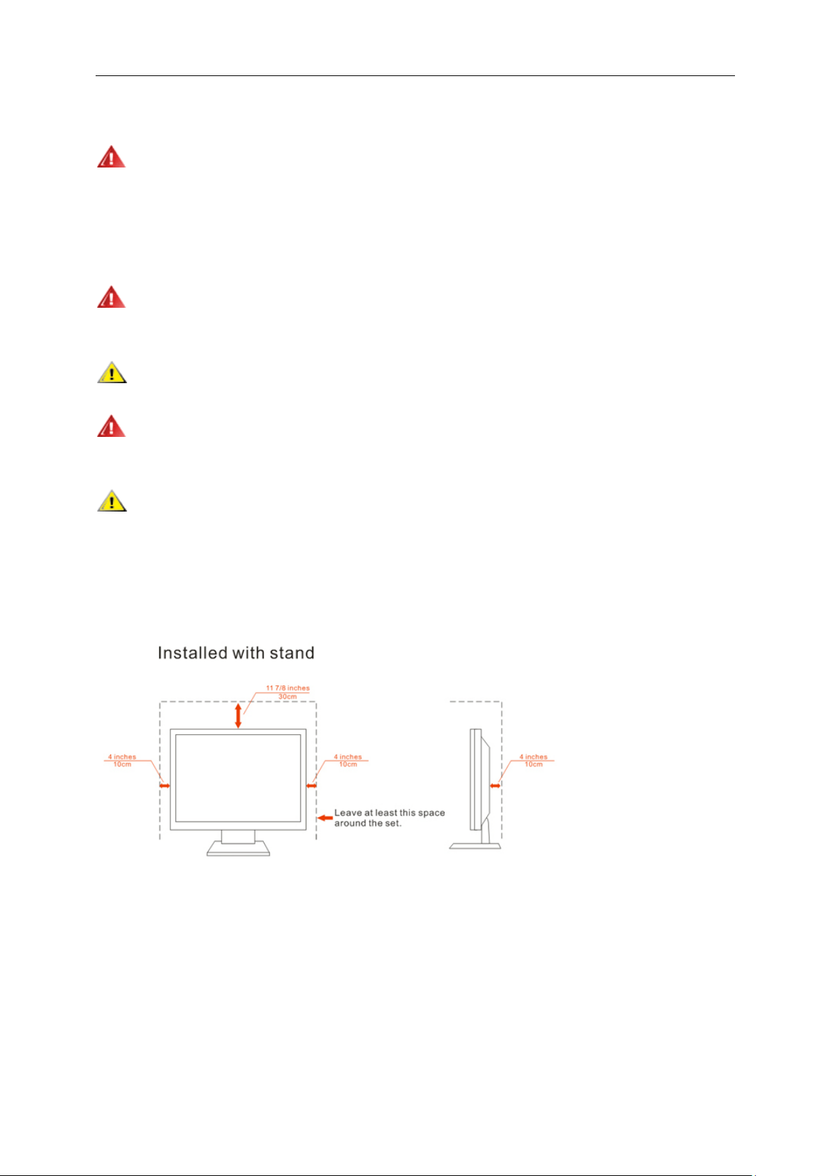
Leave some space around the monitor as shown below. Otherwise, air-circulation may be inadequate hence
overheating may cause a fire or damage to the monitor.
See below the recommended ventilation areas around the monitor when the monitor is installed on the wall or with
the stand:
Page 7
7
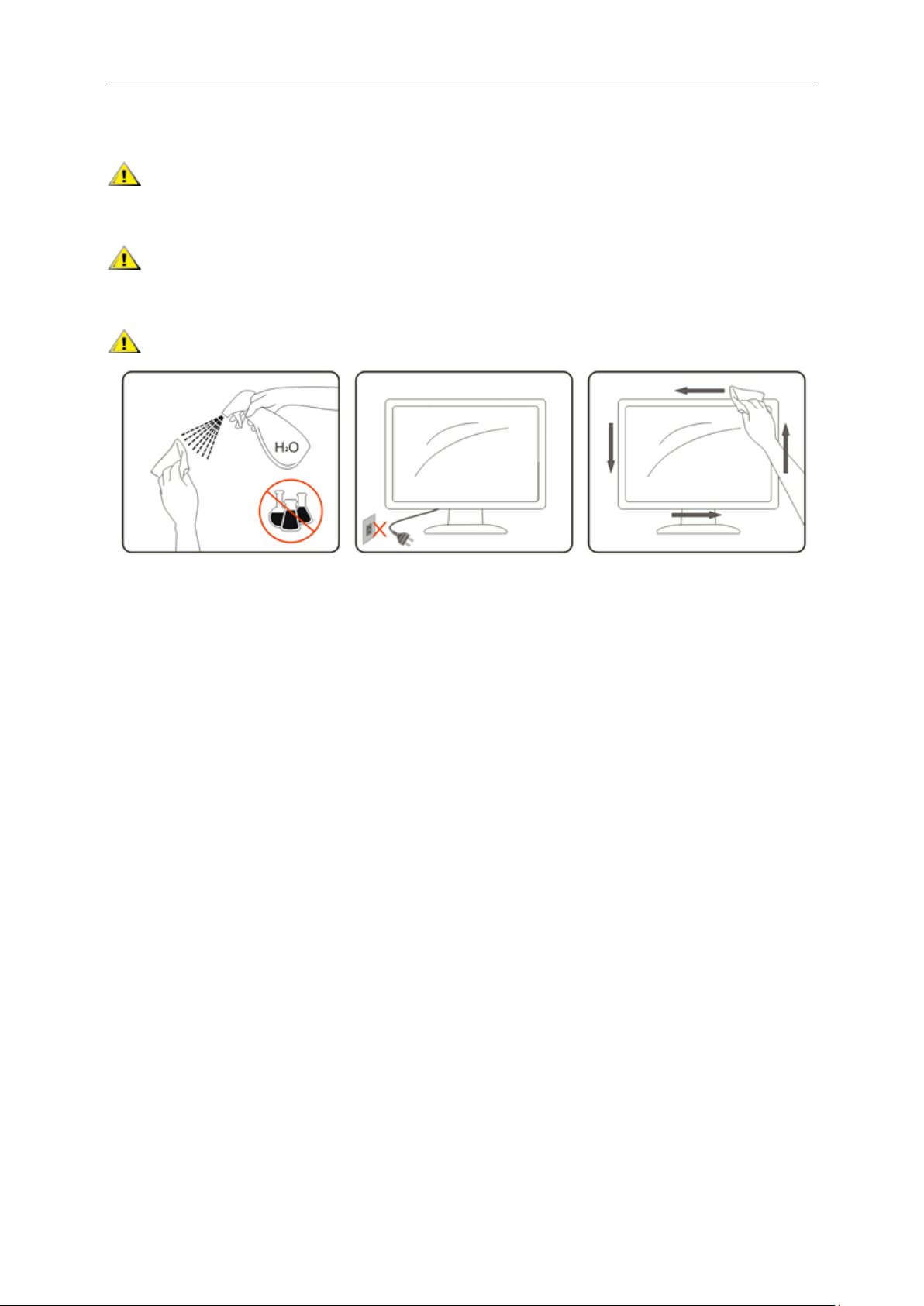
Cleaning
Clean the cabinet regularly with cloth. You can use soft-detergent to wipe out the stain, instead of
strong-detergent which will cauterize the product cabinet.
When cleaning, make sur e no deter g ent is l eak ed into the product. The cleaning cloth shoul d not be too roug h
as it will scratch the screen surface.
Please disconnect the power cord before cleaning the product.
Page 8

8
Other
If the product is emitting a strange smell, sound or smoke, disconnect the power plug IMMEDIATELY and
contact a Service Center.
Make sure that the ventilating openings are not blocked by a table or curtain.
Do not engage the LCD monitor in severe vibration or high impact conditions during operation.
Do not knock or drop the monitor during operation or transportation.
For display with glossy bezel the user should consider the placement of the display as the bezel may cause
disturbing reflections from surrounding light and bright surfaces.
Page 9
9
Setup
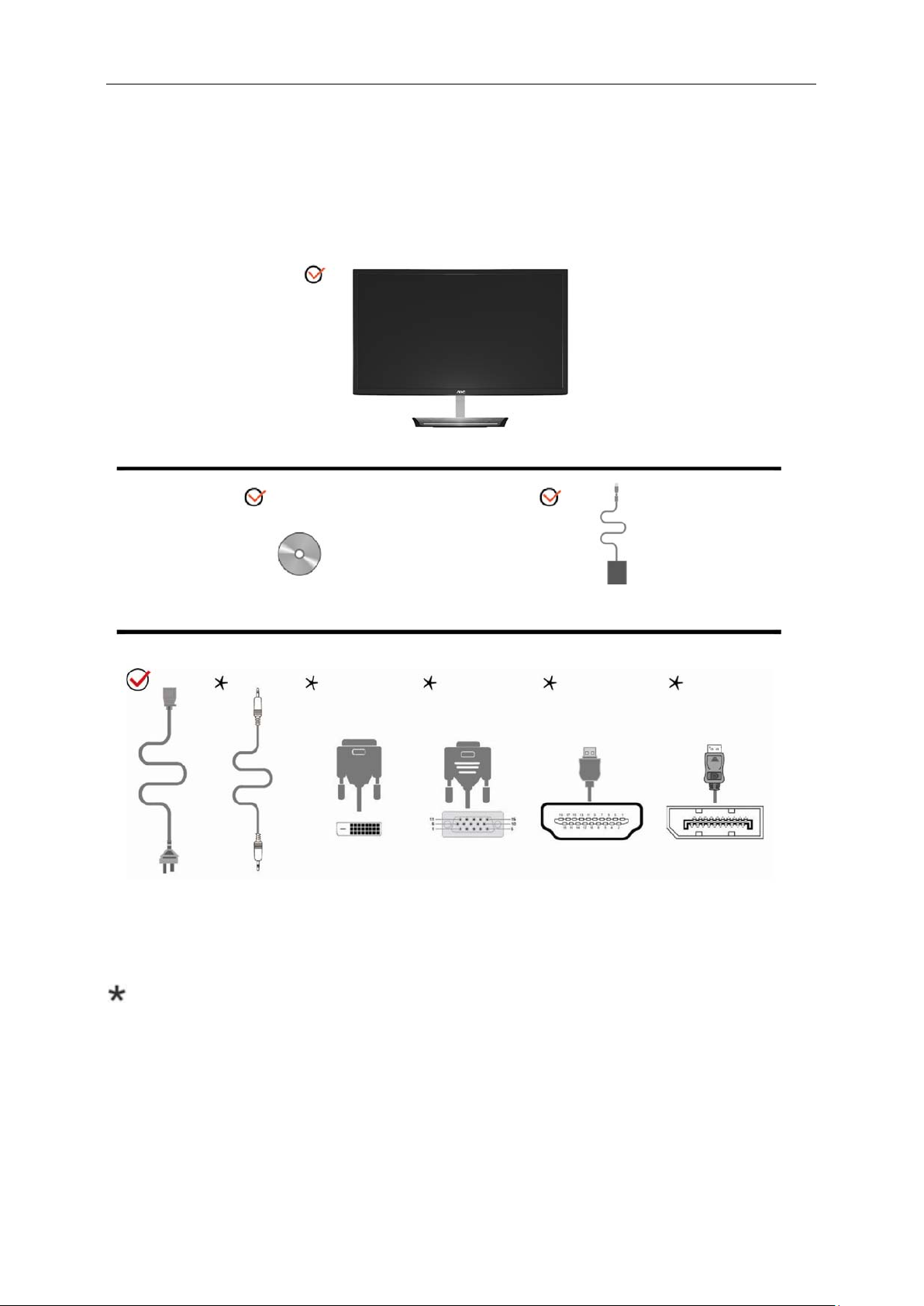
CD Manual Adapter
Power cable Audio cable DVI cable Analog Cable HDMI cable DP cable
Monitor
Contents in Box
Not all signal cables (Audio, Dual link DVI, Analog, DP, HDMI, MHL cables) will be provided for all countries
and regions. Please check with the local dealer or AOC branch office for confirmation.
Page 10
10
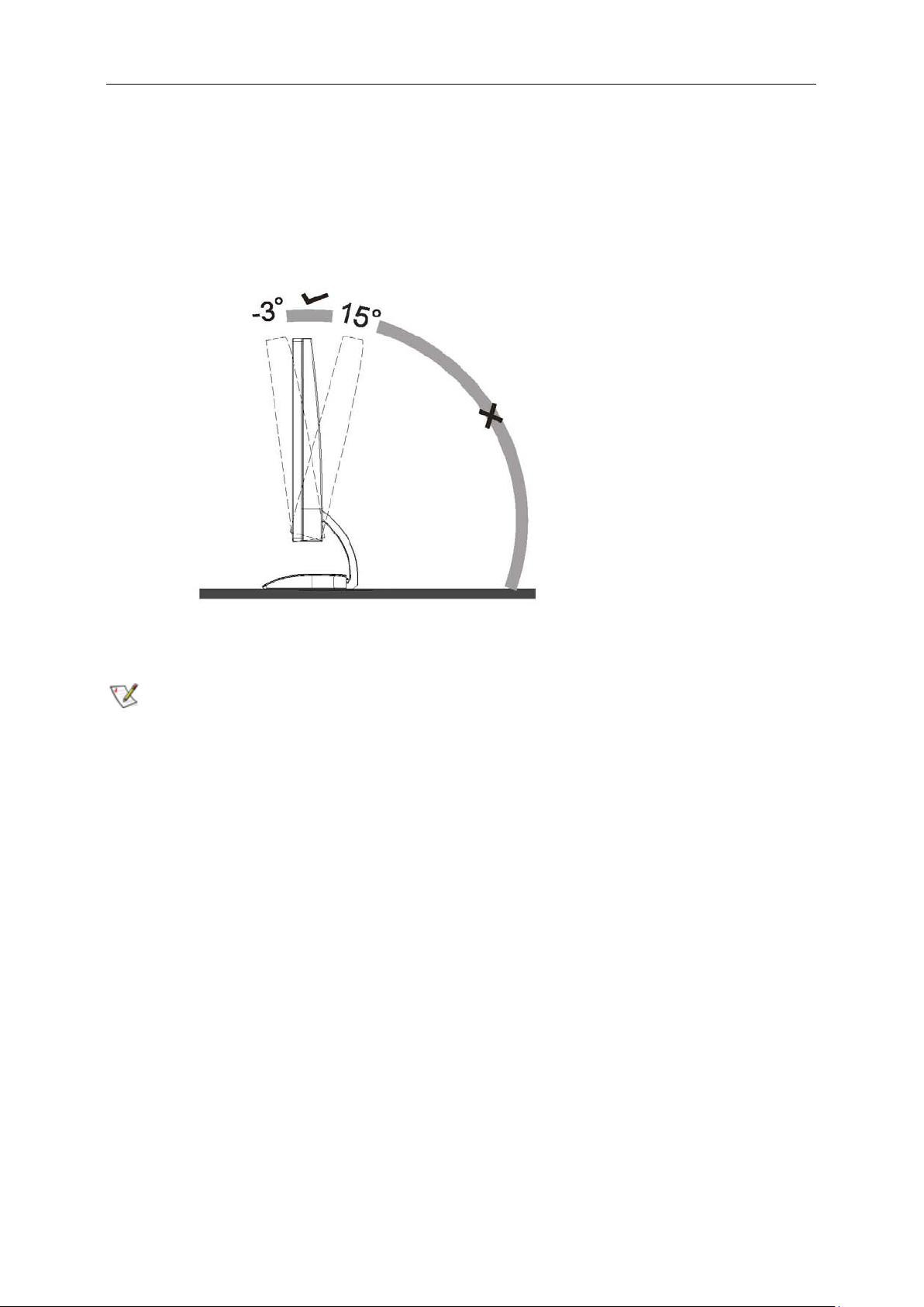
Adjusting Viewing Angle
For optimal viewing, it is recommended to look at the full face of the monitor, and then adjust the monitor's angle to
your own preference.
Hold the stand so you will not topple the monitor when you change the monitor's angle.
You are able to adjust the monitor's angle from -3° to 15 °.
NOTE:
Do not adjust the viewing angle over 15 degrees in order to avoid damage.
Page 11
11
Connecting the Monitor
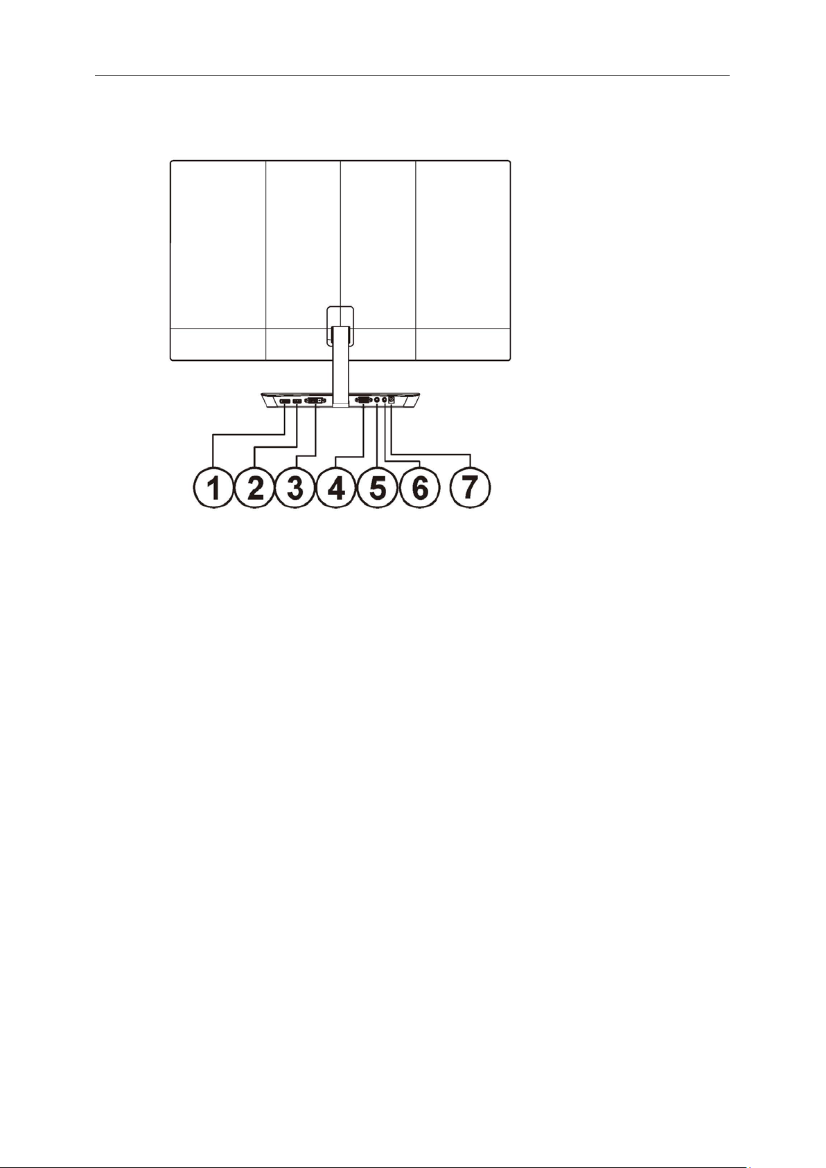
Cable Connections In Back of Monitor and Computer:
1 Display port
2 HDMI/MHL
3 DVI
4 Analog (D-Sub 15-Pin VGA cable)
5 AUDIO IN
6 Earphone out
7 Power
To protect equipment, always turn off the PC and LCD monitor before connecting.
1 Connect the adapter cable to the DC port on black of the monitor.
2 Connect one end of the 15-pin D-Sub cable to the back of the monitor and connect the other end to the
computer's D-Sub port.
3 Optional – (Requir es a v id eo c ard with DVI port) – Connect one end of the DVI cable to the back of the monitor
and connect the other end to the computer’s DVI port.
4 Optional – (Requires a video card with HDMI port) – Connect one end of the HDMI cable to the back of the
monitor and connect the other end to the computer’s HDMI port.
5 Optional – (Requires a video card with DP port) – Connect one end of the DP cable to the back of the monitor
and connect the other end to the computer’s DP port.
6 Turn on your monitor and computer.
If your monitor displays an image, installation is complete. If it does not display an image, please refer
Troubleshooting.
Page 12
12
Adjusting
Setting Optimal Resolution
Windows 8
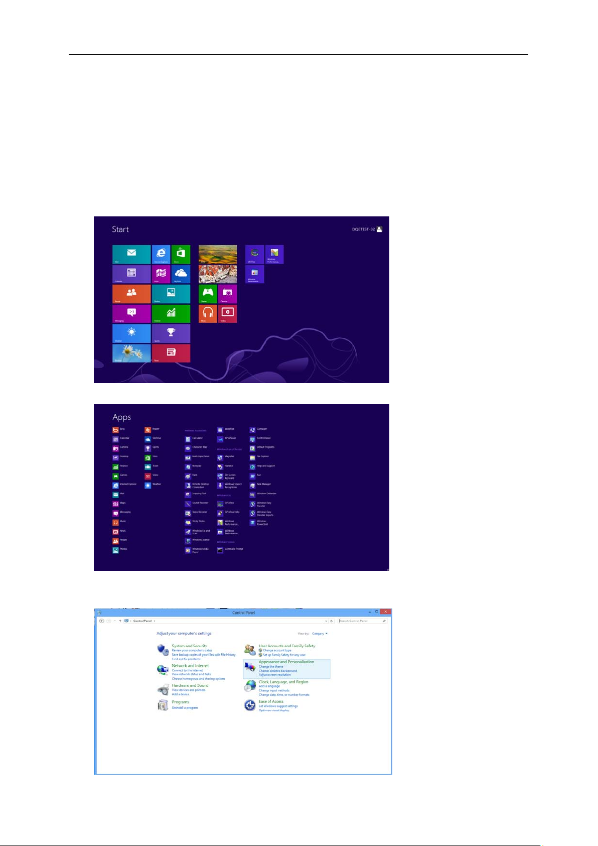
For Windows 8:
1. Right click and click All apps at the bottom-right of the screen.
2. Set the “View b y” to “Category”.
3. Click Appearance and Personalization.
Page 13
13
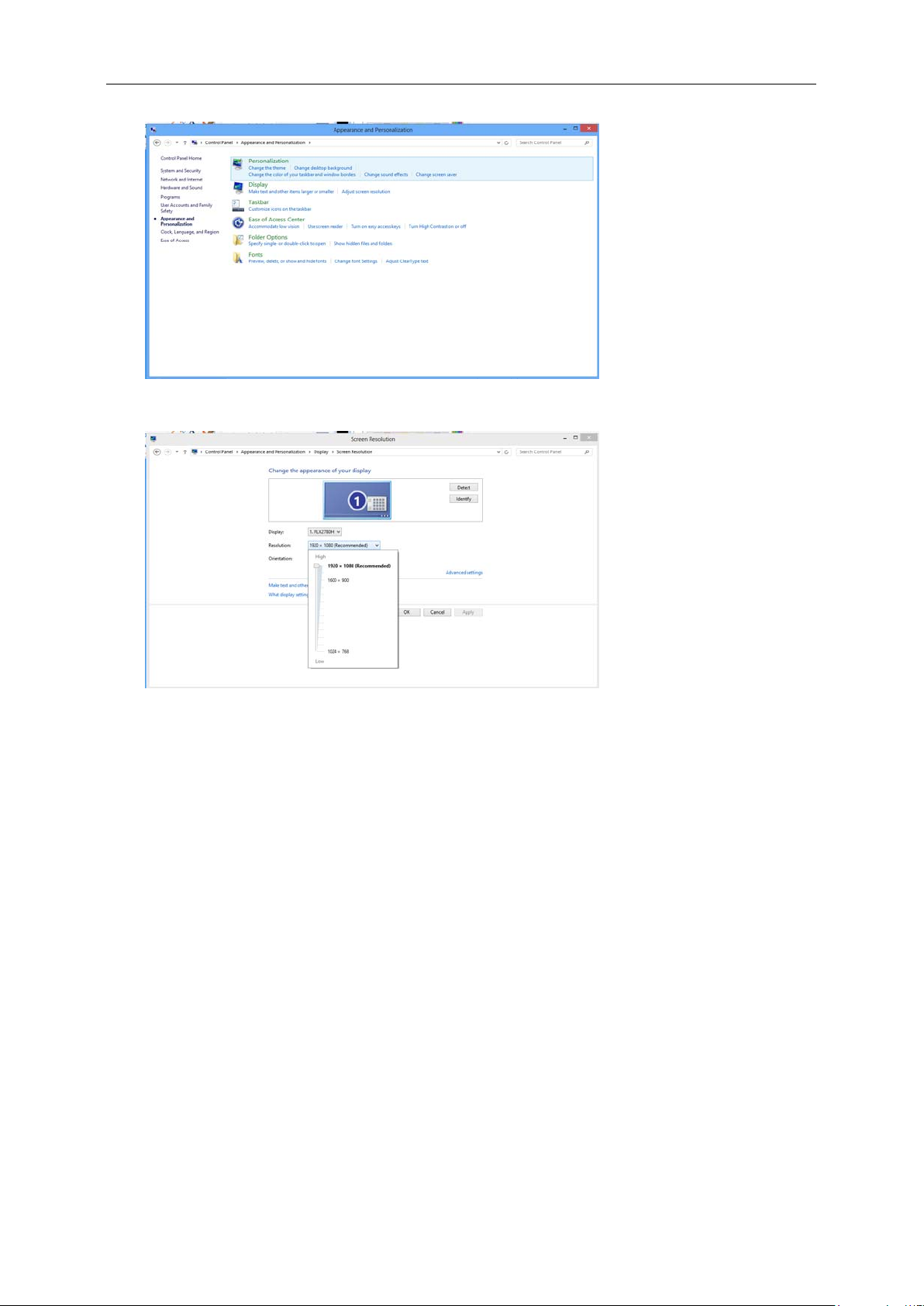
4. Click DISPLAY.
5. Set the resolution SLIDE-BAR to Optimal preset resolution.
Page 14
14
Windows 7
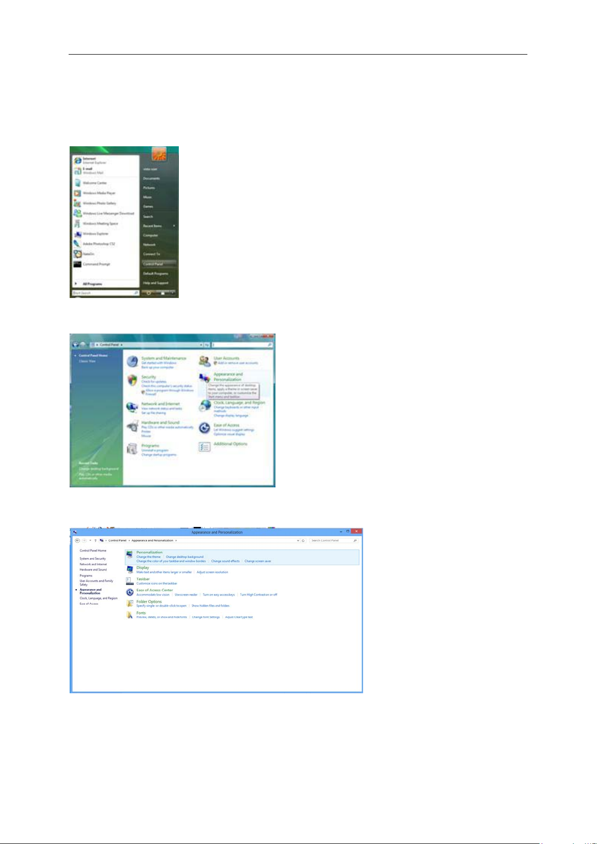
For Windows 7:
1. Click START.
2. Click CONTROL PANEL.
3. Click APPEARANCE.
4. Click DISPLAY
Page 15
15
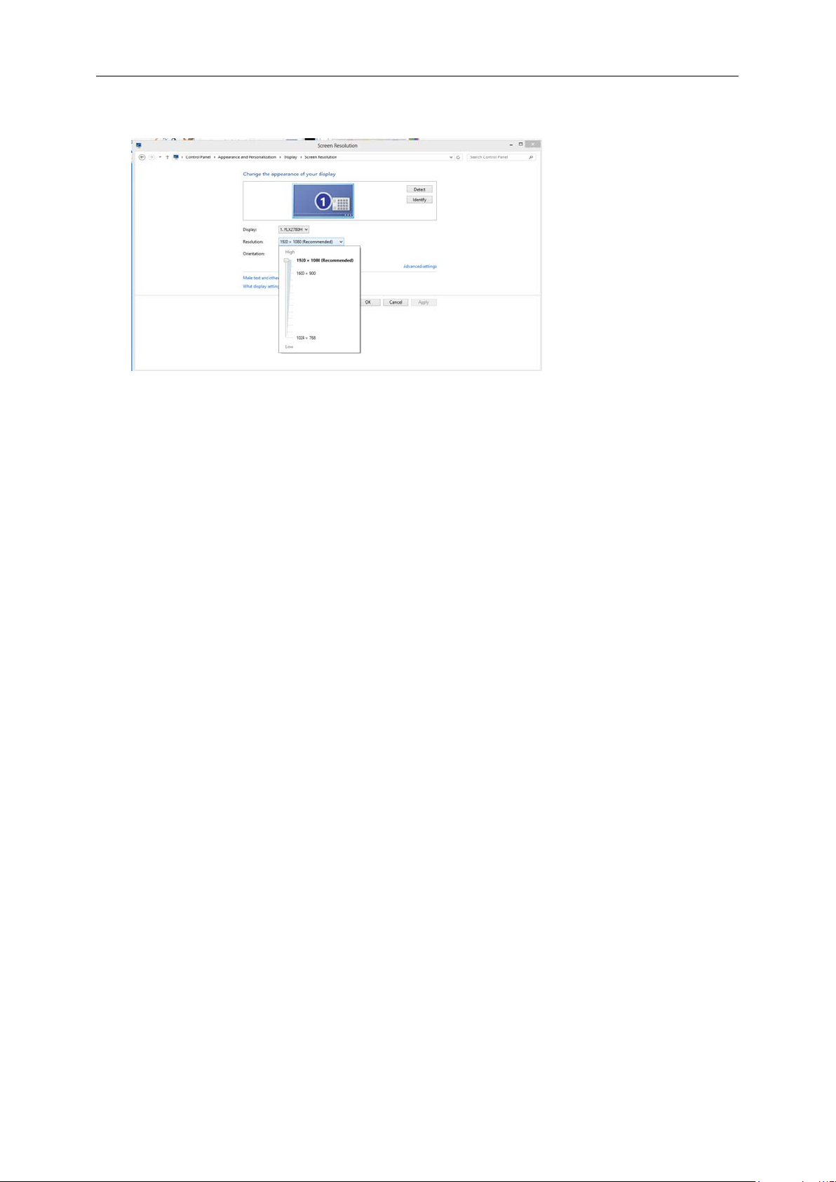
5. Set the resolution SLIDE-BAR to Optimal preset re sol uti on.
Page 16
16
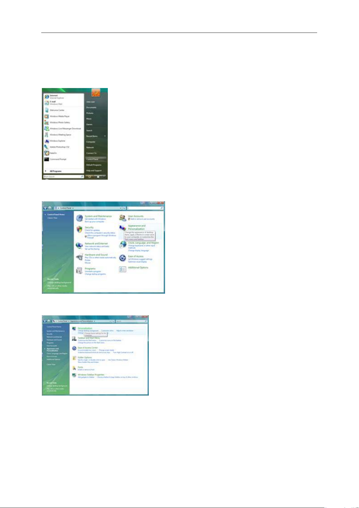
Windows Vista
For Windows Vista:
1. Click START.
2. Click CONTROL PANEL.
3. Click Appearance and Personalization.
4. Click Personalization
Page 17
17
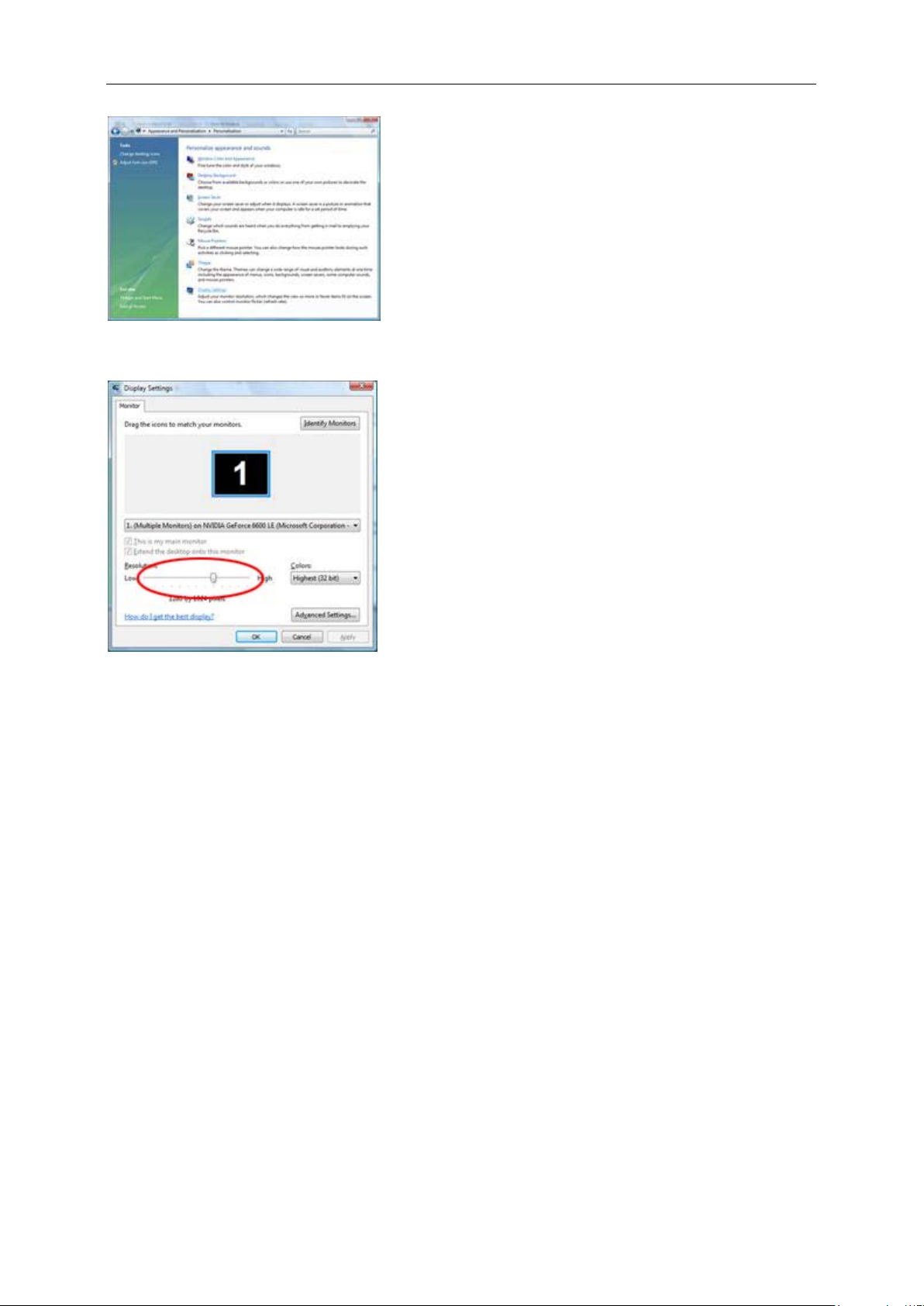
5. Click Display Settings.
6. Set the resolution SLIDE-BAR to
Optimal preset resolution.
Page 18
18
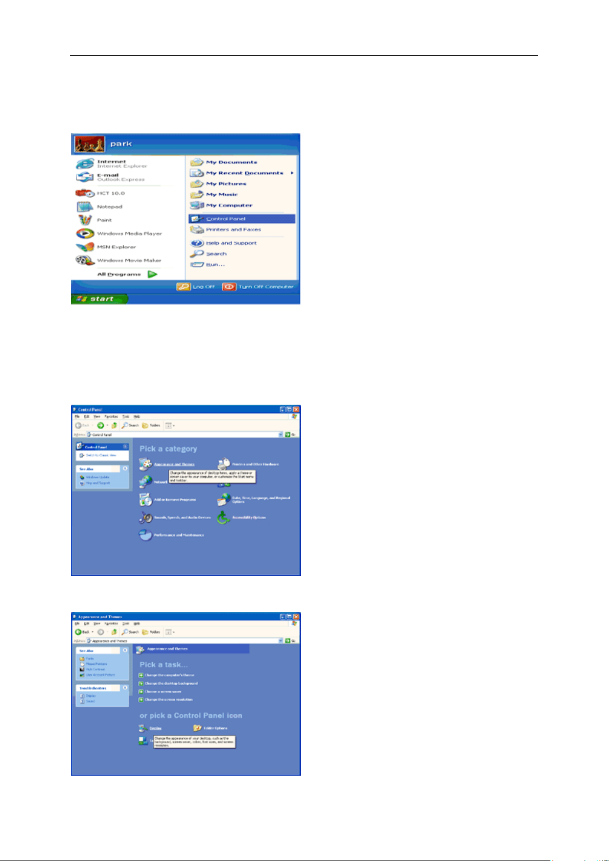
Windows XP
For Windows XP:
1 Click START.
2 Click SETTINGS.
3 Click CONTROL PANEL.
4 Click Appearance and Themes.
5 Double click DISPLAY.
Page 19
19
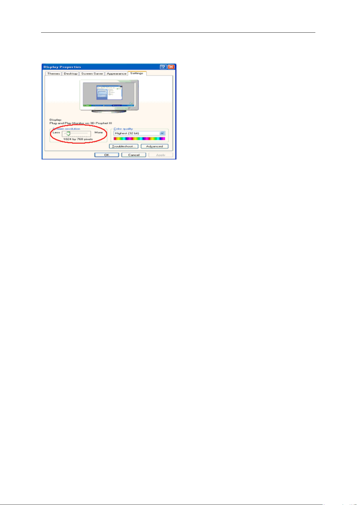
6 Click SETTINGS.
7 Set the resolution SLIDE-BAR to Optimal preset resolution.
Windows ME/2000
For Windows ME/2000:
1. Click START.
2. Click SETTINGS.
3. Click CONTROL PANEL.
4. Double click DISPLAY.
5. Click SETTINGS.
6. Set the resolution SLIDE-BAR to
Optimal preset resolution.
Page 20
20
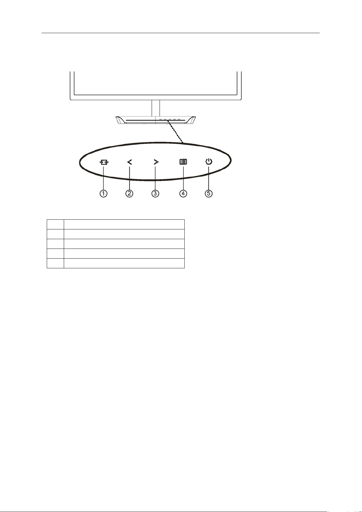
Hotkeys
1
Source/Auto/Exit
2
Clear Vision/<
3
Volume/>
4
Menu/Enter
5
Power
Menu/Enter
Press to display the OSD or confirm the selection.
Power
Press the Power button to turn on/off the monitor.
Volume/>
When there is no OSD, press Volume adjust volume.
Auto / Exit / Source hot key
When there is no OSD, press Auto/Source button continuously about 2 second to do auto configure. When the
OSD is closed, press Source b utton will be Source hot key function. Press Source b utto n co ntinuously to select the
input source showed in the message bar, press Menu/Enter button to change to the source selected.
Page 21

21
Clear Vision
1. When there is no OSD, Press the “<” button to activate Clear Vision.
2. Use the “<” or “>” buttons to select between weak, medium, strong, or off settings. Default setting is always
“off”.
3. Press and hold “<” button for 5 seconds to activate the Clear Vision Demo, and a mes sag e of “Clear Vision
Demo: on” will be display on the screen for a duration of 5 seconds. Press Menu or Exit button, the message
will disappear. Press and hold “<” button for 5 seconds again, Clear Vision Demo will be off.
Clear Vision function provides the best image viewing experience by converting low resolution and blurry images
into clear and vivid images.
Page 22

22
Using "MHL(Mobile High-Definition Link)"
1."MHL" (Mobile High-Definition Link)
This feature allows you to enjoy videos and photos (imported from a connected mobile device that supports MHL)
on the screenof the product.
To use the MHL function, you need an MHL-certified mobile device. You can check if your mobile device is
MHL certified on the device manufacturer's website. To find a list of MHL-certified de v ices, visit the official
MHL website (http://www.mhlconsortium.org).
To use the MHL function, the latest version of software must be installed on the mobile device.
On some mobile devices, the MHL function may not be available depending on the device's performance or
functionality.
Since the display size of the product is larger than those of mobile devices, the picture quality may degrade.
This product is officially M H L-certified. If you encounter any problem when using the MHL function, please
contact the manufacturer of the mobile device.
The picture quality may degrade when content (imported from the mobile device) with a low Resolution is
played on the product.
Using "MHL"
1. Connect the micro USB port on the mobile device to the [HDMI / MHL] port on the product using the MHL cable.
When the MHL cable is used, [HDMI / MHL] is the only port on this monitor that supports the MHL function.
Mobile device must be purchased separately.
2. Connect the AC pow er cord to the produ ct and a pow er outlet.
3. Press the source button
4. After about 3 seconds, the MHL screen will be displayed if MHL mode is active.
Remark: The indicated time "3 sec later" may vary depending on the mobile device.
When the mobile device is not connected or does not support MHL
If MHL mode is not act ivated e ven though the mo bile dev ice supp orts M H L, check if mobil e device M HL port is
MHL standard port otherwise an additional MHL-enabled adapter is required.
and switch to HDMI /MHL to activate MHL mode.
Page 23

23
OSD Setting
Basic and simple instruction on the control keys.
1. Press the MENU-button to activate the OSD window.
2. Press
press the MENU-button to activate it. If there is a sub-menu, press or to navigate through the
sub-menu functions.
3. Press or to change the settings of the selected function. Press AUTO to exit. If you want to
adjust any other function, repeat steps 2-3.
4. OSD Lock Function: To lock the OSD, pre ss and ho ld t he
press
while the monitor is off and then press power button to turn the monitor on.
Notes:
1. If the product has only one signal input, the item of "Input Select" is disabled.
2. If the product screen size is 4:3 or input signal resolution is native resolution, the item of "Image Ratio" is
disabled.
3. One of Clear vision, DCR, Color Boost, and Picture Boost functions is activated; the other three functions are
turned off accordingly.
or to navigate through the functions. Once the desired function is highlighted,
MENU-button while the monitor is off and then
power button to turn the monitor on. To un-lock the OSD - press and hold the MENU-button
Page 24

24
Luminance
1 Press MENU (Menu) to display menu.
2 Press or to select (Luminance), and press MENU to enter.
3 Press
or to select submenu.
Page 25

25
4 Press
or to adjust.
5 Press
AUTO to exit.
Contrast 0-100 Contrast from Digital-register.
Brightness 0-100 Backlight Adjustment
Eco mode
Gamma
DCR
Standard
Text
Internet
Game
Movie
Sports
Gamma1 Adjust to Gamma 1
Gamma2 Adjust to Gamma 2
Gamma3 Adjust to Gamma 3
Off Disable dynamic contrast ratio
On
Standard Mode
Text Mode
Internet Mode
Game Mode
Movie Mode
Sports Mode
Enable dynamic contrast ratio
Page 26

26
OverDrive
Weak
Medium
Strong
Off
Adjust the response time.
Page 27

27
Image Setup
1 Press MENU (Menu) to display menu.
2 Press
3 Press
or to select (Image Setup), and press MENU to enter.
or to select submenu.
Page 28

28
4 Press
or to adjust.
5 Press
AUTO to exit.
Clock 0-100 Adjust picture Clock to reduce Vertical-Line noise.
Phase 0-100 Adjust Picture Phase to reduce Horizontal-Line noise.
Sharpness 0-100 Adjust picture sharpness.
H.Position 0-100 Adjust the horizontal position of the picture.
V.Position 0-100 Adjust the vertical position of the picture.
Page 29

29
Color Setup
1 Press MENU (Menu) to display menu.
2 Press or to select (Color Setup), and press MENU to enter.
3 Press
or to select submenu.
Page 30

30
4 Press
or to adjust.
5 Press
AUTO to exit.
Warm Recall Warm Color Temperature from EEPROM.
Normal Recall Normal Color Temperature from EEPROM.
Color Temp.
DCB Mode
DCB Demo ON/OFF Disable or Enable Demo.
Red 0-100 Red gain from Digital-register.
Green 0-100 Green gain from Digital-register.
Cool Recall Cool Color Temperature from EEPROM.
sRGB Recall SRGB Color Temperature from EEPROM.
User Recall User Color Temperature from EEPROM
Full Enhance ON/OFF Disable or Enable Full Enhance Mode.
Nature Skin ON/OFF Disable or Enable Nature Skin Mode.
Green Field ON/OFF Disable or Enable Green Field Mode.
Sky-blue ON/OFF Disable or Enable Sky-blue Mode.
AutoDetect ON/OFF Disable or Enable AutoDetect Mode.
Blue 0-100 Blue gain from Digital-register.
Page 31

31
Picture Boost
1 Press MENU (Menu) to display menu.
2 Press or to select (Picture Boost), and press MENU to enter.
3 Press
or to select submenu.
Page 32

32
4 Press
or to adjust.
5 Press
AUTO to exit.
Bright Frame ON/OFF Enable/Disable Bright Frame
Frame Size 14-100 Adjust the Size of the Frame
Brightness 0-100 Brightness Adjustment for Enhance Area
Contrast 0-100 Contrast Adjustment for Enhance Area
H. position 0-100 Adjust the horizontal position of the Frame
V. position 0-100 Adjust the vertical position of the Frame
Page 33

33
OSD Setup
1 Press MENU (Menu) to display menu.
2 Press
3 Press
or to select (OSD Setup), and press MENU to enter.
or to select submenu.
Page 34

34
4 Press
or to adjust.
5 Press
AUTO to exit.
English, France , Spanish,
Portugues,German,
Language
Timeout 5-120 Adjust the OSD timeout.
H. Position 0-100
V. Position 0-100 Adjust the vertical position of the OSD.
Transparence 0-100 Adjust the OSD
Break
Reminder
Italian,Dutch,Swedish, Finnish,
Polish ,Czech, Russia,Korea,
TChina, SChina,Japanese.
ON/OFF
Select the OSD language
Adjust the horizontal position of the
OSD.
Break Reminder if the user continuely
work for mare than 1 hurs
Page 35

35
Extra
1 Press
MENU (Menu) to display menu.
2 Press
3 Press
or to select (Extra), and press MENU to enter.
or to select submenu.
Page 36

36
4 Press
or to adjust.
5 Press
AUTO to exit.
Auto Auto Detect input signal
D-SUB Select D-SUB signal source as input
Input Select
Auto Config.
Off Timer 0-24 hrs Select DC off time.
Image Ratio wide or 4:3 Select wide or 4:3 format for display
DDC/CI Yes / No Turn on or off DDC/CI Support.
Reset Yes / No Reset the menu to default.
DVI Select DVI signal source as input
HDMI/MHL Select HDMI/MHL signal Source as input
DP Select DP signal Source as input
Yes / No Auto adjust.the picture to default.
Page 37

37
Exit
1 Press
MENU (Menu) to display menu.
2 Press
3 Press
or to select (Exit), and press MENU to enter.
AUTO to exit.
Exit Exit the main OSD
Page 38

38
LED Indicator
Status LED Color
Full Power Mode Blue
Power Saving Orange
Page 39

39
Driver
Monitor Driver
Windows 8
1. Start Windows® 8
2. Right click and click All apps at the bottom-right of the screen.
3. Click on the “Control panel” icon
4. Set the “View by” to “Large icons” or “Small icons”.
Page 40

40
5. Click on the “Display” icon.
6. Click on the “Change display settings” button.
7. Click the
“Advanced Settings” button.
Page 41

41
8. Click the “Monitor” tab and then click the “Properties” button.
9. Click the “Driver” tab.
10. Open the “Update Driver Software-Generic PnP Monitor” window by clicking on “Update Driver... “ and
then click the "Browse my computer for driver software" button.
Page 42

42
11. Select "Let me pick from a list of device drivers on my computer".
12. Click the “Have Disk” button. C lick on the “Browse” button and navigate to the following directory:
X:\Driver\module name (where X is the drive letter designator for the CD-ROM drive).
13. Select the "xxx.inf" file and click the “Open” button. Click the “OK” button.
14. Select your monitor model and click the “Next” button. The files will be copied from the CD to your hard disk
drive.
15. Close all open windows and remove the CD.
16. Restart the system. The system will automatically select the maximum refresh rate and corresponding Color
Matching Profiles.
Page 43

43
Windows 7
1. Start Windows® 7
2. Click on the 'Start' button and then click on 'Control Panel'.
3. Click on the “Display” icon.
4. Click on the “Change display settings” button.
Page 44

44
5. Click the “Advanced Settings” button.
6. Click the “Monitor” tab and then click the “Properties” button.
7. Click the “Driver” tab.
Page 45

45
8. Open the "Update Driver Software-Generic PnP Monitor" window by clicking on “Update Driver... “ and
then click the "Browse my computer for driver software" button.
9. Select "Let me pick from a list of device drivers on my computer".
10. Click the “Have Disk” button. C lick on the “Browse” button and navigate to the following directory:
X:\Driver\module name (where X is the drive letter designator for the CD-ROM drive).
Page 46

46
11. Select the "xxx.inf" file and click the “Open” button. Click the “OK” button.
12. Select your monitor model and click the “Next” button. The files will be copied from the CD to your hard disk
drive.
13. Close all open windows and remove the CD.
14. Restart the system. The system will automatically select the maximum refresh rate and corresponding Color
Matching Profiles.
Page 47

47
Windows Vista
1. Click "Start" and "Control Panel". Then, double-cli ck on "Appearance and Personalization".
2. Click "Personalization" and then "Display Settings".
3. Click "Advanced Settings...".
Page 48

48
4. Click "Properties" in the "Monitor" tab. If the "Properties" button is deactivated, it means the configuration
for your monitor is completed. The monitor can be used as is.
If the message "Windows needs..." is displayed, as shown in the figure below, click "Continue".
5. Click "Update Driver..." in the "Driver" tab.
6. Check the "Browse my computer for driver software" checkbox and click "Let me pick from a list of
device drivers on my computer".
7. Click on the “Have disk...” button, then click on the “Browse...” button and then select the appropriate drive
F:\Driver (CD-ROM Drive).
8. Select your monitor model and click on the “Next” button.
9. Click "Close" → "Close" → "OK" → "OK" on the following screens displayed in sequence.
Page 49

49
Windows XP
1. Start Windows® XP
2. Click on the 'Start' button and then click on 'Control Panel'.
3. Select and click on the category ‘Appearance and T heme s’
4. Click on the 'Display' Item.
Page 50

50
5. Select the 'Settings' tab then click on the 'Advanced' button.
6. Select 'Monitor' tab
- If the 'Properties' button is inactive, it means your monitor is properly configured. Please stop installation.
- If the 'Properties' button is active, click on 'Properties' butt o n.
Please follow the steps below.
7. Click on the 'Driver' tab and then click on 'Update Driver...' button.
Page 51

51
8. Select the 'Install from a list or specific location [advanced]' radio button and then click on the 'Next' button.
9. Select the 'Don't Search. I will choose the driver to install' radio button. Then click on the 'Next' button.
10. Click on the 'Have disk...' button, then click on the 'Browse...' button and then select the appropriate drive F:
(CD-ROM Drive).
11. Click on the 'Open' button, then click the 'OK' button.
12. Select your monitor model and click on the 'Next' button.
- If you can see t he 'has not passed Windows® Logo t est ing to verify its compatibility with Windows® XP' message,
please click on the 'Continue Anyway' button.
13. Click on the 'Finish' button then the 'Close' button.
14. Click on the 'OK' button and then the 'OK' button again to close the Display Properties dialog box.
Page 52

52
Windows 2000
1. Start Windows® 2000.
2. Click on the 'Start' button, point to 'Settings', and then click on 'Control Panel'.
3. Double click on the 'Display' Icon.
4. Select the 'Settings' tab then click on 'Advanced...'.
5. Select 'Monitor'
- If the 'Properties' button is inactive, it means your monitor is properly configured. Please stop installation.
- If the 'Properties' button is active. Click on 'Properties' button. Please follow the steps given below.
6. Click on 'Driver' and then click on 'Update Driver...' then click on the 'Next' button.
7. Select 'Display a list of the known drivers for this device so that I can choose a specific driver', then
click on 'Next' and then click on 'Have disk...'.
8. Click on the 'Browse...' button then select the appropriate drive F: (CD-ROM Drive).
9. Click on the 'Open' button, then click on the 'OK' button.
10. Select your monitor model and click on the 'Next' button.
11. Click on the 'Finish' button then the 'Close' button.
If you can see the 'Digital Signature Not Found' window, click on the 'Yes' button.
Windows ME
1. Start Windows® Me
2. Click on the 'Start' button, point to 'Settings', and then click on 'Control Panel'.
3. Double click on the 'Display' Icon.
4. Select the 'Settings' tab then click on 'Advanced...'.
5. Select the 'Monitor' button, then click on 'Change...' button.
6. Select 'Specify the location of the driver (Advanced)' and click on the 'Next' button.
7. Select 'Display a list of all the drivers in a specific location, so you can choose the driver you want',
then click on 'Next' and then click on 'Have Disk...'.
8. Click on the 'Browse...' button, select the appropriate drive F: (CD-ROM Drive) then click on the 'OK' button.
9. Click on the 'OK' button, select your monitor model and click on the 'Next' button.
10. Click on 'Finish' button then the 'Close' button.
Page 53

53
i-Menu
Welcome to “ i-Menu” software by AOC. i-Menu makes it easy to adjust your monitor display setting by using on
screen menus instead of the OSD button on the monitor. To complete installation, please follow the installation
guide. The software Supported operating systems: Windows 8, Windows 7, Windows Vista, Windows XP.
Page 54

54
e-Saver
Welcome to use AOC e-Saver monitor power management software! The AOC e-Saver features Smart Shutdown
functions for your monitors, allows your monitor to timely shu tdown when PC unit is at any status (On, Off, Slee p or
Screen Saver); the actual shutdown time depends on your preferences (see example below).
Please click on "driver/e-Saver/setup.exe" to start installing the e-Saver software, follow the install wizard to
complete software installation.
Under each of the four PC statuses, you may choose the desired time (in minutes) from the pull-down menu for
your monitor to automatically shutdown. The example below illustrated:
1) The monitor will never shutdown when the PC is powered on.
2) The monitor will automatically shutdown 5 minutes after the PC is powered off.
3) The monitor will automatically shutdown 10 minutes after the PC is in sleep/stand-by mode.
4) The monitor will automatically shutdown 20 minutes after the screen saver appears.
You can click “RESET” to set the e-Saver to its default settings like below.
Page 55

55
Screen+
Welcome to "Screen+" software by AOC. Screen+ software is a desktop screen splitting tool; it splits the desktop
into different panels, and each panel displays a different window. You only need to drag the window to a
corresponding panel when you want to access it. It supports multiple monitor display to make your task easier.
Please follow the inst alla tion s oftw are to in sta ll it . The software Supported opera ting sy stems: Windows 8, Windows
7, Windows Vista, Windows XP.
Page 56

56
Troubleshoot
Problem & Question
Power LED Is Not ON
No images on the screen
Possible Solutions
Make sure the power butt on is ON and the Pow er C ord is pro perly conne cted
to a grounded power outlet and to the monitor.
Is the power cord connected properly?
Check the power cord connection and power supply.
Is the cable connected correctly?
(Connected using the D-s ub c able)
Check the DB-15 cable connection.
(Connected using the DVI cable)
Check the DVI cable connection.
* DVI input is not available on every model.
If the power is on, reboot the computer t o see the initial screen (the login
screen), which can be seen.
If the initial screen (the login screen) appears, boot the computer in the
applicable mode (the safe mode for Window s ME/2000) and t hen chan ge
the frequency of the video card.
(Refer to the Setting the Optimal Resolution)
If the initial screen (the login screen) does not appear, contact the
Service Center or your dealer.
Can you see "Input Not Supported" on the screen?
You can see this message when the signal from the video card exceeds
the maximum resolution and frequency that the monitor can handle
properly.
Adjust the maximum resolution and frequency that the monitor can
handle properly.
Make sure the AOC Monitor Drivers are installed.
Picture Is Fuzzy & Has
Ghosting Shadowing Problem
Picture Bounces, Flickers Or
Wave Pattern Appears In The
Picture
Adjust the Contrast and Brightness Controls.
Press to auto adjust.
Make sure you are not using an extension cable or switch box. We
recommend plugging the monitor directly to the video card output connector
on the back.
Move electrical devices that may cause electrical interference as far away
from the monitor as possible.
Use the maximum refresh rate your monitor is capable of at the resolution
you are using.
Page 57

57
Monitor Is Stuck In Active
Off-Mode"
The Computer Power Switch should be in the ON position.
The Computer Video Card should be snugly fitted in its slot.
Make sure the monitor's video cable is properly connected to the computer.
Inspect the monitor's video cable and make sure no pin is bent.
Make sure your computer is operational by hitting the CAPS LOCK key on
the keyboard while observing the CAPS LOCK LED. The LED should either
turn ON or OFF after hitting the CAPS LOCK key.
Missing one of the primary
colors (RED, GREEN, or
BLUE)
Screen image is not centered
or sized properly
Picture has color defects
(white does not look white)
Horizontal or vertical
disturbances on the screen
Inspect the monitor's video cable and make sure that no pin is damaged.
Make sure the monitor's video cable is properly connected to the computer.
Adjust H-Position and V-Position or press hot-key (AUTO).
Adjust RGB color or select desired color temperature.
Use Windows 95/98/2000/ME shut-down mode to adjust CLOCK and
PHASE.
Press to auto-adjust.
Page 58

58
Specification
General Specification
Model name C2783FQ
Driving system TFT Color LCD
Viewable Image Size 68.6cm diagonal
Panel
Others
Environmental
Pixel pitch 0.3114(H)mm x 0.3114(V)mm
Video R, G, B Analog Interface & HDMI Interface
Separate Sync. H/V TTL
Display Color 16.7M Colors
Pixel Clock 148.5 MHz
Horizontal scan range 30~83KHz
Horizontal scan
Size(Maximum)
Vertical sc an range
Vertical sca n Size(Maximum) 336.31 mm
Optimal preset resolution 1920×1080@60Hz
Plug & Play VESA DDC2B/CI
Input Connector VGA/ DVI/HDMI(MHL)/DP
Input Video Signal
Power Source 20VDC, 3.25A
Power Consumption
Off timer 0-24 hrs
Temperature:
Operating 0° to 40°C
Non-Operating -20° to 60°C
Humidity:
Operating 20% to 90% (non-condensing)
Non-Operating 15% to 90% (non-condensing)
Altitude:
Operating 0~ 5000m(0~ 16404 ft)
Non-Operating 0~ 12192m (0~ 40000 ft )
597.89 mm
50Hz ~ 76Hz
Analog: 0.7Vp-p(standard), 75 OHM, Positive, TMDS
Digital: DVI, HDMI(MHL),DP
Typical (Brightness = 90,Contrast = 50) 38W
(Brightness = 100,Contrast = 100) 45W
Power saving ≤0.5W
Page 59

59
Preset Display Modes
Standard
Resolution
H. Frequency (kHz)
V. Frequency (Hz)
75
75
60
60
VGA
VGA
VGA
VGA
DOS MODE 720x400@70Hz 31.469 70.087
SVGA
SVGA
SVGA
SVGA
MAC MODE 832x624@75Hz 49.725 74.551
XGA
XGA
XGA
SXGA
SXGA
WXGA+
WSXGA
FHD
HD
HD 1280x720@60HZ
640x480@60Hz
640x480@67Hz
640x480@72Hz
640x480@75Hz
800x600@56Hz
800x600@60Hz
800x600@72Hz
800x600@75Hz
1024x768@60Hz
1024x768@70Hz
1024x768@75Hz
1280x1024@60Hz
1280x1024@75Hz
1440x900@60Hz
1680x1050@60Hz
1920x1080@60Hz
1280x960@60HZ
31.469
35 66.667
37.861
37.5
35.156
37.879
48.077
46.875
48.363
56.476
60.023
63.981
79.976
55.935
64.674
67.5
60
44.772
59.94
72.809
56.25
60.317
72.188
60.004
70.069
75.029
60.02
75.025
59.887
59.954
59.885
Page 60

60
Pin Assignments
15-Pin Color Display Signal Cable
Pin No. Signal Name Pin No. Signal Name
1 Video-Red 9 +5V
2 Video-Green 10 Ground
3 Video-Blue 11 N.C.
4 N.C. 12 DDC-Serial data
5 Detect Cable 13 H-sync
6 GND-R 14 V-sync
7 GND-G 15 DDC-Serial clock
8 GND-B
24-Pin Color Display Signal Cable
Pin No. Signal Name Pin No. Signal Name
1
2 TMDS data 2+ 14 +5V Power
3 TMDS data 2/4 Shield 15 Ground (for+5V)
4
5
6 DDC Clock 18 TMDS data 0+
7 DDC Data 19 TMDS data 0/5 Shield
8 N.C. 20
9
10 TMDS data 1+ 22 TMDS Clock Shield
11 TMDS data 1/3 Shield 23 TMDS Clock +
12
TMDS data 2-
TMDS data 4-
TMDS data 4+
TMDS data 1-
TMDS data 3-
13
16 Hot Plug Detect
17
21
24
TMDS data 3+
TMDS data 0-
TMDS data 5-
TMDS data 5+
TMDS Clock -
Page 61

61
19-Pin Color Display Signal Cable
Pin No. Signal Name Pin No. Signal Name
1 TMDS Data 2+ 11 TMDS Clock Shield
2 TMDS Data 2 Shield 12 TMDS Clock
3 TMDS Data 2 13 CEC
4 TMDS Data 1+ 14 Reserved (N.C. on device
5 TMDS Data 1Shield 15 SCL
6 TMDS Data 1 16 SDA
7 TMDS Data 0+ 17 DDC/CEC Ground
8 TMDS Data 0 Shield 18 +5V Power
9 TMDS Data 0 19 Hot Plug Detect
10 TMDS Clock +
20-Pin Color Display Signal Cable
Pin No. Signal Name Pin No. Signal Name
1
2
3
4
5
6
7
8
9
10
ML_Lane 3 (n)
GND
ML_Lane 3 (p)
ML_Lane 2 (n)
GND
ML_Lane 2 (p)
ML_Lane 1 (n)
GND
ML_Lane 1 (p)
ML_Lane 0 (n)
11
12
13
14
15
16
17
18
19
20
GND
ML_Lane 0 (p)
CONFIG1
CONFIG2
AUX_CH(p)
GND
AUX_CH(n)
Hot Plug Detect
Return DP_PWR
DP_PWR
Page 62

62
Plug and Play
Plug & Play DDC2B Feature
This monitor is equipped with VESA DDC2B capabilities according to the VESA DDC STANDARD. It allows the
monitor to inform the host system of its identity and, depending on the level of DDC used, communicate additional
information about its display capabilities.
The DDC2B is a bi-directional data c hannel ba sed on the I 2C pr otocol. T he host can req ue st ED ID informat ion over
the DDC2B channel.
Page 63

63
Regulation
FCC Notice
FCC Class B Radio Frequency Interference Statement WARNING: (FOR FCC CERTIFIED MODELS)
NOTE: This equipment has been tested and found to comply with the limits for a Class B digital device, pursuant to
Part 15 of the FCC Rules. These limits are designed to provide reasonable protection against harmful interference
in a residential installation. This equipment generates, uses and can radiate radio frequency energy, and if not
installed and used in accordance with the instructions, may cause harmful interference to radio communications.
However, there is no guarantee that interfere nce will not occ ur in a partic ular in st allation. If this equipment does
cause harmful interference to radio or television reception, which can be determined by turning the equipment off
and on, the user is encouraged to try to correct the interference by one or more of the following measures:
Reorient or relocate the receiving antenna.
Increase the separation between the equipment and receiver.
Connect the equipment into an outlet on a circuit different from that to which the receiver is connected.
Consult the dealer or an experienced radio/TV technician for help.
NOTICE:
The changes or modifications not expressly approved by the party responsible f or co mpl ian ce co uld v oid th e user's
authority to operate the equipment.
Shielded interface cables and AC power cord, if any, must be used in order to comply with the emission limits.
The manufacturer is not responsible for any radio or TV interference caused by unauthorized modification to this
equipment. It is the res pon sib il itie s of the user to correct such interference. It is the responsibility of the user to
correct such interference.
Page 64

64
WEEE Declaration
Disposal of Waste Equipment by Users in Private Household in the European Union.
This symbol on the product or on its packaging indicates that this product must not be disposed of with your other
household waste. Instead, it is your responsibility to dispose of your waste equipment by handing it over to a
designated collection point for the recycling of waste electrical and electronic equipment. The separate collection
and recycling of your waste equipment at the time of disposal will help to conserve natural resources and ensure
that it is recycled in a manner that protects human health and the environment. For more information about where
you can drop off your waste equipment for recycling, please contact your local city office, your household waste
disposal service or the shop where you purchased the product.
WEEE Declaration for India
This symbol on the product or on its packaging indicates that this product must not be disposed of with your other
household waste. Instead it is your responsibility to dispose of your waste equipment by handing it over to a
designated collection point for the recycling of waste electrical and electronic equipment. The separate collection
and recycling of your waste equipment at the time of disposal will help to conserve natural resources and ensure
that it is recycled in a manner that protects human health and the environment.
For more information about where you can drop off your waste equipment for recycling in India, please visit the
below web link.
www.aocindia.com/ewaste.php.
RoHS Declaration for India
his product complies with all implemented RoH S type regulations worldwide, including but not limited to, EU,
Korea, Japan, US States (e.g. California), Ukraine, Serbia, Turkey, Vietnam and India.
We continue to monitor, influence and develop our processes to comply with upcoming proposed RoHS type
regulations, including but not limite d to, Braz il, Argentina, Canada.
Restriction on Hazardous Substances statement (India)
This product complies with the “India E-waste Rule 2011” and prohibits use of lead, mercury, hexavalent
chromium, polybrominated bipheny ls or polybr om inat ed diph eny l ether s in concentrations exceeding 0.1
weight % and 0.01 weight % for cadmium, except for the exemptions set in Schedule 2 of the Rule.
 Loading...