

Page 1
19" LCD Color Monitor I-INC AH191D
Service
Service
Service
Horizontal Frequency
31-80 kHz
TABLE OF CONTENTS
Description Page Description Page
Table Of Contents.......…….................……..........…........1
Revision List.…........................………................……......2
Important Safety Notice.………….…...............……......3
1. Monitor Specification.................................………........4
2.LCD Monitor Description…………………………….......5
3. Operation Instruction………….........……………...........7
3.1 General Instructions.....................................…...........7
3.2 Control Button…………………………………………...7
3.3 Adjusting the Picture...........................…............9
4. Input/Output Specification............……………............14
4.1 Input Signal Connector............………….................14
4.2 Factory Preset Display Modes..................................15
4.3 Panel Specification.....………………........................16
5.Block Diagram…….…................……..…..............19
5.1Software Flow Chart…………………...............19
5.2 Electrical Block Diagram………....………..………....21
ANY PERSON ATTEMPTING TO SERVICE THIS CHASSIS MUST FAMILIARIZE HIMSELF WITH THE CHASSIS
AND BE AWARE OF THE NECESSARY SAFETY PRECAUTIONS TO BE USED WHEN SERVICING ELECTRONIC
EQUIPMENT CONTAINING HIGH VOLTAGES.
CAUTION: USE A SEPARATE ISOLATION TRANSFOMER FOR THIS UNIT WHEN SERVICING
http://www.wjel.net
SAFETY NOTICE
6. Schematic…………………….…..............................23
6.1 Main Board…………..............................................23
6.2 Power Board....……………....................................28
6.3 Key Board ……………………………..…………….30
6.4 Audio Board....……...............................................31
7. PCB Layout..………….......................................32
7.1. Main Board………........................................32
7.2 Power Board….......................................34
7.3 Audio Board....…….......................................36
7.4 Keypad Board……….............................................36
8. Maintainability………...............................................37
8.1. Equipments and Tools Requirement.....................37
8.2. Trouble Shooting…………....................................38
9. White-Balance, Luminance adjustment...................44
10.Monitor Exploded View……..………………............45
11. BOM List....…….....................................................46
1
Page 2
19" LCD Color Monitor I-INC AH191D
Revision List
Revision Date Revision History TPV Model
A00 Nov-02-2006 Initial release T96HM6DTWEHZAE
http://www.wjel.net
2
Page 3

19" LCD Color Monitor I-INC AH191D
Important Safety Notice
Proper service and repair is important to the safe, reliable operation of all AOC Company Equipment. The service
procedures recommended by AOC and described in this service manual are effective methods of performing service
operations. Some of these service operations require the use of tools specially designed for the purpose. The special
tools should be used when and as recommended.
It is important to note that this manual contains various CAUTIONS and NOTICES which should be carefully read in
order to minimize the risk of personal injury to service personnel. The possibility exists that improper service methods
may damage the equipment. It is also important to understand that these CAUTIONS and NOTICES ARE NOT
EXHAUSTIVE. AOC could not possibly know, evaluate and advise the service trade of all conceivable ways in which
service might be done or of the possible hazardous consequences of each way. Consequently, AOC has not undertaken
any such broad evaluation. Accordingly, a servicer who uses a service procedure or tool which is not recommended by
AOC must first satisfy himself thoroughly that neither his safety nor the safe operation of the equipment will be
jeopardized by the service method selected.
Hereafter throughout this manual, AOC Company will be referred to as AOC.
WARNING
Use of substitute replacement parts, which do not have the same, specified safety characteristics may create shock, fire,
or other hazards.
Under no circumstances should the original design be modified or altered without written permission from AOC. AOC
assumes no liability, express or implied, arising out of any unauthorized modification of design.
Servicer assumes all liability.
FOR PRODUCTS CONTAINING LASER:
DANGER-Invisible laser radiation when open AVOID DIRECT EXPOSURE TO BEAM.
CAUTION-Use of controls or adjustments or performance of procedures other than those specified herein may result in
hazardous radiation exposure.
CAUTION -The use of optical instruments with this product will increase eye hazard.
TO ENSURE THE CONTINUED RELIABILITY OF THIS PRODUCT, USE ONLY ORIGINAL MANUFACTURER'S
REPLACEMENT PARTS, WHICH ARE LISTED WITH THEIR PART NUMBERS IN THE PARTS LIST SECTION OF
THIS SERVICE MANUAL.
Take care during handling the LCD module with backlight unit
-Must mount the module using mounting holes arranged in four corners.
-Do not press on the panel, edge of the frame strongly or electric shock as this will result in damage to the screen.
-Do not scratch or press on the panel with any sharp objects, such as pencil or pen as this may result in damage to the
panel.
-Protect the module from the ESD as it may damage the electronic circuit (C-MOS).
-Make certain that treatment person’s body is grounded through wristband.
-Do not leave the module in high temperature and in areas of high humidity for a long time.
-Avoid contact with water as it may a short circuit within the module.
-If the surface of panel becomes dirty, please wipe it off with a soft material. (Cleaning with a dirty or rough cloth may
damage the panel.)
http://www.wjel.net
3
Page 4
19" LCD Color Monitor I-INC AH191D
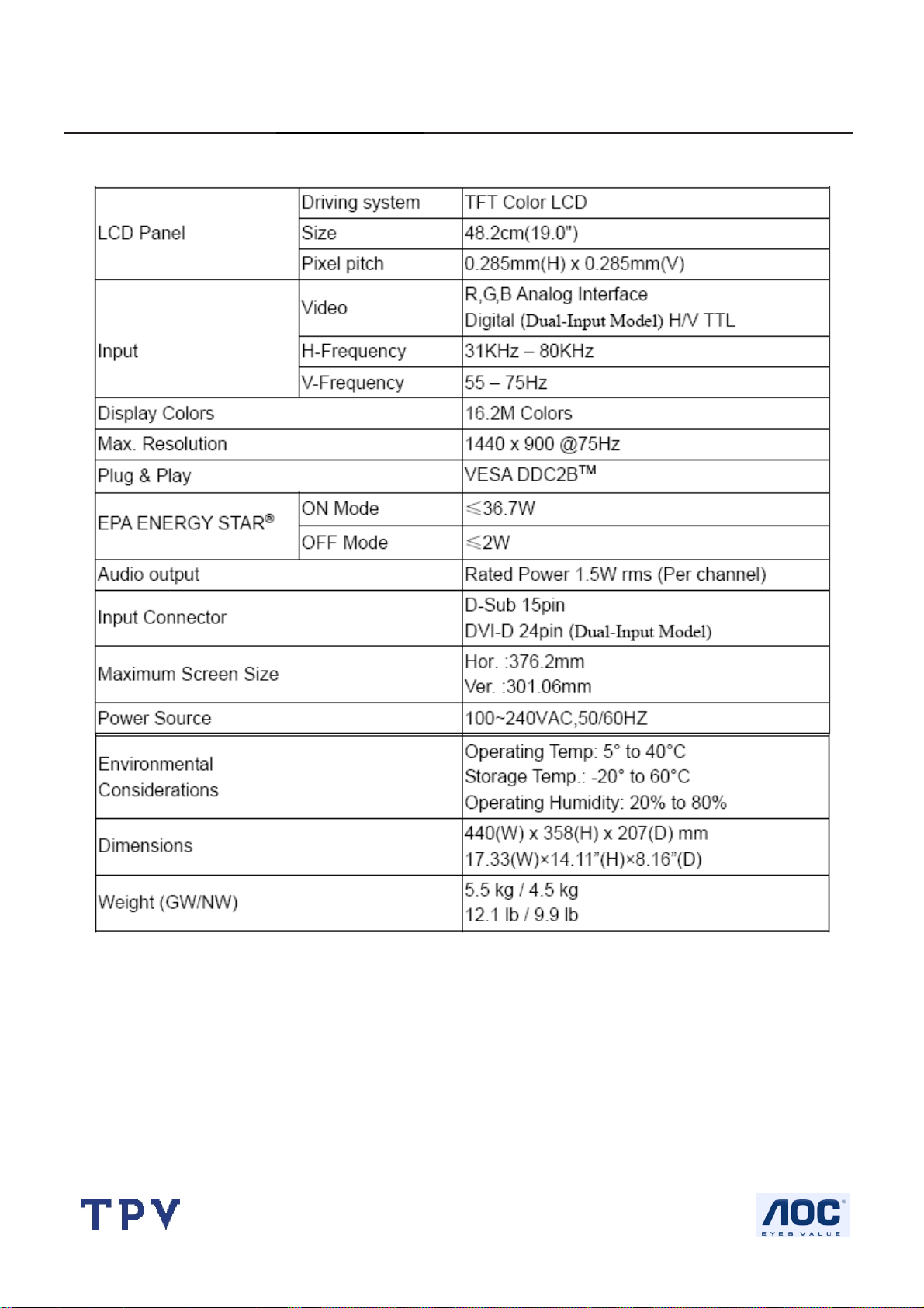
1. Monitor Specifications
http://www.wjel.net
4
Page 5
19" LCD Color Monitor I-INC AH191D
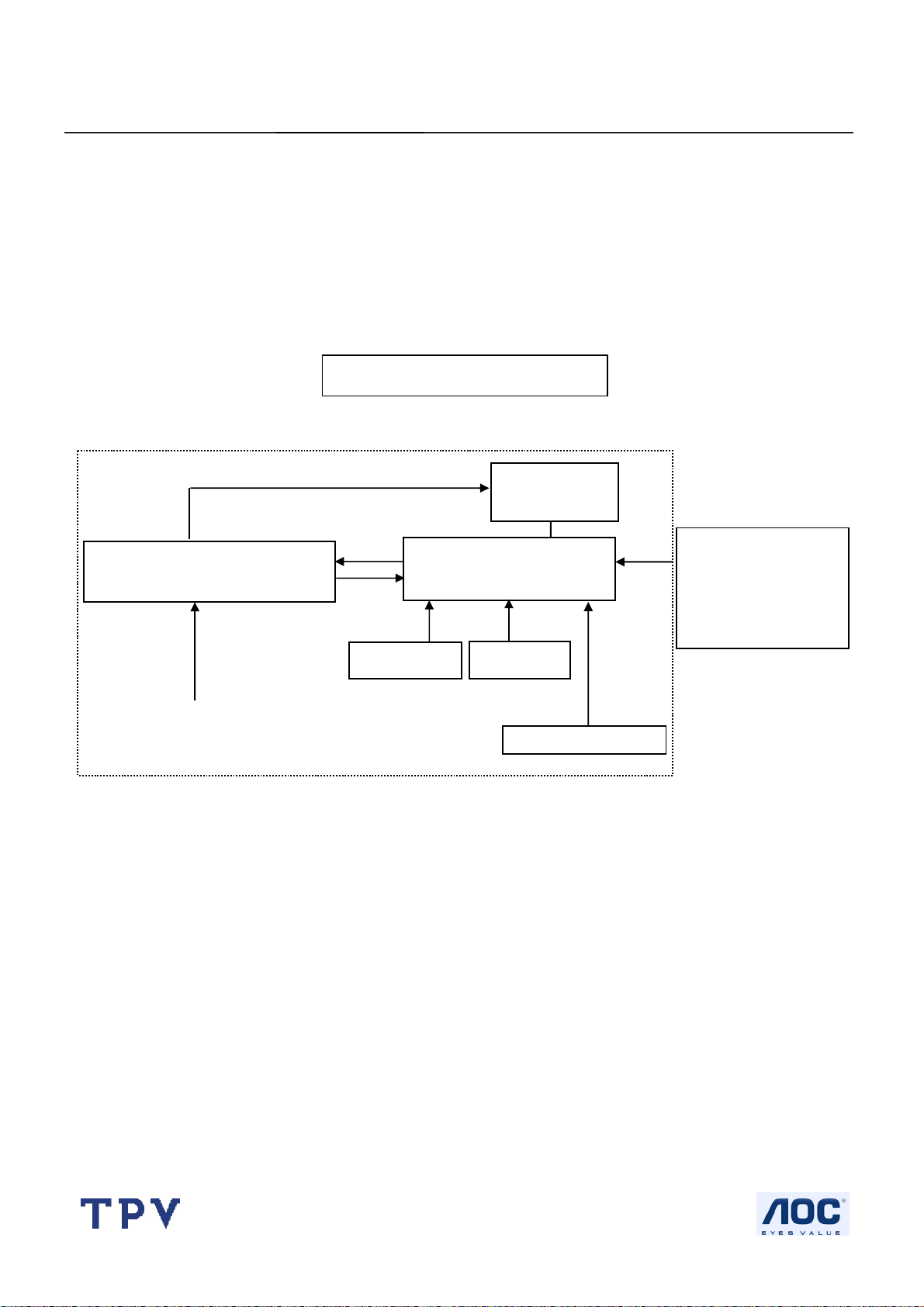
2. LCD Monitor Description
The LCD MONITOR will contain a main board, a power board, an audio board and a key board which house the flat
panel control logic, brightness control logic and DDC.
The power board will provide AC to DC Inverter voltage to drive the backlight of panel and the main board chips each
voltage.
Power board
(Include: adapter, inverter)
CCFL Drive.
Monitor Block Diagram
Flat Panel and
CCFL backlight
Main board
Audio board
Key board
RS232 Connector
For white balance
adjustment in factory
mode
Video signal, DDC
AC-IN
100V-240V
HOST Computer
http://www.wjel.net
5
Page 6
19" LCD Color Monitor I-INC AH191D
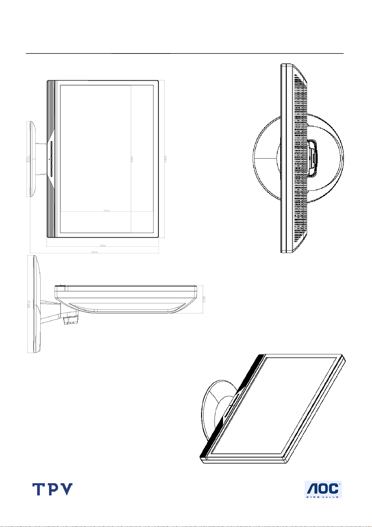
Dimensions
http://www.wjel.net
6
Page 7
19" LCD Color Monitor I-INC AH191D
3. Operating Instructions
3.1 General Instructions
Press the power button to turn the monitor on or off. The control buttons are located in the front of the monitor.
By changing these settings, the picture can be adjusted to your personal preferences.
The power cord should be connected.
-
Connect the video cable from the monitor to the video card.
-
Press the power button to turn on the monitor, the power indicator will light up.
-
3.2 Control Buttons
http://www.wjel.net
7
Page 8

19" LCD Color Monitor I-INC AH191D
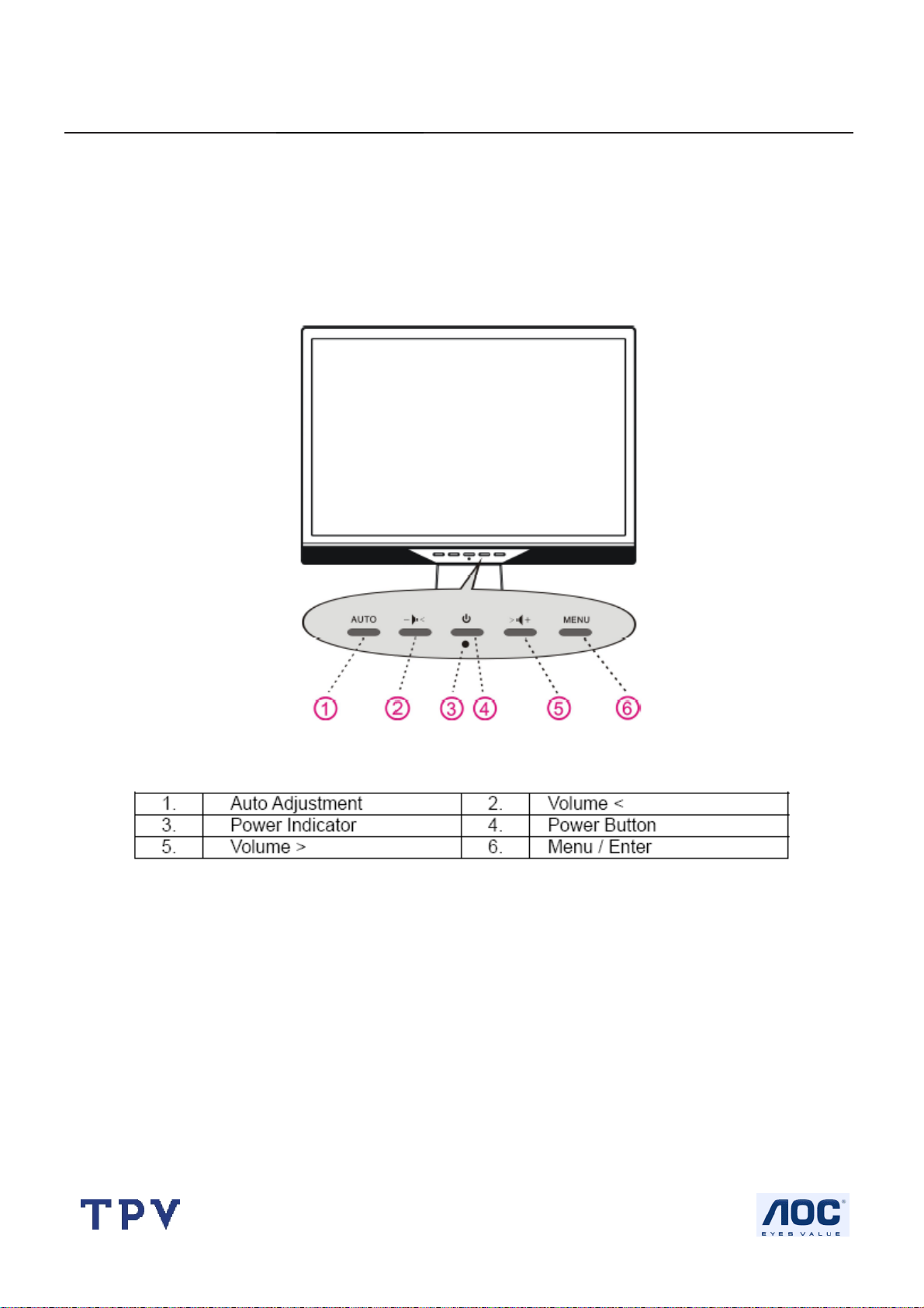
FRONT PANEL CONTROL
• Power Button:
Press this button to switch ON/OFF of monitor’s power.
• Power Indicator:
Green — Power On mode.
Orange — Off mode.
• MENU / ENTER:
1. Activate the OSD menu or adjust the function settings and confirmation or
2. Exit OSD menu when in volume OSD status.
• Volume < >:
1. Activates the volume control when the OSD is OFF.
2. Navigate through adjustment icons when OSD is ON or adjust a function when function is activated.
• Auto Adjust button:
When OSD menu is in off status, press this button to activate the Auto Adjustment function.
(The Auto Adjustment function is used to optimized the H-Position, V-Position, Clock and Focus.)
NOTES:
• Do not install the monitor in a location near heat sources such as radiators or air dusts, or in a place subject to direct
sunlight, or excessive dust or mechanical vibration or shock.
• Save the original shipping box and packing materials, as they will come in handy if you ever have to ship your monitor.
• For maximum protection, repackage your monitor as it was originally packed at the factory.
• To keep the monitor looking new, periodically clean it with a soft cloth. Stubborn stains may be removed with a cloth
lightly dampened with a mild detergent solution. Never use strong solvents such as thinner, benzene, or abrasive
cleaners, since these will damage the cabinet. As a safety precaution, always unplug the monitor before cleaning it.
http://www.wjel.net
8
Page 9
19" LCD Color Monitor I-INC AH191D
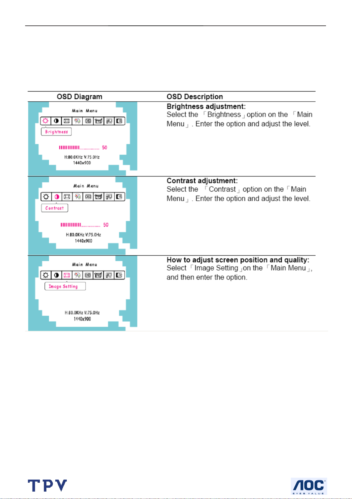
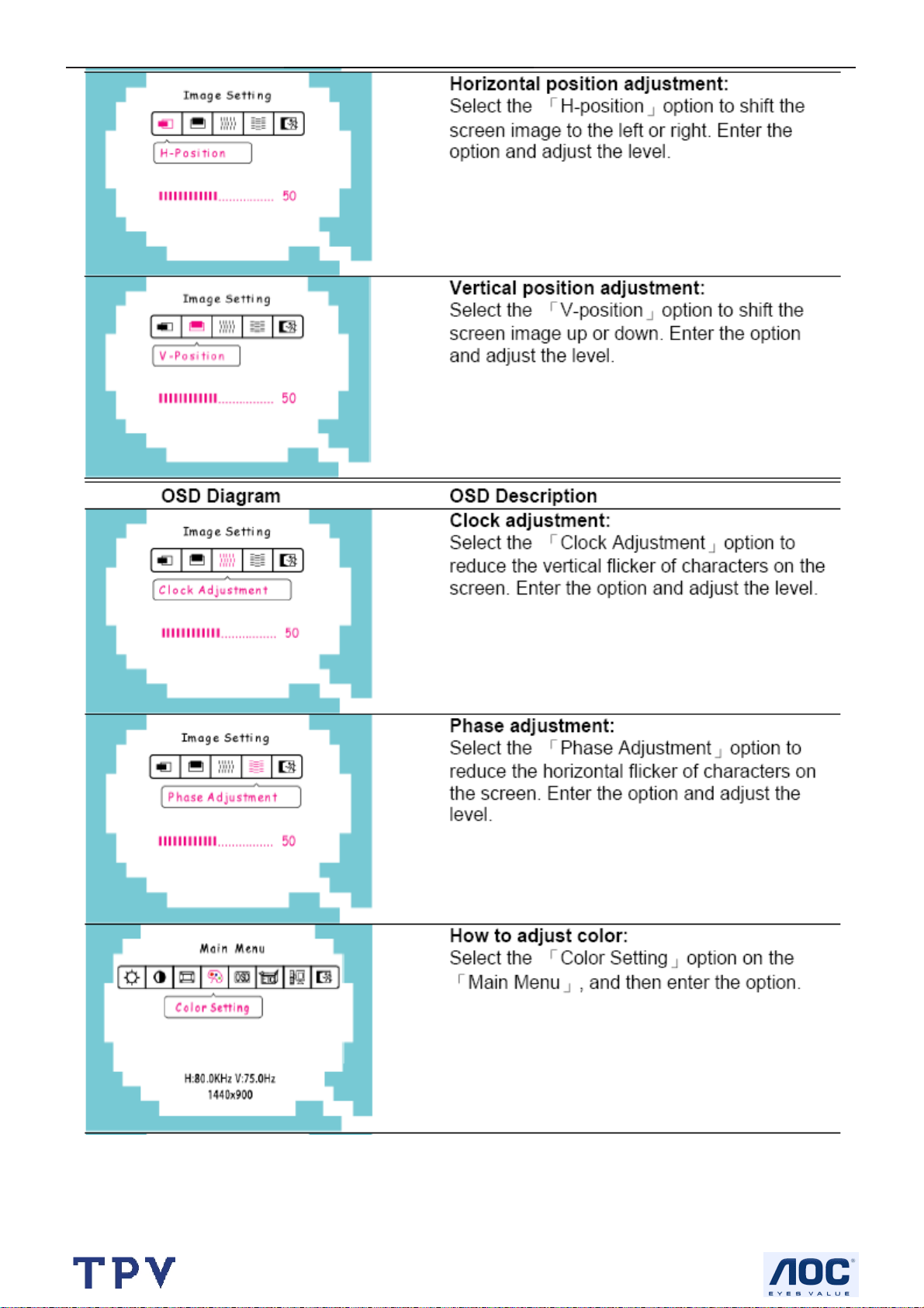
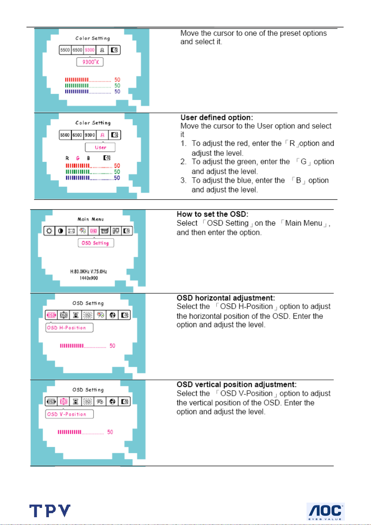
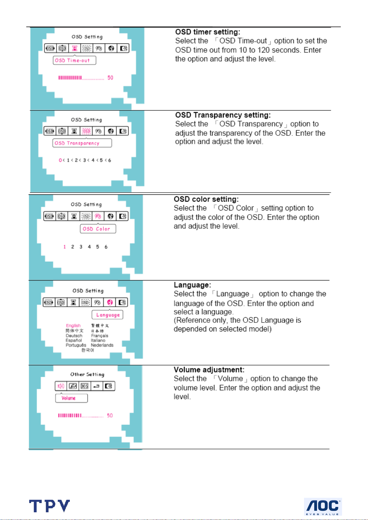
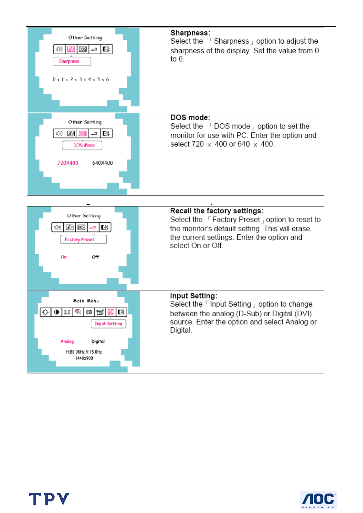
3.3 Adjusting the Picture
Adjustment steps:
1. Press the MENU-button to activate the OSD window.
2. Press < or > to select the desired function.
3. Press the MENU-button to select the function that you want to adjust.
4. Press < or > to change the settings of the current function.
5. To exit and save, select the exit function, or leave the monitor alone for 10 seconds. If you want to adjust any
other function, repeat steps 2-4.
http://www.wjel.net
9
Page 10
19" LCD Color Monitor I-INC AH191D
http://www.wjel.net
10
Page 11
19" LCD Color Monitor I-INC AH191D
http://www.wjel.net
11
Page 12
19" LCD Color Monitor I-INC AH191D
http://www.wjel.net
12
Page 13
19" LCD Color Monitor I-INC AH191D
http://www.wjel.net
13
Page 14
19" LCD Color Monitor I-INC AH191D
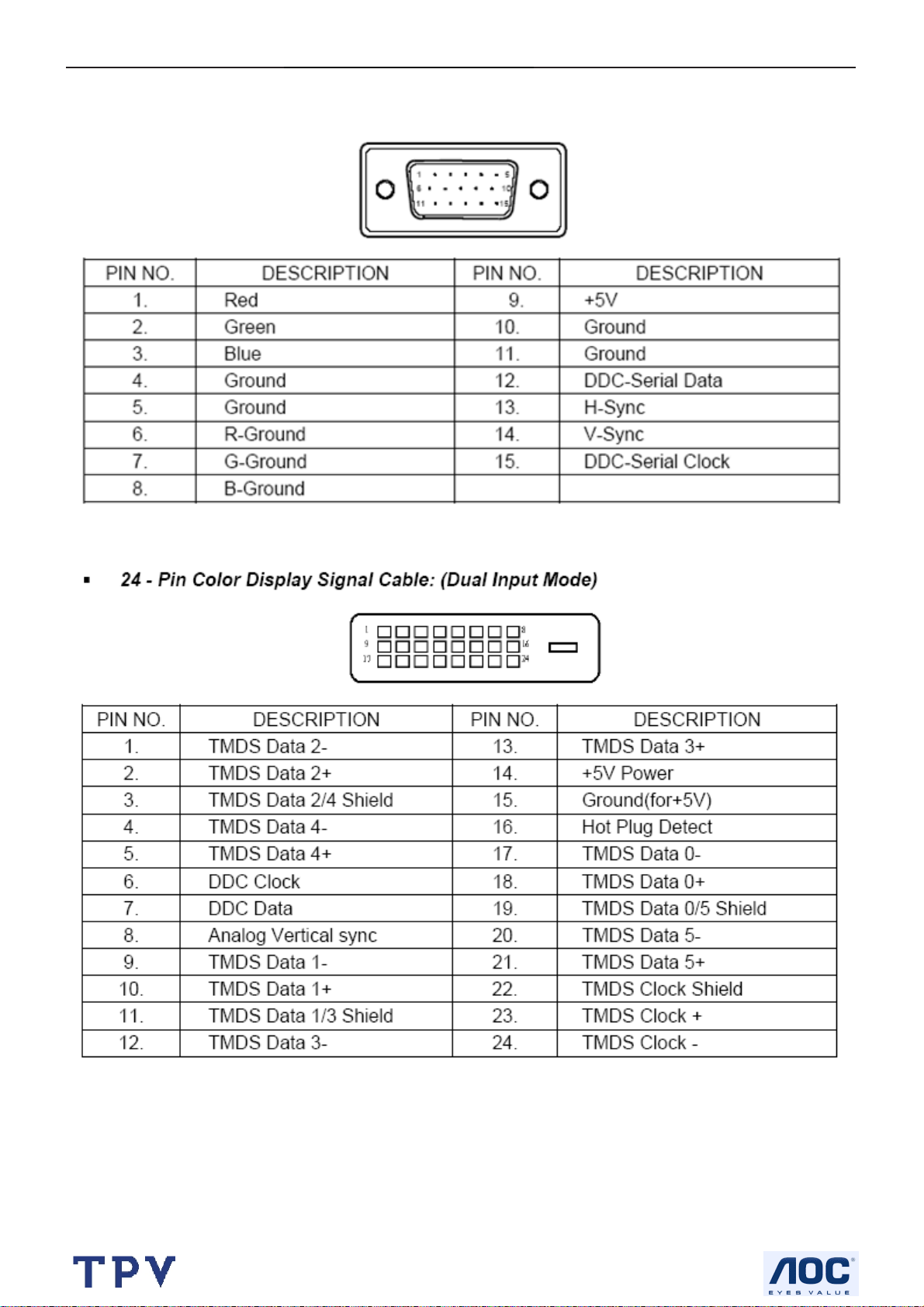
4. Input/Output Specification
4.1 Input Signal Connector
http://www.wjel.net
14
Page 15
19" LCD Color Monitor I-INC AH191D
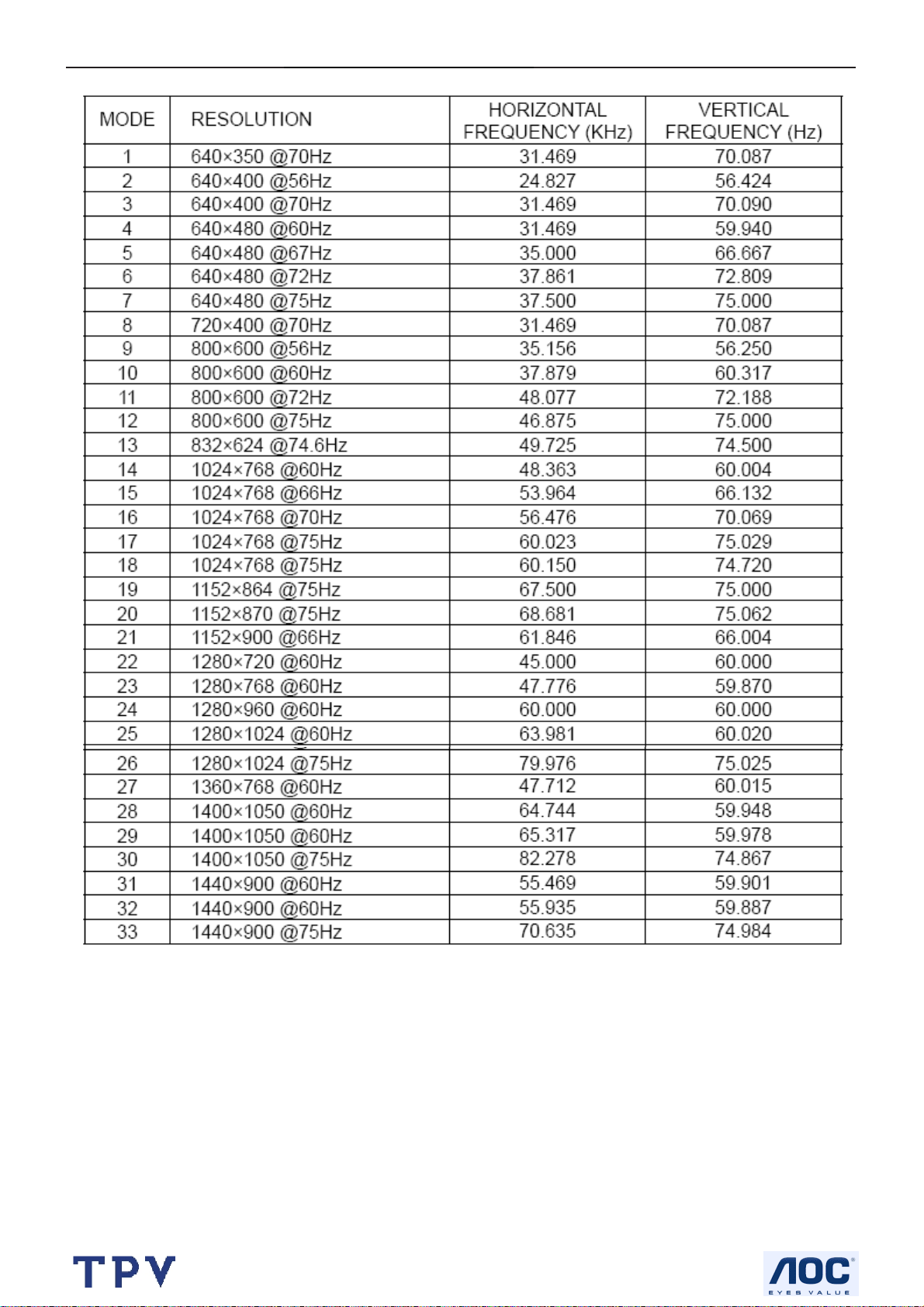
4.2 Factory Preset Display Modes
http://www.wjel.net
15
Page 16
19" LCD Color Monitor I-INC AH191D
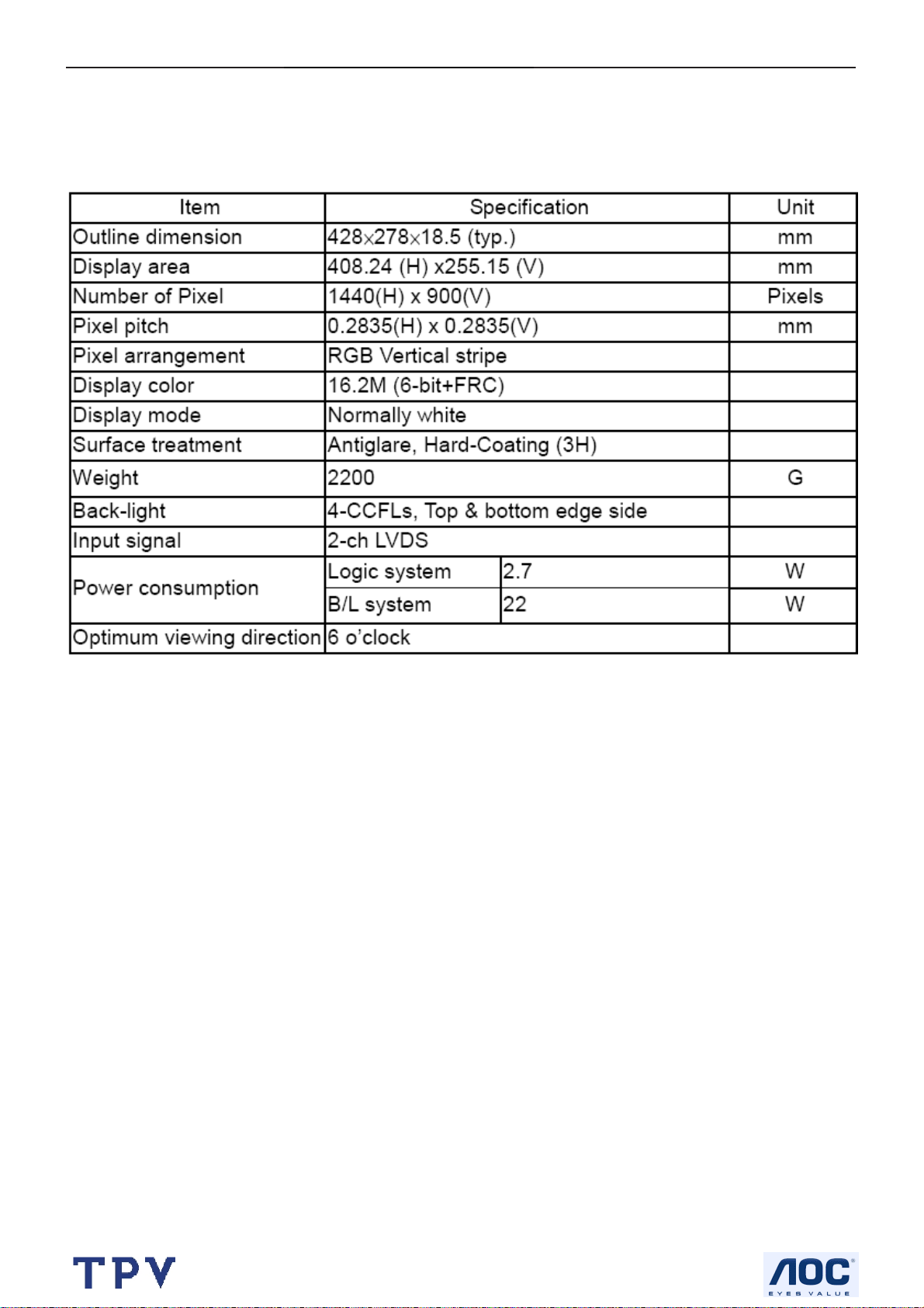
4.4 Panel Specification
HannStar Display model HSD190MGW1-A00 is a color active matrix thin film transistor (TFT) liquid crystal display
(LCD) that uses amorphous silicon TFT as a switching device. This model is composed of a TFT LCD panel, the
voltage reference, common voltage, DC-DC converter, column, and row driver circuit. This TFT LCD has a 19-inch
diagonally measured active display area with WXGA+ resolution (900 vertical by 1440 horizontal pixel array).
4.4.1 Display Characteristics
http://www.wjel.net
16
Page 17
19" LCD Color Monitor I-INC AH191D
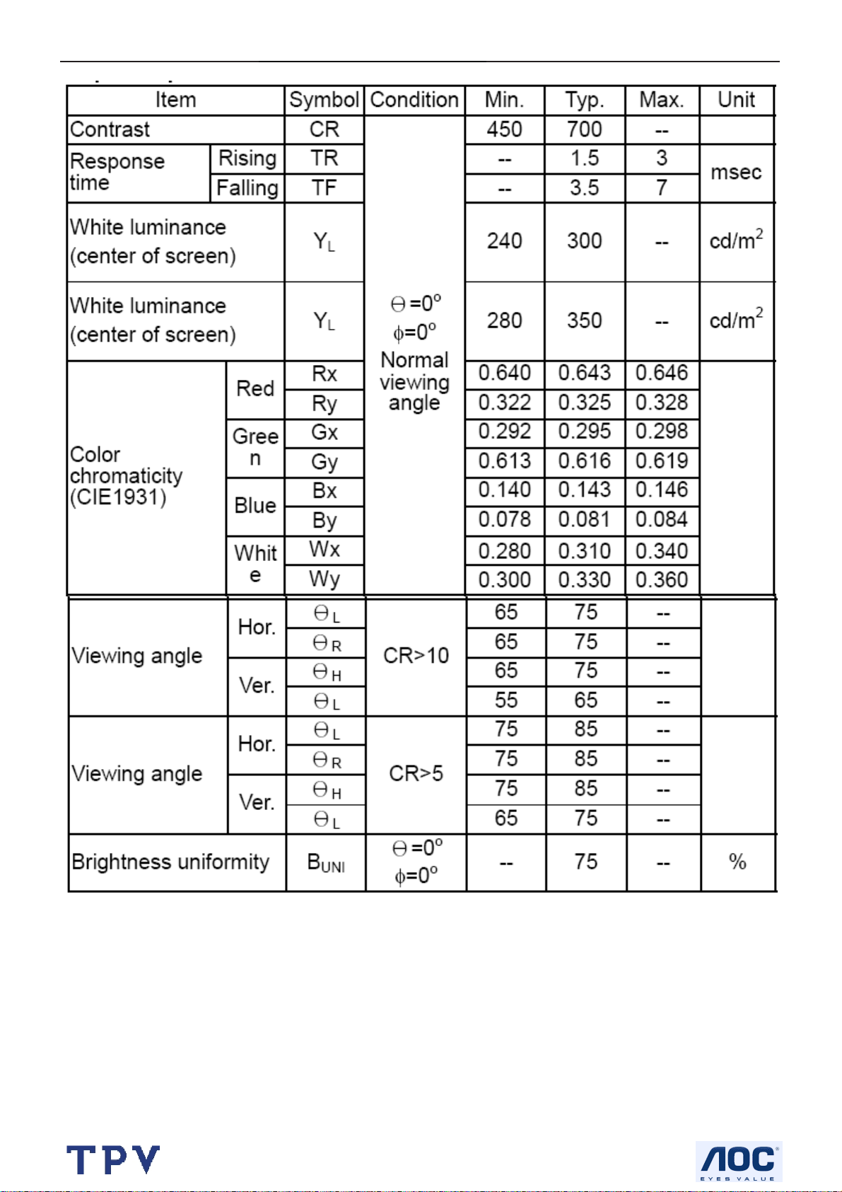
4.4.2 Optical Characteristics
http://www.wjel.net
17
Page 18
19" LCD Color Monitor I-INC AH191D
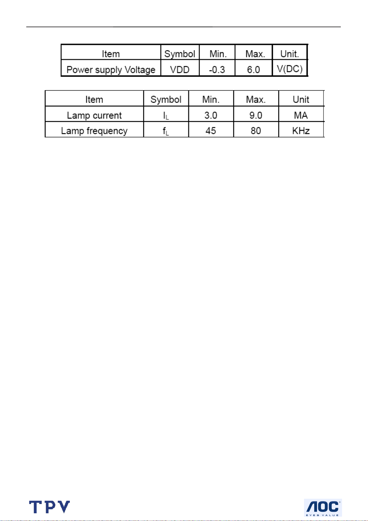
4.4.3 Parameter guide line for CCFL Inverter
TFT LCD Module:
Back Light Unit:
http://www.wjel.net
18
Page 19

19" LCD Color Monitor I-INC AH191D
5. Block Diagram
5.1 Software Flow Chat
1
2
N
4
5
Y
6
7
Y
N
N
3
9
10
Y
N
12
Y
http://www.wjel.net
14
18
N
19
N
11
13
15
17
N
Y
N
Y
16
Y
19
Page 20

19" LCD Color Monitor I-INC AH191D
1) MCU initialize.
2) Is the EPROM blank?
3) Program the EPROM by default values.
4) Get the PWM value of brightness from EPROM.
5) Is the power key pressed?
6) Clear all global flags.
7) Are the AUTO and SELECT keys pressed?
8) Enter factory mode.
9) Save the power key status into EPROM.
Turn on the LED and set it to green color.
Scalar initializes.
10) In standby mode?
11) Update the lifetime of back light.
12) Check the analog port, are there any signals coming?
13) Does the scalar send out an interrupt request?
14) Wake up the scalar.
15) Are there any signals coming from analog port?
16) Display "No connection Check Signal Cable" message. And go into standby mode after the message
disappear.
17) Program the scalar to be able to show the coming mode.
18) Process the OSD display.
19) Read the keyboard. Is the power key pressed?
http://www.wjel.net
20
Page 21

19" LCD Color Monitor I-INC AH191D
5.2 Electric Block Diagram
5.2.1 Main Board
Crystal (14.318MHz)
(X401)
EEPROM
M24C16
(U403)
Scalar TSUM56AK
(Include MCU, ADC, OSD)
(U401)
LCD interface
(CN101)
H sync
V sync
RGB
Digital
Video
Signal
D-Sub
Connector
(CN405)
DVI
Connector
(CN406)
EEPROM
M24C02
(U404)
EEPROM
M24C02
(U405)
http://www.wjel.net
21
Page 22

19" LCD Color Monitor I-INC AH191D
5.2.2 Inverter / Power Board
AC inlet Filter
Rectifier and
filter
Start circuit R904, R931, R938
Switching circuit
PWM control
IC&MOSFET
On/off control
Start circuit
PWM control IC
Transform
er
OVP/OCP circuit
Push-pull
circuit
Rectifier and
filter D908,
D909
To main board
Feedback
circuit IC902,
IC903
LC resonant
12V/5V
12V
Lamp
Dimming control
Feedback circuit
http://www.wjel.net
22
Page 23

19" LCD Color Monitor I-INC AH191D
6. Schematic
6.1 Main Board
TSUM16AWK SCHEMATIC
VCC3.3
XGA/SXGA
B3
+5V
+5V
RIN
GNDR
GIN
GNDG
SOG
BIN
GNDB
HSYNC
VSYN C
DDCA_SDA
DDCA_SCL
DET_VGA
DDC_WP
CLK+
CLK-
DDCD_SDA
DDCD_SCL
DET_DVI
R+
R-
G+
GB+
B-
B4
RIN
GNDR
GIN
GNDG
SOG
BIN
GNDB
HSYNC
VSYN C
DDCA_SDA
DDCA_SCL
DET_VGA
DDC_WP
R+
RG+
GB+
BCLK+
CLKDDCD_SDA
DDCD_SCL
DET_DVI
LVDS OUTPUT
VCC3. 3
VCC1.8
VCC1.8
Vcc3. 3
+5V
+12V
+5V
+12V
3.INP UT
B5
PA[0.. 7]
PA[8.. 13]
PA[14..19]
+12V
+3V3
VCC1.8
+5V
B2
+12V
+3V3
VCC1.8
+5V
VCC3.3
on_BACKLIGHT
on_Panel
on_PANEL_12V
VCTRL
Adj_BACKLIGHT
VLCD
VLCD_12V
VLCD VLCD_12V
http://www.wjel.net
on_BACKLIGHT
on_Panel
on_PANEL_12V
VCTRL
Adj_BACKLIGHT
4.SCALER
PB[0.. 5]
PB[6.. 11]
PB[12..23]
GPO[0.. 4]
ESP
OSP
2.POW ER
PA[0.. 7]
PA[8.. 13]
PA[14.. 19]
PB[0.. 5]
PB[6.. 11]
PB[12.. 23]
GPO[0.. 4]
PA[0.. 7]
PA[8.. 13]
PA[14.. 19]
PB[0.. 5]
PB[6.. 11]
PB[12.. 23]
GPO[0.. 4]
ESP
OSP
VLCD_12V
VLCD
VLCD
VLCD_12V
5.PANEL INTERFACE
Tit le
Size Document Number Rev
B
Date: Sheet
715G1558-C-BJ.DSN
TOP
15Friday , July 21, 2006
A
of
23
Page 24

19" LCD Color Monitor I-INC AH191D
+12V
U701
+5V
C701
NC
L701
+12V
4
1 2
120 OHM
C706
C707
+
0.1uF
+5V
+5V3,4
1 2
C709
0.1uF
adj_BACKLIGH T
100uF/25V
L702
120 OHM
NC/ LT1117-18
3 2
VI VO
GND
GND
GND
GND
C710
+
100uF/25V
R706
4
R707
4.7K 1/16W
SOT-223
4
VO
GND
1
BL_ADJ(DC)
R31
0V ~ 3.3V
4.7K
0V ~ 5V
4.7K
C32
R31
BL_ADJ
47
P W M
D C
N.C
4K7
1uF
CN701
1
3
5
7
9
11
CONN
+5V
NC
C51
1UF
1UF
2
4
6
8
10
12
R701
1K 1/16W
Q701
PMBS3904
BL_ON
BL_ADJ
GND
GND
R705
+
R32
0
X
4.7K 1/16W
C703
+3V3
+3V3
+
C704
NC
22uF/50V
C708
R33
X
4.7K
1uF
MMBT3904
1K 1/10W
R740
NC
+
Q4
X
R739
C723
22uF/50V
+5V
R708
10K 1/16W
C711
0.1uF
Q703
PMBS3904
D704(SSM12L) Vf=0.38V and If=1A.
So when system power on, the
system loading is about 400mA
(3.3V is about 200mA and 1.8V is
about 200mA), So D35 changed
from 1N4148(or BAT42) to
SSM12L(schottky diode).
P.S: The 1N4148 Vf=0.7V~1V can't meet
LDO spec. The BAT42, Vf is OK but the
If=200mA(forward current) can not
meet current spec.
R29
X
1K
H1
9
9
123
123
R710 NC
R712 4.7K 1/16W
H2
678
5
678
5
4
4
TP
+5V
9
9
123
123
R711
10K 1/ 16W
678
678
5
4
TP
on_BACKLIGH T 4
H3
5
4
678
5
9
678
9
5
4
4
123
TP
123
D702
SMAL140
R704
100 1/16W
del
+5V
+5V3,4
D704
SMAL140
C713
0.1uF
U702
3
1
AIC1084-33PM
Q702
PZT2907A
TO-263
VIN
VOUT
ADJ
del
D701
SMAL140
Recommond to used "Blue" parts circuit
for VCC1.8V if you want to suppoert DDC
function when system power off
2
R702
51 1/16W
C702
+
22uF/50V
R703
2K 1/16W
VCTRL 4
VCC3. 3
C712
+
100uF/25V
VCC1.8
VCC1. 8 4
VCC3.3 4
VCC3. 3
VCC3.3 4
C714
0.1uF
For LVDS PANEL
R733
NC
on_PANEL
4
R734
10K 1/16W
R735
4.7K 1/16W
C721
0.1uF
R716
NC
+3V3
+5V
Q708
PMBS3904
R717
10K 1/16W
R723 51K 1/16W
C715
0.022uF
Q706
PMBS3906
0.1uF
C727
C724
NC
1
VLCD_12V
32
Q705
NC
+
NC
C719
+5V
VLCD_12V 5
+12V
R730
NC
R728
NC
R731
NC
Tit le
Size Docum ent Number Rev
Custom
Date: Sheet
Power
715G1558-C-BJ.DSN
VLCD
Q704
AO3401L
+
C717
22uF/50V
VLCD 5
+5V
+3V3
R722
R721
NC
0 1/16W
R727
NC
on_PANEL_12V
For RSDS and Panel VCC=12V
+5V
+12V
R720
R736
NC
NC
R737 NC/ 4K7
C722
NC
4
PMBS3904
Q709
+5V
+12V
R719
R729
NC
NC
R724 51K
C716
NC
Q707
NC
http://www.wjel.net
24
35Friday , July 21, 2006
A
of
Page 25

19" LCD Color Monitor I-INC AH191D
CN406
RGB GND
HSYNC
VSYN C
SYNC GND
DDC SCL
DDC SDA
1/3shield
2/4shield
0/5shield
clk shield
DAT0+
DAT0-
DAT1+
DAT1-
DAT2+
DAT2-
DAT3+
DAT3-
DAT4+
DAT4-
DAT5+
DAT5-
JACK DVI
1716
11
12
13
14
15
HSI
VSI
D408
MLL5232B 5.6V
25
R
26
G
27
B
29
28
8
15
6
7
14
+5V
16
HPD
11
3
19
22
18
17
10
9
2
1
13
12
5
4
21
20
23
clk+
24
clk-
CN405
DB15
RED+
1
6
REDGREEN+
2
GREEN-
7
BLUE+
3
8
BLUE-
4
VGA5V
9
5
VGA_CON
10
MLL5232B 5.6V
SCL_DVI
SDA_DVI
DVI5V
HPD
DAT0+
DAT0DAT1+
DAT1DAT2+
DAT2-
DCLK+
DCLK-
R491
10K 1/ 16W
D406
FB409 430 OHM
D409
MLL5232B 5.6V
R472
NC
3
D417
BAV99
C447
1
2
0.1uF
2
3
D403
BAV99
C439 0.1uF
2
+5V
R471
10K 1/ 16W
R458 100 1/ 16W
D426
LL5232B 5.6V 5%
3
D418
BAV99
C448
1
0.1uF
PC5V
1
2
3
C440 0.1uF
2
3
D419
BAV99
C449
1
0.1uF
D404
BAV99
C441 0.1uF
1
2
R448
2.2K 1/16W
D414
LL5232B 5.6V 5%
3
D420
BAV99
C450
2
0.1uF
FB410 0 1/ 16W
FB411 0 1/ 16W
FB412 0 1/ 16W
R438
75 1/ 16W
3
D405
BAV99
ESD 5V
1
R446 1K 1/ 16W
C442
R449
22pF
2.2K 1/16W
DET_DVI 4
R455 100 1/ 16W
R456 100 1/ 16W
D415
LL5232B 5.6V 5%
3
3
D421
BAV99
http://www.wjel.net
C451
1
2
0.1uF
C452
2
1
0.1uF
D422
BAV99
ESD5V
1
R439
75 1/ 16W
R447 1K 1/ 16W
C443
22pF
D416
LL5232B 5.6V 5%
3
D423
BAV99
C453
1
2
0.1uF
R440
75 1/ 16W
D411
MLL5232B 5.6V
DVI5V
C445
0.1uF
R462 10 1/ 16W
R463 10 1/ 16W
R464 10 1/ 16W
R465 10 1/ 16W
R466 10 1/ 16W
R467 10 1/ 16W
R468 10 1/ 16W
R469 10 1/ 16W
3
D424
BAV99
C454
1
2
0.1uF
R434 56 1/ 16W
R435 56 1/ 16W
R436 56 1/ 16W
R437 470 1/ 16W
R441 100 1/ 16W
R442 100 1/ 16W
R443 100 1/ 16W
+5V
R444
10K 1/ 16W
D410
MLL5232B 5.6V
D412
MLL5232B 5.6V
R457
10K 1/ 16W
+5V 2,4
R445 100 1/ 16W
B+ 4
B- 4
G+ 4
G- 4
R+ 4
R- 4
CLK+ 4
CLK- 4
ESD 5V
C432 0.047uF
C433 0.047uF
C434 0.047uF
C435 0.047uF
C436 0.047uF
C437 0.047uF
C438 0.047uF
SCL_VGA
SDA_VGA
+5V
R470
D425
1 2
DDCA_SDA4
DDCA_SCL4
DDCD_SDA4
DDCD_SCL4
10K 1/10W
RLZ36B
RIN 4
GIN 4
BIN 4
SOG 4
GNDR 4
GNDG 4
GNDB 4
DET_VGA 4
HSYNC 4
VSYN C 4
R450
10K 1/ 16W
R453 100 1/ 16W
R454 100 1/ 16W
R459
10K 1/ 16W
+5V
PC5V
1
2
D407
BAV70
R451
10K 1/ 16W
R460
10K 1/ 16W
3
R452
10K
+5V
R461
10K
Tit le
Size Docum ent Num ber Rev
B
Date: Sheet
U404
8
7
6
DVI5V
1
2
3
R473
NC
VCC
WP
SCL
M24C02
D413
BAV70
U405
8
7
6
M24C02
VCC
WP
SCL
A0
A1
A2
GNDSDA
A0
A1
A2
GNDSDA
C444
1
0.22uF
2
3
45
DDC_WP 4
C446
1
0.22uF
2
3
45
DDC_WP 4
Input
715G1558-C-BJ.DSN
45Friday , July 21, 2006
of
A
25
Page 26

19" LCD Color Monitor I-INC AH191D
VCC3.3
R403 390 1%
C401
2
SDO
1
CE#
6
SCK
R492
20
R493
20
R415
59
58
56
55
57
54
53
63
64
65
66
39
40
42
43
45
46
48
49
36
37
51
62
0.1uF
61
70
71
72
73
19
32
33
102
104
R416
10K 1/16W
+5V
R430
1K 1/16W
Q404
PMBS3904
DDCA_SDA3
DDCA_SCL3
+5V
+
C418
10uF/50V
R404
10K 1/16W NC
+5V
Reset
Circuit
C417
0.22uF
10K 1/16W
U406
R489
10K 1/16W
VCC3.3
R486
NC
R487
10K 1/16W
23
RSTVCC
GND
ASM810MEURF-T
1
R490
GNDR3
GNDG3
GNDB3
HSYNC3
VSYNC3
DDCD_SDA3
DDCD_SCL3
AVDD
U402
8
VDD
7
HOLD#
3
WP#
4 5
VSS SD I
WP
C421 22pF
X401
14.318MHz
C423 22pF
VCC3.3
R407 NC
R410 NC
RIN3
GIN3
SOG3
BIN3
R+3
R-3
G+3
G-3
B+3
B-3
CLK+3
CLK-3
SST25VF010-20-4C-SAE
10K 1/16W
R431 NC
R433 4.7K 1/16W
VDVI
VMPLL
44
50
AVDD_DVI
AVDD_DVI
RIN0P
RIN0M
GIN0P
GIN0M
SOGIN0
BIN0P
BIN0M
HSYNC0
VSYNC0
DDCA_SDA
DDCA_SCL
R+
RG+
GB+
BCK+
CKDDCD_SDA
DDCD_SCL
REXT
REFP
REFM
SDO
CSZ
SCK
SDI
RST
XIN
XOU T
MODE [0]
MODE [1]
R432 10K 1/16W
VPLL
AVDD
52344
60
BYPASS
AVDD_PLL
AVDD_ADC
AVDD_MPLL
RSDS/LVDS/TTL
GND
GND
GND
GND
41
47
3896116
13
C431
1uF/25V
VDDP
67
14
95
103
VDDP
VDDP
VDDP
VDDP
GND
GND
OUT-L+
OUT-L-Volume
VDDC
12
68
97
115
117
VDDP
VDDC
VDDC
VDDC
VDDC
NC/LVACKP/NC
NC/LVACKM/NC
RA1P/LVA2P/RA2
RA1N/ LVA2M/RA3
RA2P/LVA1P/RA4
RA2N/ LVA1M/RA5
RA3P/LVA0P/RA6
RA3N/ LVA0M/RA7
GA3P/LVA3P/GA6
GA3N/LV A3M/GA7
RB1P/NC/RB2
RB1N/NC/RB3
RB2P/NC/RB4
RB2N/NC/RB5
RB3P/NC/RB6
RB3N/NC/RB7
GB1P/NC/GB2
GB1N/NC/ GB3
GB2P/NC/GB4
GB2N/NC/ GB5
GB3P/NC/GB6
GB3N/NC/ GB7
CLKAP/LVB3P/ LHSYN C
CLKAN/LVB3M/LVSYNC
CLKBP/LVBC KP/LCK_ODD
CLKBN/L VBCKM/LDE
NC/LVB2 P/NC
NC/LVB2M/NC
BB1P/LVB1P/BB2
BB1N/LVB1M/BB3
BB2P/LVB0P/BB4
BB2N/LVB0M/BB5
BB3P/NC/BB6
BB3N/NC/BB7
GPIO_P22
GPIO_P23
GPIO_P03
GPIO_P16/PWM2
GPIO_P15/PWM0
PWM2/GPIO_P24
GPIO_P27/PWM1
GPIO_P12
PWM1/GPIO_P25
GPIO_P00/SAR1
GPIO_P01/SAR2
GPIO_P02/SAR3
GPIO_P06
GPIO_P07
PWM0/GPIO_P26
GPIO_P13
GPIO_P14
GPIO_P10/I2C_MCL
GPIO_P11/I2C_MDA
FB407
600 OHM
FB408
600 OHM
CN404
1
3
5
7
9
11
13
CONN
VDDC
FB401
VCC1.8
VCC1.82
11
VCTRL
107
PA0
108
PA1
109
PA2
110
PA3
PA4
111
PA5
112
PA6
113
PA7
114
PA8
98
NC
99
PA9
NC
100
PA10
NC
PA11
101
NC
105
PA12
106
PA13
89
PA14
NC
PA15
90
NC
PA16
91
NC
92
PA17
NC
PA18
93
NC
94
PA19
NC
9
PB0
10
PB1
15
PB2
PB3
16
17
PB4
PB5
18
2
PB6
3
PB7
5
PB8
PB9
6
7
PB10
8
PB11
118
PB12
PB13
119
120
PB14
121
PB15
122
PB16
PB17
123
124
PB18
PB19
125
PB20
126
127
PB21
128
PB22
PB23
1
80
ESP
NC
OSP
81
NC
88
GPO0
NC
GPO1
87
NC
86
GPO2
NC
85
GPO3
NC
84
GPO4
NC
83
NC
82
NC
75
74
26
35
69
R488 100R 1/10W
78
79
20
21
22
RSTN
R418 100 1/16W
23
R420 100 1/16W
24
R411 100 1/16W
25
27
R422 4.7K 1/16W
R423 4.7K 1/16W
28
29
30
31
VCC3.3
77
76
R424
10K 1/16W
+12V
+12V 2
+5V
+5V 2,3
R484
10K 1/16W
2
4
6
http://www.wjel.net
8
10
12
OUT-R+
OUT-R-
14
R425
10K 1/16W
R428 100 1/16W
R429 100 1/16W
+5V
R485
10K 1/16W
AUDIO_STBY
AUDIO_MUTE
VCTRL 2
P[0..7]
PA[8..13]
PA[14..19]
PB[0..5]
PB[6..11]
PB[12..23]
GPO[0..4]
WP
KEY1
KEY2
POWER
Volume
AUDIO_MUTE
AUDIO_STBY
R426
10K 1/16W
R427 100 1/16W
Option
PA[0..7] 5
PA[8..13] 5
PA[14..19] 5
PB[0..5] 5
PB[6..11] 5
PB[12..23] 5
ESP 5
OSP 5
GPO[0..4] 5
R405
22K 1/16W
10K 1/16W
on_PANEL_12V 2
DET_DVI 3
DET_VGA 3
on_PANEL 2
on_BACKLIGHT 2
adj_BACKLI GHT 2
U403
8
VCC
7
WP
6
SCL
AT24C16N-10SC-2.7
KEY_B
LED_G
KEY_AUTO
KEY_RI GHT
POWER
OUT-L+
OUT-L-
VCC3.32
DDC_WP 3
Q402
PMBS3904
C422
0.1uF
R406
C425
0.22uF
1
A0
2
A1
3
A2
45
GNDSDA
CN403
1
3
5
7
9
11
13
15
CONN
VCC3.3
R481
R482
NC
NC
Q405
NC
KEY_A
2
LED_A
4
6
KEY_MENU
KEY_LEFT
8
10
12
KEY_C
OUT-R+
14
16
OUT-R-
R483
NC
KEY2
KEY1
LED_G
LED_A
POWER
C426
KEY A
C616
NC
C429
C427
C428
0.1uF
0.1uF
0.1uF
0.1uF
+5V
R412
10K 1/16W
R417 20K 1/16W
C424 0.1uF
3.9K 1/16W
C430
D401
0.1uF
RLZ36B
1 2
VCC3.3
VCC3.32
VCC3.32
+5V 2,3
10K 1/16W
600 OHM
600 OHM
R474
22uF/50V
FB403
R413
VCC3.3
D402
1 2
C403
RLZ36B
+
C404
0.1uF
C408
22uF/50V
VCC3.3
VCC3.3
+5V
R475
3.9K 1/16W
C405
0.1uF
VDDP
+
FB404
600 OHM
FB406
600 OHM
R414
240 1/16W
Q401
PMBS3906
R421 0 1/16W
C406
0.1uF
C409
C411
C410
0.1uF
0.1uF
0.1uF
VDVI
C415
C414
0.1uF
0.1uF
VMPLL
C419
C420
0.1uF
0.1uF
10K 1/16W
LED_G
R476 1K 1/16W
R477 1K 1/16W
Title
Size Document Number Rev
C
Date: Sheet
VCC3.32
C412
0.1uF
R408
C413
0.1uF
VCC3.32
R478 1K 1/16W
R479 1K 1/16W
VCC3.3
+5V
R409
75 1/16W
Q403
PMBS3906
R480 1.5K 1/16W
Scaler
715G1558-C-BJ.DSN
FB402
600 OHM
VCC3.3
R419 0 1/16W
AVDD
FB405
600 OHM
LED_A
KEY_AUTO
KEY_RI GHT
KEY_MENU
KEY_LEFT
C407
0.1uF
VPLL
C416
0.1uF
KEY_A
KEY_B
KEY_C
A
25Friday, July 21, 2006
of
26
Page 27

19" LCD Color Monitor I-INC AH191D
VLCD
R89
PB[0. .5]
PB0
RB1P
RB1N
PB1
RB2P
PB2
PB3
RB2N
PB4
RB3P
PB5
RB3N
PB[6.. 11]
PB6
GB1P
GB1N
PB7
PB8
GB2P
PB9
GB2N
PB10
GB3P
GB3N
PB11
PB[12.. 23]
CLKBP
PB14
CLKBN
PB15
PB18
BB1P
BB1N
PB19
BB2P
PB20
PB21
BB2N
BB3P
PB22
PB23
BB3N
R101 NC/0
OSP
ESP
R102 NC/0
C106
NC
R91
Table 1
X
X
X
V
V
V
Table 1
AU 17
QDI 17
CPT 17
INNOLUX 15
HannStar 15
CPT 15
LG 15
Innolux 17"
R90
3.3V
3.3V
3.3V
3.3V
NC
0R
0R
0R
0R
NC
C107
NC
R103 NC
R104 NC
R105 NC
R106 NC
R107 NC
R108 NC
R109 NC
R92
NC
12V
0R
NC
NC
NC
NC
RA3N
RA3P
RA2N
RA2P
RA1N
RA1P
GA3N
GA3P
GA2N
GA2P
GA1N
GA1P
CLKAN
CLKAP
BA3N
BA3P
BA2P
BA1N
BA1P
GPOO1
GPOO0
GPOO3
GPOO2
GPOO4
R93
3.3V
3.3V
3.3V
3.3V
FB0N
FB0P
FB1N
FB1P
FB2N
FB2P
FG0N
FG0P
FG1N
FG1P
FG2N
FG2P
FCLKN
FCLKP
FR0N
FR0P
FR1N
FR1P
FR2N
FR2P
STH
LP
POL
STV2
CLKV
STV1
OE
R94
5V
0R
NC
0R
0R
0R
3.3V
0R
R95
5V
0R
NC
NC
NC
NC
0R
CN102
1
2
3
4
5
6
7
8
9
10
11
12
13
14
15
16
17
18
19
20
21
22
23
24
25
26
27
28
29
30
31
32
33
34
35
36
37
38
39
40
41
42
43
44
45
46
47
48
49
50
IL-FHR -B50S-HF (JAE)
R97
R96
5V
NC
0R
12V
0R
NC
NC
NC
12V
0R
NC
NC
NC
3.3V
0R
NC
CN103
RXO0RXO1RXO2RXOCRXO3RXE0RXE1RXE2RXECRXE3-
R738
VLCD
1
2
3
4
5
6
7
8
9
10
11
12
13
14
15
16
17
18
19
20
21
22
23
24
25
26
27
28
29
30
IL-FH R-B30S-HF (JAE)
CN101
2
1
4
3
6
5
8
7
10
9
CONN
L703
BEAD 120OHM
1 2
R741
150R 1/4W
12
14
16
18
20
22
24
26
28
30
VLCD 2
C726
0.1uF/ 16V
11
13
15
17
19
21
23
25
27
29
RXO0+
RXO1+
RXO2+
RXOC+
RXO3+
RXE0+
RXE1+
RXE2+
RXEC+
RXE3+
LVB0P
LVB1P
LVB2P
LVBCKP
LVB3P
LVA0P
LVA1P
LVA2P
LVACKP
LVA3PC101
RB3N
B0N
B0P
RB3P
B1N
RB2N
B1P
RB2P
RB1N
B2N
B2P
RB1P
BG0N
GB3N
GB3P
BG0P
BG1N
GB2N
GB2P
BG1P
GB1N
BG2N
BG2P
GB1P
BCLKN
CLKBN
BCLKP
CLKBP
BR0N
BB3N
BR0P
BB3P
BB2N
BR1NBA2N
BB2N
BR1P
BB2P
BR2N
BB1N
BR2P
BB1P
LVB0M
LVB1M
LVB2MGPOO3
LVBCKM
LVB3M
LVA0M
LVA1M
LVA2M
LVACKM
LVA3M
NC
12V
0R
NC
NC
NC
NC
C725
22uF/50V
+
150R 1/4W
CN8
PB[0..5]4
PB[6.. 11]4
PB[12.. 23]4
OSP4
ESP4
VLCD2
VLCD_12V
VLCD_12V2
R88
RP1
CN9
X
X
X
V
V
V
X
V
PA[0..7]
PA0
LVACKP
PA1
LVACKM
PA2
LVA2P
PA3
LVA2M
PA4
LVA1P
PA5
LVA1M
PA6
LVA0P
PA7
LVA0M
PA12
LVA3P
LVA3M
PA13
PB[12.. 23]
PB12
LVB3P
PB13
LVB3M
PB14
LVBCKP
PB15
LVBCKM
LVB2P
PB16
PB17
LVB2M
LVB1P
PB18
LVB1M
PB19
LVB0P
PB20
PB21
LVB0M
C104
NC
LVDS Panel
RSDS Panel
C105
NC
GPOO0
GPOO1
GPOO2
GPOO4
CN7
X
V
8
7
6
C103
C102
NC
NC
NC
PA2
PA3
PA4
PA5
PA6
PA7
PA8
PA9
PA10
PA11
PA12
PA13
PA14
PA15
PA16
PA17
PA18
PA19
PB12
PB13
GPO0
GPO1
GPO2
GPO3
GPO4
PA[0. .7]4
RA1P
RA1N
RA2P
RA2N
RA3P
RA3N
GA1P
GA1N
GA2P
GA2N
GA3P
GA3N
PB[12..23]4
BA1P
BA1N
BA2P
BA2N
BA3P
BA3N
CLKAP
CLKAN
RP101 NC
1
2
3
4 5
R110 NC
PA[0..7]4
PA[8..13]4
PA[14.. 19]4
GPO[0.. 4]4
PA[0..7]
PA[8..13]
GPO[0.. 4]
Tit le
http://www.wjel.net
Size Document Number Rev
B
Date: Sheet
PANEL INTERFACE
715G1558-C-BJ.DSN
55Friday , July 21, 2006
27
of
A
Page 28

19" LCD Color Monitor I-INC AH191D
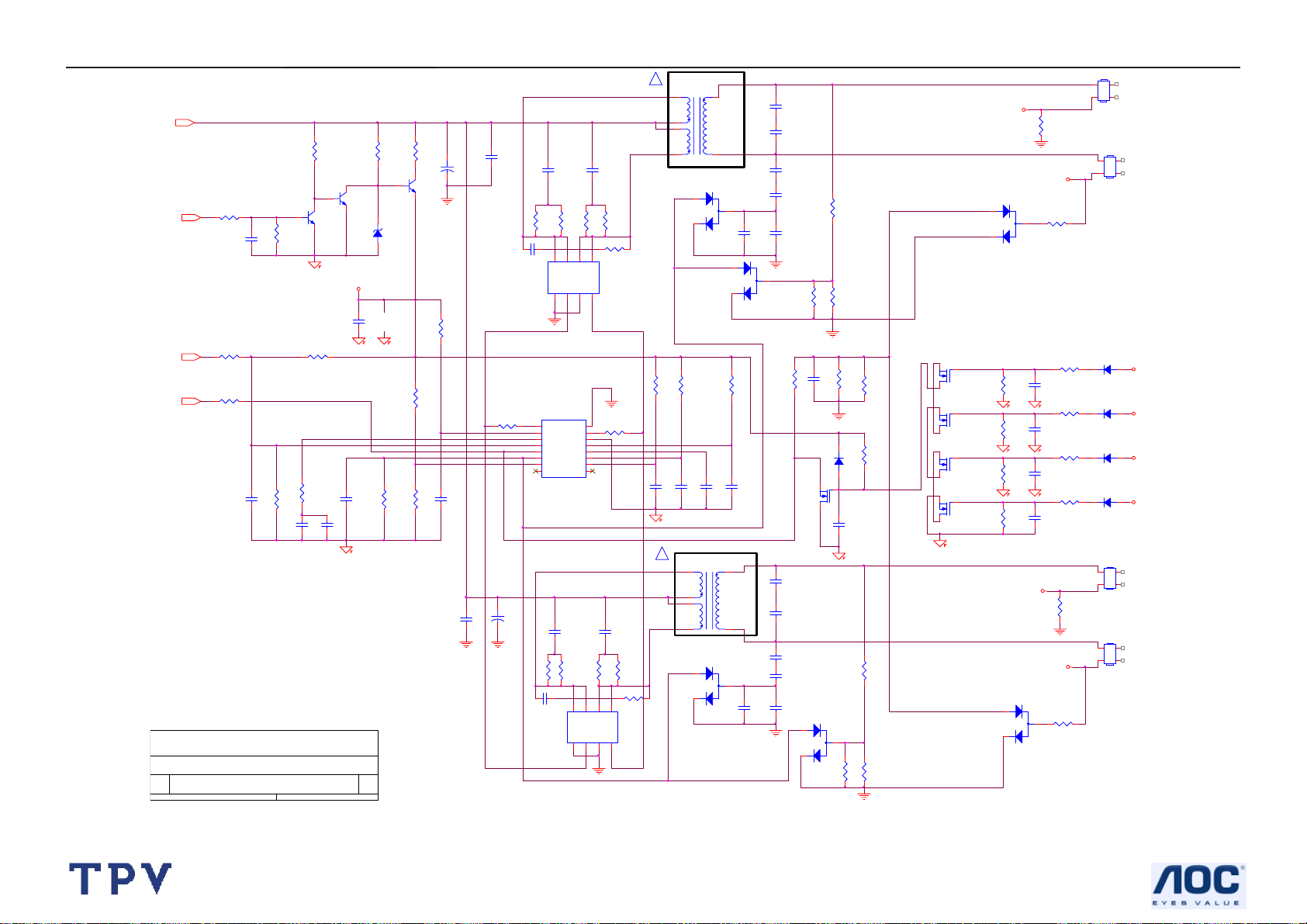
6.2 Power Board
D908
SP20150
2
D909
SP20100
2
C932
0.0015uF/2KV
C933
0.0015uF/2KV
R920
1K 0805
C918
0.1uF
R921
1K 0805
R934
47 1206
R935
47 1206
C934
JUMP
C936
470uF/25V
C935
470uF/25V
R937
100 1206
R936
100 1206
R916
100 1206
Over voltage protection
ZD901
RLZ13B
1 2
R926
2K 0805
C931
1000PF/5 00V
+
+
1 2
+
ZD902
RLZ5.6B
+
C912
470uF/25V
C904
470uF/25V
R927
10KΩ 1/4W
3.6K 0805 1%
C919
0.1uF
R922
1K 0805
L903
3.5UH
+
C937
470UF/25V
L904
3.5UH
R925
R923
33K 0805 1%
R924
2.4K 0805 1%
AOC (Top Victory) Electronics Co., Ltd.
Titl e
1.POWER OUTPUT 12V & 5 V
Size Document Number Rev
G1899-1-HP-X-1-060720
Date: Sheet
Friday , July 21, 2006
+
C911
470UF/25V
1 2
PTZ9.1B
ZD903
ON/OFF
C916
0.1uF
F903
FUSE
F902
FUSE
DIM
12
11
10
9
8
7
6
5
4
3
2
1
C917
0.1uF
11
+12V
+5V
CN902
of
ON/OFF
DIM
NC
GND
GND
GND
GND
GND
+5V
+5V
+12V
+12V
1
1
-+
2
3
2
3
L902
1
4
VAR901
NC
2
3
L901
2.0MH
1
4
C903
0.47uF/ 275V
R902
R901
680KΩ 1/4W
680KΩ 1/4W
3
CN901
SOCKET
BD901
4A 800V
4
73L 174-65-LS
R903
680KΩ 1/4W
NR901
NTCR
12
C905
100uF/4 50V
C901
1000PF/2 50V
C902
1000PF/2 50V
12
t
F901
FUSE
!
+
1 2
Over voltage protection
ZD906
R941
NC
NC
C913
NC
C908
0.1uF
IC901
LD7575
R913
100K 0805
8
LD7575
7
N.C
RT1CS
R906
6
4
2
1
IC902
T901
C900
0.0022UF
!
47 1206
R919
470Ω 1/4W
12
IC903
KIA431A-AT/P
3
1
95
10
7
3
8
11
12
1
43
R931
100KΩ 1/4W
R904
100KΩ 1/4W
R938
100KΩ 1/4W
6
HV
OUT
GND
COMP
4
2
ZD907
NC
R939
NC
NC
IC904
R905
100K 2W
C930
0.0015uF /2KV
D903
0Ω 1/4W
C907
+
R910
22Ω 1/4W
RLZ18B
TO PI N3
D904
ZD904
C909
220pF
NC
1N4148W
1 2
R911
1KΩ 1/4W
C910
470pF/50V
ZD905
NC
1 2
TO PI N3
VCC
5
3
1 2
R912
12
10K 0805
D901
FR107
Q903
STP10NK70ZFP
R914
0.47 2W
D902
R909
5.1Ω 1/4W
FR103
C906
+
22UF/50V
FB901
BEAD
Over current protection
80GL17T 37 L GP
http://www.wjel.net
28
Page 29
19" LCD Color Monitor I-INC AH191D
PT801
!
80GL19T 8 DN GP
5
+12V
R804
R802
300KΩ 1/8W
10K 0805
ON/OFF
R803
10K 0805
C801
R806
10K 0805
0.1uF
R808
200K 0805
DIM
PID
R801
NC
C803
0.01uF
R811
47K 0805
C804
1uF/25V
10K 0805
Q801
PMBS3904
C840
1uF/25V
R809
180KΩ 1/8W
R812
C814
0.22uF/25V
Q802
PMBS3904
VCC
AOC (Top Victory) Electronics Co., Ltd.
Titl e
HP W19 series 17" 19'' 4 LAMPS INVERTER
Size Document Number Rev
G1899-1-HP-X-1-060720
Tuesday, February 27, 2007
Date: Sheet
11
of
C805
1000pF
7
3
4
R805
470Ω 1/4W
+
C811
Q803
470UF/25V
PMBS3904
ZD801
RLZ5.6B
1 2
R807
22Ω 1/4W
R810
1MΩ 1/8W
R813
1MΩ 1/8W
R814
750KΩ 1/8W
C829
0.1uF
C806
1uF/25V
http://www.wjel.net
1
C828
0.1uF
5.1Ω 1/4W
R842
+
C815
470UF/25V
?
Q806
AM9945
R828
IC801
1
DRV1
2
VDDA
3
TIMER
4
DIM
5
ISEN
6
VSEN
7
OVPT
NC18NC2
OZ9938
R863
?
AM9945
332/1206
C822
30 1206
30 1206
8
S1N1G1N2S2N3G2N
PGND
DRV2
GNDA
SSTCMP
C813
R818
30 1206
30 1206
Q805
R861
30 1206
D2N5D2N6D1N7D1N
4
16
15
14
13
CT
12
11
LCT
10
ENA
9
332/1206
8
S1N1G1N2S2N3G2N
R829
332/1206
C823
5.1Ω 1/4W
R837
R819
30 1206
D2N5D2N6D1N7D1N
4
R862
30 1206
?
332/1206
C812
1 8
D801
1
3
2
BAV99
1
D806
2
BAV99
R816
1MΩ 1/8W
R815
100K 1/ 8W
C807
C808
0.01uF
0.0068uF
!
5
3
4
1 8
R864
30 1206
?
C809
0.047uF
PT802
80GL19T 8 DN GP
D803
1
2
BAV99
R817
33KΩ 1/8W
7
3
C820
470pF/50V
C810
560PF/50V
C831
470pF/50V
3
82KΩ 1/8W
R825
51KΩ 1/8W
C816
22pF/3KV
C841
22pF/3KV
C825
5pF/3KV
C824
5pF/3KV
C818
0.0033uF/16V
R823
Q804
RK7002
C834
22pF/3KV
C837
22pF/3KV
C826
5pF/3KV
C835
5pF/3KV
C827
0.0033uF/16V
1
2
82KΩ 1/8W
C819
0.047uF
D809
1N4148W
D805
R830
R822
6.2MΩ 1/2W
R827
7.5K /0805
R826
430 0805 1%
open lamp protection
C844
0.1uF
BAV99
3
R841
430 0805 1%
R860
1MΩ 1/8W
R832
6.2MΩ 1/2W
R831
7.5K 0805
Q807
RK7002
1MΩ 1/8W
Q808
RK7002
1MΩ 1/8W
Q809
RK7002
1MΩ 1/8W
Q810
RK7002
1MΩ 1/8W
D802
R846
R847
R848
R849
OPT1
R836
1K 1/ 10W
OPT2
1
2
BAV99
R858
3
750Ω 1/8W
C838
0.1uF
C839
0.1uF
C842
0.1uF
C843
0.1uF
OPT3
OPT4
D804
1
BAV99
R824
3
2
750Ω 1/8W
R853
R852
R850
R851
1K 0805
R843
CONN
4.7KΩ 1/8W
4.7KΩ 1/8W
4.7KΩ 1/8W
4.7KΩ 1/4W
CN801
CONN
CONN
CONN
1342
CN802
D810
1N4148W
D811
1N4148W
D812
1N4148W
D813
1N4148W
CN803
CN804
1342
OPT1
OPT2
OPT3
OPT4
1342
1342
29
Page 30

19" LCD Color Monitor I-INC AH191D
6.3 Key Board
ESD by jc chen
2006/5/11
GND wire
SW001
KEY SEL
CN002
EAR PHONEJACK
SW002
KEY LEFT
1
5
4
3
2
7
8
GND
POWER KEY
BZX79-B5V6
SW003
R101 75
R102 75
ZD102
1 2
GND
SW004
KEY RIGHT
1 2
GND
SPKR_R+
SPKR_L+
ZD101
BZX79-B5V6
SW005
GREEN
KEY MANU
1
2
GND
1
2
GND
ESD by jc chen
2006/5/11
KEY_SEL
KEY_LEFT
POWER_ KEY
KEY RIGHT
KEY_MANU
LED_ORANGE
1
3
DP101
ORANGE
LED
2
CN003
SPK-R
CN004
SPK-L
ESD by jc chen
2006/5/11
GND wire
LED_ORANGE
KEY_SEL
KEY_RIGHT
POWER_ KEY
GND
SPKR_L+
11
1
3
5
7
9
CN001
CONN
2
4
6
8
10
12
LED_GRN
KEY_MANU
KEY_LEFT
GNDLED_GRN
SPKR_R+
GND
GND
AOC (Top Victory) Electronics Co., Ltd.
Title
http://www.wjel.net
Size Document Number Rev
A
Date: Sheet
715G2127-1
11Tuesday, June 13, 2006
of
c
30
Page 31

19" LCD Color Monitor I-INC AH191D
6.4 Audio Board
OUT_L
MUTE
15
16
VS
VS
OUTR
VAROUT_R
VAROUT_L
GND
GND
GND
13
181920
+12V
OUTL
SVR
GND
+
C201
470uF/16V
U201
E-TDA7496L
17
14
10
7
5
C208
470uF/16V
+
C202
470uF/16V
+
R202
200K
GND
C205
470uF/16V
R207
1K
C203
0.1uF
+
470uF/16V
R208
1K
OUT_R
+
C207
CN204
1
2
3
CONN
CN201
AUDIO INPUT JACK
1
5
4
3
2
GND
GND
ZD201
BZX79-B5V6
12V
CN202
14
12
GND
C210
+
1uF/50V
10
8
6
4
2
CONN
STANDBY
C213
0.1uF
VOLUME
R201
R203 18K
ZD202
BZX79-B5V6
1 2
1 2
18K
C211
100pF
R210
20K
R211
20K
R212
220K
C212
100pF
C214
NC
+12V
C209
+
1uF/50V
C204
0.47uF/100V
C206
0.47uF/100V
4
9
6
11
12
13
11
9
7
5
3
1
INL
INR
VOLUME
STBY
MUTE
123
8
GND
NC
GND
GND
GND
GND
GND
http://www.wjel.net
GND
Title
Size Document Number Rev
Date: Sheet
GND
<Doc> 1A
GND
715G2128-1
11Tuesday, June 13, 2006
of
31
Page 32

19" LCD Color Monitor I-INC AH191D
7. PCB Layout
7.1 Main Board
http://www.wjel.net
32
Page 33

19" LCD Color Monitor I-INC AH191D
http://www.wjel.net
33
Page 34

19" LCD Color Monitor I-INC AH191D
7.2 Power Board
http://www.wjel.net
34
Page 35

19" LCD Color Monitor I-INC AH191D
http://www.wjel.net
35
Page 36

19" LCD Color Monitor I-INC AH191D
7.3 Key Board
7.4 Audio Board
http://www.wjel.net
36
Page 37

19" LCD Color Monitor I-INC AH191D
8. Maintainability
8.1 Equipments and Tools Requirement
1. Voltmeter.
2. Oscilloscope.
3. Pattern Generator.
4. DDC Tool with an IBM Compatible Computer.
5. Alignment Tool.
6. LCD Color Analyzer.
7. Service Manual.
8. User Manual.
http://www.wjel.net
37
Page 38

19" LCD Color Monitor I-INC AH191D
8.2 Trouble Shooting
8.2.1 Main Board
No Power
Press power key and look
if the picture is normal
Please reinsert and make sure
the AC of 100-240 is normal
Measure U702 Vout=3.3V
Q702 Vc=1.8V
X401 oscillate waveforms
are normal
No power
NG
OK
OK
OK
Replace U401
NG
NG
NG
Reinsert or check the
Adapter/Inverter
section
Check CN701 or replace
U702, Q702
Replace X401
NG
Replace U401
http://www.wjel.net
38
Page 39

19" LCD Color Monitor I-INC AH191D
No Picture (LED orange)
Measure U702 Vout=3.3V
Q702 Vc=1.8V
No picture
The button if under
control
OK
OK
X401 oscillate
waveform is normal
OK
Check HS/VS from
CN405 is normal
OK
Replace U401
NG
NG
NG
X401 oscillate
waveform is normal
OK
Check reset circuit of
U401 is normal
Replace U401
NG
Replace U702, Q702
Replace X401
Check Correspondent
component
OK
NG
Replace X401
NG
Check Correspondent
component
http://www.wjel.net
39
Page 40

19" LCD Color Monitor I-INC AH191D
White Screen
Replace CN101 or
re-solder
Measure C725 (+) =5V
Check CN101 connector or
solder normal?
White screen
OK
NG
OK
NG
Checks Q704, Q706,
Q708 are broken
NG
OK
Check X401
OK
Replace U401
Replace Q704,
Q706, Q708
NG
Replace X401
Replace PANEL
http://www.wjel.net
40
Page 41

19" LCD Color Monitor I-INC AH191D
8.2.2 Power Board
1. No Power
Check to CN902 Pin1, 2 =12V and Pin3, 4 = 5 V
No power
OK
NG
Check Interface board
Check AC line volt 120V or 220V
OK
NG
Change F901, Check BD901, Q903, IC901
Check the voltage of C905 (+)
OK
NG
Check bridge retified circuit
Check start voltage for the Pin6 of IC901
OK
NG
Change IC901
Check the auxiliary voltage is smaller than 20V
NG
OK
http://www.wjel.net
Check D908, D909, ZD903…
Check IC902,IC903
Check Q903…OLP circuit
41
Page 42

19" LCD Color Monitor I-INC AH191D
2. W/LED No Backlight
Check C811 (+) =12V
OK
NG
Check adapter circuit
Check ON/OFF signal
OK NG
Check Interface board
Check IC801 PIN2=5V
Check the Pin1, Pin15 of IC801 have square wave
NGOK
Check Q801,Q802,Q803
OK
NG
Check IC801
Check Q805,Q806 have the output of
square wave at short time.
OK
Check the resonant wave of Pin7 & Pin8 for PT801/PT802
OK
Check the output of PT801/PT802
NG
NG
Check Q805,Q806,PT801,PT802
Check C816, C841 or C834, C837
http://www.wjel.net
Change PT801 or PT802
Check connecter & lamp
42
Page 43

19" LCD Color Monitor I-INC AH191D
8.2.3 Key Board
OSD is unstable or not working
Is Keypad board connecting normally?
OK
Is Button Switch normally?
OK
Is Keypad board normally?
OK
Check main board
NG
Connect Keypad Board
NG
Replace Button Switch
NG
Replace Keypad Board
http://www.wjel.net
43
Page 44

19" LCD Color Monitor I-INC AH191D
9. White- Balance, Luminance Adjustment
Approximately 30 minutes should be allowed for warm up before proceeding White-Balance adjustment.
1. How to do the Chroma-7120 MEM. Channel setting
A. Reference to chroma 7120 user guide
B. Use “SC” key and “NEXT” key to modify x,y,Y value and use “ID” key to modify the
TEXT description Following is the procedure to do white-balance adjust
2. Setting the color temp. you want
A. MEM.CHANNEL 3 (9300 color):
9300 color temp. parameter is x = 283 ±28, y = 297 ±28,Y=220cd/㎡
B. MEM.CHANNEL 4 (6500 color):
6500 color temp. parameter is x = 313±28, y = 329 ±28, Y=220cd/㎡
C. MEM.CHANNEL 9 (5500 color):
5500 color temp. parameter is x = 333±28, y = 348 ±28, Y=220cd/㎡
3. Enter into factory mode of AH191D
Turn on the power, press simultaneously the MENU and AUTO buttons, then the factory OSD will be at the left top of
the panel.
4. Bias adjustment:
Set the Contrast
5. Gain adjustment:
Move cursor to “-F-” and press MENU key
A. Adjust 9300 color-temperature
1. Switch the Chroma-7120 to RGB-Mode (with press “MODE” button)
2. Switch the MEM. Channel to Channel 3 (with up or down arrow on chroma 7120)
3. The LCD-indicator on chroma 7120 will show x = 283 ±28, y = 297 ±28, Y=220cd/㎡
4. Adjust the RED of color 1 on factory window until chroma 7120 indicator reached the value R=100
5. Adjust the GREEN of color 1 on factory window until chroma 7120 indicator reached the value G=100
6. Adjust the BLUE of color 1 on factory window until chroma 7120 indicator reached the value B=100
7. Repeat above procedure (item 4,5,6) until chroma 7120 RGB value meet the tolerance =100±2
B. Adjust 6500 color-temperature
1. Switch the chroma-7120 to RGB-Mode (with press “MODE” button)
2. Switch the MEM.channel to Channel 4(with up or down arrow on chroma 7120)
3. The LCD-indicator on chroma 7120 will show x = 313 ±28, y = 329 ±28, Y=220cd/㎡
4. Adjust the RED of color 2 on factory window until chroma 7120 indicator reached the value R=100
5. Adjust the GREEN of color 2 on factory window until chroma 7120 indicator reachedthe value G=100
6. Adjust the BLUE of color 2 on factory window until chroma 7120 indicator reached the value B=100
7. Repeat above procedure (item 4,5,6) until chroma 7120 RGB value meet the tolerance =100±2
C. Adjust 5500 color-temperature
1. Switch the chroma-7120 to RGB-Mode (with press “MODE” button)
2. Switch the MEM.channel to Channel 9 (with up or down arrow on chroma 7120)
3. The LCD-indicator on chroma 7120 will show x = 333±28, y = 348 ±28, Y=220cd/㎡
4. Adjust the RED of color 3 on factory window until chroma 7120 indicator reached the value R=100
5. Adjust the GREEN of color 3 on factory window until chroma 7120 indicator reachedthe value G=100
6. Adjust the BLUE of color 3 on factory window until chroma 7120 indicator reached the value B=100
7. Repeat above procedure (item 4,5,6) until chroma 7120 RGB value meet the tolerance =100±2
D. Turn the Power-button off to quit from factory mode.
to 50; Adjust the Brightness to 80.
http://www.wjel.net
44
Page 45

19" LCD Color Monitor I-INC AH191D
10. Monitor Exploded View
http://www.wjel.net
45
Page 46

19" LCD Color Monitor I-INC AH191D
11. BOM List
T96HM6DTWEHZAE
Location Part No. Description
78G 322E02 L SPEAKER
78G 322E02 R SPEAKER
Q1G1030 10128 CR3 SCREW
AUPC6QA5P AUDIO BOARD
CBPC6HM6HCQP CONVERSION BOARD FOR 19
KEPC6QA6P KEY BOARD
PWPC942HT1P POWER BOARD
52G 1186 SMALL TAPE
52G 1207 A TAPE
52G6020 17 PROTECT FILM
89G 173 56 4B AUDIO CABLE
89G 715HAA D2 SIGNAL CABLE
89G1745CAA 9 SIGNAL CABLE
89G420A18N IS POWER CORD
95G8014 16E05 WIRE HARNESS
95G8018 3515 LVDS CABLE
M1G 340 8225 CR3 SCREW 4*8mm
M1G1140 6128 CR3 SCREW
M1G1730 6128 CR3 SCREW M3x6
M1G1730 6128 CR3 SCREW M3x6
M1G1730 6128 CR3 SCREW M3x6
M1G3030 5225 CR3 SCREW
Q1G 330 8120 SCREW 3X8mm
Q1G 330 8120 SCREW 3X8mm
Q1G 330 12 47 CR3 SCREW
705GH9K0F34003 ASS'Y
750GLH90GW111N PANEL LCD 19"MG1 A00
A15G0032 H7 MAIN FRAME
A33G0030 ZT 1L 32 CABLE COVER
A34G0051 ZT 1B REAR COVER
H26G 800850 1A BARCODE
H40G 19N850 2A ID LABEL
H41G7800850 3A QSG FOR AH191
H41G7800850 8B RECYCLE INFORMATION
H44G9030850 1B CARTON
H45G 87 1 4H EPE COVER
H45G 87 4 H PE BAG FOR BASE/MANUAL
H45G 87 4 H PE BAG FOR BASE/MANUAL
H52G 1175 4 MIDDLE TAPE FOR CARTON
H52G 1175 5 BIG TAPE FOR CARTON
H70G1600850 1B CD MANUAL
Q40G 58170931A HI-POT PASS LABEL
Q40G0002850 2A EPA LABEL
Q44G9030 1 EPS
http://www.wjel.net
46
Page 47

19" LCD Color Monitor I-INC AH191D
Q44G9030 2 EPS
Q45G 88606 14 PE BAG
Q52G6025 13 40 MYLAR
AIAUPC6QA5P AUDIO BOARD FOR AI
CN202 33G802414C H 2*7PIN DUAL ROW RIGHT A
U201 56G 616 31 IC TDA7496T 1.2W*2 DIP-
C201 67G215D4713KV LOW ESR EC 470UF 16V
C202 67G215D4713KV LOW ESR EC 470UF 16V
C207 67G215D4713KV LOW ESR EC 470UF 16V
C205 67G215Y4713RV 470UF +-20% 16V
C208 67G215Y4713RV 470UF +-20% 16V
CN201 88G 30210K E PHONE JACK
715G2128 1 AUDIO BOARD PCB
J201 95G 90 23 TINCOATEDCOPPER
R207 61G 60210252T CFR 1K OHM+-5% 1/6W
R208 61G 60210252T CFR 1K OHM+-5% 1/6W
R201 61G 60218352T 18KOHM 5% 1/6
R203 61G 60218352T 18KOHM 5% 1/6
R210 61G 60220352T CFR 20K OHM+-5% 1/6W
R211 61G 60220352T CFR 20K OHM+-5% 1/6W
R202 61G 60220452T 200KOHM 5% 1/6W
R212 61G 60222452T 220KOHM 5% 1/6W
C211 65G 444101 5T 100 PF 10% 50V Y5P
C212 65G 444101 5T 100 PF 10% 50V Y5P
C203 65G 450104 7T 0.1UF +80-20% 50V Y5V
C213 65G 450104 7T 0.1UF +80-20% 50V Y5V
C204 67G 70478 9T 0.47UF +-20% 100V
C206 67G 70478 9T 0.47UF +-20% 100V
C209 67G 309109 7T 1.0UF +-20% 50V
C210 67G 309109 7T 1.0UF +-20% 50V
SMTC6HM6HCQP MAIN BOARD
CN404 33G801714H H WAFER OR PLUG
CN701 33G8027 12 WAFER 2*6P 2.0MM R/A
CN403 33G8027 16 WAFER 16PIN 2.0mm DIP
CN101 33G8027 30 H WAFER 30P 2.0MM RIGHT A
40G 457624 1B CPU LABEL
40G 45762412B CBPC LABEL
44G3231508512 GASKET
C418 67G215V100 7N KY50VB10-M-CC3 5*11.5MM
C717 67G215V100 7N KY50VB10-M-CC3 5*11.5MM
C710 67G215V101 4N KY25VB100M-CC3(6.3*11)
C712 67G215V101 4N KY25VB100M-CC3(6.3*11)
C707 67G215V470 4R LOW E.S.R 47UF +/-20% 2
C403 67G215Y2207NV KY50VB22M-CC3 5*11
C408 67G215Y2207NV KY50VB22M-CC3 5*11
C702 67G215Y2207NV KY50VB22M-CC3 5*11
C723 67G215Y2207NV KY50VB22M-CC3 5*11
C725 67G215Y2207NV KY50VB22M-CC3 5*11
http://www.wjel.net
47
Page 48

19" LCD Color Monitor I-INC AH191D
CN405 88G 35315F HJ SOC SUBD H 15P F
CN406 88G 35424F HL DVI 24PIN FEMALE
U401 90G6250 1 GP HEAT SINK
X401 93G 22 53 14.31818MHZ HC-49US
U401 56G 562129 IC TSUM56AK-LF-1 PQFP-1
U702 56G 563 7 AIC1084-33PM
U404 56G1133 34 M24C02-WMN6TP
U405 56G1133 34 M24C02-WMN6TP
U403 56G1133 56 M24C16-WMN6TP
U402 56G1133 59 SST25VF010-20-4C-SAE S0
Q402 57G 417 4 PMBS3904/PHILIPS-SMT(04
Q404 57G 417 4 PMBS3904/PHILIPS-SMT(04
Q701 57G 417 4 PMBS3904/PHILIPS-SMT(04
Q703 57G 417 4 PMBS3904/PHILIPS-SMT(04
Q401 57G 417 6 PMBS3906/PHILIPS-SMT(06
Q403 57G 417 6 PMBS3906/PHILIPS-SMT(06
Q706 57G 417 6 PMBS3906/PHILIPS-SMT(06
Q702 57G 417 17 T PZT2907A
Q704 57G 763 1 AO3401L SOT23 BY AOS(A1
FB410 61L0603000 RST SM 0603 JUMP MAX 0R
FB411 61L0603000 RST SM 0603 JUMP MAX 0R
FB412 61L0603000 RST SM 0603 JUMP MAX 0R
R419 61L0603000 RST SM 0603 JUMP MAX 0R
R421 61L0603000 RST SM 0603 JUMP MAX 0R
R721 61L0603000 RST SM 0603 JUMP MAX 0R
R462 61L0603100 RST CHIP 10OHM +-5% 1/1
R463 61L0603100 RST CHIP 10OHM +-5% 1/1
R464 61L0603100 RST CHIP 10OHM +-5% 1/1
R465 61L0603100 RST CHIP 10OHM +-5% 1/1
R466 61L0603100 RST CHIP 10OHM +-5% 1/1
R467 61L0603100 RST CHIP 10OHM +-5% 1/1
R468 61L0603100 RST CHIP 10OHM +-5% 1/1
R469 61L0603100 RST CHIP 10OHM +-5% 1/1
R492 61L0603100 RST CHIP 10OHM +-5% 1/1
R493 61L0603100 RST CHIP 10OHM +-5% 1/1
R478 61L0603100 1F CHIP 1KOHM 1/16W 1%
R479 61L0603100 1F CHIP 1KOHM 1/16W 1%
R411 61L0603101 RST SM 0603 RC0603 100R
R418 61L0603101 RST SM 0603 RC0603 100R
R420 61L0603101 RST SM 0603 RC0603 100R
R427 61L0603101 RST SM 0603 RC0603 100R
R428 61L0603101 RST SM 0603 RC0603 100R
R429 61L0603101 RST SM 0603 RC0603 100R
R441 61L0603101 RST SM 0603 RC0603 100R
R442 61L0603101 RST SM 0603 RC0603 100R
R443 61L0603101 RST SM 0603 RC0603 100R
R445 61L0603101 RST SM 0603 RC0603 100R
R453 61L0603101 RST SM 0603 RC0603 100R
http://www.wjel.net
48
Page 49

19" LCD Color Monitor I-INC AH191D
R454 61L0603101 RST SM 0603 RC0603 100R
R455 61L0603101 RST SM 0603 RC0603 100R
R456 61L0603101 RST SM 0603 RC0603 100R
R458 61L0603101 RST SM 0603 RC0603 100R
R488 61L0603101 RST SM 0603 RC0603 100R
R704 61L0603101 RST SM 0603 RC0603 100R
R430 61L0603102 RST SM 0603 RC0603 1K P
R446 61L0603102 RST SM 0603 RC0603 1K P
R447 61L0603102 RST SM 0603 RC0603 1K P
R476 61L0603102 RST SM 0603 RC0603 1K P
R477 61L0603102 RST SM 0603 RC0603 1K P
R701 61L0603102 RST SM 0603 RC0603 1K P
R739 61L0603102 RST SM 0603 RC0603 1K P
R404 61L0603103 CHIPR 10K OHM +-5% 1/16
R406 61L0603103 CHIPR 10K OHM +-5% 1/16
R408 61L0603103 CHIPR 10K OHM +-5% 1/16
R412 61L0603103 CHIPR 10K OHM +-5% 1/16
R413 61L0603103 CHIPR 10K OHM +-5% 1/16
R415 61L0603103 CHIPR 10K OHM +-5% 1/16
R416 61L0603103 CHIPR 10K OHM +-5% 1/16
R424 61L0603103 CHIPR 10K OHM +-5% 1/16
R425 61L0603103 CHIPR 10K OHM +-5% 1/16
R426 61L0603103 CHIPR 10K OHM +-5% 1/16
R432 61L0603103 CHIPR 10K OHM +-5% 1/16
R444 61L0603103 CHIPR 10K OHM +-5% 1/16
R450 61L0603103 CHIPR 10K OHM +-5% 1/16
R451 61L0603103 CHIPR 10K OHM +-5% 1/16
R452 61L0603103 CHIPR 10K OHM +-5% 1/16
R457 61L0603103 CHIPR 10K OHM +-5% 1/16
R459 61L0603103 CHIPR 10K OHM +-5% 1/16
R460 61L0603103 CHIPR 10K OHM +-5% 1/16
R461 61L0603103 CHIPR 10K OHM +-5% 1/16
R470 61L0603103 CHIPR 10K OHM +-5% 1/16
R471 61L0603103 CHIPR 10K OHM +-5% 1/16
R484 61L0603103 CHIPR 10K OHM +-5% 1/16
R485 61L0603103 CHIPR 10K OHM +-5% 1/16
R487 61L0603103 CHIPR 10K OHM +-5% 1/16
R489 61L0603103 CHIPR 10K OHM +-5% 1/16
R490 61L0603103 CHIPR 10K OHM +-5% 1/16
R491 61L0603103 CHIPR 10K OHM +-5% 1/16
R708 61L0603103 CHIPR 10K OHM +-5% 1/16
R711 61L0603103 CHIPR 10K OHM +-5% 1/16
R717 61L0603103 CHIPR 10K OHM +-5% 1/16
R734 61L0603103 CHIPR 10K OHM +-5% 1/16
R480 61L0603150 1F CHIP 1.5OHM 1/16W 1%
R703 61L0603202 CHIPR 2K OHM+-5% 1/16W
R417 61L0603203 CHIPR 20K OHM+-5% 1/16W
R448 61L0603222 RST SM 0603 RC0603 2K2
http://www.wjel.net
49
Page 50

19" LCD Color Monitor I-INC AH191D
R449 61L0603222 RST SM 0603 RC0603 2K2
R405 61L0603223 CHIPR 22K OHM +-5% 1/16
R414 61L0603241 CHIP 240 OHM 1/16W
R403 61L0603390 0F CHIP 390 OHM 1/10W 1%
R474 61L0603392 CHIP 3.9K OHM 1/16W
R475 61L0603392 CHIP 3.9K OHM 1/16W
R437 61L0603471 CHIPR 470 OHM+-5% 1/16W
R422 61L0603472 RST SM 0603 RC0603 4K7
R423 61L0603472 RST SM 0603 RC0603 4K7
R433 61L0603472 RST SM 0603 RC0603 4K7
R705 61L0603472 RST SM 0603 RC0603 4K7
R707 61L0603472 RST SM 0603 RC0603 4K7
R712 61L0603472 RST SM 0603 RC0603 4K7
R735 61L0603472 RST SM 0603 RC0603 4K7
R702 61L0603510 CHIP 51 OHM 5% 1/16W
R723 61L0603513 CHIP 51K OHM
R434 61L0603560 CHIPR 56 OHM +-5% 1/16W
R435 61L0603560 CHIPR 56 OHM +-5% 1/16W
R436 61L0603560 CHIPR 56 OHM +-5% 1/16W
R409 61L0603750 CHIPR 75 OHM+-5% 1/16W
R438 61L0603750 CHIPR 75 OHM+-5% 1/16W
R439 61L0603750 CHIPR 75 OHM+-5% 1/16W
R440 61L0603750 CHIPR 75 OHM+-5% 1/16W
R741 61L0805222 CHIP 2.2KOHM 5% 0805 1/
R738 61L1206222 RST CHIPR 2.2KOHM +-5%
C401 65G0603104 32 CHIP 0.1UF 50V X7R
C404 65G0603104 32 CHIP 0.1UF 50V X7R
C405 65G0603104 32 CHIP 0.1UF 50V X7R
C406 65G0603104 32 CHIP 0.1UF 50V X7R
C407 65G0603104 32 CHIP 0.1UF 50V X7R
C409 65G0603104 32 CHIP 0.1UF 50V X7R
C410 65G0603104 32 CHIP 0.1UF 50V X7R
C411 65G0603104 32 CHIP 0.1UF 50V X7R
C412 65G0603104 32 CHIP 0.1UF 50V X7R
C413 65G0603104 32 CHIP 0.1UF 50V X7R
C414 65G0603104 32 CHIP 0.1UF 50V X7R
C415 65G0603104 32 CHIP 0.1UF 50V X7R
C416 65G0603104 32 CHIP 0.1UF 50V X7R
C419 65G0603104 32 CHIP 0.1UF 50V X7R
C420 65G0603104 32 CHIP 0.1UF 50V X7R
C422 65G0603104 32 CHIP 0.1UF 50V X7R
C424 65G0603104 32 CHIP 0.1UF 50V X7R
C426 65G0603104 32 CHIP 0.1UF 50V X7R
C427 65G0603104 32 CHIP 0.1UF 50V X7R
C428 65G0603104 32 CHIP 0.1UF 50V X7R
C429 65G0603104 32 CHIP 0.1UF 50V X7R
C430 65G0603104 32 CHIP 0.1UF 50V X7R
C439 65G0603104 32 CHIP 0.1UF 50V X7R
http://www.wjel.net
50
Page 51

19" LCD Color Monitor I-INC AH191D
C440 65G0603104 32 CHIP 0.1UF 50V X7R
C441 65G0603104 32 CHIP 0.1UF 50V X7R
C445 65G0603104 32 CHIP 0.1UF 50V X7R
C447 65G0603104 32 CHIP 0.1UF 50V X7R
C448 65G0603104 32 CHIP 0.1UF 50V X7R
C449 65G0603104 32 CHIP 0.1UF 50V X7R
C450 65G0603104 32 CHIP 0.1UF 50V X7R
C451 65G0603104 32 CHIP 0.1UF 50V X7R
C452 65G0603104 32 CHIP 0.1UF 50V X7R
C453 65G0603104 32 CHIP 0.1UF 50V X7R
C454 65G0603104 32 CHIP 0.1UF 50V X7R
C706 65G0603104 32 CHIP 0.1UF 50V X7R
C709 65G0603104 32 CHIP 0.1UF 50V X7R
C711 65G0603104 32 CHIP 0.1UF 50V X7R
C713 65G0603104 32 CHIP 0.1UF 50V X7R
C714 65G0603104 32 CHIP 0.1UF 50V X7R
C721 65G0603104 32 CHIP 0.1UF 50V X7R
C727 65G0603104 32 CHIP 0.1UF 50V X7R
C421 65G0603220 32 CHIP 22PF 50V X7R
C423 65G0603220 32 CHIP 22PF 50V X7R
C442 65G0603220 32 CHIP 22PF 50V X7R
C443 65G0603220 32 CHIP 22PF 50V X7R
C715 65G0603223 32 CHIP 0.022UF 50V X7R 06
C716 65G0603223 32 CHIP 0.022UF 50V X7R 06
C417 65G0603224 22 CHIP 0.22UF 25V X7R
C425 65G0603224 22 CHIP 0.22UF 25V X7R
C444 65G0603224 22 CHIP 0.22UF 25V X7R
C446 65G0603224 22 CHIP 0.22UF 25V X7R
C432 65G0603473 32 CHIP 0.047UF 50V X7R
C433 65G0603473 32 CHIP 0.047UF 50V X7R
C434 65G0603473 32 CHIP 0.047UF 50V X7R
C435 65G0603473 32 CHIP 0.047UF 50V X7R
C436 65G0603473 32 CHIP 0.047UF 50V X7R
C437 65G0603473 32 CHIP 0.047UF 50V X7R
C438 65G0603473 32 CHIP 0.047UF 50V X7R
C431 65G0805105 22 CHIP 1UF 25V X7R 0805
C708 65G0805105 37 CHIP 1UF 50V Y5V
FB407 71G 56K121 M CHIP BEAD
FB408 71G 56K121 M CHIP BEAD
L701 71G 56K121 M CHIP BEAD
L702 71G 56K121 M CHIP BEAD
L703 71G 56K121 M CHIP BEAD
FB401 71G 56Z601 CHIP BEAD 600 OHM 0805
FB402 71G 56Z601 CHIP BEAD 600 OHM 0805
FB403 71G 56Z601 CHIP BEAD 600 OHM 0805
FB404 71G 56Z601 CHIP BEAD 600 OHM 0805
FB405 71G 56Z601 CHIP BEAD 600 OHM 0805
FB406 71G 56Z601 CHIP BEAD 600 OHM 0805
http://www.wjel.net
51
Page 52

19" LCD Color Monitor I-INC AH191D
FB409 71G 59B431 BK1608 HW 431
D406 93G 39149 MLL5232B BY FULL POWER
D408 93G 39149 MLL5232B BY FULL POWER
D409 93G 39149 MLL5232B BY FULL POWER
D410 93G 39149 MLL5232B BY FULL POWER
D411 93G 39149 MLL5232B BY FULL POWER
D412 93G 39149 MLL5232B BY FULL POWER
D407 93G 64 42 P BAV70 SOT-23
D413 93G 64 42 P BAV70 SOT-23
D403 93G 6433P BAV99
D404 93G 6433P BAV99
D405 93G 6433P BAV99
D417 93G 6433P BAV99
D418 93G 6433P BAV99
D419 93G 6433P BAV99
D420 93G 6433P BAV99
D421 93G 6433P BAV99
D422 93G 6433P BAV99
D423 93G 6433P BAV99
D424 93G 6433P BAV99
D401 93G 39S 45 T RLZ36B BY ROHM
D402 93G 39S 45 T RLZ36B BY ROHM
D425 93G 39S 45 T RLZ36B BY ROHM
D701 93G1004 4 SMAL140
D702 93G1004 4 SMAL140
D704 93G1004 4 SMAL140
715G1558 C BJ MAIN BOARD PCB
SMTKEPC6QA6P KEY BOARD SMT
CN003 33G3802 2H WAFER 2P RIGHT ANGLE
CN004 33G3802 2H WAFER 2P RIGHT ANGLE
CN001 33G8027 12 H PIN HEADER 2*6 R/A
SW001 77G 600 1 CJ TACT SWITCH
SW002 77G 600 1 CJ TACT SWITCH
SW003 77G 600 1 CJ TACT SWITCH
SW004 77G 600 1 CJ TACT SWITCH
SW005 77G 600 1 CJ TACT SWITCH
DP101 81G 12 1F GP LED
CN002 88G 30211K POHNE JACK 5 PIN
GND1 95G 900633 WIRE HARNESS
R101 61L0805681 680 OHM 1/10W
R102 61L0805681 680 OHM 1/10W
C101 65G0603271 31 CHIP 270PF 50V NPO
C102 65G0603271 31 CHIP 270PF 50V NPO
ZD101 93G 64 49 SU EGA10603 V05
ZD102 93G 64 49 SU EGA10603 V05
715G2127 1 KEPC BOARD PCB
PW942HT1SMTP POWER BOARD FOR SMT
L902 S73G17465VW FILTER
http://www.wjel.net
52
Page 53

19" LCD Color Monitor I-INC AH191D
15G8033 1 GP BKT_AC INLET
CN801 33G8021 2E U WAFER
CN802 33G8021 2E U WAFER
CN803 33G8021 2E U WAFER
CN804 33G8021 2E U WAFER
40G 45762420A ID LABEL
51G 6 4503
IC902 56G 139 3A PC123Y22FZOF
NR901 61G 58080 WT 8 OHM NCT
C816 65G 3J2206ET H 22PF 5% SL 3KV TDK
C834 65G 3J2206ET H 22PF 5% SL 3KV TDK
C837 65G 3J2206ET H 22PF 5% SL 3KV TDK
C841 65G 3J2206ET H 22PF 5% SL 3KV TDK
C824 65G 3J5096ET H 5PF 5% 3KV TDK
C825 65G 3J5096ET H 5PF 5% 3KV TDK
C826 65G 3J5096ET H 5PF 5% 3KV TDK
C835 65G 3J5096ET H 5PF 5% 3KV TDK
C901 65G305M1022BP Y2 1000PF M 250VAC Y5P
C902 65G305M1022BP Y2 1000PF M 250VAC Y5P
C900 65G306M2222BP 2200PF +-20% 400VAC
C905 67G215S10115N PAG450VB100-M-L18*35.5M
C811 67G215V471 4K ED 470UF 25V
C815 67G215V471 4K ED 470UF 25V
C904 67G215V471 4K ED 470UF 25V
C911 67G215V471 4K ED 470UF 25V
C912 67G215V471 4K ED 470UF 25V
C935 67G215V471 4K ED 470UF 25V
C936 67G215V471 4K ED 470UF 25V
C937 67G215V471 4K ED 470UF 25V
L903 73G 253 91 LS CHOKE BY LI SHIN
L904 73G 253 91 LS CHOKE BY LI SHIN
L901 73L 174 53 LG GP CHOKE
T901 80GL17T 37 L GP XFMR FOR POWER LITAI
PT801 80GL19T 8DN1 OZ9RR_TRANS
PT802 80GL19T 8DN1 OZ9RR_TRANS
F901 84G 55 7W FUSE 3.15A 250V WICKMAN
BD901 93G 50460900 GBU408
CN902 95G8014 12569 WIRE HARNESS
P1G1730 8128 CR3 SCREW M3x8
705GQ7K0 93003 D909 ASS'Y
705G 780 87 27 CN901 ASS'Y
705G 980 61S01 R905 ASS'Y
705G 980 61S02 R914 ASS'Y
705GQ7K0 57001 D903 ASS'Y
705GQ7K0 93001 D908 ASS'Y
PW942HT1AIP POWER BOARD FOR AI
IC901 56G 379 61 A LD7575PS SOP-8
IC801 56G 608 10 Y OZ9938GN
http://www.wjel.net
RTV 胶
53
Page 54

19" LCD Color Monitor I-INC AH191D
Q801 57G 417 4 PMBS3904/PHILIPS-SMT(04
Q802 57G 417 4 PMBS3904/PHILIPS-SMT(04
Q803 57G 417 4 PMBS3904/PHILIPS-SMT(04
Q804 57G 759 2 RK7002
Q807 57G 759 2 RK7002
Q808 57G 759 2 RK7002
Q809 57G 759 2 RK7002
Q810 57G 759 2 RK7002
Q805 57G 763 14 AM9945N
Q806 57G 763 14 AM9945N
JR804 61L0805000 CHIP O OHM 1/8W
JR805 61L0805000 CHIP O OHM 1/8W
JR807 61L0805000 CHIP O OHM 1/8W
R810 61L0805100 4F CHIPR 1M OHM +-1% 1/8W
R816 61L0805100 4F CHIPR 1M OHM +-1% 1/8W
R836 61L0805102 CHIPR 1K OHM +-5% 1/10W
R843 61L0805102 CHIPR 1K OHM +-5% 1/10W
R920 61L0805102 CHIPR 1K OHM +-5% 1/10W
R921 61L0805102 CHIPR 1K OHM +-5% 1/10W
R922 61L0805102 CHIPR 1K OHM +-5% 1/10W
R926 61L0805102 CHIPR 1K OHM +-5% 1/10W
R803 61L0805103 CHIPR 10K OHM +-5% 1/10
R804 61L0805103 CHIPR 10K OHM +-5% 1/10
R806 61L0805103 CHIPR 10K OHM +-5% 1/10
R812 61L0805103 CHIPR 10K OHM +-5% 1/10
R912 61L0805103 CHIPR 10K OHM +-5% 1/10
R815 61L0805104 CHIPR 100K OHM+-5% 1/10
R913 61L0805104 CHIPR 100K OHM+-5% 1/10
R813 61L0805105 CHIP 1M OHM 5% 1/8W
R846 61L0805105 CHIP 1M OHM 5% 1/8W
R847 61L0805105 CHIP 1M OHM 5% 1/8W
R848 61L0805105 CHIP 1M OHM 5% 1/8W
R849 61L0805105 CHIP 1M OHM 5% 1/8W
R860 61L0805105 CHIP 1M OHM 5% 1/8W
R809 61L0805184 180K OHM 1/8W
R808 61L0805204 200K OHM 1/10W
R924 61L0805240 1F CHIPR 2.4KOHM +-1% 1/8W
R802 61L0805304 300K OM 1/8W
R817 61L0805330 2F CHIP 33KOHM 1/8W 1%
R923 61L0805330 2F CHIP 33KOHM 1/8W 1%
R925 61L0805360 1F CHIP 3.6KOHM 1/8W 1%
R826 61L0805430 0F RST CHIPR 430 OHM +-1%
R841 61L0805430 0F RST CHIPR 430 OHM +-1%
R850 61L0805472 CHIRP 4.7K OHM +-5% 1/1
R852 61L0805472 CHIRP 4.7K OHM +-5% 1/1
R853 61L0805472 CHIRP 4.7K OHM +-5% 1/1
R811 61L0805473 CHIPR 47K OHM +-5% 1/10
R825 61L0805513 CHIP 51KOHM 1/8W
http://www.wjel.net
54
Page 55

19" LCD Color Monitor I-INC AH191D
R824 61L0805751 750 OHM
R858 61L0805751 750 OHM
R827 61L0805752 CHIP 7.5K OHM 1/10W
R831 61L0805752 CHIP 7.5K OHM 1/10W
R814 61L0805754 CHIPR 750K OHM +-5% 1/8
R823 61L0805823 chip 82kohm 1/8w
R830 61L0805823 chip 82kohm 1/8w
D903 61L1206000 RST SM 1206 JUMP MAX 0R
JR803 61L1206000 RST SM 1206 JUMP MAX 0R
JR806 61L1206000 RST SM 1206 JUMP MAX 0R
JR809 61L1206000 RST SM 1206 JUMP MAX 0R
JR901 61L1206000 RST SM 1206 JUMP MAX 0R
JR902 61L1206000 RST SM 1206 JUMP MAX 0R
R928 61L1206000 4 0 OHM 4A 1/4W
R932 61L1206000 4 0 OHM 4A 1/4W
R916 61L1206101 CHIP 100 OHM 5% 1/8W
R936 61L1206101 CHIP 100 OHM 5% 1/8W
R937 61L1206101 CHIP 100 OHM 5% 1/8W
R911 61L1206102 CHIP 1K OHM 5% 1/8W
R927 61L1206103 CHIP 10KOHM 5% 1/8W
R904 61L1206104 CHIP 100KOHM 5% 1/4W
R931 61L1206104 CHIP 100KOHM 5% 1/4W
R938 61L1206104 CHIP 100KOHM 5% 1/4W
R807 61L1206220 CHIP 22OHM 5% 8W
R910 61L1206220 CHIP 22OHM 5% 8W
R818 61L1206300 RST CHIPR 30 OHM +-5% 1
R819 61L1206300 RST CHIPR 30 OHM +-5% 1
R828 61L1206300 RST CHIPR 30 OHM +-5% 1
R829 61L1206300 RST CHIPR 30 OHM +-5% 1
R861 61L1206300 RST CHIPR 30 OHM +-5% 1
R862 61L1206300 RST CHIPR 30 OHM +-5% 1
R863 61L1206300 RST CHIPR 30 OHM +-5% 1
R864 61L1206300 RST CHIPR 30 OHM +-5% 1
R906 61L1206470 CHIP 47OHM 5% 1/4W
R934 61L1206470 CHIP 47OHM 5% 1/4W
R935 61L1206470 CHIP 47OHM 5% 1/4W
R805 61L1206471 CHIPR 470 OHM+-5% 1/8W
R919 61L1206471 CHIPR 470 OHM+-5% 1/8W
R851 61L1206472 CHIP 4.7KOHM 5% 1/8W
R837 61L1206519 CHIPR 5.1OHM +-5% 1/4W
R842 61L1206519 CHIPR 5.1OHM +-5% 1/4W
R909 61L1206519 CHIPR 5.1OHM +-5% 1/4W
R901 61L1206684 CHIPR 680K OHM+-5% 1/8W
R902 61L1206684 CHIPR 680K OHM+-5% 1/8W
R903 61L1206684 CHIPR 680K OHM+-5% 1/8W
C805 65G0805102 31 1000PF 50V NPO
C803 65G0805103 32 10NF/50V/0805/X7R
C807 65G0805103 32 10NF/50V/0805/X7R
http://www.wjel.net
55
Page 56

19" LCD Color Monitor I-INC AH191D
C801 65G0805104 32 CHIP 0.1U 50V X7R
C828 65G0805104 32 CHIP 0.1U 50V X7R
C829 65G0805104 32 CHIP 0.1U 50V X7R
C838 65G0805104 32 CHIP 0.1U 50V X7R
C839 65G0805104 32 CHIP 0.1U 50V X7R
C842 65G0805104 32 CHIP 0.1U 50V X7R
C843 65G0805104 32 CHIP 0.1U 50V X7R
C844 65G0805104 32 CHIP 0.1U 50V X7R
C916 65G0805104 32 CHIP 0.1U 50V X7R
C917 65G0805104 32 CHIP 0.1U 50V X7R
C918 65G0805104 32 CHIP 0.1U 50V X7R
C919 65G0805104 32 CHIP 0.1U 50V X7R
C804 65G0805105 22 CHIP 1UF 25V X7R 0805
C806 65G0805105 22 CHIP 1UF 25V X7R 0805
C840 65G0805105 22 CHIP 1UF 25V X7R 0805
C909 65G0805221 31 220PF 50V NPO
C814 65G0805224 22 CAIP CAP 0.22 uF 25V X7
C818 65G0805332 32 CHIP 3300PF 50V X7R
C827 65G0805332 32 CHIP 3300PF 50V X7R
C820 65G0805471 31 CHIP 470PF 50V NPO
C831 65G0805471 31 CHIP 470PF 50V NPO
C910 65G0805471 31 CHIP 470PF 50V NPO
C809 65G0805473 32 CHIP 0.047UF 50V X7R
C819 65G0805473 32 CHIP 0.047UF 50V X7R
C810 65G080556131G 560PF NPO 2%
C808 65G0805682 31 MLCC 0805 6800PF J 50V
C908 65G1206104 32 CHIP 0.1UF 25V X7R 1206
C812 65G1206332 72 GP CHIP 1206 3300PF K 500V
C813 65G1206332 72 GP CHIP 1206 3300PF K 500V
C822 65G1206332 72 GP CHIP 1206 3300PF K 500V
C823 65G1206332 72 GP CHIP 1206 3300PF K 500V
D801 93G 64 33 BAV99 SOT-23
D802 93G 64 33 BAV99 SOT-23
D803 93G 64 33 BAV99 SOT-23
D804 93G 64 33 BAV99 SOT-23
D805 93G 64 33 BAV99 SOT-23
D806 93G 64 33 BAV99 SOT-23
D809 93G 6432S 1N4148W
D810 93G 6432S 1N4148W
D811 93G 6432S 1N4148W
D812 93G 6432S 1N4148W
D813 93G 6432S 1N4148W
D904 93G 6432S 1N4148W
ZD801 93G 39S 24 T RLZ 5.6B LLDS
ZD902 93G 39S 24 T RLZ 5.6B LLDS
ZD903 93G 39S 38 T PTZ 9.1B
ZD901 93G 39S 40 T RLZ 13B LLDS
ZD904 93G 39S 44 T RLZ18B LLDS
http://www.wjel.net
56
Page 57

19" LCD Color Monitor I-INC AH191D
CN901 6G 31500 EYELET
6G 31502 1.5MM RIVET
C905 6G 31502 1.5MM RIVET
L901 6G 31502 1.5MM RIVET
L902 6G 31502 1.5MM RIVET
NR901 6G 31502 1.5MM RIVET
PT801 6G 31502 1.5MM RIVET
PT802 6G 31502 1.5MM RIVET
Q903 6G 31502 1.5MM RIVET
T901 6G 31502 1.5MM RIVET
715G1899 1 HP POWER BOARD PCB
C934 95G 90 23 TINCOATEDCOPPER
JP801 95G 90 23 TINCOATEDCOPPER
JP805 95G 90 23 TINCOATEDCOPPER
JP807 95G 90 23 TINCOATEDCOPPER
JP809 95G 90 23 TINCOATEDCOPPER
JP811 95G 90 23 TINCOATEDCOPPER
JP812 95G 90 23 TINCOATEDCOPPER
JP815 95G 90 23 TINCOATEDCOPPER
JP817 95G 90 23 TINCOATEDCOPPER
JP818 95G 90 23 TINCOATEDCOPPER
JP819 95G 90 23 TINCOATEDCOPPER
JP820 95G 90 23 TINCOATEDCOPPER
JP821 95G 90 23 TINCOATEDCOPPER
JP901 95G 90 23 TINCOATEDCOPPER
JP903 95G 90 23 TINCOATEDCOPPER
JP904 95G 90 23 TINCOATEDCOPPER
JP911 95G 90 23 TINCOATEDCOPPER
JP914 95G 90 23 TINCOATEDCOPPER
JP917 95G 90 23 TINCOATEDCOPPER
JP918 95G 90 23 TINCOATEDCOPPER
JP919 95G 90 23 TINCOATEDCOPPER
JP920 95G 90 23 TINCOATEDCOPPER
JP921 95G 90 23 TINCOATEDCOPPER
JR802 95G 90 23 TINCOATEDCOPPER
R822 61G212Y625 KT 6.2M 3KV KAMAYA
R832 61G212Y625 KT 6.2M 3KV KAMAYA
FB901 71G 55 29 FERRITE BEAD
D901 93G 6026T52T RECTIFIER DIODE FR107
D902 93G 6038T52T FR103
IC903 56G 158 10 T AZ431AZ-AE1 TO-92
C931 65G 1K102 5T6921 1000PF/1KV
C930 65G 2K152 1T GP CERAMIC CAP
C932 65G 2K152 1T GP CERAMIC CAP
C933 65G 2K152 1T GP CERAMIC CAP
34FP174 65
40FP174 65 W
90G6241 2 GP HEAT SINK
http://www.wjel.net
57
Page 58

19" LCD Color Monitor I-INC AH191D
D909 93G 60248 SP20100 T0-220F15
AM1G1730 8120 GP SCREW
CN901 87G 501 27 RF GP AC SOCKET
R905 61G152M10458F GP 100KOHM 5% 2W
96G 29 6 GP SHRINK TUBE UL/CSA
R914 61G152M47858F GP RST MOFR 0.47OHM +-5% 2
96G 29 6 GP SHRINK TUBE UL/CSA
Q903 57G 667 21 STP10NK70ZFP
AM1G1730 8128 GP SCREW M3*8
Q90G0035 1 HEAT SINK
D908 93G 60252 SP20150
AM1G1730 8128 GP SCREW M3*8
Q90G0009 1 HEAT SINK
Q1G 340 12128 CR3 SCREW
A33G0031 1 1C POWER LENS
A33G0073 ZT 1L KEY PAD
A34G0052 ZTZ4B BEZEL
A34G0053 ZT 1B STAND TOP
A34G0054 ZT 1B STAND BOTTOM
A34G0097 ZT 1B BASE
A37G0007 4 HINGE
http://www.wjel.net
58
Page 59

19" LCD Color Monitor I-INC AH191D
http://www.wjel.net
59
 Loading...