

Page 1
Per fection is our Tradition
MT
L-AZ024
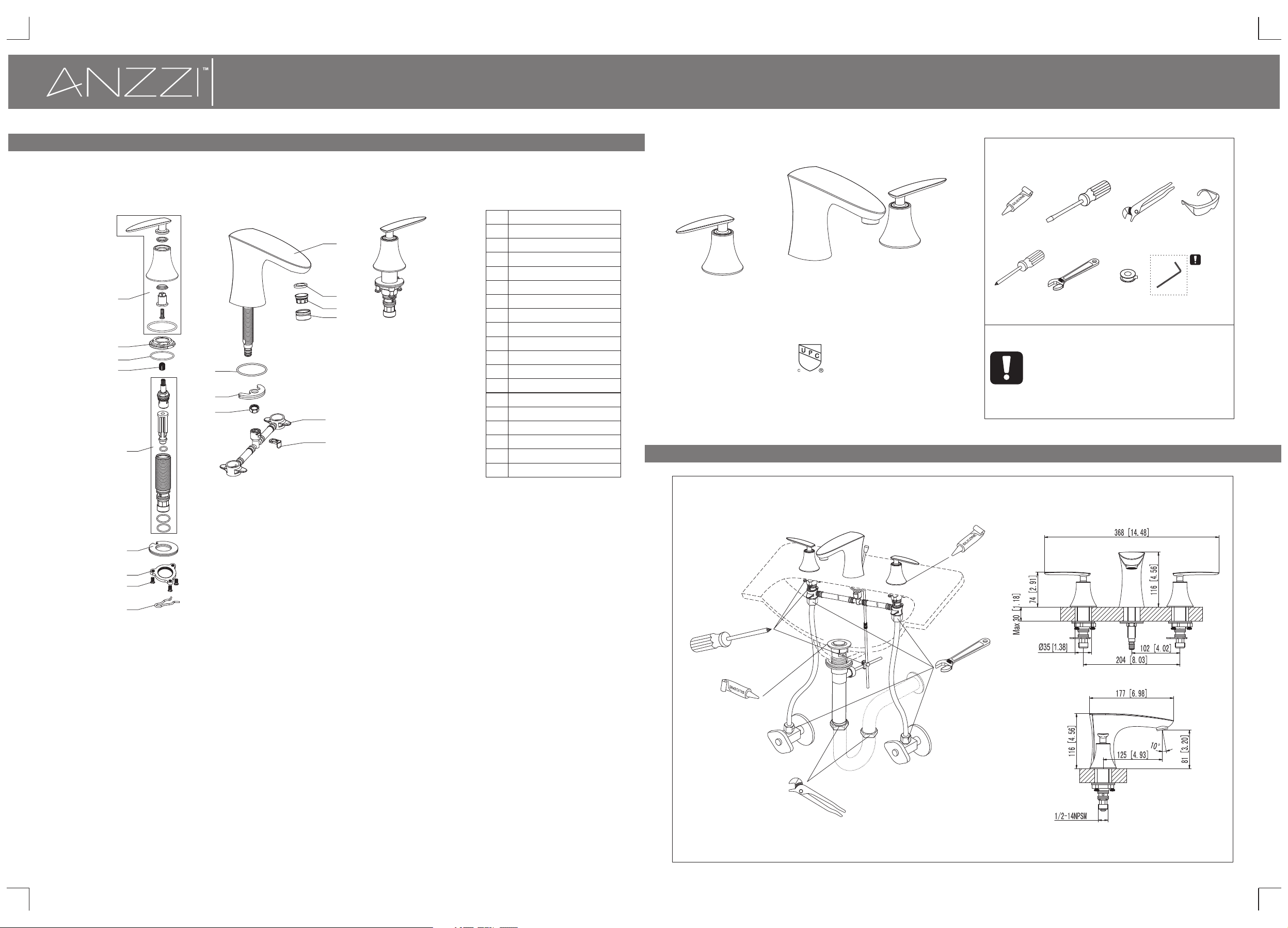
Step 4 Parts list
1
2
3
4
5
1-844-44-ANZ Z I o r v i sit www.ANZ Z I . c om
10
11
12
13
14
15
16
17
18
PA RT N A MENO .
Hand le as sem bly
1
Lock n ut
2
O-ri ng
3
Adap ter
4
Wat er va lve a sse mbl y
5
Gask et as sem bly
6
Lock n ut
7
Scre w
8
Clam p spr ing
9
Spou t
10
Aera tor w ash er
11
12
Aera tor c ore
13
Aera tor c oll ar
O-ri ng
14
Gask et as sem bly
15
Lock n ut
16
Flex ibl e hos e
17
Plas tic l ock r ing
18
WIDE SPREAD LAVATORY FAUCET
ASME A112.18.1/ CSA B1 25.1
The tools might be applied to the following places:
Silic on e
screwd riv er
INSTALL ATI ON MAN UAL
RECOMME NDED TOOLS
Scr ew K ni fe Chann el L oc ks
Adjustable Wrenc h
Attention:
for easy installation, you will need:
1.To read all the installation instruction completely before
beginning.
2.To read all the warning, attention and maitenance
information.
3.To purchase the proper supply lines.
Teflon ta pe
Allen k ey
Gog gl es
WARN ING:
Ple ase kee p the
too l for fut ure
use !
6
7
8
9
Page 2
Step 1 Faucet and pop-up installation
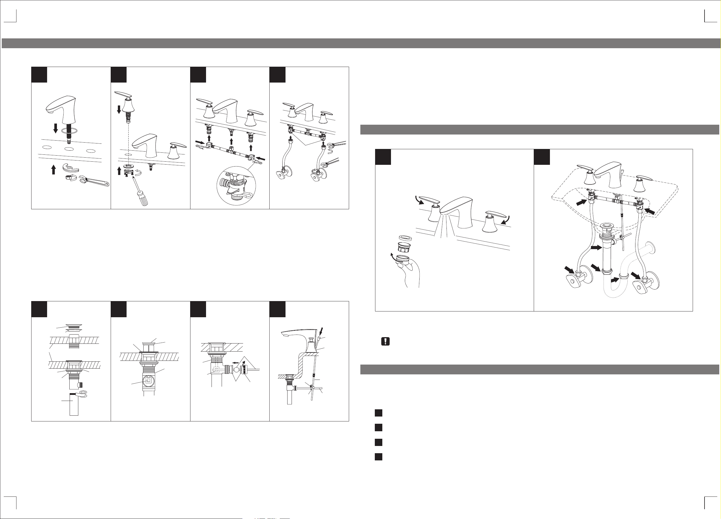
Faucet installation
1
2
3
4
4.Insert lift rod through hole on faucet body. Connect extend rod to lift rod. Attach horizontal rod to extend rod using
fittings, tighten screw.
Step 2 Checking and testing
1/2 ”(13 mm)I PS
HOT
COLD
WARNIN G:
DON'T O VE RT IG HT EN !
1.Posit ion the body with o-ring in t he insta llation surface as show n and secure it with gasket assembl y and tighten
the lock nu t with adjustable wrenc h.
2.Position the handle in installation surface as shown and secure it with fixing kit and tighten the screw with
screwdriver. Repeat the above steps for the other handle.
Caution: please be caution with the position of hot and cold handles.
3.Posit ion the as shown an d fix it to the faucet as shown w ith .flexibl e hose clamp spr ing
4.Conne ct the water supply lines t o faucet a nd water supply valve and t ighten it with wrench.
Warning: The water supply valve mentioned above are not included, please purchase them from plumbshop.
Pop-up installation
1
fla nge
top r ubber w asher
sin k base
was her
loc knut
tai lpiec e
dra in body
bot tom
rub ber
was her
2
fla nge
ali gn hole i n
dra in stop per
wit h guide r od
ope ning
(po inted t oward
bac k wall)
dra in stop per
o-r ing
sin k
dra in body
3 4
hor izont al rod
dra in body
dra in
sto pper
hol e
pla stic
gas ket
rod g uide nu t rod b all
scr ew
fitti ng s
lift ro d
fauce t
body
exten d ro d
horiz on ta l ro d
1
Remove th e aerator by hand. Turn the fa ucet han dle all the way on, turn on hot a nd cold water supply and fl ush
1.
2
water lin es for one minute. Reinst all aera tor by hand.
2.Check a ll connections at arrow s for leak s, re-tighten it if neces sary.
BUT DON 'T OVERTI GHTEN
Step 3 Cleaning and care
Daily cleaning and care are required in order to keep the product shining and
properly working.
1.Remove pop-up drain stopper, and flange with top rubber washer for pop-up assembly. Insert drain body from
underneath of sink drain hole. Replace flange and top rubber washer back to drain body. Tighten flange as far as
possible. Remove and put silicone along bottom of. (Optional) Slide bottom rubber washer on drain body up against
bottom of sink. Tighten washer and locknut firmly against base for tight seal. Remove tailpiece from drain body, add
Teflon tape, replace tailpiece.
2.Replace pop-up drain stopper to drain body with o-ring in place, and align stopper hole with guide rod opening.
3.Remove rod guide nut and rod ball plastic gasket. Insert horizontal rod into drain body and through hole in drain
stopper. Replace rod guide nut with rod ball plastic gasket and tighten it.
1
Clean it with water and dry it with soft cloth.
2
Clean the product with gentle liquid or glass cleaner.
Don't use acid cleaner.
3
Don't clean with abrasive material, abrasive paper or knife.
4
 Loading...