

Page 1

ANYWAVE
ATSC VHF III 500W PA
User Manual
Version 1.1 – July 2, 2019
Page 2

ACT-VHF-I-500PA User Manual
Copyright Notice
Copyright © Anywave Communication Technologies, Inc. 2019, All rights reserved.
No part of this publication may be reproduced, translated, transcribed, stored in a retrieval
system, or transmitted into any form or by any means, without the express written permission
of Anywave Communication Technologies, Inc.
FCC Compliance
Note: This equipment has been tested and found to comply with the limits for a Class A
digital device, pursuant to part 15 of the FCC Rules. These limits are designed to provide
reasonable protection against harmful interference when the equipment is operated in a
commercial environment. This equipment generates, uses, and can radiate radio frequency
energy and, if not installed and used in accordance with the instruction manual, may cause
harmful interference to radio communications. Operation of this equipment in a residential
area is likely to cause harmful interference in which case the user will be required to correct
the interference at his own expense
The antenna(s) used for this transmitter must be fixed-mounted on the outdoor permanent
structures. RF exposure compliance is addressed at the time of licensing, as required by the
responsible FCC Bureau(s), including antenna co-location requirements of §1.1307(b)(3).
Changes or modifications not expressly approved by Anywave Communication Technologies,
Inc. could void the user's authority to operate the equipment.
Disclaimer
Information provided by Anywave Communication Technologies is believed to be accurate
and complete; however, no liability can be assumed for its use.
The manufacturer makes no representations or warranties, either expressed or implied, by or
with respect to anything in this manual, and shall not be liable for any implied warranties of
fitness for a particular purpose or for any indirect, special, or consequential damages.
Information in this document is subject to change without notice and does not represent a
commitment on the part of the manufacturer.
USE OF THIS PRODUCT IN A MANNER OTHER THAN DESCRIBED IN THIS
MANUAL MAY RESULT IN DAMAGE TO THE EQUIPMENT AND/OR PERSONAL
INJURY.
ACT-VHF-I-500PA-USR-DOC-V1.1, 07/02/2019 Page 2 of 31
Page 3

ACT-VHF-I-500PA User Manual
PLEASE READ THIS MANUAL IN ITS ENTIRETY BEFORE ATTEMPTING TO
INSTALL THE EQUIPMENT. CONTACT ANYWAVE WITH ANY QUESTIONS OR
CONCERNS YOU MAY HAVE.
Unpacking
Carefully unpack the equipment and perform a visual inspection to determine if any apparent
damage has occurred during shipment. Please notify the delivery carrier and Anywave
immediately if shipment damage has occurred. Retain all original shipping materials.
Please locate and reference the Packing Check List to verify you have received all
components of your system. Retain the Packing Check List for future reference.
Also, please identify and remove all packing materials and supports (foam pads, etc.) prior to
initial turn on of the equipment.
Returns and Exchanges
Written approval and a Return Authorization Number (RAN) are required from Anywave for
all equipment returns. Please direct all return inquiries to the Anywave Service Department at
support_us@anywavecom.com, providing the Sales Order number and Serial Number(s) of
the equipment. Complete details regarding the nature and circumstances of your return must
be included in your RAN request. Proper handling and return shipping instructions will be
provided with an approved RAN number.
Technical Support
Technical support and troubleshooting assistance for Anywave Transmitters is available
through the Anywave Service Department during normal business hours (8:00 AM - 5:00 PM
CST) at (847) 415-2258. Email questions to support_us@anywavecom.com.
Note: For all service and support requests, you will need to provide the Serial Number of the
equipment with your Sales Order number. For future reference, please record that information
here: ________________________________________
Anywave Communication Technologies Inc.
300 Knightsbridge Parkway, Suite 150, Lincolnshire, IL 60069
Tel: (847) 415-2258
Fax: (847) 415-2112
http://www.anywavecom.net
ACT-VHF-I-500PA-USR-DOC-V1.1, 07/02/2019 Page 3 of 31
Page 4
ACT-VHF-I-500PA User Manual
WARNING
THE VOLTAGES, CURRENTS, AND RF ENERGY IN THIS EQUIPMENT ARE
DANGEROUS. PERSONNEL MUST AT ALL TIMES OBSERVE ALL SAFETY
WARNINGS, INSTRUCTIONS, AND REGULATIONS.
IN THE CASE OF EMERGENCY, ENSURE THAT ALL POWER HAS BEEN
DISCONNECTED.
ALWAYS DISCONNECT POWER BEFORE REMOVING COVERS,
ENCLOSURES, OR SHIELDS. DO NOT PERFROM SERVICE ON THE
EQUIPMENT WHEN ALONE OR FATIGUED. KNOW YOUR EQUIPMENT AND
DO NOT TAKE RISKS.
This manual is provided as a general guide for trained and qualified personnel well aware of
the dangers inherent in handling potentially hazardous electrical transmission equipment.
The installation, operation, maintenance and service of this equipment involves risks both to
personnel and equipment and must ONLY be performed by qualified personnel exercising
due care. Anywave Communication Technologies, Inc. shall not be responsible for injury or
damage resulting from improper handling or from the use of improperly trained or
inexperienced personnel performing such tasks.
All local building and electrical codes as well as fire protection standards must be observed in
the installation and operation of the equipment.
ACT-VHF-I-500PA-USR-DOC-V1.1, 07/02/2019 Page 4 of 31
Page 5

ACT-VHF-I-500PA User Manual
Contents
1 Product Appearance ........................................................................................ 6
1.1 Front Panel .................................................................................................................................... 6
1.2 Back Panel .................................................................................................................................... 8
2 Specifications .................................................................................................... 9
3 Control Interface ............................................................................................ 10
3.1 Local (Controller) Interface ........................................................................................................ 10
3.2 Web Interface .............................................................................................................................. 18
ACT-VHF-I-500PA-USR-DOC-V1.1, 07/02/2019 Page 5 of 31
Page 6

ACT-VHF-I-500PA User Manual
1 Product Appearance
1.1 Front Panel
LAN
Connector:10M/100M Ethernet
Note:Ethernet port for web-based remote control
(ipaddress: 192.168.1.210, username/password: anywavecom/anywavecom)
LED_PWR
Green light will be on when the DC voltage of internal power supply is within the normal range
(48 VDC ~ 52 VDC).
Green light will flash when the DC voltage of internal power supply is out of the normal range
(48 VDC ~ 52 VDC).
Green light will be off when the external power supply is turned off, or internal power supply
module does not work.
LED_RS485
Green light will flash once per second when the internal communication is normal.
Green light will stay constantly on or off when the internal communication is abnormal.
LED_FWD
Blue light will be on when RF_OUT has power output.
Blue light will be off when the RF button is turned off, or the PA enters the auto-protection mode
and therefore shuts down its RF output. There are several situations which will result in
auto-protection mode, such as the input power is too high, the reflected power is too high, or the
temperature is too high.
ACT-VHF-I-500PA-USR-DOC-V1.1, 07/02/2019 Page 6 of 31
Page 7

ACT-VHF-I-500PA User Manual
LED_ALARM
Red light will be off if there is no alarm.
Red light will be on if there is any alarm.
RESET: reserved.
Note:
1) The front fan covers can be removed to clean the air intake path. No screw driver is needed, and no
disassembly of the PA is required.
2) When a warning occurs and the PA enters auto-protection mode, the only way to clear this state is to
cycle power on the PA module once the problem(s) is resolved. Otherwise all warning LEDs will
remain on even if the problem(s) no longer exists.
ACT-VHF-I-500PA-USR-DOC-V1.1, 07/02/2019 Page 7 of 31
Page 8

ACT-VHF-I-500PA User Manual
1.2 Back Panel
RF IN
Connector: N
Impedance: 50 Ω
Note: If input power from RF_IN is lower than rated input value, the output power will be lower
than rated output power accordingly. This is because the PA has a fixed gain. If the input level
from RF_IN is higher than the rated value, it will result in RF output distortion and performance
deterioration. If the input level is more than 1 dB higher than the rated value or the output power
is higher than preset FWD threshold, it may trigger the current-limiting function. The PA will
enter the auto-protection mode, and there will be reduced RF output or even no RF output.
RF_OUT
Connector: 7/16 DIN
Impedance: 50 Ω
Note: RF_OUT must be connected with a load, otherwise the PA will enter the auto-protection
mode and there will be in no RF output.
RS485
Connector: DB9-M
Note: Connected to REMOTE (PRS-485-1) port of Controller, which is
used for control and communication between the Controller and
the PA.
AC INPUT: 176~300VAC, 47~63Hz, 16A/220VAC (single-phase, 3-wire – L1, L2, GND)
AC Power Breaker: ON/OFF
ACT-VHF-I-500PA-USR-DOC-V1.1, 07/02/2019 Page 8 of 31
Page 9

ACT-VHF-I-500PA User Manual
2 Specifications
Environment
Operation Temperature: -10 oC ~ +60 oC (+14 oF ~ +140 oF)
Operation Humidity: 20 % ~ 90 % (non-condensing)
Atmospheric Pressure: 86 kPa ~ 106 kPa
Power Supply
Voltage: 176 ~ 300 VAC (full load)
Frequency: 47 ~ 63 Hz
RF Performance
Frequency: 54 MHz ~ 88 MHz
VSWR: ≤ 1.5
Shoulder Level: ≥ 36dBc (with pre-correction ON)
Size: 480mm(W)*222mm(H)*423mm(L)
Note
1) The electrical interface characteristics are measured at rated power. Values may change.
2) Operating in abnormal conditions may result in damage to the equipment. Long operating hours in
severe environments may reduce the reliability of the entire system, which may cause permanent
damage to equipment. Make sure all electrical interface characteristics and environmental parameters
are within the defined range listed above before operating this equipment.
ACT-VHF-I-500PA-USR-DOC-V1.1, 07/02/2019 Page 9 of 31
Page 10

ACT-VHF-I-500PA User Manual
3 Control Interface
3.1 Local (Controller) Interface
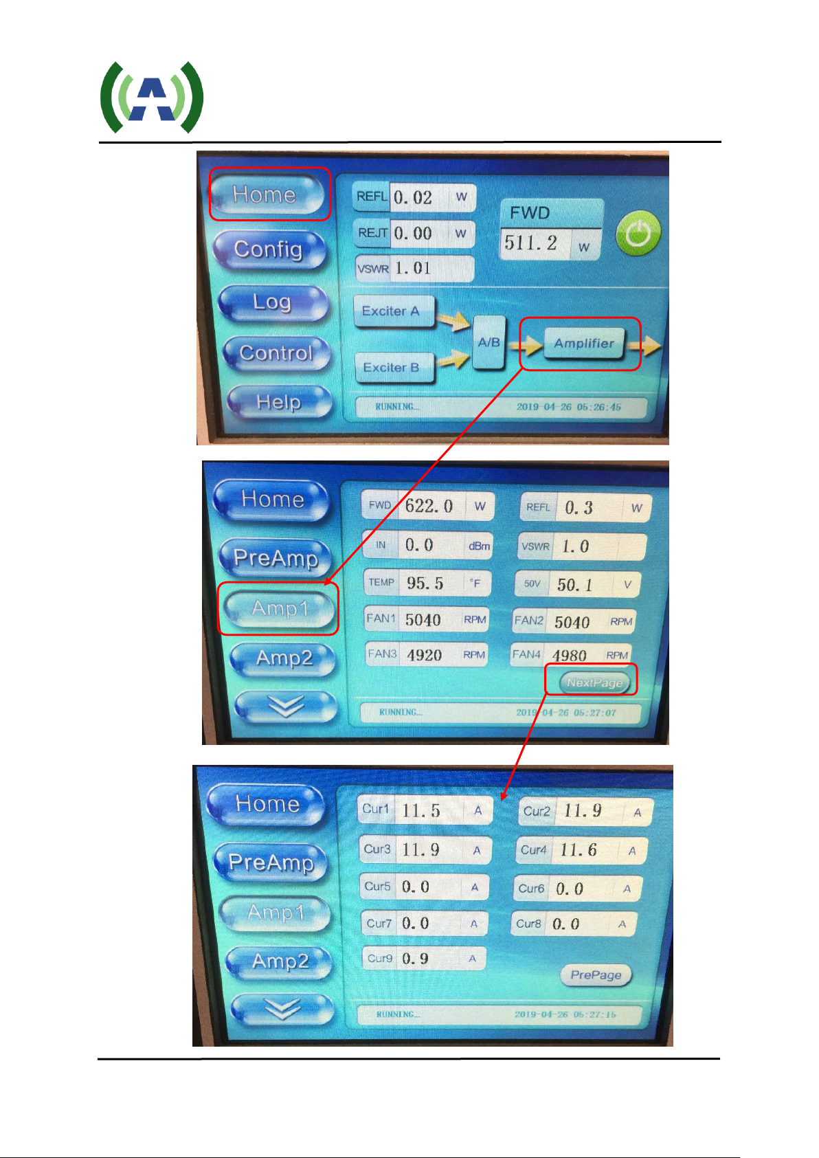
Local control and monitoring of the PA unit can be accomplished via the Controller touch panel interface.
Use a standard serial cable to connect the PA DB9 RS485 port to the Controller PRS-485-1 RS485 port
(please reference the 500W VI TX QSG for the system interconnect diagram and details). With this
connection established, the PA information will be displayed on the Controller touch screen and web
interface, as shown below:
Note: The displayed settings and numbers contained in the screens below are for illustration purposes only
and may be different from those in actual use.
ACT-VHF-I-500PA-USR-DOC-V1.1, 07/02/2019 Page 10 of 31
Page 11
ACT-VHF-I-500PA User Manual
ACT-VHF-I-500PA-USR-DOC-V1.1, 07/02/2019 Page 11 of 31
Page 12

ACT-VHF-I-500PA User Manual
ACT-VHF-I-500PA-USR-DOC-V1.1, 07/02/2019 Page 12 of 31
Page 13

ACT-VHF-I-500PA User Manual
ACT-VHF-I-500PA-USR-DOC-V1.1, 07/02/2019 Page 13 of 31
Page 14

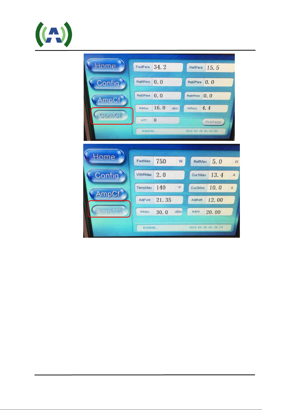
When press the
AmpCf (Amplifier
Configuration)
Button, you will be
prompted to enter
Password: 27654
ACT-VHF-I-500PA-USR-DOC-V1.1, 07/02/2019 Page 14 of 31
ACT-VHF-I-500PA User Manual
Page 15
ACT-VHF-I-500PA User Manual
ACT-VHF-I-500PA-USR-DOC-V1.1, 07/02/2019 Page 15 of 31
Page 16

ACT-VHF-I-500PA User Manual
ACT-VHF-I-500PA-USR-DOC-V1.1, 07/02/2019 Page 16 of 31
Page 17

ACT-VHF-I-500PA User Manual
ACT-VHF-I-500PA-USR-DOC-V1.1, 07/02/2019 Page 17 of 31
Page 18
ACT-VHF-I-500PA User Manual
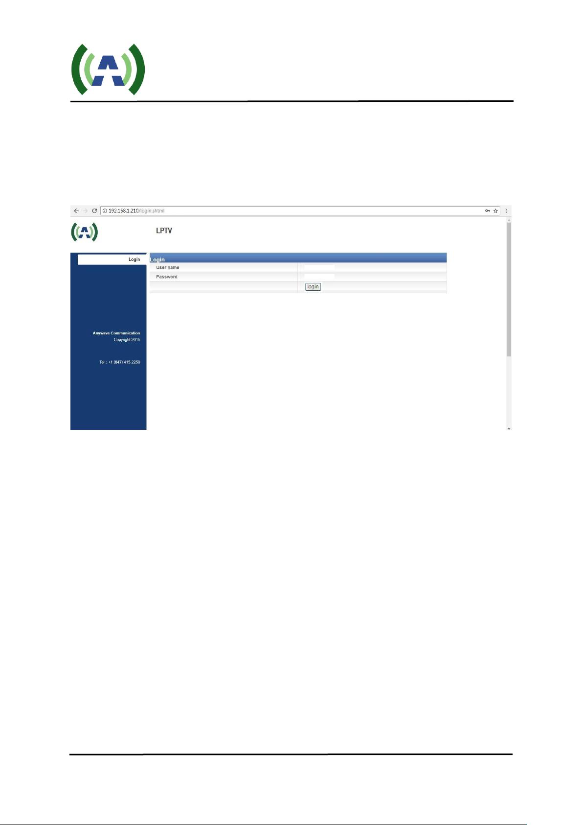
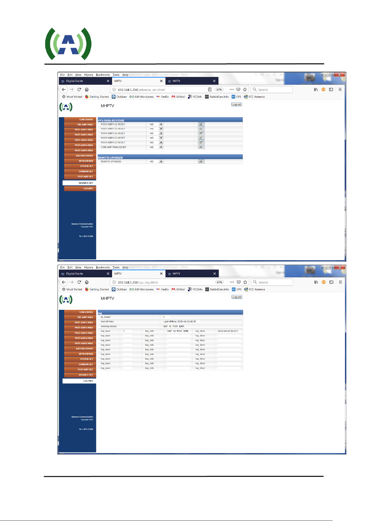
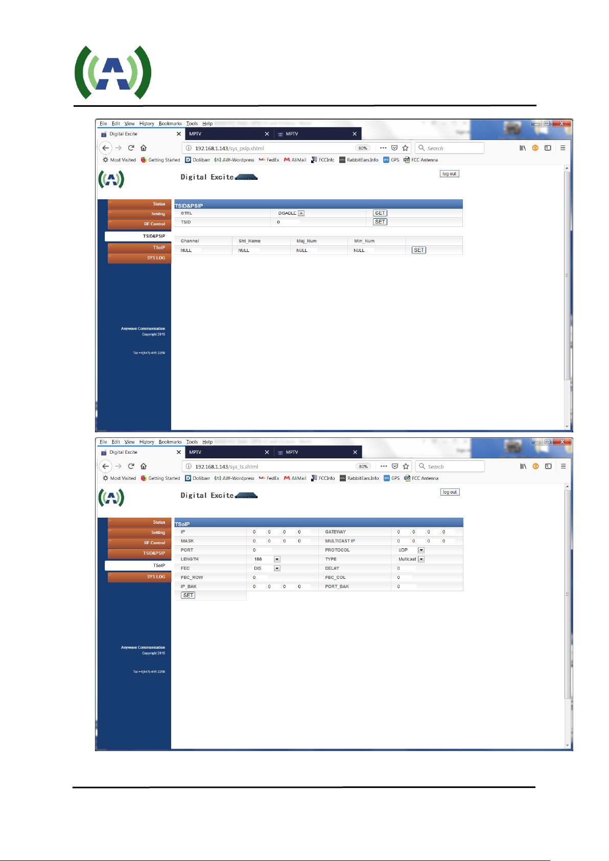
3.2 Web Interface
The 500W PA, Controller, and Exciter all have built-in web interfaces for system monitoring and control.
Below are screenshots of the PA (192.168.1.200), Controller (192.168.1.210), and Exciter (192.168.1.143)
web interfaces. Enter the IP address of the equipment in a web browser's address bar to cause a login
window to pop up.
The “admin” tier provides full status and control of the equipment and is accessed with a username and
password of "anywavecom" and "anywavecom" (case sensitive).
ACT-VHF-I-500PA-USR-DOC-V1.1, 07/02/2019 Page 18 of 31
Page 19

ACT-VHF-I-500PA User Manual
Controller web pages:
ACT-VHF-I-500PA-USR-DOC-V1.1, 07/02/2019 Page 19 of 31
Page 20

ACT-VHF-I-500PA User Manual
ACT-VHF-I-500PA-USR-DOC-V1.1, 07/02/2019 Page 20 of 31
Page 21

ACT-VHF-I-500PA User Manual
ACT-VHF-I-500PA-USR-DOC-V1.1, 07/02/2019 Page 21 of 31
Page 22

ACT-VHF-I-500PA User Manual
ACT-VHF-I-500PA-USR-DOC-V1.1, 07/02/2019 Page 22 of 31
Page 23
ACT-VHF-I-500PA User Manual
ACT-VHF-I-500PA-USR-DOC-V1.1, 07/02/2019 Page 23 of 31
Page 24

PA web pages:
ACT-VHF-I-500PA User Manual
ACT-VHF-I-500PA-USR-DOC-V1.1, 07/02/2019 Page 24 of 31
Page 25

ACT-VHF-I-500PA User Manual
ACT-VHF-I-500PA-USR-DOC-V1.1, 07/02/2019 Page 25 of 31
Page 26

ACT-VHF-I-500PA User Manual
ACT-VHF-I-500PA-USR-DOC-V1.1, 07/02/2019 Page 26 of 31
Page 27

Exciter web pages:
ACT-VHF-I-500PA User Manual
ACT-VHF-I-500PA-USR-DOC-V1.1, 07/02/2019 Page 27 of 31
Page 28

ACT-VHF-I-500PA User Manual
ACT-VHF-I-500PA-USR-DOC-V1.1, 07/02/2019 Page 28 of 31
Page 29
ACT-VHF-I-500PA User Manual
ACT-VHF-I-500PA-USR-DOC-V1.1, 07/02/2019 Page 29 of 31
Page 30

ACT-VHF-I-500PA User Manual
ACT-VHF-I-500PA-USR-DOC-V1.1, 07/02/2019 Page 30 of 31
Page 31

ACT-VHF-I-500PA User Manual
Anywave Communication Technologies Inc.
300 Knightsbridge Parkway, Suite 150, Lincolnshire, IL 60069
Tel: (847) 415-2258
Fax: (847) 415-2112
Email: sales_us@anywavecom.com
http://www.anywavecom.net/
ACT-VHF-I-500PA-USR-DOC-V1.1, 07/02/2019 Page 31 of 31
 Loading...