

Page 1

OW N ER ’S MAN UAL
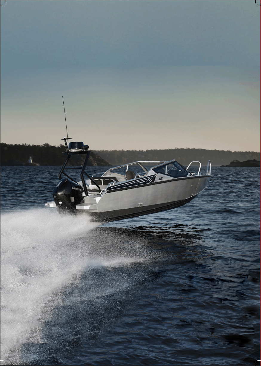
AN Y TE C A 2 1
Page 2
Page 3

Anytec A21
Owner’s Manual
Date of issue: 2019-02-15
Anytec Sweden AB, Magasinsgatan 7,
SE-903 27 Umeå, Sweden
[email protected] www.anytec.se
Page 4

Page 5

TABLE OF CONTENTS
WELCOME ABOARD .....................................................................1
1. INTRODUCTION ........................................................................3
1.1 ABOUT THIS OWNER’S MANUAL ...................................................................3
1.2 GENERAL DESCRIPTION
1.3 CRAFT IDENTIFICATION NUMBER (CIN)
1.4 EXPLANATION OF SAFETY LABELS
1.5 DEALER RESPONSIBILITIES
1.6 WARRANTY
1.7 INSURANCE
............................................................................................................6
............................................................................................................ 6
1.8 SECURMARK ANTI-THEFT MARKING AND TRACKING SYSTEM
2. OPERATING THE BOAT .............................................................7
2.1 SAFETY ROUTINES BEFORE LEAVING SHORE ...........................................7
2.1.1 Weather and forecast ...............................................................................................................7
2.1.2 Loading
2.1.3 Passengers
2.1.4 Fuel
2.1.5 Engine
2.1.6 Fastening of objects and closing of doors and hatches
2.1.7 Nautical charts
2.1.8 Safety check of the boat
2.1.9 Inform about your route
2.1.10 Safety equipment
2.2 EMERGENCY ENGINE SHUTDOWN SWITCH ...........................................9
2.3 MAN-OVERBOARD PREVENTION AND RECOVERY
2.4 FIRE PREVENTION
2.4.1 Fire extinguisher ...................................................................................................................... 10
2.4.2 Fire port
2.4.3 Refuelling...................................................................................................................................12
2.4.4 Webasto heater, optional equipment (diesel fuel)
2.5 STARTING THE BOAT ....................................................................................... 14
2.5.1 Starting the engine ................................................................................................................. 14
2.5.2 After starting the engine
2.5.3 Leaving shore
2.6 OPERATING THE BOAT AT SEA ..................................................................... 15
2.6.1 Trim of boat pitch (longitudinal angle) .............................................................................. 16
.........................................................................................................................................7
...................................................................................................................................7
................................................................................................................................................7
...........................................................................................................................................7
...........................................................................................................................8
............................................................................................. 10
.....................................................................................................................................12
........................................................................................................................... 14
...................................................................................4
...................................................4
...............................................................5
................................................................................5
........6
...................................................7
..........................................................................................................8
..........................................................................................................8
....................................................................................................................8
................................9
.......................................................... 13
....................................................................................................... 14
Page 6

2.6.2 Trim of the boat roll (transverse movement) ...................................................................18
2.7 RISK OF CARBON MONOXIDE ACCUMULATION................................ 20
2.8 ANCHORING, MOORING AND TOWING
2.9 LIFE RAFT STORAGE AREAS
........................................................................... 24
................................................ 21
3. GENERAL INFORMATION ......................................................25
3.1 BASIC BOAT DIMENSIONS & SPECIFICATIONS ...................................... 25
3.2 DESIGN CATEGORIES
3.3 ENGINE REQUIREMENTS
3.4 VESSEL STABILITY AND BUOYANCY
3.5 LOAD CAPACITY / CE SIGN
3.6 PASSENGER LOCATIONS AND EMBARKING/DISEMBARKING
3.7 SAFETY LABEL LOCATIONS
3.8 BOAT LAYOUT
3.8.1 Boat layout, Standard equipment ....................................................................................... 33
3.8.2 Boat layout, optional equipment
.................................................................................................... 33
3.9 STORAGE AREAS ................................................................................................ 35
3.10 THRU HULL LOCATIONS
3.11 DASH LAYOUT (STANDARD AND OPTIONAL EQUIPMENT)
3.11.1 Dash layout ............................................................................................................................37
3.11.2 Dash switch panel................................................................................................................38
3.12 TRAILERING ....................................................................................................... 38
3.13 STRONG POINTS
3.14 LIFTING OF THE BOAT
...................................................................................... 26
................................................................................ 27
........................................................... 28
.......................................................................... 28
......... 29
........................................................................... 31
......................................................................................... 34
............................................................................. 36
......... 37
............................................................................................. 39
.................................................................................. 40
4. SYSTEMS & COMPONENTS ...................................................43
4.1 FUEL SYSTEM ....................................................................................................... 43
4.1.1 Fuel tank ................................................................................................................................... 44
4.1.2 Filling the tank
4.1.3 Phase separation
4.1.4 Fuel lter
4.2 STEERING SYSTEM ............................................................................................. 45
4.3 NAVIGATION LIGHTS
4.4 BILGE PUMPS
4.5 SIMRAD® MULTIFUNCTION DISPLAY & NAVIGATION SYSTEM
4.6 ENGINE CONTROLS AND INSTRUMENTATION
4.7 LECTROTAB TRIM SYSTEM
4.8 SWIM LADDER / MOB RESCUE LADDER................................................... 51
4.9 WINDSHIELD WIPERS
4.10 CANOPY
......................................................................................................................... 44
.....................................................................................................................44
................................................................................................................................... 44
...................................................................................... 46
....................................................................................................... 46
...... 48
................................... 50
.............................................................................. 51
....................................................................................... 52
............................................................................................................. 52
Page 7

4.10.1 Canopy congurations ........................................................................................................53
4.10.2 How to install, remove and store the canopy
............................................................... 53
4.11 ADJUSTABLE SEATS, DRIVER AND NAVIGATOR ................................... 54
4.12 WATERSPORT TOW ROPE ATTACHMENT
4.13 WEBASTO HEATER (OPTIONAL)
............................................................... 55
4.14 AUDIO & RADIO SYSTEM (OPTIONAL)
4.15 COCKPIT TABLE (OPTIONAL)
.................................................................... 56
4.16 CAMERA WITH INFRARED (OPTIONAL)
4.17 SEARCHLIGHT (OPTIONAL)
4.18 VHF RADIO (OPTIONAL)
....................................................................... 57
.............................................................................. 58
.............................................. 54
.................................................. 56
................................................ 57
5. ELECTRICAL SYSTEMS ...........................................................59
5.1 GENERAL DESCRIPTION ................................................................................ 59
5.2 BATTERIES & CHARGING
5.3 BATTERY SELECTOR SWITCH
5.4 CIRCUIT AND MAIN BREAKER PANEL
5.5 ELECTRICAL SCHEMATICS
............................................................................... 60
....................................................................... 60
....................................................... 61
............................................................................. 62
6. MAINTENANCE ........................................................................63
6.1 FUEL SYSTEM ....................................................................................................... 64
6.2 HULL, DECK, RAILS & SUPERSTRUCTURES
6.2.1 Aluminum treatment M-400® maintenance & principle ............................................ 65
6.2.2 Hull below water, anti-fouling treatment
6.2.3 Anodes for prevention of galvanic corrosion
..........................................................................65
6.3. COMPONENT MAINTENANCE ................................................................... 67
6.3.1 Stainless steel ...........................................................................................................................67
6.3.2 Cushions
6.3.3 Canopy
6.3.4 Tempered glass windows
6.3.5 Fender list
6.3.6 Plastic panels............................................................................................................................69
6.3.7 Hinges and latches
6.3.8 MOB rescue & swim ladder
6.3.9 Painted surfaces
.................................................................................................................................... 68
.......................................................................................................................................68
....................................................................................................... 69
.................................................................................................................................69
................................................................................................................. 69
................................................................................................ 70
...................................................................................................................... 70
6.4 WINTER STORAGE/ SPRING PREPARATIONS .......................................... 70
6.4.1 Measures before winter storage ......................................................................................... 70
6.4.2 Measures after winter storage
............................................................................................ 71
6.5 SPARE PARTS & SERVICE ................................................................................... 72
............................................... 64
.................................................................... 66
7. ATTACHMENTS .........................................................................73
Page 8

Page 9
WELCOME ABOARD
WE WOULD LIKE TO congratulate you on the purchase of your new boat and thank you
for the faith you have placed in the dealer and Anytec.
We stand behind every boat we build with pride of craftsmanship and always strive to
deliver the best boats available in our market segment. Anytec boats are always built to be
extremely durable and have absolute top-class handling characteristics. An Anytec is built
to be driven.
This Owner’s Manual is intended to help you become familiar with your new boat.
Your Anytec dealer will be happy to help you to maintain your boat and answer questions
concerning operation, maintenance, warranty, performance, accessories, parts and service.
Information and assistance is also available via our website www.anytec.se.
Enjoy your boating. Enjoy Anytec. See you at sea!
Information in this publication is based upon the latest production specications available at printing. Anytec® reserves the right to make changes at any time, without notice, in the colors, equip-
ment, specications, materials and prices of all models, or to discontinue models. Should changes
in production models be made, Anytec ® is not obligated to make similar changes or modications
to models sold prior to the date of such changes.
WELCOME ABOARD__PAGE 1
Page 10
WELCOME ABOARD__PAGE 2
Page 11

1. INTRODUCTION
1.1 ABOut this OWnER’s MAnuAL
The purpose of this owner’s manual is to help you to use your boat in a safe and enjoyable
way. The manual includes detailed information about the boat, its equipment and accessories, as well as instructions for use and correct maintenance of the boat. Please read the
manual carefully and familiarise yourself with your boat before using it.
At Anytec, we believe that you shall be free to choose a suitable outboard engine for your
specic needs. For this reason, the boat manual cannot be very detailed on engine related
topics. Often, a reference to the engine manual or other specialised components is made.
We advise you to read the engine and engine instrumentation manuals carefully, and do not
hesitate to ask for help from experts.
Likewise, the boat may have been customised or modied by another party than Anytec,
either when new or later in its lifetime. This manual alone may not be enough If your boat
deviates from the data, standard equipment and optional equipment specied in this manual. Please consult the party who modied the boat and any manuals provided by them.
The owner’s manual alone is not a sufcient source of information on seamanship and
boating safety. If this is your rst boat or the boat type is not familiar to you, ensure your
safety and comfort by obtaining sufcient experience in handling and using the boat before
you assume the responsibilities of the boat master. Your boat dealer, local boating clubs and
national motor boat and sailing associations will provide you with more information about
local training in boating and will be able to recommend qualied instructors.
In some countries, operation of the craft may require a permit or authorisation, and special
regulations may apply. Your boat may also have to be registered with the proper navigation
authorities. A Declaration of Conformity is part of the documents that you receive with
the boat and it must be kept aboard with other ofcial documents at all times, and may be
mandatory when registering the boat.
This owner’s manual is not a detailed service and troubleshooting guide. In case of prob-
lems please contact your local Anytec dealer. Modications that affect the safety features
of the boat are to be performed only with the builder’s written authorisation. The builder
assumes no responsibility for unauthorised modications. Always keep your boat in good
condition and make allowance for the deterioration that may occur over time. Be careful
to observe any signs of wear caused by age, heavy use or abuse. Any boat, no matter how
strong it is, may sustain severe damage if used inappropriately.
Always adjust the speed and the heading of your boat to suit the prevailing sea conditions.
Make sure the forecasted wind and sea conditions match the design category of your boat
and that you and your crew can navigate the boat in the conditions that may arise. Wind
and sea conditions for design category C range from storm to strong wind with a danger
of unusual waves and gusts.These are dangerous conditions that necessitate a skilled and
t crew and a well-maintained boat.
1. INTRODUCTION__PAGE 3
Page 12
If your craft is equipped with a life raft, study its instructions carefully. The boat must be
equipped with the appropriate safety equipment (life vests, safety harnesses, etc.) as required for the boat type and the weather conditions. In some countries, this equipment
is compulsory. The crew must be familiar with the correct use and operation of all safety
equipment and be able to handle the boat in emergencies (including rescuing a person who
has fallen overboard, towing, etc.). Yachting schools and clubs arrange rescue training and
practice opportunities on a regular basis.
Everyone aboard the craft should wear a suitable personal otation device (life vest or
boating vest). Cold waters quickly reduce the ability to swim and climb onboard, so fast
assistance is crucial. Please note that in some countries national boating regulations may
require everyone aboard to wear a personal otation device whenever on board.
Finally, please pay respect to the environment by complying with good practice as well as
local, national and international (Marpol) regulations. Thank you!
1.2 GEnERAL DEsCRiptiOn
The boat is primarily intended for private and leisure use. The boat has a bow cockpit and
a stern cockpit. The stern cockpit can be covered by a canopy and closed by a front door.
The boat is of single hull type entirely made of aluminum, so are the handrails and cleats.
The boat is designed and built according to the standards for CE approval in category C
and is designed to be propelled by a single outboard engine.
1.3 CRAft iDEntifiCAtiOn nuMBER (Cin)
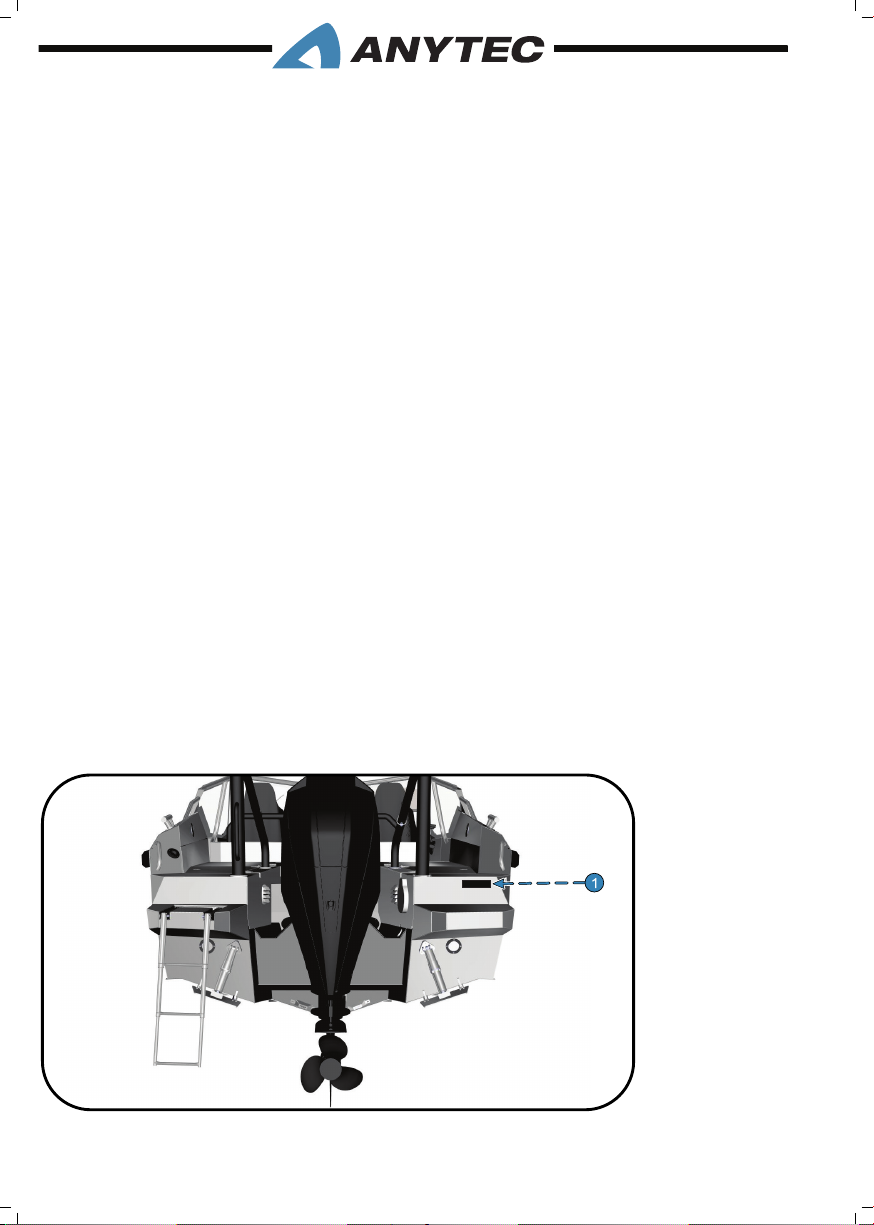
The starboard stern storage engraves the Craft Identication Number. All correspondence
related to the boat must include the CIN.
1. CIN location
1. INTRODUCTION__PAGE 4
Page 13
1.4 ExpLAnAtiOn Of sAfEty LABELs
The labels that advise the owner/operator regarding necessary safety precautions are
mounted at the key locations of your boat (refer chapter 3.7 to learn their location). These
safety precautions should be followed while operating/servicing the equipment and hence
are duplicated in this manual. These precautions are not all-inclusive. Always follow the
recommended instructions given in this manual while operating your boat.
• Do not remove or obstruct any safety label.
• Replace the labels which become illegible; you can obtain this replacement by calling
your dealer.
This manual includes labels explained to highlight particularly important topics. They are
divided into 4 different categories as explained below:
DANGER—Immediate hazards will result in severe personal injury or death if the warning is
ignored.
WARNING—Hazards or unsafe practices which can result in personal injury or death if the
warning is ignored.
CAUTION—Hazards or unsafe practices which may result in personal injury, product or property
damage if the warning is ignored.
NOTE— Provides information which is important to make proper operation or maintenance.
1.5 DEALER REspOnsiBiLitiEs
In addition to a pre-delivery check and service of the boat, your dealer is to provide:
• A description and demonstration of the safety systems, features, instruments and
controls on your boat
• An orientation in the general operation of your boat
• A review of all warranty information and how to obtain warranty service
• The Owner Information Package
If you do not receive all of these, or have any questions, contact your dealer.
1. INTRODUCTION__PAGE 5
Page 14

1.6 WARRAnty
The dealer who has sold you the boat gives information regarding product warranty, terms
and conditions. If for some reason such information is not provided, or any of the below
steps fail, contact Anytec..
Registration
The boat must be registered to ensure correct warranty management. Please contact the
dealer from whom you have purchased the boat. If that is not possible, please contact Anytec Sweden or any Anytec dealer.
Transfer of Warranty
Please contact the dealer from whom you purchased the boat to arrange the transfer.
1.7 insuRAnCE
Boat insurance is mandatory in many countries. We recommend you to contact a trusted
insurance company in your country before you own the boat.
1.8 sECuRMARk Anti-thEft MARkinG AnD tRACkinG systEM
Your boat has a unique code number sprayed in different places of your boat: to prevent
theft, and locate the boats after a theft. It is visible through special tools used by the authorities. The code is added at the factory and enables them to access the boat and owner
details from a database.
The SecurMark system requires a subscription and Anytec pre-pays it for the rst 12
months after you register your ownership details. We encourage you to activate Secur-
Mark and continue the subscription after the rst 12 months of free service. You may also
mark and register your engine. Ask your dealer for help to register and provide further
information if needed. Anytec bag provides the printed info from SecurMark.
1. INTRODUCTION__PAGE 6
Page 15
2. OPERATING THE BOAT
Before operating the boat for the rst time, make sure that you read and understand the operation
and safety topics given in owner’s manual.
2.1 sAfEty ROutinEs BEfORE LEAvinG shORE
Familiarise yourself with this owner’s manual. Always check the following items before
leaving the shore:
2.1.1 Weather and forecast
Consider the wind, waves and visibility. Are the design category, size and equipment of your
boat, as well as the skills of the skipper and crew, sufcient for going to the water?
In strong winds and rough seas all portholes, doors, hatches and vents must be closed to
prevent water from getting into/onto the boat.
2.1.2 Loading
Do not overload the boat, distribute the loads appropriately. For stability: do not place
heavy loads high up (refer to chapter 3.3, 3.4 and 3.5). You can always check the CE-plate
for maximum allowed loading.
2.1.3 Passengers
Ensure that there are life jackets for everybody on board and instruct passengers to be
seated while the boat is in motion. Refer chapter 3.6 for the location of passengers. Make
sure all members of the crew understand their specic tasks, before leaving the shore. It is
recommended that at least 2 passengers can operate the boat.
2.1.4 Fuel
Check that there is enough fuel, plus a reserve tank for harsh weather etc. Look for any
fuel leaks.
2.1.5 Engine
Check the functioning and condition of steering, electrical equipment and batteries, also
carry out the routine checks specied in the engine instructions handbook.
2.1.6 Fastening of objects and closing of doors and hatches
Make sure everything on board is secured appropriately (preferably stored in the hatches)
in the event of high winds, fast maneuverers and rough seas. Check that the deck drains
are not blocked. Close and secure hatches to avoid water ingress.
2. OPERATING THE BOAT__PAGE 7
Page 16

2.1.7 Nautical charts
While navigating on unfamiliar waters, ensure that you have nautical charts covering a suf-
ciently large area. Even if you are having a chart plotter, you should carry regular charts
onboard. There is always a risk for technical malfunction of electronic devices; therefore,
regular charts are also important.
2.1.8 Safety check of the boat
• Check that hatches are closed and watertight.
• Ventilate the stern sofa storage where batteries are installed. Ventilate the bow sofa
storage where the Webasto fuel tank (optional) is installed; to remove any gases or
fumes.
• Make sure that at least one person onboard knows the location of the reghting
equipment.
• Check that bilge water is at minimum, and the electrical pump is working (manual
operation).
• Check the navigation lights, if you expect darkness.
• Check for any leakage of water into the boat/fuel from tanks/fuel lines.
2.1.9 Inform about your route
Always inform someone on the shore about your planned route, to enable fast support in
case of problems.
2.1.10 Safety equipment
The sea can be unpredictable. Be prepared by carrying the following equipment, as a minimum, at all times:
• Life jackets for each person onboard
• Appropriate weatherproof clothing
• Compass
• Charts (printed)
• Anchor and line
• Towing and mooring ropes
• First-aid kit and thermal blanket
• Bucket
• Emergency ares/signals
2. OPERATING THE BOAT__PAGE 8
Page 17
• VHF radio and water protected GSM phone (subject to coverage)
1
1
• Binoculars
• Knife (to cut tangled ropes)
• Drinking water
2.2 EMERGEnCy EnGinE shutDOWn sWitCh
An engine shutdown safety switch is built into the engine control; it incorporates a shutoff switch and a lanyard. Before operating the boat, connect one end of the lanyard to the
shut-off switch while the other end to the operator.
If the engine needs an urgent shut down: pull the lanyard cord to release it from the shutoff switch, which in turn shuts down the engine. This switch is designed to shut the engine
off when the boat operator leaves the control station, either accidentally by falling into the
boat, or by being ejected overboard.
The lanyard should be long enough to prevent unintentional activation. Do not let the
lanyard become entangled and replace it if worn.
Wear the lanyard at all times while operating the boat. Use it to stop only in an emergency. DO
NOT use it to shut off the engine during normal operation.
2.3 MAn-OvERBOARD pREvEntiOn AnD RECOvERy
Other areas must not be occupied when underway, due to the risk of falling potentially into
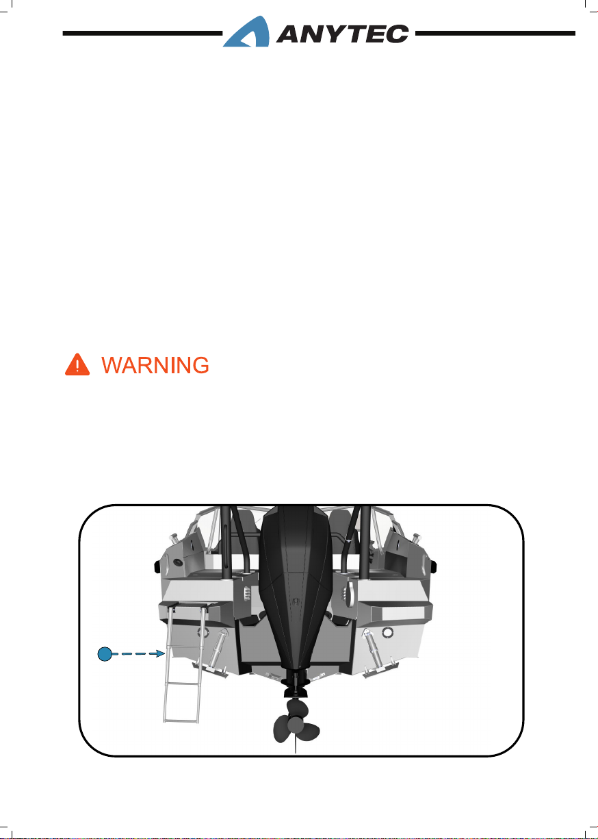
the water. If a person has fallen into the water in calm seas, the person can use the rescue
ladder located on the stern platform, refer gure below.
1. Safety Ladder
2. OPERATING THE BOAT__PAGE 9
Page 18
Always turn off the engine and activate the emergency (dead-man) switch before using the ladder.
The ladder can be pulled down by a person already in the water. In harsh weather, or if the person
is physically not able to climb, it may be hard to use the ladder alone and help from a person onboard may be needed. Therefore, it is recommended for two persons onboard, especially during
harsh weather conditions.
Chapter 4.8 further describes MOB rescue/swim ladder.
A rotating propeller can be harmful for a swimmer or person who has fallen overboard, or a person using the ladder to board the boat or to enter the water. Shut down the engine and activate
the emergency switch (dead man’s switch) if there is any person in the water behind the engine,
and always before using the ladder.
2.4 fiRE pREvEntiOn
Fire is a serious boating hazard; because boats burn quickly. Do not remain onboard and
ght a re for longer. If the re is out of control and cannot be put out with the re suppression equipment onboard, abandon the ship immediately.
It is the ultimate responsibility of the boat owner to inspect and maintain the boat’s re
prevention and re-ghting equipment. This chapter covers re prevention and ghting
measures related to the fuel-driven systems onboard the boat. For details of each system/
component, please refer to their specic chapters (e.g. chapter on stove, heater and fuel
tank).
2.4.1 Fire extinguisher
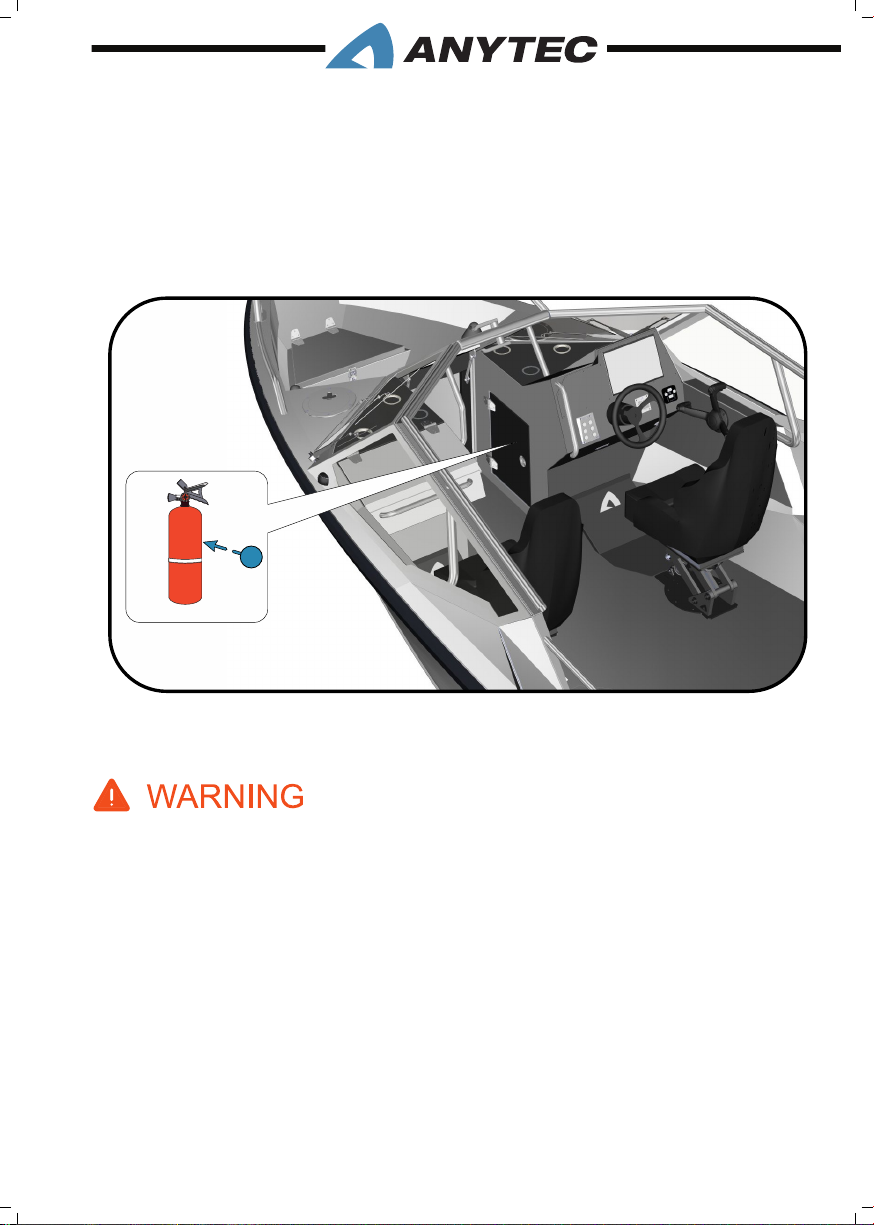
The re extinguisher is located inside the starboard pulpit, behind the door. A safety label
is attached on the pulpit to show the location. Make sure you know how to remove it and
use it.
The boat, when in service, shall always be equipped with the following portable re extinguisher class:
Fire rating: 13A 89B C with a minimum of 2 kg capacity.
The boat owner/operator should:
1. Check the re-ghting equipment at regular intervals; indicated on the equipment.
2. Replace portable re extinguisher equipment, if expired or discharged, with devices
of same re-ghting capacity.
3. Ensure that the re-ghting equipment is readily accessible when the boat is occu-
pied.
2. OPERATING THE BOAT__PAGE 10
Page 19
1
1
1
1
4. Inform the crew members and passengers about the location and operation of the
re-ghting equipment, the re port, escape routes and exits.
5. Unlock any deck hatches to enable reghting inside storage areas and keep the
re port free.
6. Keep the bilges clean and check for fuel and gas vapors or fuel leaks frequently.
1. Fire Extinguisher
Never obstruct passageways to exits/hatches, safety controls (fuel valves, LPG valves, electrical
switches, etc.), portable re extinguishers and re ports; never allow unqualied personnel to
modify any of the boat’s systems. Have the re-ghting equipment checked at the intervals indicat-
ed on the equipment.
2. OPERATING THE BOAT__PAGE 11
Page 20
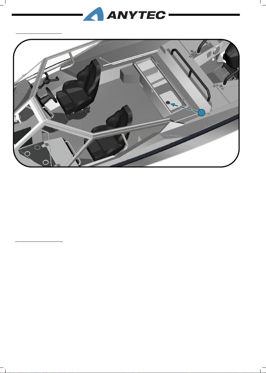
2.4.2 Fire port
1
1
1. Fire port
The stern cockpit U-sofa storage is equipped with a re port. The port makes it possible to
detect and ght a re below deck (bilge/tank area). The access to the re port is through
the U-sofa central hatch. The re port location is shown on the below gure. It has a
transparent cover, and an opening suitable for the re extinguisher nozzle. In case of re
inside the bilge/ below deck area, introduce the nozzle to the re port opening and activate
the extinguisher. Replace the re port if worn or damaged.
2.4.3 Refueling
Before you start to ll the engine fuel tank, turn off the engine and naturally any cigarettes or any other open ames like stoves, candles or lamps with
ames. It is not allowed to use switches or appliances that can cause spark
formation during fueling.
When lling the fuel tank, do not use a plastic funnel between the fuel gun or fuel container and the boat, as it prevents discharging the electric charge difference between the fuel
pistol and the lling tting and could cause a spark.
Always clean up any spillage immediately after fueling.
Loose reserve fuel containers onboard, should be stored in one of the stern storages
behind the canopy garage (not the stern sofas in the cockpit!). They are ventilated and
drained. Bow sofa-storages can also be used; they are ventilated but not drained. Always
check fuel containers before each trip to detect leakages or smell of fumes.
2. OPERATING THE BOAT__PAGE 12
Page 21
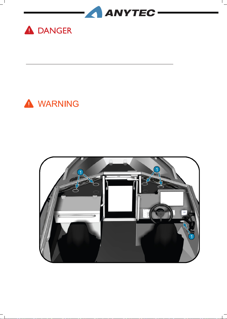
Fuel and its vapors are highly explosive. Exercise extreme caution and follow these instructions
while refueling. The smell of fuel always means that there is vaporised fuel in the boat. Never store
fuel close to electric circuits or batteries. Do not use plastic funnels when fueling.
2.4.4 Webasto heater, optional equipment (diesel fuel)
The heater is installed below the starboard helm, and is connected directly to a separate
10L diesel fuel tank located in the storage below the portside pulpit. It draws cool air
under the helm, and releases hot air at the base of the windows and below the helm (see
gure). It can be overheated or damaged if air vents are blocked.
Do not plug or block any air outlets and inlets of the heater system. It can cause re when the
heater is in use. Always ll the diesel tank outside of the boat (refer chapter 4.16). Read the Webas-
to owner’s manual carefully as it includes further instructions and warnings. Anytec recommends
checking all the air and fuel connections for leaks each season..
To inspect the heater and its connections, open the storage door below the starboard pulpit and
look to the top of the storage room.
1. Hot air outlets
For complete instructions on operation and maintenance, refer to the separate
OEM owner’s manual that was developed specically for this equipment. It is provided with the Anytec document bag
2. OPERATING THE BOAT__PAGE 13
Page 22

2.5 stARtinG thE BOAt
2.5.1 Starting the engine
• Read the engine owner’s manual carefully, as the boat may be equipped with several
engine brands and models.
• Ensure that there are no fuel or oil leaks in or around the engine.
• Check that the main power switch is turned on (for location and function, see
chapter 5.4).
• Make sure the engine gear shift is in the neutral position (propeller will not rotate
when engine starts) and that the engine propeller is submerged properly in water,
away from any objects or persons.
• Start the engine according to the manufacturer’s owner’s manual. If the engine does
not start, or function poorly, check for instructions in the manual. If unsuccessful,
contact your engine dealer (in most cases it is your Anytec dealer).
2.5.2 After starting the engine
(visible just below the engine hood, well above water level). If water does not ow out
after start, Check the cooling water control beam, to ensure that the cooling system is
working properly (visible just below the engine hood, well above water level). If water does
not ow out after start, then engine overheating can cause severe engine damage.
Your engine is equipped with visual and sonic alarms for critical malfunctions such as overheating. Read the engine manual to understand these alarms. If alarm goes off, turn off the
engine immediately and check the possible reason as per the manual. Contact the nearest
Engine/Anytec dealer if the problem continues.
Do not turn off the main power switch while the engine is running and ensure that no exhaust
fumes get inside the boat or endanger others.
2.5.3 Leaving shore
The crew releases each mooring rope etc. as per your instructions. Make sure mooring
ropes or other ropes does not tangle with the propeller.
Ask crew to be seated as soon as possible after leaving mooring position. For seating positions refer chapter 3.6.
2. OPERATING THE BOAT__PAGE 14
Page 23

The emergency shutdown switch
Attach the lanyard of the emergency switch (refer chapter 2.2) to your hand or foot, im-
mediately after loosening the mooring ropes. More specic instructions can be found in
the engine manual. Especially when you are driving the boat alone it is crucial that the boat
stops if you fall overboard or stumble on board.
Remember to unfasten the lanyard from your hand before coming ashore or moving around
in the boat. If not, an abrupt engine stop will occur and may cause fast boat movements.
2.6 OpERAtinG thE BOAt At sEA
Learn the seafaring rules and the COLREG provisions (International Regulations for Preventing Collisions at Sea) and follow them. Navigate with care
and make sure your charts are up to date. Boating regulations are available in
bookstores or from local authorities. Always adapt your speed to the prevailing
conditions, your skills and the environment.
This owner’s manual is not a manual on good seamanship. The operator is always responsible to ensure that he/she has the right skills to operate a boat. Therefore, this manual does
not substitute a course (or similar extensive experience) in boating and seamanship. Always take proper training if you lack such, or in any way feel insecure on boat handling and
seamanship. Operating a boat can often be more demanding than driving for instance a car.
• Always make sure that the boat and safety equipment is in a good and safe condition.
• Always maintain an unobstructed view of the area around the boat to detect the
dangers such as other boats or oating objects in your course, shallow waters or
challenging water and weather conditions
• The view forward may be obstructed when the boat is passing the planing speed,
as the bow raise. This may also happen in certain load and trim conditions. Be extra
careful.
• Always adjust the speed and trim to the prevailing conditions. Be particularly careful
when driving at high speeds and waves. For instance, a low bow in high waves or a
tailwind may cause the bow to plunge into waves and ll the boat with water or may
cause sharp and sudden direction changes.
• Sharp turns, a too low bow or sideways waves at high speeds may be very dangerous
due to the risk of fast changes of directions causing passengers and the operator to
shift and loose grip, potentially be hurt or lose control of the boat.
2. OPERATING THE BOAT__PAGE 15
Page 24
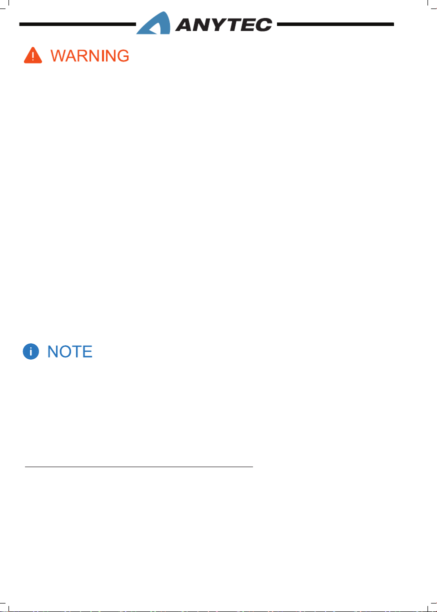
1. Adjust the engine trim and the trim system with care – at high speed they radically
change the behavior of the craft. Do not operate this craft with engine trim at
negative angles (boat bow pushed down) or with the trim system set at a roll (boat
leaning sideways) at high speeds. Craft may lean over on side or dive/plunge into
waves. Instability in turns may result.
2. Waves impair handling. Reduce the speed in rough seas.
3. Do not operate at high speed while in congested high trafc water ways or in
weather and sea condition of reduced visibility, high winds or large waves. Observe
and obey speed limit and no wake zones.
4. Handling is impaired as speed increases. Rapid turns can lead to loss of control.
Slow down before sharp turns in either direction. Avoid rapid movements while
driving at high speeds, in high waves and at strong winds.
5. Never operate the boat if the engine rated power exceeds the maximum recommended power.
6. Do not sit in the bow area (in front of cockpit) when the boat is moving at speeds
higher than approximately 10 knots, or in conditions with high waves. Sudden boat
movements may cause injuries.
7. Always use the Emergency Engine Shutdown Switch when operating the boat.
1. “Ensure sufcient seamanship and operator training as mentioned in introduction”,
this book is not a training book for good seamanship”.
2. The International Regulations for Preventing Collisions at Sea (COLREG) and the
rules of the road require that a proper lookout be maintained at all times and ob-
servance of right of way be respected. Always be certain to have sufcient distance
to stop or maneuver if required to avoid collisions.
2.6.1 Trim of boat pitch (longitudinal angle)
The outboard engine has a built-in trim function which adjusts the angle of the engine
versus the transom. Refer chapter 4.6.
2. OPERATING THE BOAT__PAGE 16
Page 25
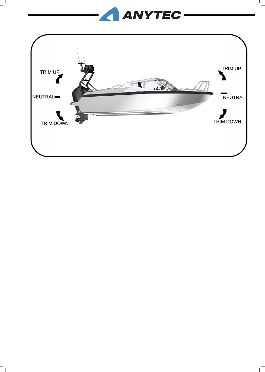
The engine trim is used to adjust the bow up or down (the so-called pitch) while the boat
1
is under speed. A well-adjusted engine trim will maximize safety and comfort, and will
minimize fuel consumption.
Mastering the trim requires some practice so if you are uncertain, ask someone experienced for help. Correct trim is very important for a safe, comfortable and fuel economic
ride, and for fast acceleration.
The basic directions to nd optimal trim are as follows, and shall be done during at water
conditions:
Accelerate to planing speed (approximately 10 to 15 knots depending on conditions):
• Engine trim is used to help the boat accelerate as fast as possible from zero to planing
speed, with an optimal pitch. Fast acceleration to planing saves fuel and improves the
view.
• Engine trim shall be at maximum trim down position directly at the start.
• As the boat accelerates and reaches planing speed, the trim is changed from the trim
down up to neutral trim, to keep the bow level or at a slight upward angle. Failure to
do so causes the bow to plough deep into the water, preventing the boat to pick up
speed and run safely.
2. OPERATING THE BOAT__PAGE 17
Page 26

Trim when running at speeds above planing
• When the boat is running at speeds above planing, the trim also needs to be adjusted.
As speed, direction, load, wind or wave condition changes, new adjustments may be
needed.
• Use the trim up, to lift the bow up slowly without change of throttle position.
Follow the log to notice for how long the speed is increasing. When the speed is not
increasing anymore, the trim is in the most fuel-economic position. Then lower the
bow slightly to avoid the propeller loose grip.
• In head sea (boat running against waves), you may have to use the trim to lower the
bow down to soften the vertical motions but be careful not to lower it too much
due to the risk of a bow to plunge into waves.
• In the following sea, you may instead need to raise the bow up to prevent nose-diving.
• A safe ride is always more important than maximising speed/fuel consumption, so
always trim for safety rst.
Trim when lowering speed to below planing:
When you reduce speed below planing, or stop the boat completely, the trim should again
be adjusted to trim down position. This improves manoeuvrability and makes the boat
ready to accelerate fast next time.
2.6.2 Trim of the boat roll (transverse movement)
The boat is equipped with 2 Trim Tabs and a control unit for these (Refer chapter 4.7).
Trim tabs can help you control and adjust the boat’s roll (transverse movement). The boat’s
roll is affected by wind direction, wave direction, speed and how the boat is loaded. Heavy
crosswind usually affects the boat the most.
By pushing down the trim tabs in the water, the hull resistance increases, and the bow is
pushed downwards. By just pushing down one of the trim tabs, the boat can roll in the
desired direction. The trim tab is used mostly to compensate for crosswind or unevenly
distributed load, and thus avoid the boat tilting sideways.
The trim tabs can also be used to press down the bow in the water (the boat’s attack
angle), but usually, it is faster and sufcient to use the engine trim for this (Refer chapter
2.6.1). However, the trim tabs can be used to adjust the angle of attack on a longer journey
under the same conditions, e.g. If you have much cargo in the bow. Fuel consumption may
then be lower than using the engine trim. A rule of thumb is “big adjustments or long time
with trim tabs, small adjustments or short time with the engine trim”.
2. OPERATING THE BOAT__PAGE 18
Page 27
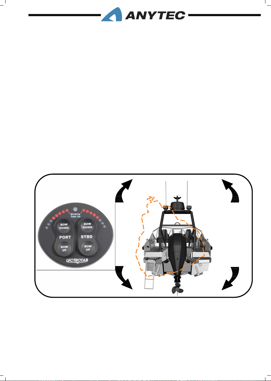
Learning to handle trim tabs in a good way requires some practice, so if you are unsure,
1
you should ask someone who has experience for help. Proper trimming is essential for a
safe, comfortable and fuel-efcient ride. Always proceed from a neutral position (trim tabs
postponed) and then adjust a little at a time until the correct effect is reached.
Trim tabs are very useful, but it is important to understand their major impact on boat’s
sea properties. Incorrect use can seriously affect the boat’s performance and driving characteristics, and cause an accident. Be careful and remember that these basic instructions
are not a substitute for good seamanship and experience. Please read the manual carefully
and contact your dealer or an experienced boat driver if you need further assistance.
The trim tabs are controlled from a control panel mounted on the starboard side of the
steering wheel, see below gure.
When the boat’s battery switch is switched on, the trim tabs are automatically calibrated
and positioned in a fully up-angled position. In this mode, the boat has its basic handling
characteristics and is not affected by the trim tabs. When the engine is turned off, the trim
tabs also returns to fully-angled position. Read the Lectrotab Manual for best understanding.
2. OPERATING THE BOAT__PAGE 19
Page 28
2.7 Risk Of CARBOn MOnOxiDE ACCuMuLAtiOn
Carbon Monoxide can accumulate in dangerous concentrations anywhere in or around
your boat including on back decks, swim platforms, or in water around generator exhausts.
CO can remain in or around your boat at dangerous levels even if your engine is no longer
running.
To minimize the risk of Carbon Monoxide poisoning, consider the following:
• Make sure that there is good ventilation throughout the boat. This is particularly
important when operating engine, stove or heaters that consumes oxygen and create
fumes / CO.
• Never operate the engine with the canopy enclosed unless there is ventilation
throughout the boat (i.e. forward and aft canvas panels are opened to allow air ow
through the boat).
• Make sure that the air inlets on the cockpit side panels are open when the canopy is
in use. They are supplied with fresh air from the outside air inlets.
• Never operate the boat with the canopy on and only the cockpit entry door opened.
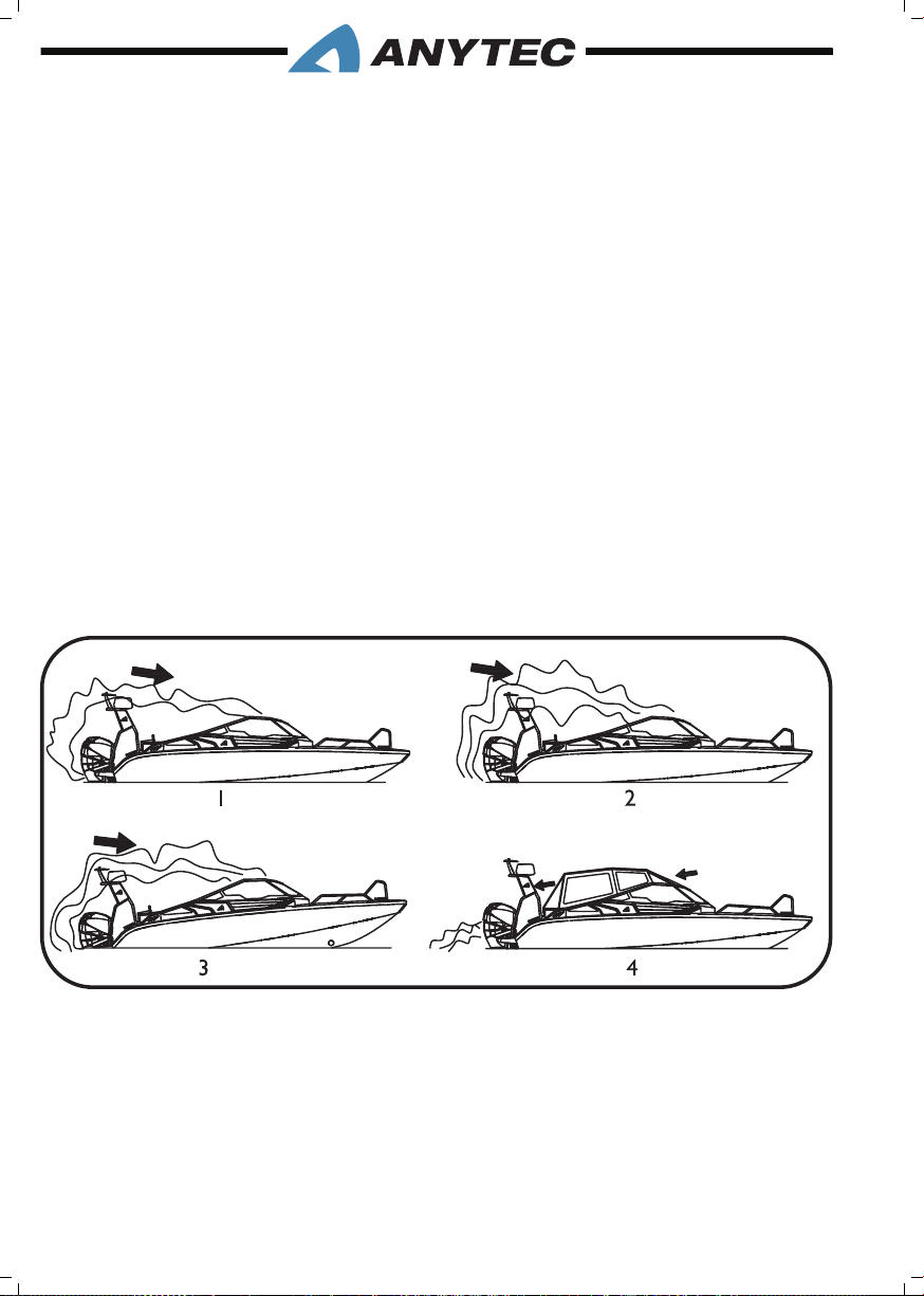
Accumulation of Carbon Monoxide Examples
Principal gure only
1. Wind blowing exhaust towards boat occupants
2. Operating at slow speed or dead in the water
3. Operating with “bow high”
4. Good air ow – open front and rear openings to let fresh air circulate
2. OPERATING THE BOAT__PAGE 20
Page 29
Fumes from the engine, heater, stove and other equipment that burns fuel contains Carbon Monoxide (CO) can kill you. Doors, air inlets and canopy ventilations/removable must be opened to
allow fresh air to circulate. Study this chapter carefully.
2.8 AnChORinG, MOORinG AnD tOWinG
Mooring, anchoring and towing require specic skills and good seamanship. Always ask for
advice when needed.
It is the owner’s and operator’s responsibility to ensure that mooring, towing and anchor
ropes, anchor chains and anchors are appropriate for the vessel’s intended use and in good
condition. Wear and impact of knots should be taken into consideration. Also refer chapter
3.13 (strong points)
Mooring:
When coming ashore or mooring to a quay the boat must be properly secured. The
boat, when moored, should withstand high winds and rough seas. The boat should not be
moored with temporary fastenings if the crew is not nearby. Make sure other boats are not
damaged by your boat and consider the effect of the wake of passing vessels.
Mooring ropes should be long enough and as horizontal as possible. The boat should be
able to rise and sway without moving sideways. You normally need two mooring ropes for
both bow and stern. Only use the strong point cleats, not the stem eye or secure eye. The
ropes for the bow should be equipped with elastic shock absorbers and the ropes for the
stem should be about the length of the boat. The points of contact between the rope and
the clasps should be checked regularly for wear and tear.
Moor your boat carefully, even in sheltered places, because weather conditions can change
rapidly. Do not moor the boat with the stern facing the open sea, because high waves could
ood the boat and sink it. Use loose fenders between the boat hull and any close objects
such as other boats when there is a risk of contact.
If the boat is left unattended, turn off the electric power using the main power switch (for
location and function, refer chapter 5.3).
Never leave your boat unattended for long periods. Observe the oating position of the
boat so that the water line is at a normal level. Check for any water in the bilge. If large
volumes of water accumulate in the bilge or at deck (for instance due to leakage, broken
bilge pump, lack of electric power, ooding or blocked deck drains), the boat may be seriously damaged or sink as the deck drain system may not work as intended.
2. OPERATING THE BOAT__PAGE 21
Page 30
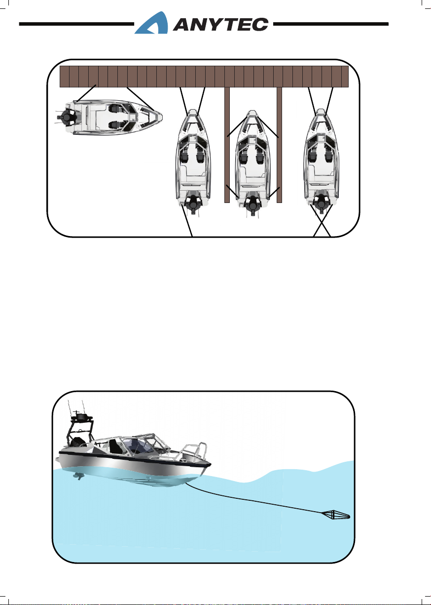
Examples of different types of mooring
Anchoring:
When you anchor or land temporarily in a natural harbor, ensure enough water depth.
Drop the anchor at a sufcient distance from shore, allowing time for the anchor to drop
and grip and to release enough anchor rope/chain. The anchor rope/chain length should
be at least 4-5 times the water depth. Choosing the right type of anchor and anchoring
method requires boating experience, ask for advice when needed.
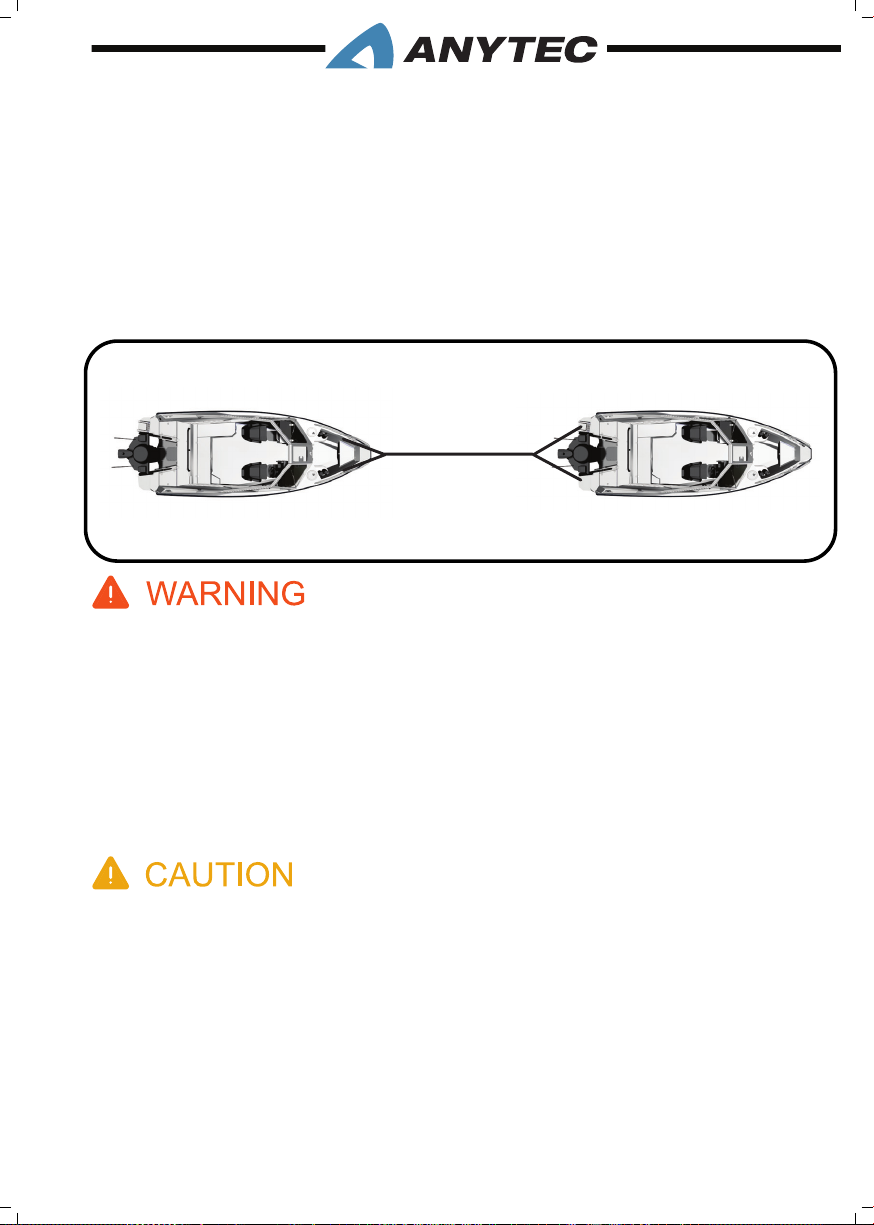
Storm anchor:
If you lose engine power at sea and waves are strong, keep the boat headed into the waves
by rigging a sea anchor off the bow (below principal gure). If there is no sea anchor on
board, use a canvas bucket or any object that will offer resistance.
2. OPERATING THE BOAT__PAGE 22
Page 31
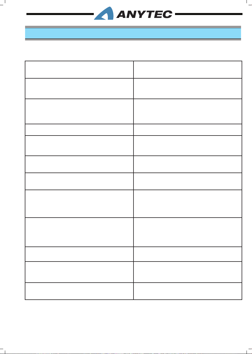
Towing:
Towing of boats is a very demanding and risky operation, requiring specic skills and experience. If possible use a professional towing company. If you have to tow or be towed on
your own, be very careful and operate at very low speed.
If you tow another boat, use strong, oating towing rope. Begin by towing very carefully,
avoiding twitches, and do not overload the engine. Adjust the length of the rope so that the
boat can be steered in all situations. Boat’s stability can be reduced when towing. Owners/
operators should also consider what action will be necessary when securing a tow line
on board.
1. Do not stop the boat by hand and don’t put your hand or foot between the boat and the
quay, bank, or another boat. Practice landing in good condition, use engine power moderately
but not tentatively.
2. Towing or being towed can lead to fatigue of the boat’s hardware and lines. Failure of any part
can seriously injure people or damage the boat. Do not stand directly in line with the tow
line. If the line were to break, it would “snap back” causing injury or damage to everything
in its path.
3. It is the owner’s/operator’s responsibility to ensure that mooring lines, towing lines, securing
straps, anchor chains, anchor lines, anchors and methods used are adequate for the boat and
situation.
1. Always tow or be towed at a low speed. Never exceed the hull speed of a displacement craft
when being towed. A tow line shall always be made fast in such a way that it can be released
or cut off when under load.
2. Always take possible changes in wind direction and the rise and fall of the water level, as well
as the wake of other boats, into proper account.
3. Breaking strength of ropes and chains must not exceed 80 % of the breaking strength of the
strong point in question. See chapter about strong points
4. Never leave your boat unattended for long periods. Observe the oating position regularly
and ensure that the bilge pump empties the bilge. Water accumulation in the bilge or at deck
by may cause severe damage.
2. OPERATING THE BOAT__PAGE 23
Page 32

2.9 LifE RAft stORAGE AREAs
The boat is not supplied with a life raft. You should choose to equip the boat with a life
raft, it can be installed either on the stern targa (if weather-proof) or be stowed in the
stern sofa.
Most life rafts can be delivered with an installation kit, such as brackets for horizontal or
vertical installation. There are many life raft types and manufacturers. Always consult experts on life rafts to choose the most suitable type and installation method. Please note
that the boat weight and load gures do not include the weight of a life raft, so that it
would reduce the load capacity.
3. GENERAL INFORMATION__PAGE 24
Page 33
3. GENERAL INFORMATION
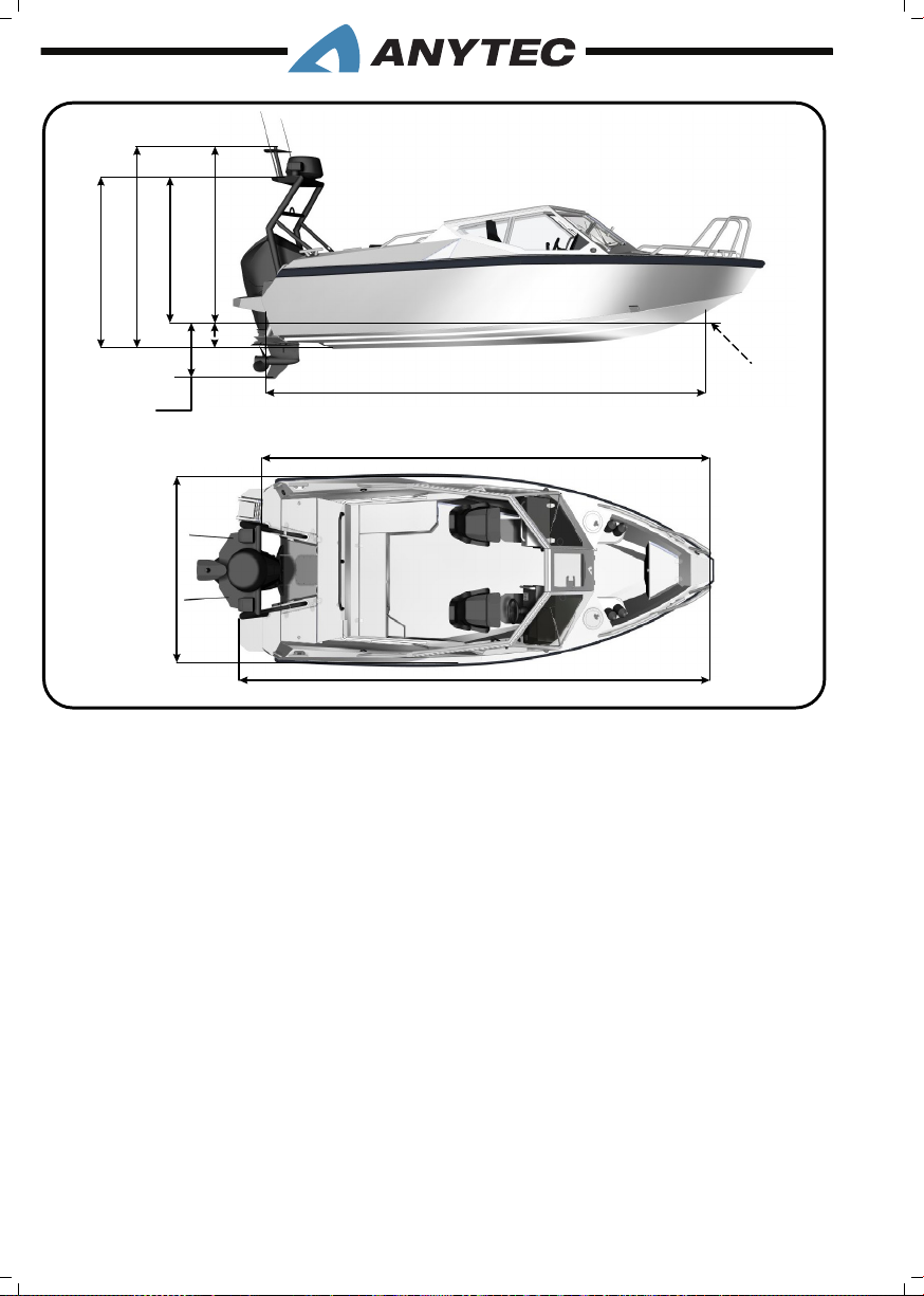
3.1 BAsiC BOAt DiMEnsiOns & spECifiCAtiOns
Length Over All, LOA 6670 mm
Length Water Line, LWL 5260 mm
Draft, Maximum with full load and largest
engine, Tmax
Beam Maximum, Bmax 2320 mm
Free Height, water level to top lantern, Ha1770 mm
Weight, empty boat without engine, mLT 1156 kg
Weight, empty boat with engine, mLCC 1423 kg
Weight Trailering, for trailering and lifting
(boat, engine, fuel, Anytec standard and
optional equipment, liquids) , mT
Weight Maximum (boat, engine, fuel, Anytec standard and optional equipment, liquids, crew, maximum luggage), mLDC
Maximum Crew (including driver), CL 6 persons
Engine Limitations Single outboard, max 200 hp / 147 kW.
900 mm
1635 kg
2085 kg
Maximum engine weight 267 kg.
Fuel capacity, built-in tank 170 liters
3. GENERAL INFORMATION__PAGE 25
Page 34
2200
1770
2650
2220
450
900
526 0
6240
2400
6670
WL
3.2 DEsiGn CAtEGORiEs
There are four design categories of boats based upon their ability to withstand wind and
water conditions; this boat is designed under Category C.
Category A – Designed for winds that may exceed wind force 8 (Beaufort scale – 40
knots) and a signicant wave height of 4m and above.
Category B -- Designed for winds that include up to wind force 8 (Beaufort scale – 40
knots) and signicant wave height up to and including 4m.
Category C – Designed for winds that include up to a wind force 6 (Beaufort
scale – 27 knots) and a signicant wave height up to and including 2m.
Category D – Designed for winds that include up to a wind force 4 (Beaufort scale – 16
knots) and a signicant wave height up to and including 0.3m, with occasional waves of
0.5m maximum height.
3. GENERAL INFORMATION__PAGE 26
Page 35
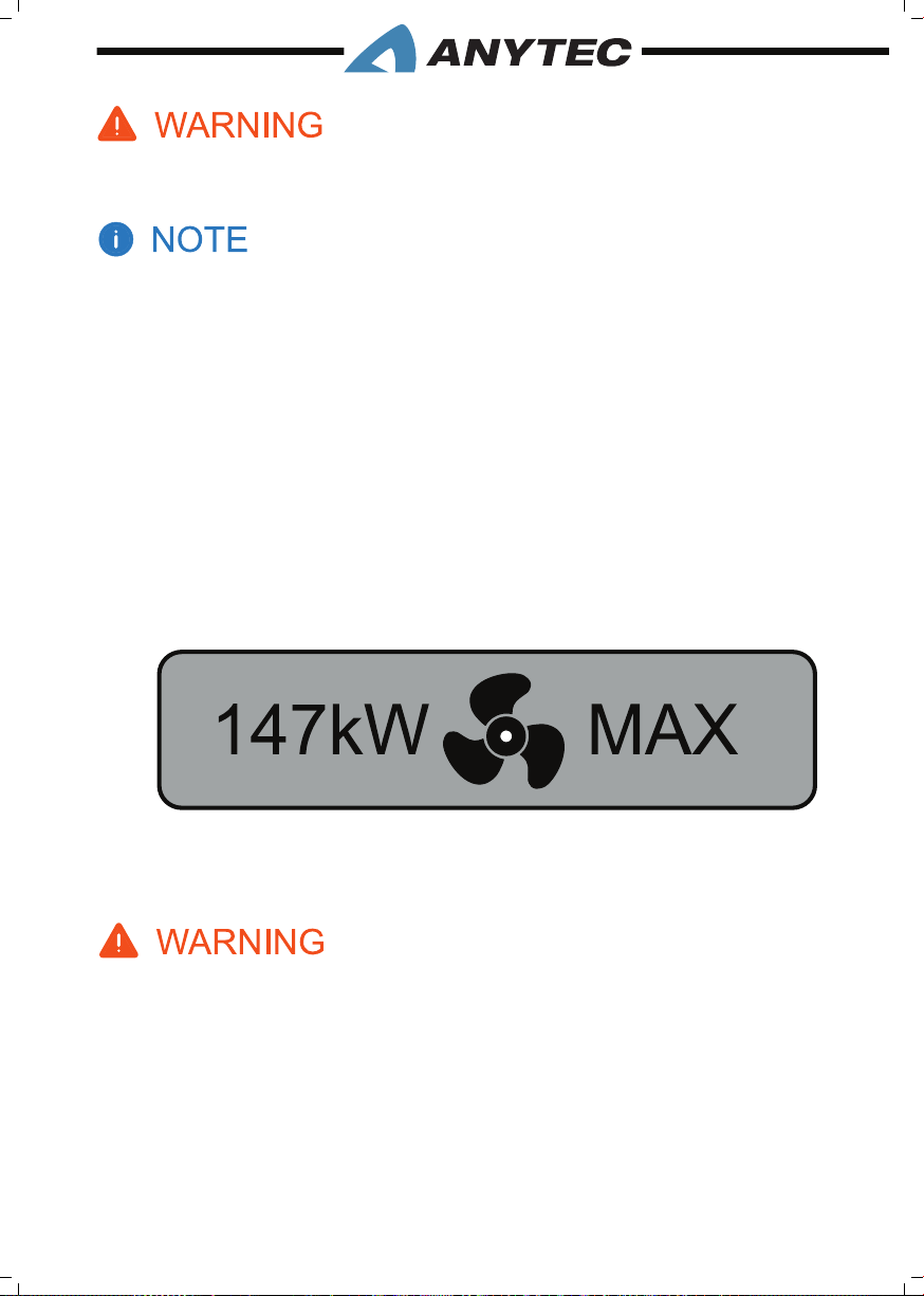
Do not attempt to boat in severe weather conditions. Death or serious injury can occur. Get to
shore before the weather turns bad.
The signicant wave height is the mean height of the highest 1/3 of the waves, which approximately
corresponds to the wave height estimated by an experienced observer. Some waves will be double
this height.
3.3 EnGinE REquiREMEnts
Your boat is designed to be propelled by a single outboard engine. The maximum propulsion power rating for the boat is shown on the CE plate (refer chapter 3.5) and is mentioned in the above table 3.1 . Do not operate this boat with an engine power rating higher
than the maximum power rating rated by Anytec.. Unless the Anytec installs the engine, it
is the responsibility of the party installing the engine to comply with all specications, rules
and regulations related to outboard engines.
Do not hesitate to ask for an introduction to engine operation and maintenance, and
always read the engine, engine control and engine instrumentation manuals thoroughly.
Anytec strongly recommend that you fully comply with the owner’s manual provided by the engine manufacturer.
Do not operate this craft with an engine of rated power greater than that specied in this manual
and on the load capacity label. Do not operate at maximum speed while in congested waterways,
or in weather or sea conditions of reduced visibility, high winds or large waves. Reduce speed and
wake as a courtesy to others. Observe & obey speed limits and no wake zones. Stud this manual
carefully before starting the engine and operate the boat.
3. GENERAL INFORMATION__PAGE 27
Page 36
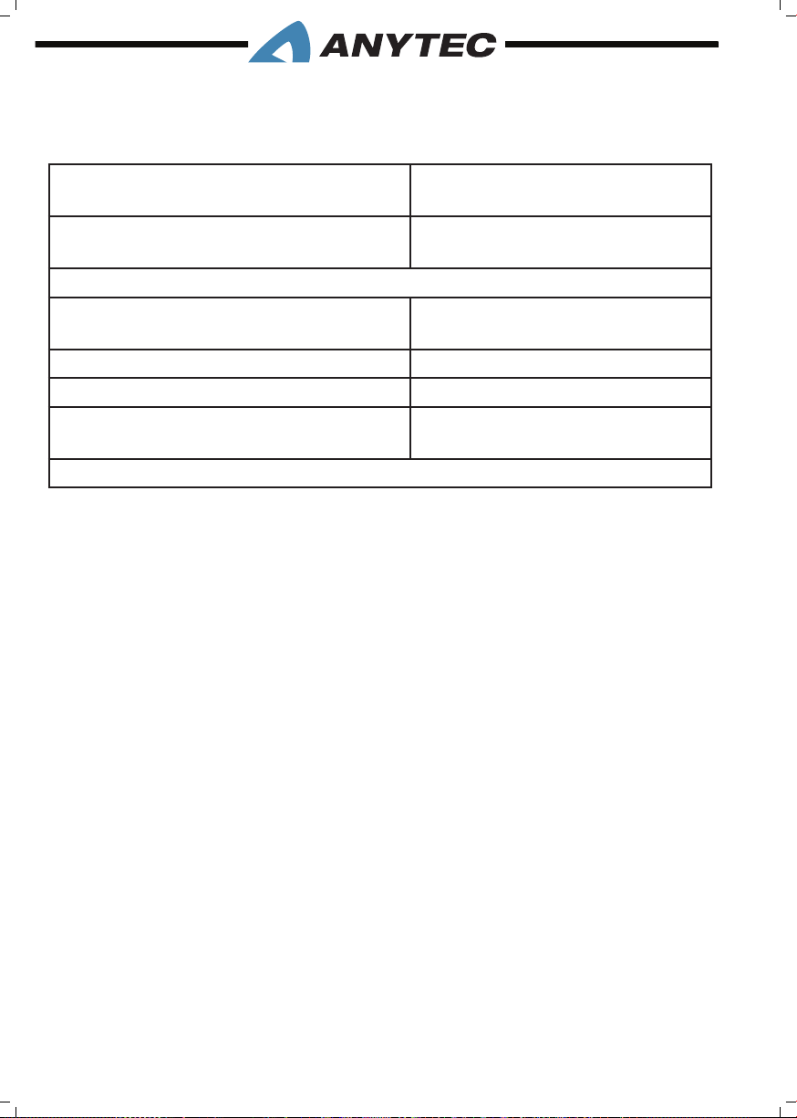
3.4 vEssEL stABiLity AnD BuOyAnCy
The following maximum load has been used for assessing the stability and buoyancy comprising:.
Manufacturer’s maximum recommended
663 kg
load per ISO 14946
Fuel, fresh water, other uids to maxi-
135 kg
mum capacity of xed tanks
This assessment has been made assuming that
The boat in the empty boat condition has
1070 kg
a mass of
Weight of maximum crew 450 kg
Luggage & carry on weights 60 kg
The maximum recommended engine
267 kg
outboard mass is
Note: All standard and extra equipment listed in this manual is aboard
Your boat is manufactured to specic stability and otation standards for the capacity
shown on the certication plate. Maximum recommended load included the weight of all
persons aboard, all provisions and personal effects, cargo (if any) and all consumable liquids
(water, fuel, etc.). Any increase from the recommended load capacities will put your boat
in jeopardy of capsizing, swamping and sinking.
Also, any changes to the masses aboard may signicantly affect the stability, trim, and performance of the boat. Stability can be considerably affected by loose uids or weight within
the vessel. Keep the bilge area as dry as possible, and in rough weather or at planing speeds,
keep all openings, hatches, lockers, doorways, and windows closed to minimize ooding.
Breaking waves are a serious stability hazard. Finally, stability can be compromised when
towing or lifting heavy weights using a davit or boom.
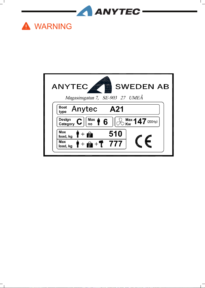
3.5 LOAD CApACity / CE siGn
The load capacity plate, located on the freeboard next to the portside passenger seat,
indicates the maximum weight and number of persons your boat can handle under calm
sea conditions. It also states the maximum engine power and weight. Do not exceed the
capacities stated. A full explanation of this information can be found in the relevant sections
of this manual.
The information present on the certication plate does not relieve the operator of responsibility. Use wise and sound judgement when placing equipment and passengers on
your boat.
3. GENERAL INFORMATION__PAGE 28
Page 37
1. Do not exceed the maximum recommended number of persons. Regardless of the number
of persons on board, the total weight of persons and equipment must never exceed the
maximum recommended load. Always use the seats/seating spaces provided.
2. When loading the craft, never exceed the maximum recommended cargo /luggage load.
Always load the boat carefully and distribute loads appropriately to maintain design trim
(approximately level boat), and secure loose equipment when underway. Avoid placing heavy
weights high up.
3.6 pAssEnGER LOCAtiOns AnD EMBARkinG/DisEMBARkinG
The gure below shows suitable passenger locations and where to step while embarking/
disembarking the boat.
Ask passengers to be seated while the boat is moving, and to hold on to handrails when
seated and while embarking/disembarking. Do not use the bow cockpit when operating
the boat at higher speeds than 10 knots, or in high wave conditions.
The safest and recommended point of embarking/disembarking is the bow. The anti-slip
patterns cover the elevated bow deck and there are handrails to hold on to.
When moored steadily alongside a jetty, passengers may also use the SB and PS stern step
areas next to the targa bow, refer the gure given in page 30.
Be very careful as the surfaces are narrow and may be slippery when surfaces, shoes or
feet are wet or dirty. Be aware of that the boat may move due to the shift of weight and
waves. Make sure the distance to the jetty is short enough and the boat cannot move away
from the jetty. Hold on tight to boat handrails and rm objects on the jetty and ask for
support from fellow passengers.
3. GENERAL INFORMATION__PAGE 29
Page 38
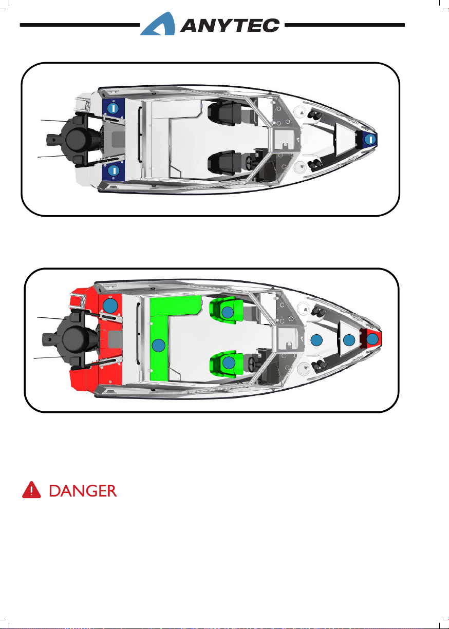
Embarking/disembarking area
1. The safest and recommended area
Passenger positions
1
2
2
3 3
2
1
1. Area to be used during anchoring, mooring and emergency operation
2. Area to be used at speeds above 10 knots
3. Area to be used at speeds up to 10 knots.
Surfaces are slippery when wet or dirty. Use extreme caution when walking on wet surfaces.Never
occupy the working decks while the boat is underway. Hold on to handrails and structures to the
extent possible.
Be aware of your footing while the boat is underway. Slipping or falling can result in serious injury
or death, especially if the boat is in motion or in rough seas. Keep the cockpits clean, so if movement is necessary, it will be free of obstructions.
3. GENERAL INFORMATION__PAGE 30
Page 39
Do not sit in the bow area (in front of cockpit) when the boat is moving at speeds higher than 10
knots, or in conditions with high waves.
3.7 sAfEty LABEL LOCAtiOns
Mounted at key locations throughout your boat, and duplicated in this chapter, are labels
which advise you of imperative safety precautions. Learn to recognize and understand the
labels before operating the boat. These precautions are not all-inclusive.
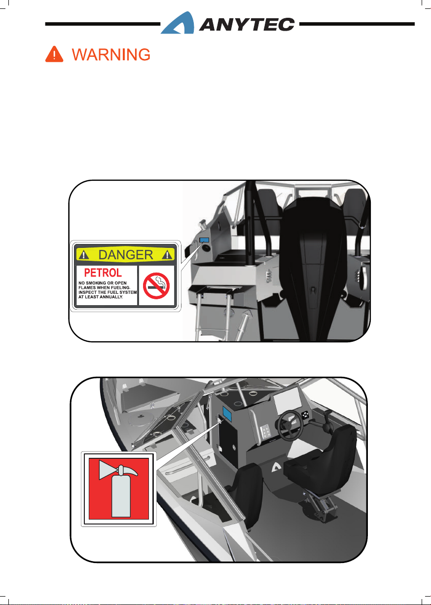
Location: Next to the fuel lling cap
Meaning: No open ames in boat when fueling. Inspect fuel system at least annually.
Location: At the door of the starboard pulpit storage.
Meaning: Shows location of re extinguisher
3. GENERAL INFORMATION__PAGE 31
Page 40
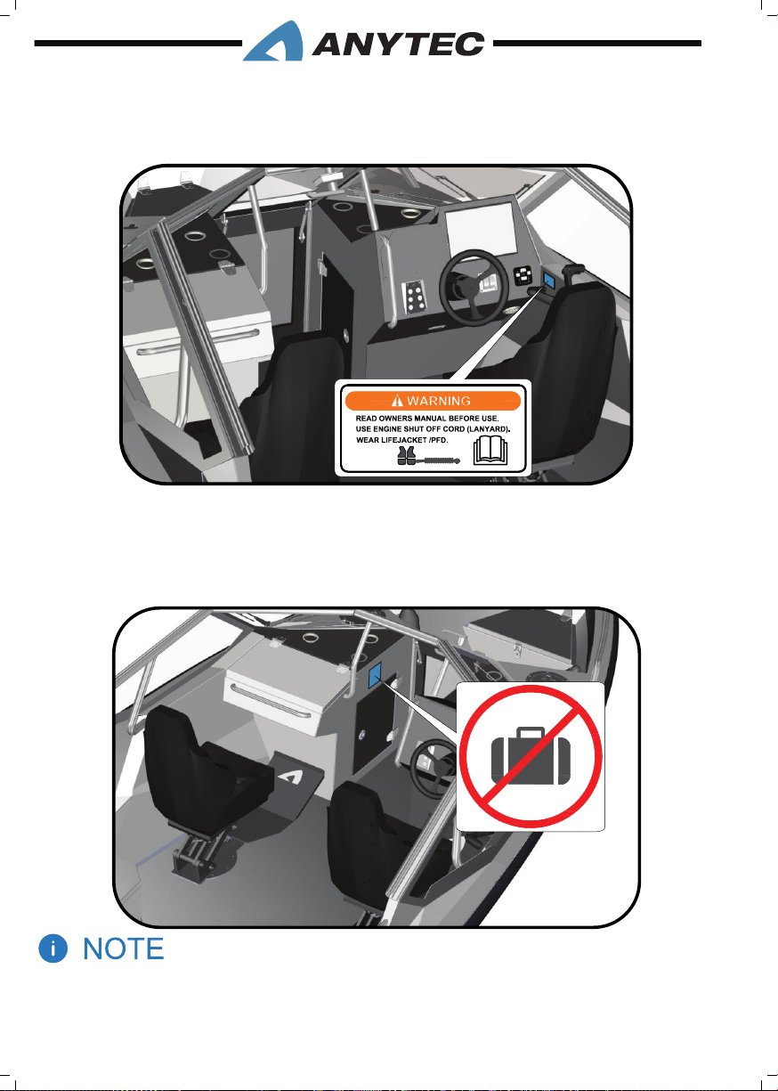
Location: Next to the throttle, at helm area
Meaning: Read this manual before using the boat. Always wear PFD/lifejacket, operator to
use the engine shut-off cord when the boat is underway.
For boats with Webasto heater (optional):
Location: At the hatch where the Webasto fuel tank is stored.
Meaning: Do not store any items/luggage in this compartment as it may block the ventilation of fumes from the Webasto fuel tank.
Do not remove or obstruct any safety label. Replace any label which becomes illegible. Replacement to the safety labels can be obtained by contacting your dealer.
3. GENERAL INFORMATION__PAGE 32
Page 41
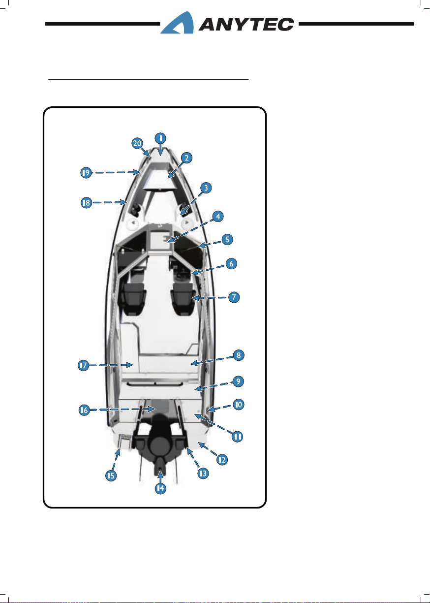
3.8 BOAt LAyOut
3.8.1 Boat layout. Standard equipment
1. Bow platform
2. Bow sofa & storage
3. Bow storage (PS&SB)
4. Front door
5. Wipers (PS&SB)
6. Steering wheel
7. Anytec stand & seat (PS&SB)
8. Main electric panel inside sofa
9. Canopy garage
10. Stern cleats
11. Stern storage (PS&SB)
12. Swimming platform (PS&SB)
13. Targa tower
14. Top light
15. MOB rescue & swim ladder
16. Motor well access plate
17. Cockpit sofa & storage
18. Bow rail (PS&SB)
19. Bow cleats (PS&SB)
20. Secure eye
3. GENERAL INFORMATION__PAGE 33
Page 42
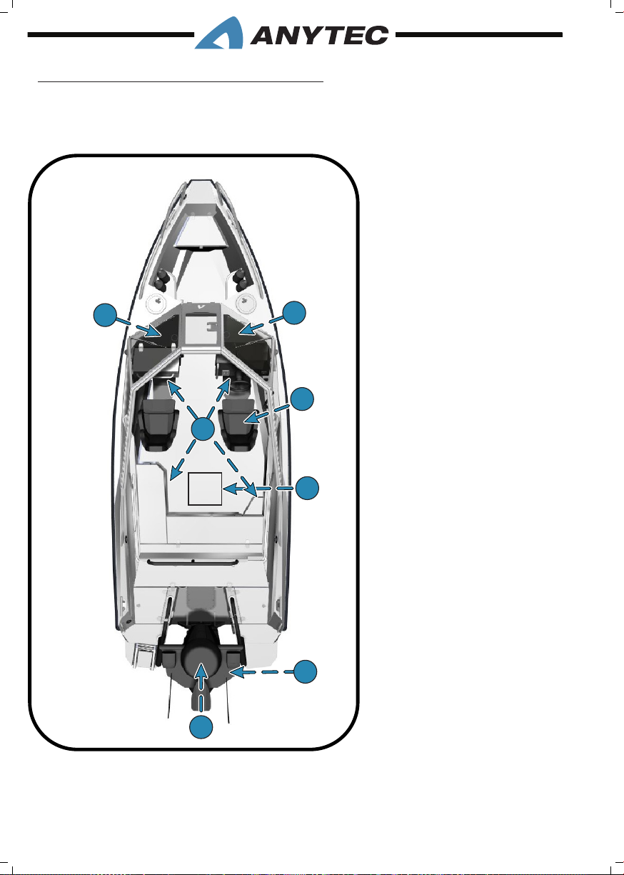
3.8.2 Boat layout, optional equipment
1
1
1
2
3
5
4
6
Conguration 1::
1. Webasto heater (SB) and
fuel tank (PS), installed in
the storages under the
helms
2. Anytec performance suspension seat stands
3. Table
4. On targa top: Search lights,
IR cameras, VHF antenna
5. 3G or 4G radar system
antenna (radar module is
under helm)
6. Audio system (remote on
3. GENERAL INFORMATION__PAGE 34
helm, audio box below
helm) with loudspeakers in
cockpit
Page 43
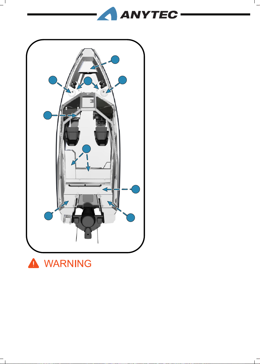
3.9 stORAGE AREAs
1
1
1
3
4
6
2
5
3
6
7
1. Bow sofa storage
2. Fender holders (PS & SB)
3. Bow watertight storages (PS &
SB)
4. Cockpit sofa storage
5. Canopy garage
6. Stern storage (PS&SB)
7. Glove compartment (navigator
storage)
1. Do not store any equipment containing petrol (outboard engines, portable petrol tanks, etc.)
in the stern cockpit sofa. The stern cockpit sofa was not designed to store petrol since it
contains electrical equipment which may cause sparks.
2. Do not store any equipment in PS pulpit storage if you have the optional Webasto fuel tank
installed there. You block the air ventilation or damage the fuel line.
3. Do not ll ventilated storage compartments with goods/equipment to the extent that hin-
ders the. Ventilation is needed to remove gas and fumes that may occur in these areas. Be
particularly careful with the storages below the stern cockpit sofa as it contains batteries
and electric breakers/fuses.
3. GENERAL INFORMATION__PAGE 35
Page 44
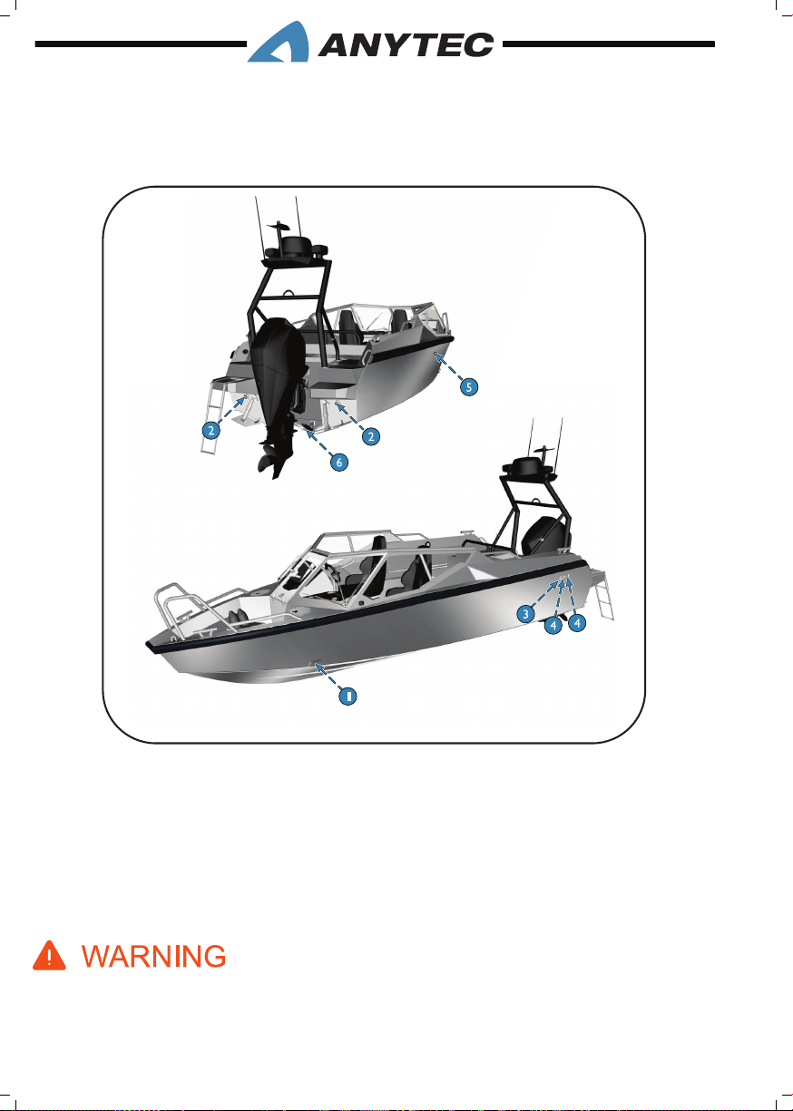
3.10 thRu huLL LOCAtiOns
The gure given below shows the locations of thru hull locations. All openings except
bottom plug are located above water level even if the boat is fully loaded (max load acc. to
this manual, mooring in at water conditions).
1. Bow cockpit drain
2. Stern cockpit drain
3. Fuel ventilation / overll
4. Bilge pump outlets ( manual and electric)
5. Webasto heater exhaust (optional)
6. Bottom plug
This boat has an underwater tting on the transom plate with a drain bottom plug (see gure).
This plug must be in place and tightened before the boat goes into the water. The boat will sink
without this plug in place.
3. GENERAL INFORMATION__PAGE 36
Page 45
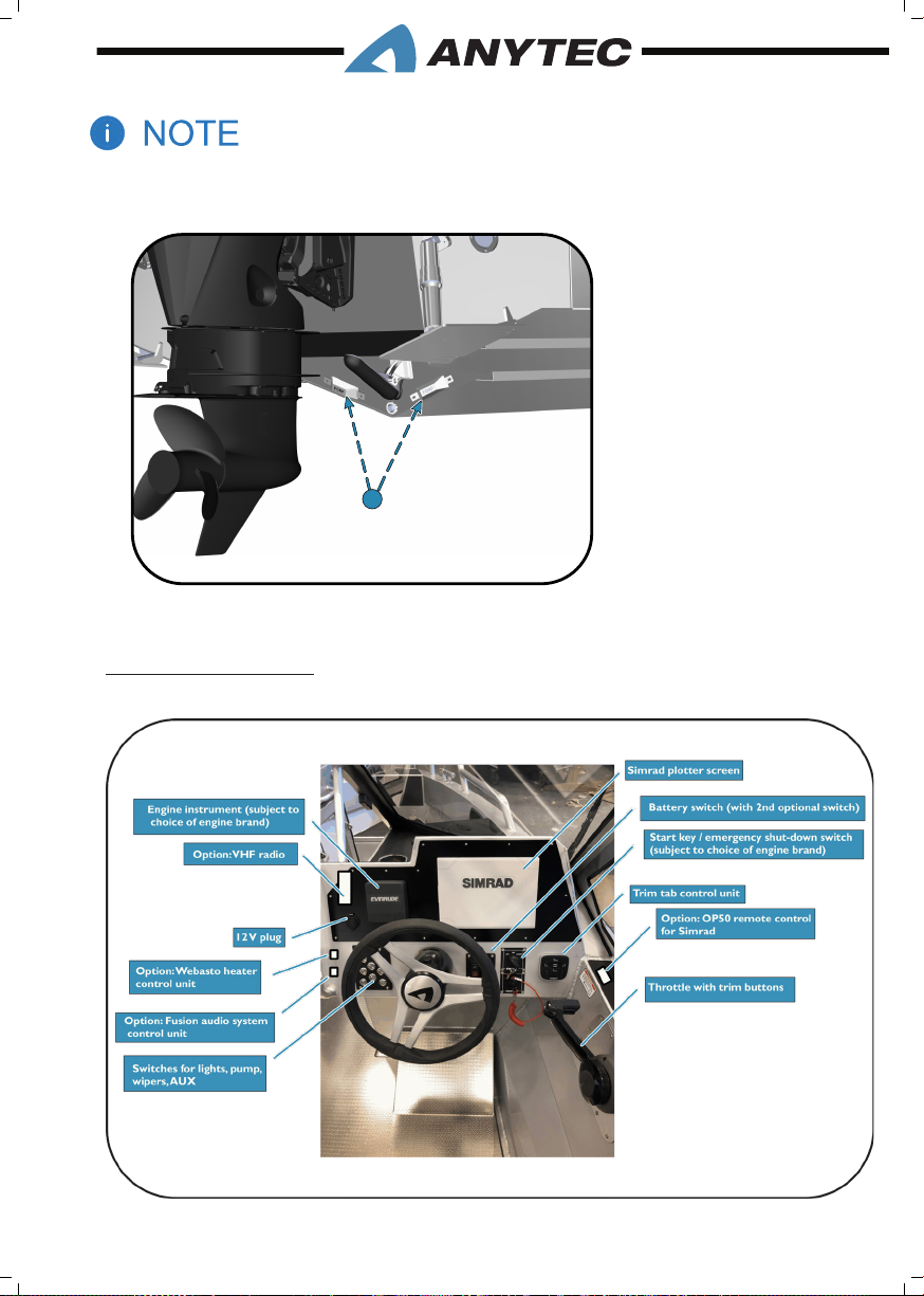
The deck drains provide self-bailing capabilities while the boat is static in the water. This prevents
1
accumulation of water in the cockpit, for instance generated by rain.
1. Bottom plug
3.11 DAsh LAyOut (stAnDARD AnD OptiOnAL EquipMEnt)
3.11.1 Dash layout
3. GENERAL INFORMATION__PAGE 37
Page 46

3.11.2 Dash switch panel
1
2
2. Navigation lights
1. Bilge pump
4
3. Wipers low speed
4. Anchor light
3
7
5
5. Wipers high speed
6. Auxilliary button 1
7. Auxilliary button 2
6
AUX 1
AUX 2
8
AUX 3
8. Auxilliary button 3
3.12 tRAiLERinG
Anytec do not offer a specic trailer for this boat. Your Anytec dealer can recommend or
sell you a suitable trailer. Before placing your Anytec boat onto any trailer, make sure that
the trailer is designed for your boat weight and its shape.
• The trailer should have a bow rest, center keel rollers and keel guards/wobble rollers
which will distribute the weight properly, offering good support for the keel and
hull in both vertical and horizontal direction. Adjust the side supports so that the
maximum boat weight rests on the keel supports and the supports on sides offer
only lateral support.
• The mass of your boat in trailering condition is found in chapter 3.1. This includes
the weight of the maximum size engine and a fully optioned boat along with full liquid
loads. This does not include luggage/gear weight, any crew or any water inside the
boat. Always remove any unnecessary weight such as loose accessories and luggage
from the boat and drain the bilge water before trailering.
• Refer to the engine manual for any specic instructions on trailering, such as the best
engine position and securing method.
• Make sure you secure all loose items in the boat. Do not use the canopy, boat
covers or other similar top or cover on the boat during trailering. These can become
detached at high speeds and damage the boat and cause a danger to trafc.
3. GENERAL INFORMATION__PAGE 38
Page 47
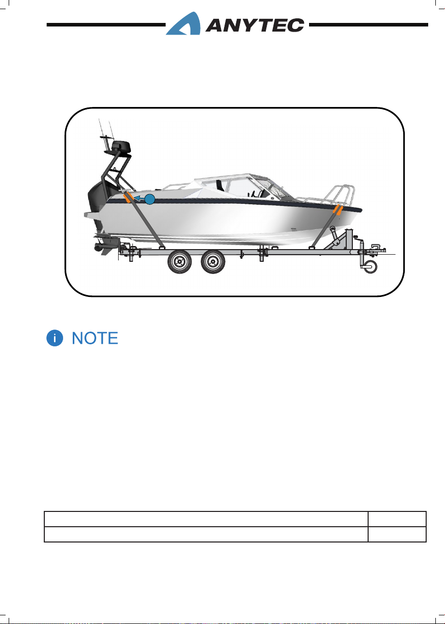
• Always secure the boat to the trailer using suitable straps attached to boat cleats and
1
1
trailer strong points. Be careful not to damage the boat fenders. Apply cloths between
fenders and straps and do not tighten straps so hard that fenders are deformed. If
possible, try to fasten the straps in an angle as shown in the gure below..
1. Cloths between fender & straps
Tightening straps too hard across the boat fender may damage the fender. Be careful and use rags
or other material between fender and straps/ropes.
Principal gure only
3.13 stROnG pOints
Cleats
Your boat comes equipped with 4 cleats, two located at the bow, and two located at the
stern. The cleats are used for mooring, anchoring and towing.
The locations of the strong points that can be used for anchoring, mooring and towing is
shown in the gure given below. Note that amid ship cleats are only intended for mooring
The break strength and intended use of the strong points are as follows:
Bow cleats (PS & SB), anchoring/mooring/towing: 23.6 kN
Stern cleats (PS & SB), anchoring/mooring/towing: 15 kN
3. GENERAL INFORMATION__PAGE 39
Page 48
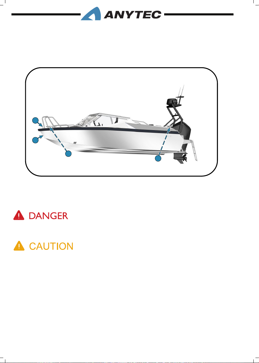
Bow Eye
1
2
1
4
3
Your boat includes a bow eye, which is used to haul and hold your boat onto a trailer, and
a securing eye for locking the boat with a chain. These eyes are not designed for lifting,
mooring, anchoring or towing of the boat.
1. Bow eye (trailer/winch eye)
2. Bow cleats (PS&SB)
Use only the lifting procedure specied in this manual. It is dangerous to use cleats, secure eye or
bow eye for lifting and can cause serious injury or death
Breaking strength of ropes and chains must not exceed 80 % of the breaking strength of the strong
point in question.
3. stern cleats (PS&SB))
4. securing eye (lock eye)
3.14 LiftinG Of thE BOAt
Commission only a reputable lifting company or boatyard with sufcient lifting capacity
to lift the boat. In addition to the boat’s weight, also take into account the equipment, and
other possible loads in the boat. Always empty any bilge water before lifting.
The gure given below shows the position of the lift straps. When lifting the boat with lift
straps, Anytec recommends using a forklift or lifting frame to separate the straps from the
upper hull and fender. The straps need to be vertical. If these recommendations are not followed, there may be damages on both hull and fender; any warranty does not cover these.
3. GENERAL INFORMATION__PAGE 40
Page 49
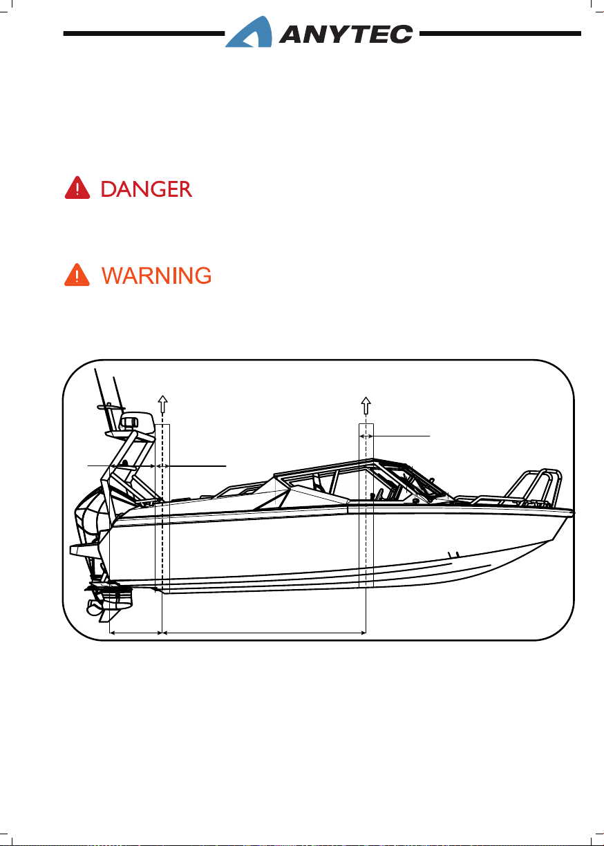
During the lift, make sure that the boat is well balanced and be careful with rails and other
equipment. Ensure that lifting straps do not slide in any direction either on the boat or
the lifting device.
Cover hoist/lift devices with soft material to prevent scratches. Do not stand under the
boat while lifted.
Never stand under the lifted boat. Use only the lifting procedure specied in this manual. It is dangerous to use the cleats, secure eye, bow eye, handrails or other parts of the boat for lifting and
can cause serious injury or death.
Lifting heavy items is always risky and requires specic skills. If you lack that, or in any way feel
uncertain, always contact a professional lifting company or other experienced person.
300
670
300
Lifting area
Lifting area
820
2500
3. GENERAL INFORMATION__PAGE 41
Page 50
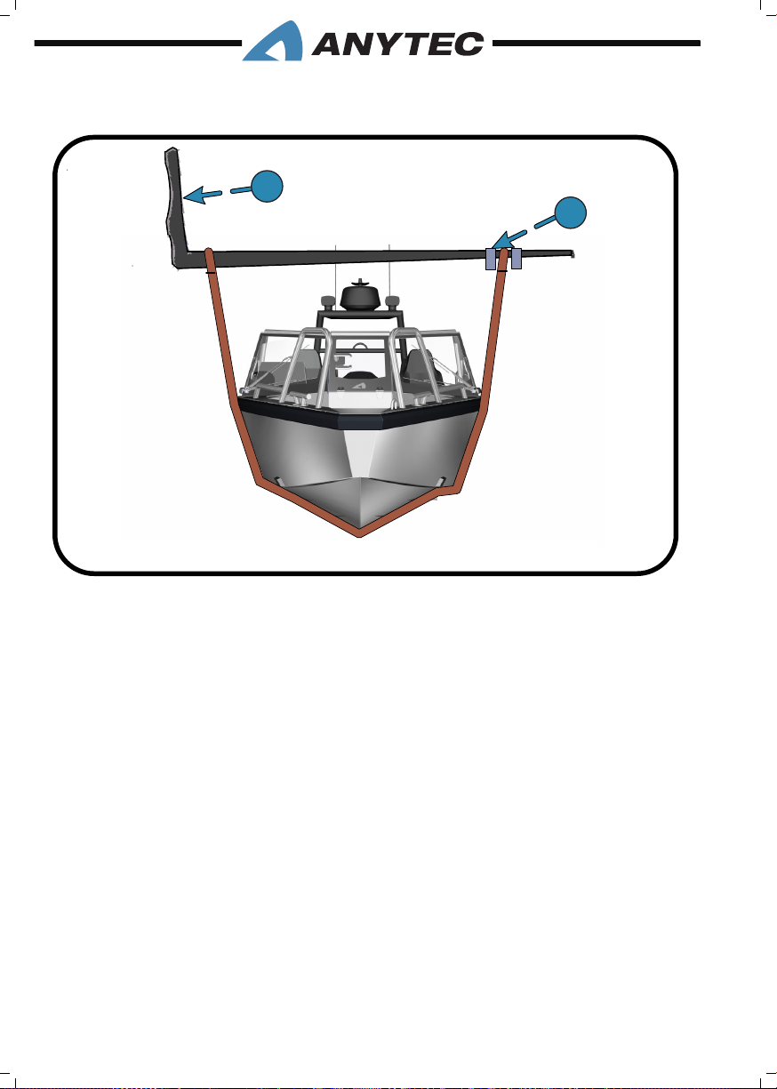
1. Loader fork
2. Anti-slip lock
1
2
3. GENERAL INFORMATION__PAGE 42
Page 51
4. SYSTEMS & COMPONENTS
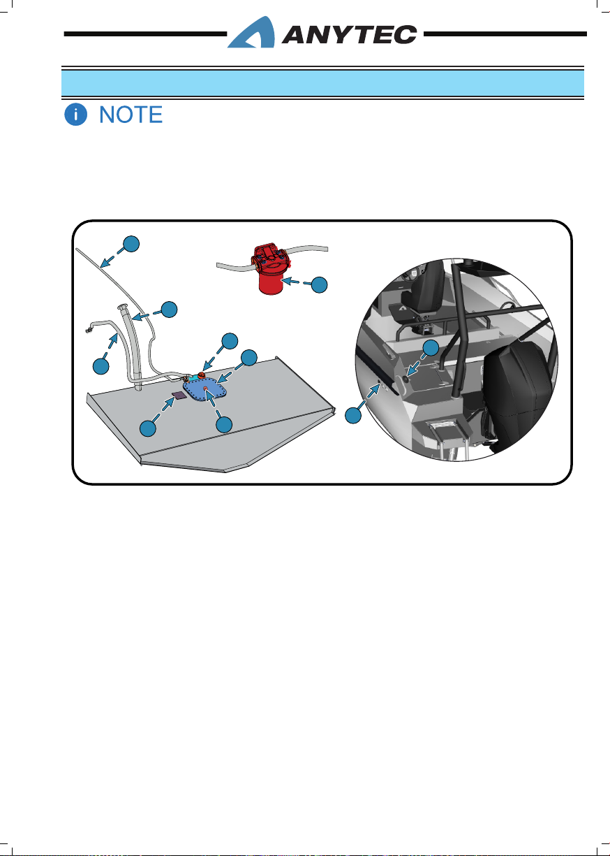
This chapter is based on Anytec-listed standard and optional equipment. Any other equipment or
systems added (custom-made boats, aftermarket products and so on) are not covered here.
Furthermore, outboard engine and engine control instrument details are not included. The engine
can be of multiple brands and models, in the choice of the dealer and customer. Please check the
manuals provided with that engine or consult the dealer who installed it.
7
9
6
2
3
8
1
10
1. Fuel tank inspection hatch
2. Fuel level
3. Fuel vent hoses
4. Fuel vent
5. Fuel ll lid
4
6. Fuel ll hose
7. Fuel line
8. Fuel tank pressure test plate
9. Fuel lter
10. Fuel remove plug for long term
5
storage
4.1 fuEL systEM
Your boat’s fuel system consists of a fuel tank, a fuel tank ll and vent tting, an anti-siphon
valve, a sending unit, and an engine fuel supply line. Besides, there are two extra fuel ports
for optional pickups, if needed.
The factory-mounted boat fuel system (excluding engine) is designed to handle regular
gasoline as well as ethanol-blended gasoline with ethanol content not greater than 15 %
(like E85). However, the engine may not be designed for ethanol-blended gasoline. Before
introducing petrol with ethanol into your fuel tank, ask your dealer if there is an engine or
any components have been added or replaced that may not be ethanol compatible.
4. SYSTEMS & COMPONENTS__PAGE 43
Page 52

4.1.1 Fuel tank
The A27 boat is equipped with an aluminium fuel tank with a capacity of 390 litres. As a
precaution, all capacity may not be useable due to trim and loading conditions, so consider
keeping at a minimum 20% of reserve fuel in the tank.
Fuel tanks with levels less than 20% capacity can cause engine stalling problems due to fuel
starvation or by allowing sediment and dirt to enter the fuel supply lines. Keep the tank full
and monitor the fuel level often to prevent this from happening
4.1.2 Filling the tank
Ensure that the right type of fuel is selected (check engine manual). When lling the tank, do
not attempt to top off the tank. When the nozzle shuts off, the tank is full, and continuing
to ll past the fuel ll shut-off will cause the system to spit back some fuel.
Before fuelling, carefully read the chapter on Fire Prevention in this manual!
4.1.3 Phase separation
Humidity and condensation in your fuel tank can adversely affect the function, in particular
with ethanol blended fuel. A condition called phase separation can occur if water is drawn
into the fuel beyond the saturation point. The presence for water in the fuel beyond the
saturation level separates most of the ethanol in the fuel from the bulk fuel and drops to
the bottom of the tank, signicantly reducing the level of ethanol in the fuel mixture in
the upper level (phase). If the lower level (phase), consisting of water and ethanol, is deep
enough to reach the fuel inlet, it could be pumped directly into the engine(s) and cause sig-
nicant problems. Engine problems can also result from the reduced ethanol/fuel mixture
left in the upper phase of the tank, or just from the water contamination.
If phase separation occurs, your only remedy is to drain the fuel, clean and dry the tank
completely and rell with a fresh, clean tank of fuel.
To avoid these problems avoid water accumulation in the tank. Try to maintain a high fuel
level in the tank, in particular when the boat is not in use for longer periods. This reduces
the air ow in and out of the tank due to changes in temperature as well as limiting fuel
exposure to humidity and condensation.
4.1.4 Fuel lter
As a part of the fuel system, a fuel lter is installed in-between the tank and the engine.
There is always an external lter mounted in the boat. The exact location varies between
engine brands and engine installation companies. Some engines also have a lter under the
engine hood.
Maintenance of the fuel lter is essential to secure a reliable operation. For some engines,
the lter can also be connected to the instrumentation and provide a warning if it need
maintenance.
Please check the instructions provided by the dealer who installed the engine.
4. SYSTEMS & COMPONENTS__PAGE 44
Page 53
Petrol vapours can explode. Never smoke while handling or lling up the petrol tank. Leaking fuel
is a re and explosion hazard. Inspect the fuel system annually to make sure that there are no leaks
and corrosion in the system.
1. Do not obstruct or modify the fuel ventilation system, as that could cause res or explosions.
2. Do not store any equipment containing petrol (outboard engines, portable petrol tanks, etc.)
in any cockpit storage areas. These compartments were not designed to store petrol and do
not have adequate ventilation.
Gasoline fuels with ethanol content, like E85, could seriously damage your engine and void warranty. Always check the engine owner’s manual for fuel recommendations and any approved additives
before the rst use.
For complete instructions on operation and maintenance, we refer to the separate
OEM owner’s manual that was developed specically for this equipment. It is provided with the Anytec document bag.
4.2 stEERinG systEM
As standard, this boat comes equipped with a hydraulic steering system consisting of a
steering wheel, a hydraulic helm pump, hydraulic hoses and a hydraulic steering cylinder. An
optional steering wheel with tilt function (to adjust wheel angle) is also installed on certain
boats. However, depending on the engine brand and model, the steering system may have
been upgraded to either:
• A hydraulic steering system as above, but with power servo for easier turning. The
servo is then located in the stern electrical compartment.
• A system with electronic steering control combined with hydraulic servo and
cylinder. The steering wheel controls the power servo by wires instead of hydraulic
hoses. The power servo is installed at the stern electrical compartment.
For complete instructions on operation and maintenance, refer to separate OEM
owner’s manual that was developed specically for this equipment. It is provided by
the party who installed the engine.
Failure of the steering system will cause loss of control of your boat. Any change in steering such
as looseness, tightness, binding, etc., must be checked immediately by a qualied person
All components of the steering system must undergo periodic inspection & maintenance to ensure
safe operating conditions. Refer to the maintenance section of this manual for further details.
4. SYSTEMS & COMPONENTS__PAGE 45
Page 54
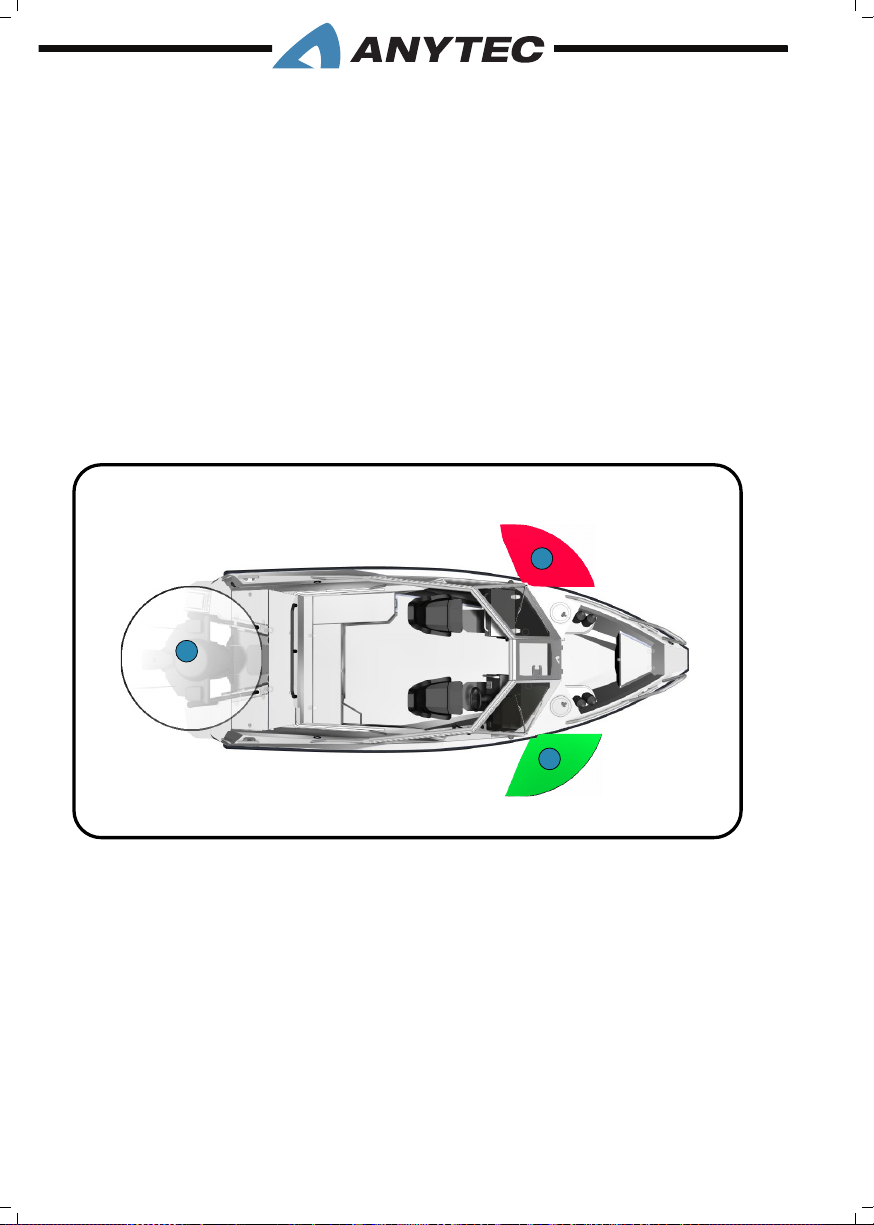
4.3 nAviGAtiOn LiGhts
Your boat comes equipped with navigation lights for use at night or in low visibility conditions. The use of navigation lights at low visibility conditions is mandatory in most countries and waters; it is always important for your own, as well as other’s safety at sea. Local
regulations may vary.
The navigation light switches are located at the dash switch panel.
To turn on the Navigation Lights, press “Navigation lights” button (refer chapter 3.11.3).
This illuminates the port (red), starboard (green) and all-around light (white) showing other vessels that you are underway.
There is a separate button to active the Anchor light. If activated, only the white all-round
light turns on. To turn off the Navigation Lights, press “Navigation lights” or “Anchor light”
buttons again.
Prior to running at night, make sure that all navigation lights are working well.
1
3
2
Principal gure only
1. 112.5° Port navigation light (red), visible 2NM
2. 112.5° Port navigation light (green), visible 2NM
3. 360° All around light (white), visible 2NM
4.4 BiLGE puMps
Your vessel is equipped with two bilge pumps, one electrical and one manual.
The electrical pump is located in the bilge near the transom, and the manual pump is located on the outside of the stern cockpit, close to the engine well.
Access to the aft electrical bilge pump is via the motor well access plate, while the stern
platforms can access the manual bilge pump.
4. SYSTEMS & COMPONENTS__PAGE 46
Page 55
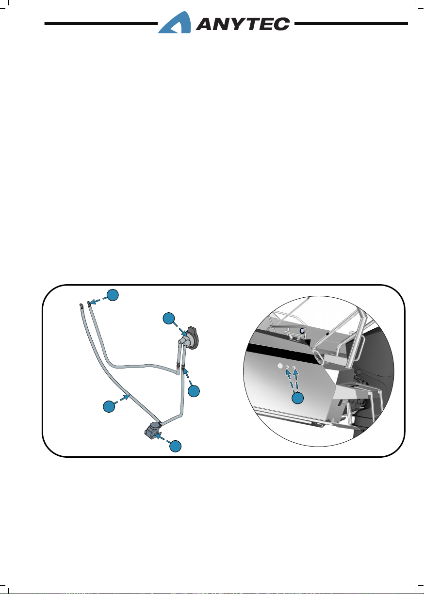
The electrical bilge pump is rated for 2271 litres/hour and is activated automatically by a
free-oat switch when water in the bilge reaches a predetermined level. In normal conditions, there shall not be any water in the bilge. If there is water, it is due to the leaks from
above (deck, tting, inspection covers) or damage to the hull (seawater leaks). The reason
for the leakage is to be determined and corrected soonest possible!
The bilge pumps can provide you with crucial extra time if your boat is taking in water,
allowing you to nd and deal with the source of a leak or, in extremes, to put on life jackets
and hopefully keep your boat aoat long enough for help to arrive. However, please note
that the pump capacity cannot keep up with major leaks.
You can also manually activate the electric bilge pump at the console switch panel by
pressing and holding the bilge pump button (refer chapter 3.11.3 for dash layout). Push this
button and hold it to operate the bilge pump.
The manual bilge pump is only intended as a back-up pump in case of electrical failures
hindering the use of the electric pump. It is rated at 34.5 litres/minutes @ 45 strokes per
minute.
For complete instructions on operation and maintenance, we refer to the separate
OEM owner’s manual that was developed specically for this equipment. It is provided with the Anytec document bag.
3
2
5
1. Electrical bilge pump
2. Manual bilge pump
3. Bilge pump outlets
4. Thru bulkhead connection
5. Bilge hoses
4. SYSTEMS & COMPONENTS__PAGE 47
4
1
3
Principal gure only
Page 56
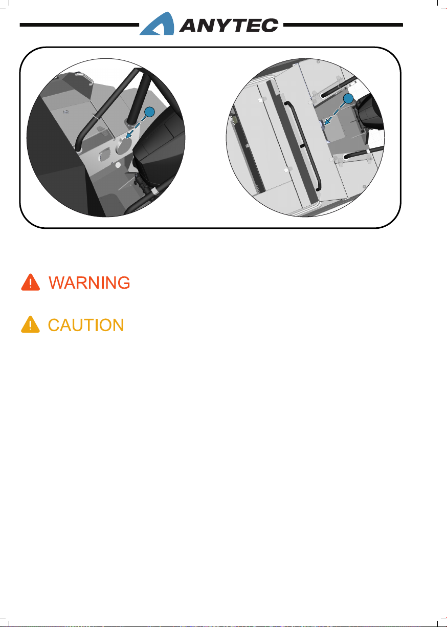
2
1
1. Manual bilge pump location
2. Electrical bilge pump location (below access hatch)
The bilge pumping system is not designed for damage control.
Check the function of all bilge pumps at regular intervals. Check the function of the electric bilge
pump by emptying the bilge manually with the spring-loaded switch located on the switch panel
every time before using the boat. Check for debris at and around the pump inlet (open inspection
hatch to check). Bilge pump failure could potentially cause the boat to sink if there is an unnoticed
water leakage.
4.5 siMRAD ® MuLtifunCtiOn DispLAy & nAviGAtiOn systEM
The boat as standard is delivered with a multifunction display model NSS12 Evo3 by Simrad and includes many functionalities such as depth sonar and navigation charts. The Simrad
panel can connect and display further data from the engine, stereo system, fuel tank and
other external equipment (depending on options installed). The cockpit helm installs this
panel.
This is a list of main data and functions that can be provided by this unit:
• Navigation charts and tools
• Depth sonar
• Water temperature
• Fuel level, main tank
4. SYSTEMS & COMPONENTS__PAGE 48
Page 57
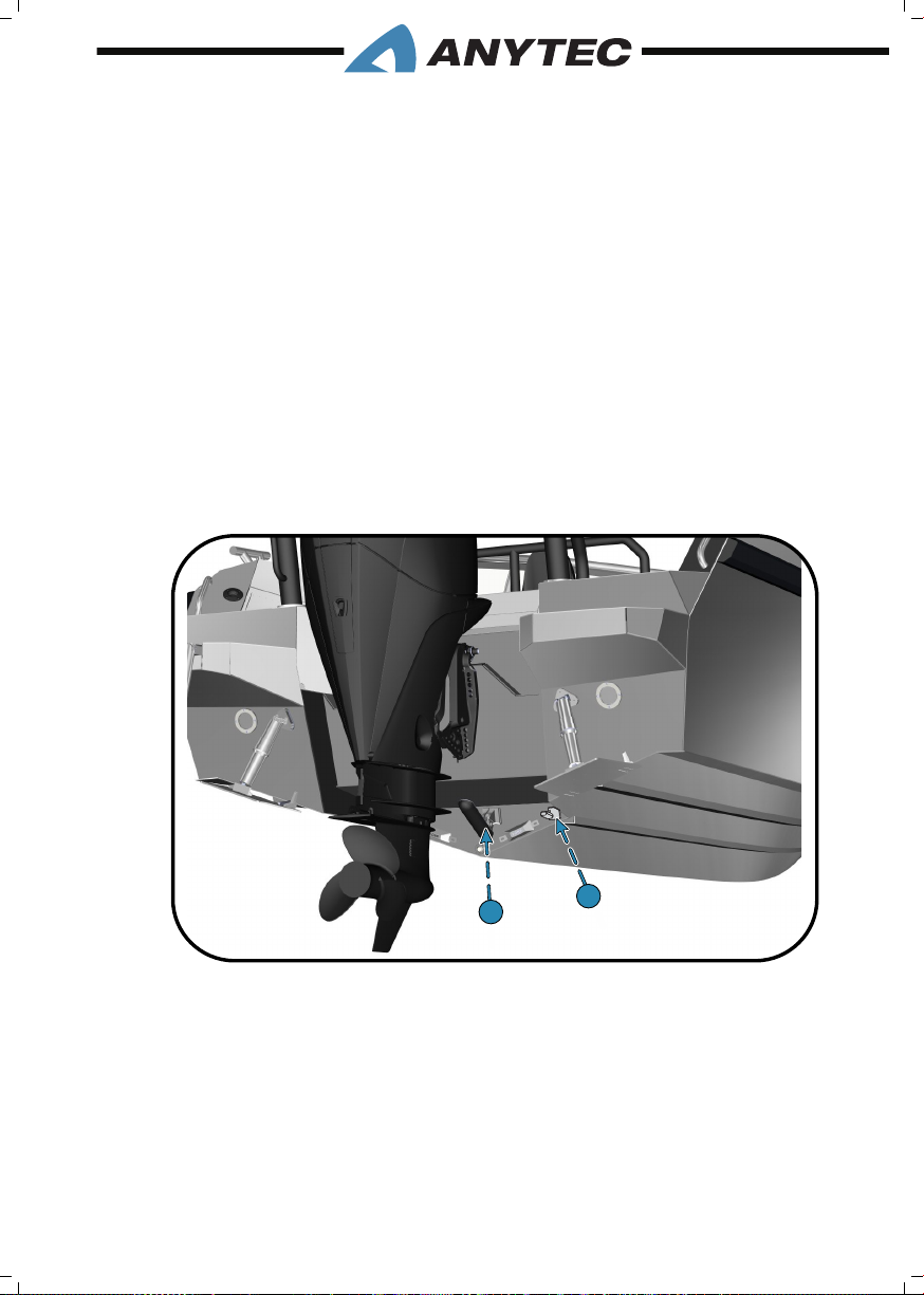
• Simrad wireless network
1
2
• Display engine data
Your boat may be equipped with one or several Simrad options like:
• Structure Scan 3D view
• Autopilot module
• 3G or 4G Radar module
• NAIS 500/ NSPL 500 AIS module with combo antenna
• Upgraded Simrad unit (NSS12, NSS) or Go12)
• OP 50 remote control for Simrad unit
The depth and water temperature transducer/sensor, as well as Structure Scan transducer,
are mounted on the transom in bottom recess (refer the gure given below). Be careful
not to damage it when the boat is lifted or winched to a trailer or cradle, or at very shallow waters
1. Structure scan
2. Standard transducer/sensor
Due to the advanced technology of the Multifunction display, we refer to the OEM manual. Your Anytec dealer can also assist you if needed, as a great deal, customization of the
functions is possible.
For complete instructions on operation and maintenance, we refer to the separate
OEM owner’s manual that was developed specically for this equipment. It is provided with the Anytec document bag.
4. SYSTEMS & COMPONENTS__PAGE 49
Page 58

4.6 EnGinE COntROLs AnD instRuMEntAtiOn
The engine controls and the instrumentation will vary depending on the engine brand
and model; thus it is covered by the engine owner’s manual. Refer chapter 3.11 for typical
locations of controls and instruments.
Gas and gear throttle
This control is used for controlling the gear and has 3 positions (forward, neutral, backward). To shift it in neutral while engine is running, the engine rpm must be at idle. In neutral, there is a lock button to allow the rpm to increased, for instance for engine warm-up
or tests. Refer engine manual.
Power trim and tilt
At one side of the tip of the throttle handle, there are 2 buttons. One raises the engine, and
the other lowers the engine. This function is a combined trim & tilt functions.
The power tilt (power lift) allows you to raise and lower the engine for trailering and
launching the boat and keeps the engine out of the water while moored at the port. The
power tilt is activated automatically when the engine rises outside the trim (operation)
angles.
The same control is also used for the power trim. At the lower range of the engine movement angles, the power trim allows you to adjust the engine to create the optimum boat
trim (raise/lower the bow), refer chapter 2.6.
Engine Instrumentation
All modern engines are equipped many sensors, allowing useful information and alarms
to be displayed at instruments placed at the helm. Examples are engine temperature, rpm,
trim angles, fuel lter problems, oil levels and general alarms.
Depending on the engine brand, model and options, the information can either be displayed on a separate engine control display mounted to the helm, or be displayed on the
Simrad NSS12 Evo3 Multifunction display. In the latter case, the NSS display can hold all
vital data about boat, engine and navigation matters. The display area can be arranged in
numerous ways to t your personal preferences.
In some cases, customers choose to have a dedicated engine display and the NSS display
mounted at the helm. In addition, most engines have a summer alarm, giving you a warning
noise in case of serious problems.
Due to many variations and possibilities to install and customise the displays, you need
to study the engine and engine instrumentation manuals. They are to be provided by the
Anytec dealer or other company who installed engine and instruments. Understanding the
instruments ensures that you use the engine in the most optimal, economical and safe way.
4. SYSTEMS & COMPONENTS__PAGE 50
Page 59
For complete instructions on operation and maintenance, we refer to the separate
OEM owner’s manual that was developed specically for this equipment. It is provided with the Anytec document bag.
4.7 LECtROtAB tRiM systEM
The boat is as standard equipped with a trim tab system from Lectrotab. The system consists of 2 Trim Tabs and a control unit for these. Trim tabs can help you control and adjust
the boat’s scrolling (transverse slope). The control panel is located at the instrument helm,
see chapter 3.11. refer chapter 2.6 to learn how to use them.
The trim tabs are mounted at the bottom of the transom. They are made of aluminium.
Electromechanical pistons adjust them up/down, so there is no hydraulic oil in these.
Please read about how to trim the boat under section 2.6. Being able to manage trim correctly is
of outmost importance to safety, comfort and fuel economy.
For complete instructions on operation and maintenance, we refer to the separate
OEM owner’s manual that was developed specically for this equipment. It is provided with the Anytec document bag.
4.8 sWiM LADDER/MOB REsCuE LADDER
The boat is equipped with a swim ladder which also serves as a MOB rescue ladder, refer
chapter 2.3.
It is located at the SB swim platform. The ladder is secured with a spring clip and can be
pulled down from water without any need to release it. Always make sure the ladder is
securely landed in the spring clip after use so that it does not fall into the water in case of
heavy boat movements. It is important to check the function every season, refer maintenance chapter 6.3.8.
1. A faulty or blocked ladder may jeopardise man-over-board rescue. It may be very hard or impossible to enter the boat from water without the ladder, which in turn may cause drowning.
2. A rotating propeller can be lethal for a swimmer or person who has fallen overboard, or a
person using the ladder to board the boat or to enter the water. Shut down the engine and
activate the emergency switch (dead man’s switch) if there is any person in the water behind
the engine, and always before using the ladder.
4. SYSTEMS & COMPONENTS__PAGE 51
Page 60
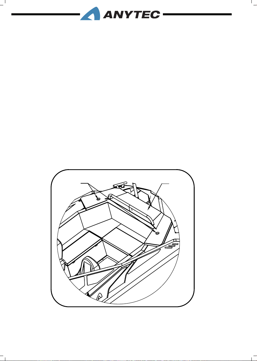
4.9 WinDshiELD WipERs
Your boat is equipped with a two-speed windshield wiper system on the starboard and
port side windshields for use in inclement weather.
To use wipers in low speed press “Wiper low speed” button on the dash switch panel
(refer chapter 3.11.3). For using wipers in high speed switch off wipers from low-speed
mode if they are ON and then press “Wiper high speed” button.
To switch off the wipers press “Wipers low/high speed” button one more time.
4.10 CAnOpy
A canopy with frames and vinyl panels is supplied as standard equipment. When not in use,
the canopy is stored in the canopy garage where it does not interfere with the use of the
boat (see the gure).
If the canopy is used with the side panels mounted ( thus as a full enclosure), always ensure
that there is sufcient ventilation by keeping the air inlets (mounted on the cockpit side
panels) open and by having canopy sections open to allow airow through the cockpit. Also
refer chapter 2.7 about Carbon Monoxide positioning risks.
1
1. Canopy garage locks
2. Canopy garage
4. SYSTEMS & COMPONENTS__PAGE 52
2
Page 61
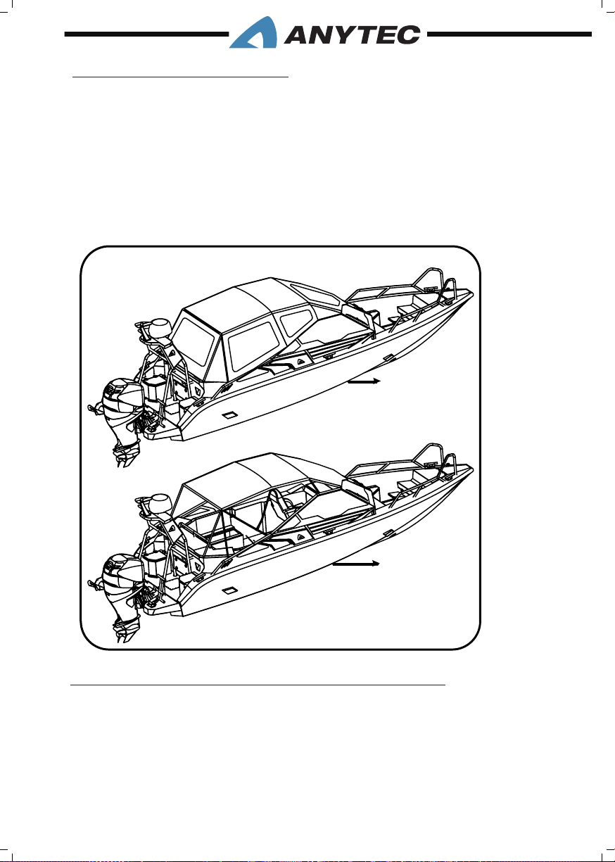
4.10.1 Canopy congurations
Sunroof mode
By using only the canopy top and front vinyl panel, the canopy can be used as sunroof
(see the gure). Loose panels are best stored by rolling them, as this is most gentle to the
windows.
Fully enclosed mode
The side and rear vinyl panels can be installed to enclose the complete stern cockpit. Each
panel attaches to the top part with zippers (see the gure).
1
2
1. Fully deployed
2. Sunroof
4.10.2 How to install, remove and store the canopy
A separate step-by-step Canopy Guide is provided with the boat, check the Anytec bag.
It can also be downloaded from Anytec website. Please study the guide to learn how to
operate the canopy in a fast way, and ensuring best possible lifetime.
Aviod to fold and store a wet or very dirty canopy, as it may cause severe mildew problems.
Let is dry rst. For maintenance of the canopy, see chapter 6
4. SYSTEMS & COMPONENTS__PAGE 53
Page 62
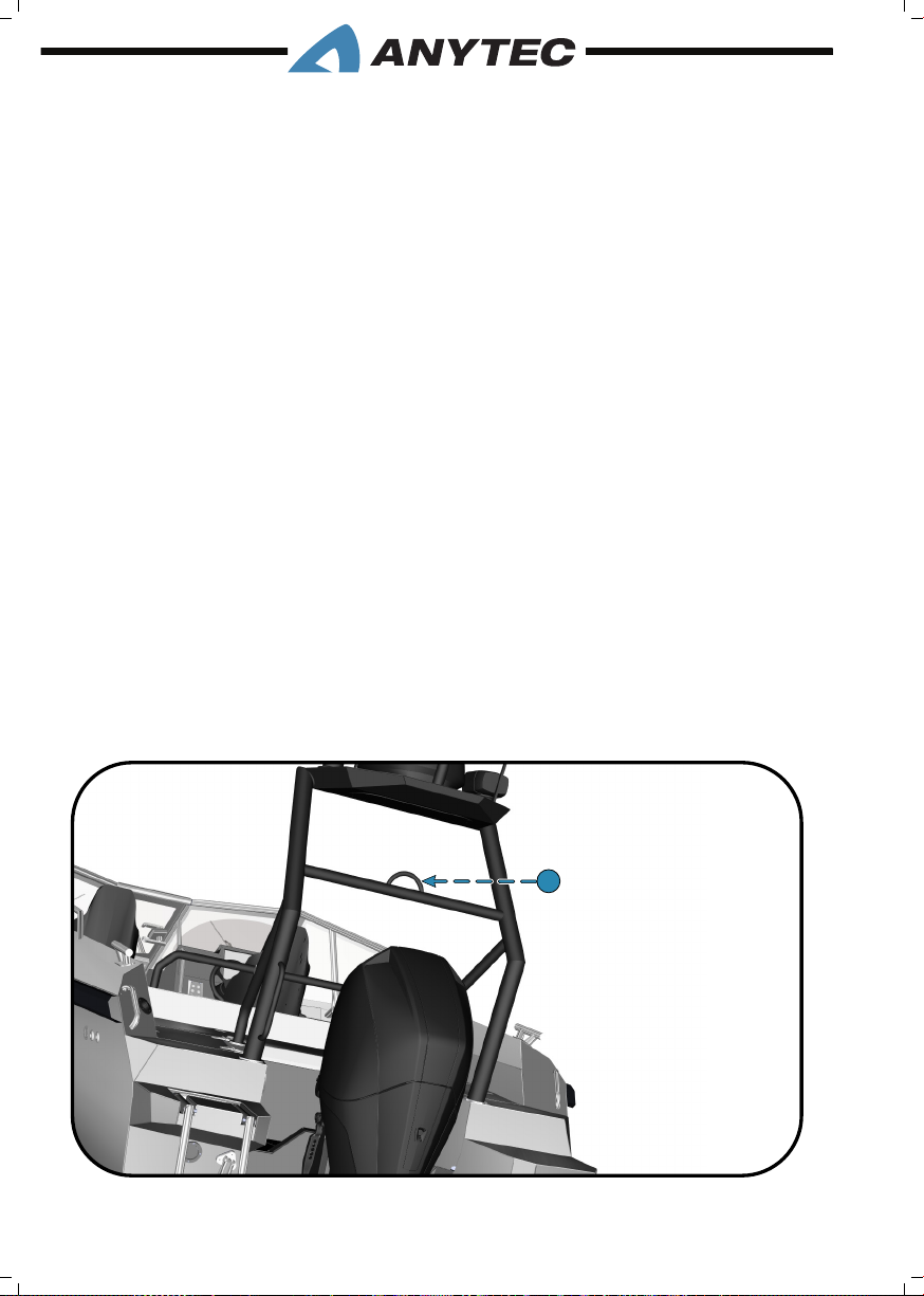
4.11 ADjustABLE sEAts, DRivER AnD nAviGAtOR
Standard seats
The standard seats have suspension built into the stand. The seats can be turned and ad-
justed up/down by pulling the large ap (can be pulled in 2 steps) below the seat. The seat
can also be adjusted back/forward by pulling the small ap below the seat.
Anytec performance suspension seats (optional)
The Anytec high performance suspension seats further absorb shocks and vibrations coming from rides in rough waters. They are especially developed and manufactured by Anytec
and include the top-of-the-line suspension units by Ohlin’s. The seat height can not be
adjusted during voyage, but can be adjusted manually by relocating the cylinder between
several xed positions. As for the standard seat, the seat can be turned and adjusted back/
forward by pulling the tab below the seat,
To adjust the optional performance seats spring preload, compression damping,
rebound damping and to adjust length of the shock absorber please refer to the
Ohlin’s owner manual. It is provided with the Anytec document bag.
4.12 WAtERspORt tOW ROpE AttAChMEnt
Your boat come equipped with an attachment point for watersport tow ropes, integrated
to the targa.
The attachment point is only to be used for water skiing wakeboarding or tubing. It is not
designed for towing boats, parachutes and kites or similar. Attach the tow rope around the
40 mm thick pipe, and inside the arc area. The purpose of the arc is only to prevent the line
to shift sideways, NOT to hold the rope.
1. Watersport tow rope attachment
4. SYSTEMS & COMPONENTS__PAGE 54
1
1
Page 63
Only tow water skis, watersport tubes or wakeboards. Do not tow parasails, kites, or other boats.
Do not tow more than one person at one time. Select a proper tow rope as a breaking rope may
snap back into the cockpit when released. Do not attach the rope to the arc, as it is only designed
to stop the rope from slipping sideways Failure to follow these guidelines may result in injury or
death.
4.13 WEBAstO hEAtER (OptiOnAL)
The Webasto heater is located in starboard pulpit under the helm. Its purpose is to provide
heat to the stern cockpit and to keep the front windows clean of fog and frost. It runs on
diesel fuel. The unit consists of a heater unit, a 10L diesel tank, air outlets below windows
and at feet level on both SB and PS pulpit, exhaust tting on freeboard and a control panel
on dash panel that operates the system.
Note that the PS pulpit storage where the heater tank is installed shall not be used for any
storage. This is very important to ensure safe operation and ventilation of the heater and
the tank. The hatch has a “no storage” sticker, if it is not visible anymore it shall be replaced.
Operation
Prior to use, make sure that the fuel tank is full. The 10L diesel tank, located in the PS pulpit
storage, can be accessed by opening the door. To ll the diesel tank, rst remove the strap
holding the tank in place. Next, remove the cap with the fuel pickup / return line and pull
the tank out of the boat. ALWAYS FILL THE TANK OUTSIDE OF THE BOAT. When lled,
re-install the cap, and secure the tank in the entertainment center. Visually check that fuel
lines and tank do not leak.
The heater is then operated using a controller which is located on the dash panel, see
chapter 3.11.
Fuel vapours can explode. Never smoke or be close to open ames or potential electrical sparks
while handling or lling up the petrol tank. Leaking fuel is a re and explosion hazard. Inspect the
fuel system annually to make sure that there are no leaks and corrosion in the system.
Do not obstruct or modify the ventilation system for air, fuel and exhaust gas. Never store any
luggage or other items in the hatch of the heater and heater tank!
Exhaust gas is HOT. Ensure that there is nothing that is susceptible to heat damage (i.e. ropes,
fenders, other boats) within 200mm of the exhaust outlet.
For complete instructions on operation and maintenance, we refer to the separate
OEM owner’s manual that was developed specically for this equipment. It is provided with the Anytec document bag.
4. SYSTEMS & COMPONENTS__PAGE 55
Page 64
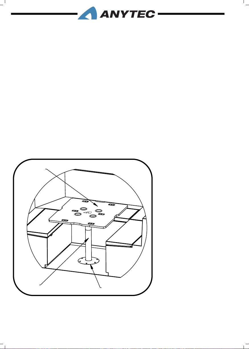
4.14 AuDiO & RADiO systEM (OptiOnAL)
Your boat may come equipped with Fusion audio and radio system, with several options
possible. The main unit is located under the helm, and marine speakers are installed at
suitable locations . It’s connected to the plotter and allows you easily change the settings,
volume, songs etc. on the plotter screen. The most basic settings are also available from
a small remote control panel on the dash (see 3.11). An optional USB port allows you to
connect an external music player for audio/music playback thru the audio system. Alternatively, you can playback audio/music via Bluetooth®.
For complete instructions on operation and maintenance, we refer to the separate
OEM owner’s manual that was developed specically for this equipment. It is provided with the Anytec document bag.
Your boat may be equipped with an Anytec table with aps and cup holders. To install the
table, rst remove the plastic cover located on the table base plate. Next, push and lock
the table leg into the base plate. Finally, place the table onto the table leg. When not in use,
the table can be stored in the stern cockpit U-sofa & storage.
4.15 COCkpit tABLE (OptiOnAL)
3
1. Table base
2. Table stand
3. Table top
2
4. SYSTEMS & COMPONENTS__PAGE 56
1
Page 65
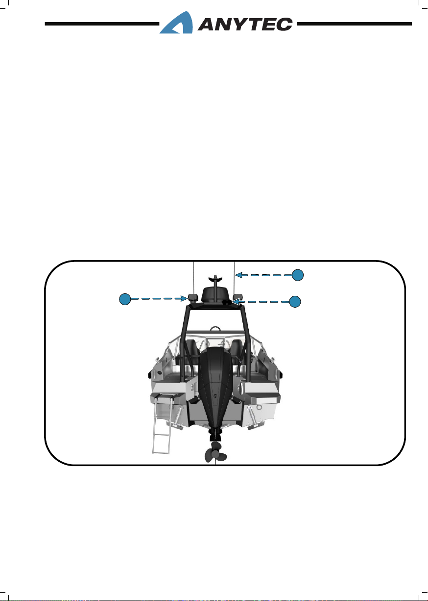
4.16 CAMERA With infRARED (OptiOnAL)
The boat may be delivered with one or two optional day & night vision camera(s) that
facilitates navigation and maneuvering of the boat. The camera(s) are connected to the
multifunction unit and operated using the screen.
The exact location and conguration can be customized, but the camera(s) are mostly
mounted on the targa (refer gure in chapter 4.22).
For complete instructions on operation and maintenance, we refer to the separate
OEM owner’s manual that was developed specically for this equipment. It is provided with the Anytec document bag.
4.17 sEARCh LiGht (OptiOnAL)
The boat may be delivered with an optional wireless remote controlled search light. Usual-
ly, the search light is located on targa for a better range of light (see the gure). It may help
you to navigate at night, and it can also be used as an onboard work light. Please note that
your night vision weakens if you are dazzled by strong lights, so be careful if you operate
the boat at night and use the search light with caution.
1
1
1
3
2
1
1. VHF antennas
2. IR cameras
3. Search light
4. SYSTEMS & COMPONENTS__PAGE 57
Page 66

For complete instructions on operation and maintenance, we refer to the separate
OEM owner’s manual that was developed specically for this equipment. It is provided with the Anytec document bag.
4.18 vhf RADiO (OptiOnAL)
The boat may be delivered with a waterproof VHF radio which allows you to reach coastguards, port authtorities and other boats by radio. Be careful to study the manual and
understand how to contact coastguard and send general call-for-help (mayday) messages.
The adjustable VHF antenna is located on the targa, and the VHF module with microphone
is located directly on the dashboard panel (see the gure)
For complete instructions on operation and maintenance, we refer to the separate
OEM owner’s manual that was developed specically for this equipment. It is provided with the Anytec document bag.
4. SYSTEMS & COMPONENTS__PAGE 58
Page 67

5. ELECTRICAL SYSTEMS
5.1 GEnERAL DEsCRiptiOn
Your boat is equipped with a 12 V DC electrical system, as standard powered by one battery. The alternator of the engine keeps the battery charged. The voltmeter screen located
on the Multifunctioal panel indicates the battery voltage (optionally also on the engine
instruments).
All cabling is done using pre-manufactured cable harnesses, specically adopted for this
boat model. All cable ends and consumers (e.g. bilge pump, winches, lights) are coded and
can be identied on the attached schematics.
All consumers are connected through fuses to the battery. The fuses are of automatic type,
and reset easily afetr identifying the problem. All fuses are individually marked on the boat
for easy trouble-shooting.
The complete system is controlled by the main switch, which can cut the power to all consumers except the bilge pump. The bilge pump has a permanent power supply, to function
at all times.
The main battery switch is installed on the fuse terminal in the stern sofa but can also be
remotely operated from the helm. When leaving the boat for longer periods, always turn
the main switch off to avoid battery drain.
Anytec has equipped the boat with empty spare circuits where Auxiliary Equipment (aftermarket products) can be installed. These are marked as AUX on the fuse panel, and on the
helm control panel. If you choose to use them, please make sure they are marked for easy
identication and that the electrical installation is professional.
Any modications to the electrical system must be made by experienced staff. Using the
hull as one pole ( positive or negative, for instance for earthing of consumers) will likely
cause major issues including risk of corrosion damages to the hull, and must be avoided at
all times. Batteries can generate high currents that can be fatal and cause sparks and res.
Make sure you always understand how the system works before you do any maintenance
or modications, such as disconnecting batteries, adding AUX equipment or repair work.
Always disconnect the power using the main switches, before any work on the electrical system.
Failure to do so may cause electric shocks, or sparks that can ignite fuel fumes. Always ventilate
areas with fuel or batteries before any work, and never use open ames in these areas.
5. ELECTRICAL SYSTEMS__PAGE 59
Page 68
1. The bilge pump may still draw power from the batteries, even if the switches are set to OFF
so that it can operate even if the boat is docked and unattended. In the worst case, the boat
may sink if left unattended for a long time without checking battery power, be particularly
observant in periods of heavy rains and winds.
2. When leaving the boat for long periods, always turn the main switches off to avoid battery
drain, especially in rainy periods. Failure to do so may hinder the bilge pump from working,
potentially causing the boat to sink in case of water leaks into the bilge. Never leave the boat
unattended for long periods, and check battery charge level regularly.
5.2 BAttERiEs & ChARGinG
In case of replacement, refer to your engine owner’s manual for exact battery requirements.
The battery should always be installed and secured within the battery box, to prevent that
they shift during voyage and potentially cause damages or even res. Protective terminal
covers must always be used (covering the battery +/- connecting points) to aviod shortcuts and sparks.
To remove the battery cables (for instance to replace batteries or bring them to a charging
station):
To remove the battery cables (for instance to replace batteries or bring them to a charging
station):
• Turn off all items drawing power from the battery.
• Turn the battery main switches to the LOCK OFF position.
• Remove the negative cable rst, then the positive cable.
• When re-installing batteries, always install the positive cable rst, then the negative
cable.
Protective battery terminal covers must always be used (covering the battery +/- connecting
points) to avoid short-cuts and sparks. Batteries must always be installed and secured in xed
installed battery boxes.
5.3 BAttERy sELECtOR sWitCh
Service and starting battery:
Your vessel as standard is equipped with a main switch at the fuse panel. When you turn
ON the battery switch, power is provided to the engine and consumers.
5. ELECTRICAL SYSTEMS__PAGE 60
Page 69
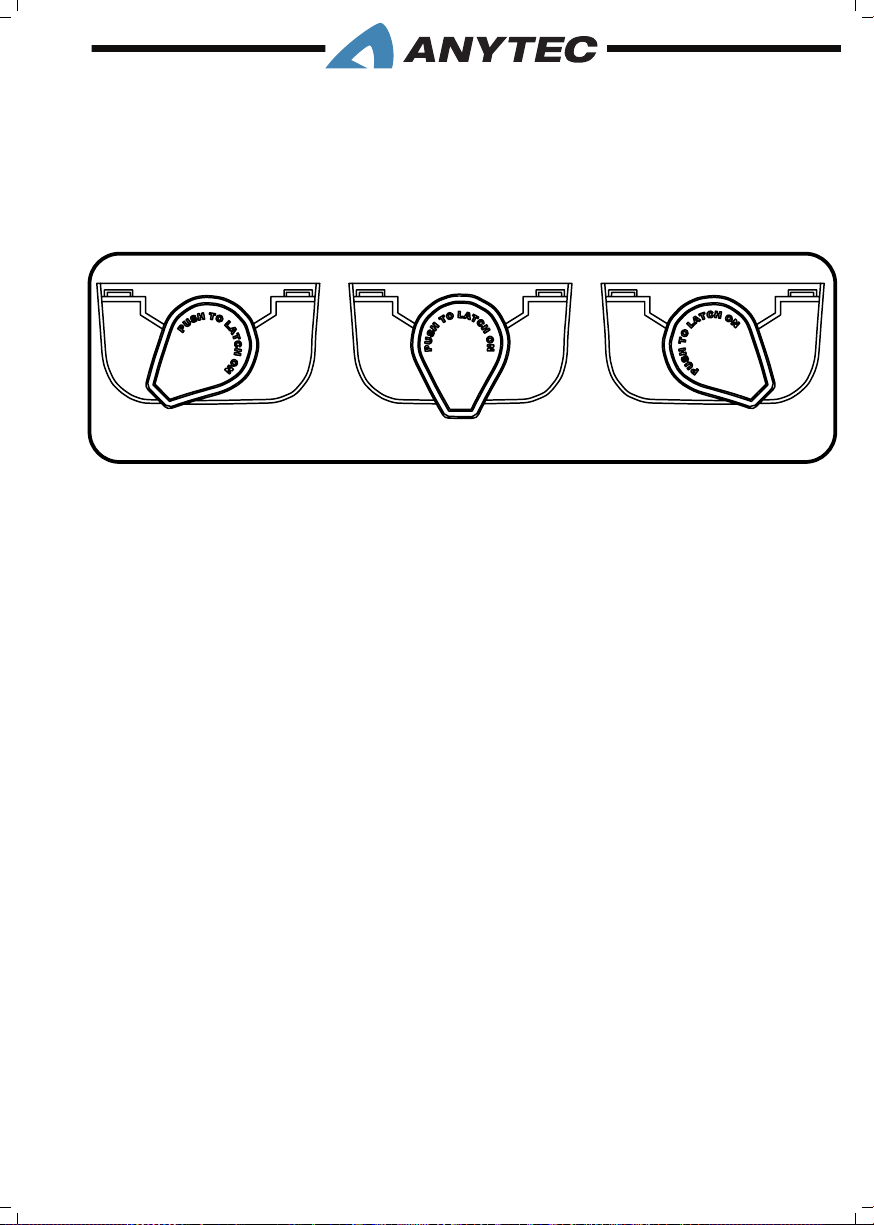
When leaving the boat for long periods and when doing maintenance on equipment/parts
connected to the electrical system, turn the switch to the LOCK OFF position. See also
the gure in chapter 5.4.
MAIN SWITCH MANUAL OVERRIDE
1
1. Remote/On position
2. Off position
3. Lock off position
2
3
Principal gure only
5.4 CiRCuit AnD MAin BREAkER pAnEL
Your boat is equipped with a main battery breaker and individual circuit breakers protecting the DC electrical system. The panel is found in the mid sofa storage area. The fuses can
be reset if they trip, by pushing the buttons. They are individually marked.
5. ELECTRICAL SYSTEMS__PAGE 61
Page 70
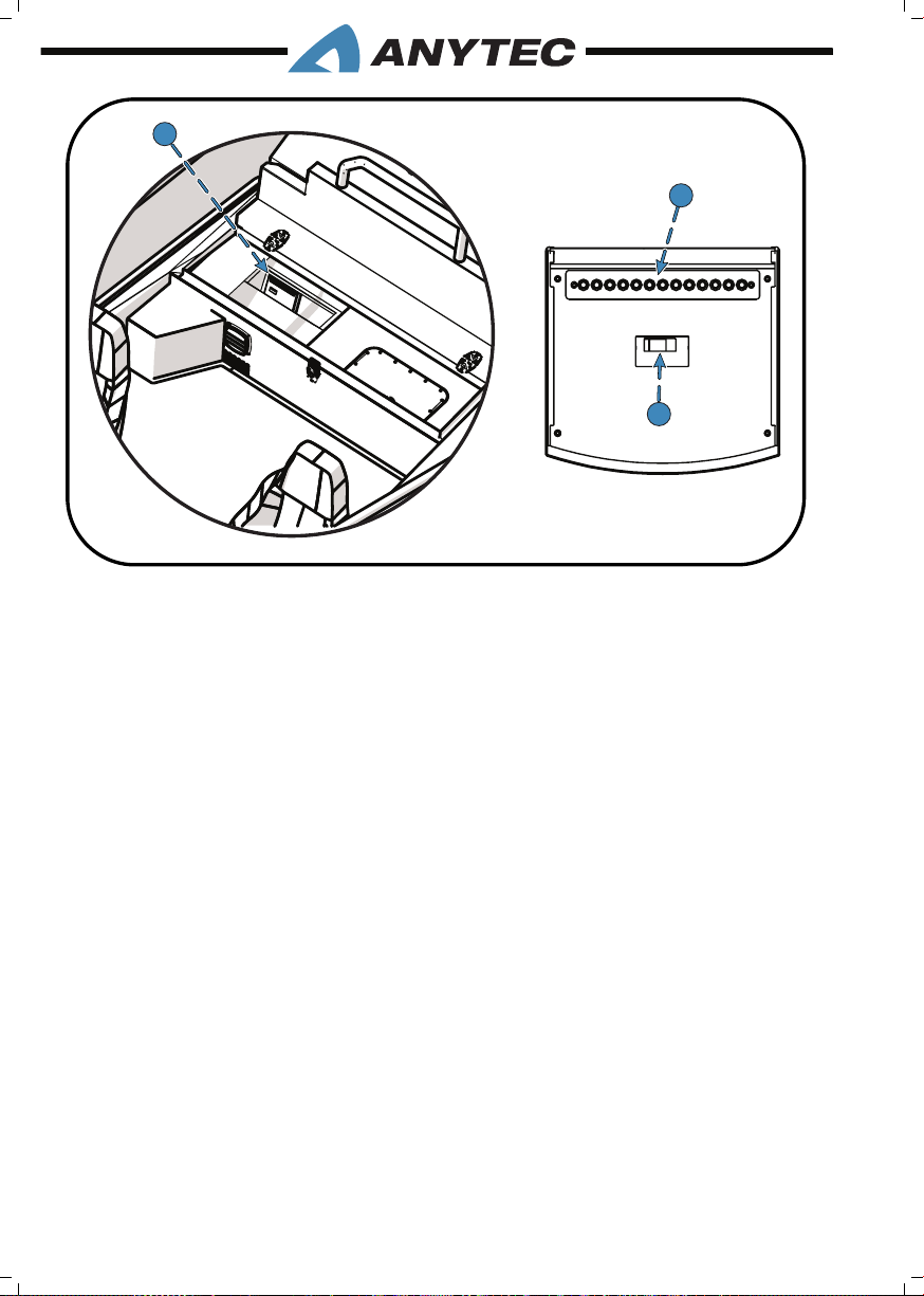
1. Main panel location
16
1
2
3
2. Circuit breakers
3. Battery main switch
5.5 ELECtRiCAL sChEMAtiCs
Electrical schematics are included as printed attachments to this manual. They can also be
obtained from your dealer or Anytec if they are lost. These electrical schematics can be
used for technical reference and professional service technicians. If you lack professional
skills for this kind of system, contact your local authorised Anytec dealer for help.
5. ELECTRICAL SYSTEMS__PAGE 62
Page 71
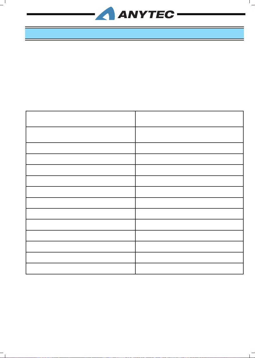
6. MAINTENANCE
Routine inspection, service and maintenance of your boat, systems and components are
vital to assure your safety and will prolong the life of your boat.
Maintenance of Anytec manufactured parts are described in detail in this chapter.
Specialists manufacture other parts such as engine and navigation systems. To ensure the
best possible instructions, we sometimes refer to the specic OEM maintenance manuals.
These are provided with the boat (please check the Anytec document bag). This applies
to the following components (reference is given to the operations chapter in this boat
manual):
Component/system with separate manuals
Multifunction Unit (navigation/communication)
Engine controls Chapter 4.6
Engine power steering Chapter 4.2
Audio system (optional) Chapter 4.14
Fire extinguisher Chapter 2.4.1
Heater (optional) Chapter 4.13
Trim control system Chapter 4.7
Bilge pumps Chapter 4.4
Navigation lights Chapter 4.3
Electrical system, switches and battery Chapter 5
Search light (option) Chapter 4.17
Camera with Infrared (option) Chapter 4.16
VHF radio (radio (option) Chapter 4.18
Reference chapter in this owner’s manual
Chapter 4.5
The interval between necessary service and maintenance is highly variable, depending on
the environment in which your boat will be used, and how much you use it. For example,
corrosion of boat parts and components occur far more rapidly in a salt water environment than on a boat which is used in fresh water.
6. MAINTENANCE__PAGE 63
Page 72
This section provides only general guidelines for the care and cleaning of your boat. It is
your responsibility to determine whether maintenance and care intervals need to be accelerated due to your boat usage and operating environment. If you have any question regarding maintenance of your boat, contact your local Anytec dealer for additional assistance.
While using chemicals, read all information from the manufacturer regarding safety and handling of
the material. Wear proper protective equipment to ensure personal safety. Work only in well-ven-
tilated areas and keep all chemicals away from open ames.
1. Refer to the individual manufacturer’s manuals, which can be found in the Owner’s Manual
packet, for care and maintenance of equipment and components. In some cases, failure to do
so could void the warranty.
2. If chemicals are used during maintenance, be careful to follow environmental regulations and
good practices, in particular, if they may be released to water.
6.1 fuEL systEM
Long periods of storage or non-use, common to boats, create unique problems. When
preparing to store a boat for extended periods, of two months or more, it is best to remove all fuel from the tank completely. The fuel remove plug is installed on the fuel tank
inspection hatch. You can use this hole for putting a hose from any portable bilge pump
to remove the fuel. If it is not possible to remove the fuel, maintaining a full tank of fuel is
recommended to prevent condensation of humid air.
If water enters the fuel system, it has to be drained completely and refueled with fresh fuel.
Water may be detected by inspecting the fuel water separator lter (optional) or by signs
of uneven engine operation / jumpy rpm / starting problems.
At least once in a year, carefully inspect all fuel and ventilation lines and hoses. Check for
signs of leaks along them and carefully check the connections at each end.
6.2 huLL, DECk, RAiLs & supERstRuCtuREs
Freshwater, saltwater and water temperature can all affect the types of marine growth
that you nd on your boat’s surfaces. Any marine growth can affect the boat’s performance
and overall look. Keep the surfaces clean using water and a soft sponge /brush, or mild
detergents.
In particular, you might notice algae or slime growth on the hull below water level. The
below-water growth should be cleaned immediately after the boat has been removed from
the water. If the growth is allowed to dry it will be much harder to remove.
6. MAINTENANCE__PAGE 64
Page 73

At least yearly, check for damages to hull and superstructures such as dents, cracks and
corrosion. Carefully check that swim/rescue ladder, handrails, cleats and secure/bow eyes
are not loose and has no cracks or corrosion damages.
6.2.1 Aluminium treatment M-400® maintenance & principle
Anytec boats have a patented surface treatment on all aluminium surfaces, called M-400®.
The treatment bonds to the aluminium and strengthens its characteristics, giving the boat
hull a fantastic shine while preventing oxidation.M-400 chemical resistance is signicantly
higher than untreated aluminium.
We recommend regular rinse with clean fresh water on M400 treated surfaces. If you
do not allow aggressive substances to “burn”, the surface works relatively self-washing
(hydrophobic) with fresh water. In that case, collections of salts and soils are washed away.
On untreated aluminium, these salt oxidise the aluminium and thus bound to the surface.
On surfaces that are in the water (e.g. below the water line), a mild brush can be used
regularly to easily remove algae and the like, which mostly cannot get a good grip on the
M400, yet smooth/shiny surfaces attract them. On other surfaces, a mild sponge can be
used in combination with a mild (pH-neutral) shampoo, followed by a rinse. Regular car
shampoos work great. If desired, the M400 can be waxed and polished like a car. However
always avoid abrasive rubbing as this may damage the thin layer’s properties.
Despite the strong protection of the surfaces, please keep in mind that the protective layer
is very thin. Just like a ne ceramic frying pan, you should choose the right tools and means
for cleaning. Avoid aggressive chemicals and salt dries/burns in the surface, as they will
become difcult to remove over time. The use of abrasive methods for washing (such as
polishing discs or sponges) may gradually wear down the surface and its protection. Strong
basic chemicals are directly oxidising on aluminium and should, therefore, be avoided in any
case, although the M400 is signicantly better than pure aluminium. The acid resistance of
the M400 is relatively high, despite the thin layer. However, as acids are also highly corrosive
on pure aluminium, these should also be avoided.
After many years of use, or in case of damages to surfaces such as hull repairs, the treatment may be renewed. To get a good result, the complete hull should be polished and
treated again. As a minimum at least full outside surfaces and full inside surfaces should
be treated, as partial treatments may result in a bad visual impression (colour and surface
variations). Contact your Anytec dealer for further details.
6.2.2 Hull below water, anti-fouling treatment
The hull below water can be better protected by applying special hull anti-fouling, In particular when the boat is used in salt water areas. It is essential to choose the correct type
of primer and top coat, suitable for aluminium hulls and your local conditions.
If the boat was delivered with anti-fouling from the factory (optional), Anytec have used
the following products:
6. MAINTENANCE__PAGE 65
Page 74
• Primer: International Intergard 563 (white)
• Glue for anti-fouling: International Intergard 263 (grey)
• Anti-fouling: International Trilux 33 (black)
Consult with your local dealer as condition varies from water to water and is regulated by
local or national environmental regulations.
Do not apply any paint to zinc anodes, log sensor or trim tabs. Do not apply paints or lubricants
including copper on aluminium parts. Always follow the instructions of paint manufacturers.
Type of anti-fouling paint allowed may vary by region and country, always check local regulations.
6.2.3 Anodes for prevention of galvanic corrosion
One of the most important maintenance tasks when owning a boat is making sure you
protect the hull and engine from electrolytic corrosion. This can otherwise quickly create
serious damages. Anytec boats are therefore equipped with sacricial anodes, made from
zinc, which are designed to corrode instead of the boat and the engine. They are mounted
at the bottom recess (refer gure).
The anodes must be inspected annually and renewed if more than 50% are wasted. It is
important to inspect the working surface of the sacricial anode to ensure that it is free of
paint and chalky corrosion deposits and particularly very important on the contact surface
between the anode and the hull.
Your engine is likely also equipped with anodes that need to be maintained, refer engine
manual for further details.
Neglect to replace the boat zinc anodes in time can cause major damages to the boat hull and
engine!
Do not apply any paint to zinc anodes and ensure that the surface between the anodes and the
hull is metal clean when replacing and inspecting the anodes.
Several zinc anodes may be mounted directly on engine. Please contact the manufacturer or dealer
to check the replacement time of these anodes.
6. MAINTENANCE__PAGE 66
Page 75
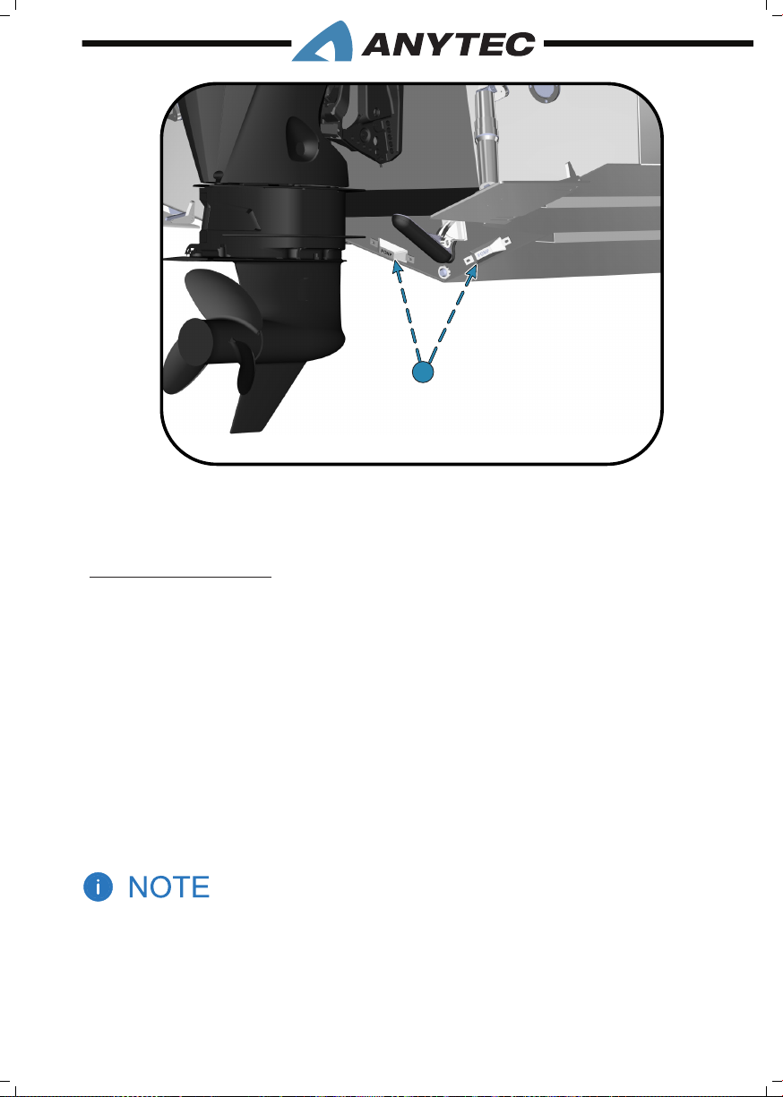
1. Zinc sacrice anodes
1
6.3 COMpOnEnt MAintEnAnCE
6.3.1 Stainless steel
Stainless steel is strong and corrosion resistant but still requires frequent routine cleaning
to maintain the surface nish.
Anytec recommends that you wash stainless steel components with mild soap and cold
or lukewarm water after every use of the boat. If added protection is necessary, apply a
cleaning wax.
Even the nest cleaning powders can scratch or burnish a mill-rolled surface. On polished
nishes, rubbing or wiping should be done in the direction of the polish lines, not across
them.
Crevice corrosion is a brownish colouring which occurs where impurities in water and air
cause two pieces of stainless hardware meet. It can be easily cleaned with a good grade
marine polish using a sponge, cloth or small bristled brush (for nooks and crannies).
1. The cleaner your stainless steel can be kept, the greater the assurance of optimum corrosion
resistance. Without proper care even the best stainless steel will corrode overtime.
2. Never use abrasive cleaners, detergents or soft scrub type cleaners to clean stainless steel.
Never use abrasive pads, brushes or sponges to attempt to remove stubborn stains. Never
use strong solvents or detergents which contain chlorine, and never use silver cleaners.
6. MAINTENANCE__PAGE 67
Page 76

6.3.2 Cushions
Saltwater, salt residue, dirt, ultra-violet rays etc., take their toll on vinyl and nylon products
causing them to lose their lustre and texture. To clean, remove ordinary dirt and smudges
with a mild soap and water solution. Rinse the cleaned area with fresh water and dry with
a clean, soft, lint-free cloth or towel.
Your cushions are not waterproof. They are constructed of open-cell foam and which
absorb and hold water. Do not leave the cushions in standing water or exposed to heavy,
prolonged rain. If, in the event your cushions become waterlogged, remove the foam from
the cushion, press as much water as you can from the foam and allow to air dry. To prevent
mildew, keep the vinyl dry and make sure that moisture does not accumulate between the
cushions when stored. Do not store until they are completely dry.
6.3.3 Canopy
Canopy fabric
Chang, bre wear from dirt and grit and deterioration from ultraviolet light can cause
your canopy to degrade over time. The fabric should be cleaned regularly before substances such as dirt, pollen, etc., are allowed to accumulate on and become embedded in the
fabric. The canopy can be cleaned without being removed from the installation.
After each use, especially if used in salt water areas; rinse the canopy completely with fresh
water (cold water if available). On a regular basis, brush off any loose dirt, pollen, etc., and
hose down with water and then clean with a mild solution of a natural soap in lukewarm
water (maximum 38°C). Only use soft sponges and brushes. Allow the canopy to soak;
however, do not let the soap dry. Let the canopy dry completely. Do not store any of the
pieces while wet. In most environments, a thorough cleaning and fabric treatment is needed every two to four years. The canopy is then removed and sent to a company specialised
in canopy cleaning and restoring work.
Chemical treatments of the fabric can improve the resistance to ultraviolet light and water.
Consult your Anytec dealer or canopy experts for advice. Be careful to not treat canopy
windows with such chemicals.
Zippers & Hardware
Lubricate zippers and fasteners periodically with a clear silicone-based zipper lubricant,
at least every season. In the absence of silicone lubricants, a wax candle can be used to
lubricate the zipper track. Replace any missing fasteners or any fasteners showing signs of
corrosion. Keeping the zipper lubricated is an easy way to extend the lifetime and make
canopy operation easier.
6. MAINTENANCE__PAGE 68
Page 77
Canopy Windows
Rinse vinyl windows thoroughly with clean water to remove any dust, dirt particles, salt
water or environmental agents. This should be done frequently to avoid build-up of salt
water, dirt and other environmental contaminants. After a rinse, use a soft non-abrasive
cloth and wash windows inside and out with a mild natural soap and water solution. Rinse
completely with cold water before the soap dries. Dry the window with a soft cloth or
chamois to prevent water spots. Polish with a separate cloth.
Do not use other chemicals unless these are specically made for vinyl windows and well
proven; consult your dealer for advice.
Never use regular window cleaners, detergents, abrasives, petroleum based products, or alcohol
to clean your canopy fabric or vinyl windows. Do not handle vinyl with sunscreen on your hands.
Sunscreen may permanently cloud the vinyl.
6.3.4 Tempered glass windows
First thoroughly rinse with clean water. Then if needed, use commercially available glass
cleaners or a mixture of fresh water and vinegar to clean your glass windows. Dry with a
soft terry cloth towel or chamois.
DO NOT use abrasives, harsh chemicals, or metal scrapers on the glass.
6.3.5 Fender list
The fender list has a D-shape and is pressed and glued against the hull. As a fender, it will
eventually have physical contact with other boats, docks and so on. Such contact result in
scratches, small deformations and some friction marks. This is natural and could be left
unattended as long as the fender is functional and well attached to the hull.
If the fender is dirty or discoloured, use regular mild detergents like boat shampoo and a
soft brush. If the fender looks faded, a treatment with “tire/bumper shine” or similar care
products for rubber can be used. Ask your Anytec dealer for advice if you are uncertain.
6.3.6 Plastic panels
Use only regular mild detergents like boat shampoo and a soft sponge or rag for cleaning.
Do not use polish and other abrasive chemicals and tools as they may ruin the surface.
6.3.7 Hinges and latches
The hinges and latches do not require any periodical maintenance and are grease-free.
They can be cleaned with regular detergents. Some of the latches for storage hatches are
adjustable to compensate for wear of seals of the hatches. Loosen the bolts that hold the
latch in place and adjust it. The holes are oval to allow for easy adjustments. Adjust it so
that the hatch closes rmly against the seal and thus is watertight.
6. MAINTENANCE__PAGE 69
Page 78

6.3.8 MOB rescue & swim ladder
The ladder is a safety device, and lack of maintenance may make it hard or impossible to
use safely. It is important to check the function of the ladder regularly. Check at least yearly
that it is properly fastened to the boat and has no cracks or corrosion damages. Check the
condition and function of the nylon clip that secures the ladder in stored position.
6.3.9 Painted surfaces
Certain surfaces as well as the targa structure are painted with black industrial-class paint.
They can be washed with regular mild detergents like boat shampoo and a soft sponge or
rag. Be careful with using polish and other abrasive chemicals and tools as they may ruin
the surface. As all with all dark paints, they will oxide and fade over time. However, as the
painted surfaces are of aluminum, there is no corrosion. Re-painting may be needed for
visual impression only.
6.4 WintER stORAGE/spRinG pREpARAtiOns
Preparing boats for winter storage are subject to your location. In cold climates, always
have your boat hoisted in good time before the water freezes. This is a good time to perform all yearly maintenance, repair and inspection procedures. Even if your boat is used
around the year, a yearly maintenance period is recommended and shall follow the same
routines as specied below except when marked with a *.
6.4.1 Measures before winter storage
• Check the engine owner’s manual and carefully follow the instructions.
• *Lift your boat out from water well before ice formation. Your boat is not dimensioned
against sailing or storage in ice.
• Hoist the boat. Wash the bottom of the boat immediately afterwards. Algae and slime
easily comes if they are not let to dry.
• Remove the bottom drain plug (refer chapter 3.10) and leave the drain open.
• Check the condition of the hull. Repair damages directly or the next spring before
launching the boat.
• *When preparing to store a boat for extended periods, please refer chapter 6.1(Fuel
System).
• Ensure that the hull has sufcient support to avoid damages or instability. If uncertain,
always consult experts such as your dealer.
• Follow the maintenance instructions given in the engine manual. We recommend that
you hire an authorised service company to ensure a safe and reliable operation of the
engine. Do not forget to service the engine controls and steering system.
6. MAINTENANCE__PAGE 70
Page 79

• Carryout maintenance operation on other accessories and equipment as described
in this chapter and in the respective OEM manuals.
• If your boat is stored outside or in a humid place during the winter, remove electronic
instruments, the textiles, the canopy, cushions, seats and other equipment that may
corrode or become mouldy in moist conditions, and store it in a dry place.
• Spray the electrical connectors with a suitable moisture repellent antioxidant.
• *Remove batteries and store them in a warm, dry place. Charge them at least twice
during the winter. Spray the electrical connectors with a suitable moisture repellent
antioxidant.
• Check conditions of anodes (refer chapter 6.2.3). Replace if needed. Clean the
surface between anodes and hull to ensure good metallic contact. Never paint them!
• *Cover your boat so that snow and water will not gather inside. Always make sure
that there is enough ventilation and avoid direct contact between the boat and the
covering material/canvas as it may damage the boat due to friction and oxidation.
6.4.2 Measures after winter storage
• Check the engine owner’s manual and carefully follow the instructions.
• *Reinstall freshly charged batteries and check voltage.
• Refuel the boat.
• *Install any electronic instruments, textiles and other equipment that was removed
before winter storage. Test them after installation or at rst time in sea before leaving
the shore.
• Reinstall bottom drain plug.
• Check the condition of the hull including strong points/cleats. Repair damages directly.
Refresh anti-fouling paint if it has been used before, or consider adding new paint if
the boat is moved to new waters (refer chapter 6.2.2.).
• Inspect and test petrol, diesel and gas systems including hoses and connectors
(engine, any optional heater, stove or similar): Check for any signs of wear & tear and
leakage (leaks, stains, smell).
• Carryout maintenance and functional tests on other accessories and equipment as
described in this chapter and the respective OEM manuals.
• Pay extra attention to the condition and function of safety and maneuvering
equipment like steering system, bilge pumps, emergency switch function, electrical
systems, function of instruments, MOB/ladder function, condition of seals at doors
and hatches, navigation lights.
6. MAINTENANCE__PAGE 71
Page 80

6.5 spARE pARts & sERviCE
To ensure the best possible performance, safety and lifetime of your Anytec boat, it is
important only to use high-quality spare parts that are suitable and approved for your spe-
cic boat application. Failure to do so may jeopardise the safety, lifetime and performance.
Anytec offers the parts through the dealer network.
Parts and accessories tted on the boat are subject to modications without prior notice.
Your dealer will be able to investigate if such is the case for your specic needs. Your dealer
can also support you with qualied service, upgrade and modication work, using their
own or Anytec specialists.
If you have any questions regarding parts, accessories or services, please contact an Anytec
dealer.
For best possible service, always provide your CIN number (unique hull number) as it
will assure that the parts and services are specic for your individual boat. For location of
the CIN number, please refer chapter 1.3.
6. MAINTENANCE__PAGE 72
Page 81

7. ATTACHMENTS
List of the attached documents/drawings, to be found in the Anytec manual holder and
Anytec shoulder bag:
• Electrical diagrams
• Owner’s manuals for components (as referenced to in the Anytec owner’s manual)
• Final Quality Approval
• Authorised Installation Certicate
• Declaration of Conformity of recreational craft
• Delivery note with SecurMark bar code
• Canopy installation guide
7. ATTACHMENTS__PAGE 73
Page 82
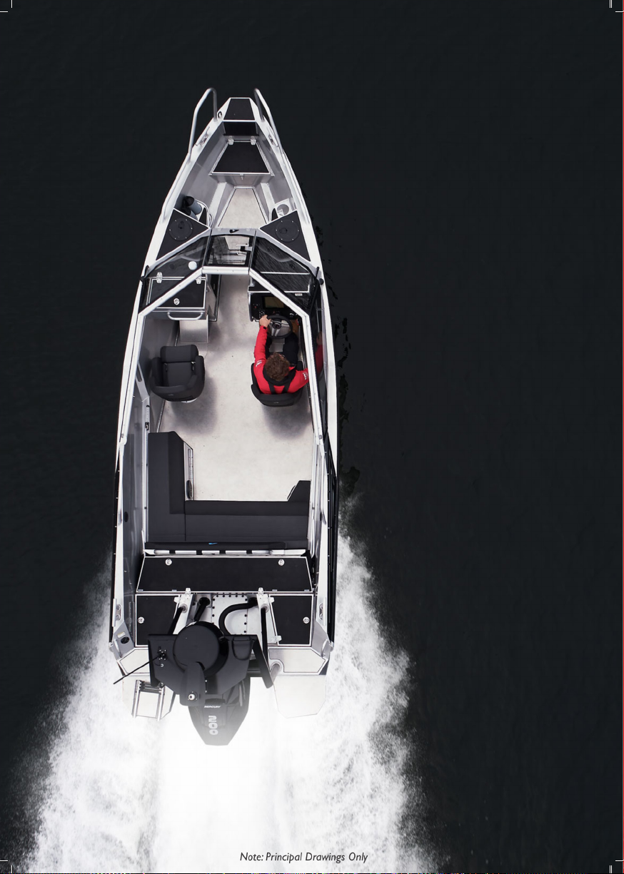
Page 83

OW NE R’ S MANU AL AN YTEC A21
Anytec Sweden reserves the right for any typographical
errors and reserves the right to make changes. Boats in
this owner’s manual may include optional equipment. The
content of this manual is protected by copyright.
All rights reserved
© Anytec Sweden AB
 Loading...