

Page 1
Anyload Transducer Co. Ltd
Website: www.anyload.com
Email: [email protected]
Fax: +1 866 612 9088
North America Toll Free: 1-855-ANYLOAD (269 5623)
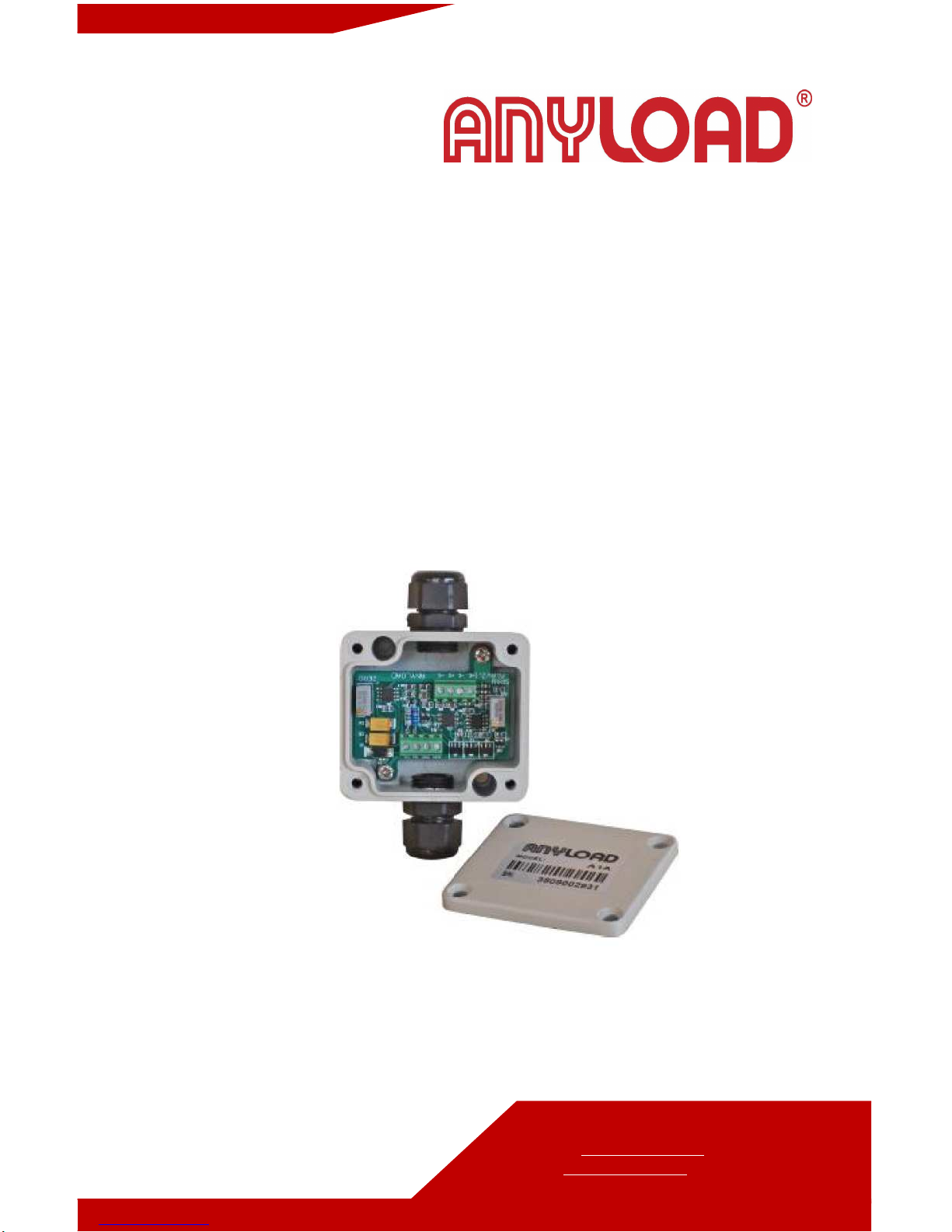
A1A
Load Cell Amplifier
Product Manual
(V1611)
Page 2

1 |
ANYLOAD A1A Amplifier Product Manual (V1611)
TABLE OF CONTENTS
1. Introduction 2
2. Installation 2
3. Connection Diagram 2
4. Specifications 3
5. Calibration 3
• Zero Calibration
• Span Calibration
6. Operation 4
7. Troubleshooting 4
Page 3

2 |
ANYLOAD A1A Amplifier Product Manual (V1611)
1. Introduction
Thank you for choosing Anyload A1A load cell amplifier. A1A strain gage
amplifier provides load cell and transducer signal conditioning. It is designed for
converting mV signal from load cell output into a 4~20mA or 0~10V signal. The
A1A strain gage amplifier is DC powered and can drive up to 2 x 350Ω load cells
or 4 X 700Ω load cells. It can be connected directly to 1 load cell or to several
load cells through a junction box. The amplifier is housed in an aluminum
casting enclosure and has 2 through holes for easy installation. This manual
provides the installation, operation and calibration procedures of the product.
2. Installation
Only simple tools like small size slotted screw driver and Philips screwdriver are
required for connecting cables during installation, adjusting the unit during
calibration and installation of enclosure cover.
3. Connection Diagram
Fig1.Connection Diagram
From Amplifier to 24V DC Power and 0~10V/4~20mA output signal:
Vo: Output Voltage Signal 0~10V
Io: Output Current Signal 4~20mA
Vs: Input 24V DC Power
GND: Ground
Page 4

3 |
ANYLOAD A1A Amplifier Product Manual (V1611)
From Load Cell to Amplifier:
+S:+Output mV Signal
-S:-Output mV Signal
+E:+Excitation
-E: -Excitation
4. Specifications
Power Supply: 24V DC }10%,<3W Maximum Input Voltage:30V DC
Input Signal: 0~30mV Maximum Output Current: 40mA
Output Signal: 0~10V/4~20mA Maximum Output Voltage: 15V
Operating Temperature: -10°C~40°C
Operating Humidity : ≤90%R.H.
5. Calibration
The calibration of A1A consists of Zero Calibration and Span Calibration:
5.1 Zero Calibration
Step1.Remove all load from the scale platform. If the scale require hooks or
chains (tare weight), place the hooks or chains into the scale for zero
calibration.
Step2.Adjust ZERO variable resistor to an output of 0V or 4mA.
(Note: Tare weight shall not exceed 30% of full load)
5.2 Span Calibration
Step1.Place full load into the scale.
Step2. Adjust SPAN variable resistor to an output of 10V or 20mA.
(Note: It’s recommended to repeat adjustment in Step 2 of Section 5.2 above
three times.)
6. Operation
6.1 Except during calibration, always keep the enclosure cover on and ensure
the seal is properly fitted when installing the cover.
6.2 Always keep the amplifier clean from dirt to avoid affecting the values of
the ZERO and SPAN variable resistors.
Page 5

4 |
ANYLOAD A1A Amplifier Product Manual (V1611)
6.3 For stable amplifier signal output, always use safe and reliable DC power
supply.
6.4 When output reading changes, re-calibrate the amplifier according
to Section 5, Calibration.
7. Troubleshooting
7.1 No output from the amplifier: Check all wire connections and the DC power
supply.
7.2 Output signal is abnormal: Re-calibrate according to Section 5, Calibration.
7.3 Problem cannot be resolved: Contact supplier
 Loading...