


AAnnyybbuuss®®XX--ggaatteewwaayy
USER MANUAL
HMSI-27-262 4.0 en-US ENGLISH
™™

Important User Information
Disclaimer
The information in this document is for informational purposes only. Please inform HMS Industrial Networks of any
inaccuracies or omissions found in this document. HMS Industrial Networks disclaims any responsibility or liability
for any errors that may appear in this document.
HMS Industrial Networks reserves the right to modify its products in line with its policy of continuous product
development. The information in this document shall therefore not be construed as a commitment on the part of
HMS Industrial Networks and is subject to change without notice. HMS Industrial Networks makes no commitment
to update or keep current the information in this document.
The data, examples and illustrations found in this document are included for illustrative purposes and are only
intended to help improve understanding of the functionality and handling of the product. In view of the wide range
of possible applications of the product, and because of the many variables and requirements associated with any
particular implementation, HMS Industrial Networks cannot assume responsibility or liability for actual use based on
the data, examples or illustrations included in this document nor for any damages incurred during installation of the
product. Those responsible for the use of the product must acquire sufficient knowledge in order to ensure that the
product is used correctly in their specific application and that the application meets all performance and safety
requirements including any applicable laws, regulations, codes and standards. Further, HMS Industrial Networks will
under no circumstances assume liability or responsibility for any problems that may arise as a result from the use of
undocumented features or functional side effects found outside the documented scope of the product. The effects
caused by any direct or indirect use of such aspects of the product are undefined and may include e.g. compatibility
issues and stability issues.
Anybus®X-gateway™User Manual
HMSI-27-262 4.0 en-US

Table of Contents
Page
1 Preface ................................................................................................................................. 3
1.1 About This Document ....................................................................................................... 3
1.2 Document history ............................................................................................................ 3
1.3 Document Conventions ..................................................................................................... 4
1.4 Document-specific Conventions..........................................................................................4
2 Description .......................................................................................................................... 5
2.1 Introduction................................................................................. ....... ....... ....... ....... ....... 5
2.2 Data Exchange........................... ....... ....... ....... ....... ....... ...................................................6
2.3 Status and Diagnostics . ........................................................ ....... ....... ....... ....... ....... ....... ... 7
2.4 Controlling the X-gateway from the Network . ....... ....... ......................................................... 9
2.5 Error Handling .................. ....... ....... ....... ....... ....... ....... ....... ....... .......................................9
2.6 Data Mapping Examples .................................................................................................. 10
3 Installation......................................................................................................................... 11
3.1 DIN Rail Mount .............................................................................................................. 11
3.2 Connectors and Indicators ............................................................................................... 12
4 Anybus Configuration Manager ....................................................................................... 13
4.1 Introduction................................................................................. ....... ....... ....... ....... ..... 13
4.2 Setup ................................. ....... ....... ....... ....... ....... ....... ....... ....... ....... ....... ....... ....... ...... 14
4.3 Configuration .............................................................................................. ....... ....... .... 14
A Technical Data ................................................................................................................... 15
Anybus®X-gateway™User Manual
HMSI-27-262 4.0 en-US

This page intentionally left blank

Preface 3 (16)
1 Preface
1.1 About This Document
This document describes the functions and general configuration of the Anybus X-gateway.
Documentation and software for the specific fieldbus and Ethernet network interfaces can be
downloaded from www.anybus.com/support.
1.2 Document history
Version
1.00 2004-04-02
2.00 2014-05-01
2.10 2014-08-26
3.0 2017-01-23 Major rewrite
3.1 2018-03-23
4.0 2019-03-19
Date
Description
First release
Major update
Compliance information update
Minor update
Rebranding update, some graphics updated
Removed certification info (now in datasheet only)
This document now replaces SCM-1202-038.
®
Anybus
X-gateway™User Manual
HMSI-27-262 4.0 en-US
Preface 4 (16)
1.3 Document Conventions
Ordered lists are used for instructions that must be carried out in sequence:
1. First do this
2. Then do this
Unordered (bulleted) lists are used for:
• Itemized information
• Instructions that can be carried out in any order
...and for action-result type instructions:
► This action...
→ leads to this result
Bold typeface indicates interactive parts such as connectors and switches on the hardware, or
menus and buttons in a graphical user interface.
Monospaced text is used to indicate program code and other
kinds of data input/output such as configuration scripts.
This is a cross-reference within this document: Document Conventions, p. 4
This is an external link (URL): www.hms-networks.com
This is additional information which may facilitate installation and/or operation.
This instruction must be followed to avoid a risk of reduced functionality and/or damage
to the equipment, or to avoid a network security risk.
Caution
This instruction must be followed to avoid a risk of personal injury.
WARNING
This instruction must be followed to avoid a risk of death or serious injury.
1.4 Document-specific Conventions
The following conventions are used specifically in this document:
• Hexadecimal values are written as NNNNh (the suffix h indicates hexadecimal notation).
• 16 and 32 bit values are stored in Motorola (big endian) format unless otherwise stated.
Anybus®X-gateway™User Manual
HMSI-27-262 4.0 en-US

Description
2 Description
2.1 Introduction
The Anybus X-gateway consists of two Anybus fieldbus or Ethernet network interface modules
and an intelligent gateway platform which transfers data between the two networks.
The X-gateway can be configured via a USB port using a Windows-based application, Anybus
Configuration Manager. The on-board network interfaces are normally configured from the
respective networks, using third-party configuration tools.
5 (16)
Fig. 1 Anybus X-gateway concept overview
This document describes only the gateway platform. The network interfaces are described in
their own documentation.
Anybus®X-gateway™User Manual
HMSI-27-262 4.0 en-US

Description
2.2 Data Exchange
Fig. 2 Anybus X-gateway data exchange
The terminology and definitions used for different types of data vary between different network
types. Most networks distinguish between fast, cyclical I/O data, and less time-critical acyclic
data. In the Anybus X-gateway these types of data are generally referred to respectively as I/O
Data and Parameter Data.
6 (16)
Each of the two network interfaces exchanges data on its network through its own buffer, which
can hold up to 512 bytes of data. The actual amount of data that can be exchanged depends on
the settings in the network interface and may therefore be significantly less than 512 bytes,
which is only the maximum size of the buffer. The default setting is 20 bytes in each direction.
See the documentation for the respective network interface for more information.
In addition to the I/O data the buffers may contain network status information and instructions
for controlling the network interface. Depending on the type of network interface this may be
general diagnostic information (Status Word), a list of the active slaves (Live List), or other
network-specific information. In a network master, part of the buffer may be used to start/stop
data exchange and to reset the gateway (Control Word).
The exchange of data between the buffers is separate from the network data exchange. While
the X-gateway ensures data consistency (where applicable), it does not feature any mechanisms
for synchronisation between the two networks.
Anybus®X-gateway™User Manual
HMSI-27-262 4.0 en-US

Description
2.3 Status and Diagnostics
2.3.1 Status Word
Runtime status and diagnostic information can be provided through the Status Word, which (if
enabled) takes up the first two bytes of the output area (data to the network).
The Status Word is disabled by default and must be enabled for each network separately through
Anybus Configuration Manager.
(MSB) (LSB)
bit 15 bit 14 bit 13 bit 12 bit 11 bit 10 bit 9 bit 8 bit 7 bit 6 bit 5 bit 4 bit 3 bit 2 bit 1 bit 0
Gateway Cycle Counter
Gateway Cycle Counter
A 4-bit counter, incremented for each successful gateway cycle (each time data has been
successfully transferred between the network interfaces).
General Error Counter
A 4-bit counter, incremented each time the throughput of the gateway exceeds 100 ms.
General Error Counter
(reserved)
7 (16)
Master Mode Init Run
Master Mode (master configurations only)
If a network interface is confgured as a network master, these bits indicate the current operation
mode of the master to the other network.
The exact definition depends on the network interface type. See the documentation for the
respective interface for more information.
Init
Indicates if the other network interface has been initialized.
Bit set (1) = Other network interface successfully initialized
Bit cleared (0) = Could not initialize other network interface
Run
Indicates the status of the data exchange on the other network.
Bit set (1) = Other network is online and exchanging data
Bit cleared (0) = Other network is offline or not exchanging data
Anybus®X-gateway™User Manual
HMSI-27-262 4.0 en-US

Description
2.3.2 Live List (Master Configurations Only)
The Live List provides the active status of the slaves associated with an on-board network
interface acting as master. The list is assembled by the master interface and forwarded to the
other network each gateway cycle.
The Live List functionality is disabled by default and must be enabled for the master interface
through Anybus Configuration Manager.
Offset bit 0 bit 1 bit 2 bit 3 bit 4 bit 5 bit 6 bit 7
0
Slave 0 Slave 1 Slave 2 Slave 3 Slave 4 Slave 5 Slave 6 Slave 7
1
Slave 8 Slave 9 Slave 10 Slave 11 Slave 12 Slave 13 Slave 14 Slave 15
2
Slave 16 Slave 17 Slave 18 Slave 19 Slave 20 Slave 21 Slave 22 Slave 23
3
Slave 24 Slave 25 Slave 26 Slave 27 Slave 28 Slave 29 Slave 30 Slave 31
4
Slave 32 Slave 33 Slave 34 Slave 35 Slave 36 Slave 37 Slave 38 Slave 39
5
Slave 40 Slave 41 Slave 42 Slave 43 Slave 44 Slave 45 Slave 46 Slave 47
6
Slave 48 Slave 49 Slave 50 Slave 51 Slave 52 Slave 53 Slave 54 Slave 55
7
Slave 56 Slave 57 Slave 58 Slave 59 Slave 60 Slave 61 Slave 62 Slave 63
Bit set (1) = Slave active
Bit cleared (0) = Slave not active
8 (16)
The exact definition of each set or cleared bit depends on the network interface used. See the
documentation for the respective interface for more information.
2.3.3 Network-specific Status
Some network interfaces may provide additional registers or status lists. See the documentation
for the respective interface for more information.
Anybus®X-gateway™User Manual
HMSI-27-262 4.0 en-US

Description
2.4 Controlling the X-gateway from the Network
Some functions in the X-gateway can be controlled from the network by setting the
corresponding bits in the Control Word, which (if enabled) takes up the first two bytes of the
input area (data coming from the network).
The Control Word is disabled by default and must be enabled for each network separately via
Anybus Configuration Manager. When enabled, specific actions may be required in order for the
X-gateway to start exchanging data.
(MSB) (LSB)
bit 15 bit 14 bit 13 bit 12 bit 11 bit 10 bit 9 bit 8 bit 7 bit 6 bit 5 bit 4 bit 3 bit 2 bit 1 bit 0
Reset
Master Mode (master configurations only)
If a network interface is confgured as a network master, these bits indicate the current operation
mode of the master to the other network.
The exact definition depends on the network interface type. See the documentation for the
respective interface for more information.
Reset
Can be used to reset the Anybus X-gateway.
9 (16)
Master Mode
Bit set (1) = Restart the gateway and re-initialize both network interfaces
Bit cleared (0) = No action
2.4.1 Network-specific Controls
Some network interfaces may provide additional methods of controlling the X-gateway from the
network. See the documentation for the respective interface for more information.
2.5 Error Handling
If a network goes offline the X-gateway can either freeze (keep the current value) or clear (set to
zero) the data from the network that has gone offline. Which action to take can be selected via
Anybus Configuration Manager.
See also Anybus Configuration Manager, p. 13.
Anybus®X-gateway™User Manual
HMSI-27-262 4.0 en-US

Description
2.6 Data Mapping Examples
Usage of the Control Word, Status Word and Live List affect how data is mapped to the network
interfaces in the Anybus X-gateway.
The following generic examples describe typical configurations. The actual representation of data
on the network is highly network-specific and is described in the documentation for the
respective interface.
Typical Slave-to-Slave Gateway Configuration
10 (16)
Fig. 3 Slave-to-slave example
This example illustrates how data is mapped in a typical slave-to-slave gateway configuration.
The Control Word and Status Word is here enabled for both networks.
Typical Master-to-Slave Gateway Configuration
Fig. 4 Master-to-slave example
This example illustrates how data is mapped in a typical master-to-slave gateway configuration.
The mapping is similar to the slave-to-slave configuration but also features the Live List, which
indicates the active status of the slaves that are attached to the master interface.
Anybus®X-gateway™User Manual
HMSI-27-262 4.0 en-US

Installation 11 (16)
3 Installation
3.1 DIN Rail Mount
The unit is designed to be mounted on a standard DIN rail. No tools are needed.
The unit must be electrically grounded through the DIN rail for EMC compliance. Make
sure that the unit is correctly mounted on the rail and that the rail is properly grounded.
Fig. 5 DIN rail mount
Sideways mounting
The unit can alternatively by mounted sideways on the DIN rail. A T10 Torx screwdriver is needed
to reposition the DIN clip.
Fig. 6 Sideways mount
1. Remove the sticker covering the screw holes on the right side panel.
2. Unscrew the DIN clip from the back of the unit. Use a T10 Torx screw driver.
3. Refit the DIN clip to the side panel.
Anybus®X-gateway™User Manual
HMSI-27-262 4.0 en-US
Installation 12 (16)
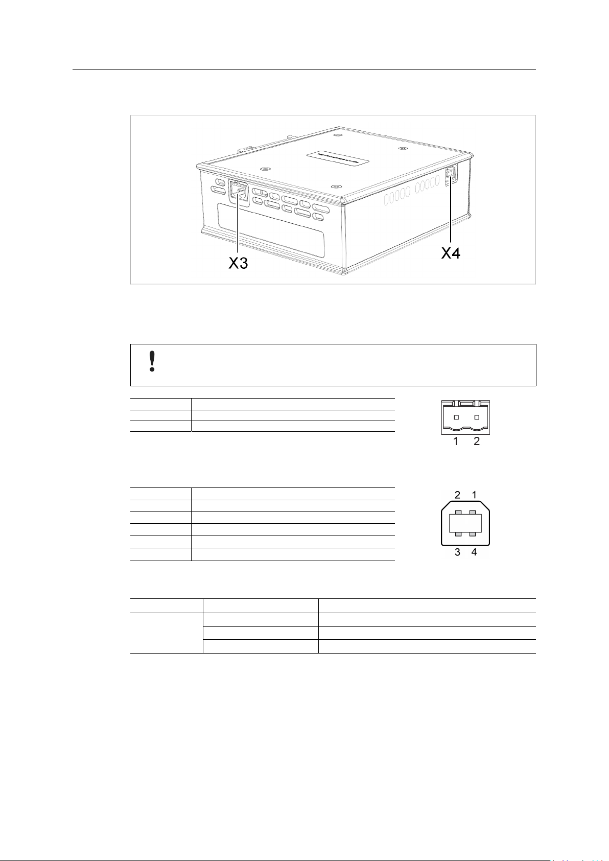
3.2 Connectors and Indicators
Fig. 7 Connectors
3.2.1 Power Connector (X3)
Connecting power with reverse polarity or using the wrong type of power supply may
damage the equipment. Make sure that the power supply is connected correctly and of
the recommended type.
Pin Signal
1 +24 VDC
2
Power Ground
3.2.2 USB Connector (X4)
Pin
1 +5 V input
2
3
4
Housing
Signal
USBDM (USB communication)
USBDP (USB communication)
Signal ground
Cable shield
3.2.3 LED Indicators
LED
GW Status Green Communication running
Other LED indicators, connectors and configuration switches are described in the documentation
for each respective network interface.
Indication Meaning
Red
Red, flashing Network interface error
Communication error
Anybus®X-gateway™User Manual
HMSI-27-262 4.0 en-US
Anybus Configuration Manager 13 (16)
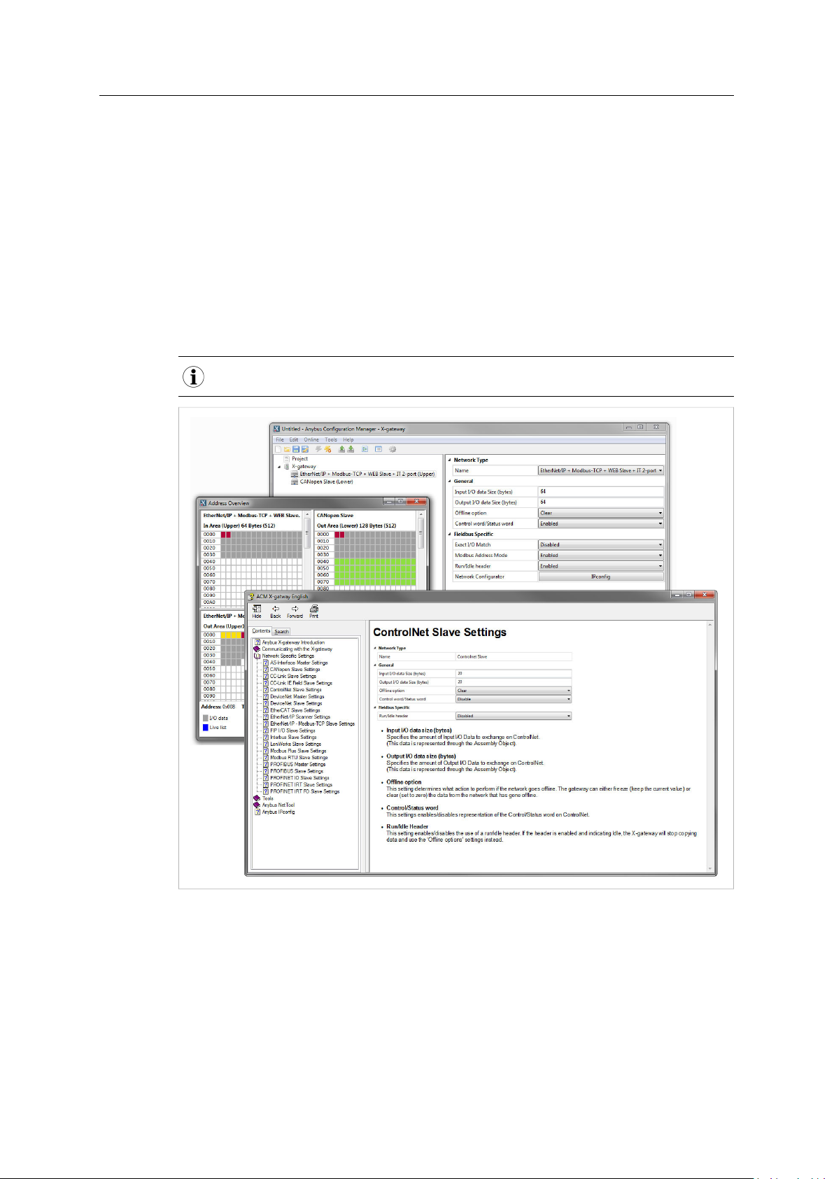
4 Anybus Configuration Manager
4.1 Introduction
The Anybus X-gateway usually requires only a minimum of configuration during setup, since the
on-board network interfaces are configured from the respective networks. Some parameters in
the gateway may however need to be adjusted to suit specific networks and applications.
The gateway settings are accessed via the USB port of the X-gateway using the Windows-based
application Anybus Configuration Manager.
This section describes only the general features and how to install Anybus Configuration Manager.
The network-specific settings are described in detail in the built-in help system and in the
documentation for each respective interface.
Anybus Configuration Manager requires Windows XP or later.
®
Anybus
X-gateway™User Manual
Fig. 8 Anybus Configuration Manager
HMSI-27-262 4.0 en-US

Anybus Configuration Manager 14 (16)
4.2 Setup
1. Download Anybus Configuration Manager and Anybus Transport Provider from
www.anybus.com/support.
2. Unzip the contents of each archive in a folder on your computer and double-click on the
setup executable, then follow the instructions in the installation wizard.
3. Connect a USB cable between the computer and the USB port on the X-gateway.
4. Start Anybus Configuration Manager and select Online > Select Connection.
Fig. 9 Select a connection
5. Select the connection to use for the X-gateway and click on OK. The USB connection will be
named Anybus Serial Connection.
There is normally no need to configure the connection unless you are connected to more
than one X-gateway. See the built-in help for more information.
6. Select Online > Connect to open the connection to the X-gateway.
4.3 Configuration
Once Anybus Configuration Manager has established a connection to the X-gateway,
configurations from the unit can be retrieved, viewed and modified.
1. Select Online > Upload Configuration to retrieve the configuration from the X-gateway.
2. The configuration can now be viewed and modified as required.
3. After making changes, select Online > Download Configuration to apply the modified
configuration to the X-gateway.
For more information about the various functions and settings, see the built-in help in Anybus
Configuration Manager and the documentation for each network interface.
Fig. 10 Anybus Configuration Manager help menu
®
Anybus
X-gateway™User Manual
HMSI-27-262 4.0 en-US
Appendix A: Technical Data 15 (16)
A Technical Data
Technical Specifications
Model name Anybus X-gateway
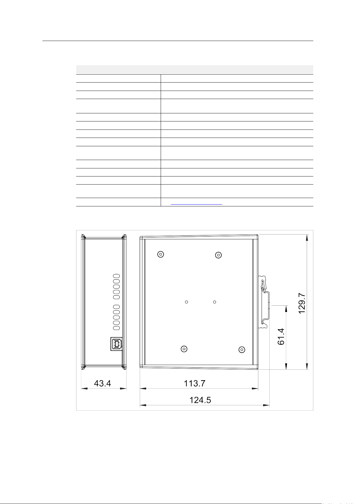
Dimensions (L x W x H)
Weight
Operating temperature
Storage temperature
Humidity range 5–95 % RH, non-condensing (IEC 60068-2-30)
Pressure range
Power supply 24 V ±20 % DC regulated power source
Current consumption
Configuration port USB (USB to CAN cable not included)
Galvanic isolation Yes, on both network sides
Mechanical rating
Mounting
Certifications
114 x 44 x 127 mm
400 g
-25 to +65 °C (IEC 60068-2-1 and IEC 60068-2-2)
(max. +50 °C for fibre optic interfaces)
-40 to +85 °C (IEC 60068-2-1 and IEC 60068-2-2)
85–105 kPa
Typical: 200 mA @ 24 VDC
Maximum: 400 mA @ 24 VDC
IP20, NEMA rating 1
DIN rail (EN 50022)
Network shield conductance via DIN rail
See www.anybus.com/support
All measurements are in millimeters.
®
Anybus
X-gateway™User Manual
Fig. 11 Anybus X-gateway dimensions
HMSI-27-262 4.0 en-US

last page
© 2019 HMS Industrial Networks
Box 4126
300 04 Halmstad, Sweden
info@hms.se HMSI-27-262 4.0 en-US / 2019-03-19 / 12401
 Loading...