

Page 1
Anybus X-gateway Gateway Installation Sheet
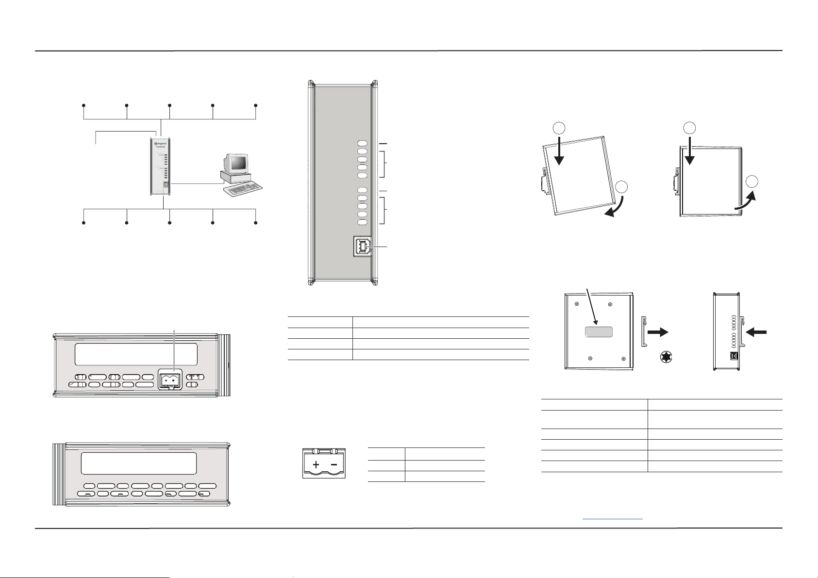
Concept
The Anybus X-gateway acts as a translation device between two
different fi eldbus networks.
Network 1
24 VDC
USB
Network 2
Internally the gateway consists of two separate network interfaces,
mounted at the top and bottom end of the gateway respectively, and a
translation device handling communication between the interfaces.
For more information about the specifi c interfaces, please refer to the
Network Installation Sheet for each fi eldbus network.
Top view
Power Connector (X3)
See Network Installation Sheet
for connector details
Front view
GW Status
GW Status
Top-mounted interface
Gateway Status LED
2–4 interface-specific LED Indicators
(see Network Installation Sheet)
Bottom-mounted interface
Gateway Status LED
2–4 interface-specific LED Indicators
(see Network Installation Sheet)
USB Connector (X4)
Gateway Status LED
Indication Meaning
Green Communication running
Red Communication error
Red (fl ashing) Network interface error
DIN Rail Mounting (standard)
Align the gateway with the DIN rail connector, then press fi rmly on the
top end and push the lower end into place.
To dismount the gateway, press fi rmly on the top end, then pull the
lower end away from the DIN rail.
1
Mount
1
2
Dismount
2
DIN Rail Mounting (sideways)
Remove the sticker covering the screw holes on the right side panel.
Unscrew the DIN clip from the back and refi t it to the side panel.
Mount/dismount the gateway the same way as in standard mounting.
Screw holes behind sticker
Remove for optional DIN retting
T10
Bottom view
See Network Installation Sheet
for connector details
The interface-specifi c LED indicators are described in the Network
Installation Sheets for the respective fi eldbus network interfaces.
Power Connector (X3)
Pin Signal
+ 24 VDC ±20 % Class 2
– Ground
Technical Specifi cations
Power supply 24 VDC ±20 % Class 2
Power consumption 200 mA at 24 VDC (typical)
400 mA at 24 VDC (maximum)
Operating temperature -25 to +65 °C @ 400 mA/24 VDC
Non-operating temperature -40 to +85 °C
Relative humidity 5–95 % non-condensing
Protective Earth (PE) Internal connection to PE via the DIN rail
Technical Support
Technical support, documentation and software downloads are
available at www.anybus.com.
www.anybus.comSP1747, rev. 2.10, Oct 2015
Page 2
Anybus X-gateway Gateway Installation Sheet
W
W
S
S
t
N
N
P
n
E
E
Additional Installation and Operating Instructions
Field wiring terminal markings (wire type (Cu only, 14-30 AWG))
Use 105 °C copper (Cu) wire only.
Terminal tightening torque: 5–7 lb-in (0.5–0.8 Nm)
Use in Overvoltage Category I Pollution Degree 2 Environment
conforming to EN 60664-1.
Operating temperature/Surrounding temperature:
-25 to +65 °C @ 300 mA @ 24 V DC
-25 to +50 °C @ 300 mA @ 24 V DC (Profi net IRT Fiber Optics)
Maximum surface temperature: 135 °C
Pressure: 850–1050 millibar (85–105 kPa)
This product is designed to safely operate in class I, division 2 Hazardous location according to ANSI/ISA 12.12.01-2013 and category 3,
zone 2 according to EN 60079-0:2012 and EN 60079-15:2010.
SUITABLE FOR USE IN CLASS I, DIVISION 2, GROUPS A, B, C
AND D HAZARDOUS LOCATIONS, OR NONHAZARDOUS
LOCATIONS ONLY.
To comply with ATEX directives, the equipment must be installed
within an IP54 enclosure and must be installed with a transient suppressor on the supply that does not exceed 140 % (33.6 V DC) of the
nominal rated supply voltage.
Warnings
• WARNING - EXPLOSION HAZARD - SUBSTITUTION OF ANY COMPONENTS MAY IMPAIR SUITABILITY FOR CLASS I, DIVISION 2.
• WARNING - EXPLOSION HAZARD - WHEN IN HAZARDOUS LOCATIONS, TURN OFF POWER BEFORE REPLACING OR WIRING
MODULES.
• WARNING - EXPLOSION HAZARD - DO NOT DISCONNECT
EQUIPMENT UNLESS POWER HAS BEEN SWITCHED OFF OR
THE AREA IS KNOWN TO BE NONHAZARDOUS.
• WARNING - EXPLOSION HAZARD- THE USB CONNECTOR IS NOT
FOR USE IN HAZARDOUS LOCATIONS AND FOR TEMPORARY
CONNECTION ONLY. DO NOT USE, CONNECT OR DISCONNECT
UNLESS THE AREA IS KNOWN TO BE NONHAZARDOUS. CONNECTION OR DISCONNECTION IN AN EXPLOSIVE ATMOSPHERE
COULD RESULT IN AN EXPLOSION.
• WARNING - INSTALL IN A TOOL LOCKED ENCLOSURE CONSIDERED REPRESENTATIVE OF THE INTENDED USE.
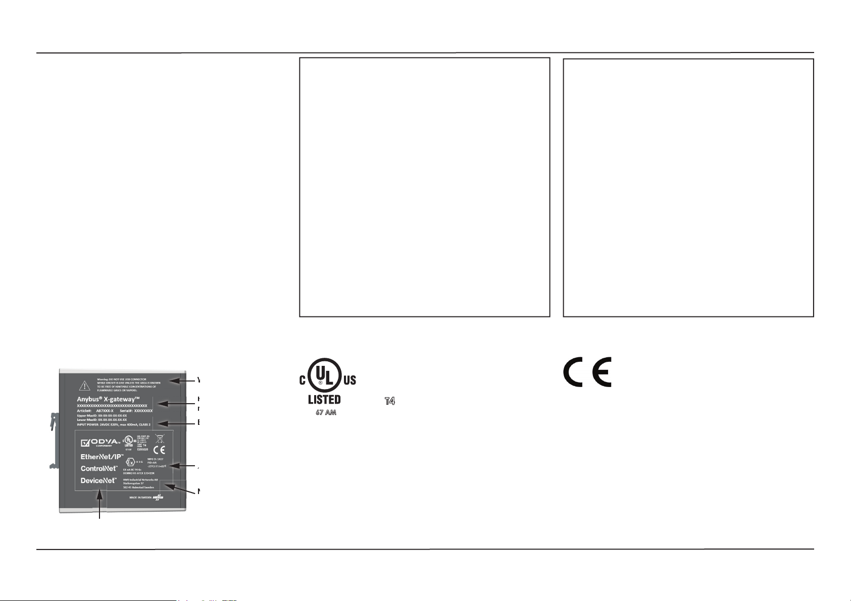
UL Certifi cationLabel Markings
Attention!
• ATTENTION – RISQUE D’EXPLOSION – LE REMPLACEMENT DE
TOUT COMPOSANTS INVALIDE LA CERTIFICATION CLASS I,
DIVISION 2.
• ATTENTION – RISQUE D’EXPLOSION – EN ZONE EXPLOSIVE,
VEUILLEZ COUPER L’ALIMENTATION ÉLECTRIQUE AVANT LE
REMPLACEMENT OU LE RACCORDEMENT DES MODULES.
• ATTENTION – RISQUE D’EXPLOSION – NE PAS DÉCONNECTER
L’ÉQUIPEMENT TANT QUE L’ALIMENTATION EST TOUJOURS
PRÉSENTE OU QUE LE PRODUIT EST TOUJOURS EN ZONE
EXPLOSIVE ACTIVE.
• ATTENTION – RISQUE D’EXPLOSION – LE CONNECTEUR USB
N’EST PAS FAIT POUR UN USAGE EN MILIEU EXPLOSIF. NE PAS,
BRANCHER ET DEBRANCHER SANS SAVOIR SI LA ZONE N’EST
PAS IDENTIFIEE NON EXPLOSIVE. BRANCHER OU DEBRANCHER EN ZONE EXPLOSIVE PEUT ENTRAINER UNE EXPLOSION.
• AVERTISSEMENT – INSTALLER DANS UNE ARMOIRE VERROUILLEE VALIDANT L’ACTE VOLONTAIRE D’UTILISATION.
EMC Compliance (CE)
IND: CONT. EQ.
Warnings
Product name,
number, description
Electrical rating
67 AM
ATEX Certifi cation
Surrounding
temperature rating
Name and address
of manufacturer
EX nA IIC T4 Gc
II 3 G
Y
Certification markings
Demko 03 ATEX 135419X
FOR HAZ LOC.
CL1, DIV 2
GP A,B,C,D
TEMP
T4
CODE
E203225
This product is in accordance with the EMC directive 2004/108/EC
through conformance with the following standards:
• EN 61000-6-4 (2007)
Emission standard for industrial environment
EN 55016-2-3, Class A (2010)
• EN 61000-6-2 (2005)
Immunity for industrial environment
EN 61000-4-2 (2009)
EN 61000-4-3 (2006)
EN 61000-4-4 (2012)
EN 61000-4-5 (2014)
EN 61000-4-6 (2014)
www.anybus.comSP1747, rev. 2.10, Oct 2015
 Loading...