

AAnnyybbuuss®®WWiirreelleessss BBrriiddggee IIII
STARTUP GUIDE
SCM-1202-013/SP2167 1.9 en-US ENGLISH
™™

Important User Information
Liability
Every care has been taken in the preparation of this document. Please inform HMS Industrial Networks
AB of any inaccuracies or omissions. The data and illustrations found in this document are not binding.
We, HMS Industrial Networks AB, reserve the right to modify our products in line with our policy of
continuous product development. The information in this document is subject to change without notice
and should not be considered as a commitment by HMS Industrial Networks AB. HMS Industrial
Networks AB assumes no responsibility for any errors that may appear in this document.
There are many applications of this product. Those responsible for the use of this device must ensure
that all the necessary steps have been taken to verify that the applications meet all performance and
safety requirements including any applicable laws, regulations, codes, and standards.
HMS Industrial Networks AB will under no circumstances assume liability or responsibility for any
problems that may arise as a result from the use of undocumented features, timing, or functional side
effects found outside the documented scope of this product. The effects caused by any direct or indirect
use of such aspects of the product are undefined, and may include e.g. compatibility issues and stability
issues.
The examples and illustrations in this document are included solely for illustrative purposes. Because of
the many variables and requirements associated with any particular implementation, HMS Industrial
Networks AB cannot assume responsibility for actual use based on these examples and illustrations.
Intellectual Property Rights
HMS Industrial Networks AB has intellectual property rights relating to technology embodied in the
product described in this document. These intellectual property rights may include patents and pending
patent applications in the USA and other countries.
®
Anybus
is a registered trademark and Wireless Bridge II™is a trademark of HMS Industrial Networks AB.
All other trademarks mentioned in this document are the property of their respective holders.
®
Anybus
Wireless Bridge II™Startup Guide
SCM-1202-013/SP2167 1.9 en-US
Preparation
1 Preparation
1.1 About This Document
This document describes how to install Anybus Wireless Bridge II and set up a
basic configuration.
For additional documentation, configuration examples, FAQs, troubleshooting
guides and technical support, please visit www.anybus.com/support.
1.2 Document Conventions
The following formatting conventions are used in this document to indicate
safety information and other content of specific importance:
WARNING
This instruction must be followed to avoid a risk of death or serious injury.
Caution
This instruction must be followed to avoid a risk of personal injury.
This instruction must be followed to avoid a risk of reduced functionality
and/or damage to the equipment, or to avoid a network security risk.
This is additional information which may facilitate installation and/or operation.
3 (16)
®
Anybus
Wireless Bridge II™Startup Guide
SCM-1202-013/SP2167 1.9 en-US

Preparation
1.3 Product Description
Anybus Wireless Bridge II provides wireless communication over WLAN and/or
®
Bluetooth
to wired networks.
Typical applications for Anybus Wireless Bridge II include:
• Adding wireless cloud connectivity to industrial devices
• Accessing devices from a laptop, smartphone or tablet
• Ethernet cable replacement between devices
Note:
Bluetooth PAN (Personal Area Network) may not work with some devices due
to different implementations of Bluetooth by different manufacturers.
WLAN 5 GHz cannot be used at the same time as WLAN 2.4 GHz or Bluetooth.
1.4 Model Name – Certification Identifier
The model name consists of a model prefix followed by two designators for
interface configuration and functionality.
Prefix
Interface configuration
Functionality
Example: AWB3AA = Anybus Wireless Bridge II with internal antenna, Ethernet
networking and digital input.
AWB3
Anybus Wireless Bridge II
A
Internal antenna, Dual M12
B
External antenna, Dual M12, RP-SMA
A
Ethernet with digital input
B
Ethernet w/o digital input
4 (16)
Anybus®Wireless Bridge II™Startup Guide
SCM-1202-013/SP2167 1.9 en-US
Installation 5 (16)
2 Installation
2.1 Safety
Caution
This equipment emits RF energy in the ISM (Industrial, Scientific, Medical)
band. Make sure that all medical devices used in proximity to this device
meet appropriate susceptibility specifications for this type of RF energy.
Caution
The M12 power and LAN connectors must be provided with tool
operated mechanical lock nuts that are tightened by the installer.
This product is recommended for use in both industrial and domestic
environments. For industrial environments it is mandatory to use the
functional earth connection to comply with immunity requirements. For
domestic environments the functional earth must be used if a shielded
Ethernet cable is used, in order to meet emission requirements.
This product contains parts that can be damaged by electrostatic
discharge (ESD). Use ESD prevention measures to avoid damage.
2.2 General Information
Make sure that you have all the necessary information about the capabilities
and restrictions of your local network environment before installation.
For optimal reception, wireless devices require a zone between them clear of
objects that could otherwise obstruct or reflect the signal. A minimum distance
of 50 cm between the devices should also be observed to avoid interference.
For models with internal antenna the characteristics of the antenna should be
considered when choosing the placement and orientation of the unit.
See the Anybus Wireless Bridge II User Manual for more information.
Anybus®Wireless Bridge II™Startup Guide
SCM-1202-013/SP2167 1.9 en-US
Installation 6 (16)
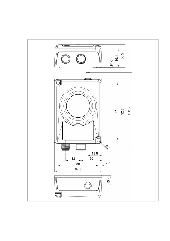
2.3 Mechanical Installation
Anybus Wireless Bridge II can be screw-mounted directly onto a flat surface or
mounted on a standard DIN rail using the optional DIN mounting kit.
All measurements are in mm.
Anybus®Wireless Bridge II™Startup Guide
SCM-1202-013/SP2167 1.9 en-US
Installation 7 (16)
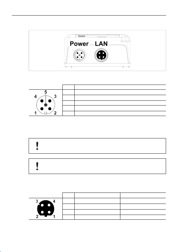
2.4 Connectors
Power Connector (A-coded male M12)
Pin Function
1
Power + (9–30 V)
2
Digital Input Ground
3
Power Ground
4
Digital Input + (9–30 V)
5
Functional Earth
The digital input can be used for additional functionality with advanced
configurations and to reset the unit. For more information please refer to the
Anybus Wireless Bolt/Bridge II AT Reference Guide.
If voltage is applied to the digital input for more that 10 seconds the unit
will be reset to factory defaults.
Signal wiring for the digital input must be carried in the same cable as
power and functional earth if wiring length exceeds 3 meters.
LAN Connector (D-coded female M12)
Pin Function
1 Transmit +
2 Receive +
3 Transmit - Orange
4 Receive - Green
Anybus®Wireless Bridge II™Startup Guide
Color coding (T568B)
Orange/White
Green/White
SCM-1202-013/SP2167 1.9 en-US
Installation 8 (16)
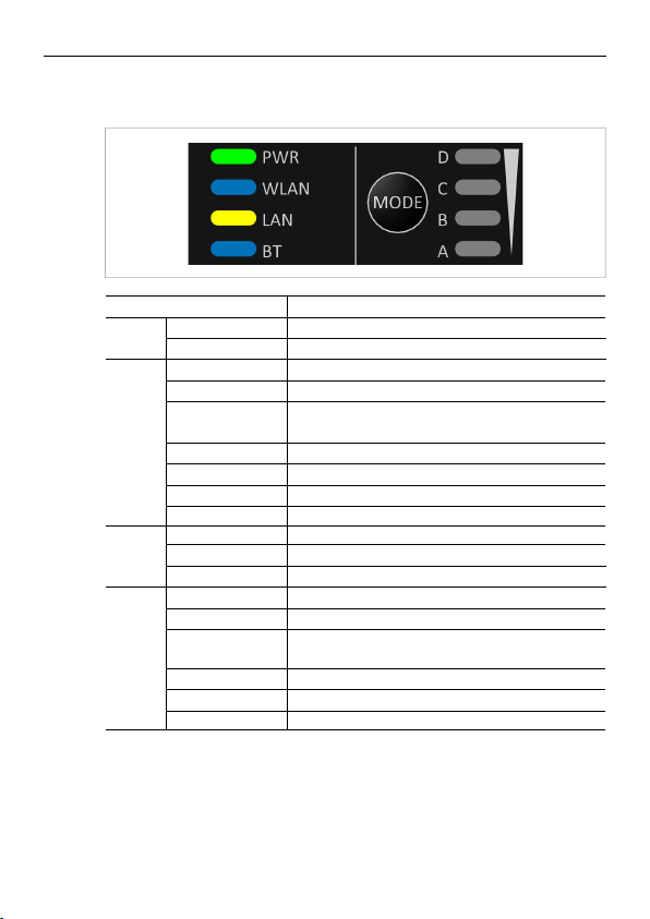
2.5 LED Indicators
Status Indicators
LED Indication
Off
PWR
Green
Off
Blue, blinking Access Point: No clients, awaiting connections
Blue
WLAN
Blue, flickering WLAN data activity (when connected)
Purple, blinking Client: Scanning for access points
Purple Client: Connecting to a detected access point
Red Unrecoverable error
Off No Ethernet connection
Yellow
LAN
Yellow, flickering Ethernet data activity (when connected)
Off
Blue, blinking NAP: No clients, awaiting connections
Blue
BT
Blue, flickering Bluetooth data activity (when connected)
Purple
Red Unrecoverable error
Anybus®Wireless Bridge II™Startup Guide
Description
No power
Normal operation
WLAN disabled or no power
Access Point: Connected to at least one client
Client: Connected to access point
Ethernet link present
Bluetooth disabled or no power
NAP: Connected to at least one PANU client
PANU: Connected to NAP
PANU: Trying to connect to NAP
SCM-1202-013/SP2167 1.9 en-US
Installation 9 (16)
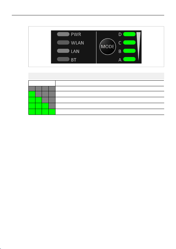
Link Quality/Mode Indicators
RSSI (WLAN Client) / Link Quality (Bluetooth PANU)
LED Description
A
A B
A B C
A B C D
No connection
RSSI/Link Quality < 25 %
RSSI/Link Quality 25–50 %
RSSI/Link Quality 50–75 %
RSSI/Link Quality > 75 %
These LEDs are also used when selecting an Easy Config mode and to indicate
update status in Recovery Mode.
See Easy Config, p. 11 and Recovery Mode LED Indications, p. 10.
Anybus®Wireless Bridge II™Startup Guide
SCM-1202-013/SP2167 1.9 en-US

Installation 10 (16)
2.6 MODE Button
The MODE button can be used to restart or reset the unit as well as for
selecting an Easy Config mode.
When the unit is powered on, press and hold MODE for >10 seconds and then
release it to reset to the factory default settings.
Recovery Mode
If the web interface cannot be accessed, the unit can be reset by starting in
Recovery Mode and reinstalling the firmware using Anybus Firmware Manager
II, which can be downloaded from www.anybus.com/support.
To enter Recovery Mode, press and hold RESET during startup.
Firmware updates should normally be carried out through the web
interface. Recovery Mode should only be used if the unit is unresponsive
and the web interface cannot be accessed.
Recovery Mode LED Indications
In Recovery Mode the Status LEDs will indicate firmware update status:
PWR
WLAN + BT
Green
Green, blinking Waiting for valid firmware
Alternating red/blue
Firmware update in progress
Firmware update in progress
Anybus®Wireless Bridge II™Startup Guide
SCM-1202-013/SP2167 1.9 en-US

Configuration 11 (16)
3 Configuration
Anybus Wireless Bridge II is normally configured via the web interface or using
one of the pre-configured Easy Config modes.
Advanced configuration can be carried out by issuing AT commands via the web
interface or over a Telnet or RAW TCP connection to port 8080.
3.1 Web Interface
The web interface is accessed by pointing a web browser to the IP address of
the unit. The default address is 192.168.0.99.
The configuration settings are described in detail in the User Manual.
3.2 Easy Config
1. Power on the unit and wait for the Link Quality LEDs to light up and go out
again, then immediately press and release the MODE button.
2. Press MODE repeatedly to cycle through the Easy Config modes until the
desired mode is indicated by the A-B-C-D LEDs.
3. Within 20 seconds of step 2, press and hold MODE for 2 seconds. When
the button is released the unit will restart in the selected mode.
Anybus®Wireless Bridge II™Startup Guide
SCM-1202-013/SP2167 1.9 en-US

Configuration 12 (16)
3.2.1 Easy Config Modes
EC LED
1 A Bluetooth PANU
2
A B
3
4
5 A C WLAN AP
6 B C Bluetooth NAP
7 A B C WLAN AP
8 D Bluetooth NAP
9 A D Bluetooth PANU
10 B D
11 A B D
The Easy Config modes are also described in detail when selected in the web
interface.
Role Description
B
–
–
C
Client
(any)
(any)
Configure as a client and scan for
another client (PANU to PANU).
Reset configuration to factory defaults.
Reset IP settings to factory defaults.
Wait for automatic configuration.
Configure units in mode 4 as clients.
Restart as access point and connect
clients.
Configure units in mode 4 as clients.
Restart as access point and connect
clients.
Apply PROFINET optimization to all units.
Configure as a client and scan for
another client (PANU to PANU).
Apply PROFINET optimization to both
units.
Apply PROFINET optimization and
restart.
Enable PROFIsafe mode.
Anybus®Wireless Bridge II™Startup Guide
SCM-1202-013/SP2167 1.9 en-US

Configuration 13 (16)
3.3 Factory Restore
Any one of these actions will restore the factory default settings:
• Clicking on Factory Restore on the System Settings page
• Executing Easy Config Mode 2
• Issuing the AT command AT&F and then restarting the unit
• Holding MODE pressed for >10 seconds and then releasing it
• Applying voltage to the digital input for >10 seconds
Default Network Settings
IP Assignment Static
IP Address
Subnet Mask
Default Gateway
Internal DHCP Server Disabled
Default WLAN Settings
Operating Mode Client
Channel Bands 2.4 GHz & 5 GHz
Authentication Mode
Channel
Bridge Mode Layer 3 IP forward
MIMO
Default Bluetooth Settings
Operating Mode PANU (Client)
Local Name [generated from MAC address]
Connectable
Discoverable
Security Mode Just works
Bluetooth LE Disabled
192.168.0.99
255.255.255.0
192.168.0.99
WPA/WPA2–PSK
Auto
AWB3000: Disabled
AWB3010: Enabled (Disabled before FW version
1.6.3)
No
No
Anybus®Wireless Bridge II™Startup Guide
SCM-1202-013/SP2167 1.9 en-US

Configuration 14 (16)
3.4 Configuration Examples
More examples can be found at www.anybus.com/support.
3.4.1 Ethernet Bridge via WLAN or Bluetooth
®
Configuration with Easy Config
This example describes how to connect two Ethernet network segments via
WLAN or Bluetooth using Easy Config.
Configuration
1. Power on the first unit and wait for the LEDs to light up and go out, then
press MODE and release it immediately.
2. Press MODE repeatedly until only LED C is lit (Easy Config Mode 4), then
confirm by pressing and holding MODE for 2 seconds.
This unit will now be discoverable and open for automatic configuration.
3. Power on the second unit and wait for the LEDs to light up and go out,
then press MODE and release it immediately..
4. Press MODE repeatedly on the second unit until A + C are lit (Mode 5) for
WLAN, or B + C (Mode 6) for Bluetooth, then confirm by pressing and
holding MODE for 2 seconds.
This unit should now automatically discover and configure unit 1 as a
WLAN or Bluetooth client, and configure itself as an access point.
Unit 1 will automatically be assigned the first free IP address within the
same Ethernet subnet as unit 2.
Adding More Devices
Up to 6 additional clients can be added by repeating the procedure. Each new
client will be assigned the next free IP address within the current subnet.
Anybus®Wireless Bridge II™Startup Guide
SCM-1202-013/SP2167 1.9 en-US

Technical Data 15 (16)
4 Technical Data
4.1 Hardware Specifications
Order code
Wired Interface type Ethernet
Antenna
Maximum range
Dimensions (LxWxH)
Weight
Operating temperature -40 to +65 °C
Storage temperature -40 to +85 °C
Humidity EN 600068-2-78: Damp heat, +40 °C, 93 % humidity for 4 days
Vibration See datasheet
Pressure 850 to 1050 mB
Housing material Plastic (see data sheet for details)
Protection class
Mounting Screw mount or DIN rail using optional clip
Power connector
Ethernet connector M12 female D-coded
Power supply 9–30 VDC (-5 % +20 %)
Power consumption
AWB3000 AWB3010
3 internal antennas:
2.4 GHz
2.4 GHz MIMO
5 GHz
400 m (WLAN and Bluetooth)
93 x 68 x 33.2 mm
120 g
IPX5
M12 male A-coded
Cranking 12 V (ISO 7637-2:2011 pulse 4)
Reverse polarity protection
0.7 W (idle), 1.7 W (max)
1 external antenna:
2.4 GHz + 5 GHz dual band
Anybus®Wireless Bridge II™Startup Guide
SCM-1202-013/SP2167 1.9 en-US

This page intentionally left blank

COMPLIANCE SHEET
This document does not include the complete instructions for the safe use of the described equipment. Make sure
that you have read and understood the safety instructions in the user documentation for the described equipment
before proceeding.
AAnnyybbuuss®®WWiirreelleessss BBrriiddggee IIII
™™
AAddddiittiioonnaall cceerrttiiffiiccaattiioonn aanndd ccoommpplliiaannccee iinnffoorrmmaattiioonn
EMC Compliance (CE)
This product is in compliance with the Radio Equipment Directive 2014/53/EU
through conformance with the following standards. The Declaration of Conformity
can be found at www.anybus.com/support.
Effective use of frequency
spectrum
EN 300 328 V2.1.1
EN 301 893 V2.1.1
EN 300 440 V2.1.1
EMC Safety
EN 61000-6-2:2005
EN 61000-6-3:2007 + A1:2011
EN 301 489-1 V2.1.1
EN 301 489-17 V3.1.1
EN 60950-1:2006 + A11:2009 +
A1:2010 + A12:2011 + A2:2013
EN 62311:2008 (Wi-Fi)
EN 62479:2010 (Bluetooth)
Disposal and recycling
You must dispose of this product properly according to local laws and regulations.
Because this product contains electronic components, it must be disposed of
separately from household waste. When this product reaches its end of life, contact
local authorities to learn about disposal and recycling options, or simply drop it off at
your local HMS office or return it to HMS. For more information, see
www.hms-networks.com.
© 2019 HMS Industrial Networks SP2145 1.2 en-US / 2018-10-08 / 9894

Anybus®Wireless Bridge II™Compliance Sheet 2 (3)
FCC Compliance Statement
This equipment complies with FCC radiation exposure limits set forth for an uncontrolled environment.
This equipment should be installed and operated with a minimum distance of 20 cm between the
radiator and your body.
This device complies with Part 15 of the FCC Rules. Operation is subject to the following two conditions:
1. this device may not cause harmful interference, and
2. this device must accept any interference received, including interference that may cause undesired
operation.
This product contains FCC ID: PVH0965
Any changes or modifications not explicitly approved by HMS Industrial
Networks AB could cause the module to cease to comply with FCC rules part
15, and thus void the user's authority to operate the equipment.
Industry Canada Statement
This equipment complies with IC RSS-102 radiation exposure limits set forth for an uncontrolled
environment. This equipment should be installed and operated with a minimum distance of 20 cm
between the radiator and your body.
Operation is subject to the following two conditions:
1. this device may not cause harmful interference, and
2. this device must accept any interference received, including interference that may cause undesired
operation of the device.
Cet équipement est conforme aux limites d'exposition de rayonnement d'IC RSS-102 déterminées pour
un environnement non contrôlé. Cet équipement devrait être installé et actionné avec la distance
minimum 20 cm entre le radiateur et votre corps.
Son utilisation est soumise aux deux conditions suivantes:
1. Cet appareil ne doit pas causer d’interférences et
2. il doit accepter toutes interférences reçues, y compris celles susceptibles d’avoir des effets
indésirables sur son fonctionnement.
This product contains IC ID: 5325A-0965
© 2019 HMS Industrial Networks SP2145 1.2 en-US / 2018-10-08 / 9894

Anybus®Wireless Bridge II™Compliance Sheet 3 (3)
Other Certifications
Contains MIC ID: R 204-510009 (indoor use only)
IFETEL
Marca: Anybus
Modelo: AWB3
NOM-208-SCF1-2016
La operación de este equipo está sujeta a las
siguientes dos condiciones:
(1) es posible que este equipo o dispositivo no cause
interferencia perjudicial y
(2) este equipo o dispositivo debe aceptar cualquier
interferencia, incluyendo la que pueda causar su
operación no deseada.
© 2019 HMS Industrial Networks SP2145 1.2 en-US / 2018-10-08 / 9894

This page intentionally left blank

COMPLIANCE SHEET
This document does not include the complete instructions for the safe use of the described equipment. Make sure
that you have read and understood the safety instructions in the user documentation for the described equipment
before proceeding.
AAnnyybbuuss®®WWiirreelleessss BBrriiddggee IIII
™™
AAddddiittiioonnaall cceerrttiiffiiccaattiioonn aanndd ccoommpplliiaannccee iinnffoorrmmaattiioonn
UL Ordinary Locations (Ord.Loc.)
Anybus Wireless Bridge II modules are certified for use in ordinary locations in compliance with the
following standards:
• UL 61010-1 SAFETY REQUIREMENTS FOR ELECTRICAL EQUIPMENT FOR MEASUREMENT, CONTROL,
AND LABORATORY USE - PART 1: GENERAL REQUIREMENTS - Edition 3 - Revision Date 2015/07/15
• UL 61010-2-201 STANDARD FOR SAFETY REQUIREMENTS FOR ELECTRICAL EQUIPMENT FOR
MEASUREMENT, CONTROL, AND LABORATORY USE - PART 2-201: PARTICULAR REQUIREMENTS FOR
CONTROL EQUIPMENT - Edition 1 - Issue Date 2014/01/24
• CSA C22.2 NO. 61010-1-12 SAFETY REQUIREMENTS FOR ELECTRICAL EQUIPMENT FOR
MEASUREMENT, CONTROL, AND LABORATORY USE. PT. 1, GENERAL REQUIREMENTS - Edition 3 Revision Date 2015/07/01
• CSA C22.2 NO. 61010-2-201:14 SAFETY REQUIREMENTS FOR ELECTRICAL EQUIPMENT FOR
MEASUREMENT, CONTROL, AND LABORATORY USE - PART 2-201: PARTICULAR REQUIREMENTS FOR
CONTROL EQUIPMENT - Edition 1 - Issue Date 2014/01/01
The certification number of Anybus Wireless Bridge II certified modules according to Ord.Loc.
certification is:
• E214107
According to the standards listed above, Anybus Wireless Bridge II modules are certified with the
following marking:
According to the standards listed above, the Anybus Wireless Bridge II modules shall be supplied by a
CLASS 2 / SELV classified power supply.

COMPLIANCE SHEET
This document does not include the complete instructions for the safe use of the described equipment. Make sure
that you have read and understood the safety instructions in the user documentation for the described equipment
before proceeding.
AAnnyybbuuss®®WWiirreelleessss BBrriiddggee IIII
™™
AAddddiittiioonnaall cceerrttiiffiiccaattiioonn aanndd ccoommpplliiaannccee iinnffoorrmmaattiioonn
UL Hazardous Locations (Haz.Loc.)
Anybus Wireless Bridge II modules are certified for use in hazardous locations in compliance with the
following standards:
• ANSI/ISA 12.12.01, 2015, Nonincendive Electrical Equipment for Use in Class I and II, Division 2 and
Class III, Divisions 1 and 2 Hazardous (Classified) Locations
• CAN/CSA C22.2 No. 213-15, 1st Ed., Non-incendive Electrical Equipment for Use in Class I, Division 2
Hazardous Locations
The certification number of the Anybus Wireless Bridge II certified modules according to Haz.Loc
certification is:
• E203225
According to the standards listed above, Anybus Wireless Bridge II modules are certified with the
following marking:
Note: The UL marking for Ord.Loc. and Haz.Loc. are merged into one, where only the certification
number for Haz.Loc are required.
The above marking indicates that Anybus Wireless Bridge II modules are certified as electrical equipment
to be used in the following hazardous locations:
• Class I, Division 2 - An area where ignitable concentrations of flammable gases, vapors or liquids are
NOT likely to exist under normal operating conditions.
• Group A: Acetylene
• Group B: Flammable gas, flammable liquid-produced vapor or combustible liquid-produced vapor
mixed with air that may burn or explode, having either a maximum experimental safe gap (MESG)
value less than or equal to 0.45mm or minimum igniting current ratio (MIC ratio) less than or equal
to 0.40. Example: Hydrogen

Anybus®Wireless Bridge II™Compliance Sheet 2 (3)
• Group C: Flammable gas, flammable liquid-produced vapor or combustible liquid-produced vapor
mixed with air that may burn or explode, having either a maximum experimental safe gap (MESG)
value greater than or equal to 0.45mm or less than 0.75mm, or minimum igniting current ratio (MIC
ratio) greater than 0.40 and less than or equal to 0.80. Example: Ethylene
• Group D: Flammable gas, flammable liquid-produced vapor or combustible liquid-produced vapor
mixed with air that may burn or explode, having either a maximum experimental safe gap (MESG)
value greater than or equal to 0.75mm or minimum igniting current ratio (MIC ratio) greater than
0.80. Example: Propane
Warnings
• WARNING: EXPLOSION HAZARD - SUBSTITUTION OF ANY COMPONENTS MAY IMPAIR SUITABILITY
FOR THE EXPLOSIVE ENVIRONMENT.
• WARNING: EXPLOSION HAZARD - WHEN IN HAZARDOUS LOCATIONS, TURN OFF POWER BEFORE
REPLACING OR WIRING MODULES.
• WARNING: EXPLOSION HAZARD - DO NOT DISCONNECT EQUIPMENT WHILE THE CIRCUIT IS LIVE OR
UNLESS THE AREA IS KNOWN TO BE FREE OF IGNITABLE CONCENTRATIONS.
• WARNING: EXPLOSION HAZARD - DO NOT CONNECT OR DISCONNECT THE ANTENNA UNLESS THE
AREA IS KNOWN TO BE NONHAZARDOUS. CONNECTION OR DISCONNECTION IN AN EXPLOSIVE
ATMOSPHERE COULD RESULT IN AN EXPLOSION.
• WARNING: EXPLOSION HAZARD - EXTERNAL TERMINALS MUST BE SECURED MECHANICALLY WITH A
TOOL TO PREVENT UNINTENTIONAL SEPARATION. UNINTENTIONAL SEPARATION WHILE IN
ENERGIZED STATE COULD RESULT IN AN EXPLOSION.
• WARNING: EXPLOSION HAZARD - IF THE EQUIPMENT IS TO BE USED OUTSIDE, INSTALL WITHIN AN
ENCLOSURE CONSIDERED REPRESENTATIVE OF THE INTENDED USE. TO COMPLY WITH HAZLOC
STANDARDS, THE EQUIPMENT MUST BE INSTALLED WITHIN AN IP54 ENCLOSURE.
• WARNING: EXPLOSION HAZARD - IF THE EQUIPMENT IS TO BE USED WITH AN EXTERNAL ANTENNA,
INSTALL THE EQUIPMENT WITHIN AN ENCLOSURE CONSIDERED REPRESENTATIVE OF THE INTENDED
USE. TO COMPLY WITH HAZLOC STANDARDS, THE EQUIPMENT MUST BE INSTALLED WITHIN AN IP54
ENCLOSURE.
Avertissements
• AVERTISSEMENT : RISQUE D'EXPLOSION - LA SUBSTITUTION DE TOUT COMPOSANT PEUT
COMPROMETTRE LA CONVENANCE À L’ENVIRONNEMENT EXPLOSIF.
• AVERTISSEMENT : RISQUE D'EXPLOSION - LORSQUE VOUS ÊTES SITUÉ DANS UN ENDROIT
DANGEREUX, METTEZ L’APPAREIL HORS TENSION AVANT DE REMPLACER OU DE CÂBLER DES
MODULES.
• AVERTISSEMENT : RISQUE D’EXPLOSION - NE PAS DÉBRANCHER L’ÉQUIPEMENT LORSQUE LE
CIRCUIT EST SOUS TENSION NI SANS ÊTRE SÛR QUE LA ZONE EST EXEMPTE CONCENTRATIONS
INFLAMMABLES.
• AVERTISSEMENT : RISQUE D'EXPLOSION - NE PAS BRANCHER OU DÉBRANCHER L’ANTENNE, SAUF SI
LA ZONE EST CERTIFIÉE NON DANGEREUSE. LA CONNEXION OU LA DÉCONNEXION DANS UNE
ATMOSPHÈRE EXPLOSIVE PEUT ENTRAÎNER UNE EXPLOSION.

Anybus®Wireless Bridge II™Compliance Sheet 3 (3)
• AVERTISSEMENT : RISQUE D'EXPLOSION - LA BORNE EXTERNE DOIT ÊTRE FIXÉE MÉCANIQUEMENT À
L’AIDE D’UN OUTIL POUR ÉVITER TOUTE SÉPARATION INVOLONTAIRE. UNE SÉPARATION
INVOLONTAIRE ALORS QUE L’APPAREIL EST SOUS TENSION PEUT ENTRAÎNER UNE EXPLOSION.
• AVERTISSEMENT : RISQUE D'EXPLOSION - SI L’ÉQUIPEMENT EST UTILISÉ À L’EXTÉRIEUR, INSTALLER
DANS UN BOÎTIER JUGÉ REPRÉSENTATIF DE L’UTILISATION PRÉVUE. POUR ÊTRE CONFORME AUX
NORMES HAZLOC, L’ÉQUIPEMENT DOIT ÊTRE INSTALLÉ DANS UN BOÎTIER IP54.
• AVERTISSEMENT : RISQUE D'EXPLOSION - SI L’ÉQUIPEMENT EST UTILISÉ UNE ANTENNE EXTERNE,
INSTALLER DANS UN BOÎTIER JUGÉ REPRÉSENTATIF DE L’UTILISATION PRÉVUE. POUR ÊTRE
CONFORME AUX NORMES HAZLOC, L’ÉQUIPEMENT DOIT ÊTRE INSTALLÉ DANS UN BOÎTIER IP54.

COMPLIANCE SHEET
This document does not include the complete instructions for the safe use of the described equipment. Make sure
that you have read and understood the safety instructions in the user documentation for the described equipment
before proceeding.
AAnnyybbuuss®®WWiirreelleessss BBrriiddggee IIII
™™
AAddddiittiioonnaall cceerrttiiffiiccaattiioonn aanndd ccoommpplliiaannccee iinnffoorrmmaattiioonn
ATEX
Anybus Wireless Bridge II modules are certified for use in potentially explosive atmospheres in
compliance with the following standards:
• EN 60079-0: 2012 + A11:2013
• EN 60079-15: 2010
The certification number of the Anybus Wireless Bridge II certified modules according to the ATEX
directive 2014/34/EU is:
• DEMKO-17ATEX1895X
According to the two standards listed above, the Anybus Wireless Bridge II modules are certified with the
following marking:
The above marking indicates that Anybus Wireless Bridge II modules are certified as electrical equipment
of:
• equipment group “II” : intended for use in areas with explosive gas atmosphere other than mines
susceptible to firedamp.
• category “3 G”: intended for use in zone 2 hazardous areas, in which explosive atmospheres caused
by mixtures of air and gases, vapors or mists are present between 1 and 10 hrs/yr.
• level of protection “nA”: non-sparking (for Equipment Protection Level Gc)
• subdivision ‘IIC’: intended for use in areas where the nature of the explosive gas atmosphere is
considered very dangerous based on the Maximum Experimental Safe Gap or the Minimum Ignition
Current ratio of the explosive gas atmosphere in which the equipment may be installed (a typical
gas is hydrogen), so that the modules are also suitable for applications intended for use in
subdivision IIB (typical gas is ethylene) and subdivision IIA (a typical gas is propane). Gas group IIC is
the most stringent group and covers also groups IIB and IIA.
• temperature class “T4”: The maximum surface temperature determined shall not exceed 135 °C

Anybus®Wireless Bridge II™Compliance Sheet 2 (2)
• equipment protection level “Gc”: equipment for explosive gas atmospheres, having an “enhanced”
level of protection, which is not a source of ignition in normal operation and which may have some
additional protection to ensure that it remains inactive as an ignition source in the case of regular
expected occurrences (for example failure of a lamp)
Special Conditions of Use:
• The equipment shall only be used in an area of at least pollution degree 2, as defined in IEC 60664-1.
• The equipment shall be installed in an enclosure that provides a minimum ingress protection of IP
54 in accordance with EN 60079-15.
• Transient protection shall be provided that is set at a level not exceeding 140 % of the peak rated
voltage value at the supply terminals to the equipment.
Warnings
• WARNING - EXPLOSION HAZARD - SUBSTITUTION OF ANY COMPONENTS MAY IMPAIR SUITABILITY
FOR THE EXPLOSIVE ENVIRONMENT.
• WARNING - EXPLOSION HAZARD - WHEN IN HAZARDOUS LOCATIONS, TURN OFF POWER BEFORE
REPLACING OR WIRING MODULES.
• WARNING - EXPLOSION HAZARD - DO NOT DISCONNECT EQUIPMENT WHILE THE CIRCUIT IS LIVE OR
UNLESS THE AREA IS KNOWN TO BE FREE OF IGNITABLE CONCENTRATIONS.
• WARNING - EXPLOSION HAZARD - DO NOT CONNECT OR DISCONNECT THE ANTENNA UNLESS THE
AREA IS KNOWN TO BE NONHAZARDOUS. CONNECTION OR DISCONNECTION IN AN EXPLOSIVE
ATMOSPHERE COULD RESULT IN AN EXPLOSION.
• WARNING - EXPLOSION HAZARD - EXTERNAL TERMINALS MUST BE SECURED MECHANICALLY WITH
A TOOL TO PREVENT UNINTENTIONAL SEPARATION. UNINTENTIONAL SEPARATION WHILE IN
ENERGIZED STATE COULD RESULT IN AN EXPLOSION.
• WARNING - EXPLOSION HAZARD - IF THE EQUIPMENT IS TO BE USED OUTSIDE, INSTALL WITHIN AN
ENCLOSURE CONSIDERED REPRESENTATIVE OF THE INTENDED USE. TO COMPLY WITH ATEX
DIRECTIVES, THE EQUIPMENT MUST BE INSTALLED WITHIN AN IP54 ENCLOSURE.

This page intentionally left blank

last page
© 2019 HMS Industrial Networks
Box 4126
300 04 Halmstad, Sweden
info@hms.se
SCM-1202-013/SP2167 1.9 en-US / 2018-09-05 / 9496
 Loading...