

Page 1
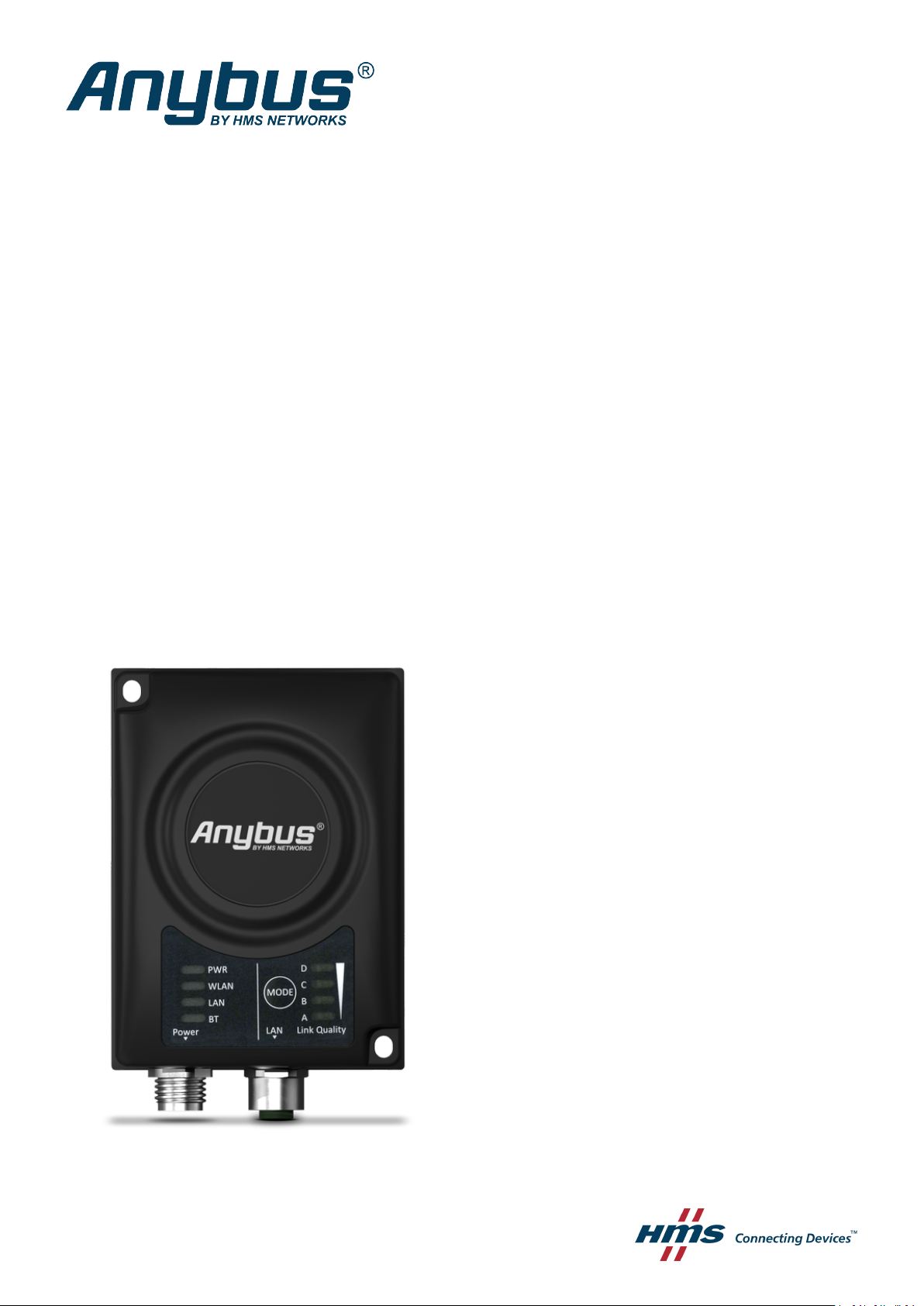
Anybus®Wireless Bridge II
USER MANUAL
SCM-1202-032 2.4 en-US ENGLISH
™
Page 2

Important User Information
Disclaimer
The information in this document is for informational purposes only. Please inform HMS Networks of any
inaccuracies or omissions found in this document. HMS Networks disclaims any responsibility or liability for any
errors that may appear in this document.
HMS Networks reserves the right to modify its products in line with its policy of continuous product development.
The information in this document shall therefore not be construed as a commitment on the part of HMS Networks
and is subject to change without notice. HMS Networks makes no commitment to update or keep current the
information in this document.
The data, examples and illustrations found in this document are included for illustrative purposes and are only
intended to help improve understanding of the functionality and handling of the product. In view of the wide range
of possible applications of the product, and because of the many variables and requirements associated with any
particular implementation, HMS Networks cannot assume responsibility or liability for actual use based on the data,
examples or illustrations included in this document nor for any damages incurred during installation of the product.
Those responsible for the use of the product must acquire sufficient knowledge in order to ensure that the product
is used correctly in their specific application and that the application meets all performance and safety requirements
including any applicable laws, regulations, codes and standards. Further, HMS Networks will under no circumstances
assume liability or responsibility for any problems that may arise as a result from the use of undocumented features
or functional side effects found outside the documented scope of the product. The effects caused by any direct or
indirect use of such aspects of the product are undefined and may include e.g. compatibility issues and stability
issues.
Anybus®Wireless Bridge II™User Manual
SCM-1202-032 2.4 en-US
Page 3

Table of Contents
Page
1 Preface ................................................................................................................................. 3
1.1 About This Document ............. ....................... ................................ ................................ ... 3
1.2 Document Conventions ....................... ................................ ................................ .............. 3
1.3 Trademarks.......... ................................ ................................ ....................... ......... ...........3
2 Safety ................................................................................................................................... 4
2.1 General Safety Instructions . ......... ....................... ................................ ................ ............... 4
2.2 External Antenna Restrictions.................. ................................ ................................ ...........4
2.3 Intended Use.. ................ ................ ................ ....................... ......... ....................... ......... . 4
2.4 Type Identification ........... ....................................... ................................ .........................4
3 Installation........................................................................................................................... 5
3.1 General Information ........................... ....................................................................... ....... 5
3.2 Limitations........ ....................................................................... ................................ ....... 5
3.3 Mechanical Installation ...... ......... ....................... ................................ ................ ............... 6
3.4 Connectors ...... ....................... ......... ....................... ................ ................ ................ ........ 7
3.5 LED Indicators ....................... ....................... ......... ....................... ................................ ... 8
3.6 MODE Button ....... ....................................................................... ................ ................ .. 10
4 Configuration..................................................................................................................... 11
4.1 General ............................. ....................... ................................ ................ ................ .... 11
4.2 Easy Config ...................... ......... ....................... ......... ....................... ................ ............. 11
4.3 Web Interface .................. ................ ................ ................ ................................ ............. 12
4.4 Factory Restore ................ ................ ................ ................ ....................... ......... ............. 28
A Configuration Examples .................................................................................................... 29
A.1 Ethernet Bridge via WLAN or Bluetooth®(Easy Config) .... ................ ................................ ...... 29
®
A.2 PROFINET networking via Bluetooth
A.3 EtherNet/IP
A.4 Ethernet network to existing WLAN............................ ....................................... ................ 32
A.5 Adding single Ethernet node to WLAN .. ................ ................ ................................ ............. 34
A.6 Accessing PLC via WLAN from Handheld Device ....................... ....................................... ..... 35
™
Networking via Bluetooth®............................. ................................ ................ 31
............. ................ ................................ .................... 30
B Technical Data ................................................................................................................... 37
B.1 Hardware Specifications ........... ....................................... ................................ ................ 37
B.2 Communication ........... ................................ ....................... ......... ....................... ......... .. 38
B.3 Internal Antenna Characteristics ..................... ................................ ....................... ......... .. 39
C Wireless Technology Basics .............................................................................................. 44
Anybus®Wireless Bridge II™User Manual
SCM-1202-032 2.4 en-US
Page 4

This page intentionally left blank
Page 5
Preface 3 (46)
1 Preface
1.1 About This Document
This document describes how to install and configure Anybus Wireless Bridge II.
For additional documentation and software downloads, FAQs, troubleshooting guides and
technical support, please visit www.anybus.com/support.
1.2 Document Conventions
Numbered lists indicate tasks that should be carried out in sequence:
1. First do this
2. Then do this
Bulleted lists are used for:
• Tasks that can be carried out in any order
• Itemized information
► An action
→ and a result
User interaction elements (buttons etc.) are indicated with bold text.
Program code and script examples
Cross-reference within this document: Document Conventions, p. 3
External link (URL): www.hms-networks.com
WARNING
Instruction that must be followed to avoid a risk of death or serious injury.
Caution
Instruction that must be followed to avoid a risk of personal injury.
Instruction that must be followed to avoid a risk of reduced functionality and/or damage
to the equipment, or to avoid a network security risk.
Additional information which may facilitate installation and/or operation.
1.3 Trademarks
Anybus®is a registered trademark and Wireless Bridge II™is a trademark of HMS Industrial
Networks AB. All other trademarks mentioned in this document are the property of their
respective holders.
Anybus®Wireless Bridge II™User Manual
SCM-1202-032 2.4 en-US
Page 6
Safety 4 (46)
2 Safety
2.1 General Safety Instructions
Caution
This equipment emits RF energy in the ISM (Industrial, Scientific, Medical) band. Make
sure that all medical devices used in proximity to this equipment meet appropriate
susceptibility specifications for this type of RF energy.
This equipment is recommended for use in both industrial and domestic environments.
For industrial environments it is mandatory to use the functional earth connection to
comply with immunity requirements. For domestic environments the functional earth
must be used if a shielded Ethernet cable is used, in order to meet emission requirements.
This equipment contains parts that can be damaged by electrostatic discharge (ESD). Use
ESD prevention measures to avoid damage.
2.2 External Antenna Restrictions
For models with external antenna, only use antennas that are certified for use with this
equipment. Using external antennas that are not certified for use with this equipment will
invalidate its certifications and make it non-compliant with the regulations for radio equipment.
A list of certified antennas can be found at www.anybus.com/support.
2.3 Intended Use
The intended use of this equipment is as a communication interface and gateway. The
equipment receives and transmits data on various physical levels and connection types.
If this equipment is used in a manner not specified by the manufacturer, the protection provided
by the equipment may be impaired.
2.4 Type Identification
The type name consists of a type prefix followed by two designators for interface configuration
and functionality.
Prefix
Interface configuration
Functionality
AWB3
A
B
A
B
Anybus Wireless Bridge II
Internal antenna, Dual M12
External antenna, Dual M12, RP-SMA
Ethernet with digital input
Ethernet w/o digital input
Example: AWB3AA = Anybus Wireless Bridge II with internal antenna, Ethernet networking and
digital input.
Anybus®Wireless Bridge II™User Manual
SCM-1202-032 2.4 en-US
Page 7

Installation 5 (46)
3 Installation
3.1 General Information
Make sure that you have all the necessary information about the capabilities and restrictions of
your local network environment before installation.
For models with internal antenna the characteristics of the antenna should be considered when
choosing the placement and orientation of the unit.
For optimal reception, wireless devices require a zone between them clear of objects that could
otherwise obstruct or reflect the signal. A minimum distance of 50 cm between the devices
should also be observed to avoid interference.
See also Wireless Technology Basics, p. 44.
3.2 Limitations
Bluetooth PAN (Personal Area Network) may not work with some devices due to different
implementations of Bluetooth by different manufacturers.
WLAN 5 GHz cannot be used at the same time as WLAN 2.4 GHz or Bluetooth.
Anybus®Wireless Bridge II™User Manual
SCM-1202-032 2.4 en-US
Page 8
Installation 6 (46)
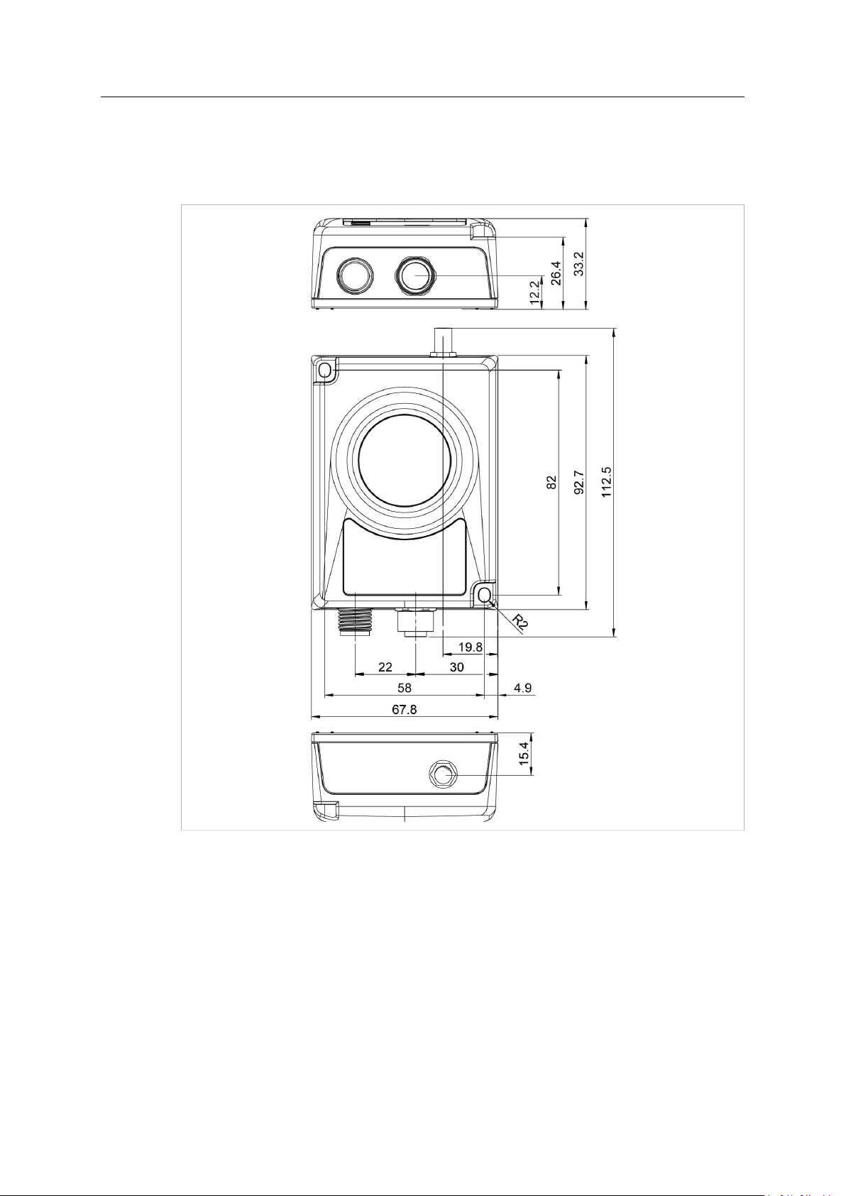
3.3 Mechanical Installation
Anybus Wireless Bridge II can be screw-mounted directly onto a flat surface or mounted on a
standard DIN rail using the optional DIN mounting kit.
Fig. 1 Installation drawing
All measurements are in mm.
Anybus®Wireless Bridge II™User Manual
SCM-1202-032 2.4 en-US
Page 9
Installation 7 (46)
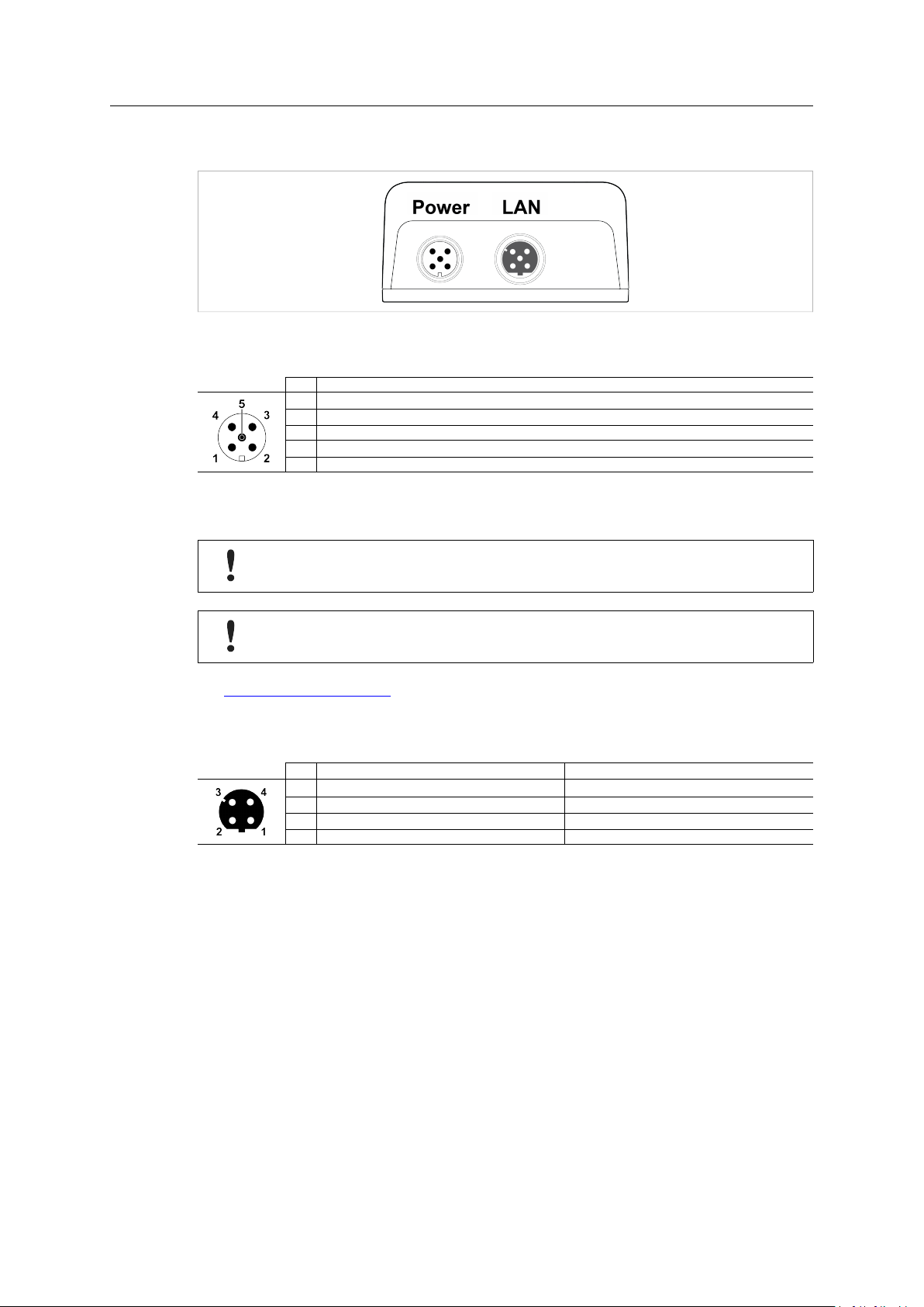
3.4 Connectors
Fig. 2 M12 connectors
Power Connector (A-coded male M12)
Pin Function
1
Power + (9–30 V)
2
Digital Input Ground
3
Power Ground
4
Digital Input + (9–30 V)
5
Functional Earth
The digital input can be used for additional functionality with advanced configurations and to
remotely reset the unit.
If voltage is applied to the digital input for more that 10 seconds the unit will be reset to
factory defaults.
Signal wiring for the digital input must be carried in the same cable as power and
functional earth if wiring length exceeds 3 meters.
See www.anybus.com/support for more information about the digital input.
LAN Connector (D-coded female M12)
Pin Function
1 Transmit +
2 Receive +
3 Transmit - Orange
4 Receive - Green
Color coding (T568B)
Orange/White
Green/White
®
Anybus
Wireless Bridge II™User Manual
SCM-1202-032 2.4 en-US
Page 10

Installation 8 (46)
3.5 LED Indicators
3.5.1 Status Indicators
Fig. 3 Status LED indicators
LED Indication
PWR
WLAN
LAN
BT
Off
Green
Off
Blue, blinking Access Point: No clients, awaiting connections
Blue
Blue, flickering WLAN data activity (when connected)
Purple, blinking Client: Scanning for access points
Purple Client: Connecting to a detected access point
Red Unrecoverable error
Off No Ethernet connection
Yellow
Yellow, flickering Ethernet data activity (when connected)
Off
Blue, blinking NAP: No clients, awaiting connections
Blue
Blue, flickering Bluetooth data activity (when connected)
Purple
Red Unrecoverable error
Description
No power
Normal operation
WLAN disabled or no power
Access Point: Connected to at least one client
Client: Connected to access point
Ethernet link present
Bluetooth disabled or no power
NAP: Connected to at least one PANU client
PANU: Connected to NAP
PANU: Trying to connect to NAP
®
Anybus
Wireless Bridge II™User Manual
SCM-1202-032 2.4 en-US
Page 11
Installation 9 (46)
3.5.2 Link Quality/Mode Indicators
Fig. 4 Link Quality/Mode indicators
RSSI (WLAN Client) / Link Quality (Bluetooth PANU)
LED
A
A B
A B C
A B C D
These LEDs are also used when selecting an Easy Config mode and to indicate update status in
Recovery Mode.
Description
No connection
RSSI/Link Quality < 25 %
RSSI/Link Quality 25–50 %
RSSI/Link Quality 50–75 %
RSSI/Link Quality > 75 %
See Easy Config, p. 11 and Recovery Mode LED Indications, p. 10.
Anybus®Wireless Bridge II™User Manual
SCM-1202-032 2.4 en-US
Page 12
Installation 10 (46)
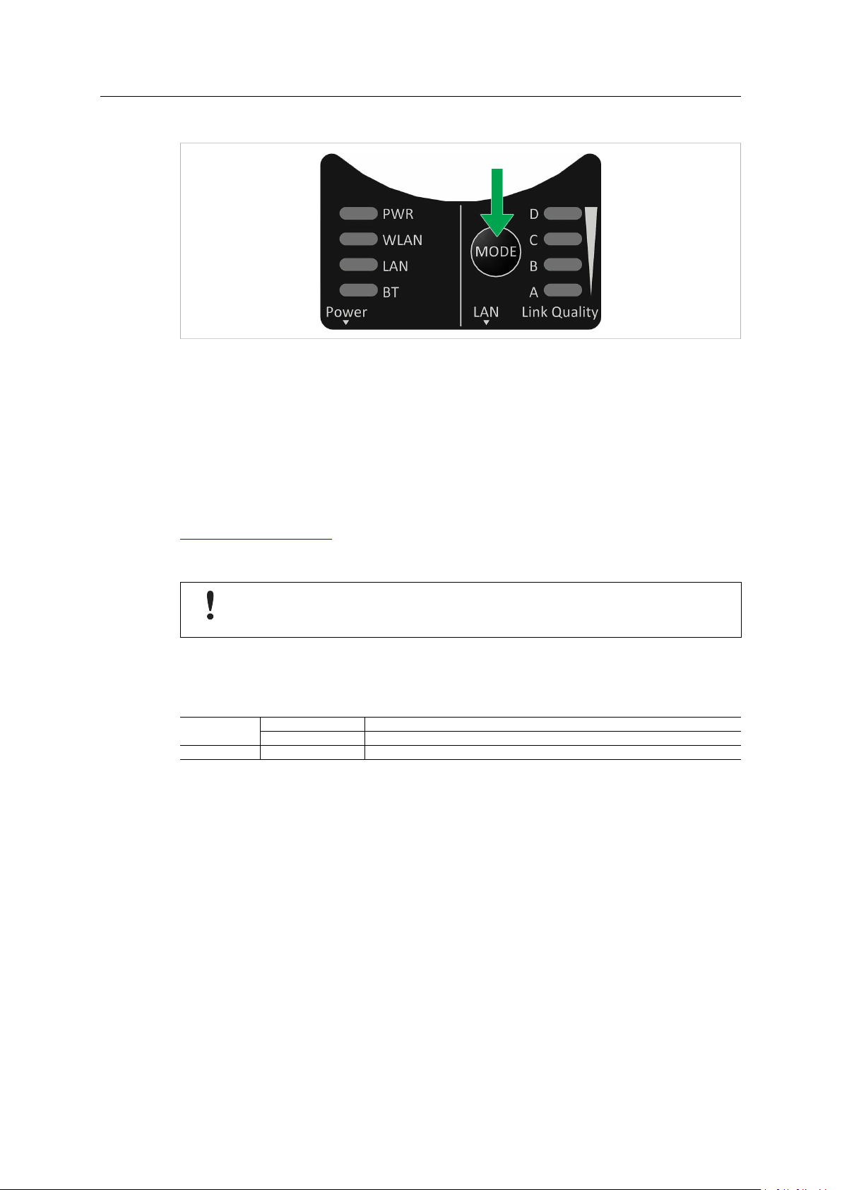
3.6 MODE Button
Fig. 5 MODE button
The MODE button can be used to restart or reset the unit as well as for selecting an Easy Config
mode.
When the unit is powered on, press and hold MODE for >10 seconds and then release it to reset
to the factory default settings.
Recovery Mode
If the web interface cannot be accessed, the unit can be reset by starting in Recovery Mode and
reinstalling the firmware using Anybus Firmware Manager II, which can be downloaded from
www.anybus.com/support.
To enter Recovery Mode, press and hold RESET during startup.
Firmware updates should normally be carried out through the web interface. Recovery
Mode should only be used if the unit is unresponsive and the web interface cannot be
accessed.
Recovery Mode LED Indications
In Recovery Mode the Status LEDs will indicate firmware update status:
PWR
WLAN + BT
Green
Green, blinking Waiting for valid firmware
Alternating red/blue
Firmware update in progress
Firmware update in progress
®
Anybus
Wireless Bridge II™User Manual
SCM-1202-032 2.4 en-US
Page 13

Configuration 11 (46)
4 Configuration
4.1 General
Anybus Wireless Bridge II can be configured via the web interface or using one of the preconfigured Easy Config modes.
Advanced configuration can be carried out by issuing AT (modem) commands through the web
interface or over a Telnet or RAW TCP connection to port 8080. For more information about
using AT commands, please refer to the AT Commands Reference Guide.
4.2 Easy Config
1. Power on the unit and wait for the Link Quality LEDs to light up and go out again, then
immediately press and release the MODE button.
2. Press MODE repeatedly to cycle through the Easy Config modes until the desired mode is
indicated by the A-B-C-D LEDs.
3. Within 20 seconds of step 2, press and hold MODE for 2 seconds. When the button is
released the unit will restart in the selected mode.
4.2.1 Easy Config Modes
EC LED
1 A
2
3
4
5 A C WLAN AP
6 B C
7 A B C WLAN AP
8 D
9 A D
10 B D
11 A B D
The Easy Config modes are also described when selected in the web interface.
B
A B
C
Role Description
Bluetooth PANU
–
–
Client
Bluetooth NAP
Bluetooth NAP
Bluetooth PANU
(any) Apply PROFINET optimization and restart.
(any)
Configure as a client and scan for another client (PANU to PANU).
Reset configuration to factory defaults.
Reset IP settings to factory defaults.
Wait for automatic configuration.
Configure units in mode 4 as clients.
Restart as access point and connect clients.
Configure units in mode 4 as clients.
Restart as access point and connect clients.
Apply PROFINET optimization to all units.
Configure as a client and scan for another client (PANU to PANU).
Apply PROFINET optimization to both units.
Enable PROFIsafe mode.
Anybus®Wireless Bridge II™User Manual
SCM-1202-032 2.4 en-US
Page 14
Configuration 12 (46)
4.3 Web Interface
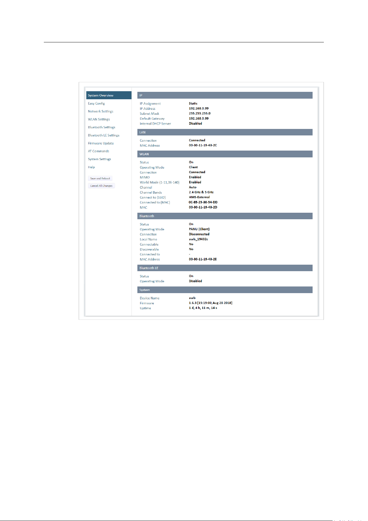
4.3.1 System Overview
Fig. 6 System Overview page
The System Overview page shows the current settings and connection status for the wired and
wireless interfaces. The different parameters are explained in the descriptions of each settings
page in this manual.
The Help page describes AT commands that can be used for advanced configuration.
Save and Reboot This button will be enabled if the unit must be restarted to apply a change.
Cancel All Changes Resets parameter changes that have not been applied.
®
Anybus
Wireless Bridge II™User Manual
SCM-1202-032 2.4 en-US
Page 15
Configuration 13 (46)
4.3.2 Easy Config
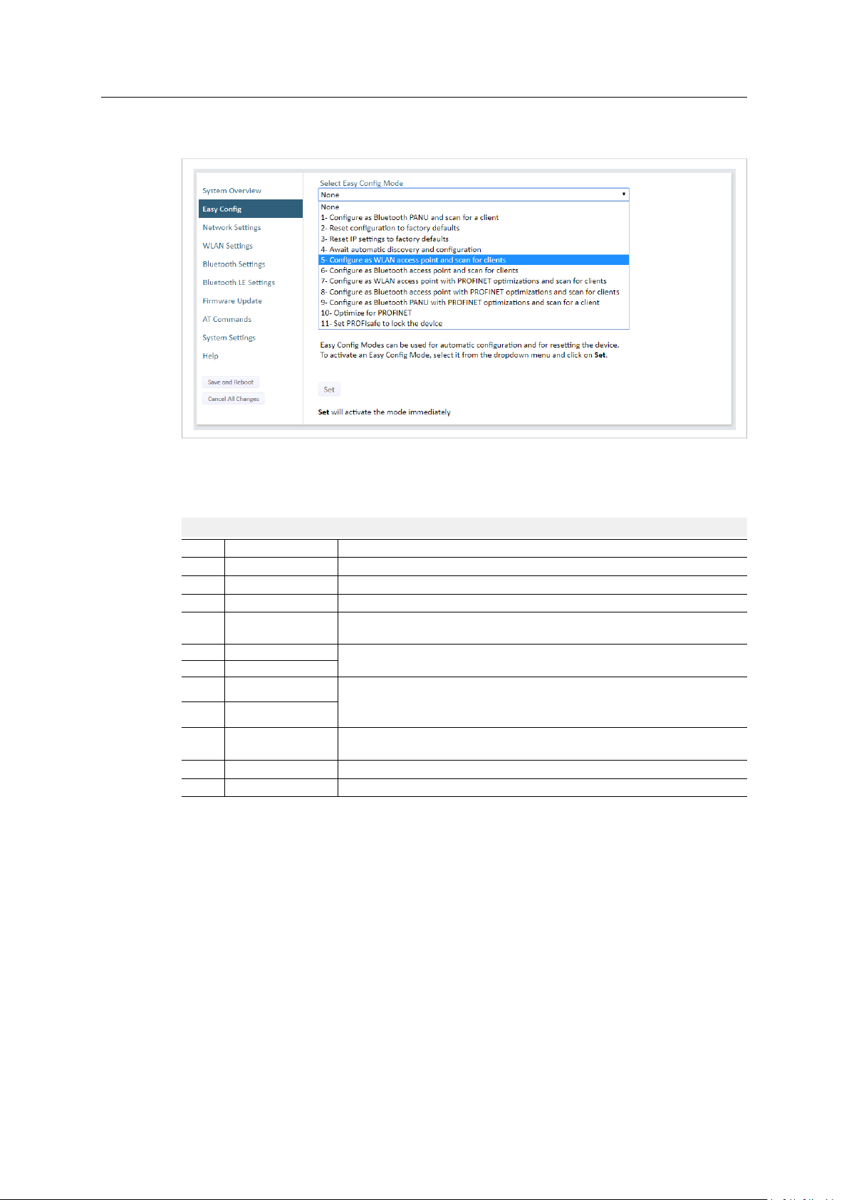
Fig. 7 Easy Config page
To activate an Easy Config mode, select it from the dropdown menu and click on Set. The mode
will be activated immediately.
Easy Config Modes
EC
Role Description
1 Bluetooth PANU
–
2
–
3
4
Client
5 WLAN AP
6
Bluetooth NAP
7 WLAN AP
8 Bluetooth NAP
9
Bluetooth PANU
(any) Apply PROFINET optimization and restart.
10
(any)
11
Configure as Bluetooth client and scan for another client (PANU–PANU).
Reset configuration to factory defaults.
Reset IP settings to factory defaults.
Wait for automatic configuration.
Configure units in mode 4 as clients.
Configure units in mode 4 as clients.
Restart as access point and connect clients.
Restart as access point and connect clients.
Apply PROFINET optimization to all units.
Configure as Bluetooth client and scan for another client (PANU–PANU).
Apply PROFINET optimization to both units.
Enable PROFIsafe mode.
®
Anybus
Wireless Bridge II™User Manual
SCM-1202-032 2.4 en-US
Page 16

Configuration 14 (46)
Notes:
• Mode 1 will scan for units in mode 4. When a unit in mode 4 is detected, the scanning unit
will configure itself as a Bluetooth PANU client, send a connection configuration to the
detected unit, and restart. The detected unit will also restart and attempt to connect to the
first unit as a PANU client.
• Modes 5, 6, 7 and 8 will scan for units in mode 4. The detected units will be reconfigured as
clients and the scanning unit will restart as an access point. The clients will then restart and
connect to the access point.
• Modes 7 and 8 will additionally apply PROFINET optimization to all the units. PROFINET
messages will then have priority over TCP/IP frames.
• Mode 11 locks the unit in PROFIsafe mode where the configuration cannot be changed
without physical access. To cancel this mode the unit must be restored to factory defaults
by pressing and holding the MODE button.
• Modes 10 and 11 will be added to the configuration without changing any other settings.
• Modes 1 and 9 will listen for 40 seconds or until a configuration is established.
• Modes 4 will listen for 120 seconds or until receiving a configuration.
• Modes 5, 6, 7 and 8 will time out after 120 seconds.
Anybus®Wireless Bridge II™User Manual
SCM-1202-032 2.4 en-US
Page 17

Configuration 15 (46)
4.3.3 Network Settings
Fig. 8 Network Settings page
IP Assignment
IP Address Static IP address for the unit
Subnet Mask Subnet mask when using static IP
Default Gateway Default gateway when using static IP
Internal DHCP Server Disabled: No internal DHCP functionality
Select static or dynamic IP addressing (DHCP)
The browser should automatically be redirected to the new address after clicking on
Save and Reboot (not supported by all browsers).
DHCP Relay Enabled: The unit can receive a DHCP request on one interface and resend
it to a DHCP server located on one of the other interfaces.
Only a single DHCP server can be active for all the connected interfaces.
If WLAN is used, the forwarding mode must be set to Layer 3 IP Forward.
DHCP Server Enabled: Activates an internal DHCP server. This option is only available
when IP Assignment is set to Static.
To avoid IP address conflict if a DHCP server is already active on the network, use the
DHCP Interfaces setting to limit the internal DHCP server to the correct interface.
®
Anybus
Wireless Bridge II™User Manual
SCM-1202-032 2.4 en-US
Page 18

Configuration 16 (46)
DHCP Interfaces The DHCP Interfaces function is available when Internal DHCP Server > DHCP Server
Enabled is selected.
All: By default, the DHCP Interfaces function is set to use all interfaces.
Wired Ethernet: The internal DHCP server only listens for clients on the wired Ethernet
interface.
Wireless Interfaces: The internal DHCP server listens for clients on all supported wireless
interfaces (WLAN/Bluetooth).
Start Address (Y) The internal DHCP server will assign up to 7 IP addresses starting from X.X.X.Y, where X
is taken from the current static IP address setting, and Y is the value in Start Address.
Already allocated addresses will be skipped, including the address of the unit itself. The
subnet mask setting will be ignored.
Examples:
IP Address: 192.168.0.99, Start Address: 101
DHCP range = 192.168.0.101 – 192.168.0.107
IP Address: 192.168.0.103, Start Address: 101
DHCP range = 192.168.0.101 – 192.168.0.108
7 addresses are allocated but the address of the unit is skipped.
®
Anybus
Wireless Bridge II™User Manual
SCM-1202-032 2.4 en-US
Page 19

Configuration 17 (46)
4.3.4 WLAN Settings - Client
Fig. 9 WLAN Settings - Client
Enable
Operating Mode Choose operation as WLAN Client or Access Point. If Access Point is selected, additional
Channel Bands Choose to scan only the 2.4 GHz or 5 GHz channel band, or both (default).
Enable/disable the WLAN interface.
settings will be available.
The unit can be configured to scan on both the 2.4 GHz and 5 GHz channel bands but can only
communicate on one band at a time.
Scan for Networks Click to scan the selected frequency band(s) for discoverable WLAN networks.
Connect to SSID
Authentication Mode
Passkey
Username, Domain,
Passphrase
Select a network from the dropdown menu to connect to it.
To connect manually to a network, enter its SSID (network name) here. This can be used
if the network does not broadcast its SSID.
Select the authentication/encryption mode required by the network.
Open = No encryption or authentication
Enter the passkey when using WPA/WPA2-PSK or WEP64/128.
Authentication details when using LEAP or PEAP (WPA2 Enterprise).
®
Anybus
Wireless Bridge II™User Manual
SCM-1202-032 2.4 en-US
Page 20

Configuration 18 (46)
Advanced Settings
Bridge Mode Layer 2 tunnel = All layer 2 data will be bridged over WLAN.
Use when multiple devices on both sides of an Ethernet network bridge must be able to
communicate via WLAN (many-to-many).
Only works between Anybus Wireless Bolt or Wireless Bridge II devices.
Layer 2 cloned MAC only = Layer 2 data from only a single MAC address (specified
below) will be bridged over WLAN (many-to-one).
Layer 3 IP forward (default) = IP data from all devices will be bridged over WLAN.
This mode must be used when using the DHCP Relay function.
When using Layer 3 IP forward in an enterprise network, such as a Cisco Wireless LAN
Controller, the connectivity may be reduced.
The cause may be:
• Multiple devices sharing a single wireless interface is not typically supported
without special configuration.
• The network cannot enforce a 1-to-1 mapping of IP to MAC addresses and must
allow propagation of broadcasted ARP messages over the wireless segment in order
to route traffic to the bridged devices.
If this for security or performance reasons is not acceptable, a setup with a single
Ethernet node connected to the Wireless Bridge is recommended.
Cloned MAC Address The MAC address to use with Layer 2 cloned MAC only (see above).
Cloned IP Address The IP address to use with Layer 2 cloned MAC only (see above).
MIMO
MIMO (multiple input, multiple output) antenna technology uses multiple antennas for
wireless communication in 802.11n.
MIMO is supported on units with internal antennas only. Radio communication will not
function if MIMO is enabled on units with connector for external antenna.
WLAN Roaming
Anybus Wireless Bridge II supports Fast Roaming according to IEEE 802.11r. This enables a WLAN
client to roam quicker between WLAN Access Points that have the same SSID and support IEEE
802.11r. Fast Roaming is enabled as default but can be permanently disabled using AT commands.
See the AT Commands Reference Guide or the Help page in the web interface for more
information about how to set up WLAN roaming.
Anybus®Wireless Bridge II™User Manual
SCM-1202-032 2.4 en-US
Page 21

Configuration 19 (46)
WLAN Channels and World Mode (Client Mode only)
Which channels are available for WLAN communication is restricted by the regulatory domain
where the unit is operating. Anybus Wireless Bridge II supports regulatory domain detection
according to the IEEE 802.11d specification.
The unit is initially set in World Mode which enables only the universally allowed channels in the
2.4 GHz and 5 GHz bands (see the table below). World Mode can be disabled and additional
channels added using AT commands. The unit will then search for country information during the
scan. If the scan indicates that the unit is operating within either the European (ETSI) or North
American (FCC) regulatory domains, the additional channels will be enabled. A new scan will be
performed every hour to update the regulatory domain.
If no country information or conflicting information is detected, the unit will revert to World
Mode. The unit must then be restarted to update the regulatory domain.
See the AT Commands Reference Guide or the Help page in the web interface for more
information about how to use AT commands.
Regulatory domains and WLAN channels
2.4 GHz 5 GHz
WORLD 1–11 36, 40, 44, 48, 52, 56, 60, 64, 100, 104, 108, 112, 116, 132, 136, 140
ETSI 1–11, 12, 13 36, 40, 44, 48, 52, 56, 60, 64, 100, 104, 108, 112, 116, 120, 124, 128, 132,
FCC 1–11 36, 40, 44, 48, 52, 56, 60, 64, 100, 104, 108, 112, 116, 132, 136, 140
136, 140
Notes
• The maximum output power will be reduced on some channels depending on regulatory
requirements.
• WLAN communication may take a longer time to establish during startup if World Mode is
disabled and additional channels are used.
Anybus®Wireless Bridge II™User Manual
SCM-1202-032 2.4 en-US
Page 22

Configuration 20 (46)
4.3.5 WLAN Settings - Access Point
Fig. 10 WLAN Settings - Access Point
The following settings are specific for Access Point mode:
Network (SSID) Enter an SSID (network name) for the Wireless Bridge.
If this entry is left blank, the unit will generate an SSID which includes the last 6
characters of the MAC ID.
Authentication Mode
WPA2 Passkey Enter a string in plain text or hexadecimal format to use for authentication.
Channel Bands, Channel Select the WLAN channel band and channel to use for the access point.
Select the authentication/encryption mode to use for the access point.
Open = No encryption or authentication
WPA2 = WPA2 PSK authentication with AES/CCMP encryption
Regular (plain text) passwords must be between 8 and 63 characters.
All characters in the ASCII printable range (32–126) are allowed, except
" (double quote) , (comma) and \ (backslash).
Hexadecimal passwords must start with 0x and be exactly 64 characters.
See also the example passwords below.
Valid channels are 1 to 11 for the 2.4 GHz band and 36, 40, 44, 48 for the 5 GHz band.
Password examples
For plain text passwords a combination of upper and lower case letters, numbers, and special
characters is recommended.
Example of a strong plain text password:
uS78_xpa&43
Example of hexadecimal password:
0x000102030405060708090a0b0c0d0e0f101112131415161718191a1b1c1d1e1f
Do not use the example passwords above in a live environment!
Anybus®Wireless Bridge II™User Manual
SCM-1202-032 2.4 en-US
Page 23

Configuration 21 (46)
4.3.6 Bluetooth Settings – General
Fig. 11 Bluetooth Settings
Enable
Operating Mode
Local Name Identifies the unit to other Bluetooth devices. If left blank, the unit will use a default
Connectable Enable to make the unit accept connections initiated by other Bluetooth devices.
Discoverable Enable to make the unit visible to other Bluetooth devices.
Security Mode Disabled = No encryption or authentication.
Paired Devices Lists the currently connected Bluetooth devices.
Enable/disable the Bluetooth interface.
PANU (Client) = The unit will operate as a Bluetooth PAN (Personal Area Network) User
device. It can connect to another single Bluetooth PANU device or to a Bluetooth
Network Access Point.
NAP (Access Point) = The unit will operate as a Bluetooth Network Access Point. It can
connect to up to 7 Bluetooth PANU devices.
name including the last 6 characters of the MAC ID.
PIN = Encrypted connection with PIN code security. This mode only works between two
units of this type and brand (not with third-party devices). PIN codes must consist of 4 to
6 digits.
Just Works = Encrypted connection without PIN code.
®
Anybus
Wireless Bridge II™User Manual
SCM-1202-032 2.4 en-US
Page 24

Configuration 22 (46)
4.3.7 Bluetooth Settings – PANU Mode
Fig. 12 Bluetooth Settings – PANU
PANU mode only
Scan for Devices Scans the network for discoverable Bluetooth devices. To connect to a device, select it
Connect To
Connection Scheme Choose whether to select a Bluetooth device by MAC address (default) or Name when
MAC/Name
from the dropdown menu when the scan has completed.
Used when connecting manually to a NAP or PANU device.
connecting manually.
Connecting to MAC will lock the connection to a specific hardware while connecting to
Name allows for more flexibility.
MAC address or Name of the Bluetooth device to connect to.
®
Anybus
Wireless Bridge II™User Manual
SCM-1202-032 2.4 en-US
Page 25

Configuration 23 (46)
4.3.8 Bluetooth Settings – NAP Mode
Fig. 13 Bluetooth settings – NAP
NAP mode only
Bridge Mode Standard = Default mode.
Layer 3 IP forward = IP data will be bridged over Bluetooth.
This mode must be used when connecting to an Android device over Bluetooth. The
network must have an active DHCP server.
List Nearby Devices Scans the network and lists discoverable Bluetooth devices.
Pairing cannot be initiated in NAP mode.
®
Anybus
Wireless Bridge II™User Manual
SCM-1202-032 2.4 en-US
Page 26

Configuration 24 (46)
4.3.9 Bluetooth LE Settings
Fig. 14 Bluetooth LE settings
Bluetooth LE Settings
Operating Mode Disabled = Bluetooth LE disabled (default)
Central = Bluetooth LE Central operating mode enabled
Peripheral = Bluetooth LE Peripheral operating mode enabled. This requires that the
WLAN interface is disabled.
Connectable No = Connectable is disabled (default)
Yes = Enables the Wireless Bridge to search, connect and transfer data with another
Bluetooth-capable device.
Discoverable No = Discoverable is disabled (default)
Yes = Enables the Wireless Bridge to pair with another Bluetooth-capable device.
Please refer to the AT Commands Reference Guide or select Help in the main menu for more
information about using Bluetooth LE.
Bluetooth must be enabled on the Bluetooth Settings page to use Bluetooth LE.
Anybus®Wireless Bridge II™User Manual
SCM-1202-032 2.4 en-US
Page 27

Configuration 25 (46)
4.3.10 Firmware Update
To update the firmware in the unit, click on Browse to select a downloaded firmware file, then
click on Send to send it to the unit.
Fig. 15 Firmware update in progress
Both progress bars will turn green when the firmware update has been completed. The unit will
then reboot automatically.
Fig. 16 Firmware update completed
Updating the firmware will not change the configuration settings.
Anybus®Wireless Bridge II™User Manual
SCM-1202-032 2.4 en-US
Page 28

Configuration 26 (46)
4.3.11 AT Commands
Fig. 17 AT Commands
AT commands can be used for setting advanced parameters that are not accessible in the web
interface, to read out parameters in text format, and for batch configuration using command
scripts.
Enter or paste the commands into the text box, then click on Send. The result codes will be
displayed below the text box.
Click on Help for a complete list of supported AT commands.
Anybus®Wireless Bridge II™User Manual
SCM-1202-032 2.4 en-US
Page 29

Configuration 27 (46)
4.3.12 System Settings
Fig. 18 System Settings
Device Info
Device Name
Password Enter a password for accessing the web interface.
Reboot System Reboots the system without applying changes.
Cancel All Changes Restores all parameters in the web interface to the currently active values.
Factory Reset
Enter a descriptive name for the unit.
Resets the unit to the factory default settings and reboots.
Setting a secure password for the unit is strongly recommended.
Settings Backup
Create Settings Backup Click on Generate to save the current configuration to a file on your computer.
Restore Settings
General Configuration
Click on Choose file and select a previously saved configuration, then click on Load. The
settings in the saved configuration will be applied and the unit will reboot.
Reboot System Reboots the system without applying changes.
Cancel All Changes Restores all parameters in the web interface to the currently active values.
Factory Reset
®
Anybus
Wireless Bridge II™User Manual
Resets the unit to the factory default settings and reboots.
SCM-1202-032 2.4 en-US
Page 30

Configuration 28 (46)
4.4 Factory Restore
Any one of these actions will restore the factory default settings:
• Clicking on Factory Restore on the System Settings page
• Executing Easy Config Mode 2
• Issuing the AT command AT&F and then restarting the unit
• Holding MODE pressed for >10 seconds and then releasing it
• Applying voltage to the digital input for >10 seconds
Default Network Settings
IP Assignment Static
IP Address
Subnet Mask
Default Gateway
Internal DHCP Server Disabled
DHCP Interfaces All
Default WLAN Settings
Operating Mode Client
Channel Bands
Authentication Mode
Channel
Bridge Mode Layer 3 IP forward
MIMO
192.168.0.99
255.255.255.0
192.168.0.99
2.4 GHz & 5 GHz
WPA/WPA2–PSK
Auto
AWB3000: Enabled
AWB3010: Disabled
Default Bluetooth Settings
Operating Mode PANU (Client)
Local Name [generated from MAC address]
Connectable
Discoverable
Security Mode Just works
Bluetooth LE Operating Mode: Disabled
No
No
Connectable: No
Discoverable: No
®
Anybus
Wireless Bridge II™User Manual
SCM-1202-032 2.4 en-US
Page 31

Appendix A: Configuration Examples 29 (46)
A Configuration Examples
A.1 Ethernet Bridge via WLAN or Bluetooth®(Easy Config)
Fig. 19 Ethernet bridge
This example describes how to connect two Ethernet network segments via WLAN or Bluetooth
using Easy Config.
Configuration
1. Power on the first unit and wait for the LEDs to light up and go out, then press MODE and
release it immediately.
2. Press MODE repeatedly until only LED C is lit (Mode 4), then confirm by pressing and
holding MODE for 2 seconds.
This unit will now be discoverable and open for automatic configuration.
3. Power on the second unit and wait for the LEDs to light up and go out, then press MODE
and release it immediately.
4. Press MODE repeatedly on the second unit until A + C (Mode 5/WLAN) or B + C (Mode 6/
Bluetooth) are lit, then confirm by pressing and holding MODE for 2 seconds.
Unit 2 will now discover and configure unit 1 as a client and configure itself as an access
point. Unit 1 will be assigned the first free IP address in the same Ethernet subnet as unit 2.
Adding More Devices
Up to 6 additional clients can be added by repeating the procedure. Each new client will be
assigned the next free IP address in the current subnet.
Anybus®Wireless Bridge II™User Manual
SCM-1202-032 2.4 en-US
Page 32

Appendix A: Configuration Examples 30 (46)
A.2 PROFINET networking via Bluetooth
Configuration with Easy Config
Fig. 20 PROFINET wireless network
This example describes how to connect a PROFINET IO device and a PROFINET PLC over
Bluetooth using two Wireless Bridges and Easy Config.
The Wireless Bridges will be configured with PROFINET optimization, which means that
PROFINET messages will have priority over TCP/IP frames.
See the respective documentation for the IO device and PLC on how to configure them for
PROFINET communication.
Configuration
1. Reset both Wireless Bridges to the factory default settings.
®
2. Connect Wireless Bridge 1 to the IO device and Wireless Bridge 2 to the PLC.
3. Set Wireless Bridge 1 to Easy Config Mode 4.
This unit will now be discoverable and open for automatic configuration.
4. Set Wireless Bridge 2 to Easy Config Mode 8
This unit should now automatically discover and configure unit 1 as a Bluetooth client, and
configure itself as an access point. Both units will be optimized for PROFINET.
The IO device should now be able to communicate with the PLC as if using a wired connection.
Adding More Devices
Up to 6 additional clients can be added by repeating the procedure. Each new client will be
assigned the next free IP address within the current subnet.
The IO cycle update time for each IO device must be set to ≥ 64 ms.
Anybus®Wireless Bridge II™User Manual
SCM-1202-032 2.4 en-US
Page 33

Appendix A: Configuration Examples 31 (46)
A.3 EtherNet/IP™Networking via Bluetooth
Configuration with Easy Config
Fig. 21 EtherNet/IP wireless network
This example describes how to connect an EtherNet/IP IO device and an EtherNet/IP PLC over
Bluetooth using two Wireless Bridges and Easy Config.
See the respective documentation for the IO device and PLC on how to configure them for
EtherNet/IP communication.
Configuration
1. Reset both Wireless Bridges to the factory default settings.
2. Connect Wireless Bridge 1 to the IO device and Wireless Bridge 2 to the PLC.
3. Set Wireless Bridge 1 to Easy Config Mode 4.
®
This unit will now be discoverable and open for automatic configuration.
4. Set Wireless Bridge 2 to Easy Config Mode 6
This unit should now automatically discover and configure unit 1 as a Bluetooth client, and
configure itself as an access point.
The IO device should now be able to communicate with the PLC as if using a wired connection.
Adding More Devices
Up to 6 additional clients can be added by repeating the procedure. Each new client will be
assigned the next free IP address within the current subnet.
The Requested Packet Interval (RPI) for each IO device must be set to ≥ 64 ms.
Anybus®Wireless Bridge II™User Manual
SCM-1202-032 2.4 en-US
Page 34

Appendix A: Configuration Examples 32 (46)
A.4 Ethernet network to existing WLAN
Fig. 22 Connecting to a WLAN
Before You Begin
This example describes how to connect a machine with an internal Ethernet network to an
existing WLAN.
This setup allows traffic on network layer 3, but not layer 2. This means that TCP/IP based
protocols such as EtherNet/IP, Modbus TCP and BACnet can be used on the WLAN, but not
protocols that use layer 2 traffic, such as PROFINET.
When this setup is used in an enterprise network, such as a Cisco Wireless LAN Controller, the
connectivity may be reduced.
The cause may be:
• Multiple devices sharing a single wireless interface is not typically supported without special
configuration.
• The network cannot enforce a 1-to-1 mapping of IP to MAC addresses and must allow
propagation of broadcasted ARP messages over the wireless segment in order to route
traffic to the bridged devices.
If this for security or performance reasons is not acceptable, a setup with a single Ethernet
node connected to the Wireless Bridge is recommended.
Configuration
1. Reset the Wireless Bridge to the factory default settings.
2. In Network Settings, configure the IP settings as required by the wireless network.
3. If the network uses DHCP, select DHCP Relay Enabled.
Anybus®Wireless Bridge II™User Manual
SCM-1202-032 2.4 en-US
Page 35

Appendix A: Configuration Examples 33 (46)
WLAN Settings for Small Office/Home Office Network
If the setup is used in a small office/home office network, follow these steps:
1. In WLAN Settings, click on Scan for Networks.
2. When the scan has completed, select the wireless network from the dropdown list.
3. If required, select the authentication mode and enter the passkey for the wireless network.
WLAN Bridge Mode must be set to Layer 3 IP forward (the default setting).
4. Click on Save and Reboot.
Result
→ The Ethernet network should now be able to access the WLAN access point.
WLAN Settings for Enterprise Network
If the setup is used in an enterprise network, follow these steps:
1. In WLAN Settings, set Bridge Mode to Layer 2 cloned MAC only.
2. Enter the MAC address of the PLC in the Cloned MAC Address field.
3. Enter the IP address of the PLC in the Cloned IP Address field.
4. Click on Save and Reboot.
Result
→ The Wireless Bridge will now function as a WLAN interface for the PLC using the MAC
address of its Ethernet interface.
Anybus®Wireless Bridge II™User Manual
SCM-1202-032 2.4 en-US
Page 36

Appendix A: Configuration Examples 34 (46)
A.5 Adding single Ethernet node to WLAN
Fig. 23 Adding WLAN connectivity
This example shows how to connect a PLC with an Ethernet network interface to an existing
WLAN with support for layer 2 and layer 3 traffic. The WLAN interface in the Wireless Bridge will
clone the MAC address of the Ethernet interface in the PLC.
Only a single Ethernet node will be able to communicate via a third-party WLAN access point in
this setup.
Configuration
1. Reset the Wireless Bridge to the factory default settings.
2. In Network Settings, configure the IP settings as required by the wireless network.
3. In WLAN Settings, click on Scan for Networks.
4. When the scan has completed, select the wireless network from the dropdown list.
5. If required, select the authentication mode and enter the passkey for the wireless network.
6. Click on Save and Reboot.
7. Check the System Overview page to confirm that the WLAN connection is established
before continuing.
DO NOT SKIP THIS STEP! After the final steps of the configuration procedure the web
interface may no longer be accessible from the network without doing a factory reset.
8. In WLAN Settings, set Bridge Mode to Layer 2 cloned MAC only.
9. Enter the MAC address of the PLC in the Cloned MAC Address field.
10. Enter the IP address of the PLC in the Cloned IP Address field.
11. Click on Save and Reboot.
The Wireless Bridge will now function as a WLAN interface for the PLC using the MAC address of
its Ethernet interface.
Anybus®Wireless Bridge II™User Manual
SCM-1202-032 2.4 en-US
Page 37

Appendix A: Configuration Examples 35 (46)
A.6 Accessing PLC via WLAN from Handheld Device
Fig. 24 Accessing a PLC from a handheld device using WLAN
This example describes how to use a Wireless Bridge to access the web interface of a PLC on a
wired network from a tablet or smartphone which uses DHCP. The Wireless Bridge will function
as a WLAN access point.
Please refer to the documentation for the handheld device and PLC on how to configure their
respective network settings.
Configuration
1. Reset the Wireless Bridge to the factory default settings.
2. In Network Settings, configure the IP settings as required:
Option if the wired network uses DHCP:
a. Select DHCP Relay Enabled. The DHCP server on the network will now be able to
allocate an IP address to the handheld device.
Option if the wired network uses static IP:
To avoid IP address conflict if a DHCP server is already active on the network, use the
DHCP Interfaces setting to limit the internal DHCP server to the correct interface.
a. Select DHCP Server Enabled.
b. Select an interface from the DHCP Interfaces dropdown menu.
c. Enter a Start Address for DHCP addressing. Make sure that the address range does not
contain any existing addresses on the network.
→ The Wireless Bridge will now function as a DHCP server and allocate an IP address to
the handheld device over WLAN.
Anybus®Wireless Bridge II™User Manual
SCM-1202-032 2.4 en-US
Page 38

Appendix A: Configuration Examples 36 (46)
3. In WLAN Settings, set Operating Mode to Access Point.
Fig. 25 WLAN Settings
4. Enter a unique SSID (network name) for the new wireless network.
5. Set Authentication Mode to WPA2 and enter a passkey.
6. Select a Channel band and a Channel.
7. Click on Save and Reboot.
You should now be able to connect to the SSID of the Wireless Bridge on your handheld device
and access the PLC by by entering its IP address in a browser.
Anybus®Wireless Bridge II™User Manual
SCM-1202-032 2.4 en-US
Page 39

Appendix B: Technical Data 37 (46)
B Technical Data
B.1 Hardware Specifications
Order code
Wired Interface type Ethernet
Antenna
Dimensions (LxWxH)
Weight
Operating temperature -40 to +65 °C
Storage temperature
Humidity EN 600068-2-78: Damp heat, +40 °C, 93 % humidity for 4 days
Vibration See datasheet
Housing material Plastic (see datasheet for details)
Protection class
Mounting
Power connector
Ethernet connector M12 female D-coded
Power supply 9–30 VDC (-5 % +20 %)
Power consumption
AWB3000 AWB3010
3 internal antennas:
2.4 GHz
2.4 GHz MIMO
5 GHz
93 x 68 x 33.2 mm
120 g
-40 to +85 °C
IP65
Screw mount or DIN rail using optional clip
M12 male A-coded
Cranking 12 V (ISO 7637-2:2011 pulse 4)
Reverse polarity protection
0.7 W (idle), 1.7 W (max)
1 external antenna:
2.4 GHz + 5 GHz dual band
®
Anybus
Wireless Bridge II™User Manual
SCM-1202-032 2.4 en-US
Page 40

Appendix B: Technical Data 38 (46)
B.2 Communication
Ethernet
Ethernet interface
Ethernet protocols
Wireless LAN
Wireless standards IEEE 802.11 a, b, g, n, d, r
Operation modes Access point or client
Fast roaming
Max. number of clients
for access point
WLAN channels
RF output power
Power consumption 54 mA @ 24 VDC
Net data throughput 20 Mbps.
Link speed Max 130 Mbps (802.11n 2x2 MIMO)
Security
10/100BASE-T with automatic MDI/MDIX auto cross-over detection
IP, TCP, UDP, HTTP, LLDP, ARP, DHCP Client/Server, DNS support
Transparent transfer of PROFINET IO, EtherNet/IP, Modbus-TCP or any other TCP/UDP based
protocol
IEEE 802.11r (client)
7
2.4 GHz Access Point: 1–11
2.4 GHz Client: 1–11 + 12 & 13 depending on regulatory domain scan
5 GHz Access Point: 36–48 (U-NII-1)
5 GHz Client: 36-48 + 100–116, 132–140, 120–128 depending on regulatory domain scan. (UNII-1, U-NII-2, U-NII-2e)
18 dBm EIRP (including max antenna gain 3 dBi)
WEP 64/128, WPA, WPA-PSK and WPA2, TKIP and AES/CCMP, LEAP, PEAP including MS-CHAP
Classic Bluetooth
Wireless standards (profiles) PAN (PANU & NAP)
Operation modes Access point or Client
Max. number of clients
for access point
RF output power
Power consumption 36 mA @ 24 VDC
Net data throughput ~1 Mbps
Bluetooth version support Classic Bluetooth v2.1
Security Authentication & Authorization, Encryption & Data Protection, Privacy & Confidentiality, NIST
7
14 dBm EIRP (including max antenna gain 3 dBi)
Compliant, FIPS Approved
Bluetooth Low Energy
Wireless standards (profiles)
Operation modes Central or Peripheral (pending)
Max. number of clients
for Central
RF output power
Power consumption 36 mA @ 24 VDC
Net data throughput ~200 kbps
Bluetooth version support Bluetooth 4.0 dual-mode
Security AES-CCM cryptography
GATT
7
10 dBm EIRP (including max antenna gain 3 dBi)
®
Anybus
Wireless Bridge II™User Manual
SCM-1202-032 2.4 en-US
Page 41

Appendix B: Technical Data 39 (46)
B.3 Internal Antenna Characteristics
Anybus Wireless Bridge II has 3 independent quarter wave monopole antennas: 2.4 GHz MIMO,
5 GHz and 2.4 GHz. The following radiation diagrams show the characteristics of the different
antennas as measured under laboratory test conditions. The diagrams can be used as a general
guide for finding the optimal placement and orientation of the units.
If using the unit in Bluetooth mode, the 2.4 GHz antenna is used.
B.3.1 Internal Antenna Positions
The placement of the three antennas in the unit is as follows:
Anybus®Wireless Bridge II™User Manual
SCM-1202-032 2.4 en-US
Page 42

Appendix B: Technical Data 40 (46)
B.3.2 Lab Environment Diagrams
Overview
The following sections contain radiation measurements in different angles. According to the
picture below, the Azimuth plane is the horizontal spread of the radiation (A), Elevation 90° is the
vertical expansion (B) and Elevation 0° is the front to back expansion (C).
The diagrams show decibel (dB) relative to the Anybus Wireless Bridge II theoretical maximum
signal strength. Note that the 2.4 MIMO diagrams show the WLAN usage using both the 2.4 GHz
antennas simultaneously (the 2.4 GHz antenna and the 2.4 GHz MIMO antenna).
Azimuth (Horisontal) View
Anybus®Wireless Bridge II™User Manual
SCM-1202-032 2.4 en-US
Page 43

Appendix B: Technical Data 41 (46)
Front View – Elevation (Vertical)
Side View – Elevation (Vertical)
Anybus®Wireless Bridge II™User Manual
SCM-1202-032 2.4 en-US
Page 44
Appendix B: Technical Data 42 (46)
B.3.3 Real World Measurements
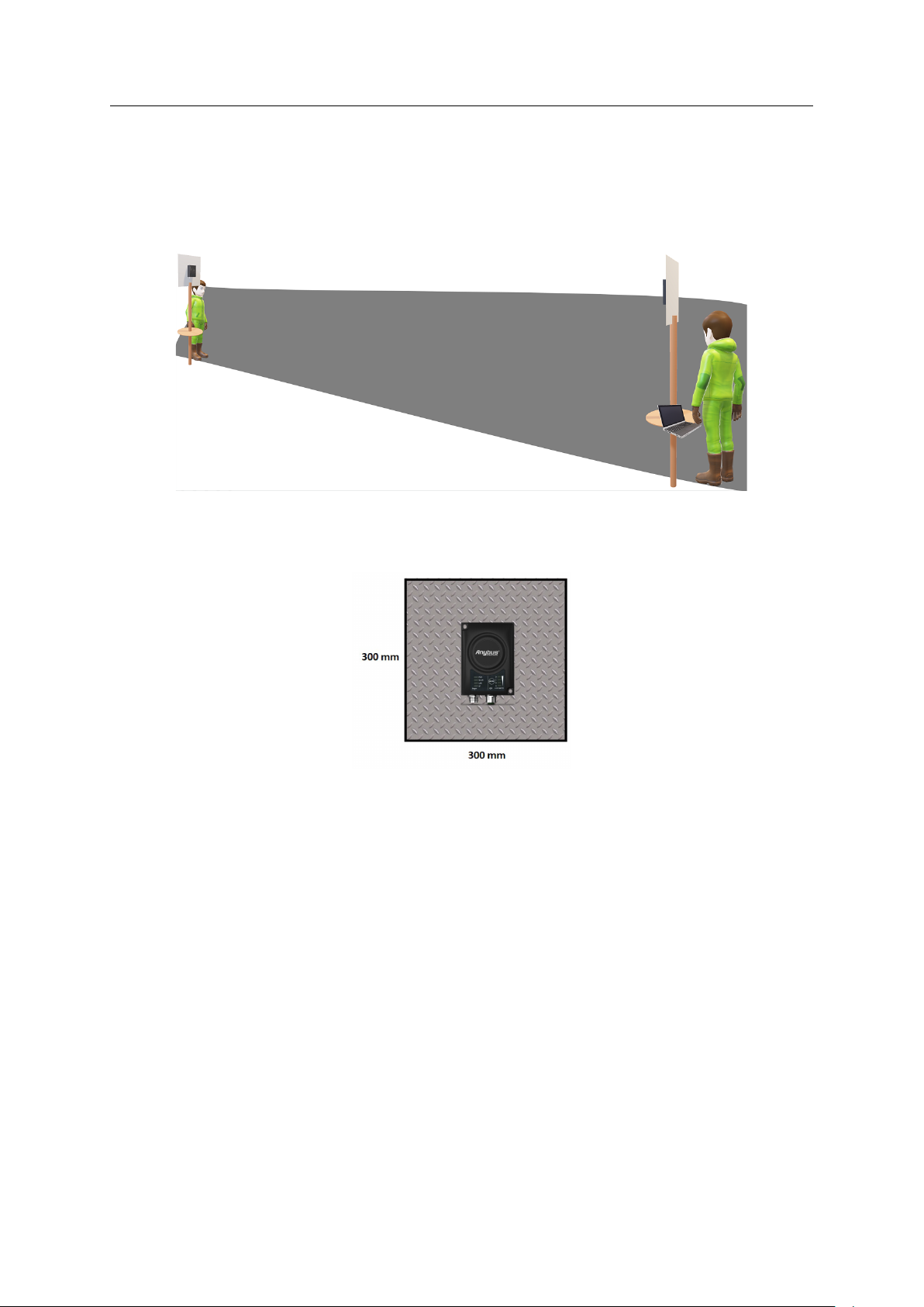
Azimuth (Horisontal) View with and without Backshield
This pattern was measured in an outdoor environment, on an open field with no disturbing
equipment or radiation. As such it describes how the radio coverage can vary in a real world
application. The measurements were set up according to the picture:
In this example, the measurements are made both with and without backshield. A backshield is a
metal surface of at least 300x300 mm, where the Anybus Wireless Bridge II is placed in the
center.
The backshield could be any flat metal surface, like a metal plate or a metal cabinet.
Anybus®Wireless Bridge II™User Manual
SCM-1202-032 2.4 en-US
Page 45

Appendix B: Technical Data 43 (46)
The measurements with backshield clearly shows that the backshield makes it possible to focus
the radio energy in any desired direction (away from the backshield).
Throughput Diagram
This diagram shows how data throughput decreases when distance increases. Note the huge
difference between using a backshield to focus the radio energy, and not using a backshield.
Using a backshield can greatly increase radio coverage if used correctly.
The diagram covers both the Anybus Wireless Bridge and the Anybus Wireless Bolt.
Anybus®Wireless Bridge II™User Manual
SCM-1202-032 2.4 en-US
Page 46

Appendix C: Wireless Technology Basics 44 (46)
C Wireless Technology Basics
Wireless technology is based on the propagation and reception of electromagnetic waves. These
waves respond in different ways in terms of propagation, dispersion, diffraction and reflection
depending on their frequency and the medium in which they are travelling.
To enable communication there should optimally be an unobstructed line of sight between the
antennas of the devices. However, the so called Fresnel Zones should also be kept clear from
obstacles, as radio waves reflected from objects within these zones may reach the receiver out
of phase, reducing the strength of the original signal (also known as phase cancelling).
Fresnel zones can be thought of as ellipsoid three-dimensional shapes between two wireless
devices. The size and shape of the zones depend on the distance between the devices and on the
signal wave length. As a rule of thumb, at least 60 % of the first (innermost) Fresnel zone must
be free of obstacles to maintain good reception.
Fig. 26 Fresnel zones
Area to keep clear of obstacles (first Fresnel zone)
Distance (d)
100 m 1.7 m 1.2 m
200 m 2.5 m 1.7 m
300 m 3.0 m 2.1 m
400 m 3.5 m 2.4 m
2.4 GHz (WLAN or Bluetooth) 5 GHz (WLAN)
Fresnel zone radius (r)
The wireless signal may be adequate even if there are obstacles within the Fresnel zones, as it
always depends on the number and size of the obstacles and where they are located. This is
especially true indoors, where reflections on metal objects may actually help the propagation of
radio waves. To reduce interference and phase cancelling, the transmission power of the unit
may in some cases have to be reduced to limit the range.
It is therefore recommended to use a wireless signal analysis tool for determining the optimal
placement and configuration of a wireless device.
Anybus®Wireless Bridge II™User Manual
SCM-1202-032 2.4 en-US
Page 47

This page intentionally left blank
Page 48

last page
© 2021 HMS Industrial Networks
Box 4126
300 04 Halmstad, Sweden
info@hms.se SCM-1202-032 2.4 en-US / 2021-03-31 / 22007
 Loading...