

Page 1
Anybus®Wireless Bolt IoT
Set Up IO-Link Master and Bolt IoT with MQTT
APPLICATION NOTE
SCM-1202-174 1.0 en-US ENGLISH
™
Page 2

Important User Information
Disclaimer
The information in this document is for informational purposes only. Please inform HMS Networks of any
inaccuracies or omissions found in this document. HMS Networks disclaims any responsibility or liability for any
errors that may appear in this document.
HMS Networks reserves the right to modify its products in line with its policy of continuous product development.
The information in this document shall therefore not be construed as a commitment on the part of HMS Networks
and is subject to change without notice. HMS Networks makes no commitment to update or keep current the
information in this document.
The data, examples and illustrations found in this document are included for illustrative purposes and are only
intended to help improve understanding of the functionality and handling of the product. In view of the wide range
of possible applications of the product, and because of the many variables and requirements associated with any
particular implementation, HMS Networks cannot assume responsibility or liability for actual use based on the data,
examples or illustrations included in this document nor for any damages incurred during installation of the product.
Those responsible for the use of the product must acquire sufficient knowledge in order to ensure that the product
is used correctly in their specific application and that the application meets all performance and safety requirements
including any applicable laws, regulations, codes and standards. Further, HMS Networks will under no circumstances
assume liability or responsibility for any problems that may arise as a result from the use of undocumented features
or functional side effects found outside the documented scope of the product. The effects caused by any direct or
indirect use of such aspects of the product are undefined and may include e.g. compatibility issues and stability
issues.
Anybus®Wireless Bolt IoT
™
SCM-1202-174 1.0 en-US
Page 3

Table of Contents
Page
1 Preface ................................................................................................................................. 3
1.1 About This Application Note .............................................................................................. 3
1.2 Target Audience.............................. ....... ....... ....... ....... ....... ..............................................3
1.3 Trademarks...................... ....... ....... ....... ....... ....... ............................................... ....... ......3
2 Preparation.......................................................................................................................... 4
2.1 Required Equipment.... ........................................................................... .......................... 4
2.2 Support and Resources ........................................ ....... ....... ....... ....... ................................. 4
3 Connecting the Devices....................................................................................................... 5
4 IO-Link Configuration .......................................................................................................... 6
4.1 Installing the LR DEVICE Application ..... ....... ............................................... ....... ....... ....... ....6
4.2 Load Data From IO-Link Master ....... ....... ........................................................................... . 7
4.3 IO-Link Master Configuration ..... ....... ....... ...................................................... ....... ....... ......8
4.4 Ifm Pushbutton Configuration ............................................................................................ 9
5 Wireless Bolt IoT Setup..................................................................................................... 10
6 Computer IP Configuration............................................................................................... 14
7 Publish Data From IO-Link ................................................................................................ 15
8 Verify Communication ...................................................................................................... 18
Anybus®Wireless Bolt IoT
™
SCM-1202-174 1.0 en-US
Page 4

This page intentionally left blank
Page 5
Preface 3 (20)
1 Preface
1.1 About This Application Note
Fig. 1
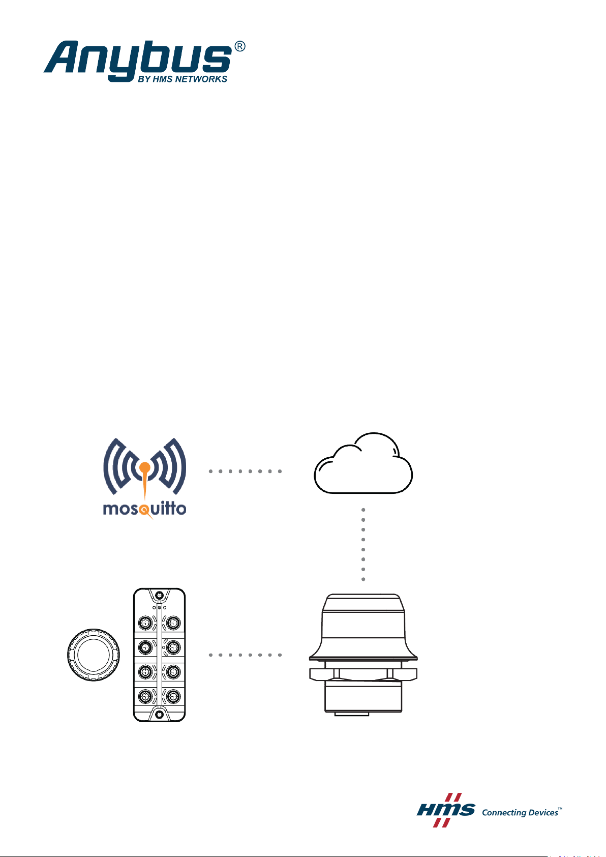
In this application note, we describe how to connect a ifm pushbutton to an IO-Link Master using
the Modbus TCP interface with a Wireless Bolt IoT by pushing the data from the push-button to
a MQTT-server/broker on the internet via the Wireless Bolt IoT.
1.2 Target Audience
It is recommended that the reader is familiar with the equipment and have a good knowledge of
wireless communication and network technology.
1.3 Trademarks
Anybus®is a registered trademark of HMS Networks AB.
All other trademarks are the property of their respective holders.
Anybus®Wireless Bolt IoT
™
SCM-1202-174 1.0 en-US
Page 6

Preparation
2 Preparation
2.1 Required Equipment
In this application note we use the following equipment:
4 (20)
Equipment Article Number Version
ifm IO-Link master with Modbus TCP
interface
ifm Capacitive illuminated pushbutton
ifm USB Stick with IO-Link parameter setting
software, LR DEVICE
ifm Power supply, 24 VDC with M12
connector
ifm Connection Cable
Anybus Wireless Bolt IoT black, NB-IoT, LTEM/CAT-M1, 2G GPRS/EDGE
IoT SIM-card Netmore M2M
Netgear ProSafe 5-Port Gigabit Switch
Power adapter, 12VDC
2 Ethernet Cables
AL1340
KT6101
QA0011
N/A N/A N/A
E12490
AWB1000
SP2824
GS105v4
N/A N/A N/A
N/A N/A N/A
AL1x4x_fw_mo_f7_v2.3.23
N/A N/A
N/A N/A
N/A
N/A N/A
N/A N/A
N/A N/A
Type
N/A
0.5 m PVCCable; M12/
RJ45 connector
Optional equipment
This kit can be used as an option to the AL1340, Ifm IO-Link master with Modbus TCP interface:
Equipment Article Number
ifm IO-Link master starter kit - MQTT JSON
ZZ1350
2.2 Support and Resources
For additional documentation and software downloads, FAQs, troubleshooting guides and
technical support, please visit www.anybus.com/support and ifm.com.
Have the product article number available, to search for the product specific support web page. You find
the product article number on the product cover.
Anybus®Wireless Bolt IoT
™
SCM-1202-174 1.0 en-US
Page 7
Connecting the Devices 5 (20)
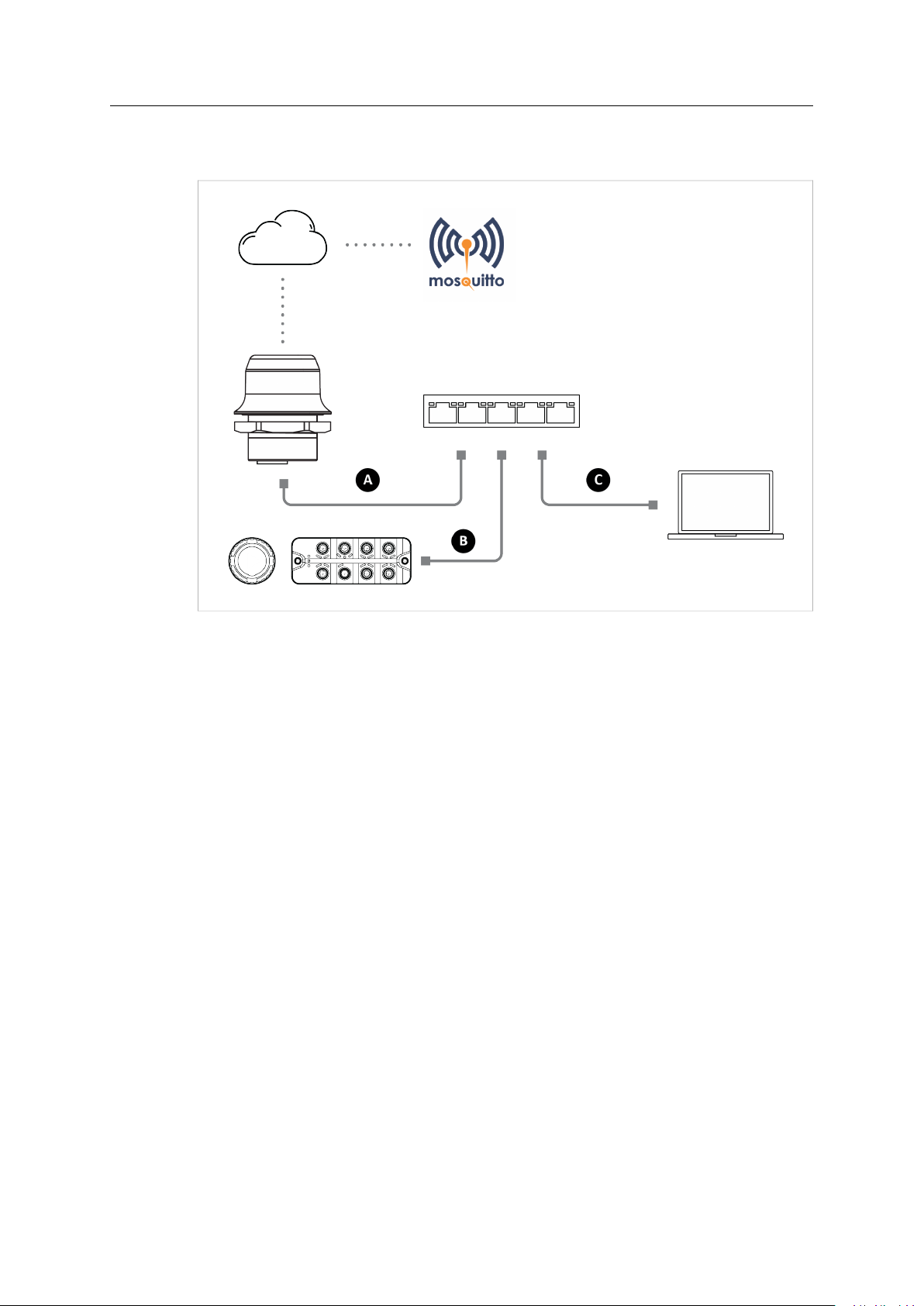
3 Connecting the Devices
Fig. 2
IP settings
The IP address of the IO-Link master needs to be configured before it can start to communicate
with the Wireless Bolt IoT, refer to IO-Link Configuration, p. 6.
Connect and configure one device at a time
Connect one device at a time to the switch and configure it, before continuing with the next
device and so on.
Connecting cables
• Connect the Wireless Bolt IoT to the switch with an ethernet cable (A).
• Connect the IO-Link master to the switch with the ifm connection cable (E12490) (B).
• Connect your computer to the switch with an ethernet cable (C).
IO-Link master ports used
• Connect the ifm connection cable (E12490) to port X23.
• Connect the ifm power supply to port X31.
• Connect the ifm pushbutton to port X01.
ifm power supply
Connect all the devices to the ifm power supply.
Anybus®Wireless Bolt IoT
™
SCM-1202-174 1.0 en-US
Page 8
IO-Link Configuration 6 (20)
4 IO-Link Configuration
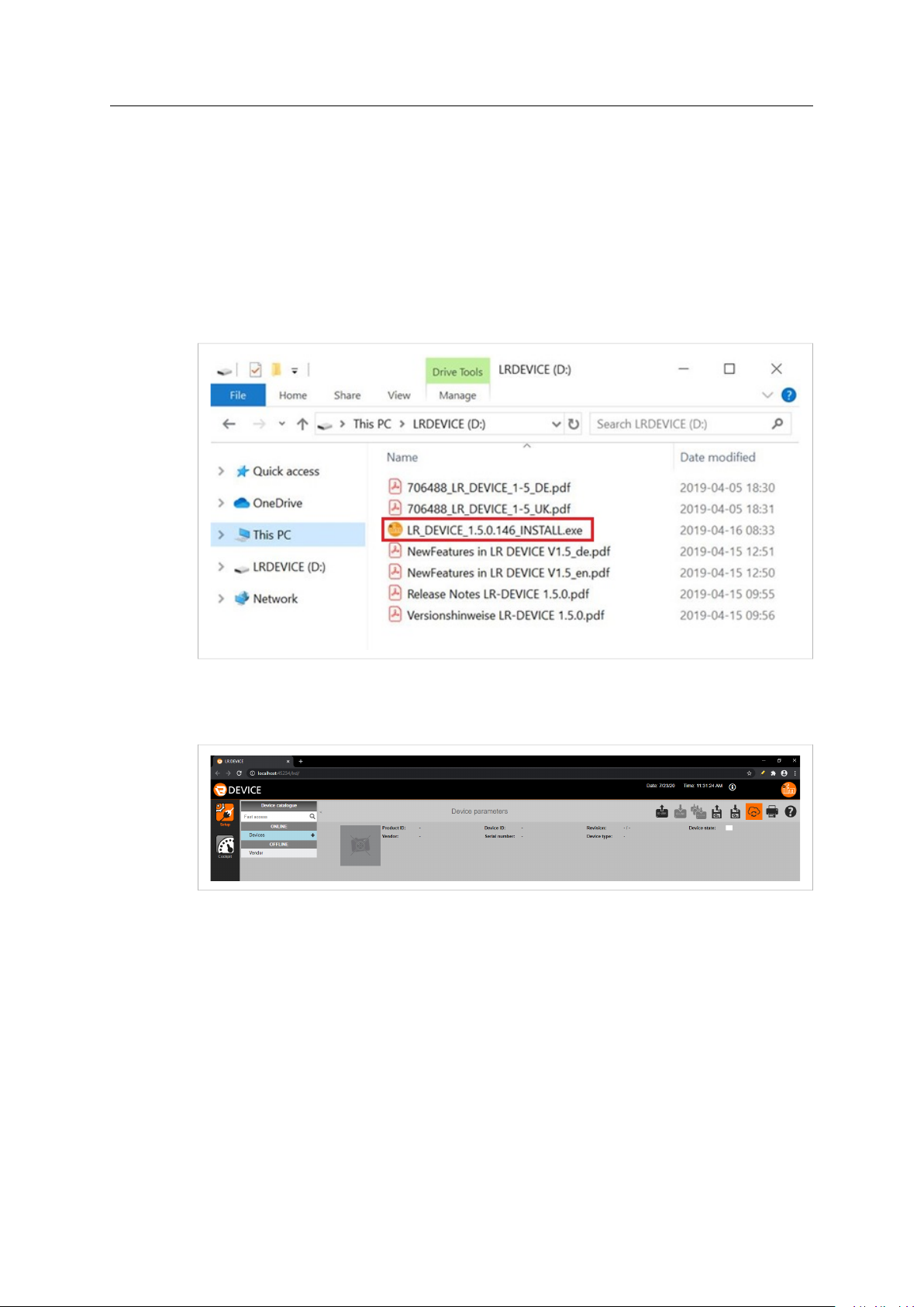
4.1 Installing the LR DEVICE Application
To configure the IO-Link master parameter settings, you need to install the LR DEVICE application
on your computer.
Procedure
1. Plug in the ifm USB-stick to your computer and download the LR DEVICE installation exe file.
2. Run the LR DEVICE installation exe file and follow the instructions on the screen.
Fig. 3
3. Navigate to the folder where the LR DEVICE was installed and start the application.
→ The LR DEVICE start screen opens.
Fig. 4
Anybus
®
Wireless Bolt IoT
™
SCM-1202-174 1.0 en-US
Page 9
IO-Link Configuration 7 (20)
4.2 Load Data From IO-Link Master
Before You Begin
The IO-Link master factory default IP address starts with 169.254.
When the DHCP client of the IO-Link master is enabled, the IO-Link master is assigned the IP
address 192.168.0.144 by the Wireless Bolt IoT.
Procedure
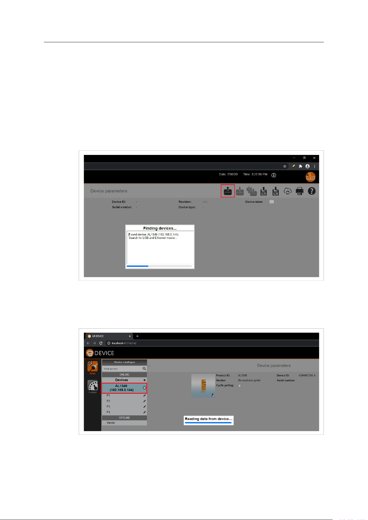
1. To search for IO-Link master, click Read from device in the top right menu.
→ The Finding devices pop-up window appears. Wait until a Found device appears,
showing the IO-Link master article number and IP address.
Fig. 5
2. To load data from the IO-Link master to the LR DEVICE application, click AL1340A in the
ONLINE menu.
→ The Reading data from device pop-up window appears. Wait until all the data has
been loaded from the IO-Link master.
Fig. 6
Anybus
®
Wireless Bolt IoT
™
SCM-1202-174 1.0 en-US
Page 10

IO-Link Configuration 8 (20)
4.3 IO-Link Master Configuration
In this section, we configure the IO-Link master IP address, Subnet mask and the Default gateway
IP address.
Before You Begin
DHCP server
Ensure that there is a DHCP server available on the network, where the IO-Link master is
connected.
If there is no DHCP server available when you reboot the IO-Link master, the device connected to
the IO-Link master will not be able to find it.
Static IP address
If the IO-Link master uses a static IP address:
• and is connected to a network with DHCP mode enabled, the IO-Link master will not be
configurable.
• ensure that the IP address is in the same subnet as the device connected to it.
IO-Link master factory default settings
IP address
Subnet mask
Gateway IP address
169.254.x.x
255.255.0.0
0.0.0.0
Procedure
Fig. 7
To configure the IO-Link master:
1. In the ONLINE menu, click AL1340.
2. Select the IoT tab, where the IO-Link master IoT parameters are listed.
3. Select DHCP from the DHCP drop-down menu.
4. To finish the configuration, click Write to device in the top right menu.
To make the changes take effect, you need to reboot the IO-Link master:
5. Disconnect the IO-Link master from power and then reconnecting it again.
Result
→ The IP address, Subnet mask and the Default gateway IP address are updated.
Anybus®Wireless Bolt IoT
™
SCM-1202-174 1.0 en-US
Page 11
IO-Link Configuration 9 (20)
4.4 Ifm Pushbutton Configuration
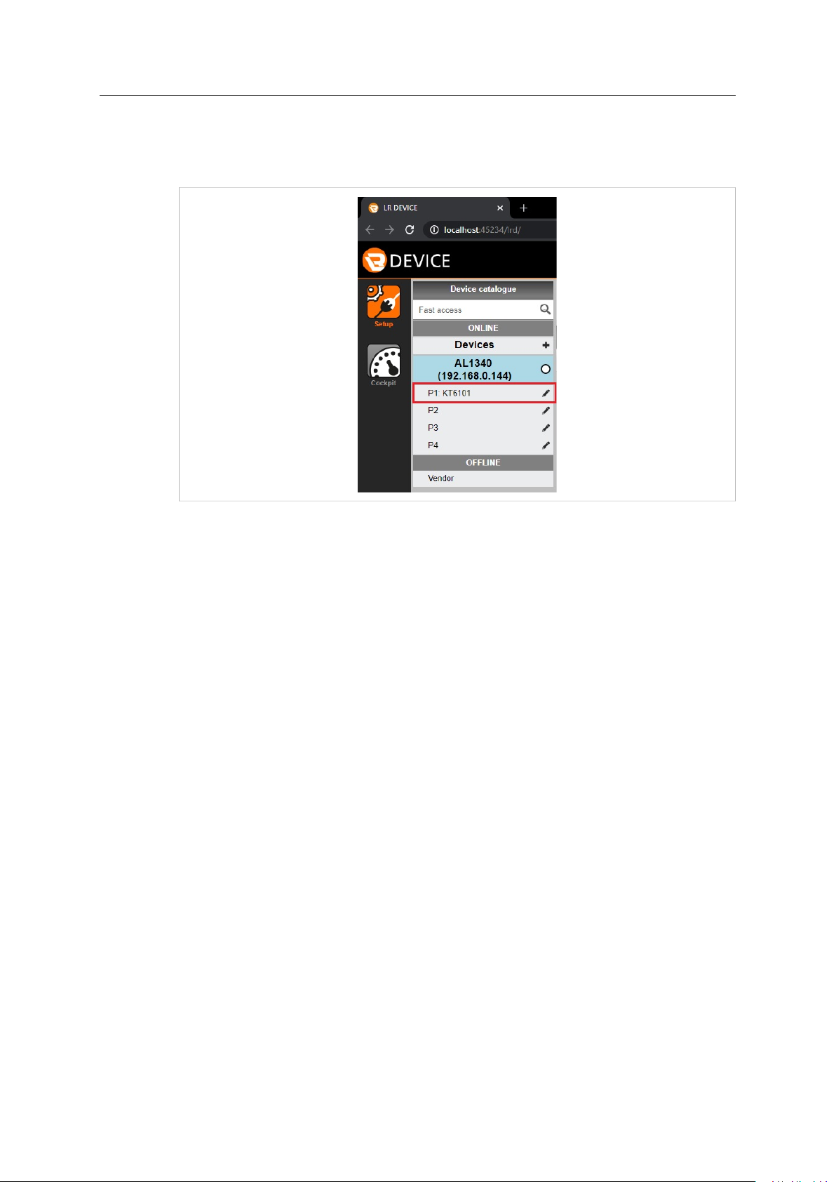
When the capacitive illuminated ifm pushbutton is connected to the IO-Link master, it appears in
the ONLINE menu.
Fig. 8
Procedure
To configure the ifm pushbutton settings:
1. Click on KT6101.
→ The LR DEVICE reads and shows the ifm pushbutton parameter values.
2. Configure the desired parameters.
3. To make the changes take effect, reboot the IO-Link master.
Anybus®Wireless Bolt IoT
™
SCM-1202-174 1.0 en-US
Page 12

Wireless Bolt IoT Setup 10 (20)
5 Wireless Bolt IoT Setup
Procedure
Connect the Wireless Bolt IoT to internet:
1. Insert SIM card
Insert a cellular SIM card in the
Wireless Bolt IoT SIM card holder.
Ensure that the SIM card contact surface
is facing towards the Ethernet port.
2. Connect to Computer and Power
a. Connect the Wireless Bolt IoT
Ethernet port to your computer.
b. Connect the Wireless Bolt IoT Power
connector to a power supply.
3. Wireless Bolt IoT IP settings
To access the Wireless Bolt IoT built-in
web interface, ensure that the
Wireless Bolt IoT IP address and your
computer IP address are within the same
IP address range.
Fig. 9
Fig. 10
The default IP address is 192.168.0.98.
Anybus®Wireless Bolt IoT
Fig. 11
™
SCM-1202-174 1.0 en-US
Page 13

Wireless Bolt IoT Setup 11 (20)
4. Access the Wireless Bolt IoT built-in web interface
The Wireless Bolt IoT default username is
admin. Written in lowercase letters.
You find the default password on the
Wireless Bolt IoT product housing.
a. Enter the Wireless Bolt IoT IP address
in your web browser and click Enter.
b. Login to the Wireless Bolt IoT built-in
Fig. 12
web interface.
5. Ethernet Settings
On the Ethernet Settings page, configure
the IP Settings:
a. IP Address
b. Internal DHCP Server, select Enabled.
6. APN Settings
On the Cellular Settings page, configure
the APN Settings.
7. Save and Reboot
In the left sidebar menu, click Save and
Reboot.
→ The Wireless Bolt IoT automatically
reboots, for the settings to take
effect.
Fig. 13 IP Settings example
Fig. 14 APN Settings example
Fig. 15
Anybus®Wireless Bolt IoT
™
SCM-1202-174 1.0 en-US
Page 14

Wireless Bolt IoT Setup 12 (20)
Verify the configuration:
8. Verify the Wireless Bolt IoT IP address
To verify that the Wireless Bolt IoT IP
address is configured.
The default IP address is 192.168.0.98.
Fig. 16
9. Verify the system settings
Fig. 17
On the System Overview page, verify that the:
c. Internal DHCP Server is Enabled.
d. IP address of the IO-Link master is displayed in the DHCP Table.
e. That cellular Data Connection has status Yes.
f. APN settings are correct.
Anybus®Wireless Bolt IoT
™
SCM-1202-174 1.0 en-US
Page 15

Wireless Bolt IoT Setup 13 (20)
10.Verify internet connection
Verify internet access by sending a ping to
Google Public DNS:
1. On the Diagnostics page, select Ping
from the Method drop-down menu.
2. In the Target field, enter the IP
address 8.8.8.8.
3. To Perform Action, click Start.
→ The ping request is sent.
→ When the ping response return,
a message appears.
Fig. 18 Example, Ping response from Target 8.8.8.8
Anybus®Wireless Bolt IoT
™
SCM-1202-174 1.0 en-US
Page 16
Computer IP Configuration 14 (20)
6 Computer IP Configuration
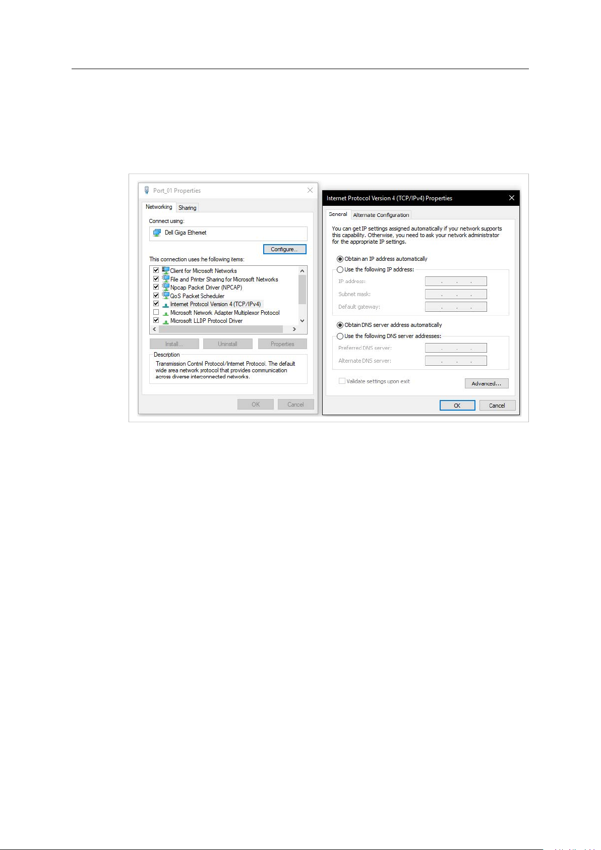
The ethernet port on your computer that is connected to the switch must be configured to get IP
address settings automatically.
Procedure
Fig. 19
To change the IP address settings of the ethernet port:
1. Navigate to the Control Panel and click Network Connections.
2. Right-click the network connected to the switch and click Properties.
3. Click Internet Protocal Verion 4 (TCP/IPv4).
4. Verify that the Obtain an IP address automatically and Obtain DNS server address
automatically radio buttons are selected.
5. Click OK.
Result
→ Now the Wireless Bolt IoT can generate IP addresses to the IO-Link master.
Anybus®Wireless Bolt IoT
™
SCM-1202-174 1.0 en-US
Page 17

Publish Data From IO-Link 15 (20)
7 Publish Data From IO-Link
HTTP/JSON-requests are used to fetch and write data to the IO-Link master and devices
connected to the ports on the master.
To publish data from the IO-Link master, a subscribe request must be sent to the IO-Link master
via a HTTP/JSON-request.
Before sending subscribe requests the timer must be set on the IO-Link master.
The timer controls the cycle time of when data is pushed on the MQTT publish channel.
Before You Begin
The most efficient way is to send data from the IO-Link master when data changes.
The approach used in this application note was the best solution at the time it was written.
Procedure
To set the timer:
1. Visit curl.haxx.se/download.html and download curl.
2. When the curl download is finished, open a command prompt on your computer.
3. Write the code from Example 1 and Example 2.
– "adr": "/timer[1]/interval/setdata"
specifies which timer to use, timer[1] or timer[2] .
– Set the timer[1] to a value between 500 ms and 2147483647 ms.
Example, the timer is set to 500 ms: "newvalue": 500
– http://192.168.0.144 is the IP address of the IO-Link master.
Example 1: Request
{
"code": "request",
"cid": 4712,
"adr": "/timer[1]/interval/setdata",
"data": {
"newvalue": 500
}
}
Example 2: Request in curl
curl --header "Content-Type: application/json"
--request POST
--data '{
"code": "request",
"cid": 4712,
"adr": "/timer[1]/interval/setdata",
"data": {
"newvalue": 500
}
} '
http://192.168.0.144
Anybus®Wireless Bolt IoT
™
SCM-1202-174 1.0 en-US
Page 18

Publish Data From IO-Link 16 (20)
In Windows, there can be issues with single and double quotes, write the following:
curl --header "Content-Type: application/json"
--request POST
--data "{
\"code\": \"request\",
\"cid\": 4712,
\"adr\": \"/timer[1]/interval/setdata\",
\"data\": {
\"newvalue\":500
}
}"
http://192.168.0.144
4. Send the request.
→ If the request is successful, the response is according to Example 3: Response.
Example 3: Response
{
"cid": 4712,
"code": 200
}
5. Write the code from Example 4 and Example 5.
– The public Mosquitto MQTT broker: https://test.mosquitto.org/.
– The Mosquitto brokers IP address: 5.196.95.208
– Port: 1883
– Topic: test.
Example 4: Subscribe Request
{
"code": "request",
"cid": 4712,
"adr": "timer[1]/counter/datachanged/subscribe",
"data": {
"callback": "mqtt://5.196.95.208:1883/test",
"datatosend": [
"iolinkmaster/port[1]/iolinkdevice/pdin"
]
}
}
Example 5: Subscribe Request in curl
curl --header "Content-Type: application/json"
--request POST
--data ' {
"code": "request",
"cid": 4712,
"adr": "timer[1]/counter/datachanged/subscribe",
"data": {
"callback": "mqtt://5.196.95.208:1883/test",
"datatosend": [
"iolinkmaster/port[1]/iolinkdevice/pdin"
]
}
} '
http://192.168.0.144
Anybus®Wireless Bolt IoT
™
SCM-1202-174 1.0 en-US
Page 19

Publish Data From IO-Link 17 (20)
In Windows, there can be issues with single and double quotes, write the following:
curl --header "Content-Type: application/json"
--request POST
--data "{
\"code\": \"request\",
\"cid\": 4712,
\"adr\": \"timer[1]/counter/datachanged/subscribe\",
\"data\":{\"callback\": \"mqtt://5.196.95.208:1883/test\",
\"datatosend\": [
\"iolinkmaster/port[1]/iolinkdevice/pdin\"
]
}
}"
http://192.168.0.144
6. Send subscribe request to the IO-Link master.
→ If the request is successful, the response is according to Example 6: Response:
Example 6: Response
{
"cid": 4712,
"code": 200
}
To unsubscribe:
When unsubscribing, always use the same cid that was used for subscribing to the event.
7. Write the code according to Example 7: Unsubscribe Request.
Example 7: Unsubscribe Request
{
"code": "request",
"cid": 4712,
"adr": "timer[1]/counter/datachanged/unsubscribe",
"data": {
"callback": "mqtt://5.196.95.208:1883/test",
"datatosend": [
"iolinkmaster/port[1]/iolinkdevice/pdin"
]
}
}
Anybus®Wireless Bolt IoT
™
SCM-1202-174 1.0 en-US
Page 20
Verify Communication 18 (20)
8 Verify Communication
To verify that the IO-Link master is sending data from the ifm pushbutton to the Mosquitto
broker, there must be an additional device connected that subscribes to the same topic that
the IO-Link master is publishing to.
As an additional device, we use an MQTT Client.
The devices subscribe to the topic: test
Fig. 20
Procedure
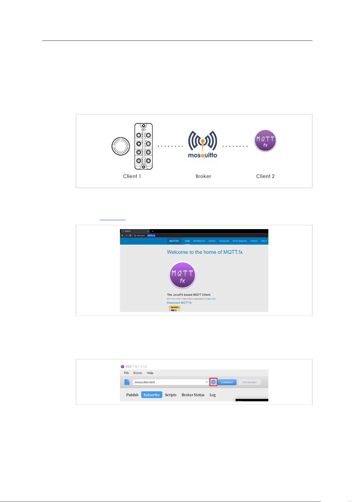
1. Visit mqttfx.org and download the JavaFX based MQTT Client installation file MQTT.fx.
Fig. 21
2. Install the JavaFX based MQTT Client on your computer.
3. Start the MQTT Client.
4. Open the MQTT Broker Profile Settings.
Anybus
Fig. 22
®
Wireless Bolt IoT
™
SCM-1202-174 1.0 en-US
Page 21
Verify Communication 19 (20)
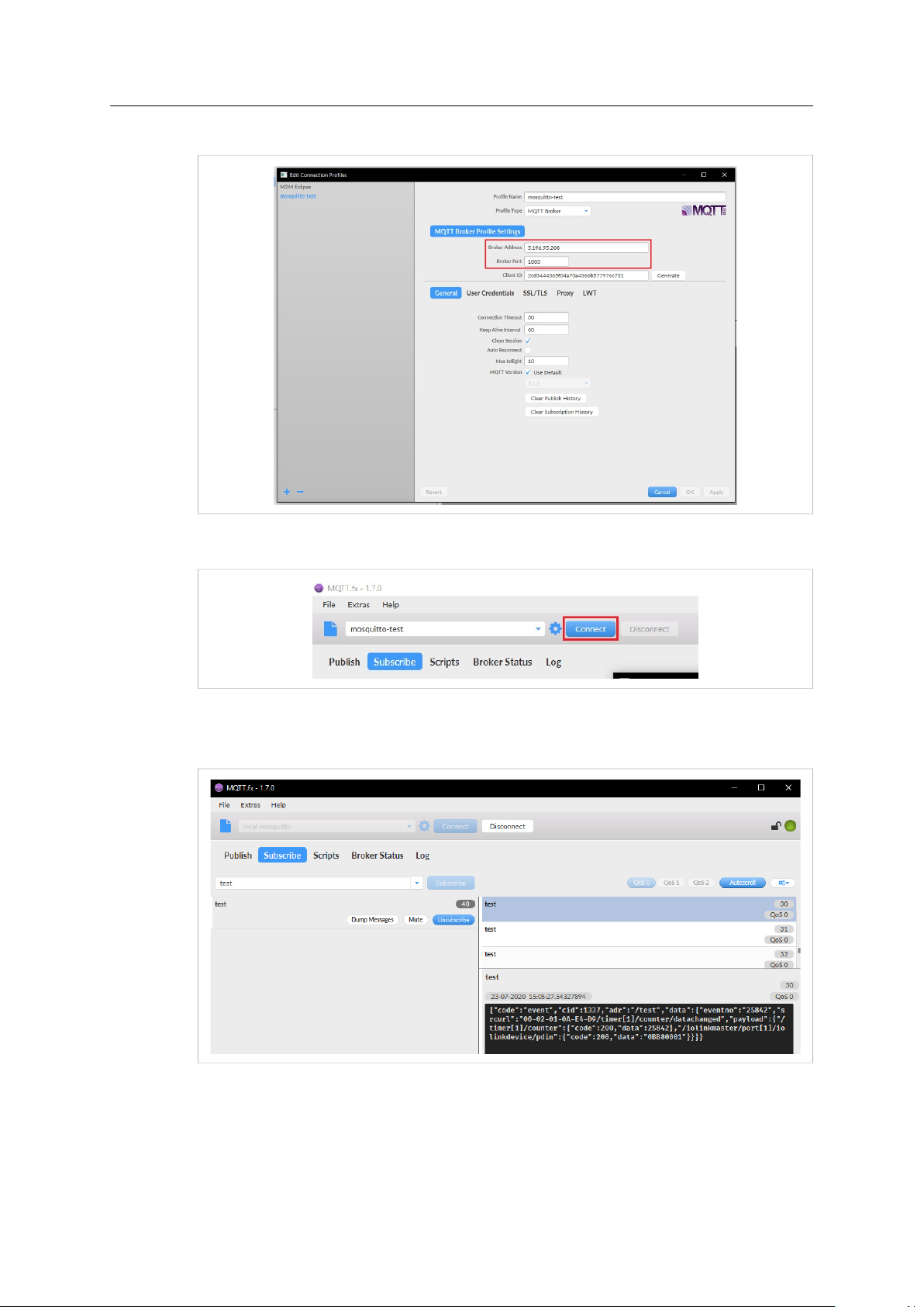
5. Enter the Brokers IP address and the Broker Port and then click OK.
Fig. 23
6. Click Connect.
Fig. 24
Result
Fig. 25
→ The indicator at the top right of the page, turns green.
→ The data from the ifm pushbutton connected to the IO-Link master appear in the bottom
Anybus®Wireless Bolt IoT
right corner.
™
SCM-1202-174 1.0 en-US
Page 22

last page
© 2021 HMS Industrial Networks
Box 4126
300 04 Halmstad, Sweden
info@hms.se SCM-1202-174 1.0 en-US / 2021-01-28 / 21368
 Loading...