

Page 1

+$/067$'&+,&$*2.$5/658+(72.<2%(,-,1*0,/$1208/+286(&29(175<381(&23(1+$*(1
HMS Industrial Networks
Mailing address: Box 4126, 300 04 Halmstad, Sweden
Visiting address: Stationsgatan 37, Halmstad, Sweden
Connecting Devices
TM
E-mail: info@hms-networks.com
Web: www.anybus.com
User Manual
Anybus® Modbus-TCP/RTU Gateway
AB7702
Doc.Id. HMSI-168-77
Rev. 2.03
Page 2

Table of Contents
Preface About This Document
How To Use This Document............................................................................................................. P-1
Important User Information............................................................................................................... P-1
Document History ...............................................................................................................................P-2
Conventions & Terminology .............................................................................................................. P-2
Sales and Support ................................................................................................................................. P-3
Chapter 1 About the Anybus® Modbus TCP/RTU Gateway
General Information .............................................................................................................................1-1
Mounting.................................................................................................................................................1-2
Connectors .............................................................................................................................................1-3
Modbus/RTU Interface, RS-232.................................................................................................1-3
Modbus/RTU Interface, RS-485 and RS-232 ............................................................................1-3
Ethernet Interface..........................................................................................................................1-3
Power Supply Connection ..............................................................................................................1-3
Digital Inputs ...............................................................................................................................1-4
Indicators ................................................................................................................................................1-4
LED functionality ........................................................................................................................1-4
Table of Contents
Chapter 2 Configuration
Configure the IP address ......................................................................................................................2-1
About the Anybus IPConfig utility ...............................................................................................2-1
Installation....................................................................................................................................2-1
Scanning for connected devices.........................................................................................................2-1
Changing IP Settings.....................................................................................................................2-3
Configure the Gateway .........................................................................................................................2-3
Log in...........................................................................................................................................2-3
Network Settings ..........................................................................................................................2-5
Modbus Configuration...................................................................................................................2-6
Internal Registers...........................................................................................................................2-7
Password Settings..........................................................................................................................2-8
Status ...........................................................................................................................................2-9
Appendix A Specifications
Ethernet Connection ...........................................................................................................................A-1
Serial Interfaces.....................................................................................................................................A-1
Power Supply ........................................................................................................................................A-1
Environmental Specification ..............................................................................................................A-1
Cover Material.......................................................................................................................................A-1
Mounting Option .................................................................................................................................A-1
Certifications .........................................................................................................................................A-2
CE Certification ..........................................................................................................................A-2
UL Certification ..........................................................................................................................A-2
Page 3

Doc.Id. HMSI-168-77
About This Document
How To Use This Document
This document is intended to provide a good understanding of the functionality offered by the Anybus®
Modbus-TCP/RTU Gateway.
The reader of this document is expected to be familiar with industrial networking systems, and communication systems in general.
For more information, documentation etc., please visit the HMS web site, ‘www.anybus.com’.
Important User Information
The data and illustrations found in this document are not binding. We, HMS Industrial Networks AB,
reserve the right to modify our products in line with our policy of continuous product development. The
information in this document is subject to change without notice and should not be considered as a commitment by HMS Industrial Networks AB. HMS Industrial Networks AB assumes no responsibility for
any errors that may appear in this document.
Preface
There are many applications of this product. Those responsible for the use of this device must ensure
that all the necessary steps have been taken to verify that the application meets all performance and safety requirements including any applicable laws, regulations, codes, and standards.
Anybus® is a registered trademark of HMS Industrial Networks AB. All other trademarks are the property of their respective holders.
The examples and illustrations in this document are included solely for illustrative purposes. Because of
the many variables and requirements associated with any particular implementation, HMS Industrial
Networks cannot assume responsibility or liability for actual use based on these examples and illustrations.
Warning: This is a class A product. In a domestic environment this product may cause radio interfer-
ence in which case the user may be required to take adequate measures.
ESD Note: This product contains ESD (Electrostatic Discharge) sensitive parts that may be damaged
if ESD control procedures are not followed. Static control precautions are required when
handling the product. Failure to observe this may cause damage to the product.
Anybus® Modbus-TCP/RTU Gateway
Doc.Rev. 2.03
Page 4

Document History
Summary of Recent Changes (2.02 ... 2.03)
Change Page(s)
Changed maxed supply voltage level from 32 V to 28 V 1-3, A-1
Changed UL file number A-2
Revision List
Revision Date Author Chapter Description
.....1.13 In Microsoft Word
2.00 2009-10-09 KeL All New look
2.01 2011-05-13 KeL P, A Miinor updates
2.02 2012-03-12 KeL A Miinor update
2.03 2012-09-21 KaD 1, A Minor updates
About This Document P-2
Conventions & Terminology
The following conventions are used throughout this document:
• Numbered lists provide sequential steps
• Bulleted lists provide information, not procedural steps
• The terms ‘Anybus’, ‘gateway’ or ‘module’ refers to the Anybus® Modbus-TCP/RTU Gateway.
• The term ‘host’ refers to a host device on a TCP/IP network.
• Hexadecimal values are written in the format NNNNh, where NNNN is the hexadecimal value.
Anybus® Modbus-TCP/RTU Gateway
Doc.Rev. 2.03
Doc.Id. HMSI-168-77
Page 5

Sales and Support
Sales Support
HMS Sweden (Head Office)
E-mail: sales@hms-networks.com E-mail: support@hms-networks.com
Phone: +46 (0) 35 - 17 29 56 Phone: +46 (0) 35 - 17 29 20
Fax: +46 (0) 35 - 17 29 09 Fax: +46 (0) 35 - 17 29 09
Online: www.anybus.com Online: www.anybus.com
HMS North America
E-mail: us-sales@hms-networks.com E-mail: us-support@hms-networks.com
Phone: +1-312 - 829 - 0601 Phone: +1-312-829-0601
Toll Free: +1-888-8-Anybus Toll Free: +1-888-8-Anybus
Fax: +1-312-629-2869 Fax: +1-312-629-2869
Online: www.anybus.com Online: www.anybus.com
HMS Germany
E-mail: ge-sales@hms-networks.com E-mail: ge-support@hms-networks.com
Phone: +49 (0) 721-989777-000 Phone: +49 (0) 721-989777-000
Fax: +49 (0) 721-989777-010 Fax: +49 (0) 721-989777-010
Online: www.anybus.de Online: www.anybus.de
HMS Japan
E-mail: jp-sales@hms-networks.com E-mail: jp-support@hms-networks.com
Phone: +81 (0) 45-478-5340 Phone: +81 (0) 45-478-5340
Fax: +81 (0) 45-476-0315 Fax: +81 (0) 45-476-0315
Online: www.anybus.jp Online: www.anybus.jp
HMS China
E-mail: cn-sales@hms-networks.com E-mail: cn-support@hms-networks.com
Phone: +86 (0) 10-8532-3183 Phone: +86 (0) 10-8532-3023
Fax: +86 (0) 10-8532-3209 Fax: +86 (0) 10-8532-3209
Online: www.anybus.cn Online: www.anybus.cn
HMS Italy
E-mail: it-sales@hms-networks.com E-mail: it-support@hms-networks.com
Phone: +39 039 59662 27 Phone: +39 039 59662 27
Fax: +39 039 59662 31 Fax: +39 039 59662 31
Online: www.anybus.it Online: www.anybus.it
HMS France
E-mail: fr-sales@hms-networks.com E-mail: fr-support@hms-networks.com
Phone: +33 (0) 3 68 368 034 Phone: +33 (0) 3 68 368 033
Fax: +33 (0) 3 68 368 031 Fax: +33 (0) 3 68 368 031
Online: www.anybus.fr Online: www.anybus.fr
HMS UK & Eire
E-mail: uk-sales@hms-networks.com E-mail: support@hms-networks.com
Phone: +44 (0) 1926 405599 Phone: +46 (0) 35 - 17 29 20
Fax: +44 (0) 1926 405522 Fax: +46 (0) 35 - 17 29 09
Online: www.anybus.co.uk Online: www.anybus.com
HMS Denmark
E-mail: dk-sales@hms-networks.com E-mail: support@hms-networks.com
Phone: +45 (0) 35 38 29 00 Phone: +46 (0) 35 - 17 29 20
Fax: +46 (0) 35 17 29 09 Fax: +46 (0) 35 - 17 29 09
Online: www.anybus.com Online: www.anybus.com
HMS India
E-mail: in-sales@hms-networks.com E-mail: in-support@hms-networks.com
Phone: +91 (0) 20 40111201 Phone: +91 (0) 20 40111201
Fa x: +91 ( 0) 20 401111 05 Fax: + 91 (0 ) 20 4 0111105
Online: www.anybus.com Online: www.anybus.com
About This Document P-3
Anybus® Modbus-TCP/RTU Gateway
Doc.Rev. 2.03
Doc.Id. HMSI-168-77
Page 6
Doc.Id. HMSI-168-77
Chapter 1
About the Anybus® Modbus-TCP/RTU Gateway
General Information
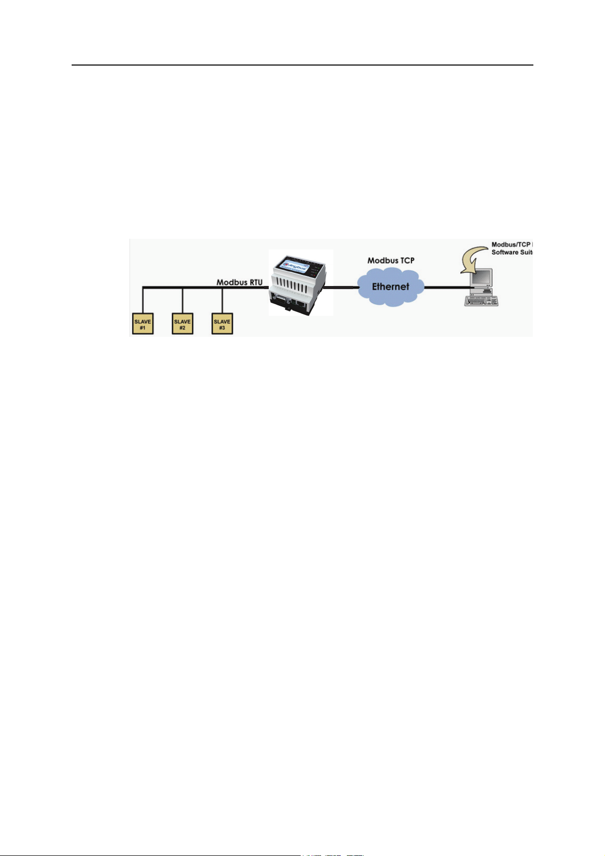
The Anybus® Modbus-TCP/RTU Gateway can be used to connect a Modbus/TCP master to one or
several Modbus/RTU slaves. The transparent Modbus TCP/RTU gateway will act as a Modbus/TCP
slave on an Ethernet network, and transform the queries to the Serial Modbus network, and send back
the Modbus/RTU slave response to the Modbus/TCP master.
The Anybus Modbus Gateway supports RS-232 through a 9-pole DSUB or RS-485 through the screw
terminal block on the other side of the module. It supports 10/100Mbps Ethernet through a standard
Ethernet connector (RJ-45). It can be configured via a web-interface or by using the Anybys IPConfig
utility. It also contains a Flash memory for easy software updates.
Anybus® Modbus-TCP/RTU Gateway
Doc.Rev. 2.03
Page 7

Mounting
A - Snap on
B - Snap off
MAC ID
About the Anybus® Modbus-TCP/RTU Gateway 1-2
1. Snap the Anybus module on to the DIN-rail (as described in picture A above).
2. Connect the Ethernet cable to the RJ45 connector.
3. Connect the Modbus/RTU network to the DSUB connector (RS-232) or through the screw ter-
minal block (RS-485)
4. Connect the power supply and apply power
5. Now you can start using the Gateway. Use the “Anybus IPConfig Utility” to configure the IP
address and other network settings. See 2-1 “Configure the IP address” for further information.
Note: The default IP address of the Anybus module is 10.200.1.X, where X is the last digit in the MAC
ID (can be found on a label on the device).
Anybus® Modbus-TCP/RTU Gateway
Doc.Rev. 2.03
Doc.Id. HMSI-168-77
Page 8

Connectors
15
96
(male)
Serial interface
(DSUB-9, RS-232)
Ethernet interface
(RJ-45, 10/100Mbps)
Modbus/RTU Interface, RS-232
The 9-pole DSUB, male connector on the Anybus module
contains a fully equipped RS-232 interface. This port can be
used to connect to any equipment with an RS-232 interface.
Pin no Function
1 CD (Carrier Detect)
2 Rx (Receive)
3 Tx (Transmit)
4 DTR (DTE Ready)
5GND
6 DSR (DCE Ready)
7 RTS (Request To Send)
8 CTS (Clear to Send)
9 RI (Ring Indicator)
About the Anybus® Modbus-TCP/RTU Gateway 1-3
Modbus/RTU Interface, RS-485 and RS-232
The product carries a screw terminal block with 12 contacts. Five of these can be used to connect to any
equipment with an RS-485 interface.
Ethernet Interface
The Ethernet interface supports 10/100 Mbps, using a standard RJ-45 connector.
Power Supply Connection
The Anybus module can be powered by a 9 - 28 V AC/DC supply.
Anybus® Modbus-TCP/RTU Gateway
Doc.Rev. 2.03
Doc.Id. HMSI-168-77
Page 9
About the Anybus® Modbus-TCP/RTU Gateway 1-4
Digital Inputs
The digital inputs are opto-isolated, and can accept a 10-24 VDC signal for logic HIGH input. For logic
LOW the voltage should be in the range 0-2 VDC.
The status of the inputs can be read in the Gateway Internal Registers (if enabled). See 2-7 “Internal
Registers” for more information.
Pin no Description
13 RS-485, line B
14 RS-485, line A
15 Common
16 RS-232, Tx
17 RS-232, Rx
18 Not connected
19 Not connected
20 Digital In Common
21 Digital In 1
22 Digital In 2
23 Vin- (ground connection)
24 Vin+
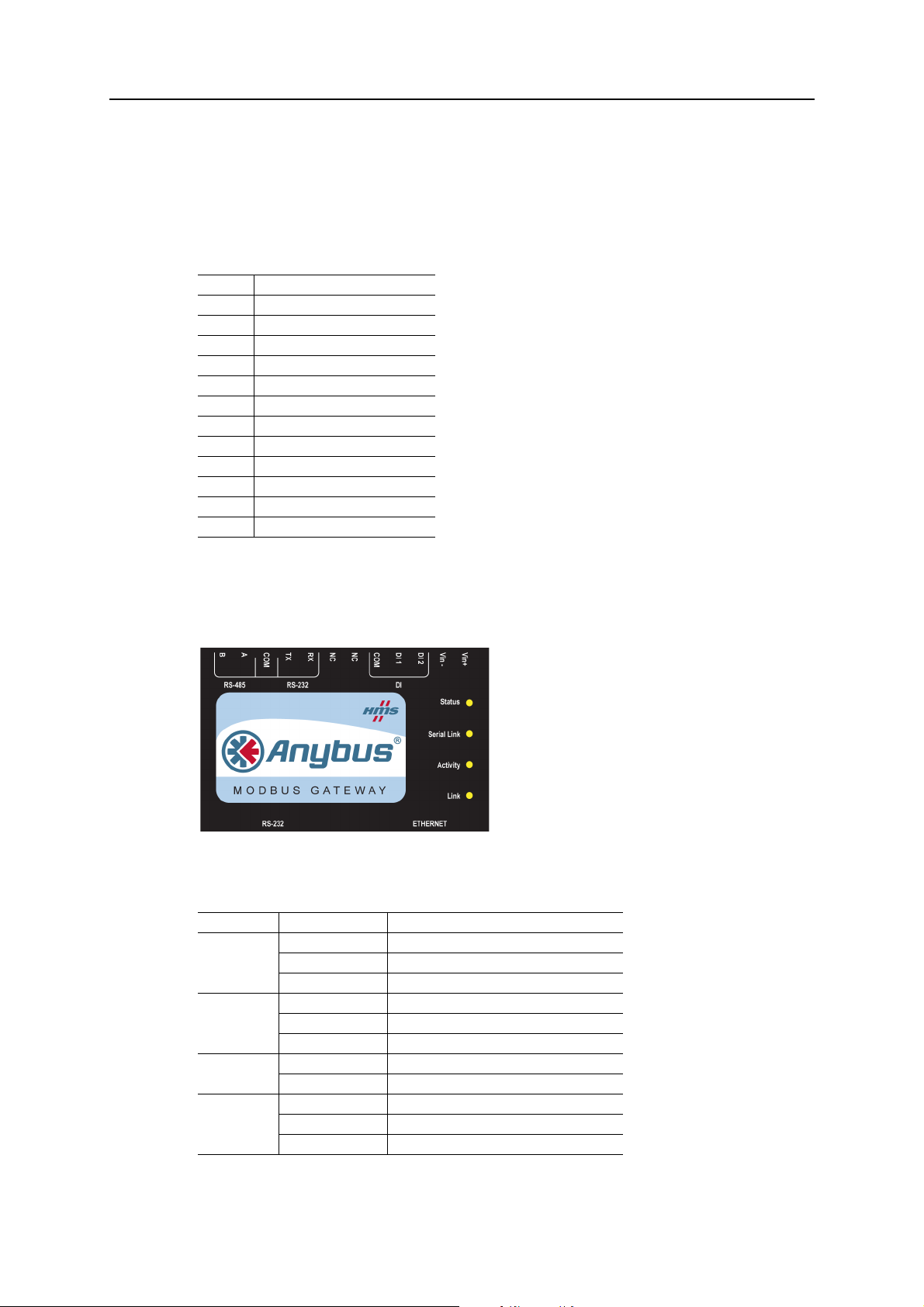
Indicators
LED functionality
Name Color Description
Status OFF Power off
Serial Link Flashing Green Serial Packet receive
Activity Flashing Green Ethernet Packet received
Link OFF No Ethernet Link detected
Green Module is running in normal mode
Orange Boot-up
Flashing Red Serial Packet transmit
Orange Boot-up
Flashing Red Ethernet Collision detected
Green Ethernet network detected, 10 Mbps
Orange Ethernet network detected, 100 Mbps
Anybus® Modbus-TCP/RTU Gateway
Doc.Rev. 2.03
Doc.Id. HMSI-168-77
Page 10

Doc.Id. HMSI-168-77
Configuration
Configure the IP address
About the Anybus IPConfig utility
The IPConfig utility is a PC-based configuration utility to set TCP/IP network settings in the Anybus
module. Anybus IPConfig scans the Ethernet network for connected Anybus devices and lets the user
set IP-address, net mask, gateway, DNS and host name for each unit.
Installation
System Requirements
• Pentium 133 MHz or higher
• 5 Mb of free space on the hard drive
• Win 95/98/ME/NT/2000/XP/Vista
• Network Interface Card (Ethernet)
Chapter 2
Installation Procedure
• Download the self-extracting installation package “Anybus IPConfig utility for module TCP/IP
configuration” from:
http://www.anybus.com/support/support.asp?PID=237&ProdType=Anybus%20X-gateway
• Run IPConfig
Scanning for connected devices
First ensure that you have connected the Anybus units you want to install on the same Ethernet network
as the PC is connected to. Use standard Ethernet cables, straight-through or crossover, depending on
how you connect to the device. See pictures below for details.
Anybus® Modbus-TCP/RTU Gateway
Doc.Rev. 2.03
Page 11

Configuration 2-2
Anybus
Modbus TCP/RTU
gateway
Anybus
Modbus TCP/RTU
gateway
Connecting the Anybus® Modbus-TCP/RTU Gateway to a hub or a switch
Connecting the Anybus® Modbus-TCP/RTU Gateway directly to a PC
When the Anybus IPConfig utility is started, it will scan the Ethernet network for Anybus devices. All
detected devices will be presented in a list in the main window. To force a new scan for devices, press
the “Scan” button.
Heading Description
IP IP address of the Anybus module
SN Subnet mask
GW Default gateway
DHCP Dynamically assigned IP address on/off
Version Application software version
Type Product type
MAC Ethernet MAC address
Anybus® Modbus-TCP/RTU Gateway
Doc.Rev. 2.03
Doc.Id. HMSI-168-77
Page 12

Configuration 2-3
Changing IP Settings
To change the IP settings of a detected device, double-click on the device you want to configure in the
list of devices.This will open a dialogue where you can enter the desired IP configuration. To obtain the
necessary information about IP address, Subnet mask etc. please contact your network administrator.
Note: Do not select the DHCP option if you don’t have a DHCP server available on the network.
Host name, Primary DNS and Secondary DNS are optional.
The default password for authentication of the new settings is “admin”. Pressing “Set” will cause the
Anybus module to reboot and the new settings will be enabled on restart. You can test the new settings
by opening a web browser and enter the IP you selected. If you selected DHCP and want to know what
IP your device has been assigned, you can do a new scan with the Anybus IPConfig utility to view the
new network configuration information.
Configure the Gateway
Log in
Open a web browser and enter the IP address you have set for the Anybus module with the Anybus
IPConfig utility:
http://10.10.12.204
Anybus® Modbus-TCP/RTU Gateway
Doc.Rev. 2.03
Doc.Id. HMSI-168-77
Page 13

Configuration 2-4
The login screen should appear:
To be able to configure the gateway you should enter “admin” in the user name box. This is the default
password and can be changed at a later stage.
If you have problems to log in and you are sure that your password is correct, make sure that Caps Lock
is not enabled on your keyboard.
Start Page
The start page shows the available options.
Anybus® Modbus-TCP/RTU Gateway
Doc.Rev. 2.03
Doc.Id. HMSI-168-77
Page 14

Configuration 2-5
Network Settings
Choosing “Network” will give the opportunity to view and change the TCP/IP settings in the module.
These settings are the same as the ones defined in Anybus IPConfig.
DHCP: Select this if you have a DHCP server on our network and you want the IP address to be assigned automatically by the server.
Note: Do not select the DHCP option if you don’t have a DHCP server available on the network.
Network Setting Comment
Host Name Enter the host name of your device (optional)
IP address IP address
Netmask Subnet mask
Gateway The default gateway
Primary DNS The primary Domain Name server (optional)
Secondary DNS The secondary Domain Name server (optional)
Anybus® Modbus-TCP/RTU Gateway
Doc.Rev. 2.03
Doc.Id. HMSI-168-77
Page 15

Modbus Configuration
Choosing “Config” will give the opportunity to configure Modus.
Configuration 2-6
Serial settings (Modbus RTU/
ASCII)
Comment
Transmission Mode RTU or ASCII
Slave Response Time out Default value 200ms
Physical Interface EIA-485 or EIA-232
Baud Rate 300, 600, 1200, 2400, 4800, 9600, 19200, 38400, 57600 or 115200 bps
Character Format Select number of stop bits and if parity should be enabled (odd or even)
Extra delay between messages Some nodes on the network may need extra time to finish handling one mes-
sage before they can receive the next message.
Character delimiter Specifies the time (in ms) that separates two messages. If set to 0 (zero), the
gateway will use the standard Modbus delimiter of 3.5 characters (the actual
number of ms will be calculated automatically based on the currently used
communication settings).
Ethernet settings
(Modbus TCP)
Comment
Port Number Which port to use for Modbus TCP communication. Default: 502
Gateway Registers The address offset to the gateway internal registers (if enabled). See page 2-7 “Internal Regis-
ters” for details.
Server Idle Time out Idle time out in seconds for the Modbus/TCP connection. If the gateway doesn’t receive any
Modbus/TCP query within this time the connection sill be closed. Default: 60 s.
IP Authentication Defines the IP-number of the device that is allowed to connect to the gateway.
Note: To ensure that the Modbus master can communicate with all slaves present on the bus, do not
assign the same address to more than one Modbus device.
Anybus® Modbus-TCP/RTU Gateway
Doc.Rev. 2.03
Doc.Id. HMSI-168-77
Page 16

Configuration 2-7
Internal Registers
If Gateway Registers are enabled, queries sent to those addresses will not be forwarded to the Serial
Modbus/RTU network, but handled by the gateway.
Register Name Values Options Comment
1 Digital input 1 status 0 or 1 Read only
2 Digital input 2 status 0 or 1 Read only
3 Number of active connec-
tions MB/TCP
4 Number of active internal
connections
Serial status (Modbus/TCP)
5 Valid responses 0 - 65535 Can be cleared
6 Serial time outs 0 - 65535 Can be cleared
7 CRC errors 0 - 65535 Can be cleared
8 Input Buffer overruns 0 - 65535 Can be cleared
9 Frame errors 0 - 65535 Can be cleared
10 Exceptions responses 0 - 65535 Can be cleared
Serial status (buffered messages)
11 Valid responses 0 - 65535 Can be cleared
12 Serial time outs 0 - 65535 Can be cleared
13 CRC errors 0 - 65535 Can be cleared
14 Input Buffer overruns 0 - 65535 Can be cleared
15 Frame errors 0 - 65535 Can be cleared
16 Exceptions responses 0 - 65535 Can be cleared
Serial status (internal requests and web pages)
17 Valid responses 0 - 65535 Can be cleared
18 Serial time outs 0 - 65535 Can be cleared
19 CRC errors 0 - 65535 Can be cleared
20 Input Buffer overruns 0 - 65535 Can be cleared
21 Frame errors 0 - 65535 Can be cleared
22 Exceptions responses 0 - 65535 Can be cleared
Configuration registers
23 Modbus/TCP Port 1 - 65535 Default: 502
24 Gateway Modbus address -1 - 255
25 Modbus/TCP idle time out 0 - 65535 (seconds) Default: 60 seconds
1 - 65535 Enabled
26 Baud rate 2400 2400 bps
27 Parity 0 - 2
0 - 10 Read only
0 - 10 Read only
-1 Disabled Default
0 - 255 Enabled
0Disabled
4800 4800 bps
9600 9600 bps Default
19200 19200 bps
38400 38400 bps
57600 57600 bps
115200 115200 bps
0 No parity Default
1 Even parity
2 Odd parity
Anybus® Modbus-TCP/RTU Gateway
Doc.Rev. 2.03
Doc.Id. HMSI-168-77
Page 17

Register Name Values Options Comment
28 Number of stop bits 1 - 2 Default: 1 stop bit
29 Slave time out time 25 - 65535 ms Default: 1000 ms
30 Physical interface 0 - 2
0 EIA-485
Default
(Screw terminal block)
1 EIA-232
(DSUB)
2 EIA-232
(Screw terminal block)
Authentication
31 Valid IP address 1 0 - 255 First byte of IP address
0 Disabled IP address authentication disabled
1 - 255 Enabled
32 Valid IP address 2 0 - 255 Enabled Second byte of IP address
33 Valid IP address 3 0 - 255 Enabled Third byte of IP address
34 Valid IP address 4 0 - 255 Enabled Fourth byte of IP address
35 Mask for Valid IP address 1 0 - 255 Enabled First byte of mask
36 Mask for Valid IP address 2 0 - 255 Enabled Second byte of mask
37 Mask for Valid IP address 3 0 - 255 Enabled Third byte of mask
38 Mask for Valid IP address 4 0 - 255 Enabled Fourth byte of mask
Configuration 2-8
Valid commands:
Command Name
3 Read Holding Registers
6 Preset Single Register
16 Preset Multiple Registers
Password Settings
Choosing “Admin” will allow you to change the administrator password for the device.
Anybus® Modbus-TCP/RTU Gateway
Doc.Rev. 2.03
Doc.Id. HMSI-168-77
Page 18

Status
The following status information is available on the Status web page:
Configuration 2-9
Info Description
Number of connections Number of masters that are connected to the module
Valid Responses Counts valid responses from the Modbus/RTU slaves
Serial Time outs Number of Modbus/RTU slave time outs
CRC Errors Number of CRC errors on incoming Modbus/RTU responses
Buffer Overruns Number of input buffer overruns (if an incoming Modbus/RTU response is bigger than 300
bytes, it will cause the input buffer to overflow).
Exception Responses Number of exception responses from the connected Modbus/RTU slaves
Anybus® Modbus-TCP/RTU Gateway
Doc.Rev. 2.03
Doc.Id. HMSI-168-77
Page 19

Doc.Id. HMSI-168-77
Appendix A
Specifications
Ethernet Connection
10BASE-T or 100BASE-TX (IEEE 802.3). RJ45 connector.
Serial Interfaces
EIA-232 with full modem control (RTS, CTS, DCD, DTR, DSR, RI), 300-115200 bps, 9-pole DSUB
connector
EIA-485, 300-115200 bps, connection through screw terminal block
Power Supply
9 - 28 VAC/DC
70 mA@24 VDC (1.7 W).
Environmental Specification
Operating temp: - 40 - 65 °C
Storage temperature: - 40 - 85 °C
Humidity range: 5 - 93%, non-condensing
Cover Material
Grey plastic, LEXAN 940, self-extinguishing acc. to UL94-V0
Mounting Option
DIN rail (EN 50022)
Anybus® Modbus TCP/RTU Gateway
Doc.Rev. 2.03
Page 20

Certifications
CE Certification
EN 50081-2:1993
EN 1000-6-2:1999
UL Certification
The module is UL and cUL certified according to UL file number E214207.
For more information see www.anybus.com.
Specifications A-2
Anybus® Modbus TCP/RTU Gateway
Doc.Rev. 2.03
Doc.Id. HMSI-168-77
 Loading...