

Page 1

HMS Industrial Networks
Mailing address: Box 4126, 300 04 Halmstad, Sweden
Visiting address: Stationsgatan 37, Halmstad, Sweden
E-mail: info@hms-networks.com
Web: www.anybus.com
User Manual
Anybus® M-Bus to Modbus-TCP Gateway
Doc: HMSI-27-300
Rev. 1.10
Page 2

Table of Contents
About This Document
Related Documents ..................................................................................................................................1
Document History ...................................................................................................................................1
Conventions & Terminology .................................................................................................................. 1
Notes and warnings.......................................................................................................................... 1
Font conventions............................................................................................................................... 1
Glossary........................................................................................................................................... 2
Support....................................................................................................................................................... 2
Intellectual Property Rights............................................................................................................... 1
Trademark Acknowledgements......................................................................................................... 1
General Information
Introduction .............................................................................................................................................. 2
Description ................................................................................................................................................3
Connections...................................................................................................................................... 3
Table of Contents
Installation
Startup ........................................................................................................................................................ 4
Network configuration ............................................................................................................................ 4
CHIPtool ........................................................................................................................................ 5
Configuration
The web interface ..................................................................................................................................... 7
General tab...................................................................................................................................... 8
Meter tab......................................................................................................................................... 9
Configuration tab ........................................................................................................................... 12
Server tab.......................................................................................................................................14
Security tab .................................................................................................................................... 14
User tab......................................................................................................................................... 15
Service tab...................................................................................................................................... 17
Print page ......................................................................................................................................17
Modbus TCP specification
Function codes........................................................................................................................................18
Data format ............................................................................................................................................. 19
Dummy data.................................................................................................................................. 19
Acquiring and processing meter data
Meter configuration................................................................................................................................20
Scanning for meters......................................................................................................................... 20
Adding meters manually................................................................................................................. 21
Meter data format ................................................................................................................................... 22
Predefined Media ID Values ......................................................................................................... 22
Predefined measurement value types................................................................................................. 23
Predefined units ............................................................................................................................. 25
Modbus register layout.................................................................................................................... 26
Anybus M-Bus to Modbus-TCP Gateway User Manual Doc: HMSI-27-300, Rev: 1.10
Page 3

Troubleshooting
Hardware errors ......................................................................................................................................28
Gateway does not respond............................................................................................................... 28
Current consumption too high ......................................................................................................... 28
Network errors........................................................................................................................................29
Web interface and FTP server not accessible.................................................................................... 29
No network connection ................................................................................................................... 29
No write access to the web interface ................................................................................................. 30
Web session is unexpectedly terminated........................................................................................... 30
FTP login failure ........................................................................................................................... 30
Meter reading errors ............................................................................................................................... 31
No meters are detected .................................................................................................................... 31
Some meters are not detected............................................................................................................ 31
Meters are detected but have no data............................................................................................... 32
Scanning takes too long .................................................................................................................. 32
Gateway restarts occasionally during scan........................................................................................ 32
Webserver capacity error message..................................................................................................... 33
Meter data transmit error ......................................................................................................................33
Meter data not transmitted via Modbus.......................................................................................... 33
1-2
Advanced features
Software update ......................................................................................................................................34
Updating the operating system (RTOS) .......................................................................................... 35
Updating application software (firmware)........................................................................................ 36
Telnet connection................................................................................................................................... 37
FTP connection ......................................................................................................................................37
Configuration files ..................................................................................................................................38
System configuration file.................................................................................................................. 38
Meter configuration file ................................................................................................................... 41
Technical Specifications
General..................................................................................................................................................... 42
Dimensions and weight................................................................................................................... 42
Installation..................................................................................................................................... 42
Customs declaration........................................................................................................................ 42
Electrical ..................................................................................................................................................43
Power supply ..................................................................................................................................43
Meter interfaces .............................................................................................................................. 43
Communication interfaces ............................................................................................................... 43
Galvanic isolation........................................................................................................................... 43
Processing unit................................................................................................................................43
Anybus M-Bus to Modbus-TCP Gateway User Manual Doc: HMSI-27-300, Rev: 1.10
Page 4
P. About This Document
For more information, related documentation, etc., please visit the HMS website www.anybus.com.
P.1 Related Documents
Document Author
- -
P.2 Document History
Revision List
Revision Date Author(s) Chapter(s) Description
1.00 2015-02-26 ThN All First official release
1.10 2016-04-08 ThN 1, 6, A Added model with max 80 loads
Preface
P.3 Conventions & Terminology
The following conventions are used throughout this manual:
1. Numbered lists provide sequential steps.
• Bulleted lists provide information, not procedure steps.
P.3.1 Notes and warnings
This indicates additional important information.
This indicates important instructions that must be followed to avoid
equipment failure or damage.
P.3.2 Font conventions
Reboot system Menu command or button in graphical user interface.
MBUS_MAXRETRY Parameter entry in a source file.
Anybus M-Bus to Modbus-TCP Gateway User Manual Doc: HMSI-27-300, Rev: 1.10
Page 5

P.3.3 Glossary
Abbreviation Explanation
CSV Character-Separated Values
DNS Domain Name System
DI Digital Input
DO Digital Output
DIN Deutsches Institut für Normung, German standardization body
DLDE Direct Local Data Exchange (EN 62056-21, IEC 1107)
DLDERS DLDE communication via RS-232 or RS-485
DLMS Gateway Language Message Specification
I/O In- / Output
ESD ElectroStatic Discharge
FNN Forum Netztechnik/Netzbetrieb
Forum for network technology / network operation (committee of VDE)
FTP File-Transfer Protocol
GPRS General Packet Radio Service
GSM Global System for Mobile Communications
HTTP Hypertext Transfer Protocol
ID Identification, Identifier
IP Internet Protocol or. IP address
LED Light-Emitting Diode
M-Bus Meter-Bus (EN 13757-2/3)
MAC Medium Access Control or MAC address
MUC Multi Utility Communication, MUC-Controller
OEM Original Equipment Manufacturer
PEM Privacy Enhanced Mail
PPP Point-to-Point Protocol
PPPoE Point-to-Point Protocol over Ethernet
RFC Requests For Comments
RSSI Received Signal Strength Indicator
RTC Real Time Clock
RTOS Real Time Operating System
S0 S0 interface (pulse interface, EN 62053-31)
SIM Subscriber Identity Module
SML Smart Message Language
SMTP Simple Mail Transfer Protocol
SNTP Simple Network Time Protocol
TCP Transmission Control Protocol
TLS Transport Layer Security
UTC Coordinated Universal Time
VDE Verband der Elektrotechnik Elektronik Informationstechnik e.V.
(association for electrical, electronic & information technologies)
WAN Wide Area Network
wM-Bus Wireless Meter-Bus (EN 13757-3/4)
XML eXtensible Markup Language
About This Document 2
P.4 Support
For general contact information and support, please refer to the HMS website www.anybus.com.
Anybus M-Bus to Modbus-TCP Gateway User Manual Doc: HMSI-27-300, Rev: 1.10
Page 6

Important User Information
This document contains a general introduction as well as a description of the technical features provided by the
Anybus M-Bus to Modbus-TCP Gateway, including the PC-based configuration software.The document only describes the features that are specific to this product.
The reader of this document is expected to be familiar with PLC technology and communication systems in general. The reader is also expected to be familiar with the Microsoft® Windows® operating system.
Liability
Every care has been taken in the preparation of this manual. Please inform HMS Industrial Networks AB of any
inaccuracies or omissions. The data and illustrations found in this document are not binding. We, HMS Industrial
Networks AB, reserve the right to modify our products in line with our policy of continuous product development.
The information in this document is subject to change without notice and should not be considered as a commitment by HMS Industrial Networks AB. HMS Industrial Networks AB assumes no responsibility for any errors that
may appear in this document.
There are many applications of this product. Those responsible for the use of this gateway must ensure that all
the necessary steps have been taken to verify that the applications meet all performance and safety requirements
including any applicable laws, regulations, codes, and standards.
HMS Industrial Networks AB will under no circumstances assume liability or responsibility for any problems that
may arise as a result from the use of undocumented features, timing, or functional side effects found outside the
documented scope of this product. The effects caused by any direct or indirect use of such aspects of the product
are undefined, and may include e.g. compatibility issues and stability issues.
The examples and illustrations in this document are included solely for illustrative purposes. Because of the many
variables and requirements associated with any particular implementation, HMS Industrial Networks AB cannot
assume responsibility for actual use based on these examples and illustrations.
Intellectual Property Rights
HMS Industrial Networks AB has intellectual property rights relating to technology embodied in the product described in this document. These intellectual property rights may include patents and pending patent applications
in the US and other countries.
Trademark Acknowledgements
Anybus ® is a registered trademark of HMS Industrial Networks AB. All other trademarks are the property of their
respective holders.
Warning: This is a class A product. in a domestic environment this product may cause radio interference in
which case the user may be required to take adequate measures.
ESD Note: This product contains ESD (Electrostatic Discharge) sensitive parts that may be damaged if ESD
control procedures are not followed. Static control precautions are required when handling the product. Failure to observe this may cause damage to the product.
Anybus M-Bus to Modbus-TCP Gateway User Manual
Copyright© HMS Industrial Networks AB
Doc: HMSI-27-300
Anybus M-Bus to Modbus-TCP Gateway User Manual Doc: HMSI-27-300, Rev: 1.10
Page 7

1. General Information
1.1 Introduction
The M-Bus (Meter-Bus) is defined in the standard EN 13757, and is an established and well known interface for automated meter reading. Ease of installation (simple two-wire system with powering by the
bus) and robustness are the most important features. M-Bus has its own physical layer and protocol, so
a translation is necessary to connect it to other systems.
In the field of automation, Modbus TCP is one of the most common communication standards. The
Anybus M-Bus to Modbus-TCP Gateway allows the direct transmission of meter data to a control system (PLC, DDC etc.) using Modbus TCP.
The Anybus M-Bus to Modbus-TCP Gateway supports operating up to either 20 or 80 meters (standard
loads) on the M-Bus depending on the selected gateway version. A powerful protocol stack is implemented. It handles the complete data handling on the Anybus M-Bus to Modbus-TCP Gateway compliant to the standard. All available meters on the market can be read out and processed without further
manual configuration. The meter data is available for other systems without effort.
The Anybus M-Bus to Modbus-TCP Gateway serves as a Modbus TCP slave gateway (Modbus TCP
server) via its Ethernet port. The PLC as a Modbus master (Modbus TCP client) can access meter data
via a network connection. The data is available in different Modbus registers.
Chapter 1
The Anybus M-Bus to Modbus-TCP Gateway reads out the meters autonomously, which is why an initial configuration of the gateway is necessary. A built-in web interface simplifies this process. Via this
web interface all the functionality of the gateway is available to the user. In addition to basic system configuration values can be selected to be available via Modbus, M-Bus scans can be performed, and the
current data is reported. Remote control or remote service is also facilitated through the web interface.
The Anybus M-Bus to Modbus-TCP Gateway comes in a 2U enclosure and is intended for standard
35 mm DIN rail mounting.
Anybus M-Bus to Modbus-TCP Gateway User Manual Doc: HMSI-27-300, Rev: 1.10
Page 8

1.2 Description
24VDC
GND
MBUS+
MBUS-
MBUS+
MBUS-
1.2.1 Connections
The Anybus M-Bus to Modbus-TCP Gateway has the following connections:
General Information 3
Connector Pin assignment Note
Power supply 24 VDC: positive power supply
GND: negative power supply
M-Bus connectors MBUS+: positive bus line (2x)
MBUS-: negative bus line (2x)
Ethernet interface 1: TX+
2: TX−
3: RX+
4: Termination
5: Termination
6: RX−
7: Termination
8: Termination
24 VDC (±5%), Screw clamp
Cross sectional area 2.5 mm²
Screw clamp
Cross sectional area 2.5 mm²
MBUS+ and MBUS- are shorted each
According to TIA-568A/B
Anybus M-Bus to Modbus-TCP Gateway User Manual Doc: HMSI-27-300, Rev: 1.10
Page 9

2. Installation
2.1 Startup
After connecting the supply voltage the gateway will boot up automatically.
The following calls are made on system startup:
• Configuration of the network interface (Ethernet) via DHCP or static configuration
• Providing a RAM drive as drive C:
• Obtaining the system time via SNTP
• Starting the main program
The main program provides the entire functionality including the web interface of the gateway.
2.2 Network configuration
The gateway is configured through the built-in web interface, see 3. Configuration.
Chapter 2
To be able to access the web interface, the IP address of the gateway must be in the same subnet (IP
address range) as your local network. If you are unsure about the configuration of your network, please
consult your network administrator.
Default network configuration of Anybus M-Bus to Modbus-TCP Gateway
Static IP address 192.168.1.101
Subnet mask 255.255.255.0
Gateway 192.168.1.254
If the default IP address of the gateway (192.168.1.101) is not within your subnet range, you can change
the IP address using CHIPtool, a free Windows®-based application which can be downloaded here
If the link above does not work, go to the main Beck IPC GmbH download web page
http://www.beck-ipc.com/en/download/index.asp
Changing the network configuration may restrict accessibility. If the
network parameters have been correctly set by an administrator you
should not change them.
and search for “CHIPtool”.
.
Anybus M-Bus to Modbus-TCP Gateway User Manual Doc: HMSI-27-300, Rev: 1.10
Page 10
2.2.1 CHIPtool
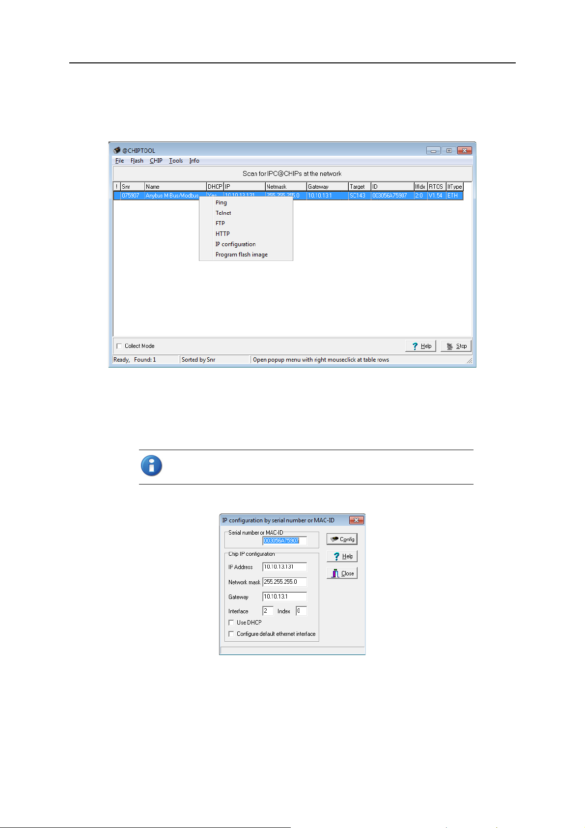
1. Download and install CHIPtool, then start it using the link in the Windows Start Menu.
The first window will show a list of all detected devices in the local network.
Installation 5
2. Right-click on the gateway that you wish to configure, then select
context menu.
3. If your network has a DHCP server, check
If your network does not have a DHCP server, change the
Gateway settings manually to match your network.
If Use DHCP is checked but the gateway is not able to obtain an IP address dynamically, it will choose a random IP address in the range 169.254.xxx.xxx.
4. Press
Config to save the IP configuration to the gateway.
Use DHCP for automatic configuration.
IP Address, Network mask and
IP configuration from the
Anybus M-Bus to Modbus-TCP Gateway User Manual Doc: HMSI-27-300, Rev: 1.10
Page 11
Installation 6
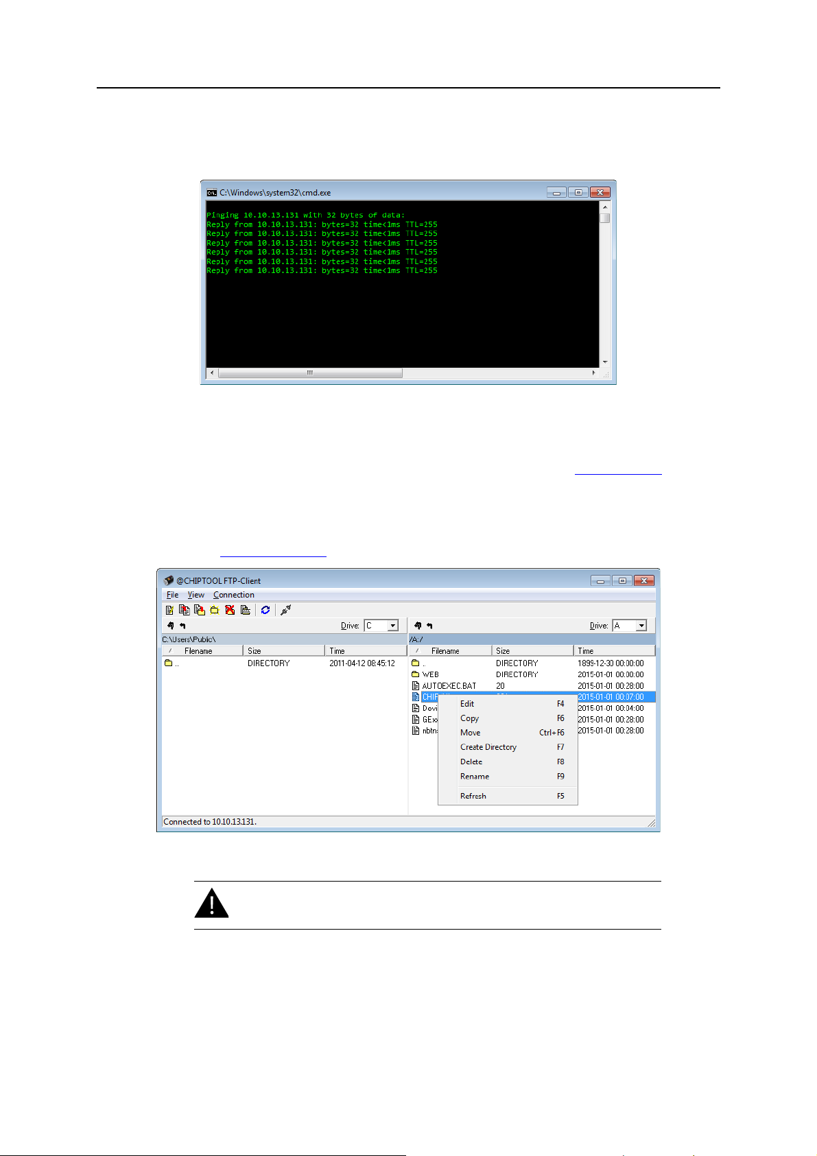
Connection test (ping)
The
Ping command in the CHIPtool context menu can be used for testing the connection. It will open
a Windows command line window and run a standard ping command.
File access (FTP)
The
FTP command in the CHIPtool context menu opens a built-in FTP client, allowing access to the
file system in the gateway. FTP access is restricted to certain users, see also 3.
Configuration.
After logging in, the FTP client will open a file manager window where the left half shows the file system
in your computer, and the right half the the file system in the gateway. Right-clicking on a file or folder
will open a context menu with file commands.
See also 7.3
FTP connection.
Changes to the files and file system should only be carried out by trained
personnel as it may restrict the functionality of the gateway.
Web access (HTTP)
The
HTTP command in the CHIPtool context menu will open the web interface of the gateway in the
default browser.
Anybus M-Bus to Modbus-TCP Gateway User Manual Doc: HMSI-27-300, Rev: 1.10
Page 12
3. Configuration
The Anybus M-Bus to Modbus-TCP Gateway is normally configured via the web interface, which gives
access to all gateway parameters, meter configuration and services. The gateway can also be configured
by uploading configuration files directly to the gateway via FTP, see 7.
Changes to the files and file system should only be carried out by trained
personnel as it may restrict the functionality of the gateway.
3.1 The web interface
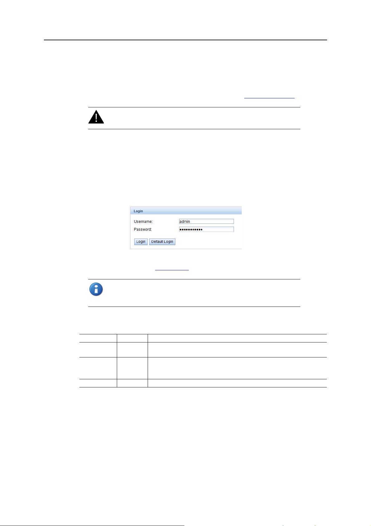
Auto login
The first time you access the web interface you will be automatically logged in with the default username
and password. You can also log in as the default user manually by clicking
screen. The default user only has read access.
Advanced features.
Default Login on the login
Chapter 3
If the default user has been disabled in the configuration, you need to enter a valid username and password and click
Default users and passwords
User Password Description
admin admin Administrator user with root access, allows full access to all services
web web Default user for the web interface. Allows write access to the web interface.
ftp ftp User for FTP access to the log directory (C:/log/)
Login. See also 3.1.6 User tab.
If you are logged in with write access you should always log out after finishing the
configuration, as only one user with write access can be logged in at a time. If
your session stays active, other users will not be able to log in with write access.
(HTTP, FTP, flash update, IP configuration).
If a user with this name and password exists, the web server will automatically log in
with these credentials when accessed.
Anybus M-Bus to Modbus-TCP Gateway User Manual Doc: HMSI-27-300, Rev: 1.10
Page 13
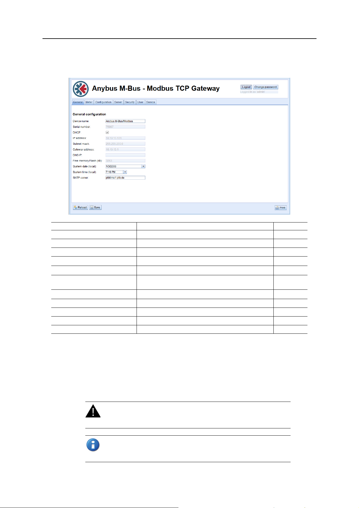
3.1.1 General tab
The General tab shows an overview of the current gateway configuration..
Configuration 8
Field Description Write access
Gateway name Name of the gateway (displayed in CHIPtool) Yes
Serial number Serial number of the gateway No
DHCP Enable automatic network configuration Yes
IP address
Subnet mask
Gateway address
DNS IP
Free Memory Flash (kB) Free storage space on internal memory of the controller No
System date (local) Current local system date Yes
System time (local) Current local system time Yes
SNTP Server Address of time server Yes
a. If DHCP is checked, the network parameter fields will be disabled
a
a
a
a
Reload discards the changes made on the page and reloads the currently active settings.
Save saves the changes and reinitializes the gateway.
IP address of gateway Yes
Subnet mask of gateway Yes
IP address of your local network gateway (not to be confused with
the Anybus M-Bus to Modbus-TCP Gateway)
IP address of DNS server Yes
Yes
If the network configuration is changed, the gateway will be available under the new IP address after you
click
Save. All established network connections to the gateway will be terminated and logged in users
will be logged out automatically.
Changing the network configuration may restrict accessibility. If the
network parameters have been correctly set by an administrator you
should not change them.
Date and time are processed internally as UTC time (without time zone shift).
The web browser will then convert the date and time according to the local time
zone of the computer.
Anybus M-Bus to Modbus-TCP Gateway User Manual Doc: HMSI-27-300, Rev: 1.10
Page 14
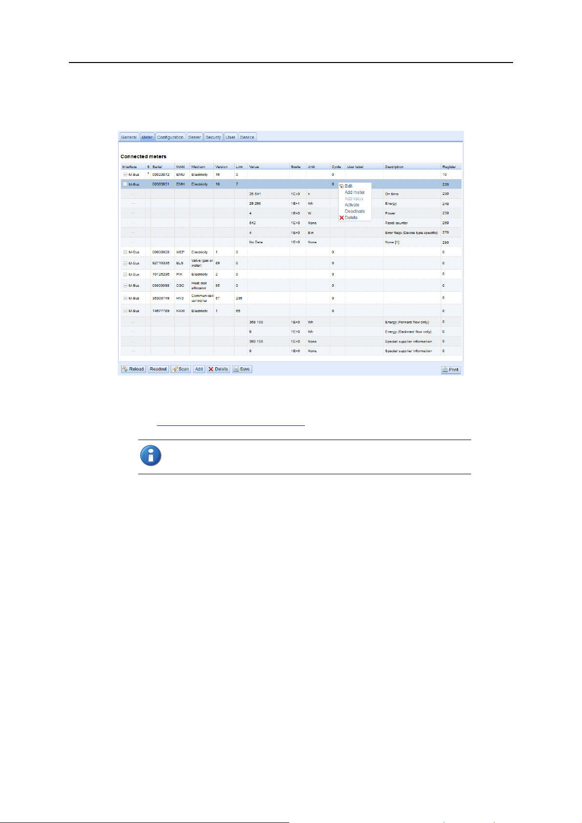
3.1.2 Meter tab
The Meter tab displays a list of connected meters and allows you to search, add and edit entries.
Configuration 9
The meter list is initially empty. After connecting one or several meters to the gateway, click
start populating the list. The scan is configured on the
See also 5.
The default configuration for each meter is applied immediately after scanning. Additional changes to
the configuration must be saved manually.
The list is additively expanded with each scan, and existing meters will not be deleted even if they are
not available anymore.
The meter configuration can be changed with the buttons in the bottom area of the page, or by rightclicking a meter entry. Meters entries and meter value entries can – within the limitations of the used
interface – be automatically searched, created, deleted or edited.
Meter entries and meter value entries can be selected with a single mouse click. Multiple selections are
possible by holding the SHIFT or CTRL keys.
When activating or deactivating a meter, its meter values are automatically enabled or disabled according
to the hierarchy. If a meter is inactive, it is activated by enabling one of its meter values.
Acquiring and processing meter data.
Scanning can take a long time, depending on the mode and number of connected
meters. The scan process cannot be interrupted.
Configuration tab.
Scan to
Anybus M-Bus to Modbus-TCP Gateway User Manual Doc: HMSI-27-300, Rev: 1.10
Page 15

Configuration 10
Meter tab fields
Field Description Write access
Interface Interface of meter (M-Bus) No
S Entry status – E indicates that value has been edited Yes
Serial Serial number of meter No
MAN Manufacturer of meter (abbreviation) No
Medium Medium of meter (see 5.2.1
Version Version number of meter No
Value Meter reading or measurement value No
Scale Scale factor (scientific notation) No
Unit Unit (see 5.2.1
Cycle Readout interval in seconds (entering 0 means using the general readout interval) Yes
User label User specific description of meter or value.
Included in export of CSV data, allows application specific mapping.
Description Description of meter value (see 5.2.1
Register Modbus register address, in steps of 10 (see 5.2.4
Active Activates the transfer of meter or meter value via Modbus TCP Yes
Predefined Media ID Values)No
Predefined Media ID Values)No
Yes
Predefined Media ID Values)No
Modbus register layout)Yes
The arrangement of data in the meter list corresponds to the order of the data in the M-Bus protocol.
The meaning of the values can thus be compared directly with the data sheet of the meter. It is also possible to assign the meter values to the raw data of the meter (see 3.1.3
Configuration tab).
Timestamps transmitted within the M-Bus protocol are automatically assigned to the other meter values
where possible. Therefore, some of these may not appear in the list.
The configuration parameter MUC_SHOWTIMESTAMPENTRIES offers the possibility to manually
enable the display of all time stamps (see 7.4.1
System configuration file).
If a scan or a change in the meter list is terminated with the error message “Webserver capacity exceeded”, see 6.3.6
Webserver capacity error message.
Meters that are not found during a scan, or that do not support an automated scan, can be added manually to the meter list using the button
See also 5.1.2 Adding meters manually
Add or the context menu entry Add meter.
.
Anybus M-Bus to Modbus-TCP Gateway User Manual Doc: HMSI-27-300, Rev: 1.10
Page 16

Editing meter and value entries
Configuration 11
Meter and value entries can be configured by right-clicking the entry and selecting
menu, or by double-clicking the entry. The fields in the Edit dialog correlate with the fields in the meter
list. Depending on the used interface some fields may be disabled for editing.
The readout interval in seconds can be set independently for each meter in the field
is entered the global readout interval is used, see 3.1.3
Each meter or value entry can be assigned a
consist of a maximumof 50 characters including spaces.
User label for application-specific use. The User label can
Configuration tab.
Edit in the context
Cycle. If no value
Valid characters in User Label:
Unvalid characters:
Modbus address allocation
The Modbus register address can be assigned or reset for a single meter or all meters via the context
menu choices
checked for duplicates. If duplicate addresses are detected an error message will be shown.
Buttons at bottom of page
Readout will update all values regardless of their normal readout interval. This momentary readout may
take some time to create depending on the number of meters that are connected. The normal readout
cycle is not affected by a momentary readout.
Delete will delete the selected entry in the meter list. Individual meter value entries can not be deleted.
Reload discards the changes made on the page and reloads the currently active settings.
Save saves the changes and reinitializes the gateway.
Allocate and Deallocate. When the configuration is saved, the Modbus addresses will be
A-Z, a-z , 0-9
! § $ % & / ( ) = ? + , . *
< > “ ”
Anybus M-Bus to Modbus-TCP Gateway User Manual Doc: HMSI-27-300, Rev: 1.10
Page 17

3.1.3 Configuration tab
The Configuration tab provides global meter settings.
Configuration 12
Reload discards the changes made on the page and reloads the currently active settings.
Save saves the changes and reinitializes the gateway.
Anybus M-Bus to Modbus-TCP Gateway User Manual Doc: HMSI-27-300, Rev: 1.10
Page 18

Configuration 13
Configuration tab fields
Field Description Write access
Readout interval (s) Standard readout cycle of meters (in seconds). Value might be overwritten for each
meter by parameter Cycle in tab Meter
Description mode Mode of displaying the meter value description on the website:
None: No display of description
Standard: Display of common value description
Extended: Extended display of value description (parameters will be displayed if they differ from 0):
Notation:Description [Memory No.] <Tariff> {min|max|error}
Example:Energy [2] <1> {max}
Extended with DIF/VIF: Extended display including DIF and VIF raw data
Notation:Description [Memory No.] <Tariff> {Value Type} # XX XX XX …
Example:Energy [2] <1> # 8C 11 04
Extended with raw data: Extended display including the raw data oft he complete meter
value entry.
Notation corresponds to Extended with DIF/VIF:
Example:Energy [2] <1> # 8C 11 04 96 47 06 00
DIF/VIF:
Display of DIF/VIF raw data
Raw data:
Displays the raw data oft he complete meter value entry
After changing this parameter a readout is needed to update the meter list and to display
the relevant data.
Maximum gateway count Limitation of the number of meters to scan. (0: no limitation).
Already configured meters are not limitated by this parameter.
Maximum value count Limitation of the number of meter value entries to read during a readout (0: no limitation).
Already configured meter value entries are not limitated by this parameter.
RAW log active Activates the raw data log. Yes
M-Bus mode M-Bus scan mode (secondary, reverse secondary or primary search) Yes
Primary start address First address for primary search Yes
Primary final address Last address for primary search Yes
Secondary address mask Search mask for secondary search, 8 numerical characters; „F“ defines a wildcard; miss-
ing characters will be filled up with leading zeros
M-Bus baud rate Baudrate for M-Bus communication (300-19200 baud) Yes
M-Bus timeout M-Bus timeout until reception of first data (in ms) Yes
M-Bus idle timeout M-Bus timeout until end of reception (in ms) Yes
M-Bus full timeout M-Bus timeout (complete) for reception of a whole data packet (in ms) Yes
M-Bus request mode Mode of the M-Bus readout (REQ_UD2):
Standard: Readout with REQ_UD2
Extended 1: Readout with Get-All-Data (DIF/VIF 7F 7E) and REQ_UD2
Extended 2: Readout with Get-All-Data (DIF 7F) and REQ_UD2
M-Bus reset mode Mode of the M-Bus Reset (before scan and readout):
None: no reset
Standard: Send SND_NKE to primary address of the meter or broadcast address when
using secondary adressing
Extended 1:
Send SND_NKE to primary address FD and SND_NKE to primary address of the meter
or broadcast address when using secondary addressing
Extended 2: Send SND_NKE and an Application Reset to primary address FD and a
SND_NKE to the primary address of the meter or to broadcast address when using sec-
ondary addressing.
M-Bus max. multipage Limits the count of multipage requests Yes
Ye s
Ye s
Ye s
Ye s
Ye s
Ye s
Ye s
Anybus M-Bus to Modbus-TCP Gateway User Manual Doc: HMSI-27-300, Rev: 1.10
Page 19

Configuration 14
3.1.4 Server tab
The Server tab provides settings for the Modbus TCP interface.
Field Description Write access
Modbus Mode Select Modbus TCP (normal mode) or dummy data (see 4.2.1
Modbus Port Port number to which the Modbus TCP client (master) should connect Yes
Reload discards the changes made on the page and reloads the currently active settings.
Dummy data)Yes
Save saves the changes and reinitializes the gateway.
3.1.5 Security tab
The Security tab allows enabling/disabling of FTP and Telnet access to the gateway.
Field Description Write access
FTP server active Enable/disable FTP access Yes
Telnet server active Enable/disable Telnet access Yes
Reload discards the changes made on the page and reloads the currently active settings.
Save saves the changes and reinitializes the gateway.
Anybus M-Bus to Modbus-TCP Gateway User Manual Doc: HMSI-27-300, Rev: 1.10
Page 20

Configuration 15
3.1.6 User tab
The User tab allows you to create and manage users and assign them specific access rights. The following users are pre-configured on delivery:
User Password Description
admin admin Administrator user with root access, allows full access to all services
(HTTP, FTP, flash update, IP configuration).
web web Default user for the web interface. Allows full access to the web interface.
If a user with this name and password exists, the web server will automatically log in
with these credentials when accessed.
ftp ftp User for FTP access to the log directory (C:/log/)
Access rights to the different tabs of the web interface and to the FTP server can be set individually for
each user by ticking the check boxes. Most of the choices are self-explanatory.
Change password means that the user is allowed to change his/her password.
Sessions indicates the currently active sessions for this user.
Maximum sessions indicates the maximum number of simultaneous sessions allowed for the user,
where -1 means unlimited.
To edit the password and the max session setting, either double-click on a user entry or right-click on
the user entry and select
the new password in the
Edit. To change the password, tick the Set password checkbox, then enter
Password field.
The admin user can not be edited this way. To change the admin password, log
in as admin and click
Change password at the top of the web page.
If you lose the admin password the unit must be reset. Please contact
Anybus support for assistance.
Anybus M-Bus to Modbus-TCP Gateway User Manual Doc: HMSI-27-300, Rev: 1.10
Page 21

Configuration 16
User tab fields
Field Description Write access
Name Username No
Overwrite password Not used Yes
Change password User is allowed to change his/her password Yes
Sessions Number of currently open session with this user account No
Maximum sessions Maximum number of simultaneous sessions for this user (-1 = unlimited) Yes
Read General Read access for tab General Yes
Write General Write access for tab General Yes
Read Meter Read access for tab Meter Yes
Write Meter Write access for tab Meter Yes
Read Config Read access for tab Configuration Yes
Write Config Write access for tab Configuration Yes
Read Server Read access for tab Server Yes
Write Server Write access for tab Server Yes
Read Security Read access for tab Security Yes
Write Security Write access for tab Security Yes
Read Service Read access for tab Service Yes
Write Service Write access for tab Service Yes
Write User Read/Write access for tab User Yes
FTP User is allowed to access the FTP server (maximum 2 users) No
New users can be added by clicking the
selecting
Username cannot be changed once the user has been saved.
FTP Access will only allow access to the log data directory (C:\log). Only the admin user will have full
Add from the context menu.
Add button, or by right-clicking anywhere in the user list and
access to the file system via FTP. This means that you can grant access to logged data from a remote
client without exposing any other data or services of the gateway.
Delete deletes the selected user.
Reload discards the changes made on the page and reloads the currently active settings.
Save saves the changes and reinitializes the gateway.
Anybus M-Bus to Modbus-TCP Gateway User Manual Doc: HMSI-27-300, Rev: 1.10
Page 22

Configuration 17
3.1.7 Service tab
The Service tab provides information about the hardware and software for maintenance use. The values
on this tab are read-only.
Reload will refresh the information.
Reboot will restart the gateway. All internal processes will be reinitialized after the reboot.
3.1.8 Print page
Clicking the Print button (bottom right) will export the complete configuration as a print-formatted
HTML page in a new browser tab or window.
Meter Configuration section of the print page is output in a table format that can be copied and
The
pasted directly into a spreadsheet.
Anybus M-Bus to Modbus-TCP Gateway User Manual Doc: HMSI-27-300, Rev: 1.10
Page 23

4. Modbus TCP specification
The Modbus protocol was originally developed by the company Modicon (now Schneider Electric) for
the communication with their controllers. Data is transmitted in the terms of 16 Bit registers (integer
format) or as status information in terms of data bytes. Over the years, the protocol has been continuously expanded. Modbus TCP is a variant of Modbus and part of the standard IEC 61158.
A full specification for Modbus can be found here: www.modbus.org
The Modbus protocol is a single master protocol. The master controls the entire communication and monitors timeouts (no response from the addressed gateway). The connected gateways are only allowed to
respond to requests by the master.
The Anybus M-Bus to Modbus-TCP Gateway is a type of Modbus TCP server, a Modbus TCP slave.
Modbus TCP communication requires an established connection between a client (e.g. a PC or PLC)
and the gateway over a specified TCP port. The default port number is 502. See also 3.1.4
If a firewall is installed between the gateway and the client, make sure that the configured TCP port is
open in the firewall.
4.1 Function codes
Chapter 4
Server tab.
The following Modbus function codes are supported by the gateway:
Code Name Description
0x01 Read Coil Not used
0x03 Read Holding Register Reading of meter data
0x05 Write Single Coil Not used
0x06 Write Single Register Not used
0x10 Write Multiple Register Not used
0x0F Force Multiple Coil Not used
0x2B Read Gateway Identification Reading of gateway data by MEI = 0x0E
Function codes marked “Not used” are replied with ILLEGAL DATA ADDRESS (0x02); other unsupported codes are replied with ILLEGAL FUNCTION (0x01).
If the function code 0x2B (Read Gateway Identification) is used with MEI=0x03, the gateway will respond with identification data. The values 0x01 and 0x02 are supported as Gateway ID code, allowing
to retrieve basic and regular gateway identification data:
Code Name Data type Example Type
0x00 VendorName String HMS Basic
0x01 ProductCode String 1036 Basic
0x02 MajorMinorRevision String 001 Basic
0x03 VendorUrl String www.anybus.com Regular
0x04 ProductName String Anybus M-Bus to Modbus-TCP Gateway Regular
0x05 ModelName String Standard Regular
0x06 UserApplicationName String Modbus TCP Gateway Regular
Anybus M-Bus to Modbus-TCP Gateway User Manual Doc: HMSI-27-300, Rev: 1.10
Page 24

Modbus TCP specification 19
4.2 Data format
The arrangement of data in the Modbus registers corresponds to the usual structure. It uses big endian
representation. For the 16 bit registers, the higher byte is sent first, then the lower byte.
Example:value: 0x1234 transmission order: 0x12, 0x34
If number and data ranges go beyond 16 bits, representation is similar. Again, the most significant 16 bit
register is sent first and is addressed with the lowest register address.
Example:value: 0x12345678 transmission order: 0x12, 0x34, 0x56, 0x78
The word order of 32 bit and 64 bit values can be changed within the system configuration file by setting
the parameter MODBUS_SWAP, see 7.4.1
4.2.1 Dummy data
For checking the data layout on the Modbus master side the gateway can be configured to generate dummy data (see 3.1.4
to the register layout described in 5.2.4
Address Value Description Decoded value
0 0x0002 Serial number of gateway, upper word 0x2993A
1 0x993A Serial number of gateway, lower word
2 0x0001 Version of the communication protocol 1
3 0x006F Firmware version of gateway 0x6F = 111: Version 1.11
4 0x519C Timestamp of gateway system time, upper word 0x519CC16D = 1369227629:
5 0xC16D Timestamp of gateway system time, lower word
6 0x0000 Empty field
7 0x0100 Type field of register set in upper byte 0x01: Gateway entry
8 0x0000 Empty field
9 0x0000 Empty field
10 0x00BC Serial No. of meter, upper word 0xBC614E = 12345678
11 0x614E Serial No. of meter, lower word
12 0x0443 3-letter manufacturer Code 0x0443: ABC
13 0x0102 Version (upper byte) and medium (lower byte) of the meter 0x0102: Version 1, medium 2 (electricity)
14 0x519C Timestamp of the meter, upper word 0x519CC164 = 1369227620:
15 0xC164 Timestamp of the meter, lower word
16 0x0000 Empty field
17 0x0200 Type field of register set in upper byte 0x02: Meter entry
18 0x0000 Empty field
19 0x0000 Empty field
20 0x0000 Meter value (integer), highest word 0xBC614E = 12345678
21 0x0000 Meter value (integer)
22 0x00BC Meter value (integer)
23 0x614E Meter value (integer), lowest word
24 0x449A Meter value (float), upper word 0x449A522B = 1234.567800
25 0x522B Mater value (float), lower word
26 0xFFFC Scaling factor (exponent to base 10) 0xFFFC = -4: Factor = 10^-4
27 0x0005 Type field of register set in upper byte
and unit of value in lower byte
28 0x519C Timestamp of meter value, upper word 0x519CBBB3 = 1369226163:
29 0xBBB3 Timestamp of meter value, lower word
Server tab). The following data will be represented via the Modbus interface according
System configuration file.
Modbus register layout:
Wednesday, May 22nd 2013, 15:00:29 GMT+2
Wednesday, May 22nd 2013, 15:00:20 GMT+2
Calculation:
12345678 * 10^-4 = 1234.5678 Wh
0x00: Meter value entry
0x05: Wh
Wednesday, May 22nd 2013, 14:36:03 GMT+2
Anybus M-Bus to Modbus-TCP Gateway User Manual Doc: HMSI-27-300, Rev: 1.10
Page 25

5. Acquiring and processing meter data
The main task of the Anybus M-Bus to Modbus-TCP Gateway is the processing and transmission of
meter data. For proper operation, the following issues must be considered:
• The available meters must be configured correctly. Required meters or meter values must be enabled by the checkbox
• The read out meter data must be transmittable from the gateway to a PLC via Modbus TCP.
• The PLC must be able to interpret the meter data format.
5.1 Meter configuration
5.1.1 Scanning for meters
It is possible to search for meters automatically on the M-Bus interface. The meters primary or secondary addresses are used in an iterative scan process. When the scan process has been completed all detected meters will appear in the meter list.
Active and must have a valid register address.
Chapter 5
Scan mode (primary or secondary) is selected on the
The scan process itself is started from the
The M-Bus interface allows mixed configurations, i. e. it is possible to scan for primary addresses first
and then for secondary addresses in a second run. Newly detected meters are appended to the existing
list. Meters found in both runs stay in the list and remain unchanged if already configured. If a meter is
found for the first time during the primary search, the primary address is used for all further requests.
This applies also to secondary search and secondary addressing.
M-bus supports both primary and secondary addressing when accessing a meter. Secondary addressing
is recommended if the meters should be recognized and read out without additional configuration.
However, the read-out process is slower than with primary addressing. If all meters are pre-configured
with a unique primary address it is recommended to use primary addressing, narrowed down to the limits
for the primary addresses according to the expected values. The big advantage of primary addressing is
that meters of the exact same type and configuration (although with different serial numbers) can be
swapped without reconfiguring the gateway.
Automated allocation of the primary addresses or setting of parameters and registers of meters by the
gateway is available on request.
Meter tab (see 3.1.2 Meter tab).
Configuration tab (see 3.1.3 Configuration tab).
Anybus M-Bus to Modbus-TCP Gateway User Manual Doc: HMSI-27-300, Rev: 1.10
Page 26

Acquiring and processing meter data 21
5.1.2 Adding meters manually
Meters that are connected to the M-Bus interface of the gateway but not found automatically during a
scan can be added manually from the
must be known to be able to add it manually.
Meter tab, see 3.1.2 Meter tab. The configuration of the meter
The fields in the
the interface to which the meter is connected, the serial number of the meter, the 3-letter manufacturer
code (see www.dlms.com
add a custom
The parameter
with the same configuration.
Click
OK to save the configuration. The new meter(s) will now appear in the list.
Add meter dialog correspond to the fields in the meter list. It is possible to configure
), the medium, the version number, and the desired update cycle . You can also
User label for identification purposes. The fields are explained in 3.1.2 Meter tab.
Number of meters makes it possible to create more than one meter at the same time
Anybus M-Bus to Modbus-TCP Gateway User Manual Doc: HMSI-27-300, Rev: 1.10
Page 27

5.2 Meter data format
The media and value types and units used in meter data are pre-defined in the standard EN 13757-3.
Custom types and units may also be defined depending on the meter interface.
5.2.1 Predefined Media ID Values
Index Description
0Other
1Oil
2Electricity
3Gas
4 Heat (outlet)
5 Steam
6Warm water
7 Water
8 Heat cost allocator
9 Compressed air
10 Cooling (outlet)
11 Cooling (inlet)
12 Heat (inlet)
13 Combined heat / cooling
14 Bus / System component
15 Unknown medium
16 - 19 Reserved
20 Calorific value
21 Hot water
22 Cold water
23 Dual register (hot/cold) water
24 Pressure
25 A/D Converter
26 Smoke detector
27 Room sensor
28 Gas detector
29 - 31 Reserved
32 Breaker (electricity)
33 Valve (gas or water)
34 - 36 Reserved
37 Customer unit
38 - 39 Reserved
40 Waste water
41 Waste
42 Carbon dioxide
43 - 48 Reserved
49 Communication controller
50 Unidirectional repeater
51 Bidirectional repeater
52 - 53 Reserved
54 Radio converter (system side)
55 Radio converter (meter side)
56 - 255 Reserved
Acquiring and processing meter data 22
Anybus M-Bus to Modbus-TCP Gateway User Manual Doc: HMSI-27-300, Rev: 1.10
Page 28

Acquiring and processing meter data 23
5.2.2 Predefined measurement value types
Index Description
0None
1 Error flags (Gateway type specific)
2 Digital output
3 Special supplier information
4Credit
5Debit
6Volts
7 Ampere
8Reserved
9 Energy
10 Volume
11 Ma ss
12 Operating time
13 On time
14 Power
15 Volume flow
16 Volume flow ext
17 Mass flow
18 Return temperature
19 Flow temperature
20 Temperature difference
21 External temperature
22 Pressure
23 Timestamp
24 Time
25 Units for H. C. A.
26 Averaging duration
27 Actuality duration
28 Identification
29 Fabrication
30 Address
31 Meter specific description - can be used to specify custom value types (text based)
32 Digital input
33 Software version
34 Access number
35 Gateway type
36 Manufacturer
37 Parameter set identification
38 Model / Version
39 Hardware version
40 Metrology (firmware) version
41 Customer location
42 Customer
43 Access code user
44 Access code operator
45 Access code system operator
46 Access code developer
47 Password
48 Error mask
Anybus M-Bus to Modbus-TCP Gateway User Manual Doc: HMSI-27-300, Rev: 1.10
Page 29

Index Description
49 Baud rate
50 Response delay time
51 Retry
52 Remote control (gateway specific)
53 First storagenum. for cyclic storage
54 Last storagenum. for cyclic storage
55 Size of storage block
56 Storage interval
57 Vendor specific data
58 Time point
59 Duration since last readout
60 Start of tariff
61 Duration of tariff
62 Period of tariff
63 No VIF
64 wM-Bus data container
65 Data transmit interval
66 Reset counter
67 Cumulation counter
68 Control signal
69 Day of week
70 Week number
71 Time point of day change
72 State of parameter activation
73 Duration since last cumulation
74 Operating time battery
75 Battery change
76 RSSI
77 Day light saving
78 Listening window management
79 Remaining battery life time
80 Stop counter
81 Vendor specific data container
82 Reactive energy
83 Reactive power
84 Relative humidity
85 Phase voltage to voltage
86 Phase voltage to current
87 Frequency
88 Cold/Warm Temperature limit
89 Cumulative count max. power
90 - 255 Reserved
Acquiring and processing meter data 24
Anybus M-Bus to Modbus-TCP Gateway User Manual Doc: HMSI-27-300, Rev: 1.10
Page 30

Acquiring and processing meter data 25
5.2.3 Predefined units
Index Unit Description
0NoneNone
1BinBinary
2 Cur Local currency units
3VVolt
4AAmpere
5 Wh Watt hour
6 J Joule
7m^3Cubic meter
8 kg Kilogram
9 s Second
10 min Minute
11 h Hou r
12 d Day
13 W Watt
14 J/h Joule per Hour
15 m^3/h Cubic meter per hour
16 m^3/min Cubic meter per minute
17 m^3/s Cubic meter per second
18 kg/h Kilogram per hour
19 Degree C Degree celsius
20 K Kelvin
21 Bar Bar
22 Dimensionless
23 - 24 Res Reserved
25 UTC UTC
26 bd Baud
27 bt Bit time
28 mon Month
29 y Year
30 Day of week
31 dBm dBm
32 Bin Bin
33 Bin Bin
34 kVARh Kilo voltampere reactive hour
35 kVAR Kilo voltampere reactive
36 cal Calorie
37 % Percent
38 ft^3 Cubic feet
39 Degree Degree
40 Hz Hertz
41 kBTU Kilo british thermal unit
42 mBTU/s Milli british thermal unit per second
43 US gal US gallon
44 US gal/s US gallon per second
45 US gal/min US gallon per minute
46 US gal/h US gallon per hour
47 Degree F Degree Fahrenheit
48 - 255 Res Reserved
Anybus M-Bus to Modbus-TCP Gateway User Manual Doc: HMSI-27-300, Rev: 1.10
Page 31

Acquiring and processing meter data 26
5.2.4 Modbus register layout
The Anybus M-Bus to Modbus-TCP Gateway uses a fixed address structure of 10 Modbus registers per
address. Addresses are enumerated starting with 0.
• Data types using more than one register are encoded with the most significant word at the lowest
address.
• The function code 0x03 (Read Holding Register) is used for reading the data.
Within the Modbus protocol, data is formatted as either integer or float. Other data types (like BCD) are
converted to integer values before transmission.
The first 10 Modbus register, starting at address 0, are status registers of the gateway:
Address Name Data length Description
0 - 1 Serial number 32 Bit Serial number of the gateway in hexadecimal format
2 Protocol version 16 Bit Protocol version for the Modbus interface (value = 1)
3 Version 16 Bit Software version of the gateway (as integer)
4 - 5 Time stamp 32 Bit Unix timestamp of last read-out
Gateway system time must be set correctly (manually or via SNTP)
6 Reserved Reserved
7 Type field / reserved 16 Bit Type field for register set in the upper Byte (value=1 for gateway entry), lower byte is
reserved
8 - 9 Reserved Reserved
Each meter is characterized by 10 Modbus registers. Their offset has to be added to the starting register
address for each meter. They are defined as follows:
Offset Name Data length Description
0 - 1 Serial number 32 Bit Serial number of meter as integer value (not BCD), only decimal numbers allowed
2 Manufacturer ID 16 Bit Encoding of manufacturer by using different blocks of Bits: Bits 10 - 14: first character,
Bits 5 - 9: second character and Bits 0 - 4: third character, the particular values point to
the three letters, counting from “A” with value 1
3 Version / medium 16 Bit Version of meter in the upper Byte and the medium ID in the lower Byte
4 - 5 Time stamp 32 Bit Unix timestamp of last meter read-out, system time of the gateway shall be set correctly
(manually or via SNTP)
6 Reserved Reserved
7 Type field / reserved 16 Bit Type field for register set in the upper Byte (value=2 for meter entry), lower byte is
reserved
8 Flags 16 Bit Bit 0: Value 1: Meter could not be read, Value 0: Meter could be read correctly
Bit 1: Value1: Not all meter values are updated, Value 0: All meter values updated
Bit 2-15: Reserved
9 Reserved Reserved
Each meter value is characterized by 10 Modbus registers. Their offset has to be added to the starting
register address for each meter value. They are defined as follows:
Offset Name Data length Description
0 - 3 Meter value 64 Bit Signed integer value (not scaled)
4 - 5 Meter value 32 Bit Floating point value (scaled to unit in register 7), IEEE 754
6 Scale factor 16 Bit Signed scale factor (exponent to the power of 10)
7 Type field / unit 16 Bit Type field for register set in the upper Byte (value=0 for meter value entry), the lower byte
is the unit index (see above).
8 - 9 Time stamp 32 Bit Unix time stamp transmitted by the meter, if there are no time stamps transmitted by the
meter, this value is set to 0
Anybus M-Bus to Modbus-TCP Gateway User Manual Doc: HMSI-27-300, Rev: 1.10
Page 32

Example
Example configuration of Modbus addresses via the web interface:
In this example, the following data will be transmitted to the Modbus master
Address Value Name Decoded value
Gateway entry
0
1
2 0x0001 Protocol version 1
3 0x006F Version Version = 0x006F = 111 → v1.11
4
5
6 0x0000 Reserved
7 0x0100 Type field / reserved Type = 1 → gateway entry
8
9
Meter entry
10
11
12 0x32A7 Manufacturer ID 0x32A7 =‘0011.0010.1010.0111’
13 0x0204 Version / medium Version = 2
14
15
16 0x0000 Reserved
17 0x0200 Type field / reserved Type = 2 → meter entry
18
19
Meter value entry
20
21
22
23
24
25
26 0x0003 Scale factor Factor = 10^3
27 0x0005 Type field / unit Type = 0 → meter value entry
28
29
0x0002
0x993A
0x519C
0xC16D
0x0000
0x0000
0x03F8
0x3CAA
0x519C
0xC16D
0x0000
0x0000
0x0000
0x0000
0x0000
0x010B
0x4882
0x5F00
0x519C
0xBBB3
Serial number 0x0002993A
Time stamp 0x519CC16D = 1369227629 =
Wednesday, 2013-05-22, 15:00:29 GMT+2
Reserved
Serial number 0x03F83CAA = 66600106
1st letter: ‘_011.00__.____.____’ → 0x0C = 12 → L
2nd letter: ‘____.__10.101_.____’ → 0x15 = 21 → U
3rd letter: ‘____.____.___0.0111’ → 0x07 = 7 → G
Medium = 4 = Heat (outlet)
Time stamp 0x519CC16D = 1369227629 =
Wednesday, 2013-05-22, 15:00:29 GMT+2
Reserved
Meter value (integer) 0x000000000000010B = 267
Resulting value: 267 * 10^3 Wh
Meter value (floating point) 0x48825F00 = 267000.000000 Wh
Unit = 5 → Wh
Time stamp 0x519CBBB3 = 1369226163 =
Wednesday, 2013-05-22, 14:36:03 GMT+2
Acquiring and processing meter data 27
Anybus M-Bus to Modbus-TCP Gateway User Manual Doc: HMSI-27-300, Rev: 1.10
Page 33

6. Troubleshooting
This section lists some of the most common problems and suggestions how to solve them.
If you still cannot solve your problem, please contact Anybus support.
6.1 Hardware errors
6.1.1 Gateway does not respond
After powering the gateway it does not operate. Current consumption is about 0 mA and both
Ethernet LEDs are unlit.
1. Check that the power supply is connected with the correct polarity.
2. Check that the power supply voltage is approximately 24 VDC measured between terminals
“24VDC” and “GND”.
6.1.2 Current consumption too high
Chapter 6
After powering the gateway, current consumption rises above 500 mA.
1. Check that the M-Bus connection voltage is approximately 36 VDC measured between terminals
“MBUS+” and “MBUS-”.
2. Disconnect the gateway from the M-Bus.
- Check if the current consumption is back to normal.
- Measure the M-Bus connection voltage again.
3. Check if the Ethernet LEDs are flashing.
Anybus M-Bus to Modbus-TCP Gateway User Manual Doc: HMSI-27-300, Rev: 1.10
Page 34

6.2 Network errors
6.2.1 Web interface and FTP server not accessible
The gateway web interface and the FTP server are not accessible.
Troubleshooting 29
1. Run CHIPtool and check if the gateway appears in the list (see 2.2.1
- If the gateway is not visible in CHIPtool, continue to 6.2.2
- If the gateway is visible in CHIPtool, run a connection test (ping).
- Try to access the FTP server from CHIPtool.
2. If the gateway responds to ping and can be accessed with the FTP client in CHIPtool, but is not
accessible from a browser or an external FTP client, check that the gateway is within your network subnet (see 2.2
If you are unsure, contact your network administrator.
3. If the web interface start page is visible but the default user is not logged in, check if you can log
in using admin credentials. You can also try clearing the web browser cache (see the documentation for your browser).
Network configuration) and that it is not blocked by firewall settings.
CHIPtool).
No network connection.
6.2.2 No network connection
The gateway cannot be accessed and is not visible in CHIPtool.
1. Check the physical connection (cables and connectors).
- Check that the link LED on the Ethernet port of the gateway shows an amber light and the
activity LED is flashing green.
- Check the corresponding LEDs on the remote terminal (PC, switch, etc.).
- If necessary, replace the cables and try again.
2. If the gateway still does not appear in CHIPtool, check that communication is not blocked by a
firewall. If you are unsure, contact your network administrator.
3. If the gateway appears in CHIPtool, run a connection test (ping).
If no ping reply is received and the gateway is connected via a local network, try using a direct
network connection to the PC instead.
A cross-over Ethernet cable may be needed for a direct connection between the
gateway and a PC.
Using a direct connection between the PC and gateway, the following example IP configuration
can be used. No other network gateways must be connected to the PC except the gateway.
PC
IP 192.168.1.10
Subnet mask 255.255.0.0
Anybus M-Bus to Modbus-TCP Gateway
IP 192.168.1.101
Subnet mask 255.255.0.0
Anybus M-Bus to Modbus-TCP Gateway User Manual Doc: HMSI-27-300, Rev: 1.10
Page 35

6.2.3 No write access to the web interface
The web interface is accessible but the settings cannot be changed.
Troubleshooting 30
1. Check if you are logged in as a user with write access (see 3.1.6
in as another user with write access.
2. Write access is only allowed for one of the currently logged in users. If another user with write
access is already logged in, they will have to log out before you can log in with write access.
If you are the only logged in user that has write access,
- Check if you have another active session in a different browser or browser tab.
- A previous session may not have been closed properly. Try clearing the web browser cache
(see the documentation for your browser).
3. Log in as admin and edit the access rights for the user.
User tab). If not, log out and log
6.2.4 Web session is unexpectedly terminated
If the web session is unexpectedly terminated, this may be due to a connection timeout. The timeout
limit can be increased from its default value by editing the system parameter WEBCOM_TIMEOUT
(see 7.4.1
A timeout may also occur if the gateway is currently busy with the collection and transmission of meter
data, which takes priority over web communication.
System configuration file).
6.2.5 FTP login failure
FTP login fails, or the file list is empty.
1. Log in to the web interface as admin and check the FTP user password.
2. Try logging in to the FTP server as admin and check the communication log.
3. If the login was successful (no errors in the communication log) but the files in the gateway are
not visible, try using your FTP client in FTP passive mode.
(Passive mode can be selected at login in the CHIPtool FTP client.)
4. Check the network configuration (see 2.2
blocked by firewall settings. If you are unsure, contact your network administrator.
Network configuration) and that the gateway is not
Anybus M-Bus to Modbus-TCP Gateway User Manual Doc: HMSI-27-300, Rev: 1.10
Page 36

6.3 Meter reading errors
6.3.1 No meters are detected
A scan has been completed but none of the connected meters appear in the meter list.
1. Check the cable between the gateway and the meter and replace faulty cables.
2. Check that the M-Bus connection voltage is approximately 36 VDC measured between terminals
“MBUS+” and “MBUS-”.
3. Check that the M-Bus interface (M-Bus mode) is enabled in the
(see 3.1.3
4. Check that the connected meters support configured search mode (primary or secondary).
5. Try searching for meters gradually by limiting the address space (
using a search mask (
6. Try different settings of
7. Try a different
8. If possible, disconnect the meters one by one to eliminate a possible source of error.
9. Connect another M-Bus meter (if available) and repeat the communication test with this meter
in order to locate the source of error.
10. Increase the system parameter MBUS_MAXRETRY from the default value.
Meters that do not respond to every request will be found easier by increasing the number of
retries the gateway makes. See 7.4.1
Configuration tab).
Secondary address mask).
M-Bus request mode and M-Bus reset mode.
M-Bus baud rate (300, 2400 or 9600), or a higher M-Bus timeout value.
System configuration file.
Configuration tab
Primary start address) or by
Troubleshooting 31
6.3.2 Some meters are not detected
A scan has been completed but some of the connected meters do not appear in the meter list.
1. Perform the scan both as a primary scan and a secondary scan, as not every meter supports both
methods. See 3.1.3
2. Try search masks or limiting the address space to perform a gradual scan of the M-Bus.
See also 6.3.1
3. If possible, disconnect the detected meters one by one to eliminate a possible source of error.
4. Connect another M-Bus meter (if available) and repeat the communication test with this meter
in order to locate the source of error.
5. Increase the system parameter MBUS_MAXRETRY from the default value.
Meters that do not respond to every request will be found easier by increasing the number of
retries the gateway makes. See 7.4.1
Configuration tab.
No meters are detected.
System configuration file.
Anybus M-Bus to Modbus-TCP Gateway User Manual Doc: HMSI-27-300, Rev: 1.10
Page 37

Troubleshooting 32
6.3.3 Meters are detected but have no data
Some meters may contain an erroneous declaration of the secondary address. This is why these meters
are not addressable for meter readouts, although they are visible in the meter list.
The system parameter MBUS_SELECTMASK makes it possible to mask parts of the secondary address
and replace them with a wildcard character. The version field especially is a frequent cause of this problem (MBUS_SELECTMASK=4). See 7.4.1
System configuration file.
6.3.4 Scanning takes too long
Under certain circumstances, performing a scan of the M-Bus can take a very long time (>1 h).
• Try working with search masks or limiting the address space to perform a gradual scan.
See 3.1.3
• Decrease the value of the system parameter MBUS_MAXRETRY
See 7.4.1
• Select a different scan mode, either on the
by setting the system parameter MBUS_SCANMODE.
Reversed secondary scan (SECONDARYSCANREVERSE) is often particularly useful to speed up
scanning of the M-Bus.
Configuration tab.
System configuration file.
Configuration tab (see 3.1.3 Configuration tab), or
6.3.5 Gateway restarts occasionally during scan
The gateway is equipped with an internal watchdog to prevent denial of service (DoS). If a scan takes a
very long time, the watchdog may reboot the gateway.
If the scan usually takes a very long time (due to a large number of connected meters or a slow connection) it may be necessary to increase the value of the system parameter WATCHDOG_SCAN.
See 7.4.1
Under certain circumstances there can be lots of collisions on the M-Bus, for example if all meters are
responding at the same time. These collisions and the resulting high current draw of the M-Bus slaves
can in exceptional cases trigger a reboot of the gateway.
Try working with search masks or limiting the address space to perform a gradual scan.
See 3.1.3
If possible, try to split the bus and scan each bus segment separately.
System configuration file.
Configuration tab.
Anybus M-Bus to Modbus-TCP Gateway User Manual Doc: HMSI-27-300, Rev: 1.10
Page 38

Troubleshooting 33
6.3.6 Webserver capacity error message
After a scan or a change in the meter list, the gateway (even after a reboot) may show the following error
message in the meter list:
The meter list exceeds the capacity of the internal webserver
This error message is caused by an internal limitation of the webserver. The meter list will be generated
in the gateway and meter data will be logged and sent via already configured interfaces, but configuration
of the meters via the web interface is not possible.
This can be caused by a large number of configured meters and/or very long parameter lists of single
meters. To be able to display the meter list, the number of displayed meters or the number of values per
meter need to be limited.
The following parameters on the
can be used to set the limitation:
•
Description mode set to Standard or (if not needed) set to None.
•
Maximum gateway count set to the default value of 20 or 80, or to a lower value.
•
Maximum value count set to the default value of 25 or to a lower value.
•
M-Bus request mode set to Standard (deactivates the request of partly extensive additional
data of the meter).
•
M-Bus max. multipage set to the default value of 3 or lower.
Any change of the parameter
rameters need a regeneration of the meter list. This is accomplished by deleting all meters and saving the
now empty meter list, then performing a new scan.
Trying to save a meter list that exceeds the internal limit of the webserver leads
to the deletion of the meter list.
The meter configuration may also be changed manually by editing the meter configuration file, see
7.4.2
Meter configuration file. The gateway needs to be restarted for the changes to take effect.
It is not possible to display the meter list in the web interface when manual editing is used.
Configuration tab of the web interface (see 3.1.3 Configuration tab)
Description Mode will be valid directly after clicking Save. All other pa-
6.4 Meter data transmit error
6.4.1 Meter data not transmitted via Modbus
• Check that the parameters for the Modbus communication (IP and port) are set correctly.
See 3.1.4
• If possible, check the network communication with the remote system using a network analyzer
such as Wireshark
Anybus M-Bus to Modbus-TCP Gateway User Manual Doc: HMSI-27-300, Rev: 1.10
Server tab.
.
Page 39

7. Advanced features
7.1 Software update
In order to provide new features to the Anybus M-Bus to Modbus-TCP Gateway, the operating system
and gateway software can be updated using CHIPtool (see 2.2
The update consists of two steps. In the first step, the operating system (RTOS) on the controller is updated. In the second step the firmware of the gateway is transferred. In most cases, updating the RTOS
is not necessary.
Network configuration).
Chapter 7
The current version numbers of RTOS and the gateway software can be found in the
web interface. See 3.1.7
Software updates should only be carried out by trained personnel as there
is a risk of restricting functionality or damaging the gateway.
The integrity of the software files must be confirmed before updating.
Corrupted software files may restrict the functionality of the gateway.
A continuous power supply must be ensured during an update. A power
failure during a software update may damage the gateway.
Service tab.
Service tab of the
Anybus M-Bus to Modbus-TCP Gateway User Manual Doc: HMSI-27-300, Rev: 1.10
Page 40

Advanced features 35
7.1.1 Updating the operating system (RTOS)
RTOS is provided as an image file named “SC1x3V0[version]_FULL.hex”, where [version] represents
the RTOS version (e.g. 154).
1. Start CHIPtool and right-click on the gateway that is to be updated.
In the context menu, select
Program flash image.
2. In the dialog that opens, click to browse to and select the RTOS image file on your com-
puter, then click
You will be asked for the administrative password to start the update.
See also 3.1
The gateway will reboot automatically when the update has been completed.
Start in the section Use UDP/IP. Do not change any other settings.
The web interface.
Anybus M-Bus to Modbus-TCP Gateway User Manual Doc: HMSI-27-300, Rev: 1.10
Page 41

Advanced features 36
7.1.2 Updating application software (firmware)
The Anybus M-Bus to Modbus-TCP Gateway application software is provided as a zip archive.
1. Unpack the contents of the zip archive to an empty directory on your PC.
2. Open the web interface and log in as admin.
3. On the
4. Log in to the FTP server as admin.
5. Select all files and folders in drive A:\ and download them to an empty directory on your PC.
This is your backup in case the update fails.
Service tab, check that the button Reboot system is active (not grayed out).
6. Go to the directory where you unzipped the update archive and upload the contents to A:\,
replacing the existing files and folders.
7. Exit the FTP connection and restart the gateway by clicking
8. After rebooting the gateway, clear the web browser cache (see the documentation for your
browser) and reload the web interface start page.
Reboot system.
Anybus M-Bus to Modbus-TCP Gateway User Manual Doc: HMSI-27-300, Rev: 1.10
Page 42

Advanced features 37
7.2 Telnet connection
Administrative access to the gateway can be obtained using a standard Telnet client connecting to the
gateway with admin credentials. There is also a Telnet client built into CHIPtool.
After logging in as admin you can use standard Telnet commands to access the file system.
7.3 FTP connection
The file system in the gateway can be accessed with any standard FTP client, or with the FTP client built
into CHIPtool.
The file system consists of two drive volumes: A: containing the system software and configuration files,
and C: containing the log files.
Logging in to the FTP server as admin provides access to both drives. Other FTP users will only have
access to the logfile directory C:/log.
Anybus M-Bus to Modbus-TCP Gateway User Manual Doc: HMSI-27-300, Rev: 1.10
Page 43

Advanced features 38
7.4 Configuration files
The A:/ directory of the gateway contains configuration files for the system and for the connected meters. The configuration files are updated when changes are made via the web interface, but can also be
edited manually. Some parameters can only be changed by editing the configuration files manually.
When editing configuration files you must use an UTF-8 capable text editor, such
as Notepad++
(BOM), your editor may need to be manually set to use UTF-8 encoding.
The configuration files should only be edited by trained personnel as there
is a risk of restricting functionality of the gateway.
7.4.1 System configuration file
The file A:/chip.ini is the main system configuration file which contains general system parameters. The
parameters are arranged in two groups. Parameters that are not explicitly configured in chip.ini are set
to their default values.
. Since the configuration files do not contain a byte order mark
Manual changes to the configuration file will take effect after the gateway has been rebooted.
Parameter Description Valid range Default value
Group [IP]
ADDRESS IP address of gateway 0.0.0.0 - 255.255.255.255 Not set
NETMASK Subnet mask of gateway 0.0.0.0 - 255.255.255.255 Not set
GATEWAY IP address of gateway 0.0.0.0 - 255.255.255.255 Not set
DHCP Enabling DHCP look-up 0, 1 1
TCPIPMEM Memory for the webserver in kB 60–1000 280
Group [gateway]
NAME Name of gateway shown in CHIPtool Text, max. 20 characters Anybus M-Bus/Modbus
Group [SOLVIMUS]
MBUS_BAUDRATE Baud rate for serial M-Bus communication 2400
MBUS_DATABITS Data bits for serial M-Bus communication 7, 8 8
MBUS_DEBUGOUT Enables output of raw data to STDOUT 0, 1 0
MBUS_ENABLE Enables M-Bus interface 0, 1 1
MBUS_FREEZE
STORAGENUM
MBUS_FULLTIMEOUT Maximum timeout for reading a meter (in
MBUS_IDLETIMEOUT Idle timeout for detecting end of communi-
MBUS_MAXMULTIPAGE Limits number of pages for multipage
MBUS_MAXPRIMARY
ADDRESS
MBUS_MAXRETRY Number of retries for a M-Bus or multipage
MBUS_MINPRIMARY
ADDRESS
Storage number for meter data on Freeze
command
ms).
cation.
request
Upper limit of address range for M-Bus pri-
mary scan
request
Lower limit of address range for M-Bus pri-
mary scan
0 - 4294967295 0
0-65535 10000
0-65535 100
0 - 255 10
0 - 250 250
0 - 255 3
0 - 250 0
Anybus M-Bus to Modbus-TCP Gateway User Manual Doc: HMSI-27-300, Rev: 1.10
Page 44

Advanced features 39
Parameter Description Valid range Default value
MBUS_PARITY M-Bus parity:
0: no,
1: odd,
2: even,
3: mark,
4: space
MBUS_RAWLOGENABLE Enables raw data log to drive B: 0, 1 0
MBUS_REQUESTMODE Defines request sequence for read-out DEFAULT,
MBUS_RESETDISABLE Disables reset command 0, 1 0
MBUS_RESETMODE Reset mode:
0: Reset after select,
1: Reset prior to select
2: No reset
MBUS_SCANMODE Scan mode for M-Bus PRIMARYSCAN,
MBUS_SECMASK
MANUFACTURER
MBUS_SECMASKMEDIUM Predefined medium ID for secondary scan Exactly 2 characters, 0-9 each or
MBUS_SECMASKSERIAL Mask for serial number of meters for sec-
MBUS_SECMASKVERSION Predefined version number for secondary
MBUS_SELECTMASK Disables parts of secondary address for
MBUS_STOPBITS Stop bits for serial M-Bus communication 1, 2 1
MBUS_TIMEOUT Timeout for M-Bus (in ms) 0 - 65535 2000
MBUS_WAKEUPENABLE Enables specific wake-up request 0, 1 0
METER_MAXALL
VAL UEC OUNT
METER_MAXgateway
COUNT
METER_MAXVALUE
COUNT
METER_STAT_CONFIG Path for meter configuration file Text, max. 40 characters A:\gateway_handle.cfg
METER_TIME Interval for meter read-out (in s), huge
MODBUS_DEBUGOUT Enables the debug output of Modbus data. 0, 1 0
MODBUS_ENABLE Enables the Modbus slaves 0, 1 0
MODBUS_NWPORT Network port of the Modbus slave 0 - 65535 502
MUC_CONFIG_VER Version of configuration file 1, 2 2 (explicit)
Predefined manufacturer ID for secondary
scan
ondary scan
scan
exact selection, wildcards are used instead
(set via bit mask):
+1: Serial number
+2: Manufacturer
+4: Version
+8: Medium
Limits the total number of meter values (0:
no limit)
Limits the number of meters (0: no limit) 0 - 65535 0
Limits the number of meter values per
meter (0: no limit)
amount of data may arise on short cycle
times and with many meters
0-4 2
DEFAULT
EXT,
ONLY,
FREEZE
0-2 0
SECONDARYSCAN
SECONDARYSCAN,
SECONDARYSCANALLOC,
SECONDARYSCANREVERSE,
SECONDARYSCANALLOCREVERSE
Exactly 4 characters, 0-9 each or
0xFFFF
0xFFFF
Exactly 8 characters, 0-9 or 0xF
each
Exactly 2 characters, 0-9 each or
0xFFFF
0 - 15, 0
0 - 65535 0
0 - 65535 0
10 - 4294967295 900
0xFFFF
0xFF
0xFFFFFFFF
0xFF
Anybus M-Bus to Modbus-TCP Gateway User Manual Doc: HMSI-27-300, Rev: 1.10
Page 45

Advanced features 40
Parameter Description Valid range Default value
MUC_LOG Sets the level for output of system data to
STDOUT
MUC_METERDESCRIPTION_ENABLEFLAGS
MUC_SETgatewayS Activates writing of meter values S0,
MUC_PROTOCOL_VERMUC_SHOWTIMESTAMPENTRIES
MUC_USE_FREEZE Enables using the Freeze command prior
SNTP_ENABLE Enables obtaining system time via SNTP 0, 1 1
SNTPIP Address of time server (SNTP) Text, max. 40 characters ptbtime1.ptb.de
WATCHDOG_IDLE Timeout for watchdog during idle state
WATCHDOG_PROCESS Timeout for watchdog during busy state
WATCHDOG_READOUT Timeout for watchdog during read-out (in s) 1 - 4294967295 4 times the read-out
WATCHDOG_SCAN Timeout for watchdog during scan process
WEBCOM_TIMEOUT Timeout for a web session, user is logged
Enable flags that control the display of the
descripton field in the meter view:
Bit 0: Description
Bit1: Storage-number, tariff, value type
Bit2: DIF/VIF raw data
Bit 3: Complete raw data of meter value
entry
Protocol version for CSV and XML dataExplicit display of the meter timestamp.
to meter read-out
(in s)
(in s)
(in s)
out automatically after that period (in ms)
DEFAULT,
NONE,
ERRORONLY,
ALL
0-16 1
ALL,
NONE
0, 1, 2, 3 30
0, 1 0
1 - 4294967295 120
1 - 4294967295 900
1 - 4294967295 1800
1 - 4294967295 30000
DEFAULT
S0
cycle, at least:
WATCHDOG_
PROCESS
Anybus M-Bus to Modbus-TCP Gateway User Manual Doc: HMSI-27-300, Rev: 1.10
Page 46

7.4.2 Meter configuration file
Meter configuration is stored in the file A:/gateway_handle.cfg. If this file does not already exist it will
be generated when the meter list in the Meter tab of the web interface is populated.
Only entries which differ from the default values are stored (except “version”).
Manual changes to the configuration file will take effect after the gateway has been rebooted.
The file is in XML format and has the following structure:
Parent element Element name Description Default value Example
version Version of XML specification - 0x06
meter Parent element for each meter - -
meter interface Interface to meter M-Bus
meter serial Serial number of meter, leading "0x" 0xFFFFFFFF 0x30101198
meter manufacturer Manufacturer of meter (abbreviation) Not set SLV
meter version Version of meter Not set 0x01
meter medium
meter primaryaddress Primary address of meter (M-Bus or S0) 0 0x03
meter addressmode Used mode for addressing
meter readoutcycle Specific read-out interval (in s) 0 900
meter maxvaluecount Limit for number of meter values 0 12
meter encryptionkey Encryption key for meter
meter active Enables logging of meter data or trans-
meter rssi Received Signal Strength Indicator at
meter register Allocated Modbus register 0 20
meter value Parent element for meter values - -
Medium of meter
0: Secondary,
1: Primary
(AES for wM-Bus)
mission via WAN interface
last reception (wM-Bus)
a
Not set Electricity
00
Not set, 0 0x82 0xB0 0x55 0x11 0x91 0xF5
0x1D 0x66 0xEF 0xCD 0xAB 0x89
0x67 0x45 0x23 0x01
11
0123
Advanced features 41
value description
value unit
value encodetype Coding of value NODATA INT32
value scale Scale factor (scientific notation) 1e0 1e-3
value valuetype Type of value:
value storagenum Storage number of value 0 2
value tariff Tariff information for value 0 3
value confdata Generic data, OBIS code for value
value active Enables logging of value data or trans-
value register Allocated Modbus register 0 30
value user User specific text, max. 50 characters
a. See 5.2.1 Predefined Media ID Values
Anybus M-Bus to Modbus-TCP Gateway User Manual Doc: HMSI-27-300, Rev: 1.10
Description of value
Unit of value
instantaneous,
maximum,
minimum,
errorstate
(X-X:X.X.X*X; X=0...255)
(column OBIS-ID in tab Meter)
mission via WAN interface
(column User label in tab Meter)
a
a
None Energy
None Wh
instantaneous instantaneous
Not set 0x01 0x00 0x01 0x08 0x00 0xFF
11
Not set OG-1-Re
Page 47

A. Technical Specifications
A.1 General
A.1.1 Dimensions and weight
• Width: 35 mm
• Height: 89 mm
• Depth: 58 mm
• Weight: 80 g
A.1.2 Installation
This gateway is intended for installation in a switch cabinet.
• Operating temperature: 0–50 °C
• Humidity: 10–95 % relH
• Protection class: IP20
• DIN rail mounting: 35 mm DIN rail
Appendix A
A.1.3 Customs declaration
• TARIC: 85176200
Anybus M-Bus to Modbus-TCP Gateway User Manual Doc: HMSI-27-300, Rev: 1.10
Page 48

A.2 Electrical
A.2.1 Power supply
This gateway needs an external power supply.
For pin assignments, see 1.2 Description
• Input voltage: 24 ±5 VDC
• Connector wire range:
• Power consumption: 2 W idle state, 10 W max
• Protection: Reverse polarity
A.2.2 Meter interfaces
M-Bus interface compliant with EN 13757-2.
For pin assignments, see 1.2 Description
• Uspace: 36 V
• Umark: 24 V
• Connector wire range:
• Max number of loads: 20
• Max continuous current load: 140 mA
• Max baud rate: 38400 baud
Technical Specifications 43
.
2.5 mm²
Overvoltage (transient)
.
2.5 mm²
A.2.3 Communication interfaces
The gateway has a single network communication interface.
• Ethernet compliant with IEEE 802.3
•100 Base-TX
• RJ-45 connector
A.2.4 Galvanic isolation
The Ethernet interface is galvanically isolated from the supply voltage.
• Galvanic isolation 1000 V
A.2.5 Processing unit
• Microprocessor architecture: 80x86
• Clock frequency: 96 MHz
•RAM memory: 8 MB
• Flash memory (internal): 8 MB
• Operating system: RTOS (proprietary)
Anybus M-Bus to Modbus-TCP Gateway User Manual Doc: HMSI-27-300, Rev: 1.10
 Loading...