

Page 1
STARTUP GUIDE
Anybus-E300-MBTCP
E300 Communication Module for Modbus TCP
Important User Information
Disclaimer
The information in this document is for informational purposes only.
Please inform HMS Networks of any inaccuracies or omissions found
in this document. HMS Networks disclaims any responsibility or
liability for any errors that may appear in this document.
HMS Networks reserves the right to modify its products in line with
its policy of continuous product development. The information in this
document shall therefore not be construed as a commitment on the
part of HMS Networks and is subject to change without notice. HMS
Networks makes no commitment to update or keep current the
information in this document.
The data, examples and illustrations found in this document are
included for illustrative purposes and are only intended to help
improve understanding of the functionality and handling of the
Preface
About This Document
This manual describes the installation of the Anybus-E300-MBTCP.
For information on how to configure the Anybus-E300-MBTCP, refer
to the user manuals for the Anybus-E300-MBTCP and the E300
Electronic Overload Relay.
Please visit www.anybus.com/support and
www.rockwellautomation.com/support.
Document Conventions
Numbered lists indicate tasks that should be carried out in sequence:
1. First do this
2. Then do this
Bulleted lists are used for:
• Tasks that can be carried out in any order
• Itemized information
► An action
→ and a result
User interaction elements (buttons etc.) are indicated with bold text.
Program code and script examples
Cross-reference within this document: Document Conventions, p. 1
Safety
Intended Use
The intended use of this equipment is as a communication interface.
The communication module allows an E300 Relay to be integrated
into an automation system.
The communication module has two RJ45 connectors that function
as a switch.
If this equipment is used in a manner not specified by the
manufacturer, the protection provided by the equipment may be
impaired.
General Safety
WARNING
To prevent electrical shock, disconnect from power source
before installing or servicing. Follow NFPA 70E requirements.
Install in suitable enclosure. Keep free from contaminants.
WARNING
Installation, adjustments, putting into service, use, assembly,
disassembly, and maintenance shall be carried out by suitably
trained personnel in accordance with applicable code of
practice.
Preparation
Support and Resources
For additional documentation and technical support, please visit
www.anybus.com/support and
www.rockwellautomation.com/support.
Recommended Ethernet Cables
1585J-M8TBJM-2
1585J-M8TBJM-2
Custom lengths available up to 99 meters.
RJ45 Straight Male to RJ45 Straight Male, Teal
Robotic TPE, Weld Splatter, Flex Rated, 2 m
RJ45 Straight Male to RJ45 Straight Male, Teal PVC,
600V Rated, 2 m
product. In view of the wide range of possible applications of the
product, and because of the many variables and requirements
associated with any particular implementation, HMS Networks
cannot assume responsibility or liability for actual use based on the
data, examples or illustrations included in this document nor for any
damages incurred during installation of the product. Those
responsible for the use of the product must acquire sufficient
knowledge in order to ensure that the product is used correctly in
their specific application and that the application meets all
performance and safety requirements including any applicable laws,
regulations, codes and standards. Further, HMS Networks will under
no circumstances assume liability or responsibility for any problems
that may arise as a result from the use of undocumented features or
functional side effects found outside the documented scope of the
product. The effects caused by any direct or indirect use of such
aspects of the product are undefined and may include e.g.
compatibility issues and stability issues.
© 2020 HMS Industrial Networks
Box 4126, 300 04 Halmstad, Sweden
SP2873 1.0 / 2020-11-16 / 20639
External link (URL): www.hms-networks.com
WARNING
Instruction that must be followed to avoid a risk of death or
serious injury.
Caution
Instruction that must be followed to avoid a risk of personal
injury.
Instruction that must be followed to avoid a risk of reduced
functionality and/or damage to the equipment, or to avoid a
network security risk.
Additional information which may facilitate installation and/
or operation.
Trademarks
Anybus®is a registered trademark of HMS Networks AB.
All other trademarks are the property of their respective holders.
WARNING
In case of malfunction or damage, no attempts at repair
should be made. The product should be returned to the
manufacturer for repair. Do not dismantle the product.
E300 Communication Module Network Information
Label with Network Information: MAC Id, Serial Number and
Firmware Revision.
Page 2
Installation
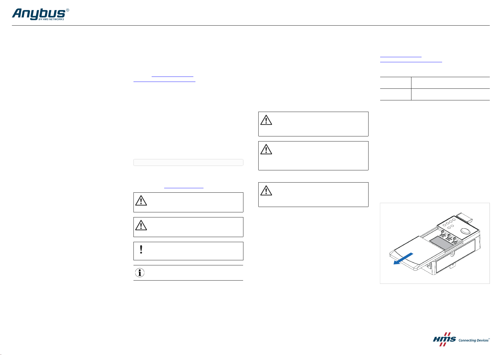
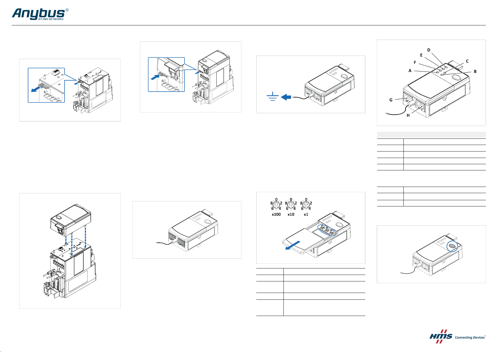
Attach the E300 Communication Module
1. Pull out the locking tab located on the upper left side of
theE300 Relay Control Module.
3. To lock the modules, push in the locking tab located on the
upper left side of the E300 Relay Control Module.
Connecting to Ground
Motor protection function:
Ground Fault – zero sequence method (50 N)
► Connect the Green Wire to Functional Earth (Ground).
LED Guide
E300 Communication Module LED Indicators
Position
A
B
C
D Power
LED Indicator
Link 1 Status and RJ45 Port G status
Link 2 Status and RJ45 Port H status
Network Status
2. Attach the E300 Communication Module to the E300 Relay
Control Module.
© 2020 HMS Industrial Networks
Box 4126, 300 04 Halmstad, Sweden
SP2873 1.0 / 2020-11-16 / 20639
Connecting to Modbus TCP Network
The E300 Communication Module has two RJ45 ports that act as an
Ethernet switch.
The E300 Communication Module listens for incoming Modbus TCP
connections on TCP port 502.
Up to four simultaneous Modbus TCP connections are supported.
IP Address Setting Via Rotary Switches
Node Address
001 - 254
255 - 887
889 - 999
888
000
► A power cycle is required for the changes to take effect.
Function
Set IP Address to 192.168.1.xxx
Configure the module to “Use configured settings”,
values from non volatile storage.
Reset to factory defaults
Configure the module to “Use configured settings”,
values from non volatile storage.
Enter Administration mode
E300 Communication Module LED Indicators (continued)
Position
E
F
LED Indicator
TRIP/WARN
Module Status
Test/Reset
Test: Ensure that the E300 Relay is untripped. To open the trip relay
contact: Press the Test/Reset button for 2 seconds.
Reset: Ensure that the E300 Relay is tripped. To close the trip relay
contact: Press and immediately relese the Test/Reset button.
 Loading...