

Page 1

Anybus®CompactCom™40
SOFTWARE DESIGN GUIDE
HMSI-216-125 4.0 en-US ENGLISH
Page 2

Important User Information
Disclaimer
The information in this document is for informational purposes only. Please inform HMS Industrial Networks of any
inaccuracies or omissions found in this document. HMS Industrial Networks disclaims any responsibility or liability
for any errors that may appear in this document.
HMS Industrial Networks reserves the right to modify its products in line with its policy of continuous product
development. The information in this document shall therefore not be construed as a commitment on the part of
HMS Industrial Networks and is subject to change without notice. HMS Industrial Networks makes no commitment
to update or keep current the information in this document.
The data, examples and illustrations found in this document are included for illustrative purposes and are only
intended to help improve understanding of the functionality and handling of the product. In view of the wide range
of possible applications of the product, and because of the many variables and requirements associated with any
particular implementation, HMS Industrial Networks cannot assume responsibility or liability for actual use based on
the data, examples or illustrations included in this document nor for any damages incurred during installation of the
product. Those responsible for the use of the product must acquire sufficient knowledge in order to ensure that the
product is used correctly in their specific application and that the application meets all performance and safety
requirements including any applicable laws, regulations, codes and standards. Further, HMS Industrial Networks will
under no circumstances assume liability or responsibility for any problems that may arise as a result from the use of
undocumented features or functional side effects found outside the documented scope of the product. The effects
caused by any direct or indirect use of such aspects of the product are undefined and may include e.g. compatibility
issues and stability issues.
Anybus®CompactCom™40 Software Design Guide
HMSI-216-125 4.0 en-US
Page 3

Table of Contents
Page
1 Preface ................................................................................................................................. 5
1.1 About this Document....... .................................. ................. ................. ............................. 5
1.2 Related Documents ........... .............. ................. ................. .................................. ............. 5
1.3 Document History .. ................. ................. .................................. ................. ................. .... 5
1.4 Document Conventions .................... ................. ............................... .................... ............. 7
1.5 Document Specific Conventions................ ................. ................. .................................. ...... 7
1.6 Trademarks................................ .............. ................. ................................................... ... 8
2 About the Anybus CompactCom 40 ................................................................................... 9
2.1 General Information .............................. ................. .................... ............................... ....... 9
2.2 Features ............... ................. ................. .................................. ................. ................. .... 9
3 Software Introduction....................................................................................................... 10
3.1 Background.................... ..................................... ............................... ........................... 10
3.2 The Object Model ........ ................. .................... ............................... ................. ............. 12
3.3 Network Data Exchange ............................. ................. ................................................... . 15
3.4 Diagnostics ................ .................... ................. .............. ................. .................... ........... 16
3.5 File System ... ............................... .................... ................. ............................... ............. 17
3.6 Modular Device ............... ................. ..................................... .............. ................. ......... 19
3.7 SYNC...... .............. ................. ................. .................................. ................. ................. .. 19
3.8 Multilingual Support ......... ................. .............. .................... ................. ................. ......... 24
3.9 Firmware Download ......... ................. .................................. ................. ................. ......... 25
4 Host Communication Layer............................................................................................... 28
4.1 General Information .............................. ................. .................... ............................... ..... 28
4.2 Memory Map ........... ................. ................................................... ................. ................ 29
4.3 Communications Registers.............................. .............. ................. .................................. 30
5 Parallel Host Communication ........................................................................................... 35
5.1 Flow Control .............. .................... ................. .............. ................. .................... ........... 35
5.2 Anybus Event Driven Watchdog .................... ............................... ................. .................... 35
5.3 Application Event Driven Watchdog .......... ................. .............. ................. .................... .... 36
6 SPI Host Communication .................................................................................................. 37
6.1 General Information .............................. ................. .................... ............................... ..... 37
6.2 SPI Frame Format.............. ................. .............. ................. ............................................. 37
6.3 Interrupts ........ ................................................... ................. ......................................... 38
6.4 Message Fragmentation . ................. .............. ................. .................... ................. ............ 38
6.5 SPI Error Handling .................................. ............................... ................. .................... .... 39
6.6 Application Event Driven Watchdog .......... ................. .............. ................. .................... .... 40
Anybus®CompactCom™40 Software Design Guide
HMSI-216-125 4.0 en-US
Page 4

7 Shift Register Host Communication ................................................................................. 41
7.1 General Information .............................. ................. .................... ............................... ..... 41
7.2 Reset ... ................................................... ................. ................................................... . 41
8 Serial Host Communication (UART).................................................................................. 42
8.1 General Information .............................. ................. .................... ............................... ..... 42
9 The Anybus State Machine ............................................................................................... 43
9.1 General Information .............................. ................. .................... ............................... ..... 43
9.2 State Dependent Actions ................................ ............................... .................................. 44
10 Object Messaging .............................................................................................................. 45
10.1 General Information .............................. ................. .................... ............................... ..... 45
10.2 Message Layout.............. .............. .................... ................. ................. .............. ............. 46
10.3 Message Segmentation ............. ................. ................. .................................. ................. . 46
10.4 Data Format........................ ................. ................. .................................. ................. ..... 49
10.5 Command Specification............ ................. ................................................... ................. .. 51
11 Initialization and Startup .................................................................................................. 57
11.1 General Information .............................. ................. .................... ............................... ..... 57
11.2 Startup Procedure.................................. ................. ............................... .................... .... 57
11.3 Anybus Setup (SETUP State).............. ................. ................. .............. .................... ........... 59
11.4 Network Initialization (NW_INIT State)...... ................. .................... .............. ................. ..... 60
12 Anybus Module Objects.................................................................................................... 61
12.1 General Information .............................. ................. .................... ............................... ..... 61
12.2 Object Revisions ......................... ................. ................................................... ............... 61
12.3 Anybus Object (01h) ............. ................. ................................................... ................. ..... 62
12.4 Diagnostic Object (02h) . ................. .................... ............................... ................. ............. 69
12.5 Network Object (03h) ........................ ..................................... .............. ................. ......... 74
12.6 Network Configuration Object (04h) . .................... ................. ................. .............. ............. 81
12.7 Anybus File System Interface Object (0Ah). ................. .................... .............. ................. ..... 83
12.8 Functional Safety Module Object (11h) ............. ............................... .................................. 98
Anybus®CompactCom™40 Software Design Guide
HMSI-216-125 4.0 en-US
Page 5

13 Host Application Objects ................................................................................................ 105
13.1 General Information .............................. ................. .................... ............................... ... 105
13.2 Implementation Guidelines...................... ................. ................. .............. .................... .. 105
13.3 Functional Safety Object (E8h)................................ ................. ....................................... 107
13.4 Application Data Object (FEh).......... .................... ................. .............. ................. ........... 109
13.5 Application Object (FFh) .... ................. ..................................... .............. ................. ....... 118
13.6 Application File System Interface Object (EAh) ................. ................. ................................ 130
13.7 Assembly Mapping Object (EBh) .... ................. ................. .................... .............. ............. 133
13.8 Modular Device Object (ECh) ................................. .............. ................. ......................... 136
13.9 Sync Object (EEh) . .................... ................. ................. .............. .................... ................ 138
13.10 Host Application Specific Object (80h) ........... .............. ................. ................. .................. 140
A Categorization of Functionality ...................................................................................... 141
A.1 Basic........ ................. .................... ................. .............. ................. .................... ......... 141
A.2 Extended ............ .................................. ................. ................. .............. .................... .. 141
B Network Comparison ...................................................................................................... 142
B.1 Network Specific Comments . ................. .................................. ................. ................. .... 144
C Industrial Ethernet Network Comparison...................................................................... 145
D Object Overview.............................................................................................................. 147
D.1 Anybus Module Objects ....... ................. .................................. ................. ................. .... 147
D.2 Host Application Objects ... ................. .............. .................... ................. ................. ....... 148
E Conformance Test Information ...................................................................................... 149
E.1 EtherCAT .............. ................. ................. .................................. ................. ................. 149
E.2 CC-Link................ ................. .............. .................... ................. ................. .............. .... 150
E.3 Ethernet POWERLINK............... .............. ................. .................... ............................... ... 151
E.4 EtherNet/IP................................ ............................... ..................................... ............. 152
E.5 DeviceNet..... .............. ................. .................... ................. .............. ................. ........... 152
E.6 Modbus-TCP ............................. ..................................... ............................... .............. 152
F Runtime Remapping of Process Data............................................................................. 154
F.1 SPI Mode ............ .................... ................. ................. .............. .................... ................ 154
F.2 Parallel Mode, 8/16 Bits, Event Driven ................ .............. .................... ................. .......... 156
F.3 Backwards Compatible Modes................. ................................................... ................. ... 157
F.4 Example: Remap_ADI_Write_Area ........... ................. .................... .............. ................. ... 161
Anybus®CompactCom™40 Software Design Guide
HMSI-216-125 4.0 en-US
Page 6

G CRC Calculation (16–bit) ................................................................................................. 162
G.1 General................................................ ................. ............................... .................... .. 162
G.2 Example .......... ..................................... ............................... ................. .................... .. 162
G.3 Code Example .. ................................................... ................. ................. ...................... 163
H CRC Calculation (32–bit) ................................................................................................. 165
H.1 Example .................................... .............. ................. ..................................... ............. 165
H.2 Code Example ......................... ................. ................. .................................. ................ 165
I Timing & Performance .................................................................................................... 166
I.1 General Information .............................. ................. .................... ............................... ... 166
I.2 Internal Timing ................. ................. ................. ................................................... ...... 166
J Backward Compatibility.................................................................................................. 168
J.1 Initial Considerations ........... ................. .................................. ................. ................. .... 168
J.2 Hardware Compatibility ........................................ ................. ................. ...................... 168
J.3 General Software ..................... ................. ................. .................................. ................ 173
Anybus®CompactCom™40 Software Design Guide
HMSI-216-125 4.0 en-US
Page 7

Preface 5 (176)
1 Preface
1.1 About this Document
This document is intended to provide a good understanding of the Anybus CompactCom
platform. It does not cover any of the network specific features offered by the Anybus
CompactCom 40 products; this information is available in the appropriate Network Guide.
The reader of this document is expected to be familiar with high level software design and
industrial network communication systems in general. For additional information,
documentation, support etc., please visit the support website at www.anybus.com/support.
1.2 Related Documents
Document
Anybus CompactCom M40 Hardware Design Guide
Anybus CompactCom B40 Design Guide
Anybus CompactCom Host Application Implementation Guide
Anybus CompactCom 40 Network Guides (separate document for
each supported fieldbus or network system)
Author
HMS HMSI-216-126
HMS HMSI-27-230
HMS HMSI-27-334
HMS
Document ID
1.3 Document History
Version
0.50 2013-07-02
0.60 2013-12-20
1.00 2014-03-28
1.10 2014-05-26
1.20 2014-08-15
1.21 2014-08-26
1.20 2014-11-10
1.31 2015-02-06
2.00 2015-09-24
3.0 2016-08-31
3.1 2017-04-03
3.2 2017-06-15
3.3 2017-07-10
3.4 2017-11-28
3.5 2018-03-09
3.6 2018-05-28
3.7 2018-09-19
3.8 2018-10-23 Minor corrections
Date
Description
New document
General update
Major update
Major update
Major update
Major update
Major update
Minor update
Major update
Moved from FM to DOX
Major update
CC-Link IE Field added
Misc. updates and corrections
BACnet/IP added
Misc. updates and corrections
Added attr #7 to Application Object (FFh)
Updated information on LED status register
Added appendix on backward compatibility
Added attr #8 - #11 to Application Object (FFh)
Minor updates
Misc. updates
Comparison tables updated for EPL and ECT
Misc. updates
Updates for MQTT support
®
Anybus
CompactCom™40 Software Design Guide
HMSI-216-125 4.0 en-US
Page 8

Preface 6 (176)
Version
Date
3.9 2019-03-01
4.0 2019-11-11
Description
Corrections to Module Device object description
Added info on CANopen module
Minor updates
Rebranded
Updated Anybus Ojbect (01h)
Minor updates
Changed disclaimer
®
Anybus
CompactCom™40 Software Design Guide
HMSI-216-125 4.0 en-US
Page 9
Preface 7 (176)
1.4 Document Conventions
Numbered lists indicate tasks that should be carried out in sequence:
1. First do this
2. Then do this
Bulleted lists are used for:
• Tasks that can be carried out in any order
• Itemized information
► An action
→ and a result
User interaction elements (buttons etc.) are indicated with bold text.
Program code and script examples
Cross-reference within this document: Document Conventions, p. 7
External link (URL): www.hms-networks.com
WARNING
Instruction that must be followed to avoid a risk of death or serious injury.
Caution
Instruction that must be followed to avoid a risk of personal injury.
Instruction that must be followed to avoid a risk of reduced functionality and/or damage
to the equipment, or to avoid a network security risk.
Additional information which may facilitate installation and/or operation.
1.5 Document Specific Conventions
• The terms “Anybus” or “module” refers to the Anybus CompactCom module.
• The terms “host” or “host application” refer to the device that hosts the Anybus.
• Hexadecimal values are written in the format NNNNh or 0xNNNN, where NNNN is the
hexadecimal value.
• Intel byte order is assumed unless otherwise stated.
• Object Instance equals Instance #0.
• Object Attributes resides in the Object Instance.
• The terms “Anybus implementation” and “Anybus version” generally refers to the
implementation in the Anybus module, i.e. network type and internal firmware revision.
• Unless something is clearly stated to be optional, it shall be considered mandatory.
• When writing, fields declared as “reserved” shall be set to zero.
• When reading, fields bits declared as “reserved” shall be ignored.
• Fields which are declared as “reserved” must not be used for undocumented purposes.
Anybus®CompactCom™40 Software Design Guide
HMSI-216-125 4.0 en-US
Page 10

Preface 8 (176)
• A byte always consists of 8 bits.
• A word always consists of 16 bits.
1.6 Trademarks
• Anybus®is a registered trademark of HMS Industrial Networks.
• EtherNet/IP is a trademark of ODVA, Inc.
• DeviceNet is a trademark of ODVA, Inc.
•
EtherCAT®is a registered trademark and
patented technology, licensed by Beckhoff Automation GmbH, Germany.
All other trademarks are the property of their respective holders.
Anybus®CompactCom™40 Software Design Guide
HMSI-216-125 4.0 en-US
Page 11

About the Anybus CompactCom 40 9 (176)
2 About the Anybus CompactCom 40
2.1 General Information
The Anybus CompactCom 40 network communication module is a powerful communication
solution for demanding industrial applications. It is ideal for high performance, synchronized
applications such as servo drive systems. Typical applications are PLCs, HMIs, robotics, AC/DC
and servo drives.
The Anybus CompactCom software interface is designed to be network protocol independent,
allowing the host application to support all major networking systems using the same software
driver, without loss of functionality.
To provide flexibility and room for expansion, an object oriented addressing scheme is used
between the host application and the Anybus module. This allows for a very high level of
integration, since the host communication protocol enables the Anybus module to retrieve
information directly from the host application using explicit object requests rather than memory
mapped data.
The Anybus CompactCom 40 series is backward compatible with the Anybus
CompactCom 30 series though the 40 series has significantly better performance and
include more functionality than the 30 series. The 40 series is backward compatible with
the 30 series in the sense that an application developed for the 30 series should be
possible to use with the 40 series products, even though minor application code changes
may be necessary.
The 40 series products can thus not replace 30 series products as is.
2.2 Features
• Hardware support for triple buffered process data
• Black channel interface, offering a transparent channel for safety communication
• Host interface is network protocol independent
• Multilingual support
• High level of integration
• Synchronization support
• 8-bit and 16-bit parallel modes
• SPI mode
• Stand-alone shift register mode
• Serial interface mode (UART)
• Optional support for advanced network specific features
Anybus®CompactCom™40 Software Design Guide
HMSI-216-125 4.0 en-US
Page 12
Software Introduction 10 (176)
0101101101010110010011
0000101010110100111011
1000010101100000100010
0100110010111000000001
0010001101000100001010
Data from Fieldbus
Network Interface
0101101101010110010011
0000101010110100111011
1000010101100000100010
0100110010111000000001
0010001101000100001010
Data to Fieldbus
Network
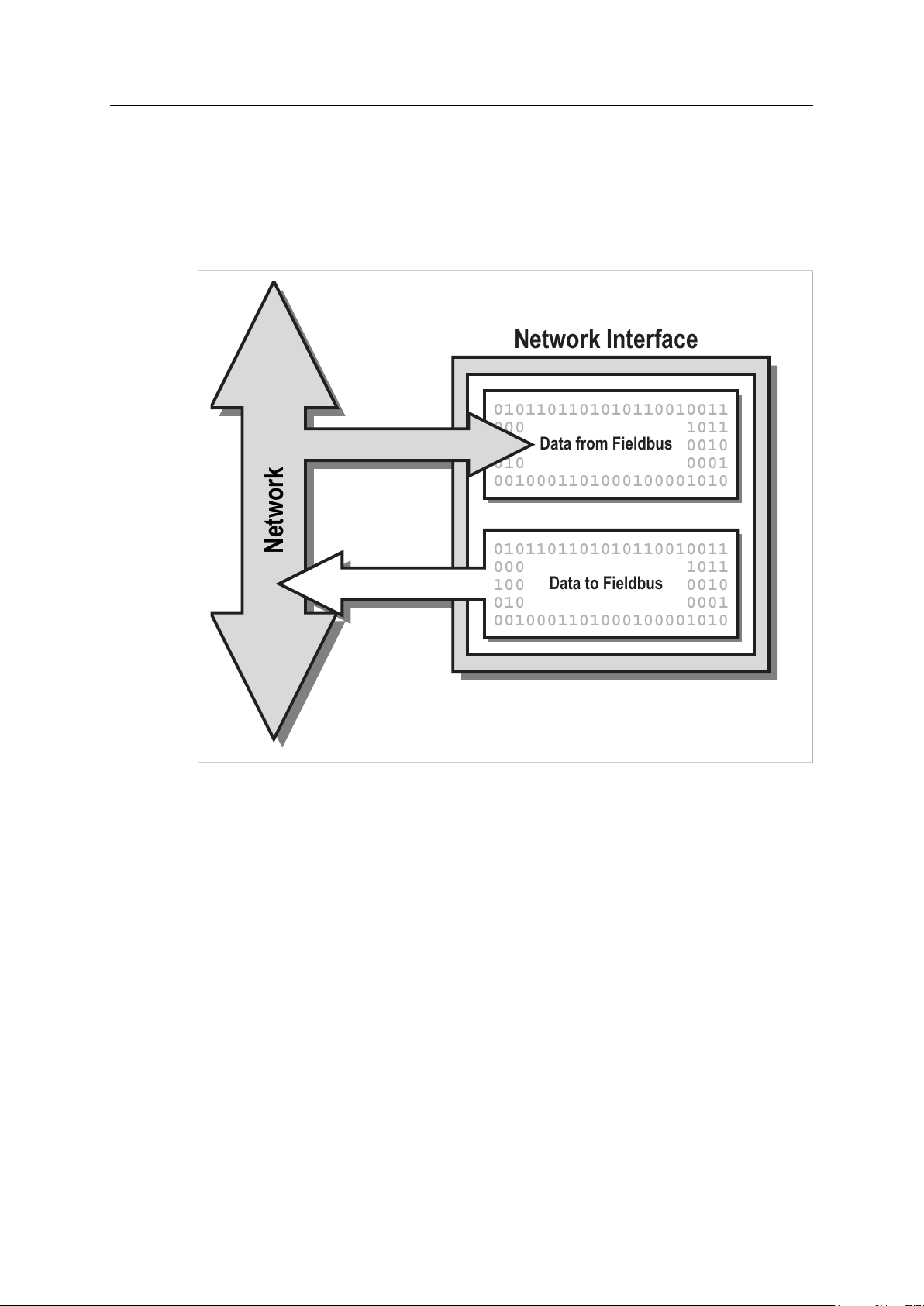
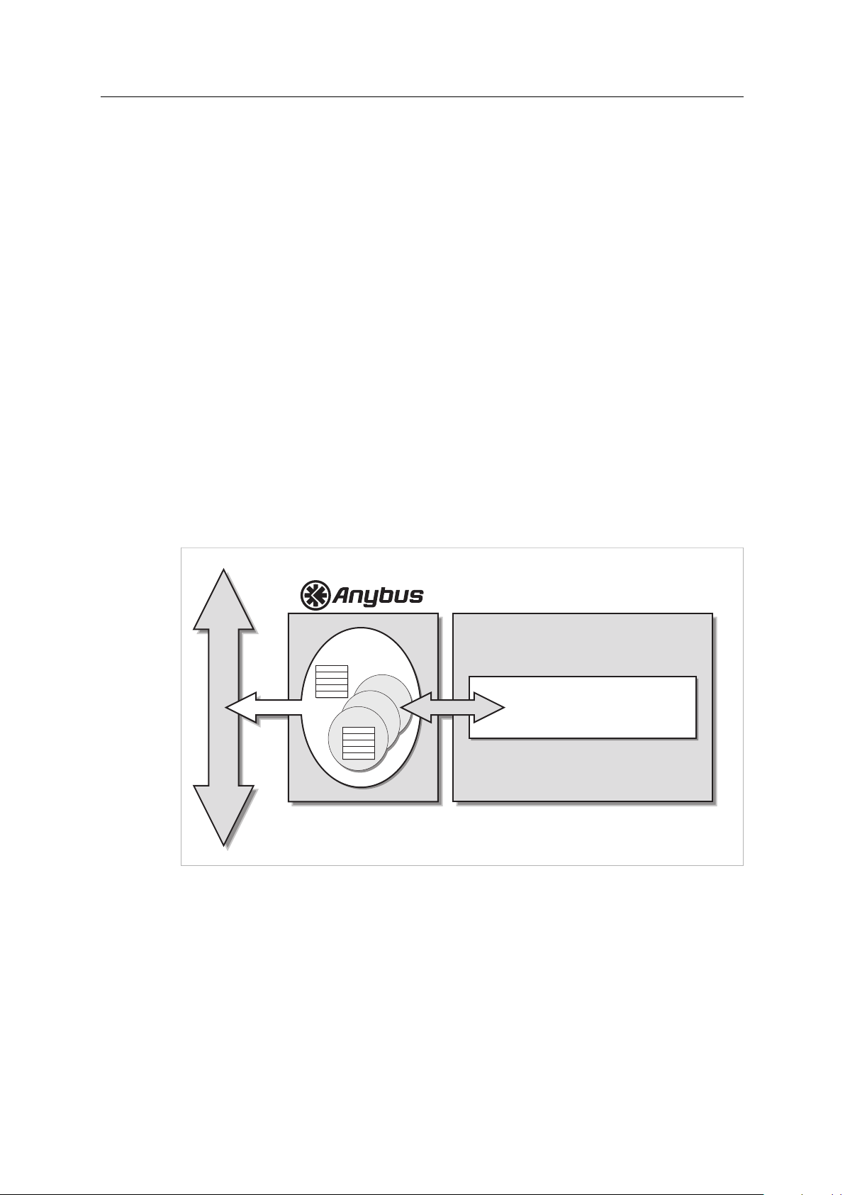
3 Software Introduction
3.1 Background
The primary function of an industrial network interface is to exchange information with other
devices on the network. Traditionally, this has mostly been a matter of exchanging cyclic I/O and
making it available to the host device via two memory buffers.
Fig. 1
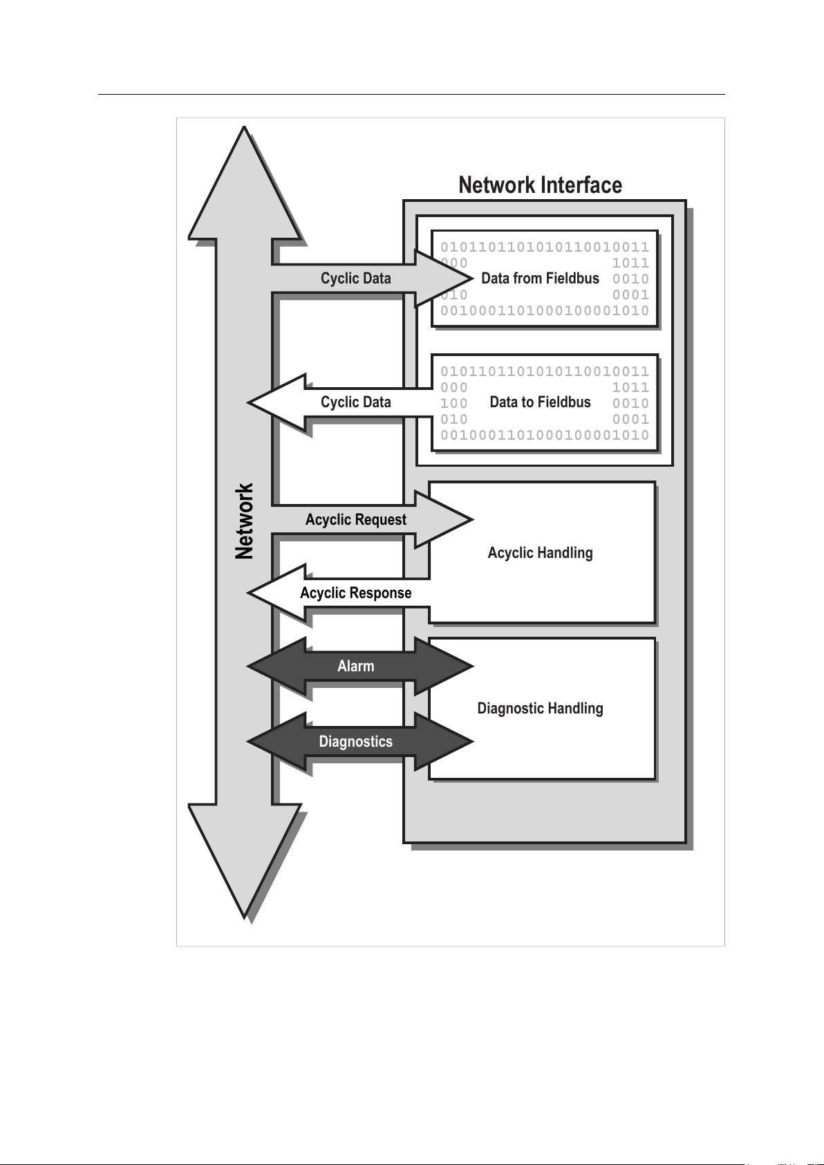
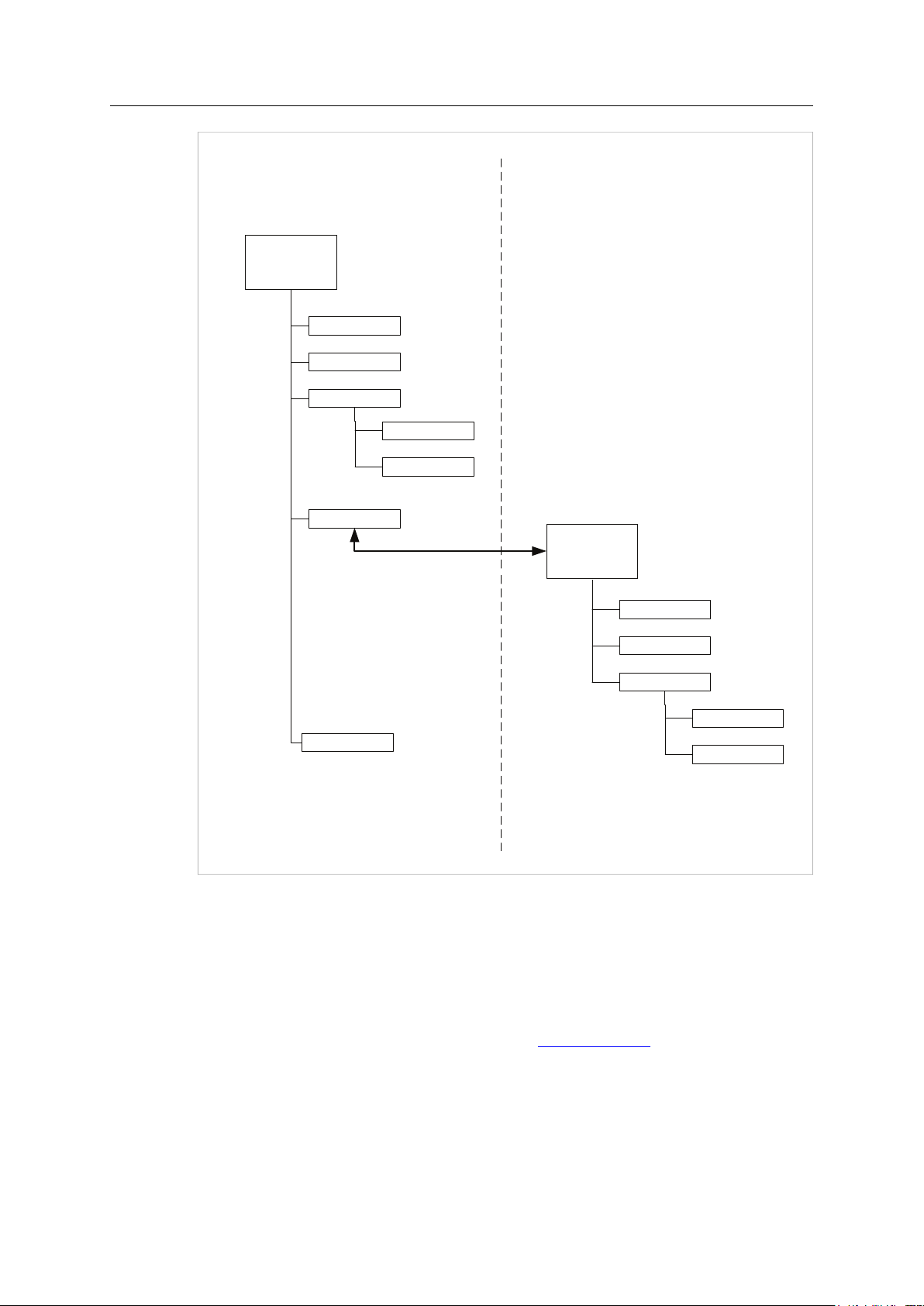
As demand for higher level network functionality increases, the typical role of a network
interface has evolved towards including acyclical data management, alarm handling, diagnostics
etc.
Generally, the way this is implemented differs fundamentally between different networking
systems. This means that supporting and actually taking advantage of this new functionality is
becoming increasingly complex, if not impossible, without implementing dedicated software
support for each network.
By utilizing modern object oriented technology, the Anybus CompactCom provides a simple and
effective way of supporting most networking systems, as well as taking advantage of advanced
network functionality, without having to write separate software drivers for each network.
Acyclic requests are translated in a uniform manner, and dedicated objects provide diagnostic
and alarm handling according to each network standard.
Anybus®CompactCom™40 Software Design Guide
HMSI-216-125 4.0 en-US
Page 13
Software Introduction 11 (176)
0101101101010110010011
0000101010110100111011
1000010101100000100010
0100110010111000000001
0010001101000100001010
Data from Fieldbus
Network Interface
0101101101010110010011
0000101010110100111011
1000010101100000100010
0100110010111000000001
0010001101000100001010
Data to Fieldbus
Diagnostic Handling
Cyclic Data
Cyclic Data
Alarm
Diagnostics
Network
Acyclic Request
Acyclic Response
Acyclic Handling
Fig. 2
®
Anybus
CompactCom™40 Software Design Guide
HMSI-216-125 4.0 en-US
Page 14

Software Introduction 12 (176)
#1
Attributes:
#2
#3
#4
#5
Instance #1
Instance #2
Instance #3
#1
Attributes:
#2
#3
#4
#5
Object #1
(Instance #0)
3.2 The Object Model
3.2.1 Basics
To provide a flexible and logical addressing scheme for both the host application and the Anybus
module, the software interface is structured in an object structured manner. While this approach
may appear confusing at first, it is nothing more than a way of categorizing and addressing
information.
Related information and services are grouped into entities called ‘Objects’. Each object can hold
subentities called ‘Instances’, which in turn may contain a number of fields called ‘Attributes’.
Attributes typically represents information or settings associated with the Object. Depending on
the object in question, Instances may either be static or created dynamically during runtime.
Fig. 3
®
Anybus
CompactCom™40 Software Design Guide
HMSI-216-125 4.0 en-US
Page 15

Software Introduction 13 (176)
3.2.2 Addressing Scheme
Objects, and their contents, are accessed using Object Messaging. Each object message is tagged
with an object number, instance, and attribute, specifying the location of the data or setting
associated with the message.
This addressing scheme applies to both directions; i.e. just like the Anybus module, the
host application must be capable of interpreting incoming object requests and route
them to the appropriate software routines.
Example:
The module features an object called the “Anybus Object”, which groups common settings
relating the Anybus module itself.
In this object, instance #1 contains an attribute called ‘“Firmware version”’ (attribute #2). To
retrieve the firmware revision of the module, the host simply issues a Get Attribute request to
object #1 (Anybus Object), Instance #1, Attribute #2 (Firmware version).
3.2.3 Object Categories
Based on their physical location, objects are grouped into two distinct categories:
Anybus Module Objects These objects are part of the Anybus firmware, and typically controls the behavior of the
Host Application Objects These objects are located in the host application firmware, and may be accessed by the
module and its actions on the network.
Anybus module. This means that the host application must implement proper handling
of incoming object requests.
3.2.4 Standard Object Implementation
The standard object implementation has been designed to cover the needs of all major
networking systems, which means that it is generally enough to implement support for these
objects in order to get sufficient functionality regardless of network type.
Optionally, support for network specific objects can be implemented to gain access to advanced
network specific functionality. Such objects are described separately in each network guide.
Anybus®CompactCom™40 Software Design Guide
HMSI-216-125 4.0 en-US
Page 16

Software Introduction 14 (176)
Anybus Module Objects
The following objects are implemented in the standard Anybus CompactCom 40 firmware:
• Anybus Object
• Diagnostic Object
• Network Object
• Network Configuration Object
• File System Interface Object
• Functional Safety Module Object
• Network Specific Objects
Exactly how much support that needs to be implemented for these objects depends on the
requirements of the host application.
See also...
Anybus Module Objects, p. 61
Host Application Objects
The following objects can be implemented in the host application.
• Application Data Object (Mandatory)
• Application Object (Mandatory)
• Sync Object (Optional)
• Modular Device Object (Optional)
• Assembly Mapping Object (Optional)
• File System Interface Object (Optional)
• Energy Control Object (Optional)
• Functional Safety Object (Optional)
• Network Specific Objects (Optional)
It is mandatory to implement the Application Data Object and the Application Object. The exact
implementation however depends heavily on the requirements of the host application.
See also...
Host Application Objects, p. 105
Anybus®CompactCom™40 Software Design Guide
HMSI-216-125 4.0 en-US
Page 17
Software Introduction 15 (176)
Translation
Application Parameter
Application Parameter
Process Data Handling
Translation
Host Application
0101101101010110010011
0000101010110100111011
1000010101100000100010
0100110010111000000001
0010001101000100001010
Process Data Buffer*
(Read)
Object Response
*) These buffers holds data from ADI's that are mapped to Process Data.
Network
Acyclic Request
Cyclic Data
Acyclic Response
0101101101010110010011
0000101010110100111011
1000010101100000100010
0100110010111000000001
0010001101000100001010
Process Data Buffer*
(Write)
Cyclic Data
(Dedicated Channel)
Application Data
Object
ADI 1
ADI 2
ADI 3
Application Parameter
Object Request
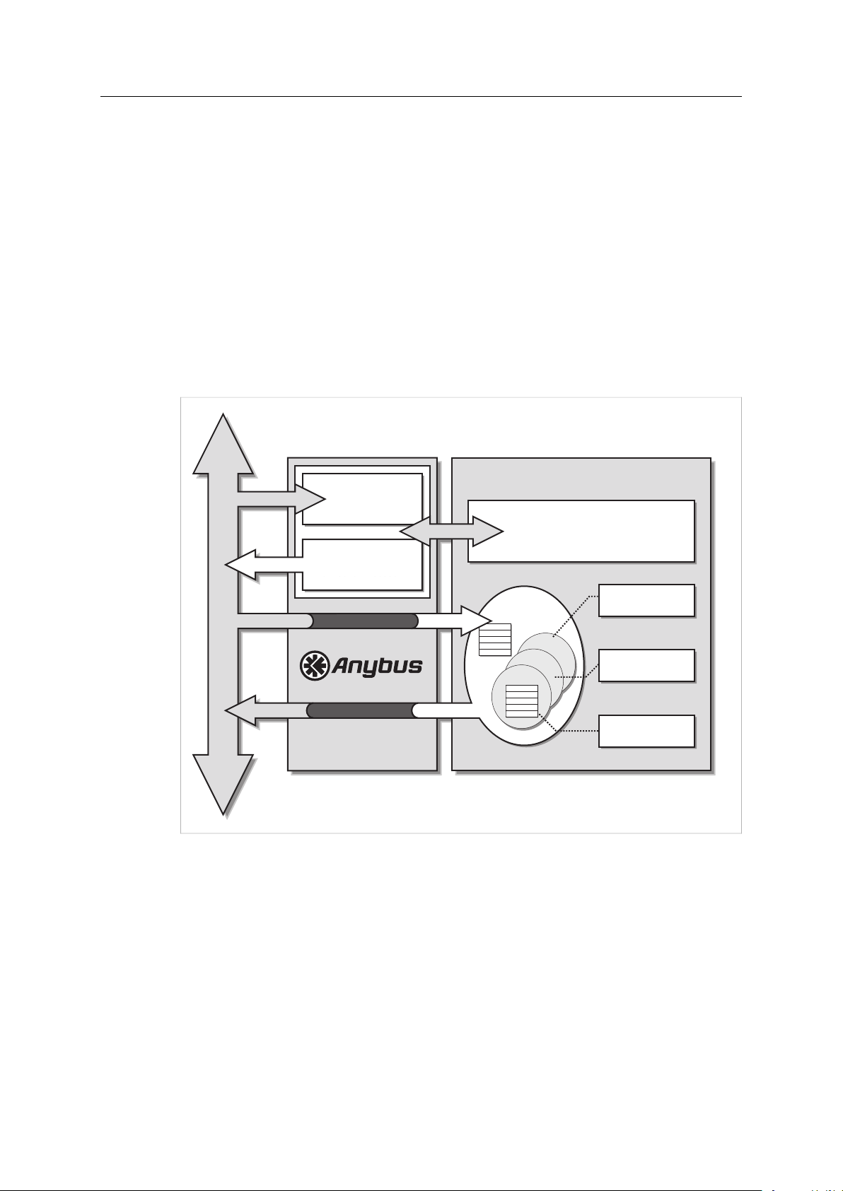
3.3 Network Data Exchange
Data that is to be exchanged on the network is grouped in the Application Data Object. This
object shall be implemented in the host application firmware, and each instance within it (from
now on referred to as “ADI”, i.e. Application Data Instance) represents a block of network data.
ADIs are normally associated with acyclic parameters on the network side. For example, on
DeviceNet and EtherNet/IP, ADIs are represented through a dedicated vendor specific CIP object,
while on PROFIBUS, ADIs are accessed through acyclic DP-V1 read/write services. On EtherCAT
and other protocols that are based on the CANopen Object Dictionary, ADIs are mapped to PDOs,
defined in the object dictionary.
ADIs can also be mapped as Process Data, either by the host application or from the network
(where applicable). Process Data is exchanged through a dedicated data channel in the Anybus
CompactCom host protocol, and is normally associated with fast cyclical network I/O. The exact
representation of Process Data is highly network specific; for example on PROFIBUS, Process
Data correlates to IO data.
Fig. 4
Each ADI may be tagged with a name, data type, range and default value, all of which may be
accessed from the network (if supported by the network in question). This allows higher level
network devices (e.g. network masters, configuration tools etc.) to recognize acyclic parameters
by their actual name and type (when applicable), simplifying the network configuration process.
Some networking systems allows both cyclic and acyclic access to the same parameter. In the
case of the Anybus CompactCom 40, this means that an ADI may be accessed via explicit object
requests and Process Data simultaneously. The Anybus module makes no attempt to synchronize
this data in any way; if necessary, the host application must implement the necessary
mechanisms to handle this scenario.
The Anybus interface uses little endian memory addressing. This means that the byte order is
from the least significant byte (LSB) to the most significant byte (MSB). The Anybus will however
Anybus®CompactCom™40 Software Design Guide
HMSI-216-125 4.0 en-US
Page 18
Software Introduction 16 (176)
Host Application
Network
Diagnostics
Application Diagnostic & Status Handling
Diagnostic
Object
Event
Event
Event
handle ADI values transparently according to the actual network representation (indicated to the
application during initialization). The application driver is responsible for byte swap if required.
Use of this approach is decided because of the following reasons:
• The Anybus can not hold information about the data type of all ADIs due to memory
limitations and start-up time demands.
• The alternative to read the data type prior to every parameter write or read request would
be too time consuming.
See also...
The Anybus State Machine, p. 43
Network Object (03h), p. 74
Functional Safety Object (E8h), p. 107
3.4 Diagnostics
The Anybus CompactCom 40 features a dedicated object for host related diagnostics. To report a
diagnostic event, the host application shall create an instance within this object. When the event
has been resolved, the host simply removes the diagnostic instance again.
Each event is tagged with an Event Code, which specifies the nature of the event, and a Severity
Code, which specifies the severity of the event. The actual representation of this information is
highly network specific.
Fig. 5
See also...
Diagnostic Object (02h), p. 69
Anybus®CompactCom™40 Software Design Guide
HMSI-216-125 4.0 en-US
Page 19

Software Introduction 17 (176)
3.5 File System
The modules in the Anybus CompactCom 40 series have a built-in file system.
For modules not supporting FTP, this makes it possible to store firmware files in the firmware
directory using the File System Interface Object (0Ah). No other access to or use of the file
system is possible for these modules.
For modules supporting FTP, the in-built file system can be accessed from the application and
from the network. The file system can not be deleted.
Three directories are predefined:
VFS
Application This directory provides access to the application file system through the Application File
Firmware
The virtual file system that e.g. holds the web pages of the module.
System Interface Object (EAh) (optional). The directory can not be accessed from the
application, only from the network.
Firmware updates are stored in this directory.
In the firmware folder, it is not possible to use append mode when writing a file. Use
write mode only.
Anybus®CompactCom™40 Software Design Guide
HMSI-216-125 4.0 en-US
Page 20
Software Introduction 18 (176)
Anybus
CompactCom
File system
File 1
File 2
VFS
File 1
File 2
Application
Application
File system
File A1
File A2
Directory A1
File A1:1
File A1:2
The Anybus CompactCom accesses
the application file system through the
Application File System Interface Object.
Anybus CompactCom
Application
Firmware*
* The firmware folder is available to the application
for firmware download in all modules.
Fig. 6
See also...
Anybus File System Interface Object (0Ah), p. 83
Application File System Interface Object (EAh), p. 130
Firmware Download, p. 25
Anybus CompactCom 40 Network Guides, available at www.anybus.com
Anybus®CompactCom™40 Software Design Guide
HMSI-216-125 4.0 en-US
Page 21

Software Introduction 19 (176)
3.6 Modular Device
The modular device functionality makes it possible to model a structure of the process data on
to a number of modules of different types within an application, e.g. for handling digital input or
output, analog input or output, or drives. The ADIs are distributed among the modules and the
number of ADIs per module is configurable. The modules are physically connected to a
backplane, with a number of slots. The first slot is occupied by the coupler, which contains the
Anybus CompactCom module. All other slots may be empty or occupied by modules. When
mapping ADIs to process data, the application shall map the process data of each module in slot
order.
See also:
• Modular Device Object (ECh), p. 136
• Anybus CompactCom 40 Network Guides
3.7 SYNC
3.7.1 General Information
Automation systems involving many devices often require a way to synchronize events. To
achieve this, the devices in the system can share a common timing signal. The Anybus
CompactCom 40 supports a SYNC mechanism via the SYNC object, that is optional to implement
in the application.
The following Anybus CompactCom 40 modules support the SYNC functionality:
• Ethernet POWERLINK
• PROFINET-IRT
• EtherCAT
See also:
• Sync Object (EEh), p. 138.
• Application Status Register, p. 30
• The Anybus State Machine, p. 43 for information of the different states of the Anybus
CompactCom module.
3.7.2 Functionality
For a successful SYNC implementation, there are a number of things to implement and consider.
The network master will configure attributes #1-3 and #7 of the SYNC object through the Anybus
CompactCom module before entering state IDLE or PROCESS_ACTIVE. If the module attempts to
set attributes #1-3 in state IDLE or PROCESS_ACTIVE, the application must respond with error
code 0Dh (Invalid state). For unsupported values for the attributes, the application must respond
with a suitable error code (11h (Value too high), 12h (Value too low) or 0Ch (Value out of range)).
If there is a problem with the configuration as a whole, the application must indicate this in the
application status register. See Application Status Register, p. 30.
The application must indicate its minimum supported cycle time and the required input/output
processing times in attributes #4-6 of the SYNC object at all times. The value of these attributes
can be constant or vary, reflecting the timing required for the current process data mapping.
Anybus®CompactCom™40 Software Design Guide
HMSI-216-125 4.0 en-US
Page 22

Software Introduction 20 (176)
3.7.3 Synchronization Lock
If the application needs time to lock on the SYNC signal, it must write 0001h (“Application not
yet synchronized”) to the application status register. When synchronization lock has been
achieved, and there are no configuration errors, the application must write 0000h to the
application status register and then accept a transition to PROCESS_ACTIVE.
Whenever the application is not locked on the SYNC signal, and attribute #7 “Sync mode” in the
SYNC object is set to “1”, the application must write the most accurate nonzero status code to
the application status register.
See also
Application Status Register, p. 30
3.7.4 SYNC Pulse
The SYNC signal, available from the module’s application connector, indicates the synchronization
event to the application by a positive pulse once every cycle. The positive edge of the SYNC pulse
indicates the synchronization event.
The width of the SYNC pulse is at least 5 µs, with a maximum width of 50% of the cycle time.
The SYNC event is also available to the application as a maskable interrupt. See Interrupt Status
Register, p. 32.
3.7.5 Network Translation
Ethernet POWERLINK does not in itself support synchronization functionality. The SYNC signal
from the module is sent once for each cycle, and can as such be used by the application.
In Anybus CompactCom 40 EtherCAT, parameters and settings are stored in CoE objects 1C32h
and 1C33h.
The Anybus CompactCom 40 PROFINET IRT supports both isochronous and non-isochronous
modes.
For more information, please consult the respective network guides.
Anybus®CompactCom™40 Software Design Guide
HMSI-216-125 4.0 en-US
Page 23

Software Introduction 21 (176)
Cycle time
MI0/SYNC Signal
Input Capture
Output Valid
Min: “Output
Processing”
Max: “Input
Processing”
WRPD (Write Process Data)
Written to Anybus
Input Capture
Point
Output Valid
Point
RDPDI
(Read Process
Data Interrupt
From Anybus)
3.7.6 Anybus CompactCom 40 SYNC Implementation
The Goal of SYNC
To set output data to
different devices
simultaneously.
To capture input data from
different devices
simultaneously.
Fig. 7
The PLC will tell all devices in the network to set the next set of available output data at
the application, when the SYNC signal is sent.
The time when the output data is set at the application is called the Output Valid Point.
The time when the input data is available is called the Input Capture Point.
Handling of Output Data
Each device needs time to handle the new output data before it can be set in the application.
This time is not constant.
The device has to follow these steps:
1. Wait for indication of new output data (indicated by the Anybus CompactCom 40 through
the RDPDI (Read Process Data Interrupt).
2. Read the output data from the Anybus CompactCom 40 when receiving the RDPDI.
3. Process the new output data so that it can be used by the host application
– copy data
– process output variables
– do calculations
– etc
4. Wait for the SYNC signal.
5. When the SYNC signal arrives:
– If “Output Valid” = 0, activate the outputs to the host application.
– If “Output Valid” > 0, start a hardware or a software timer on the positive edge of the
SYNC signal. Activate the outputs to the host application when the timer has reached
“Output Valid”.
See Buffer Control Register, p. 31 and Interrupt Status Register, p. 32 for more information on
RDPD (Read Process Data) and RPDPI (Read Process Data Interrupt)
Anybus®CompactCom™40 Software Design Guide
HMSI-216-125 4.0 en-US
Page 24

Software Introduction 22 (176)
Handling of Input Data
Each device needs time to capture, prepare and send new input data. This time is not constant.
The device has to follow these steps:
1. Wait for the SYNC signal.
2. When the SYNC signal arrives (“Input Capture” point):
– If “Input Valid” = 0, capture the current input process variables of the host application.
– If “Input Valid” > 0, start a hardware or a software timer on the positive edge of the
SYNC signal. Capture the current input process data when the timer has reached “Input
Valid”.
3. Prepare the new input process data so that it can be written to theAnybus CompactCom 40.
4. Write the new process input data to theAnybus CompactCom 40.
Host Application Programming Guidelines
See Sync Object (EEh), p. 138 for more information.
1. Implement the SYNC Object (part 1)
7
Sync mode
8
Supported sync modes
Get/Set
Get UINT16
UINT16
This attribute is used to select synchronization
mode. It enumerates the bits in attribute 8
0: Non synchronous operation. (Default value if
non synchronous operation is supported)
1: Synchronous operation
2 - 65535: Reserved. Any attempt to set sync
mode to an unsupported value shall generate
an error response
A list of the synchronization modes the
application supports. Each bit corresponds to a
mode in attribute 7
Bit 0: 1 = Non synchronous mode supported
Bit 1: 1 = Synchronous mode supported
Bit 2 - 15: Reserved (0)
2. Implement the SYNC Object (part 2)
4 Output processing Get UINT32
5
Input processing Get UINT32
6
Min cycle time
Get UINT32
Minimum required time, in nanoseconds,
between RDPDI interrupt and “Output valid”
Maximum required time, in nanoseconds, from
“Input capture” until write process data has been
completely written to the Anybus CompactCom
40
Minimum cycle time supported by the
application (in nanoseconds)
The time elapsed between receiving an RDPDI interrupt and when the process output
variables have been taken over by the application has to be measured. The maximum time
must be provided by the application when the Anybus CompactCom 40 asks for attribute #4
“Output processing”. The network master has to make sure that the minimum output
processing time is longer than the maximum time measured.
The time elapsed between capturing the input process variables and when the input process
data is written to the CompactCom 40 must be measured. The maximum time must be
provided by the application when the Anybus CompactCom 40 asks for attribute #5 “Input
processing”.
The host application must measure the maximum time needed to handle all process data
(the time from receiving the RDPDI interrupt until the write process data has been written
to the Anybus CompactCom 40). This value must be provided by the application when the
Anybus CompactCom 40 asks for attribute #6 “Min cycle time”.
Anybus®CompactCom™40 Software Design Guide
HMSI-216-125 4.0 en-US
Page 25

Software Introduction 23 (176)
3. Implement the SYNC Object (part 3)
1
Cycle time
2
Output valid
3 Input capture
Get/Set
Get/Set
Get/Set
UINT32
UINT32
UINT32
Application cycle time in nanoseconds
Output valid point relative to SYNC events, in
nanoseconds
Default value: 0
Input capture point relative to SYNC events, in
nanoseconds
Default value: 0
These three attributes can all be set by the Anybus CompactCom 40.
Using attribute #1, “Cycle time”, theAnybus CompactCom 40 informs the host application
about the real used cycle time (by the Set_Attribute command). This value must be
evaluated by the host application and refused if not acceptable (not suitable, e.g. in conflict
with other cyclic tasks of the host application or not within the defined range). If refused,
the Anybus CompactCom 40 will report this to the PLC.
Attributes #2 and #3 reflect functionality present on some networks (e.g. EtherCAT, SERCOS
and PROFINET), where the input capture and output valid points can be fine-tuned. This can
be used to offset one device relative to another by a small amount of time. To support
values other than zero (0), timers will have to be implemented in the application.
4. Implement the Application Status Register
See Application Status Register, p. 30 for more information.
5. Act upon receiving an RDPDI and a SYNC signal
When receiving an RDPDI interrupt, read the output process data from the Anybus
CompactCom 40, prepare it (handle and assign it to process output variables) so that it can
be activated when receiving a SYNC signal.
When receiving a SYNC signal, do the following:
a. Transfer the output process variables to the application immediately.
b. Capture all input process variables immediately.
c. Prepare and assign the input process variables to the input process data.
d. Write the input process data to the CompactCom.
Steps b, c and d must be done within the time specified by attribute #5 “Input processing”.
Steps a and b assumes Output Valid and Input Capture to be zero (0).
Anybus®CompactCom™40 Software Design Guide
HMSI-216-125 4.0 en-US
Page 26

Software Introduction 24 (176)
Cycle time
MI0/SYNC Signal
Max: “Input
Processing”
WRPD Written to
Anybus
Output Valid Point
and
Input Capture Point
The Easiest Realization of a Synchronous Application
Fig. 8
The following steps show how to create a very simple synchronous application.
1. Set up an interrupt routine triggered by the positive SYNC edge. Disable the RDPDI interrupt.
2. In the SYNC interrupt routine:
– Sample the input data and write it to the Anybus CompactCom 40.
– Read the output data from the Anybus CompactCom 40 and start using it immediately.
3. For this application, attribute #4 “Output processing” in the SYNC object should be set to
zero (0). No measurement needed.
4. Attribute #5 “Input processing” must be determined. It can probably be hard coded to a
fixed value, but this is application specific and depend on the complexity of the SYNC
interrupt routine and the application processor performance.
5. For attributes #2 “Output valid” and #3 “Input capture”, only the value zero (0) will be
accepted by the application.
This simple step-by-step method will work in all applications where the process data handling
can be made fast and simple.
3.8 Multilingual Support
Where applicable, the Anybus CompactCom 40 supports multiple languages. This mainly affects
instance names and enumeration strings, and is based on the current language setting in the
Anybus Object. Note that this also applies to Host Application Objects, which means that the
host application should be capable of changing the language of enumeration strings etc.
accordingly.
When applicable, the Anybus CompactCom 40 forwards change-of-language-requests from the
network to the Application Object. It is then up to the host application to grant or reject the
request, either causing the module to change its language settings or to reject the original
network request.
Supported languages:
• English (default)
• German
• Spanish
Anybus®CompactCom™40 Software Design Guide
HMSI-216-125 4.0 en-US
Page 27

Software Introduction 25 (176)
• Italian
• French
See also...
Application Object (FFh), p. 118
3.9 Firmware Download
Download and upgrade of network communication firmware for a specific fieldbus or industrial
network can be performed in different ways, depending on which Anybus CompactCom 40 that
is to be upgraded.
3.9.1 Important
When the Anybus CompactCom 40 is restarted after a firmware download, the application must
wait for the installation to finish before initialization is started. The Anybus CompactCom 40 is
protected against power failure during download and/or installation and will recover upon
restart.
• If download through e.g. Firmware Manager or FTP, is interrupted, please restart the
firmware download process from the beginning.
• To install the new firmware after download is completed, reset the Anybus CompactCom 40.
If the installation of the new firmware is interrupted, e.g. due to power loss, please restart
the Anybus CompactCom 40. The installation process will automatically start from the
beginning and the new firmware will be installed without any further action.
For more information see, Startup Procedure, p. 57
Anybus®CompactCom™40 Software Design Guide
HMSI-216-125 4.0 en-US
Page 28
Software Introduction 26 (176)
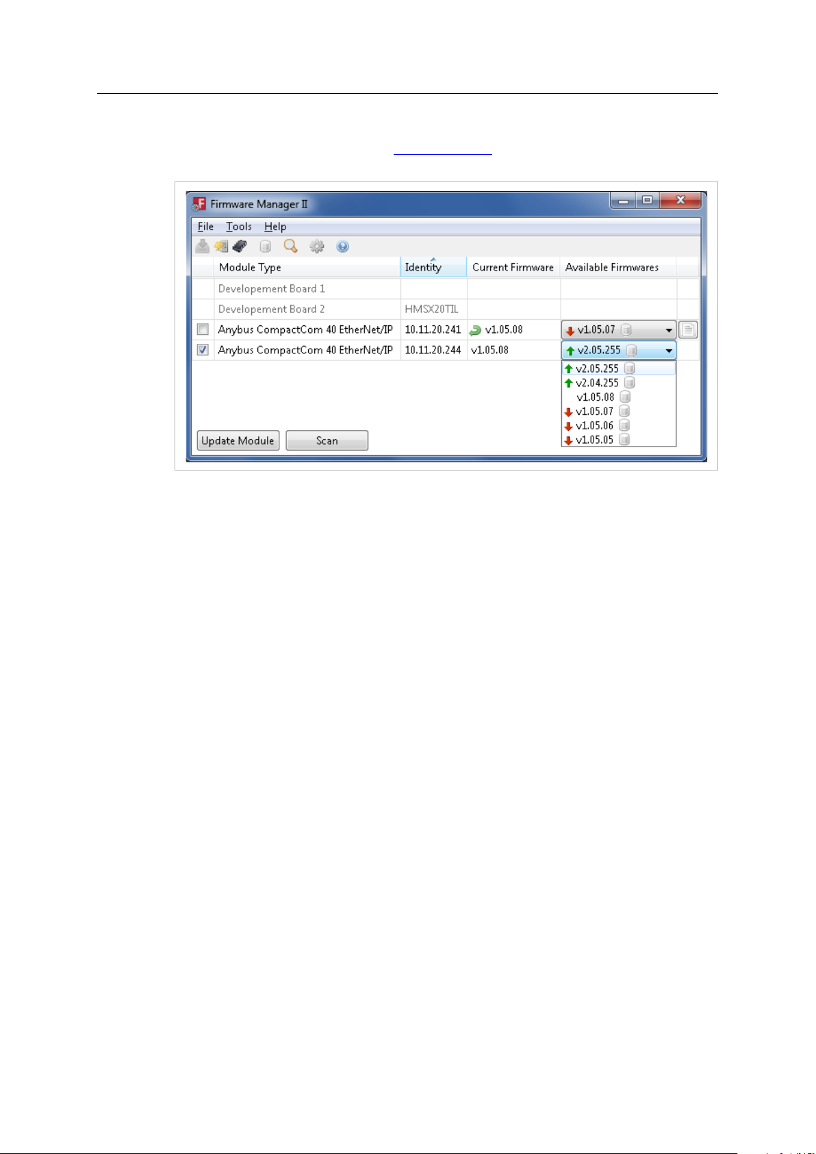
3.9.2 Using Firmware Manager II
This tool is available without cost from www.anybus.com. It can be used to download new
firmware for any Anybus CompactCom 40.
Fig. 9
Using the tool, perform the following steps to download new firmware to the module.
1. Connect a computer with the Firmware Manager II software installed to the network
containing the module.
2. Start the Firmware Manager II tool.
3. Scan the network and find the module.
4. Click the Firmware Repository icon in the menu, to open the Firmware Repository window.
Drag the firmware folder into the window to add the new firmware to the repository. Close
the Firmware Repository window.
5. In the scan window, under the “Available Networks” tab, select the appropriate firmware
for the module. Click the Change Network button. A confirmation window will appear. Click
Yes to start the download of the new firmware. Please make sure that download is
completely finished before continuing.
6. After download, a restart of the module is needed to install the new firmware. If the
application allows it, it is possible to restart the module via the Restart Module button in
the Firmware Manager II tool. If the application does not allow restart from the network, a
manual restart of the module is needed.
For more information, see the help file in the Firmware Manager II software.
Anybus®CompactCom™40 Software Design Guide
HMSI-216-125 4.0 en-US
Page 29

Software Introduction 27 (176)
3.9.3 Using the Internal File System
The internal file system can be accessed via the File System Interface Object. Interfacing this
object from the host application, makes it possible to store the new firmware in the /firmware
directory in the internal file system. The next time the module is started the firmware will be
upgraded. After the firmware is installed, the firmware file is deleted from the /firmware
directory.
In the firmware folder, it is not possible to use append mode when writing a file. Be sure
to use write mode only.
See also ...
• Application File System Interface Object (EAh), p. 130
3.9.4 Using FTP
If the module supports FTP, this can be used to access the file system and upload the new
firmware directly to the /firmware directory. The next time the module is started the firmware
will be upgraded. After the firmware is installed, the firmware file is deleted from the /firmware
directory.
See also ...
• Application File System Interface Object (EAh), p. 130
Anybus®CompactCom™40 Software Design Guide
HMSI-216-125 4.0 en-US
Page 30

Host Communication Layer
4 Host Communication Layer
4.1 General Information
The main communication layer is used by the 8-bit/16-bit parallel modes and the SPI mode. It is
divided into process data read/write areas, message data read/write areas and a number of
control registers.
Below is a detailed description of the memory map and the different control registers.
4.1.1 Communication Basics
The communication between the host and the Anybus CompactCom 40 is simple, fast and
flexible.
The host can read or write process data at any time. It can check for incoming data via the buffer
control register or by enabling appropriate interrupts via the interrupt mask register.
Attempts to access reserved registers will produce unpredictable results. Attempts to
write to a read-only register will produce unpredictable results. Reserved bits shall be
written with zeros (0). Reading reserved bits returns undefined values.
28 (176)
Anybus®CompactCom™40 Software Design Guide
HMSI-216-125 4.0 en-US
Page 31

Host Communication Layer
4.2 Memory Map
The address offset specified below is relative to the base address of the module, i.e. from the
beginning of the area in host application memory space where the interface has been
implemented.
The memory area is not available during reset.
The shaded areas and registers are used for backward compatibility with the Anybus
CompactCom 30 series.
29 (176)
Byte Address Word Address
0000h - 0FFFh 0000h - 07FFh Process data, write
1000h - 1FFFh 0800h - 0FFFh Process data, read area
2000h - 25FFh 1000h - 12FFh Message data, write
2600h - 2FFFh 1300h - 17FFh Reserved
3000h - 35FFh 1800h - 1AFFh Message data, read
3600h - 37FFh 1B00h - 1BFFh Reserved
3800h - 38FFh 1C00h - 1C7Fh Process data, write
3900h - 39FFh 1C80h - 1CFFh Process data, read area
3A00h - 3AFFh 1D00h - 1D7Fh Reserved
3B00h - 3C06h 1D80h - 1E03h Message data, write
3C07h - 3CFFh 1E04h - 1E7Fh Reserved
3D00h - 3E06h 1E80h - 1F03h Message data, read
3E07h - 3FE7h 1F04h - 1FF3h Reserved
3FE8h - 3FEFh 1FF4h - 1FF7h Current network time
3FF0h - 3FF1h 1FF8h Module capability
3FF2h - 3FF3h 1FF9h
3FF4h - 3FF5h 1FFAh Application status
3FF6h - 3FF7h 1FFBh Anybus CompactCom
3FF8h - 3FF9h 1FFCh Buffer control register
3FFAh - 3FFBh 1FFDh Interrupt mask register
3FFCh - 3FFDh 1FFEh
3FFEh 1FFFh Control register
3FFFh
Area Bytes Access,
area
area
area
area
area
area
register
LED status register 2 R
register
module status register
Interrupt status
register
Status register 1 R
4096
4096 R
1536
2560
1536 R
512
256
256 R
256
263
249
263 R
481
8 R
2 R
2
2 R
2
2
2
1
seen from
host
R/W
R/W
-
-
R/W
-
R/W
-
-
R/W
R/W
R/W
R/W
R/W
Notes
This is the total size of the
area. The actual size
depends on the network.
For network specific
process area sizes, see
Network Comparison, p.
142.
Applicable to all protocols
Applicable to all protocols
Applicable to the event
driven protocol.
Applicable to the half
duplex protocol
If an application is to use “current network time”, the network time must first be sampled. This is
performed by writing to this register. The register will be updated with the actual value from the
network, which then can be read by the application.
C-programmers are reminded to declare the entire shared memory area as volatile.
Anybus®CompactCom™40 Software Design Guide
HMSI-216-125 4.0 en-US
Page 32

Host Communication Layer
4.3 Communications Registers
4.3.1 Module Capability Register
The module capability register contains one of the values below, indicating module type. The
application should determine the module type by examining the low byte only. The high byte is
reserved for future use.
30 (176)
Value
0000h Active Anybus CompactCom 30 series module, supporting the half duplex protocol only
000Bh Active Anybus CompactCom 40 series module, supporting the event driven as well as the half
000Ch Active Anybus IP with parallel AXI bus
0101h
0202h
0303h
0404h (reserved)
0505h Passive Bluetooth
0606h - 0909h (reserved)
0A0Ah
0C0Ch - 0F0Fh (reserved)
All passive modules belong to the Anybus CompactCom 30-series. There are no passive modules in the
Anybus CompactCom 40-series.
4.3.2 LED Status Register
The first 8 bits of this register reflect the LED status, as represented by the value of the instance
attribute LED status (#13) in the Anybus Object. See Anybus Object (01h), p. 62 for more
information. The following for bits reflect status of the signals LED5A, LED5B, LED6A and LED6B.
Module Type
8 bit parallel and serial modes
duplex protocol
8 bit/16 bit parallel, shift register, SPI and serial modes
Passive RS232
Passive RS422
Passive USB
Passive RS485
If a bit is set to 1, the status of the corresponding LED is ON.
Bit
0 LED1A
1 LED1B
2 LED2A
3 LED2B
4 LED3A
5 LED3B
6 LED4A
7 LED4B
8 LED5A
9 LED5B
10 LED6A
11 LED6B
12–15
LED Signal
(none)
4.3.3 Application Status Register
The application status register is primarily used in SYNC applications. It is used in applications
where the network in question supports the ability to indicate critical process data errors to the
master. If this is supported, the Anybus CompactCom 40 module will accept and handle the
below listed status codes written by the application.
Anybus®CompactCom™40 Software Design Guide
HMSI-216-125 4.0 en-US
Page 33

Host Communication Layer
This register is optional to use. For networks which do not support indications of critical process
data errors, the module will ignore this register.
The register contains an 8 bit value. When the register is accessed from the parallel interface, the
value is provided as a word aligned value with the upper 8 bits always set to 0. See Memory Map,
p. 29.
31 (176)
Value
00h
01h Not yet synchronized Not ready for transition to state PROCESS_ACTIVE
02h Sync configuration error A problem with the current attribute values in the Sync object
03h Read process data configuration
04h Write process data configuration
05h Synchronization loss The application has lost synchronization lock
06h Excessive data loss The application has detected a significant loss of process data from
07h
Error
No error
error
error
Output error
Description
Ready for transition to state PROCESS_ACTIVE
(Default)
prevents the transition to state PROCESS_ACTIVE
A problem with the current read process data mapping prevents
the transition to state PROCESS_ACTIVE
A problem with the current write process data mapping prevents
the transition to state PROCESS_ACTIVE
If the Anybus CompactCom is in the state PROCESS_ACTIVE, it will
change to a lower state
the network
If the Anybus CompactCom is in the state PROCESS_ACTIVE, it will
change to a lower state
Application malfunction
If the Anybus CompactCom is in the state PROCESS_ACTIVE, it will
change to a lower state
The Anybus state machine is described in The Anybus State Machine, p. 43
4.3.4 Anybus CompactCom Module Status Register
This register contains the current Anybus CompactCom module state, and a supervised bit
indicated by the Anybus CompactCom module. The Anybus state machine is described in The
Anybus State Machine, p. 43
Bit Name
0 - 2
3
4 - 15
S[0..2] The current Anybus CompactCom module state
Supervised bit 1 = Supervised by another network device
-
4.3.5 Buffer Control Register
This register is used by the application to control the event driven communication with the
Anybus CompactCom module.
By writing to this register, it is possible to trigger appropriate events. Write “1” to trigger bits,
and “0” to leave bits unaffected.
Reading this register gives the current status of the different memory areas.
For more information about how to implement and use bits 0–3, seeCommunication Basics, p. 35
Description
0 = Not supervised by another network device
See Supervised Bit (SUP), p. 34.
Reserved (0)
Anybus®CompactCom™40 Software Design Guide
HMSI-216-125 4.0 en-US
Page 34

Host Communication Layer
32 (176)
Bit
0 WRPD
1 RDPD
2 WRMSG
3 RDMSG
4 ANBR
5 APPR
6 APPRCLR
7 - 15
Name
(Write Process Data)
(Read Process Data)
(Write Message Data)
(Read Message Data)
(Anybus Ready)
(Application Ready)
(Application Ready
Clear)
-
Description
The application shall write “1” to this bit when new data has been written.
When the module has updated the read process data, this bit will be read as
“1”.
The application shall write “1” to this bit to request the latest read process
data. By doing this the bit is cleared.
Note: “updated” data does not necessarily mean “changed” data.
This bit is read as “1” when the write message area is occupied.
This bit is cleared by the module when the write message area is available for
a new message.
When the application sends a write message to the module, it shall write “1”
to this bit.
The application is only allowed to write to the write message area while this
bit is “0”.
Note: it is only allowed to write command messages when the ANBR bit is also
set.
This bit will be read as “1” when the module has posted a new read message.
The application writes “1” to this bit to acknowledge the message. By doing
this the bit is cleared.
The application is only allowed to read the read message area while this bit is
“1”.
This bit is set to “1” when the module is ready to receive a new command
message.
The application is only allowed to send command messages while this bit is “1”.
This bit can only change from “1” to “0” while WRMSG is “1”.
It can change from “0” to “1” at any time.
The application writes ‘1’ to this bit when it is ready to receive a new
command message.
The module will only send command messages while this bit is “1”.
Use APPRCLR to set this bit to “0”.
The application can write “1” to this bit to clear the APPR bit. This is only
allowed when RDMSG is “1”.
Reserved
4.3.6 Interrupt Mask Register
This register makes it possible for the application to enable or disable individual interrupts,
according to the table below.
Bit
0 RDPDIEN
1 RDMSGIEN
2 WRMSGIEN
3 ANBRIEN
4 STATUSIEN
5
6 SYNCIEN
7 - 15
Name
-
-
4.3.7 Interrupt Status Register
The module indicates the pending interrupts in this register, according to the table below.
Description
Set this bit to “1” to enable interrupt for when the RDPD bit in the buffer
control register transitions from “0” to “1”.
Set this bit to “1” to enable interrupt for when the RDMSG bit in the buffer
control register transitions from “0” to “1”.
Set this bit to “1” to enable interrupt for when the WRMSG bit in the buffer
control register transitions from “1” to “0”.
Set this bit to “1” to enable interrupt for when the ANBR bit in the buffer
control register transitions from “0” to “1”.
Set this bit to “1” to enable interrupt for an Anybus CompactCom module
status register change.
Reserved
Set this bit to “1” to enable interrupt for a SYNC event.
Reserved
Anybus®CompactCom™40 Software Design Guide
HMSI-216-125 4.0 en-US
Page 35

Host Communication Layer
33 (176)
Bit Name
0 RDPDI
1 RDMSGI
2 WRMSGI
3 ANBRI
4 STATUSI
5 PWRI
6 SYNCI
7 - 15
-
Description
This bit is set to “1” when RDPD in the buffer control register transitions from
“0” to “1”.
The application shall write “1” to this bit to set it to “0”.
This bit is set to “1” when RDMSG in the buffer control register transitions
from “0” to “1”.
The application shall write “1” to this bit to set it to “0”.
This bit is set to “1” when WRMSG in the buffer control register transitions
from “1” to “0”.
The application shall write “1” to this bit to set it to “0”.
This bit is set to “1” when ANBR in the buffer control register transitions from
“0” to “1”.
The application shall write “1” to this bit to set it to “0”.
This bit is set to “1” on an Anybus CompactCom module status register change.
The application shall write “1” to this bit to set it to “0”.
This bit is set to “1” when the module is ready to start communication after a
power-up or a hardware reset.
The application shall write “1” to this bit to set it to “0”.
This bit is set to “1” on each SYNC event.
The application shall write “1” to this bit to set it to “0”.
Reserved
4.3.8 Control Register (Read/Write)
Only used for the half duplex (ping/pong) protocol.
This register controls the communication towards the Anybus CompactCom.
b7 (MSB)
CTRL_T CTRL_M CTRL_R CTRL_AUX
Bit
CTRL_T
CTRL_M
CTRL_R
CTRL_AUX
-
b6 b5 b4 b3 b2 b1
Description
The host application shall toggle this bit when sending a new telegram. CTRL_T must be set to “1” in the
initial telegram sent by the application to the module.
If set, the message subfield in the current telegram is valid.
If set, the host application is ready to receive a new command.
(ignored)
(reserved, set to zero)
4.3.9 Status Register (Read Only)
Only used for the half duplex (ping/pong) protocol.
This register holds the current status of the Anybus CompactCom.
b0 (LSB)
- - - -
b7 (MSB)
STAT_T STAT_M STAT_R STAT_AUX SUP S2 S1 S0
Bit
STAT_T
STAT_M
®
Anybus
CompactCom™40 Software Design Guide
b6 b5 b4 b3 b2 b1
Description
When the module issues new telegrams, this bit will be set to the same value as CTRL_T in the last
telegram received from the host application.
If set, the message subfield in the current telegram is valid.
b0 (LSB)
HMSI-216-125 4.0 en-US
Page 36

Host Communication Layer
34 (176)
Bit
STAT_R
STAT_AUX
SUP
S[0... 2] These bits indicates the current state of the module (see also The Anybus State Machine, p. 43).
Description
If set, the Anybus module is ready to process incoming commands.
See Auxiliary Bit (STAT_AUX, CTRL_AUX), p. 34.
Value:
0:
1:
See Supervised Bit (SUP), p. 34.
S2 S1 S0
0 0 0 SETUP
0 0 1 NW_INIT
0 1 0 WAIT_PROCESS
0 1 1 IDLE
1 0 0 PROCESS_ACTIVE
1 0 1 ERROR
1 1 0
1 1 1 EXCEPTION
Meaning:
Module is not supervised.
Module is supervised by another network device.
Anybus State
(reserved)
The Status Register shall be regarded as cleared at start-up. The first telegram issued by the host
application must therefore not contain a valid message subfield since STAT_R is effectively
cleared (0).
4.3.10 Supervised Bit (SUP)
While the Anybus State Machine reflects the state of the cyclic data exchange, the SUP-bit
indicates the overall status of the network communication, including acyclic communication. For
example, on CIP, this bit indicates that the master has a connection towards the module. This
connection may be an I/O connection, or an acyclic (explicit) connection. In case of the latter, the
communication will be “silent” for extended periods of time, and the state machine will indicate
that the network is Idle. The SUP-bit will however indicate that there still is a connection towards
the module.
Exactly how this functionality should be handled, the offered level of security, and how to
correctly activate it is network specific and often depends on external circumstances, e.g.
configuration of the network as well as other network devices. Whether use of the SUP-bit is
appropriate must therefore be decided for each specific application and network.
4.3.11 Auxiliary Bit (STAT_AUX, CTRL_AUX)
The Anybus CompactCom 40 module ignores the CTRL_AUX bit in the Control Register..
The module will set the STAT_AUX bit in the Status Register if new process data has been
received from the network since the last telegram.
Anybus®CompactCom™40 Software Design Guide
HMSI-216-125 4.0 en-US
Page 37

Parallel Host Communication 35 (176)
5 Parallel Host Communication
5.1 Flow Control
The following only applies to the event driven modes (full duplex modes). For information about
the half duplex mode, see Serial Host Communication (UART), p. 42.
Data can be read or written from either the host or the Anybus CompactCom module, at any
point and in any order. Communication can be fully controlled by writing to and reading from the
buffer control register, or it can be achieved by enabling interrupts for appropriate events using
the interrupt mask register. If enabled, an interrupt is generated each time the module has made
new data available.
See Buffer Control Register, p. 31 and Interrupt Mask Register, p. 32.
5.1.1 Communication Basics
When using the parallel host interface, data is exchanged via the shared memory area. For more
information, see Memory Map, p. 29.
Data Transmission
To write process data :
1. Write data to the write process data memory area. The area currently mapped by ADIs for
process data must be refilled with new data.
2. Finalize the write process by writing “1” to bit 0 (WRPD) in the buffer control register.
To write message data:
1. Read bit 2 (WRMSG) in the buffer control register.
– If it is “0”, the area is available for new message data.
– If it is “1”, the area is occupied and is not yet available to receive new message data.
2. Write data to the write message data memory area.
3. Finalize the write process by writing “1” to bit 2 (WRMSG) in the buffer control register.
Data Reception
For the latest read process data:
1. Write “1” to bit 1 (RDPD) in the buffer control register, to gain access to the process data.
2. Read the latest read process data from the read process data area.
For the latest message data:
1. Read bit 3 (RDMSG) in the buffer control register.
– If it is “0”, no new message data has been posted.
– If it is “1”, there is a new message in the read message data area.
2. Read the latest message data from the read message data area.
3. Write “1” to bit 3 (RDMSG) in the buffer control register.
5.2 Anybus Event Driven Watchdog
It is possible for the host to establish whether or not the Anybus CompactCom module is working
properly by periodically measuring the message response time. If this time exceeds a specified
Anybus®CompactCom™40 Software Design Guide
HMSI-216-125 4.0 en-US
Page 38

Parallel Host Communication 36 (176)
value, the module can be assumed to be malfunctioning. The host can then enter an application
specific safe state, reset the module, or take similar actions.
It is strongly recommended to have at least a rudimentary watchdog mechanism, to be able to
restart the module if needed.
5.3 Application Event Driven Watchdog
If desired by the application, an application watchdog timeout can be enabled within the Anybus
CompactCom module. When this is enabled, the module will assume that the application is not
working properly if the time between two write process data buffer updates exceeds the
watchdog timeout selected by the application.
The application watchdog timeout is specified in the Anybus Object, instance attribute #4
(Application watchdog timeout). See Anybus Object (01h), p. 62.
Anybus®CompactCom™40 Software Design Guide
HMSI-216-125 4.0 en-US
Page 39

SPI Host Communication
MISO
SPI
CTRL
5 Words
Reserv
ed
MSGLEN
APP
STAT
INT
MASK
LEDSTAT
ANB
STAT
SPI
STAT
RdMsgField RdPdField
CRC
MOSI
MSGLEN Words
PDLEN Words
4 Words
2 Words
WrPdField CRC
1 WordMSGLEN Words
PDLEN Words 2 Words
PDLEN
Reserv
ed
Reserv
ed
NETTIME
WrMsgField PADDING
6 SPI Host Communication
6.1 General Information
The SPI (Serial Peripheral Interface) is a serial, full duplex protocol. It is a master/slave mode,
where the host acts as the master and the Anybus CompactCom module as the slave.
Each byte in the SPI frame is transmitted with the most significant bit first, but the byte order is
little endian. The least significant byte is transmitted first. Errors are detected by a 32-bit CRC.
6.2 SPI Frame Format
Fig. 10
37 (176)
6.2.1 Data Definitions for the MOSI (Master Output, Slave Input) Frame
SPI MOSI Frame Format
Byte Name
0 SPI CTRL
1
(reserved)
2 - 3 MSGLEN
4 - 5 PDLEN
6 APP STAT
7 INT MASK
MSGLEN words WrMsgField Message field.
PDLEN words WrPdField Write process data field.
2 words
1 word
CRC
PADDING
SPI Control Byte
Bit
0 WRPD VALID
Name
Description
If this bit is set, the Anybus CompactCom 40 will act on the content of the write
process data field.
If this bit is not set, the module will ignore the content of the write process data
field.
1 - 2 CMDCNT
These two bits indicate the number of commands the application is prepared to
receive.
00 = The application is not prepared to receive any commands.
01 = The application is prepared to receive at least one command.
10 = The application is prepared to receive at least two commands.
11 = The application is prepared to receive at least three commands.
3 M
4 LAST FRAG
5 - 6
-
7 TOGGLE
If set, the message field contains a message.
If set, the message field contains the last fragment of a message.
Reserved, set to 0
For the initial transmission, this bit shall be set to “1”.
This bit shall toggle for every SPI transfer.
Note: When a CRC error has been detected, this bit shall NOT be toggled to
indicate a retransmission.
Description
SPI control byte, see SPI Control Byte table below.
The size of the WrMsgField and RdMsgField fields, in words.
The size of the WrPdField and RdPdField fields, in words.
Application status, see Application Status Register, p. 30.
Interrupt mask, see Interrupt Mask Register, p. 32.
-
Dummy data.
®
Anybus
CompactCom™40 Software Design Guide
HMSI-216-125 4.0 en-US
Page 40

SPI Host Communication
6.2.2 Data Definitions for the MISO (Master Input, Slave Output) Frame
SPI MOSI Frame Format
Byte Name
0–1
2 - 3 LEDSTAT LED state, see LED Status Register, p. 30.
4 ANB STAT
5 SPI STAT
6–9 NETTIME
MSGLEN words RdMsgField Message field.
PDLEN words RdPdField Read process data field.
2 words
SPI Status Byte
Bit
0 WRMSG FULL
1 - 2 CMDCNT
3 M
4 LAST FRAG
5 NEW PD
6
7
Name
Reserved
Reserved
(reserved)
CRC
Description
If set, the write message buffer is full. If there was a message in the MOSI
frame, it has been ignored by the Anybus CompactCom 40 and must be sent
again.
Important: The toggle bit must still be toggled, in this case.
These two bits indicate the number of commands the module is prepared to
receive.
00 = The module is not prepared to receive any commands.
01 = The module is prepared to receive at least one command.
10 = The module is prepared to receive at least two commands.
11 = The module is prepared to receive at least three commands.
When WRMSG FULL is set, the module has not yet parsed the latest "write
message". As a consequence, the CMDCNT may not reflect the last command.
Applications that wish to send several consecutive commands without waiting in
between must take this into consideration when evaluating the CMDCNT.
If set, the message field contains a message.
If set, the message field contains the last fragment of a message.
If set, the RDPDFIELD contains data that has been updated from the network
since the last SPI transfer. Note that "updated" data does not necessarily mean
"changed data".
If not set, the RDPDFIELD contains the same data as in the last SPI transfer.
Note that even SPI transfers with corrupt CRCs may clear this bit.
-
-
Description
Anybus CompactCom module state, see Anybus CompactCom
Module Status Register, p. 31
SPI status, see SPI status byte table below.
These 4 bytes hold the lower 32 bits of the network time.
-
38 (176)
6.3 Interrupts
The interrupt mask is sent continuously in every MOSI frame. All interrupts are automatically
cleared when a valid MOSI frame has been received by the Anybus CompactCom.
6.4 Message Fragmentation
The SPI protocol supports message fragmentation.
To disable fragmentation, just set the MSGLEN field to a value large enough to fit the maximum
size of the messages that the host will send. The M and the LAST FRAG bits shall be set for every
message.
To enable fragmentation, set the MSGLEN field to a value smaller than the maximum message
size. The M bit shall be set for all SPI frames containing a message or message fragment. The
LAST FRAG bit indicates that the current fragment is the last fragment of a message.
Anybus®CompactCom™40 Software Design Guide
HMSI-216-125 4.0 en-US
Page 41

SPI Host Communication
6.5 SPI Error Handling
Errors are detected using a 32-bit CRC. The position of the CRC in the MISO and the MOSI frames
is shifted. If the Anybus CompactCom 40 detects an error in the MOSI frame, it will send an
invalid CRC to the host.
When the host detects a CRC error in the MISO frame, it shall ignore the contents and retransmit
the original frame. The retransmitted frame must keep the TOGGLE bit, the M bit, the LAST FRAG
bit, as well as the MSGLEN and the MSGFIELD, set to the same values as the original frame. All
other fields may contain new values.
The image below depicts a normal scenario. The host sends the SPI frame cyclically, toggling the
toggle bit in the SPI control byte each time.
Fig. 11
39 (176)
In case of a reception error on the MISO line, the host will detect this using the MISO CRC and
perform a retransmission. Retransmissions are indicated by NOT toggling the toggle bit in the SPI
control byte of the MOSI header.
This scenario is depicted in the figure below.
Fig. 12
In case of a reception error on the MOSI line, the Anybus CompactCom will detect this using the
MOSI CRC. The Anybus will respond with destroying the MISO CRC, which will result in a
retransmission of the SPI frame from the host.
Fig. 13
®
Anybus
CompactCom™40 Software Design Guide
HMSI-216-125 4.0 en-US
Page 42

SPI Host Communication
6.6 Application Event Driven Watchdog
If desired by the application, an application watchdog timeout can be enabled within the Anybus
CompactCom 40. When this is enabled, the module will assume that the application is not
working properly if the time between two write process data buffer updates exceeds the
watchdog timeout selected by the application.
The application watchdog timeout is specified in the Anybus Object, instance attribute #4
(Application watchdog timeout). See Anybus Object (01h), p. 62.
40 (176)
Anybus®CompactCom™40 Software Design Guide
HMSI-216-125 4.0 en-US
Page 43
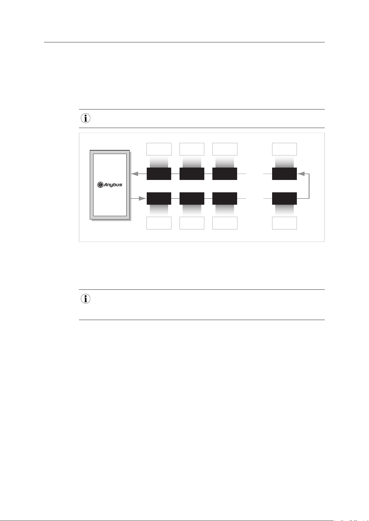
Shift Register Host Communication 41 (176)
INPUT SHIFT
REGISTER 32
Input Byte 31Input Byte n-1
Output Byte 31Output Byte n-1
OUTPUT SHIFT
REGISTER 32
INPUT SHIFT
REGISTER 1
INPUT SHIFT
REGISTER 2
INPUT SHIFT
REGISTER 3
OUTPUT SHIFT
REGISTER 1
OUTPUT SHIFT
REGISTER 2
OUTPUT SHIFT
REGISTER 3
INPUT SHIFT
REGISTER n
Input Byte 0
Input Byte 1 Input Byte 2
Output Byte 0 Output Byte 1 Output Byte 2
OUTPUT SHIFT
REGISTER n
7 Shift Register Host Communication
7.1 General Information
The Anybus CompactCom 40 can be used stand-alone, with no host processor. Process data is
communicated to shift registers on the host. The Anybus CompactCom 40 supports up to 32
registers in each direction, for a total of 256 bits of data.
The PROFIBUS version of the Anybus CompactCom 40 supports up to 24 registers in each direction, for a
total of 192 bits of data.
Fig. 14
The Anybus CompactCom 40 will automatically detect the number of connected input and
output shift registers. Every shift register will be represented by one UINT8 ADI. The input ADIs
will be named “Input 0”, “Input 1”, etc. The output ADIs will be named “Output 0”, “Output 1”,
etc.
The Anybus CompactCom 40 will always try to retrieve network specific attributes from a host
application. As this is not possible in stand-alone mode, a virtual attribute list, stored in
nonvolatile memory, will be used instead, see Anybus Object (01h), p. 62, section “Virtual
Attributes”. Some attributes are mandatory to implement in order to pass conformance tests,
see Conformance Test Information, p. 149
7.2 Reset
In stand-alone mode there is no application available to handle a reset request from the network.
The reset will be handled by the Anybus CompactCom 40 and the module will reset
automatically on a reset request from the network.
The ADI access descriptor values cannot be changed:
Input ADIs: 09h (Get access + Write process data mapping possible).
Output ADIs: 11h (Get access + Read process data mapping possible)
Anybus®CompactCom™40 Software Design Guide
HMSI-216-125 4.0 en-US
Page 44

Serial Host Communication (UART) 42 (176)
8 Serial Host Communication (UART)
8.1 General Information
This mode is supported for backward compatibility with the Anybus CompactCom 30, and should
not be used for pure Anybus CompactCom 40 applications.
On the serial host interface, telegrams are transmitted through a common asynchronous serial
interface. The baud rate is determined by certain signals on the host interface connector of the
module; consult the Anybus CompactCom 40 Hardware Design Guide for further information.
For more information on the serial host communication mode, please consult the Anybus
CompactCom 30 Software Design Guide.
Anybus®CompactCom™40 Software Design Guide
HMSI-216-125 4.0 en-US
Page 45

The Anybus State Machine 43 (176)
SETUP
(00h)
WAIT_PROCESS
(02h)
PROCESS_ACTIVE
(04h)
IDLE
(03h)
EXCEPTION
(07h)
(Power up)
(From all states)
ERROR
(05h)
NW_INIT
(01h)
9 The Anybus State Machine
9.1 General Information
A fundamental part of the Anybus CompactCom 40 is the Anybus State Machine. At any given
time, the state machine reflects the status of the module and the network, see Status Register
(Read Only), p. 33.
The state machine shall be regarded as a Moore machine; i.e. the host application is not required
to keep track of all state transitions, however it is expected to perform certain tasks in each state
Fig. 15
®
Anybus
CompactCom™40 Software Design Guide
HMSI-216-125 4.0 en-US
Page 46

The Anybus State Machine 44 (176)
9.2 State Dependent Actions
The expected actions for each state are listed below.
State
SETUP
NW_INIT
WAIT_PROCESS
IDLE
PROCESS_ACTIVE
ERROR
EXCEPTION
Description Expected Actions
Anybus CompactCom Setup in progress.
The module may not send commands to the
application in this state.
The Anybus CompactCom module is currently
performing network-related initialization
tasks.
Telegrams now contains Process Data (if such
data is mapped), however the network
Process Data channel is not yet active.
The network Process Data channel is
temporarily inactive.
The network interface is idle. The exact
interpretation of this state is network specific.
Depending on the network type, the Read
Process Data may be either updated or static
(unchanged).
The network Process Data channel is active
and error free.
There is at least one serious network error. The Read Process Data shall be regarded as
The module has ceased all network
participation due to a host application related
error.
This state is unrecoverable, i.e. the module
must be restarted in order to be able to
exchange network data.
See Anybus Setup (SETUP State), p. 59.
See Network Initialization (NW_INIT State), p.
60.
The host application shall regard the Read
Process Data as not valid.
The host application may act upon the Read
Process Data, or go to an idle state.
Perform normal data handling.
not valid. Optionally, the host application may
perform network specific actions.
Write Process Data could still be forwarded
to the master, so the application must keep
this data updated.
Correct the error if possible (details about the
error can be read from the Anybus Object,
see Anybus Object (01h), p. 62).
When done, reset the Anybus module.
The host application must keep the Write Process Data updated in NW_INIT (initial data),
WAIT_PROCESS, IDLE, ERROR and PROCESS_ACTIVE since this data is buffered by the
Anybus CompactCom, and may be sent to the network after a state shift.
See also ...
• Network Configuration Object (04h), p. 81
Anybus®CompactCom™40 Software Design Guide
HMSI-216-125 4.0 en-US
Page 47

Object Messaging 45 (176)
Host Application Anybus Module
Command 1
Response 1
Command 2
Command 3
Response 3
Response 2
10 Object Messaging
10.1 General Information
10.1.1 Basic Principles
Object messaging involves two types of messages; commands and responses. On the message
level, there is no master-slave relationship between the host application and the Anybus
CompactCom module; both parts may issue commands, and are required to respond. Commands
and responses are always associated with an instance within the Anybus object model. This can
either be the object itself (addressed through instance #0), or an instance within it.
Commands can be issued at any time (provided that the receiving end is ready to accept new
commands), while responses must only be sent as a reaction to a previously received command.
Unexpected or malformed responses must always be discarded.
Fig. 16
Commands and responses are treated asynchronously, i.e. new commands may be issued before
a response has been returned on the previous one. This also means that commands are not
guaranteed to be executed in order of arrival, and that responses may return in arbitrary order
Anybus®CompactCom™40 Software Design Guide
HMSI-216-125 4.0 en-US
Page 48

Object Messaging 46 (176)
(see figure). When necessary, the host application must wait for the response of any command
to which the action or result may affect successive commands.
10.1.2 Source ID
To keep track of which response that belongs to which command, each message is tagged with a
Source ID. When issuing commands, the host application may choose Source IDs arbitrarily,
however when responding to commands issued by the Anybus module, the Source ID in the
response must be copied from the original command.
10.1.3 Error Handling
When a command for some reason cannot be processed, the receiver is still obliged to provide a
response. In such case, an error shall be flagged in the header of the response message, together
with an appropriate error code in the message data field.
The command initiator must then examine the response to see whether it is a successful
response to the command or an error message.
See also...
• Error Codes, p. 52
10.2 Message Layout
An object message consists of an 12 byte header followed by message related data.
Contents
Offset
0 - 1 Message Data Size
2 - 3
4 Source ID See Source ID, p. 46
5
6
7
8 E
9
10
11
12...n
If the Anybus CompactCom 40 is used in a Anybus CompactCom 30 application, an 8 byte header
will have to be used. Please consult the Anybus CompactCom 30 Software Design Guide for
information.
b7 b6 b5 b4 b3 b2 b1 b0
(reserved)
Object
Instance (lsb)
Instance (msb)
C
Command Code See Command Codes, p. 51
(reserved)
CmdExt[0] Command-specific extension. See Command Specification, p. 51
CmdExt[1]
MsgData[0-n] Message data field
Description
Size of the MsgData[] field in bytes (up to 1524 bytes)
-
Specifies a source/destination within the Anybus Object model
Value: Meaning:
0: Message is either a Command, or a successful Response
1: Message is an Error Response
Value: Meaning:
0: Message is a Response 1: Message is a Command
-
These fields must be left intact in an error response.
10.3 Message Segmentation
The maximum message size supported by the Anybus CompactCom 40 is normally 1524 bytes. In
some applications a maximum message size of 255 bytes is supported, e.g. if an Anybus
CompactCom 40 is to replace an Anybus CompactCom 30 without any changes to the application.
Anybus®CompactCom™40 Software Design Guide
HMSI-216-125 4.0 en-US
Page 49

Object Messaging 47 (176)
Some objects services must support messages larger than 255 bytes. In order to support this, the
Anybus CompactCom 40 supports a fragmentation protocol. To avoid confusion with the
fragmentation protocol used for serial telegrams, this protocol is called a segmentation protocol.
10.3.1 Command Segmentation Procedure
When a message is segmented, the initiator of the message sends the same command header
multiple times. For each message, the data field is exchanged for the next segment of data.
Command Details
Command Segment Bits Description
CmdExt[1]
Response Details
CmdExt[1]
Bit 0:
Bit 1:
Bit 2:
Bit 3-7:
Response Segment Bits Description
Bit 0-7:
FS (first segment)
LS (last segment)
AB (abort)
Reserved (0)
Reserved (0)
Procedure
When sending segmented commands, follow the procedure below:
• For the first element, the FS bit shall be set.
• For the subsequent elements, the FS and LS bits shall be cleared (0).
• For the last element, the LS bit shall be set. (For single frame commands (<= 255 or 1524
bytes, depending on message channel) both the FS and the LS bits shall be set).
The command receiver shall send a response (ACK/NACK) for each segment, indicating if the
segment was accepted or not. In case of a NACK, the segment will be discarded. The
segmentation will not be terminated, however, so earlier accepted segments remain in the
segmentation buffer.
The response (ACK/NACK) to the last segment contains the actual result of the operation.
The command initiator may at any time abort the operation by sending a message with the AB
bit set. This shall result in that the segmentation buffer is flushed.
To determine if a command is the same as a previous one, the following shall be checked:
• Destination object
• Instance number
• Command number
• Command extension 0 (CmdExt[0])
10.3.2 Response Segmentation Procedure
When a response message is segmented, the initiator of the message requests the next segment
by sending the same command multiple times. For each message, the data field is exchanged for
the next segment of data.
Anybus®CompactCom™40 Software Design Guide
HMSI-216-125 4.0 en-US
Page 50

Object Messaging 48 (176)
Command Details
Command Segment Bits Description
CmdExt[1]
Bit 0:
Bit 1:
Bit 2:
Bit 3-7:
Reserved (0)
Reserved (0)
AB (abort)
Reserved (0)
Response Details
Response Segment Bits Description
CmdExt[1]
Bit 0:
Bit 1:
Bit 2-7:
FS (first segment)
LS (last segment)
Reserved (0)
Procedure
When sending segmented responses, follow the procedure below:
• For the first element, the FS bit shall be set.
• For the subsequent elements, the FS and LS bits shall be cleared (0).
• For the last element, the LS bit shall be set. (For single frame commands (<= 255 or 1524
bytes, depending on message channel) both the FS and the LS bits shall be set).
If the LS bit is not set in a response, the command initiator requests the next segment by sending
the same command again.
The command initiator may at any time abort the operation by sending a request/response with
the AB bit set. This shall result in that the segmentation buffer is flushed.
To determine if a command is the same as a previous one, the following shall be checked:
• Destination object
• Instance number
• Command number
• Command extension 0 (CmdExt[0])
Anybus®CompactCom™40 Software Design Guide
HMSI-216-125 4.0 en-US
Page 51

Object Messaging 49 (176)
10.4 Data Format
10.4.1 Available Data Types
The Anybus CompactCom 40 uses the following data types as standard. Additional network
specific data types are described in each separate network interface appendix (when applicable)
# Type
0 BOOL 8
1 SINT8 8
2 SINT16 16
3 SINT32 32
4 UINT8 8
5 UINT16 16
6 UINT32 32
7 CHAR 8 0... +255 Yes No
8 ENUM 8 0... +255 Yes Yes
9 BITS8 8
10 BITS16 16
11 BITS32 32
12 OCTET 8
13–15
16 SINT64 64
17 UINT64 64
18 FLOAT 32
19 DOUBLE 64
32–48 PADx 0-16
64 BOOL1 1
65–71 BITx 1-7
Bits Description
Boolean 0 = False, !0 = True
Signed 8 bit integer
Signed 16 bit integer
Signed 32 bit integer -2
Unsigned 8 bit integer
Unsigned 16 bit integer
Unsigned 32 bit integer 0... +(2
8 bit bit field
16 bit bit field
32 bit bit field
Undefined 8 bit data
(reserved)
Signed 64 bit integer -2
Unsigned 64 bit integer 0... +(2
Floating point (IEC 60559)
Floating point (IEC 60599)
Bit fields of size 0 - 16 used
for padding
1 bit boolean [0...1]
Bit fields of size 1-7 [0...1]... [0000000...1111111]
Range
-128... +127 Yes Yes
-32768...+32767 Yes Yes
31
... +(231-1)
0... +255 Yes Yes
0... +65535 Yes Yes
32
-1)
00000000... 11111111 Yes Yes
0000000000000000...
1111111111111111
00000000 00000000 00000000
00000000... 11111111 11111111
11111111 11111111
0... +255 Yes No
63
... +(263-1)
64
-1)
±1.17549435E-38...
±3.40282347E+38
±2.2250738585072014 E-308...
±1.7976931348623157 E+308
N/A
Available on
All Networks
Yes Yes
Yes Yes
Yes Yes
Yes Yes
Yes Yes
No Yes
No Yes
No Yes
No Yes
Yes Yes
Yes Yes
Yes Yes
Valid
for
Process
Data
• Arrays of type CHAR will be translated to the native string type of the network.
• The commands “Set_Indexed_Attribute” and “Get_Indexed_Attribute” cannot be used for
the data type CHAR .
• Data of type ENUM are enumerations, limited to a consecutive range of values starting at
zero.
• The data types BITS8, BITS16, BITS32, OCTET, PADx, BOOL1 and BITx are only supported by
Anybus CompactCom 40.
10.4.2 Bit Fields
The bit field types should be used for parameters where each bit, or group of bits, contains
individual meaning. Typical examples include control/status words or digital I/O.
Bit field parameters will be translated to network specific data types suitable for digital I/O or
control/status words.
Anybus®CompactCom™40 Software Design Guide
HMSI-216-125 4.0 en-US
Page 52

Object Messaging 50 (176)
BITSx
The BITSx data types (BITS8, BITS16, and BITS32) consist of even data byte sizes and must be
byte aligned. They are handled in the same way as other multibyte data types with regard to
byte order.
BITx
The BITx data types (BIT1-BIT7) are packed with bits aligned, and may be placed over byte
boundaries. The type code (65-71) of BITS1-BITS7 may be divided into the 5 most significant bits
as specifier (always 01000) and the 3 least significant bits as bit counter, with valid values from 1
to 7 for the bit counter field.
10.4.3 Handling of Array of Char (Strings)
Readable strings can be represented in ADIs in two different ways. Either as an array of CHAR or
as a string variable. The recommended way is to represent readable strings in ADIs as a variable
using the attribute “Number of subelements” in the Application Data Object (FEh), i.e. a string
variable that consists of one element with several subelements. This section is mainly applicable
when using arrays of CHAR in ADIs. Both these types of strings are hereafter named string.
Arrays of type CHAR will be translated to the native string type (when applicable). The maximum
string length, and the buffer space required to store it, is defined by the data type and the
number of elements.
All elements of an array of CHAR are significant; the Anybus module does not expect any
termination characters when reading, nor does it generate any when writing. The actual length
of the string is defined in the payload size given in the ‘Get_Attribute’- and ‘Set_Attribute’
commands.
Strings in ADI structures must be padded with NUL bytes up to the maximum length when
accessed through Set_Attribute and Get_Attribute. A get or set string with a data field size of
zero is valid and indicates an empty string.
Generally, it is recommended to keep the ‘number of elements’, ‘data type’, and the message
payload length, as consistent as possible. There is no guarantee that the Anybus CompactCom 40
will check consistency between the payload length and the actual buffer space.
See also...
• Application Data Object (FEh), p. 109
10.4.4 OCTET
The OCTET type is used for undefined data of byte size.
10.4.5 PADx
The PADx types consist of 17 types, from PAD0 to PAD16. PADx variables are packed with bit
alignment and might pass any byte boundaries. The value of a PADx variable is irrelevant and
might be skipped completely in a network specific way.
The type code (32-48) might be divided into the 3 most significant bits as specifier (always 001)
and the 5 least significant bits as bit counter, with valid values from 0 to 16 for the bit counter
field.
Anybus®CompactCom™40 Software Design Guide
HMSI-216-125 4.0 en-US
Page 53

Object Messaging 51 (176)
10.5 Command Specification
10.5.1 General Information
This chapter covers global commands, i.e. commands which have the same command code
regardless of which object that is being accessed.
Some objects have special requirements, which are handled through object-specific commands.
In such cases, unlike global commands, the same command code may have different meaning
depending on context (i.e. which object that is being accessed). Object-specific commands are
described separately for each object (when applicable).
See also...
• Anybus Module Objects, p. 61
• Host Application Objects, p. 105
Regarding generic command descriptions it should be noted that while a command has a defined
generic description and structure, the actual effect of it may differ greatly depending on the
context.
For example:
• Application issues Reset →Network Configuration Object = resets network settings
• Network Reset →Anybus issues Reset →Application Object = Anybus shifts to EXCEPTION
and awaits a hardware reset
Fields marked as reserved must be treated with caution. Reserved fields in messages sent
to the Anybus CompactCom must be set to 0 (zero), since they may have a defined use in
future Anybus revisions. In messages received from the Anybus CompactCom, reserved
fields shall simply be ignored.
10.5.2 Command Codes
The following commands are global, i.e. the same command code is used regardless of which
object that is being accessed. The commands are described in the subsections below.
Command Code Command Name
00h (reserved)
01h Get_Attribute
02h Set_Attribute
03h
04h Delete
05h
06h
07h Get_Indexed_Attribute
08h Set_Indexed_Attribute
09h... 0Fh (reserved)
10h... 30h (reserved for object specific commands)
31h... 3Eh (reserved)
3Fh (reserved for object specific commands)
Create
Reset
Get_Enum_String
®
Anybus
CompactCom™40 Software Design Guide
HMSI-216-125 4.0 en-US
Page 54

Object Messaging 52 (176)
10.5.3 Error Codes
If a command for some reason cannot be executed, the first byte in message data field (MsgData
[ ]) of the response is used to supply details about problem to the command initiator.
Normally use the first applicable error code from the table below, if more than one error code is relevant.
Additional object specific error information may also be added in the message data section.
Code Error
00h (reserved)
01h
02h Invalid message format Command and error bit set
03h Unsupported object Object not registered
04h Unsupported instance The target instance does not exist
05h Unsupported command The target object does not support the specified command
06h Invalid CmdExt[0] Invalid value of CmdExt[0] or invalid combination of CmdExt[0] and
07h Invalid CmdExt[1] Invalid setting in CmdExt[1]
08h Attribute not settable The requested attribute is not settable
09h Attribute not gettable The requested attribute is not gettable
0Ah Too much data Too much data in message data field
0Bh Not enough data Not enough data in message data field
0Ch Out of range A specified value is out of range Use this error code only when 11h or
0Dh Invalid state The command is not supported in the current state
0Eh Out of resources The target object cannot execute the command due to limited
0Fh Segmentation failure Invalid handling of the segmentation protocol
10h Segmentation buffer overflow Too much data received
11h Value too high The written data is too high
12h Value too low The written data is too low
13h Attribute controlled from
another channel
14h Message channel to small
15h General error An error not matching any of the other existing error codes has
16h Protected access Read or write operation could not be performed because access is
17h No data available The data source does not currently have a value available
18h... FEh (reserved)
FFh Object specific error The object returned an object specific error code. Additional details
Meaning
-
CmdExt[1]
12h cannot be used
resources
Used to NAK writes to “read process data” mapped attributes.
The message read/write area in use by the host application, does not
support a message channel with large enough data field to fit the
response data.
occurred.
currently protected by the host application.
-
may or may not be included in the message data field (MsgData[0...
n])
Error codes 11h - 17h are only available for Anybus CompactCom 40 devices.
Anybus®CompactCom™40 Software Design Guide
HMSI-216-125 4.0 en-US
Page 55

Object Messaging 53 (176)
10.5.4 Get_Attribute
Details
Command Code: 01h
Valid For: (depends on context)
Description
This command retrieves the value of an attribute. The attribute number must be left intact in an
error response.
• Command details:
Field
CMDExt[0] Attribute number
CMDExt[1] (reserved)
• Response details:
Field
MsgData[0..n] Attribute Value
10.5.5 Set_Attribute
Details
Command Code: 02h
Valid For: (depends on context)
Description
This command assigns a value to an attribute. The attribute number must be left intact in an
error response
• Command details:
Field
CMDExt[0] Attribute number
CMDExt[1] (reserved)
MsgData[0..n] Attribute Value
Contents
Contents
Contents
• Response details:
(No data)
Anybus®CompactCom™40 Software Design Guide
HMSI-216-125 4.0 en-US
Page 56

Object Messaging 54 (176)
10.5.6 Create
Details
Command Code: 03h
Valid For: Object Instance (Instance #0)
Description
This command creates a new instance within the object. If successful, the data portion of the
response contains the number of the newly created instance.
• Command details:
Object Specific
Not all objects have any specific details for this command. If there are any object specific
details, they are found in the description of the object in question.
• Response details:
Field
MsgData[0] The number of the created Instance (low byte)
MsgData[1] The number of the created Instance (high byte)
10.5.7 Delete
Details
Command Code: 04h
Valid For: Object Instance (Instance #0)
Description
This command deletes a previously created instance (see above). If successful, all resources
occupied by the specified instance will be released.
• Command details:
Field
CMDExt[0] Instance number to delete (low byte)
CMDExt[1] Instance number to delete (high byte)
• Response details (Success):
Contents
Contents
(No data)
• Response details (Error):
Field
Invalid CMDExt[0] The specified instance does not exist.
®
Anybus
CompactCom™40 Software Design Guide
Contents
HMSI-216-125 4.0 en-US
Page 57

Object Messaging 55 (176)
10.5.8 Reset
Details
Command Code: 05h
Valid For: (depends on context)
Description
This command performs a reset command on an object.
• Command details:
Field
CMDExt[0] (reserved)
CMDExt[1] 00h = Power-on reset (actual power-on or simulated)
• Response details:
(No data)
10.5.9 Get_Enum_String
Details
Command Code: 06h
Valid For: (depends on context)
Description
This command retrieves attributes which are of enumeration type (ENUM). The returned value is
the literal string associated with the specified enumeration value.
• Command details:
Field
CMDExt[0] The number of the attribute
CMDExt[1] The enumeration value
Contents
01h = Factory default reset
02h = Power-on + Factory default reset
Contents
• Response details (Success):
Field
MsgData[0..n] The enumeration string.
• Response details (Error):
Field
Invalid CMDExt[0..n] The enumeration value is out of range.
®
Anybus
CompactCom™40 Software Design Guide
Contents
Contents
HMSI-216-125 4.0 en-US
Page 58

Object Messaging 56 (176)
10.5.10 Get_Indexed_Attribute
Details
Command Code: 07h
Valid For: (depends on context)
Description
This command retrieves the value of a single element of an attribute which consists of multiple
elements (i.e. an array). Note that this command cannot be used to access attributes of type
CHAR.
• Command details:
Field
CMDExt[0] The number of the attribute
CMDExt[1] Index (first element has index 0)
• Response details (Success):
Field
MsgData[0..n] Value
• Response details (Error):
Field
Invalid CMDExt[0..n] Index is out of range
10.5.11 Set_Indexed_Attribute
Details
Command Code: 08h
Valid For: (depends on context)
Description
This command assigns a value to a single element of an attribute which consists of multiple
elements (i.e. an array). Note that this command cannot be used to access attributes of type
CHAR.
Contents
Contents
Contents
• Command details:
Field
CMDExt[0] The number of the attribute
CMDExt[1] Index (first element has index 0)
MsgData[0...n] Value to set
• Response details (Success):
(No data)
• Response details (Error):
Field
Invalid CMDExt[1] Index is out of range
®
Anybus
CompactCom™40 Software Design Guide
Contents
Contents
HMSI-216-125 4.0 en-US
Page 59

Initialization and Startup 57 (176)
11 Initialization and Startup
11.1 General Information
Before network participation, the following steps must be completed:
1. Startup Procedure
The purpose of the startup procedure is to make sure that both parts (the host application
and the Anybus CompactCom module) are ready to communicate. Normally an Anybus
CompactCom module is ready to communicate in less than 1.5 s. The module will then enter
the state SETUP. For more information, see Startup Procedure, p. 57.
2. Anybus CompactCom Setup
This step determines how the module shall operate. When done, the module will enter the
state NW_INIT.
For more information, see Anybus Setup (SETUP State), p. 59.
3. Network Initialization
At this stage, the module will attempt to read and evaluate information from the host
application. When finished, the module will enter the state WAIT_PROCESS.
For more information, see Network Initialization (NW_INIT State), p. 60.
When the module is restarted after a firmware download, the application must wait for
the upgrade to finish, before anything else is done, see below.
11.2 Startup Procedure
The startup procedure is slightly different depending on which type of host interface that is used,
but will normally be finished within 1.5 s.
1. Enable power.
2. Release reset to the module.
3. Wait for the Anybus CompactCom 40 to respond. Depending on interface, the expected
response is different:
Interface Expected Response
Parallel Host (8/16 bit)
SPI
Shift Register The Anybus CompactCom 40 module initializes autonomously after reset is released.
Serial Host This interface is backwards compatible to the Anybus CompactCom 30-series serial
The host application shall wait for the Anybus CompactCom interrupt signal to go
active, before starting to communicate.
After releasing the reset signal to the Anybus CompactCom module, the host
application may optionally wait for the Anybus CompactCom interrupt signal to go
active, thus indicating that the module is ready, before starting SPI communication.
The other option for the host application is to start SPI communication immediately
after releasing the Anybus CompactCom reset signal. The host application may see
SPI telegrams with CRC errors at first. These telegrams shall be retransmitted
according to normal error handling rules for the SPI protocol, see SPI Error Handling,
p. 39.
host interface. Please refer to the Anybus CompactCom 30 Software Design Guide
for information.
11.2.1 Suggested Startup Procedure when Upgrading from Network
To allow firmware upgrade from network, implement attribute #5 of the Application Object
(FFh), instance #1. The module will inform the host application when a new firmware candidate
Anybus®CompactCom™40 Software Design Guide
HMSI-216-125 4.0 en-US
Page 60

Initialization and Startup 58 (176)
is available in the candidate area. The host application must store the information in non-volatile
memory. See Application Object (FFh), p. 118.
If firmware upgrade from network is allowed, the following startup procedure is suggested:
Do not reset the Anybus CompactCom module during the startup procedure.
1. Enable power.
2. Release reset to the module.
3. Wait for the Anybus CompactCom 40 to respond. Depending on interface the expected
response is different:
Interface Expected Response
Parallel Host (8/16 bit)
SPI
Shift Register
Serial Host First serial telegram without CRC error
Interrupt
First SPI telegram without CRC error, or an active interrupt signal
N/A
4. If a new firmware candidate is available, the module will start to reprogram the firmware.
This can need up to 1 min. If no candidate firmware is available the boot time will always be
less than 1.5 seconds. In case of a firmware update, do not reset the module. If possible,
display a message to the end user: “Waiting for Anybus module”....
5. When a response is detected: Start the initialization of theAnybus CompactCom 40 module.
Remove any previously displayed message.
If the module does not respond as described, it has not started up correctly. Please contact HMS
Industrial Networks at www.anybus.com/support.
When the Anybus CompactCom 40 is reset after a firmware download, the application
must wait for the installation to finish, before initialization is started. The Anybus
CompactCom is protected against problems occurring during download and/or
installation and will recover upon restart.
To install the new firmware after download, reset the Anybus CompactCom 40. If the
installation of the new firmware is interrupted, e.g. due to power loss, please restart the
Anybus CompactCom 40. The installation process will automatically start from the
beginning and the new firmware will be installed without any further action.
Anybus®CompactCom™40 Software Design Guide
HMSI-216-125 4.0 en-US
Page 61

Initialization and Startup 59 (176)
11.3 Anybus Setup (SETUP State)
This stage involves four distinctive steps:
1. Gather information about the Anybus Module (Optional)
The host application may retrieve the network type, as well as other properties that may be
relevant when configuring the module, from the Anybus Object (01h). This information may
also be used to select different implementations based on e.g. the module type value.
2. Network Configuration (Optional)
At this stage, the host application should update all instances in the Network Configuration
Object of which the value originates from physical switches (i.e. node address, baud rate
etc.). Settings which originate from “soft” input devices such as a keypad and display should
not be updated at this point.
3. Process Data Mapping (Optional)
The host application may optionally map ADIs to Process Data.
This step is optional, but may be required by some networking systems and/or Anybus
implementations.
Certain Anybus implementations may attempt to alter the Process Data map during runtime.
For more information, see Application Data Object (FEh), p. 109.
4. Finalize the Setup
The setup procedure is finalized by setting the attribute Setup Complete in the Anybus
Object (01h) to TRUE.
If successful, the module now shifts to the state NW_INIT (below), or in case of failure, to
the state EXCEPTION. In case of the latter, further information can then be read from the
attribute Exception in the Anybus Object (01h).
See also..
• Network Data Exchange, p. 15
• The Anybus State Machine, p. 43
• Anybus Object (01h), p. 62
• Network Configuration Object (04h), p. 81
Anybus®CompactCom™40 Software Design Guide
HMSI-216-125 4.0 en-US
Page 62

Initialization and Startup 60 (176)
11.4 Network Initialization (NW_INIT State)
At this stage, the Anybus module will attempt to read and evaluate information from the host
application. The host application is required to respond to incoming requests to Host Application
Objects. If the requested object or attribute is not implemented in the host application, simply
respond with an error message. The module will in those cases use its own default values for the
requested attributes, or configured virtual attributes.
The host application is free to update any instances in the Network Configuration Object,
including those that do not originate from physical switches.
If a serious error is encountered (i.e. any error which prevents the module from proceeding) in
this state, the module will shift to the state EXCEPTION. Further information can then be read
from the attribute Exception in the Anybus Object (01h).
When done, the module enters the state WAIT_PROCESS.
The transition to this state is critical, especially if using the serial host interface, since
telegrams from this point may (depending on the setup) contain Process Data. It is
important to keep Write Process Data updated in this state since this data is buffered by
the module and may be sent to the network on the next state transition.
See also..
• The Anybus State Machine, p. 43
• Network Configuration Object (04h), p. 81
Anybus®CompactCom™40 Software Design Guide
HMSI-216-125 4.0 en-US
Page 63

Anybus Module Objects 61 (176)
12 Anybus Module Objects
12.1 General Information
The objects in this chapter are implemented as standard in all Anybus CompactCom
implementations. Their functionality is categorized to indicate when and how to use the objects.
Network specific Anybus module objects are described in the respective network guides. An
overview is shown in Object Overview, p. 147.
See also..
• Message Segmentation, p. 46
• Error Codes, p. 52
• Categorization of Functionality, p. 141
For detailed information about each object, see...
• Anybus Object (01h), p. 62
• Diagnostic Object (02h), p. 69
• Network Object (03h), p. 74
• Network Configuration Object (04h), p. 81
• Anybus File System Interface Object (0Ah), p. 83
• Functional Safety Module Object (11h), p. 98
12.2 Object Revisions
The purpose of the Object Revision attribute is to make it possible for the host application to
determine if the revision of the object in the Anybus module is compatible with the software
implementation in the host application, and/or to make it possible to choose different
implementations based on the object revision.
As a general rule, the object revision is updated when the object is changed in such a way that
the change may cause compatibility issues in the host application software implementation.
Minor changes, such as when an attribute or command has been added, are normally not cause
for a revision change.
Anybus®CompactCom™40 Software Design Guide
HMSI-216-125 4.0 en-US
Page 64

Anybus Module Objects 62 (176)
12.3 Anybus Object (01h)
Category
Basic
Object Description
This object assembles data about the Anybus CompactCom module itself. The data in question does not as
such represent the industrial network the module is adapted to, but describes data inherent to the module.
This data is available for use in the application. The values may differ, depending on industrial network, and are
in that case described in the respective appendices.
Most attributes in this object have access type “get” where data can be fetched using the command Get_
Attribute. The only attribute that is mandatory to set is “Setup complete” (instance #1, attribute #5), which is
used by the application to notify the module that it has finished the setup. If the configuration is not accepted,
the module will shift to the state EXCEPTION, and information can be read from instance #1, attribute #6
(“Exception Code”).
Supported Commands
Object: Get_Attribute (01h)
Reset (05h)
Instance:
Get_Attribute (01h)
Set_Attribute (02h)
Get_Enum_String (06h)
Object Attributes (Instance #0)
# Name Access Data Type
1 Name Get
2 Revision Get UINT8
3
Number of instances
4
Highest instance no.
Get UINT16
Get UINT16
Array of CHAR “Anybus”
Instance Attributes (Instance #1)
# Name Access Data Type
1
Module Type
2 Firmware version Get
3
Serial number
Get UINT16
struct of:
UINT8 Major
UINT8 Minor
UINT8 Build
Get UINT32
Value
04h
0001h
0001h
Description
Value:
0401h: Standard Anybus CompactCom 30
0402h: Anybus CompactCom Drive Profile 30
0403h: Standard Anybus CompactCom 40
0404h: Anybus IP
(Other) (reserved for future products)
Firmware version. Note that this value shall generally not be used to
determine if a particular functionality is available or not. Please use
the attribute Revision of each individual object for this purpose
Unique serial number
Meaning:
®
Anybus
CompactCom™40 Software Design Guide
HMSI-216-125 4.0 en-US
Page 65

Anybus Module Objects 63 (176)
# Name Access Data Type
4
Application watchdog
Get/Set
UINT16
timeout
5
Setup complete
6
Exception code
7 FATAL event
Get/Set
Get ENUM
Get/Set
BOOL
struct of: (HMS
Specific)
8 Error Counters Get
struct of: Error counters (stops counting at FFFFh).
UINT16 DC DC:
UINT16 DR DR:
UINT16 SE SE:
UINT16 FE FE:
9 Language
10
Provider ID
11
Provider specific info
Get/Set
Get UINT16
Get/Set
ENUM
UINT16
Description
Application watchdog configuration
Value:
0:
(other):
Meaning:
Disabled (default)
Timeout value (ms)
If enabled, the watchdog timeout time is active immediately,
regardless of the state of the application. The internal timer is
reloaded every time it is restarted, so the value of this attribute can
be changed during runtime.
If the timeout value is exceeded, the Anybus CompactCom 40 will
enter the state EXCEPTION with exception code 01h.
This attribute shall be set to TRUE when the Anybus Setup stage has
been completed. If the configuration is accepted, the Anybus module
shifts to the state NW_INIT. If not, i.e. if a serious error is detected in
the configuration, the module will shift to the state EXCEPTION. In
such case further information can be read from the attribute
Exception Code (below)
See also...
Anybus Setup (SETUP State), p. 59
See Exception Codes below.
The latest FATAL event (if any) is logged to this instance. Used for
evaluation by HMS support.
(The contents of this attribute is only used as input to HMS support
during application development)
(The contents of this attribute is only used during application
development.)
Discarded commands (received with R = 0)
Discarded (unexpected) responses
Serial reception errors
Fragmentation errors
Current language:
Value:
00h:
01h:
02h:
03h:
04h:
Enumeration String:
“English” (default)
“Deutsch”
“Español”
“Italiano”
“Français”
See also...
Application Object (FFh), p. 118 , including details for command
Change_Language_request.
Preprogrammed and stored permanently in FLASH by HMS during
production (contact HMS for further information).
Value:
0001h:
FFFFh:
Other:
Meaning:
HMS Networks
(reserved)
Provider specific
The information stored in this attribute is provider-specific, i.e. it has
no predefined meaning and is not evaluated nor used by the Anybus
module.
Any value written to this attribute will be stored in nonvolatile
memory. Default value is 0000h.
®
Anybus
CompactCom™40 Software Design Guide
HMSI-216-125 4.0 en-US
Page 66

Anybus Module Objects 64 (176)
# Name Access Data Type
12
LED colors
13 LED status Get UINT8
14
Switch status
15
(not used for Anybus
CompactCom 40)
16
GPIO configuration
Get
Get
- - -
Get/Set
struct of:
UINT8 LED1A
UINT8 LED1B
UINT8 LED2A
UINT8 LED2B
struct of
UINT8 SW1
UINT8 SW2
UINT16
Description
This attributes specifies the colors of the network status LEDs. See
Anybus CompactCom M40 Hardware Design Guide for more
information.
Value:
00h:
01h:
02h:
03h:
04h:
05h:
06h:
Bit field holding the current state of the network status LEDs as
follows:
Bit:
b0:
b1:
b2:
b3:
b4:
b5:
b6:
b7:
Values of DIP switches representing node address and baud rate,
connected to DIP pins in the host connector, see Anybus
CompactCom M40 Hardware Design Guide or Anybus CompactCom
B40 Design Guide.
Supported in serial, SPI and shift register mode. in other modes the
attribute contains random data.
This attribute is only supported on Anybus CompactCom 40.
Configuration of the host interface GPIO pins.
Set access is only valid during SETUP state.
Code:
0000h, GIP[0..1] are used as general input pins.
0001h: Extended LED functionality (default):
0002h:
0003h Three-state:
Meaning:
None (not used)
Green
Red
Yellow
Orange
Blue
White
Contents:
LED1A status (0=OFF, 1=ON)
LED1B status (0=OFF, 1=ON)
LED2A status (0=OFF, 1=ON)
LED2B status (0=OFF, 1=ON)
LED3A status (0=OFF, 1=ON)
LED3B status (0=OFF, 1=ON)
LED4A status (0=OFF, 1=ON)
LED4B status (0=OFF, 1=ON)
Description
GOP[0..1] are used as general output pins.
For the Anybus CompactCom 40 this mode is identical
to the Extended LED functionality (0001h) mode
GIP[0..1] are used as network specific, active low LED
outputs associated with the left, or single, port.
GOP[0..1] are used as network specific, active low LED
outputs associated with the right port.
RMII: GIP[0..1], /GOP[0..1], LED1A, LED1B, LED2A, and
LED2B are used to create RMII interface against the
application. Only valid for modules supporting RMII,
Please note that this code is not valid when running in
16 bit parallel mode.
GIP[0..1] and GOP[0..1] are set to three-state.
Anybus®CompactCom™40 Software Design Guide
HMSI-216-125 4.0 en-US
Page 67

Anybus Module Objects 65 (176)
# Name Access Data Type
17
Virtual attributes
18
Black list/White list Get/Set This attribute is used to implement the black list/white list.
19
Network time
20 Firmware custom
version
21
Anybus IP License
Get/Set
Get UINT64
Get UINT8
Get UINT8
Array of UINT8 This attribute is used to implement virtual host application attributes
struct of:
UINT8 InfoBits
UINT8 ListLen ListLen:
UINT16 Prot#1
UINT16 Prot#2
...
UINT16 Prot#n
Description
in the module, e.g. when using the module stand-alone.
This attribute is only supported on Anybus CompactCom 40.
Set access is only valid during SETUP state.
Maximum size: 1524 bytes. Stored in nonvolatile memory.
See “Virtual Attributes” below.
See“ Black List / White List” below..
This attribute is only supported on Anybus CompactCom 40.
Format:
InfoBits:
bit 0:
bit 1 - 7:
Prot#:
The current network time.
The format of the network time is specific to each network.
0 = the network does not support network time.
Note: This attribute is not supported by all networks. Consult the
network guides for more information.
This attribute is only supported on Anybus CompactCom 40.
This attribute holds a firmware version prefix, indicating a special
branch of the firmware.
Information about what license chip detected by Anybus IP. See
below for values.
Only supported on the Anybus IP platform.
0 = black list
1 = white list
reserved
Length of the list, equal to #n entries (Prot#n)
0 = List disabled
The network type identifier
Virtual Attributes
The virtual attributes list is a 1524 bytes array, stored in nonvolatile memory. The attributes are created using
the format below:
Object (8 bit)
Instance (16 bit)
Attribute (8 bit)
Length (16 bit)
Data (Length * 8 bit)
The virtual attributes are accessed via attribute #17 in the Anybus object.
When the Anybus CompactCom 40 tries to retrieve network specific attributes from the host application and
the application cannot supply these attributes, an error code is returned. The module will then check for the
missing attributes in the virtual attributes list. Please note that the attribute number has to be left intact in the
error response, or the requested attribute can not be found in the list.
Using the virtual attributes list, it is possible to provide network specific objects and/or attributes to the
module without implementing them in the host application. This may e.g. be useful when an application is to
be adapted to new networks, and need to support network specific attributes, that are not available in the
original application. Some attributes are mandatory in order to pass conformance tests, see Conformance Test
Information, p. 149.
If the array data in the virtual attributes list does not fit into a single message, a Get_Attribute request will
return the error code “Messaging channel too small” (14h).
Anybus®CompactCom™40 Software Design Guide
HMSI-216-125 4.0 en-US
Page 68

Anybus Module Objects 66 (176)
If the Anybus CompactCom 40 is used in stand-alone mode, no host application is available and the Anybus
CompactCom 40 will check for attributes in the virtual attributes list. The virtual attributes can only be set
before the “Setup complete” attribute is set.
If you change the module’s identity when implementing a stand-alone shift register solution, it is
necessary to implement the virtual attributes.
Black List / White List
Using the black list/white list, it is possible for the host to block or accept certain network types.
Bit 0 in the header of the list decides if it is a black list or a white list. If configured as a white list, only the
network types in the list will be accepted. If configured as a black list, all network types in the list will be
rejected.
A white list makes it possible to accept only a predefined choice of network types.
A black list makes it possible to block already defined network types.
The black list/white list is accessed via attribute #18 in the Anybus object.
Network type Network
0005h
0025h
0087h EtherCAT
0089h
0090h CC-Link
0093h Modbus TCP
009Bh
009Dh PROFINET IRT Fiber Optic
009Eh CC-Link IE Field
009Fh Ethernet POWERLINK
00A3h Common Ethernet
PROFIBUS DP-V1
DeviceNet
PROFINET IRT
EtherNet/IP
Anybus IP license
Code
0x00 None
0x01
0x02
0x03
See also...
• The Anybus State Machine, p. 43
License Description
Time bomb The security chip is not mounted or something went wrong when probing or
Standard Anybus IP is running with limited functionality.
Extended Full functionality enabled.
The security chip has not been probed yet.
reading from the security chip. Full functionality of Anybus IP is enabled but the
module only functional for a limited amount of time.
Anybus®CompactCom™40 Software Design Guide
HMSI-216-125 4.0 en-US
Page 69

Anybus Module Objects 67 (176)
Command Details: Reset
Details
Command Code 05h
Valid for: Object Instance
Description
This command is sent from the host application to the Anybus object (instance 0). A power-on reset is a
request to make the module ready for a power-on reset from the host application. A power-on + factory
default reset is a request a to return the module to the application specific out-of-box state and then make the
module ready for a power-on reset from the host application.
A power-on reset shuts down the network and then sets the module in the EXCEPTION state waiting for the
host to perform the power-on reset. Note that this command does not clear or reset any functionality stored in
non-volatile memory. No command data shall be supplied together with this reset type of reset command.
A power-on + factory default request shuts down the network, resets the functionality specified by the bit field
in the command data, reports the result in the response data and then sets the module in EXCEPTION state
waiting for the host application to perform the power-on reset.
If a power-on + factory default reset is successful the response bit field equals the command bit field, meaning
that all the targeted functionality was supported and reset successfully.
• Command details:
Field
CMDExt[0] (reserved)
CMDExt[1] 00h: Power-on reset (actual power-on or simulated)
Data[0-3] Bitmask specifying what to reset to factory default state (UINT32)
Contents
01h: (reserved)
02h: Power-on + Factory default reset
Bit(s):
0:
1:
2:
3-23
24-31
Description:
Network configuration parameters
Anybus file system
User created accounts and certificates
(reserved)
Reserved or network specific
• Response details:
Field
Data[0-3] Bitmask specifying what the Anybus CompactCom was supported to reset. See command data for bit
Contents
specification.
Exception Codes
When in the state EXCEPTION, this attribute provides additional information.
#
00h
01h Application timeout The host application has not responded within the specified watchdog timeout
02h Invalid device address The selected device address is not valid for the actual network.
03h Invalid communication settings The selected communication settings are not valid for the actual network.
Anybus
Enumeration String Description
No exception
®
CompactCom™40 Software Design Guide
-
period.
HMSI-216-125 4.0 en-US
Page 70

Anybus Module Objects 68 (176)
#
04h Major unrecoverable app event The host application has reported a major unrecoverable event to the Diagnostic
05h Wait for reset The module is waiting for the host application to execute a reset.
06h Invalid process data config The Process Data configuration is invalid.
07h Invalid application response The host application has provided an invalid response to a command.
08h Nonvolatile memory checksum error At least one of the parameters stored in nonvolatile memory has been restored
09h
0Ah Insufficient application implementation The application does not implement the functionality required for the Anybus
0Bh Missing serial number The module is missing a serial number. This might happen in product
0Ch Corrupt file system The file system is corrupt and must be formatted by user.
(other) (reserved)
Enumeration String Description
object.
to its default value due to a checksum error.
ASM communication error
Communication is lost between the Anybus CompactCom module and the
attached Anybus safety module.
module to continue its operation.
configurations which does not have an embedded serial number (e.g. Anybus
IP), and the application fails to supply one.
-
See also...
• The Anybus State Machine, p. 43
Object Specific Error Codes
The following object-specific error codes may be returned by the module as a response to setting the attribute
Setup complete.
# Error
01h Invalid process data configuration The Process Data configuration is invalid
02h Invalid device address The selected device address is not valid for the actual network
03h Invalid communication settings The selected communication settings are not valid for the actual network
Description
®
Anybus
CompactCom™40 Software Design Guide
HMSI-216-125 4.0 en-US
Page 71

Anybus Module Objects 69 (176)
12.4 Diagnostic Object (02h)
Category
Specific to each industrial network, see network guides.
Object Description
This object provides a standardized way of reporting diagnostic events to the network. Exactly how this is
represented on the network differs, however common to all implementations is that the module enters the
state EXCEPTION in case of a major unrecoverable event.
When the module has been started and initialized, no instances exist in the module. When a diagnostic event,
e.g. a blown fuse, occurs in the application, the application creates an instance with information on severity
and kind of event. The information in this instance remains available for the application, until the application
deletes the instance. The event code in the instance is processed by the module, to transfer correct networkspecific information about the event to the network used.
Supported Commands
Object: Get Attribute (01h)
Create (03h)
Delete (04)
Instance:
Get Attribute (01h)
Object Attributes (Instance #0)
# Name Access Data Type
1 Name Get
2 Revision Get UINT8
3
Number of instances
4
Highest instance no.
11
Max no. of instances
12
Supported functionality
Get UINT16
Get UINT16
Get UINT16
Get BITS32
Array of CHAR “Diagnostic”
Value
01h
(depends on number of created diagnostic events)
(network specific)
Max. no. of instances that can be created (network specific)
Of the maximum number of instances there should always be one
instance reserved for an event of severity level “Major,
unrecoverable”, to force the module into the state EXCEPTION.
Bit 0: “1” if latching events are supported
“0” if latching events are not supported
Bit 1 - 31: reserved (shall be “0”)
®
Anybus
CompactCom™40 Software Design Guide
HMSI-216-125 4.0 en-US
Page 72

Anybus Module Objects 70 (176)
Instance Attributes (Instance #1... N)
# Name Access Type
1 Severity Get UINT8
2
Event Code
3
NW specific extension
4
Slot
5 ADI Get UINT16
6
Element
7 Bit Get UINT8
Get UINT8
Get
Get UINT16
Get UINT8
Array of UINT8 Network specific event information (optional)
Description
This attribute should be viewed as a bit field
Bit 0 (the least significant bit) indicates whether extended
diagnostics are used by the instance
• Bit 0 = 1: extended diagnostics are used
• Bit 0 = 0: extended diagnostics are not used
Bits 4 - 6 are used for severity level information. See below.
See below.
Indicates which slot in a modular device the diagnostic event is
associated with
Default value: 0
For more information, see "Modular Device Object (ECh)" on page
125
Indicates which ADI the diagnostic event is associated with
Default value: 0 (if the diagnostic instance is not associated with any
particular ADI)
Indicates which element in the ADI the diagnostic event is
associated with
The value 255 is used if the diagnostic event is associated with the
entire ADI
Default value: 255
Indicates the bit in the element that the diagnostic event is
associated with
The value 255 is used to indicate that the diagnostic event is
associated with the entire element
Default value: 255
Severity
This parameter indicates the severity level of the event. Only bits 4 - 6 are used for severity level information.
Severity Levels
Bit Combination
000
001
010
011
101
110
(other)
Recoverable events shall be deleted by the application when the cause of the error is gone.
Unrecoverable events cannot be deleted. They remain active until the Anybus CompactCom is reset or power
is turned off.
Latching events remain active until explicitly acknowledged by the network master. If the network does not
support acknowledgment of latching diagnostic events, the module shall refuse the creation of latching
diagnostic events.
When the network master acknowledges one or more latching events, the module shall send a “Reset
Diagnostic” request to the application object. The request contains a list of diagnostic instances which the
master wishes to acknowledge. The application object shall respond with a list of diagnostic instances which it
allows the module to delete. The module will then delete the allowed instances, and report the appropriate
information to the network master.
Severity Comment
Minor, recoverable
Minor, unrecoverable Unrecoverable events cannot be deleted
Major, recoverable
Major, unrecoverable Causes a state-shift to EXCEPTION
Minor, latching
Major, latching
-
-
-
(reserved for future use)
Anybus®CompactCom™40 Software Design Guide
HMSI-216-125 4.0 en-US
Page 73

Anybus Module Objects 71 (176)
Event Codes
#
Meaning
Generic Error
10h
Current
20h
21h Current, device input side
22h Current, inside the device
23h Current, device output side
30h Voltage
31h Mains Voltage
32h Voltage inside the device
33h Output Voltage
Temperature
40h
41h Ambient Temperature
42h
50h Device Hardware
60h Device Software
61h Internal Software
62h User Software
63h
70h Additional Modules
80h
81h
82h Protocol Error
90h External Error
F0h Additional Functions
FFh NW specific Definition is network-specific; consult separate network guide for further
Device Temperature
Data Set
Monitoring
Communication
Comment
-
-
-
-
-
-
-
-
-
-
-
-
-
-
-
-
-
-
-
-
-
-
-
information.
®
Anybus
CompactCom™40 Software Design Guide
HMSI-216-125 4.0 en-US
Page 74

Anybus Module Objects 72 (176)
Command Details: Create
Details
Command Code: 03h
Valid For: Object
Description
Creates a new instance, in this case representing a new diagnostic event in the host application.
• Command details:
Field
CMDExt[0]
CMDExt[1] Event Code, see previous page
MsgData[0...1] Slot number associated with the event
MsgData[2...3] ADI associated with the event
MsgData[4] Element associated with the event
MsgData[5] Bit in element associated with the event
MsgData[6...7] Reserved. Set to zero
MsgData[0/8...n]
Contents Note
Bit 0:
Bit 4–6:
Other bits
Set to “0” if unknown or unsupported
Set to “0” if unknown or unsupported
Set to “255” if unknown or unsupported
Set to “255” if unknown or unsupported
Network specific extension (optional, definition is network
specific)
Extended Diagnostic
Severity
Reserved. Set to zero.
• Response details (Success):
Field
MsgData[0...1] The number of the instance that was created as a result from the command
Contents
• Response details (Error):
Error Contents Comment
Object Specific Error MsgData[1] = 02h Error code (Latching event not supported)
MsgData[1] = FFh Error code (Network specific error)
The event could not be created since the module does not support
latching events
The event could not be created due to a network specific reason.
Information about the event is found in response MsgData[2-n]
These fields only exist if bit 0 (Extended
Diagnostic) is set
MsgData[8...n] if bit 0 in CmdExt[0] is set
MsgData[0...n] if bit 0 in CmdExt[0] is not
set
®
Anybus
CompactCom™40 Software Design Guide
HMSI-216-125 4.0 en-US
Page 75

Anybus Module Objects 73 (176)
Command Details: Delete
Details
Command Code: 04h
Valid For: Object
Description
Deletes an existing instance, i.e. a previously created diagnostic event.
Instances representing unrecoverable events and latching events cannot be deleted.
• Command details:
Field
CMDExt[0] The number of the instance to delete (low byte)
CMDExt[1] The number of the instance to delete (high byte)
Contents
• Response details (Error):
Error Contents Comment
Object Specific Error MsgData[1] = 01h Error code (Not removed).
MsgData[1] = FFh Error code (Network specific error)
The event could not be removed, either because the event itself is
unrecoverable, latching, or due to a network specific reason.
The event could not be deleted due to a network specific reason
Information about the event is found in response MsgData[2-n]
See also:
– Error Codes, p. 52
Anybus®CompactCom™40 Software Design Guide
HMSI-216-125 4.0 en-US
Page 76

Anybus Module Objects 74 (176)
12.5 Network Object (03h)
Category
Basic
Object Description
This object holds general information about the network (i.e. network type, data format etc.). It is also used
when mapping ADIs as Process Data from the host application side.
See also...
• Functional Safety Object (E8h), p. 107
• Application Object (FFh), p. 118
Supported Commands
Object: Get_Attribute (01h)
Instance:
Get_Attribute (01h)
Set_Attribute (02h)
Get_Enum_String (06h)
Map_ADI_Write_Area (10h)
Map_ADI_Read_Area (11h)
Map_ADI_Write_Ext_Area (12h)
Map_ADI_Read_Ext_Area (13h)
Object Attributes (Instance #0)
# Name Access Data Type
1 Name Get
2 Revision Get UINT8
3
Number of instances
4
Highest instance no.
Get UINT16
Get UINT16
Array of CHAR “Network”
Value
02h
(Module type dependent)
(Module type dependent)
®
Anybus
CompactCom™40 Software Design Guide
HMSI-216-125 4.0 en-US
Page 77

Anybus Module Objects 75 (176)
Instance Attributes (Instance #1)
# Name Access Category Type
1
Network type
2
Network type string
3
Data format
4
Parameter data support
5 Write Process Data size Get
6
Read Process Data size
7
Exception Information
Network type Network Type String
0005h “PROFIBUS DP-V1”
0025h “DeviceNet”
0087h “EtherCAT”
0089h “PROFINET IRT”
0090h “CC-Link”
0093h “Modbus TCP”
009Bh
009Dh “PROFINET IRT Fiber Optic”
009Eh “CC-Link IE Field”
009Fh “Ethernet POWERLINK”
00A3h “Common Ethernet ”
Get
Get
Get Basic ENUM
Get
Get
Get
Extended
-
Extended
-
-
-
“EtherNet/IP”
UINT16
Array of CHAR
BOOL
UINT16
UINT16
UINT8
Description
(See separate Network Guide and/or table below)
Network data format:
Value:
00h:
01h:
This attribute indicates if the network supports acyclic
data services. It can also be used for deciding what
ADIs to map to Process Data.
Value:
True:
False:
The current write Process Data size (in bytes).
Updated on every successful Map_ADI_Write_Area,
Map_ADI_Write_Ext_Area, Remap_ADI_Write_Area or
any network specific mapping command.
The current read Process Data size (in bytes).
Updated on every successful Map_ADI_Read_Area,
Map_ADI_Read_Ext_Area, Remap_ADI_Read_Area or
any network specific mapping command.
Additional network specific information may be
presented here if the module has entered the
EXCEPTION state (see separate network guide).
Enumeration String:
“LSB First”
“MSB First”
Meaning:
Network supports acyclic data access
No support for acyclic data
®
Anybus
CompactCom™40 Software Design Guide
HMSI-216-125 4.0 en-US
Page 78

Anybus Module Objects 76 (176)
Command Details: Map_ADI_Write_Area
Details
Command Code: 10h
Valid For:
Instance
Description
This command maps an ADI as Write Process Data. If successful, the response data contains the offset of the
mapped ADI from the start of the Write Process Data image.
• It is strongly recommended not to map an ADI more than once (i.e. map it multiple times to the Read- or
Write Process Data, or map it to both the Read- and Write Process Data) since this is not accepted by
some networks.
• It is not possible to map only part of an ADI, i.e. all elements of an ADI must always be mapped.
• It is not allowed to mix mapping commands Map_ADI_Read/Write_Area and Map_ADI_Read/Write_Ext_
Area within one area.
• It is not allowed to map BITSx types of fractional byte size (BIT1 - BIT7) or PADx types using this command.
• It is only allowed to map variables and arrays with this command. It is not allowed to map structures.
• Certain Anybus implementations allow the network to remap the Process Data during runtime. For more
information, see Application Data Object (FEh), p. 109.
• To map more than 256 bytes, use the commands Map_ADI_Read/Write_Ext_Area.
• The commands Map_ADI_Read/Write_Area should only be used in applications that include one or more
Anybus CompactCom 30 devices. For new applications, including only Anybus CompactCom 40 devices,
use the commands Map_ADI_Read/Write_Ext_Area.
See also...
• Application Object (FFh), p. 118
Error control is only performed on the command parameters. The Anybus module does not verify the
correctness of these parameters by a read of the actual ADI attributes.
• Command details:
Field
CmdExt[0] Instance number of the ADI (low byte)
CmdExt[1] Instance number of the ADI (high byte)
MsgData[0] Data Type of the ADI, see Data Format, p. 49
MsgData[1] Number of elements in the ADI
MsgData[2] Order Number of the ADI (low byte)
MsgData[3] Order Number of the ADI (high byte)
Contents
The Order Number in the mapping command equals that of the command Get_Instance_Number_By_
Order the Application Data Object.
Anybus®CompactCom™40 Software Design Guide
HMSI-216-125 4.0 en-US
Page 79

Anybus Module Objects 77 (176)
• Response details (Success):
Field
MsgData[0] Offset of the mapped ADI from the start of the Write Process Data
Contents
• Response details (Error):
Error Contents
Invalid CmdExt[0] The ADI number is not valid.
Invalid State Mapping of ADIs is only allowed in the SETUP state
Object Specific Error Object specific error, see MsgData[1] for details:
01h: Invalid data type The data type is not valid for Process Data
02h: Invalid number of elements The number of elements is not valid (zero)
03h: Invalid total size The requested mapping is denied because the resulting total data
04h: Multiple mapping The requested mapping was denied because the specific network
05h: Invalid Order Number The order number is not valid (zero)
06h: Invalid map command
sequence
size would exceed the maximum permissible (depending on
network type)
does not accept multiple mapping of ADIs
The order in which the commands were received is invalid
Error control is only performed on the command parameters. The Anybus module does not verify the
correctness of these parameters by a read of the actual ADI attributes.
Command Details: Map_ADI_Read_Area
Details
Command Code: 11h
Valid For:
Instance
Description
This command is identical to Map_ADI_Write_Area, described above, except that it maps ADIs to Read Process
Data.
Anybus®CompactCom™40 Software Design Guide
HMSI-216-125 4.0 en-US
Page 80

Anybus Module Objects 78 (176)
Command Details: Map_ADI_Write_Ext_Area
Details
Command Code: 12h
Valid For:
Instance
Description
This command is only supported by Anybus CompactCom 40 devices.
This command is equivalent to Map_ADI_Write_Area, but can map more than 256 bytes of data. It supports
mapping fractional byte size types, and it can be used to map only specific parts of an ADI.
It maps an ADI as Write Process Data. If successful, the response data contains the offset, in bits, for the
mapped ADI from the start of the Write Process Data area.
• Mapping an ADI more than once (i.e. map it multiple times to the Read- or Write Process Data, or map it
to both the Read- and Write Process Data) is not accepted by all networks.
• It is not allowed to mix mapping commands Map_ADI_Read/Write_Area and Map_ADI_Read/Write_Ext_
Area within one area (Read/Write).
• It is recommended to only map one item for each mapping command during initial development, since
data area offset is only given for the first mapping item, and all mapping items may be rejected using one
single error code.
• All mapped elements, except those of types BIT1-BIT7 and PADx, must be byte aligned.
• The only implicit padding done is from the very last mapped item up to byte alignment, since the process
data needs to be of byte size when the setup is complete.
• Explicit padding is done either through available ADI elements of PADx type, or through the imaginary ADI
0, which is assumed to be an array with 255 elements of type PAD1. Explicit padding of process data is the
only correct use of ADI 0. Padding bits might not be visible on the network.
• This command may permanently alter the state of the Anybus CompactCom 40 even though the
command is returned with an error. Network specific restrictions may lead to n mapping items to be
accepted, but with an error on mapping item n+1. If so, the mappings up to and including n will be
accepted, but all other mapping items, starting with n+1, are rejected. The number of accepted mappings
is declared in CmdExt[ 0 ] of the answer.
• Certain Anybus implementations allow the network to remap the Process Data during runtime. For more
information, see Application Data Object (FEh), p. 109.
See also...
Application Object (FFh), p. 118
Error control is only performed on the command parameters. The Anybus module does not verify the
correctness of these parameters by a read of the actual ADI attributes.
Anybus®CompactCom™40 Software Design Guide
HMSI-216-125 4.0 en-US
Page 81

Anybus Module Objects 79 (176)
• Command details:
Field
CmdExt[0] The number of mapping items to add (0-217)
CmdExt[1] Reserved. Set to 0
MsgData[0-1] New mapping item 1: ADI number
MsgData[2] New mapping item 1: Number of elements in the ADI
MsgData[3] New mapping item 1: Index to the first element to map (0-254)
MsgData[4] New mapping item 1: Number of consecutive elements to map (1-255)
MsgData[5] New mapping item 1: Number of type descriptors (1-255)
MsgData[6..n] New mapping item 1: Array of type specifiers for each mapped element
...
Contents
Repeat MsgData[0-n] (as above) for mapping item 2 and onwards.
• Response details (Success):
Field
CmdExt[0] The number of accepted mapping items (0-217)
MsgData[0] Bit offset of the mapped ADI from the start of the Write Process Data (Least significant byte)
MsgData[1] Bit offset of the mapped ADI from the start of the Write Process Data
MsgData[2] Bit offset of the mapped ADI from the start of the Write Process Data
MsgData[3] Bit offset of the mapped ADI from the start of the Write Process Data (Most significant byte)
Contents
• Response details (Error):
Error Contents
Invalid CmdExt[0] The number of accepted mapping items, before an error occurred
Invalid State Mapping of ADIs is only allowed in the SETUP state
Object Specific Error Object specific error, see MsgData[1] for details:
01h: Invalid data type The data type is not valid for Process Data
02h: Invalid number of elements The number of elements is not valid (zero, or too many elements)
03h: Invalid total size The requested mapping is denied because the resulting total data
06h: Invalid map command
sequence
07h: Invalid mapping command Inconsistencies in the command makes it impossible to parse
08h: Bad alignment The alignment rules for process data are not followed
09h: Invalid use of ADI 0 ADI 0 is an array (255 elements) of type PAD1
FFh: Network specific restriction The mapping is denied because of a network specific reason,
size would exceed the maximum permissible (depending on
network type)
The order in which the commands were received is invalid
stated in response Data[2-n]. Consult the relevant network guide
Error control is only performed on the command parameters. The Anybus module does not verify the
correctness of these parameters by a read of the actual ADI attributes.
Anybus®CompactCom™40 Software Design Guide
HMSI-216-125 4.0 en-US
Page 82

Anybus Module Objects 80 (176)
Command Details: Map_ADI_Read_Ext_Area
Details
Command Code: 13h
Valid For:
Instance
Description
This command is only supported by Anybus CompactCom 40 devices.
This command is equivalent to Map_ADI_Read_Area, but can map more than 256 bytes of data.
It is identical to Map_ADI_Write_Ext_Area, described above, except that it maps ADIs to Read Process Data.
Anybus®CompactCom™40 Software Design Guide
HMSI-216-125 4.0 en-US
Page 83

Anybus Module Objects 81 (176)
12.6 Network Configuration Object (04h)
Category
Network specific
Object Description
This object contains network specific configuration parameters that may be set by the end user, typically
settings such as baud rate, node address etc. Although the actual definition of the instances in this object are
network specific, instance 1 and 2 are fixed (when possible).
When possible, the following convention is used for these instances:
Instance no. Data type Parameter
1
2
The instance values in this object must be updated whenever their originating value changes. Mechanical
switches or similar need therefore be continuously monitored by the host application.
• Instances tagged with ‘shared’ access (indicated by the descriptor) must be regarded as volatile; a ‘set’
access towards such an instance may or may not alter its value. The Anybus module will not respond with
an error in case the value remains unaffected.
Any 8 bit or 16 bit data type Currently selected network device address (or similar).
Any 8 bit or 16 bit data type Currently selected network communication bit rate (or similar).
• When a set request with 8 bits of data is directed to a 16 bit instance, the set request is accepted and the
upper 8 bits are set to zero.
• When a set request with 16 bits of data is directed to a 8 bit instance, the set request is accepted and the
upper 8 bits are discarded.
Differentiation of Input Devices
The Anybus module makes a distinction between parameters originating from “hardwired” input devices (i.e.
physical mechanical switches) and parameters specified using a “soft” input device such a keypad and display.
This permits the Anybus module to fulfill network specific needs related to the actual origin of a parameter (e.
g. some networks require that a change of value on physical switches is visually acknowledged on the on-board
LEDs).
This distinction is based on the following actions from the host application (see table).
State
SETUP
(other states) Poll and update all parameters (i.e.
Actions (Host Application) Anybus Behavior
Poll and update parameters
originating from physical switches
(make sure to issue at least one Set
command for each one of the
affected parameters). Do not update
parameters originating from “soft”
input devices (do not issue any Set
commands for these parameters yet).
physical switches and “soft” input
methods) as necessary.
The Anybus module identifies the affected parameters as originating from
physical switches. The remainder are assumed to originate from “soft” input
devices.
The Anybus module keeps track of the parameters which were updated during
the SETUP state, and is thus able to treat them differently if required by the
network.
®
Anybus
CompactCom™40 Software Design Guide
HMSI-216-125 4.0 en-US
Page 84

Anybus Module Objects 82 (176)
Supported Commands
Object: Get_Attribute (01h)
Reset (05h) (The actual behavior is network specific)
Instance:
Get_Attribute (01h)
Set_Attribute (02h)
Get_Enum_String (06h)
Object Attributes (Instance #0)
# Name Access Data Type
1 Name Get
2 Revision Get UINT8
3
Number of instances
4
Highest instance no.
Get UINT16
Get UINT16
Array of CHAR “Network Configuration”
Value
01h
(Network dependent)
(Network dependent)
Instance Attributes (Instance #1... n)
Each instance represents a network configuration parameter. The attributes within it provides a
comprehensive description of the parameter (name, data type etc.). Instance names and enumeration strings
are multilingual . The actual strings are of course network specific, but the maximum number of characters is
limited to thirteen (13).
# Name Access Category Type
1 Name Get
2 Data type Get
3
Number of elements
4 Descriptor Get
5
Value Determined
6
Configured value
Get
by attribute
#4
Get
Application
specific
Application
specific
Application
specific
Application
specific
Application
specific
Application
specific
Array of CHAR Parameter name (e.g. “Node address”)
UINT8 Data type, see Data Format, p. 49
UINT8
UINT8
Determined by
attribute #2
Determined by
attribute #2
Description
Number of elements of the specified data type
Bit field specifying the access rights for the parameter
Bit:
b0:
b1:
b2:
Actual parameter value. Stored in nonvolatile memory
Get access: the actually used value will be returned
Set access: the configured (and possibly the actual)
value will be written
The configured parameter value
Returns the configured value of an attribute. It is useful
when ‘Value’ is not being used directly when set, e.g.
when a power cycle is needed
Access:
1: Get Access
1: Set Access
1: Shared Access
Instances tagged with shared access must
be regarded as volatile; a Set-access
towards such an instance may or may not
alter its value. The Anybus module will
not respond with an error in case the
value remains unaffected.
Instance #1 and instance #2 are categorized as Basic, if they exist in an application. All other instances of this
object are categorized in the respective network guides.
Anybus®CompactCom™40 Software Design Guide
HMSI-216-125 4.0 en-US
Page 85

Anybus Module Objects 83 (176)
12.7 Anybus File System Interface Object (0Ah)
Category
Extended
Object Description
This object provides an interface to the built-in file system. Each instance represents a handle to a file stream
and contains services for file system operations. This provides the host application with access to the built-in
file system of the module. Instances are created and deleted dynamically during runtime.
The object is structurally almost identical to the Application File System Interface Object (EAh), see Application
File System Interface Object (EAh), p. 130.
Ethernet modules have a file system that is accessible to the application for different purposes, e.g. for firmware
download/upgrade and internal web pages. See the respective network guides for more information. For all other
modules, only one folder is present. This folder is only used for downloading and upgrading firmware.
Supported Commands
Object: Get_Attribute (01h)
Set_Attribute (02h)
Create (03h)
Delete (04h)
FormatDisc (30h)
Instance:
Get_Attribute (01h)
File Open (10h)
File Close (11h)
File Delete (12h)
File Copy (13h)
File Rename (14h)
File Read (15h)
File Write (16h)
Directory Open (20h)
Directory Close (21h)
Directory Delete (22h)
Directory Read (23h)
Directory Create (24h)
Directory Change (25h)
®
Anybus
CompactCom™40 Software Design Guide
HMSI-216-125 4.0 en-US
Page 86

Anybus Module Objects 84 (176)
Object Attributes (Instance #0)
# Name Access Data Type
1 Name Get
2 Revision Get UINT8
3
Number of instances
4
Highest instance no.
11
Max no. of instances
12
Disable virtual file
system
13
Total disc size
14
Free disc size
Get UINT16
Get UINT16
Get UINT16
Set BOOL
Get UINT32
Get UINT32
Array of CHAR “Anybus File System Interface”
Instance Attributes (Instance #1... 4)
# Name Access Category Type
1 Instance Type Get
2
File size
3
Path
Get
Get
Extended
Extended
Extended Array of CHAR The file path to where the instance operates
UINT8
UINT32
Value/Description
02h
-
-
4: valid for Anybus CompactCom 40 modules supporting IT
functionality.
1: valid for Anybus CompactCom 40 modules, not supporting
multiple open file/directory streams.
If the virtual file system is disabled it will not be possible to access
the internal web pages.
0 = the virtual file system is enabled (default)
1 = the virtual file system is disabled
Disc size in bytes.
Free disc size in bytes.
Description
Value:
0:
1:
2:
File size (0 for a directory)
Meaning:
Reserved
File instance
Directory instance
®
Anybus
CompactCom™40 Software Design Guide
HMSI-216-125 4.0 en-US
Page 87

Anybus Module Objects 85 (176)
File System Errors
In case of errors for services calling the file system interface object, the module will return FFh (object specific
error). A descriptive file system error will be returned in the error response data field.
# Name
1 FILE_OPEN_FAILED
2 FILE_CLOSE_FAILED
3 FILE_DELETE_FAILED
4 DIRECTORY_OPEN_FAILED
5 DIRECTORY_CLOSE_FAILED
6 DIRECTORY_CREATE_FAILED
7 DIRECTORY_DELETE_FAILED
8 DIRECTORY_CHANGE_FAILED
9 FILE_COPY_OPEN_READ_FAILED
10 FILE_COPY_OPEN_WRITE_FAILED
11 FILE_COPY_WRITE_FAILED
12 FILE_RENAME_FAILED
Description
Could not open file
Could not close file
Could not delete file
Could not open directory
Could not close directory
Could not create directory
Could not delete directory
Could not change directory
Could not open file for copy
Could not open file for destination
Could not write file when copying
Could not rename file
®
Anybus
CompactCom™40 Software Design Guide
HMSI-216-125 4.0 en-US
Page 88

Anybus Module Objects 86 (176)
Command Details: File Open
Details
Command Code: 10h
Valid for:
Instance
Description
Opens a file for reading, writing or appending.
• Command details:
Field
CmdExt[0] 00h - Read mode Opens a file for read only access.
CmdExt[1] (reserved, 0)
MsgData[0...n] Path + filename of the
Contents Comment
01h - Write mode Opens a file for write only access. If the specified file does not exist, it will be
created. If the specified file already exists, it will be overwritten.
02h - Append mode Opens a file for writing at end-of-file. If the specified file does not exist, it will
be created. If the specified file exists, any data written to the file will be
appended at end-of-file.
-
-
file to open relative to
current path
• Response details:
(No data)
Command Details: File Close
Details
Command Code: 11h
Valid for:
Instance
Description
Closes an open file.
• Command details:
(No data)
• Response details:
Field
CmdExt[0] Reserved (0)
CmdExt[1] Reserved (0)
MsgData[0] File size (low byte) The size of the closed file
MsgData[1] File size
MsgData[2] File size
MsgData[3] File size (high byte)
Contents Comment
-
-
®
Anybus
CompactCom™40 Software Design Guide
HMSI-216-125 4.0 en-US
Page 89

Anybus Module Objects 87 (176)
Command Details: File Delete
Details
Command Code: 12h
Valid for:
Instance
Description
Deletes the specified file.
• Command details:
Field
CmdExt[0] (reserved, 0)
CmdExt[1] (reserved, 0)
MsgData[0...n] Path + filename of the file to delete relative to current path
Contents
• Response details:
(No data)
Command Details: File Copy
Details
Command Code: 13h
Valid for:
Instance
Description
Makes a copy of a file.
• Command details:
Field
CmdExt[0] (reserved, 0)
CmdExt[1] (reserved, 0)
MsgData[0]... Path + filename of the source file, relative to the current path
MsgData[x] NULL (00h)
MsgData[y]... Path + filename of the destination file, relative to the current path
Contents
• Response details:
(No data)
Anybus®CompactCom™40 Software Design Guide
HMSI-216-125 4.0 en-US
Page 90

Anybus Module Objects 88 (176)
Command Details: File Rename
Details
Command Code: 14h
Valid for:
Instance
Description
Renames or moves a file.
• Command details:
Field
CmdExt[0] (reserved, 0)
CmdExt[1] (reserved, 0)
MsgData[0]... Old path + filename, relative to the current path
MsgData[x] NULL (00h)
MsgData[y]... New path + filename, relative to the current path
Contents
• Response details:
(No data)
Command Details: File Read
Details
Command Code: 15h
Valid for:
Instance
Description
Reads data from a file open for reading.
• Command details:
Field
CmdExt[0] The number of bytes to read (low byte)
CmdExt[1] The number of bytes to read (high byte)
Contents
• Response details:
Field
CmdExt[0] (reserved, 0)
CmdExt[1] (reserved, 0)
MsgData[0]... Data read from the file
Contents
®
Anybus
CompactCom™40 Software Design Guide
HMSI-216-125 4.0 en-US
Page 91

Anybus Module Objects 89 (176)
Command Details: File Write
Details
Command Code: 16h
Valid for:
Instance
Description
Writes data to a file open for writing or appending.
• Command details:
Field
CmdExt[0] (reserved, 0)
CmdExt[1] (reserved, 0)
MsgData[0]... Data to write from the file
Contents
• Response details:
Field
CmdExt[0] Bytes written (low byte)
CmdExt[1] Bytes written (high byte)
Contents
Command Details: Directory Open
Details
Command Code: 20h
Valid for:
Instance
Description
Opens a directory.
• Command details:
Field
CmdExt[0] (reserved, 0)
CmdExt[1] (reserved, 0)
MsgData[0]... Path + name to the directory to open relative to the current path
Contents
• Response details:
(No data)
Anybus®CompactCom™40 Software Design Guide
HMSI-216-125 4.0 en-US
Page 92

Anybus Module Objects 90 (176)
Command Details: Directory Close
Details
Command Code: 21h
Valid for:
Instance
Description
Opens a directory.
• Command details:
(No data)
• Response details:
(No data)
Command Details: Directory Delete
Details
Command Code: 22h
Valid for:
Description
Deletes a directory in the file system. The directory must be empty to be deleted. An attempt to delete a
directory that is not empty will result in an error.
Instance
• Command details:
Field
CmdExt[0] (reserved, 0)
CmdExt[1] (reserved, 0)
MsgData[0]... Path + name to the directory to delete, relative to the current path
Contents
• Response details:
(No data)
Anybus®CompactCom™40 Software Design Guide
HMSI-216-125 4.0 en-US
Page 93

Anybus Module Objects 91 (176)
Command Details: Directory Read
Details
Command Code: 23h
Valid for:
Instance
Description
This command reads data from a directory previously opened for reading by the Directory Open command.
For each command sent the next directory entry (file or directory) is returned. When all entries in the directory
have been read, the response data size will be set to zero (0) and no message data will be returned, to indicate
that no more entries exist in the directory.
• Command details:
(No data)
• Response details:
Field
CmdExt[0] Reserved (0)
CmdExt[1] Reserved (0)
MsgData[0] Size of object (low byte)
MsgData[1] Size of object
MsgData[2] Size of object
MsgData[3] Size of object (high byte)
MsgData[4] Object flags
MsgData[5]... Object name (file or directory)
Contents
• Object Flags
Field
01h The object is a directory
02h The object is read only
04h The object is hidden
08h The object is a system object
Contents
®
Anybus
CompactCom™40 Software Design Guide
HMSI-216-125 4.0 en-US
Page 94

Anybus Module Objects 92 (176)
Command Details: Directory Create
Details
Command Code: 24h
Valid for:
Instance
Description
Creates a directory in the file system.
• Command details:
Field
CmdExt[0] (reserved, 0)
CmdExt[1] (reserved, 0)
MsgData[0]... Path + name to the directory to create, relative to the current path
Contents
• Response details:
(No data)
Command Details: Directory Change
Details
Command Code: 25h
Valid for:
Instance
Description
Change directory/path of the instance.
• Command details:
Field
CmdExt[0] (reserved, 0)
CmdExt[1] (reserved, 0)
MsgData[0]... Path + name to the directory to change to, relative to the current path
Contents
• Response details:
(No data)
Anybus®CompactCom™40 Software Design Guide
HMSI-216-125 4.0 en-US
Page 95

Anybus Module Objects 93 (176)
Command Details: Format Disc
Details
Command Code: 30h
Valid for: Object
Description
Formats a disc in the file system (will erase all data on the disc).
• Command details:
Field
CmdExt[0] Disc to format. Set to zero (0)
CmdExt[1] (reserved, 0)
Contents
• Response details:
(No data)
Anybus®CompactCom™40 Software Design Guide
HMSI-216-125 4.0 en-US
Page 96

Anybus Module Objects 94 (176)
Root
left.jpg
navigation.js
reports
weld_current.txt
weld_formation.txt
index.html
up.jpg
status.html
test.txt
right.jpg
configuration.html
down.jpg
weld_info.txt
Examples
In this section are presented examples for a couple of common cases where the end user would use the File
System Interface Object.
An imaginary folder structure will be used in the example, with the following files in the root folder:
Fig. 17
®
Anybus
CompactCom™40 Software Design Guide
HMSI-216-125 4.0 en-US
Page 97

Anybus Module Objects 95 (176)
Start
InstX = Obj.Create( )
InstX.File Open( R, \reports\
weld_info.txt )
data = InstX.File Read( Size )
EOF
(Zero bytes returned)
End
InstX.File Close( )
Obj.Delete ( InstX )
Yes
No
Create a new instance. The instance number
returned will be used by subsequent commands.
Open le for reading (CmdExt[0] = 0) and point
to the le to open. The instance can now be used
for le operations. Any directory operations will
be rejected.
Read Size number of bytes from the le.
Keep reading until the Read command returns
zero (0) or the desired content has been read.
Close the le.
Delete the instance.
Read a File
The following example opens weld_info.txt in the reports folder an read data from the file.
Fig. 18
®
Anybus
CompactCom™40 Software Design Guide
HMSI-216-125 4.0 en-US
Page 98

Anybus Module Objects 96 (176)
Start
InstX = Obj.Create( )
InstX.File Open( W, \test.txt )
InstX.File Write( data )
Done
End
InstX.File Close( )
Obj.Delete ( InstX )
Yes
No
Create a new instance. The instance number
returned will be used by subsequent commands.
Open le for reading (CmdExt[0] = 1) and point
to the le to open. The instance can now be used
for le operations. Any directory operations will
be rejected.
Write the desired data to the le.
Keep writing until the desired content has been
written.
Close the le.
Delete the instance.
Write a File
The following example opens up the test.txt file for writing.
Fig. 19
®
Anybus
CompactCom™40 Software Design Guide
HMSI-216-125 4.0 en-US
Page 99

Anybus Module Objects 97 (176)
Start
InstX = Obj.Create( )
InstX.Directory Open( \reports\ )
data = InstX.Directory Read( )
Done
End
InstX.Directory Close( )
Obj.Delete ( InstX )
Yes
No
Create a new instance. The instance number
returned will be used by subsequent commands.
Open the report directory. The instance can now
be used for directory operations. Any le
operations will be rejected.
Read the directory entry by entry.
Keep reading until all entries have been read.
When there are no more entries, this is indicated
by a zero data size in the response.
Close the le.
Delete the instance.
List Directory Contents
The following example lists the contents of the reports directory.
Fig. 20
®
Anybus
CompactCom™40 Software Design Guide
HMSI-216-125 4.0 en-US
Page 100

Anybus Module Objects 98 (176)
12.8 Functional Safety Module Object (11h)
Category
Extended
Object Description
This object contains information provided by the Safety Module connected to the Anybus CompactCom
module. Please consult the manual for the Safety Module used, for values of the attributes below.
Supported Commands
Object: Get_Attribute
Error_Confirmation
Set_IO_Config_String
Get_Safety_Output_PDU
Get_Safety_Input_PDU
Instance:
Get_Attribute
Object Attributes (Instance #0)
# Name Access Data Type
1 Name Get
2 Revision Get UINT8
3
4
Number of instances
Highest instance no.
Get UINT16
Get UINT16
Array of CHAR “Functional Safety Module”
Value
01h
0001h
0001h
®
Anybus
CompactCom™40 Software Design Guide
HMSI-216-125 4.0 en-US
 Loading...