

Anybus Communicator - EtherNet/IP Interface Installation Sheet
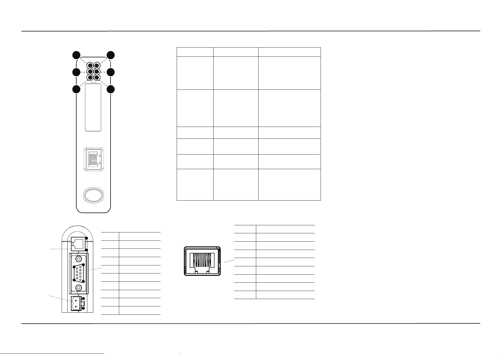
Module Front
LED Indicators
1
3
5
2
4
6
LED Indication Description
1 (Module Status) Off
2 (Network Status) Off
3 (Link) Off
4 (Activity) Off
5 (Subnet Status) Flashing green
6 (Device Status) Off
Green
Flashing Green
Flashing Red
Red
Flashing Green/Red
Green
Flashing Green
Red
Flashing Red
Flashing Green/Red
Green
Flashing Green
Green
Red
Alternating red/green
Green
Flashing green
Red
Flashing red
No power
Controlled by a scanner in run state
Not confi gured, or scanner in idle state
Minor fault (recoverable)
Major fault (unrecoverable)
Self-test in progress
No IP address, or no power
Online, one or more EtherNet/IP connections established
Online, no connections established
Duplicate IP address detected. Fatal error.
One or more connections timed out
Self-test in progress
No link
Connected to an Ethernet network
No Ethernet activity
Activity, receiving/transmitting Ethernet
packets
Running, but one or more transaction errors
Running
Transaction error/timeout or subnet stopped
Power off
Invalid or missing confi guration
Initializing
Running
Bootloader mode
Note the fl ash sequence pattern and contact
HMS support
Accessories Checklist
The following items are required for installation:
• Anybus Communicator Resource CD (Includes confi guration
software, manuals and application notes)
• RS232 confi guration cable
• Subnetwork connector
• Ethernet cable and connector (not included)
Installation and Startup Summary
• Mount the Communicator on the DIN-rail.
• Connect the Communicator to the Ethernet/IP network.
• Connect the Communicator to the subnetwork.
• Connect the confi guration cable between the Communicator
and the PC containing the Anybus Confi guration Manager
software (ACM).
• Power on the Communicator (+24 V DC).
• Confi gure the Communicator using ACM.
• Include the Anybus Communicator EDS fi le in the
Ethernet/IP confi guration tool.
• Confi gure and start the Ethernet/IP network.
Bottom View
PC Connector:
1. GND
2. GND
3. RS232 Rx
4. RS232 Tx
Power:
1. +24 V DC
2. GND
Ethernet/IP Connectors
Subnetwork Connector
Pin no. Description
1
1 +5V OUT
4
2 RS232 Rx
5
9
6
1
1
2
3 RS232 Tx
4NC
5 Signal GND
6 RS422 Rx+
7 RS422 Rx-
8 RS485+ / RS422 Tx+
9 RS485- / RS422 Tx-
18
Pin no Description
1 TD+
2 TD-
3 RD+
4 Termination
5 Termination
6 RD-
7 Termination
8 Termination
Further information and documents about this product can be
found at the product pages on www.anybus.com.
www.anybus.comSP0904, rev. 1.10, Mar 2015
Anybus Communicator Installation Sheet
UL Certifi cation
EMC Compliance (CE)Additional installation and operating
IND: CONT. EQ.
FOR HAZ LOC.
CL I, DIV 2
GP A,B,C,D
TEMP
CODE
E203225
Warnings!
• WARNING - EXPLOSION HAZARD - SUBSTITUTION OF
ANY COMPONENTS MAY IMPAIR SUITABILITY FOR
CLASS I, DIVISION 2.
• WARNING - EXPLOSION HAZARD - WHEN IN
HAZARDOUS LOCATIONS, TURN OFF POWER BEFORE
REPLACING OR WIRING MODULES.
• WARNING - EXPLOSION HAZARD - DO NOT
DISCONNECT EQUIPMENT UNLESS POWER HAS BEEN
SWITCHED OFF OR THE AREA IS KNOWN TO BE
NON-HAZARDOUS.
Attention!
• ATTENTION – RISQUE D’EXPLOSION – LE REMPLACEMENT DE TOUT COMPOSANTS INVALIDE LA
CERTIFICATION CLASS I, DIVISION 2.
• ATTENTION – RISQUE D’EXPLOSION – EN ZONE
EXPLOSIVE, VEUILLEZ COUPER L’ALIMENTATION
ÉLECTRIQUE AVANT LE REMPLACEMENT OU LE
RACCORDEMENT DES MODULES.
instructions
• Max Ambient Temperature: 55°C (for Hazloc environments)
• Field wiring terminal markings (wire type (Cu only, 14-30
AWG)).
• Use 60/75 or 75°C copper (Cu) wire only.
• Terminal tightening torque must be 5-7 lb-in (0.5 - 0.8 Nm).
• Use in overvoltage category 1 pollution degree 2 environment.
• Installed in an enclosure considered representative of the
intended use.
• Secondary circuit intended to be supplied from an isolating source and protected by overcurrent protective devices
installed in the fi eld sized per the following:
Control Circuit Wire Size Maximum Protective Device Rating
AWG (mm2) Amperes
22 (0.32) 3
20 (0.52) 5
18 (0.82) 7
16 (1.3) 10
14 (2.1) 20
12 (3.3) 25
ODVA Conformity
This product is in accordance with the EMC directive 89/336/EEC,
with amendments 92/31/EEC and 93/68/EEC through conformance
with the following standards:
• EN 50082-2 (1993)
EN 55011 (1990) Class A
• EN 61000-6-2 (1999)
EN 61000-4-3 (1996) 10 V/m
EN 61000-4-6 (1996) 10 V/m (all ports)
EN 61000-4-2 (1995) ±8 kV Air Discharge
±4 kV Contact discharge
EN 61000-4-4 (1995) ±2 kV Power port
±1 kV Other ports
EN 61000-4-5 (1995) ±0.5 kV Power ports (DM/CM)
±1 kV Signal ports
• ATTENTION – RISQUE D’EXPLOSION – NE PAS
DÉCONNECTER L’ÉQUIPEMENT TANT QUE
L’ALIMENTATION EST TOUJOURS PRÉSENTE OU
QUE LE PRODUIT EST TOUJOURS EN ZONE EXPLOSIVE ACTIVE.
EtherNet/IP CONFORMANCE TESTED™ is a certifi cation mark
of ODVA.
Further information and documents about this product can be
found at the product pages on www.anybus.com.
www.anybus.com
 Loading...