

Page 1
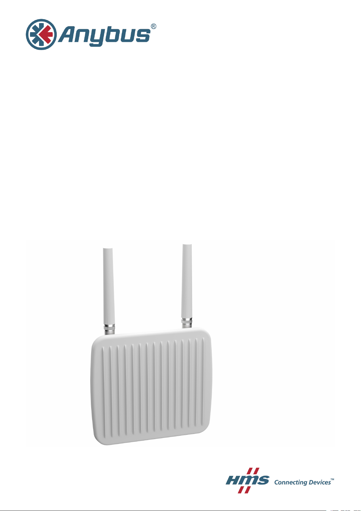
Anybus®WLAN Access Point IP67
USER MANUAL
SCM-1202-094-EN 1.0 ENGLISH
Page 2

Important User Information
Liability
Every care has been taken in the preparation of this document. Please inform HMS Industrial Networks AB of any
inaccuracies or omissions. The data and illustrations found in this document are not binding. We, HMS Industrial
Networks AB, reserve the right to modify our products in line with our policy of continuous product development.
The information in this document is subject to change without notice and should not be considered as a
commitment by HMS Industrial Networks AB. HMS Industrial Networks AB assumes no responsibility for any errors
that may appear in this document.
There are many applications of this product. Those responsible for the use of this device must ensure that all the
necessary steps have been taken to verify that the applications meet all performance and safety requirements
including any applicable laws, regulations, codes, and standards.
HMS Industrial Networks AB will under no circumstances assume liability or responsibility for any problems that
may arise as a result from the use of undocumented features, timing, or functional side effects found outside the
documented scope of this product. The effects caused by any direct or indirect use of such aspects of the product
are undefined, and may include e.g. compatibility issues and stability issues.
The examples and illustrations in this document are included solely for illustrative purposes. Because of the many
variables and requirements associated with any particular implementation, HMS Industrial Networks AB cannot
assume responsibility for actual use based on these examples and illustrations.
Intellectual Property Rights
HMS Industrial Networks AB has intellectual property rights relating to technology embodied in the product
described in this document. These intellectual property rights may include patents and pending patent applications
in the USA and other countries.
®
Anybus
are the property of their respective holders.
is a registered trademark of HMS Industrial Networks AB. All other trademarks mentioned in this document
Anybus®WLAN Access Point IP67 User Manual SCM-1202-094-EN 1.0
Page 3

Table of Contents
Page
1 Preface ............................................................................................................................... 3
1.1 About This Document .....................................................................................................3
1.2 Document history...........................................................................................................3
1.3 Document Conventions ..................................................................................................3
2 Description ....................................................................................................................... 4
3 Installation ........................................................................................................................ 5
3.1 Overview.......................................................................................................................5
3.2 Wall Mounting ................................................................................................................6
3.3 Pole Mounting ...............................................................................................................6
3.4 Connectors....................................................................................................................7
3.5 LED Indicators...............................................................................................................8
3.6 Factory Reset ................................................................................................................8
4 Configuration ................................................................................................................... 9
4.1 Overview..................................................................................................................... 10
4.2 Basic Settings.............................................................................................................. 11
4.3 Wireless Settings ......................................................................................................... 14
4.4 Advanced Settings.......................................................................................................18
4.5 Event Warning Settings ................................................................................................19
4.6 System Status ............................................................................................................. 22
4.7 Administrator ............................................................................................................... 24
A Wireless Technology Basics......................................................................................27
B Technical Data................................................................................................................ 28
B.1 Technical Specifications ............................................................................................... 28
B.2 Dimensions .................................................................................................................29
Anybus®WLAN Access Point IP67 User Manual SCM-1202-094-EN 1.0
Page 4

This page intentionally left blank
Page 5
Preface 3 (30)
1 Preface
1.1 About This Document
This document describes how to install and configure the Anybus WLAN Access Point IP67.
For additional documentation and software downloads, FAQs, troubleshooting guides and
technical support, please visit www.anybus.com/support.
1.2 Document history
Version Date Description
1.0 2018-04-10 First release
1.3 Document Conventions
Ordered lists are used for instructions that must be carried out in sequence:
1. First do this
2. Then do this
Unordered (bulleted) lists are used for:
• Itemized information
• Instructions that can be carried out in any order
...and for action-result type instructions:
► This action...
leads to this result
Bold typeface indicates interactive parts such as connectors and switches on the hardware, or
menus and buttons in a graphical user interface.
Monospaced text is used to indicate program code and other
kinds of data input/output such as configuration scripts.
This is a cross-reference within this document: Document Conventions, p. 3
This is an external link (URL): www.hms-networks.com
This is additional information which may facilitate installation and/or operation.
This instruction must be followed to avoid a risk of reduced functionality and/or
damage to the equipment, or to avoid a network security risk.
Caution
This instruction must be followed to avoid a risk of personal injury.
WARNING
This instruction must be followed to avoid a risk of death or serious injury.
Anybus®WLAN Access Point IP67 User Manual SCM-1202-094-EN 1.0
Page 6
Description 4 (30)
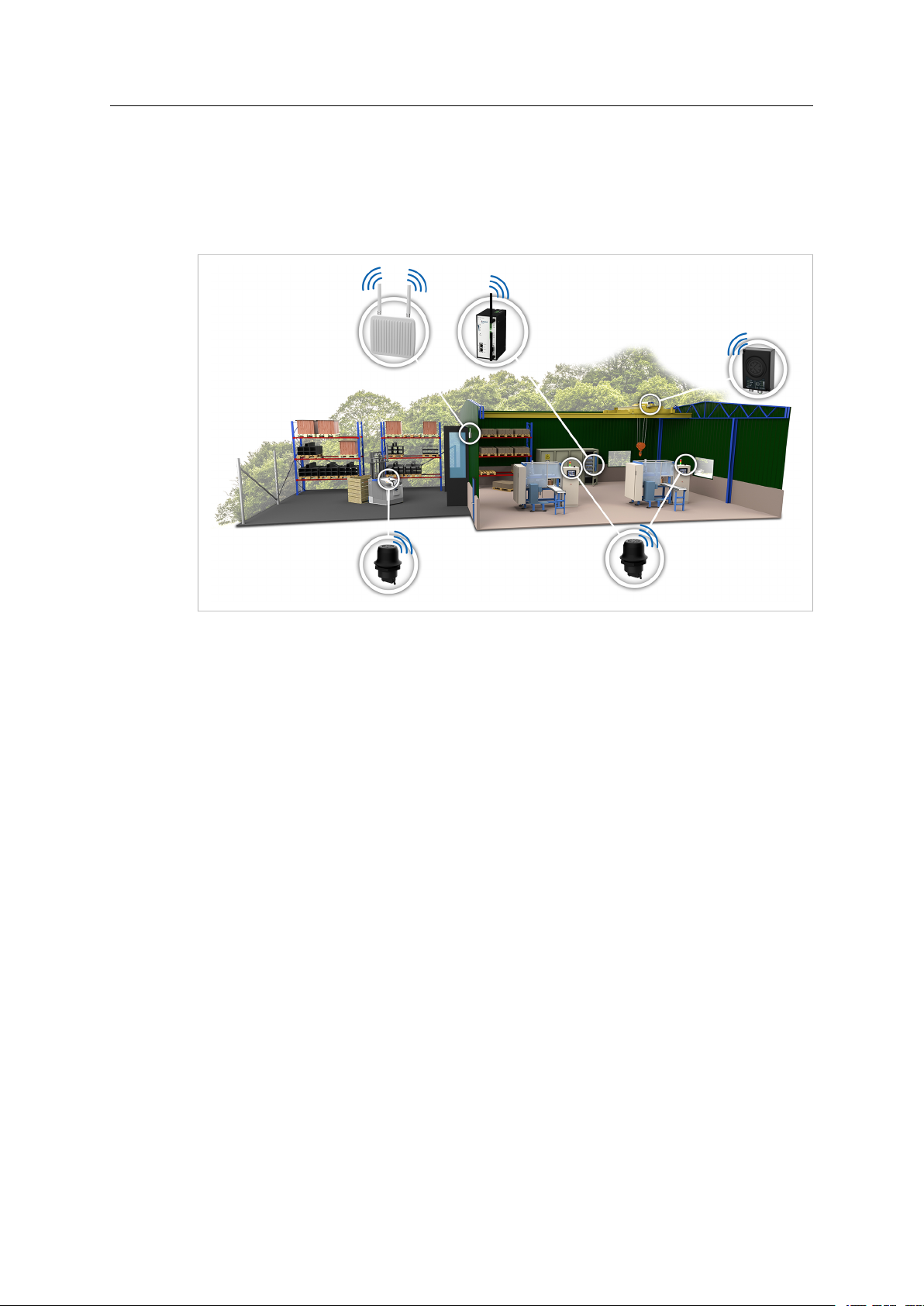
2 Description
Anybus WLAN Access Point IP67 is an industrial grade IEEE802.11 a/b/g/n dual-band wireless
infrastructure hub that can operate as a 2.4 GHz/5 GHz WLAN access point, client or wireless
bridge. It is designed to work seamlessly with other Anybus wireless devices to connect
machines to a wireless infrastructure.
Fig. 1 Wireless infrastructure example
Anybus WLAN Access Point IP67 supports Power over Ethernet (PoE) in compliance with the
IEEE 802.3af standard and has dual power supply inputs for redundancy.
The access point supports IEEE 802.1x to enhance security for WLAN connections. The
access point will act as authenticator and the clients will get authentication from a RADIUS
(Remote Authentication Dial In User Service) server.
Anybus®WLAN Access Point IP67 User Manual SCM-1202-094-EN 1.0
Page 7
Installation 5 (30)
3 Installation
Caution
This equipment emits RF energy in the ISM (Industrial, Scientific, Medical) band.
Make sure that all medical devices used in proximity to this device meet
appropriate susceptibility specifications for this type of RF energy.
This product contains parts that can be damaged by electrostatic discharge (ESD).
Use ESD prevention measures to avoid damage.
Make sure that you have all the necessary information about the capabilities and restrictions of
your local network environment before installation.
For optimal reception, wireless devices require a zone between them clear of objects that could
otherwise obstruct or reflect the signal. A minimum distance of 50 cm between the devices
should also be observed to avoid interference.
The unit can be screw-mounted onto a stable flat surface using the included wall mounting
plate, or pole-mounted using the included adjustable steel band straps.
To prevent water intrusion, the unit should be installed with the connectors on the
bottom panel facing down.
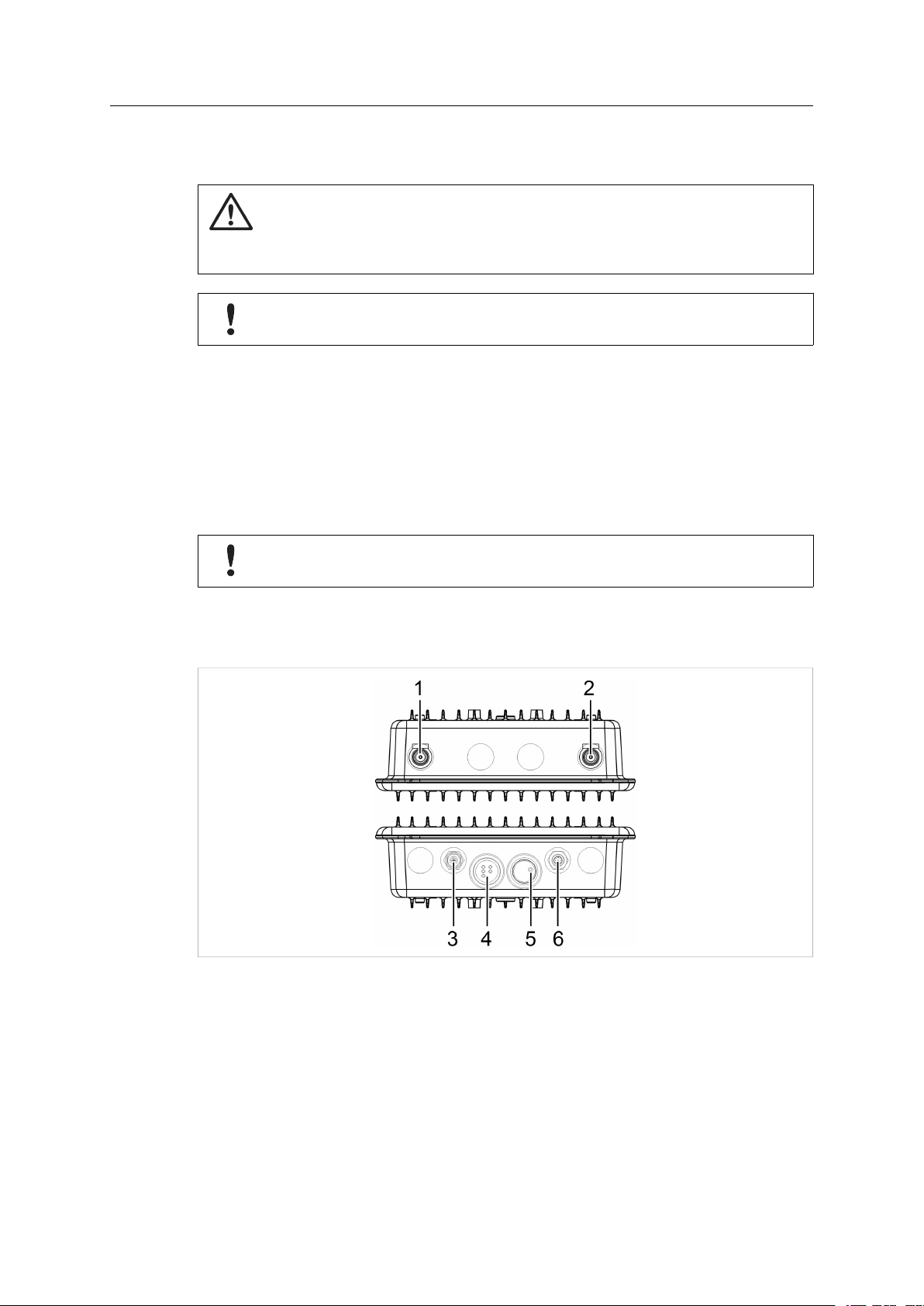
3.1 Overview
Fig. 2 Overview
Anybus
1, 2 Antenna connectors
3 Power connector (M12)
4 LED indicators
5 Reset button
6 Ethernet connector (M12)
®
WLAN Access Point IP67 User Manual SCM-1202-094-EN 1.0
Page 8
Installation 6 (30)
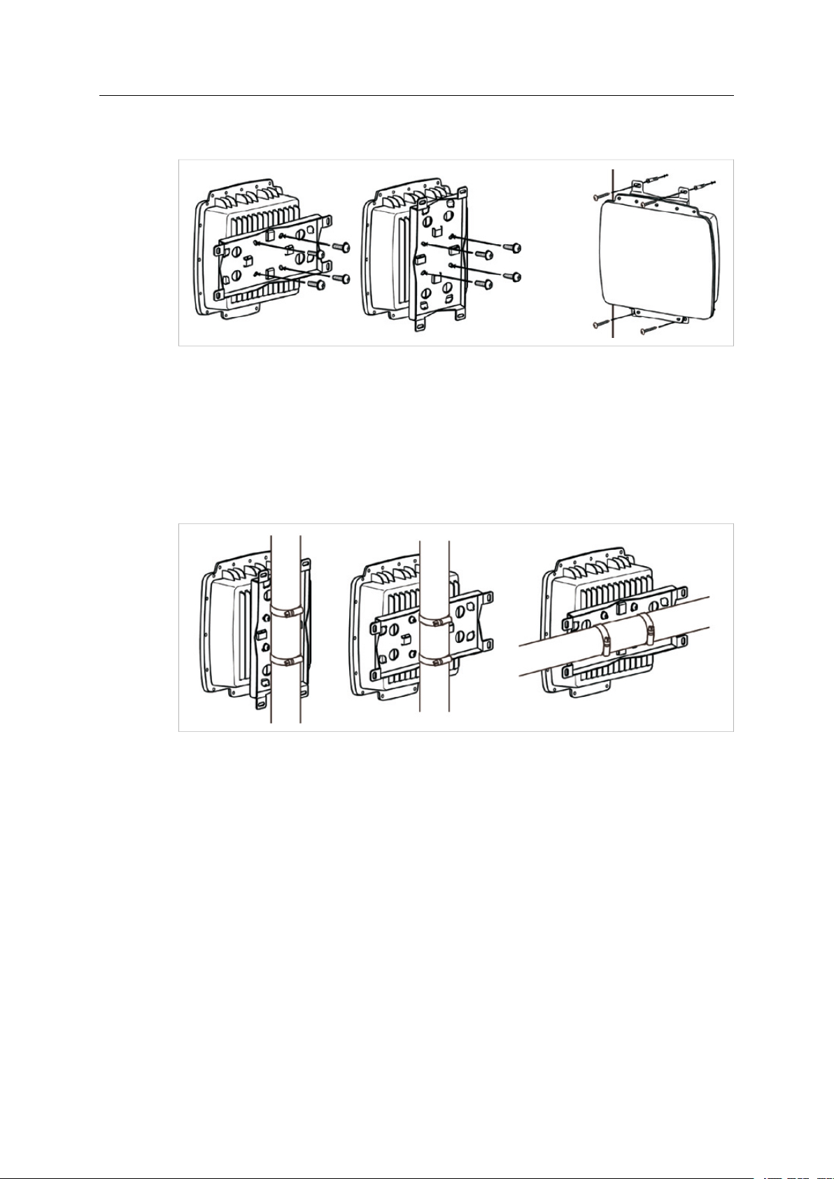
3.2 Wall Mounting
Fig. 3 Wall mounting
1. Attach the mounting plate to the back of the unit using the 4 included screws. The plate can
be attached vertically or horizontally.
2. Hold the unit upright against the wall and fasten it with 4 screws through the apertures in
the plate.
3.3 Pole Mounting
Fig. 4 Pole mounting
1. Attach the mounting plate to the back of the unit using the 4 included screws. The plate can
be attached vertically or horizontally.
2. Thread the two supplied metal mounting straps through the large slots on the mounting
plate and then put the straps around the pole.
Anybus®WLAN Access Point IP67 User Manual SCM-1202-094-EN 1.0
Page 9
Installation 7 (30)
3.4 Connectors
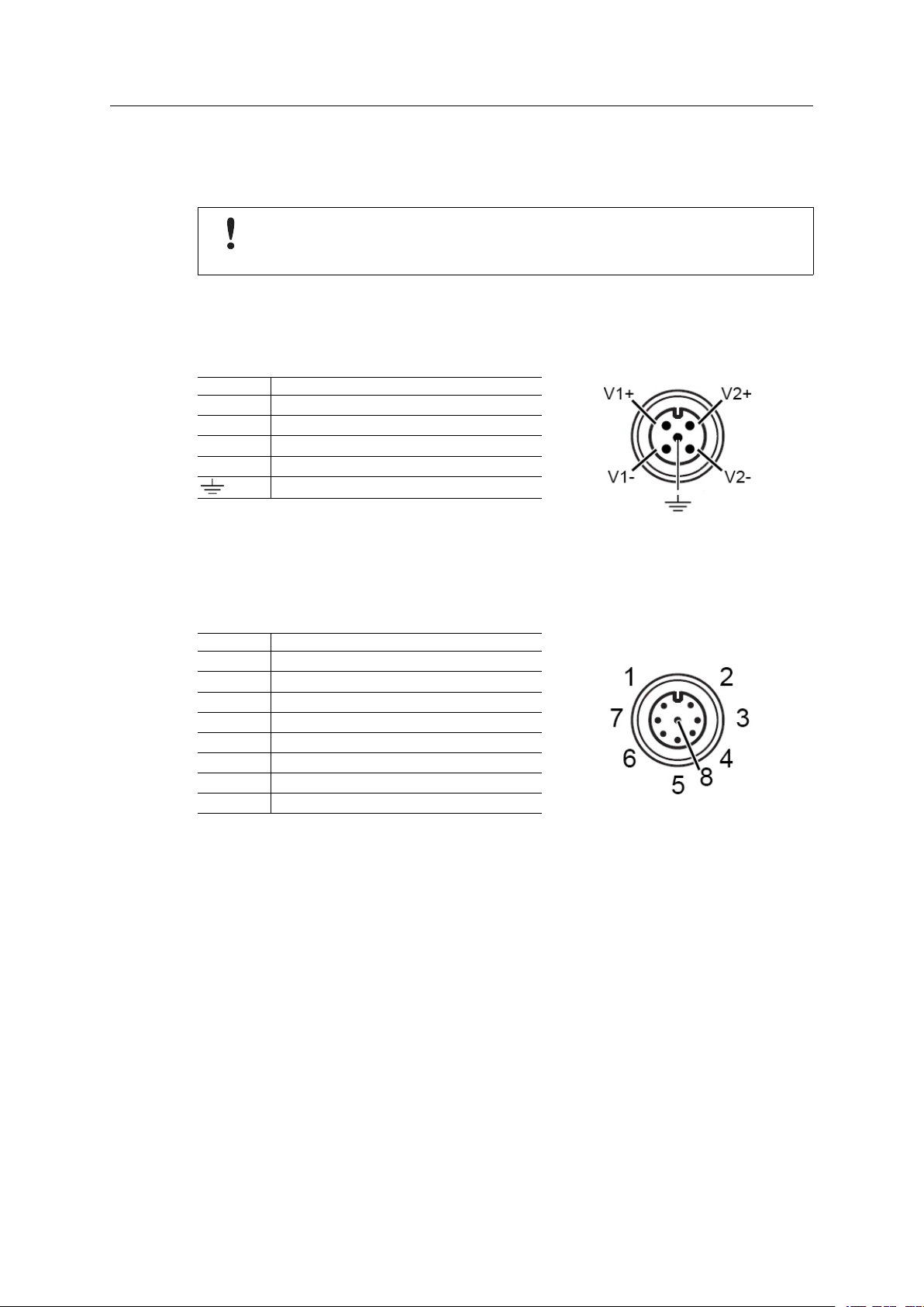
3.4.1 Power Connector (M12)
Connecting power with reverse polarity or using the wrong type of power supply
may damage the equipment. Make sure that the power supply is correctly
connected and of the recommended type.
The power connector is a 5-pin A-coded M12 type connector that supports dual power inputs
with a common ground connection.
See also Technical Data, p. 28 regarding power supply requirements.
Pin Function
V1+ Power Input 1 +
V1- Power Input 1 -
V2+ Power Input 2 +
V2- Power Input 2 -
Power Ground
3.4.2 Ethernet Connector (M12)
The Ethernet connector is an 8-pin A-coded M12 type connector. The Ethernet port supports
PoE (Power over Ethernet) compliant with IEEE 802.3af.
Pin Function
1 BI_DC+
2 BI_DD+
3 BI_DD-
4 BI_DA-
5 BI_DB+
6 BI_DA+
7
8 BI_DB-
BI_DC-
Anybus
®
WLAN Access Point IP67 User Manual SCM-1202-094-EN 1.0
Page 10
Installation 8 (30)
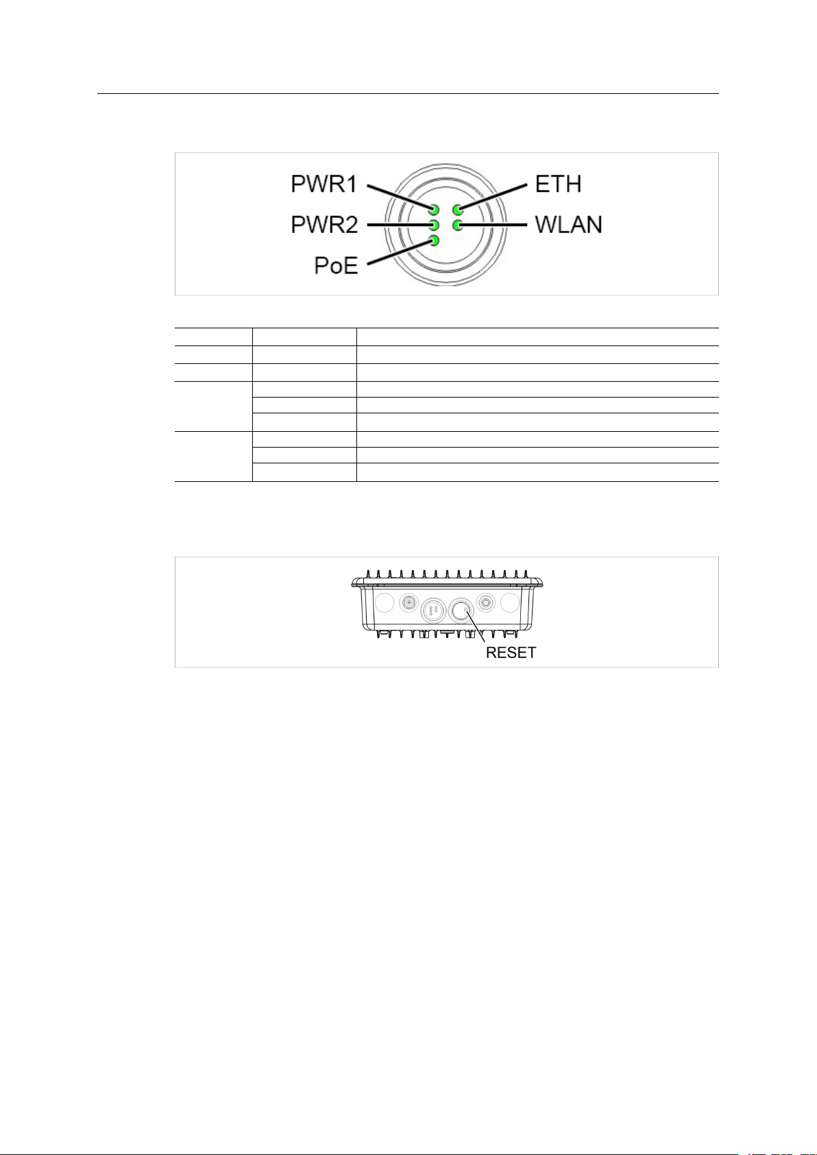
3.5 LED Indicators
Fig. 5 LED indicators on bottom panel
PWR1
PWR2 Green
PoE Green
ETH
WLAN
Green
Off No LAN
Green LAN link established
Green, flashing LAN traffic
Off No WLAN
Green WLAN link established
Green, flashing WLAN traffic
3.6 Factory Reset
Fig. 6 Reset
To restore the factory default settings, press and hold RESET on the front panel until the power
LED indicator(s) starts to flash, then release the button.
Power supplied on Power Input 1
Power supplied on Power Input 2
Power supplied on Ethernet port
Anybus®WLAN Access Point IP67 User Manual SCM-1202-094-EN 1.0
Page 11

Configuration 9 (30)
4 Configuration
Anybus WLAN Access Point IP67 is configured via the built-in web interface which is accessed
by pointing a standard web browser to the IP address of the access point. The default IP
address is 192.168.0.2. The computer accessing the web interface must be in the same IP
subnet as the access point.
The web interface is designed for the current stable versions of Internet Explorer,
Chrome, Firefox and Safari. Other browsers may or may not support the full
functionality of the web interface.
Fig. 7 Home page
Configuration Menu
Home Click on Run Wizard to perform a quick basic configuration of the Anybus WLAN
Access Point IP67.
For manual configuration or to modify the settings applied by the wizard, see the
descriptions of the configuration options in the following sections.
Overview Basic information about the access point and the Ethernet and wireless networks
Basic Settings Basic settings for the access point and the LAN interface
Wireless Settings Basic settings for the WLAN interface
Advanced Settings Advanced settings for the WLAN interface
Event Warning
Settings
System Status Detailed information about network connections and traffic
Administrator Password settings, configuration backup, unit reset, etc.
Logout Click to log out from the Anybus WLAN Access Point IP67.
Settings for alarm messaging and fault indication
Anybus
®
WLAN Access Point IP67 User Manual SCM-1202-094-EN 1.0
Page 12

Configuration 10 (30)
4.1 Overview
Basic information about the access point and the Ethernet and wireless networks. These pages
are read-only and have no editable settings.
4.1.1 System Info
Fig. 8 System Info
4.1.2 LAN Info
Fig. 9 LAN Info
4.1.3 Wireless Info
Anybus
Fig. 10 Wireless Info (AP and client modes)
®
WLAN Access Point IP67 User Manual SCM-1202-094-EN 1.0
Page 13

Configuration 11 (30)
4.2 Basic Settings
Basic settings for the access point and the Ethernet (LAN) interface
4.2.1 System Info Settings
Fig. 11 System Info Settings
Label Description
Device Name Define the name of the device
Device Location Enter the location of the device
Device Description Enter a description for the device
4.2.2 LAN Setting
Anybus
Fig. 12 LAN Setting
®
WLAN Access Point IP67 User Manual SCM-1202-094-EN 1.0
Page 14

Configuration 12 (30)
LAN Setting
Label Description
Obtain an IP address automatically IP settings will be assigned automatically by the DHCP server in
Use the following IP address Manually assign IP address, subnet mask, and default gateway.
Obtain DNS server address automatically Obtain a DNS server address from the DHCP server.
Use the following DNS server addresses Set a primary and secondary DNS server address.
Web Protocol Select HTTP (default) or HTTPS protocol for web access.
Port Specify a port to use for web access.
Web Access Control Enable web access over the wired or wireless connections.
DHCP Server When enabled, the device will act as DHCP server on your local
Start IP Address The starting IP address of the IP range assigned by the DHCP
Maximum Number of IPs Limits the number of IP addresses allowed to access the device.
Lease Time (Hour) The period of time that an IP address will be leased to a device.
your network.
The default port is 80 for HTTP and 443 for HTTPS.
network.
Do not enable this function if there is an active DHCP server
on the network.
server.
4.2.3 Time Setting
Anybus
Fig. 13 Time Setting
Time Setting
Label Description
NTP Enables or disables NTP function
NTP Server 1 The primary NTP server
NTP Server 2 The secondary NTP server
Time Zone Select the time zone you are located in
Synchronize Specify the scheduled time for synchronization
Local Date Set a local date manually
Local Time Set a local time manually
Get Current Date & Time from Browser Click to set the time from your browser
®
WLAN Access Point IP67 User Manual SCM-1202-094-EN 1.0
Page 15

Configuration 13 (30)
4.2.4 DIDO (Digital In/DigitalOut)
Fig. 14 DIDO Setting
The initial state of the digital outputs DO 1–4 can be set on this page. The default state is Off.
The digital inputs DI 1–4 are read-only.
Anybus®WLAN Access Point IP67 User Manual SCM-1202-094-EN 1.0
Page 16

Configuration 14 (30)
4.3 Wireless Settings
4.3.1 Wireless Settings
AP Access Point mode. The unit will act as a central connection point which other wireless
clients can connect to. This is the default mode.
AP-Client Provides one-to-many MAC address mapping so that multiple stations behind the AP
can transparently connect to the other AP even if they do not support WDS.
Client The unit will function as a wireless client to connect your wired devices to a wireless
network. This mode provides no access point services but supports 802.1X.
Bridge In this mode, the device functions as a bridge between the network on its WAN port and
the devices on its LAN port and those connected to it wirelessly.
Wireless settings – AP
Fig. 15 Wireless settings – AP
AP Settings
Label Description
Multiple SSID index The device supports multiple SSIDs (network names) which are indexed 1 to 4.
SSID Enter an SSID for the network.
Channel Select the WLAN channel to use for the access point. This channel will be used for
WDS-Master Mode When enabled, the unit will act as a WDS master on this network.
AP Isolation Prevents clients connected to the AP from communicating directly with each other.
Security options None: no encryption
This dropdown selects the index of the SSID to configure in the following settings.
all 4 SSIDs.
WEP: WEP (Wired Equivalent Privacy)
WPA/WPA2 Personal: uses a pre-shared key for authentication that is shared
between the AP and all clients.
802.1x: authentication through a RADIUS server.
WPA/WPA2 Enterprise: WPA/WPA2 Personal plus 802.1x RADIUS authentication.
See also RADIUS Authentication, p. 16.
Anybus
®
WLAN Access Point IP67 User Manual SCM-1202-094-EN 1.0
Page 17

Configuration 15 (30)
Wireless settings - Client
Fig. 16 Wireless settings – Client
Wireless Settings - Client
Label Description
Peer AP SSID Enter the SSID of the WLAN AP to connect to
Peer AP BSSID Enter the BSSID (MAC address) of the WLAN AP (if required)
Site Survey Click to scan for available wireless networks
WDS-Slave Mode When enabled, the unit will act as a WDS slave on this network.
Security options See Wireless settings – AP, p. 14
Wireless settings - Bridge
Fig. 17 Wireless settings – Bridge
Wireless settings - Bridge
Label Description
WDS Mode WDS can be set to operate in Bridge Mode or Repeater Mode. See below for an
Peer MAC Address Enter the MAC address of each access point and check the Enable box.
SSID (Repeater Mode) Enter an SSID (network name) for the network. All devices must be configured with
Channel Enter the WLAN channel to use for the network. All devices must be configured to
Security options See Wireless settings – AP, p. 14
explanation of these modes.
the same SSID.
use this channel.
Anybus
®
WLAN Access Point IP67 User Manual SCM-1202-094-EN 1.0
Page 18

Configuration 16 (30)
WDS Bridge Mode
In this mode the AP acts as a standard bridge that forwards traffic between WDS links
(connected APs or wireless bridges) and an Ethernet port. As a standard bridge, the AP learns
MAC addresses of up to 64 wireless or 128 wired and wireless network devices, which are
connected to their respective Ethernet ports to limit the amount of forwarded data. Only data
destined for stations which are known to reside on the peer Ethernet link, multicast data or data
with unknown destinations need to be forwarded to the peer AP via the WDS link. The peer
WDS APs are based on the MAC addresses listed in Peer MAC Address.
When using WDS Bridge Mode:
• LAN IP address should use a different IP in the same network.
• Shut down all DHCP server functions of the AP
• Enable WDS.
• Each AP should have the same setting except Peer MAC Address which should be set to
the MAC address of the other unit.
• The settings of security and channel must be the same.
• The distance of the AP should be limited within a certainty area.
WDS Repeater Mode
This mode extends the range of the wireless infrastructure by forwarding traffic between
associated wireless stations and another repeater or AP connected to the wired LAN. The peer
WDS APs are based on the MAC addresses listed in Peer MAC Address 1–4.
RADIUS Authentication
Fig. 18 Network with RADIUS authentication
RADIUS (Remote Authentication Dial-In User Service) is a widely deployed protocol that
enables companies to authenticate and authorize remote users’ access to a system or service
from a central network server.
When you configure the remote access server for RADIUS authentication, the credentials of the
connection request are passed to the RADIUS server for authentication and authorization. After
the request is both authenticated and authorized, the RADIUS server sends an accept
message back to the remote access server and the connection attempt is accepted. Otherwise,
the RADIUS server sends a reject message back to the remote access server and the
connection attempt is rejected.
Anybus®WLAN Access Point IP67 User Manual SCM-1202-094-EN 1.0
Page 19

Configuration 17 (30)
4.3.2 Wireless Options
Fig. 19 Wireless options
Wireless options
Label Description
Radio Enable/disable the WLAN interface.
Wireless Mode Select 2.4 GHz or 5 GHz operation.
SSID Broadcast Select if the SSID of the unit should be broadcasted or not.
Beacon Interval
DTIM Interval
Fragmentation Threshold
RTS Threshold
Preamble
Tx Multicast Rate
HT Require
HT Band Width
HT Guard Interval
HT Extension Channel
HT Tx STBC
HT Rx STBC
HT LDPC
These settings are for advanced configuration only and should normally be
left at their default values.
Anybus
®
WLAN Access Point IP67 User Manual SCM-1202-094-EN 1.0
Page 20

Configuration 18 (30)
4.4 Advanced Settings
4.4.1 Filters
Fig. 20 Filters
Allows you to set up MAC filters to allow or deny wireless clients to connect to the access point.
You can add a MAC address manually or select one of the currently associated clients.
Filters
Label Description
MAC Filter Enable/disable MAC filtering
Options Select to allow or deny access for the listed MAC addresses
Associated Clients Select the MAC address of a client, then use the Copy To dropdown to add it to the
MAC Filter Table Enter MAC addresses to be filtered
4.4.2 Misc. Settings
Fig. 21 Additional settings
Misc. Settings
Label Description
UPnP Enables or disables UPnP
LLDP Protocol Enables or disables the LLDP protocol
desired slot in the filter table.
Anybus
®
WLAN Access Point IP67 User Manual SCM-1202-094-EN 1.0
Page 21

Configuration 19 (30)
4.5 Event Warning Settings
The unit can be configured to issue notifications in various ways for selected events. Fill in the
required settings on the following pages and check the corresponding box for each event to
enable reporting.
4.5.1 System Log
Anybus
Fig. 22 System log settings
Syslog Server Settings
Label Description
Syslog Server IP Enter the IP address of a syslog server if you want the logs to be stored remotely.
Syslog Server Port Specifies the syslog port. The default port is 514.
®
WLAN Access Point IP67 User Manual SCM-1202-094-EN 1.0
Leave this field blank to disable remote syslog.
Page 22

Configuration 20 (30)
4.5.2 E-mail
Fig. 23 E-mail
E-mail Server Settings
Label Description
SMTP Server/Port Enter the SMTP server address and port.
E-mail Address 1–4 Enter up to 4 email addresses that will receive the notifications.
Click the checkbox and enter authentication information if required by the SMTP server.
4.5.3 SNMP
Fig. 24 SNMP settings
SNMP Settings
Label Description
SNMP Agent Enable/disable SNMP reporting
SNMP Trap Server 1-4 Enter the IP address of the SNMP server(s)
Community
SysContact
As requiredSysLocation
Anybus
®
WLAN Access Point IP67 User Manual SCM-1202-094-EN 1.0
Page 23

Configuration 21 (30)
4.5.4 Relay
Fig. 25 Fault LED/Relay settings
Select events that should trigger the Fault LED and relay output.
Anybus®WLAN Access Point IP67 User Manual SCM-1202-094-EN 1.0
Page 24

Configuration 22 (30)
4.6 System Status
4.6.1 Wireless Link List
Fig. 26 Wireless link list
Lists the wireless clients that are currently connected to the access point.
Click on Refresh to update the list.
4.6.2 DHCP Client List
Fig. 27 DHCP client list
Lists the devices on your network that are receiving dynamic IP addresses from the built-in
DHCP server.
Anybus®WLAN Access Point IP67 User Manual SCM-1202-094-EN 1.0
Page 25

Configuration 23 (30)
4.6.3 Traffic/Port Status
Fig. 28 Traffic/port status
Network traffic statistics for both received and transmitted packets through the Ethernet and
wireless connections. The traffic counter will reset when the device is rebooted.
Click on Refresh to update the list.
4.6.4 System Log
Fig. 29 System log
Events and activities are logged continuously in the system log.
Click Refresh to renew the page or Clear to clear the log entries.
Anybus®WLAN Access Point IP67 User Manual SCM-1202-094-EN 1.0
Page 26

Configuration 24 (30)
4.7 Administrator
4.7.1 Password
Fig. 30 Password
This page allows you to change the user ID and password for web access. The default user ID
and password are both admin.
For security reasons the default password should always be changed.
Password
Label Description
Old Name Enter the current user ID
Old Password Enter the current password
New Name Enter a new user ID. The user ID must consist of 1 to 15 characters and can only
New Password Enter the new password. The password must consist of 1 to 15 characters and can
Confirm New Password Enter the new password again.
include A-Z, a-z, 0–9.
only include A-Z, a-z, 0–9.
Anybus
®
WLAN Access Point IP67 User Manual SCM-1202-094-EN 1.0
Page 27

Configuration 25 (30)
4.7.2 Configuration
Fig. 31 Configuration
This page allows you to save and restore configurations.
Configuration
Label Description
Download Click to save the current configuration as a file on your computer.
Choose File/Upload Click on Choose File to locate a saved configuration file, then click on Upload to
install it. The unit will automatically validate the configuration file and then restart
the unit with the uploaded configuration.
4.7.3 Firmware Upgrade
Fig. 32 Firmware upgrade
1. Download the firmware file from www.anybus.com/support and save it to your computer.
Make sure that the file is the correct one for your access point model and version.
2. Click on Choose File and select the downloaded firmware file.
3. Click on Start Upgrade to apply the new firmware.
The unit will reboot automatically when the upgrade is completed.
Do not power off the unit while the upgrade is in progress as this may put the unit
in an unrecoverable state.
Anybus®WLAN Access Point IP67 User Manual SCM-1202-094-EN 1.0
Page 28

Configuration 26 (30)
4.7.4 Load Factory Default
Fig. 33 Load factory default
Click on Restore Default Settings to restore the unit to the factory default settings.
4.7.5 Restart
Fig. 34 Restart
Click on Restart Now to restart the unit.
Anybus®WLAN Access Point IP67 User Manual SCM-1202-094-EN 1.0
Page 29

Appendix A: Wireless Technology Basics 27 (30)
A Wireless Technology Basics
Wireless technology is based on the propagation and reception of electromagnetic waves.
These waves respond in different ways in terms of propagation, dispersion, diffraction and
reflection depending on their frequency and the medium in which they are travelling.
To enable communication there should optimally be an unobstructed line of sight between the
antennas of the devices. However, the so called Fresnel Zones should also be kept clear from
obstacles, as radio waves reflected from objects within these zones may reach the receiver out
of phase, reducing the strength of the original signal (also known as phase cancelling).
Fresnel zones can be thought of as ellipsoid three-dimensional shapes between two wireless
devices. The size and shape of the zones depend on the distance between the devices and on
the signal wave length. As a rule of thumb, at least 60 % of the first (innermost) Fresnel zone
must be free of obstacles to maintain good reception.
Fig. 35 Fresnel zones
Area to keep clear of obstacles (first Fresnel zone)
Distance (d)
100 m 1.7 m 1.2 m
200 m 2.5 m 1.7 m
300 m 3.0 m 2.1 m
400 m 3.5 m 2.4 m
2.4 GHz (WLAN or Bluetooth) 5 GHz (WLAN)
Fresnel zone radius (r)
The wireless signal may be adequate even if there are obstacles within the Fresnel zones, as it
always depends on the number and size of the obstacles and where they are located. This is
especially true indoors, where reflections on metal objects may actually help the propagation of
radio waves. To reduce interference and phase cancelling, the transmission power of the unit
may in some cases have to be reduced to limit the range.
It is therefore recommended to use a wireless signal analysis tool for determining the optimal
placement and configuration of a wireless device.
Anybus®WLAN Access Point IP67 User Manual SCM-1202-094-EN 1.0
Page 30

Appendix B: Technical Data 28 (30)
B Technical Data
B.1 Technical Specifications
Order code EU: AWB4003
Wireless antenna External (N-type)
Maximum range 400 meters
Wired interface Ethernet
Ethernet port 10/100/1000Base-T(X) Auto MDI/MDX
Power connector M12 5-pin female A-coded connector
Power supply 2 x 12–48 VDC
Power consumption 9 W
Dimensions (WxHxD) 310 x 87 x 310 mm
Weight 2.56 kg
Operating temperature -25 to +70 °C
Storage temperature -40 to +85 °C
Humidity 5 % to 95 % non-condensing
Mounting Wall mount or pole mount
Housing Metal
Protection class IP67
Certifications See datasheet
US: AWB4004
M12 8-pin female A-coded connector
(dual power inputs in single connector)
Power over Ethernet IEEE 802.3af
For more technical details and specifications, visit www.anybus.com/support.
Anybus®WLAN Access Point IP67 User Manual SCM-1202-094-EN 1.0
Page 31

Appendix B: Technical Data 29 (30)
B.2 Dimensions
Fig. 36 Installation drawing
All measurements are in mm.
Anybus®WLAN Access Point IP67 User Manual SCM-1202-094-EN 1.0
Page 32

last page
© 2018 HMS Industrial Networks AB
Box 4126
300 04 Halmstad, Sweden
info@hms.se SCM-1202-094-EN 1.0.8151 / 2018-04-11
 Loading...