

Page 1
Anybus®Wireless Bolt
STARTUP GUIDE
SCM-1202-006/SP2139 2.2 ENGLISH
™
Page 2

Important User Information
Liability
Every care has been taken in the preparation of this document. Please inform HMS Industrial Networks AB of any inaccuracies or omissions. The data and illustrations found in this document are
not binding. We, HMS Industrial Networks AB, reserve the right to modify our products in line with
our policy of continuous product development. The information in this document is subject to
change without notice and should not be considered as a commitment by HMS Industrial Networks
AB. HMS Industrial Networks AB assumes no responsibility for any errors that may appear in this
document.
There are many applications of this product. Those responsible for the use of this device must ensure that all the necessary steps have been taken to verify that the applications meet all performance and safety requirements including any applicable laws, regulations, codes, and standards.
HMS Industrial Networks AB will under no circumstances assume liability or responsibility for any
problems that may arise as a result from the use of undocumented features, timing, or functional
side effects found outside the documented scope of this product. The effects caused by any direct
or indirect use of such aspects of the product are undefined, and may include e.g. compatibility issues and stability issues.
The examples and illustrations in this document are included solely for illustrative purposes. Because of the many variables and requirements associated with any particular implementation,
HMS Industrial Networks AB cannot assume responsibility for actual use based on these examples and illustrations.
Intellectual Property Rights
HMS Industrial Networks AB has intellectual property rights relating to technology embodied in the
product described in this document. These intellectual property rights may include patents and
pending patent applications in the USA and other countries.
Anybus®Wireless Bolt™Startup Guide SCM-1202-006/SP2139 2.2
Page 3

About This Document 3 (16)
1 About This Document
This document describes how to install Anybus Wireless Bolt and set up a basic
configuration. For additional documentation and technical support, please visit
the Anybus support website www.anybus.com/support.
Trademark Information
®
Anybus
is a registered trademark and Wireless Bolt™is a trademark of HMS Industrial Networks AB. All other trademarks mentioned in this document are the
property of their respective holders.
2 Product Description
Anybus Wireless Bolt provides wireless communication over WLAN and/or
®
Bluetooth
Typical applications for Anybus Wireless Bolt include:
• Adding wireless cloud connectivity to industrial devices
• Accessing devices from a laptop, smartphone or tablet
• Ethernet cable replacement between devices
Limitations:
Bluetooth PAN (Personal Area Network) may not work with some devices due to
different implementations of Bluetooth by different manufacturers.
WLAN 5 GHz cannot be used at the same time as WLAN 2.4 GHz or Bluetooth.
WLAN or Bluetooth?
Choose WLAN when data throughput and seamless roaming are most important
and there are few other radio emitting devices in the environment.
Choose Bluetooth if connection robustness and low latency are most important,
and in environments with many other radio emitters.
to wired networks.
Anybus®Wireless Bolt™Startup Guide SCM-1202-006/SP2139 2.2
Page 4

Installation 4 (16)
3 Installation
Caution
This equipment emits RF energy in the ISM (Industrial, Scientific,
Medical) band. Make sure that all medical devices used in proximity to
this device meet appropriate susceptibility specifications for this type of
RF energy.
This product contains parts that can be damaged by electrostatic
discharge (ESD). Use ESD protective measures to avoid equipment
damage.
Make sure that you have all the necessary information about the capabilities and
restrictions of your local network environment before installation.
For optimal reception, wireless devices require a zone between them clear of objects that could otherwise obstruct or reflect the signal. A minimum distance of
50 cm between the devices should also be observed to avoid interference.
The characteristics of the antenna should also be considered when choosing the
placement and orientation of the unit.
See the Anybus Wireless Bolt User Manual for more information.
Anybus®Wireless Bolt™Startup Guide SCM-1202-006/SP2139 2.2
Page 5
Installation 5 (16)
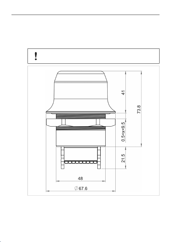
Mechanical Installation
Anybus Wireless Bolt is intended to be mounted on top of a machine or cabinet
through an M50 (50.5 mm) hole using the included sealing ring and nut.
Tightening torque: 5 Nm ±10 %
Make sure that the sealing ring is correctly placed in the circular groove
in the top part of the housing before tightening the nut.
All measurements are in mm.
Anybus®Wireless Bolt™Startup Guide SCM-1202-006/SP2139 2.2
Page 6

Installation 6 (16)
Connector Pinning
Note the location of the RESET button when the connector is attached to the
Wireless Bolt. Pin 1 will be the pin closest to the button.
Pin Name
1 VIN Power 9–30 VDC
2 GND Power Ground
3 DI
DI_GND Digital input ground
4
ETN_RD+ Ethernet receive + (white/orange)
5
ETN_RD- Ethernet receive - (orange)
6
ETN_TD- Ethernet transmit - (green)
7
ETN_TD+ Ethernet transmit + (white/green)
8
RS485_B
9
10 FE/Shield
RS232_TXD
11
RS485_A/RS232_RXD
12
RS232_RTS RS-232 Request To Send
13
RS232_CTS
14
ISO_5V
15
ISO_GND
16
CAN_L
17
CAN_H CAN High
18
Description
Digital input (9–30 VDC)
RS-485 B Line
Ethernet:
Serial:
RS-232 Transmit
RS-485 A Line / RS-232 Receive
RS-232 Clear To Send
Isolated 5 V for serial interface
Isolated Ground for serial interface
CAN Low
Functional Earth
Functional Earth and Shield
• If using a shielded Ethernet cable the shield must be unconnected.
• RS-232 and RS-485 cannot be used at the same time.
• Use termination for RS-485 and CAN when required.
Anybus®Wireless Bolt™Startup Guide SCM-1202-006/SP2139 2.2
Page 7

Installation 7 (16)
Cabling
To make an Ethernet connector cable for the Anybus Wireless Bolt:
1. Cut off one of the connectors on a standard Cat5e or Cat6 Ethernet cable.
2. Strip off about 40 mm (1½ inch) of the cable jacket and untwist the orange,
orange/white, green and green/white wires. The other wires will not be used.
3. Strip off about 7 mm (¼ inch) of the isolation on each wire.
4. Push the pin spring release next to each socket on the connector and insert
the correct wire end according to Connector Pinning, p. 6.
Connect the wires from the power supply to the connector in the same way as
the Ethernet wiring. Make sure that polarity is not reversed.
Anybus®Wireless Bolt™Startup Guide SCM-1202-006/SP2139 2.2
Page 8

Configuration 8 (16)
4 Configuration
Anybus Wireless Bolt can be configured via the web interface or using one of the
pre-configured Easy Config modes.
Advanced configuration can be carried out by issuing AT (modem) commands
through the web interface or over a Telnet or RAW TCP connection to port 8080.
A list the of supported ATcommands is included in the web interface.
4.1 Web Interface
The web interface is accessed by pointing your web browser to the IP address of
the Wireless Bolt. The default address is 192.168.0.99.
Most configuration settings are self-explanatory. See also the built-in help and
the Anybus Wireless Bolt User Manual.
The web interface is designed for the current stable versions of Internet
Explorer, Chrome, Firefox and Safari. Other browser versions may not
support all functions of the interface.
Anybus®Wireless Bolt™Startup Guide SCM-1202-006/SP2139 2.2
Page 9

Configuration 9 (16)
4.2 Easy Config Modes
The following Easy Config Modes can be set from the web interface.
Mode Role Description
2 — Reset the configuration to the factory defaults
3 — Reset the IP settings to the factory defaults
4 Client Wait for discovery and configuration
5 WLAN AP
6 Bluetooth NAP
Usage
Modes 4, 5 and 6 are used in combination to automatically set up a WLAN or
Bluetooth network of Wireless Bolt or Wireless Bridge II units.
Modes 5 and 6 will scan for units in Mode 4. Each detected unit in Mode 4 will be
reconfigured as a client, and the scanning unit will be configured as an access
point. The clients will then restart and connect to the access point.
Mode Timeout
• Mode 5 and 6 will scan for 120 seconds. To scan for additional units, just ac-
tivate the mode again.
• Mode 4 will listen for 120 seconds or until it has received a valid configura-
tion from a unit in Mode 5 or 6.
The IP address of a client may be changed by the configuration from the
access point. Active browser sessions could therefore be lost.
Discover units in Mode 4 and configure them as WLAN or
Bluetooth PANU clients
Anybus®Wireless Bolt™Startup Guide SCM-1202-006/SP2139 2.2
Page 10

Configuration 10 (16)
4.3 Factory Restore
The unit can be restored to the factory default settings using any of the following
methods:
► Press and hold the RESET button for >10 seconds and then release it
► Execute Easy Config Mode 2
► Click on Factory Restore on the System Settings page
► Issue the ATcommand AT&F and reboot
Default Network Settings
IP Assignment Static
IP Address 192.168.0.99
Subnet Mask 255.255.255.0
Default Gateway 192.168.0.99
Default WLAN Settings
Operating Mode Client
Channel Bands 2.4 GHz & 5 GHz
Authentication Mode Open
Channel Auto
Bridge Mode Layer 2 tunnel
Default Bluetooth Settings
Operating Mode PANU (Client)
Local Name [generated from MAC address]
Security Mode Disabled
Default System Settings
Password [empty]
Setting a secure password for the unit is strongly recommended.
Anybus®Wireless Bolt™Startup Guide SCM-1202-006/SP2139 2.2
Page 11

Configuration 11 (16)
4.4 RESET
The RESET button is located on the bottom of the unit next to the connector.
► Press and hold the button for >10 seconds and then release it to reset to the
factory default settings (when the unit is powered on).
► Press and hold the button during startup to enter Recovery Mode.
Recovery Mode
If the web interface cannot be accessed, the unit may be reset by starting in
Recovery Mode and reinstalling the firmware using Anybus Firmware Manager II.
For instructions, please refer to the wizard in Anybus Firmware Manager II.
Firmware updates should normally be carried out through the web
interface. Recovery Mode should only be used if the unit is unresponsive
and the web interface cannot be accessed.
Anybus®Wireless Bolt™Startup Guide SCM-1202-006/SP2139 2.2
Page 12
Configuration 12 (16)
4.5 Configuration Examples
Settings not mentioned here should be left at their default values.
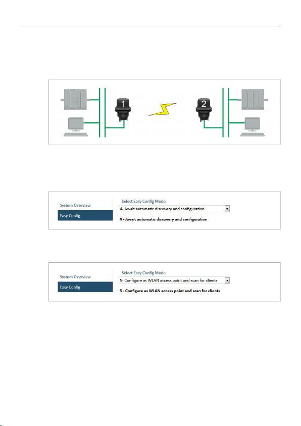
EXAMPLE 1: Setting up a network bridge with Easy Config
This example describes how to connect two Ethernet network segments over
WLAN or Bluetooth using two Wireless Bolts.
1. On Wireless Bolt 1, execute Easy Config Mode 4. This unit will now be dis-
coverable and open for automatic configuration.
2. On Wireless Bolt 2, execute Easy Config Mode 5 for WLAN or 6 for Blue-
tooth. This unit will now automatically discover and configure the other unit
as a WLAN or Bluetooth PANU client.
The Easy Config modes will time out after 120 seconds.
PROFINET communication
WLAN communication with PROFINET devices requires that Bridge Mode is set
to Layer 2 tunnel on the WLAN Settings page of the web interface.
Anybus®Wireless Bolt™Startup Guide SCM-1202-006/SP2139 2.2
Page 13
Configuration 13 (16)
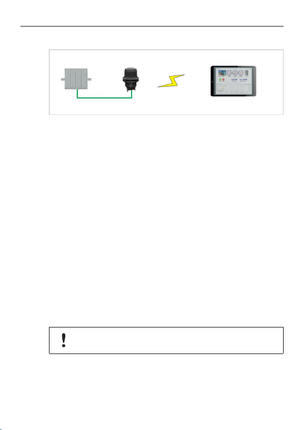
EXAMPLE 2: Accessing a PLC from a handheld device over WLAN
This example describes how to access the web interface of a PLC from a handheld device such as a tablet or smartphone using WLAN.
A: PLC or network has an active DHCP server
1. In Network Settings, select IP Assignment: Dynamic (DHCP), then skip
to step 3 below.
B: PLC has a static IP address, no DHCP server on the network
1. Make sure that the IP addresses of the PLC and the Wireless Bolt are within
the same Ethernet subnet.
2. In Network Settings, select IP Assignment: Static and Internal DHCP
Server: DHCP Server Enabled.
3. In WLAN Settings, select Operating Mode: Access Point.
Change the SSID, authentication mode and WLAN channel only if required
by your network environment, otherwise leave them at the default settings.
4. Click on Save and Reboot to restart the unit with the new settings.
5. In the WLAN configuration of the handheld device, connect to the SSID of
the Wireless Bolt.
You should now be able access the web interface of the PLC by entering its
IP address in the web browser on the handheld device.
Do not enable the internal DHCP server if there is already an active
DHCP server on the local network.
Anybus®Wireless Bolt™Startup Guide SCM-1202-006/SP2139 2.2
Page 14

Technical Data 14 (16)
5 Technical Data
5.1 Technical Specifications
Order code AWB2000 AWB2010 AWB2020
Wired Interface type Ethernet Serial RS-232/485 +
Wireless antenna Internal
Maximum range 100 m (WLAN and Bluetooth)
Communication See Anybus Wireless Bolt Datasheet
Dimensions Height: 70 mm (95 mm incl. connector, 41 mm outside)
Weight 81 g
Operating temperature -40 to +65 °C
Storage temperature -40 to +85 °C
Humidity EN 600068-2-78: Damp heat, +40 °C, 93 % humidity for 4 days
Housing Plastic
Protection class IP67 for top part (outside of host)
Mounting M50 screw and nut (50.5 mm hole required)
Connector Included plug connector
Power supply 9–30 VDC (-5 % +20 %)
Power consumption 0.7 W (idle) – 1.7 W (max)
Certifications See Anybus Wireless Bolt Compliance Sheet
Diameter: 70 mm
IP21 for bottom part (inside of host)
Cranking 12 V (ISO 7637-2:2011 pulse 4)
Reverse polarity protection
Ethernet
CAN + Ethernet
Anybus®Wireless Bolt™Startup Guide SCM-1202-006/SP2139 2.2
Page 15

Technical Data 15 (16)
5.2 Internal Antenna Characteristics
The following radiation diagrams show the characteristics of the internal antenna
under laboratory test conditions. The diagrams are intended to be used as a general guide for finding the optimal placement and orientation of the unit.
2.4 GHz antenna gain and directivity in horizontal and vertical planes
Anybus®Wireless Bolt™Startup Guide SCM-1202-006/SP2139 2.2
Page 16

last page
© 2017 HMS Industrial Networks AB
Box 4126
300 04 Halmstad, Sweden
info@hms.se
SCM-1202-006/SP2139 2.2..4482 / 2017-06-15T07:31:47
 Loading...