

Page 1

MMIIRRAACCLLEE SSTTEEAAMMEERR
Models MS-150/155,
MS-250/255 & MS-355
Owner’s Manual
P/N 1010699 Rev. B
MANUFACTURING
NUMBERS:
9100420
9100426
9100428
9100430
9100436
9100438
9100450
9100456
9100458
9100460
9100462
9100466
9100468
9100480
9100486
®
C
US
Page 2

MIRACLE STEAMER
1
P/N 1010699 Rev. B
A.J. Antunes & Co.
General
The Miracle Steamer produces steam using plain tap
water for quick heating and reconstituting of food items.
Simple pushbutton action delivers a fully adjustable
impulse of steam. Because the amount of steam is
consistent, it removes the guesswork and produces a
uniform finished product from one operator to the next.
This manual provides the safety, installation and operating procedures for the Miracle Steamer. We recommend that all information contained in this manual be
read prior to installing and operating the unit.
Your Miracle Steamer is manufactured from the finest
materials available and is assembled to Roundup’s
strict quality standards. This unit has been tested at
the factory to ensure dependable trouble-free operation.
Warranty Information
Please read the full text of the Limited Warranty in this
manual.
OWNER INFORMATION
Operation ...................................................................8
General ......................................................................
8
Operating Instructions ...............................................
9
Programming .............................................................
9
Steaming Tips ..........................................................
11
Hi-Limit Reset Button...............................................
11
Maintenance.............................................................12
Daily.........................................................................
12
Monthly
....................................................................12
Troubleshooting......................................................15
Replacement Parts..................................................18
Wiring Diagrams .....................................................26
Warranty....................................................Back Cover
Owner Information.....................................................1
General ......................................................................
1
Warranty Information .................................................
1
Service/Technical Assistance ....................................
2
Model Designation.....................................................
2
Important Safety Information ...................................2
Specifications ............................................................4
Electrical Ratings ......................................................
4
Electrical Cord & Plug Configurations ......................
4
Dimensions ...............................................................
5
Installation .................................................................6
Unpacking .................................................................
6
Equipment Setup ......................................................
6
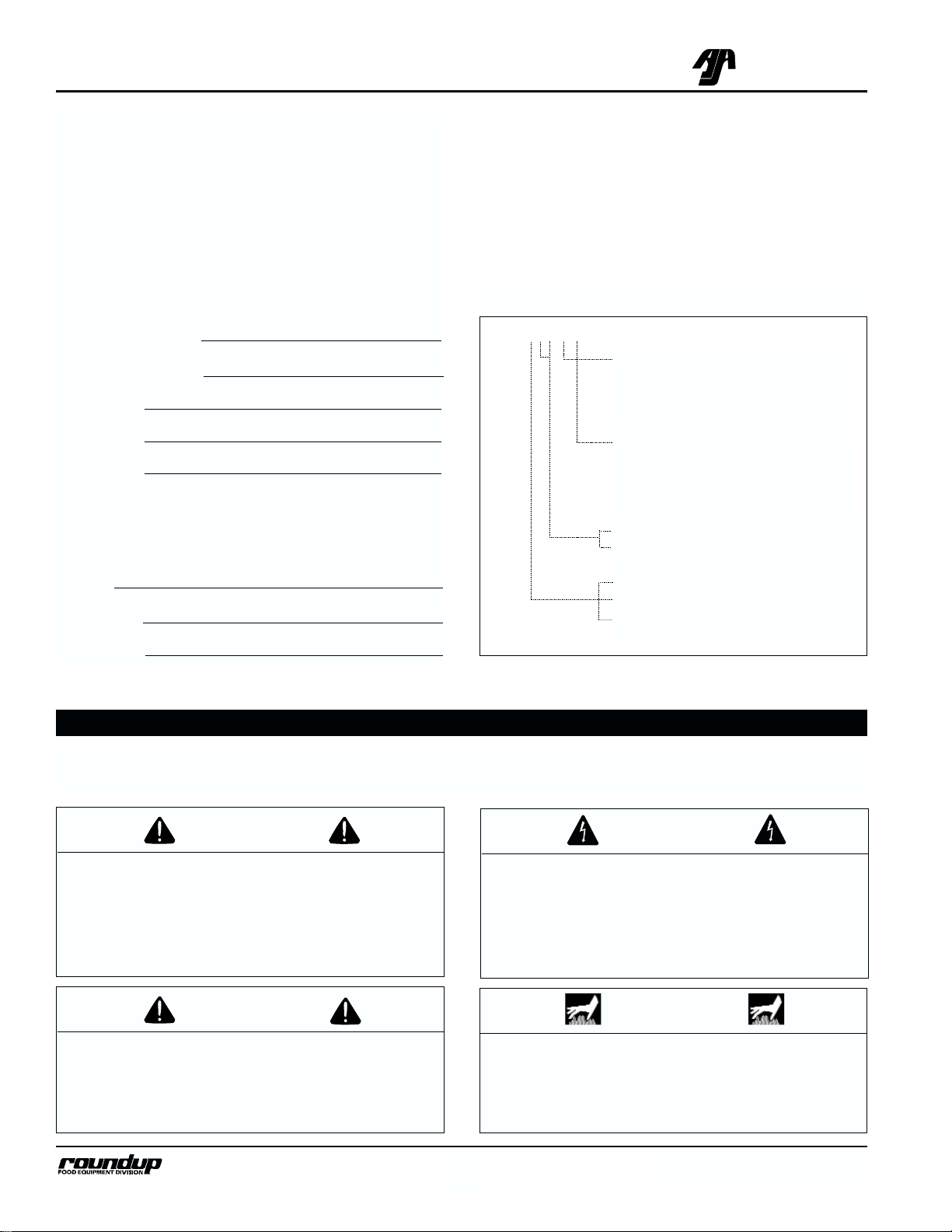
TABLE OF CONTENTS
IMPORTANT! Keep these instructions for future reference. If the unit changes owner-
ship, be sure this manual accompanies the equipment.
If the unit arrives damaged, contact the carrier immediately and file a damage claim with them. Save all
packing materials when filing a claim. Freight damage
claims are the responsibility of the purchaser and are
not covered under warranty.
The warranty does not extend to:
• Damages caused in shipment or damage as
result of improper use.
• Installation of electrical service.
• Normal maintenance as outlined in this manual.
• Malfunction resulting from improper maintenance.
• Damage caused by abuse or careless handling.
• Moisture damage to electrical components.
• Damage from tampering with, removal of, or
changing any preset control or safety device.
IMPORTANT
A.J. Antunes & Co. reserves the right to change specifications and product design
without notice. Such revisions do not entitle the buyer to corresponding changes,
improvements, additions or replacements for previously purchased equipment.
Page 3
WARNING
GENERAL WARNING. Indicates information important to the proper operation of
the equipment. Failure to observe may
result in damage to the equipment and/or
severe bodily injury or death.
Throughout this manual, you will find the following safety words and symbols that signify important safety issues
with regards to operating or maintaining the Miracle Steamer.
WARNING
ELECTRICAL WARNING. Indicates information relating to possible shock hazard.
Failure to observe may result in damage
to the equipment and/or severe bodily
injury or death.
CAUTION
GENERAL CAUTION. Indicates information important to the proper operation of
the equipment. Failure to observe may
result in damage to the equipment.
WARNING
HOT SURFACE WARNING. Indicates
information important to the handling of
equipment and parts. Failure to observe
caution could result in personal injury.
IMPORTANT SAFETY INFORMATION
MIRACLE STEAMER
2
P/N 1010699 Rev. B
A.J. Antunes & Co.
Model Designation
TYPE OF POWER CORD
H = HARMONIZED
C = COMMERCIAL
TYPE OF PLUG
C = CEE 7/7 Schuko
F = NEMA 5-15P
V = NEMA 6-20P
MS-150XX
Service/Technical Assistance
If you experience any problems with the installation or
operation of your unit, contact your local Roundup
Authorized Service Agency. They can be found in the
service agency directory packaged with the equipment.
Fill in the information below and have it handy when
calling your authorized service agency for assistance.
The serial number is on the specification plate located
on the rear of the unit.
Purchased From:
Date of Purchase:
Model No.:
Serial No.:
Mfg. No.:
Refer to the service agency directory and fill in the
information below:
Authorized Service Agency
Name:
Phone No.:
Address:
50 =Timer/Spatula Model
55 = Timer/Drawer Model
1 = Self-Contained Water Tank
2 = Direct Water Hook-Up
3 = Front Water Drawer
Use only genuine Roundup replacement parts in this
unit. Use of replacement parts other than those supplied by the manufacturer will void the warranty. Your
Authorized Service Agency has been factory trained
and has a complete supply of parts for this unit.
You may also contact the factory at 1-877-392-7854 or
1-630-784-1000 if you have trouble locating your local
authorized service agency.
Page 4

MIRACLE STEAMER
3
P/N 1010699 Rev. B
A.J. Antunes & Co.
In addition to the warnings and cautions in this manual,
use the following guidelines for safe operation of the
unit.
• Read all instructions before using equipment.
• For your safety, the equipment is furnished with a
properly grounded cord connector. Do not
attempt to defeat the grounded connector.
• Install or locate the equipment only for its intended use as described in this manual. Do not use
corrosive chemicals in this equipment.
• Do not operate this equipment if it has a damaged cord or plug, if it is not working properly, or
if it has been damaged or dropped.
• This equipment should be serviced by qualified
personnel only. Contact the nearest Roundup
authorized service facility for adjustment or repair.
• Do not block or cover any openings on the unit.
• Do not immerse cord or plug in water.
• Keep cord away from heated surfaces.
• Do not allow cord to hang over edge of table or
counter.
The following warnings and cautions appear
throughout this manual and should be carefully
observed.
• Turn the unit off, disconnect the power source
and allow unit to cool down before performing
any service or maintenance on the unit.
• The equipment should be grounded according
to local electrical codes to prevent the possibility of electrical shock. It requires a grounded receptacle with separate electrical lines,
protected by fuses or circuit breaker of the
proper rating.
• All electrical connections must be in accordance with local electrical codes and any
other applicable codes.
• WARNING ELECTRICAL SHOCK HAZARD.
FAILURE TO FOLLOW THESE INSTRUCTIONS
COULD RESULT IN SERIOUS INJURY OR
DEATH.
- Electrical ground is required on this appliance.
- Do not modify the power supply cord plug.
If it does not fit the outlet, have a proper
outlet installed by a qualified electrician.
- Do not use an extension cord with this
appliance.
- Check with a qualified electrician if you are
in doubt as to whether the appliance is
properly grounded.
• This equipment is to be installed to comply
with the basic plumbing code of the Building
Officials and Code Administrators, Inc.
(BOCA) and the Food Service Sanitation
Manual of the Food and Drug Administration
(FDA).
• If the supply cord is damaged, it must be
replaced by the manufacturer or its service
agent, or a similarly qualified person.
• Do not clean this appliance with a water jet.
• Do not use a sanitizing solution or abrasive
materials. The use of these may cause damage to the stainless steel finish.
• To ensure proper steaming characteristics,
some mineral deposits must be present on
generator casting. If, during cleaning, the
casting does become free of mineral deposits,
one approved method is to add plain tap
water to casting and allow it boil off. This will
ensure proper steaming characteristics by
creating a thin layer of mineral deposits on
the casting.
• Chlorides or phosphates in cleansing agents
(e.g. bleach, sanitizers, degreasers or detergents) could cause permanent damage to
stainless steel equipment. The damage is
usually in the form of discoloration, dulling of
metal surface finish, pits, voids, holes or
cracks. This damage is permanent and not
covered by warranty.
Page 5
MIRACLE STEAMER
4
P/N 1010699 Rev. B
A.J. Antunes & Co.
Voltage Watts Amps Hertz
120 1800 15.0 50/60
208 3300 15.9 50/60
220 3018 13.8 50/60
230 3300 14.4 50/60
240 3592 15.0 50/60
SPECIFICATIONS
Electrical Ratings
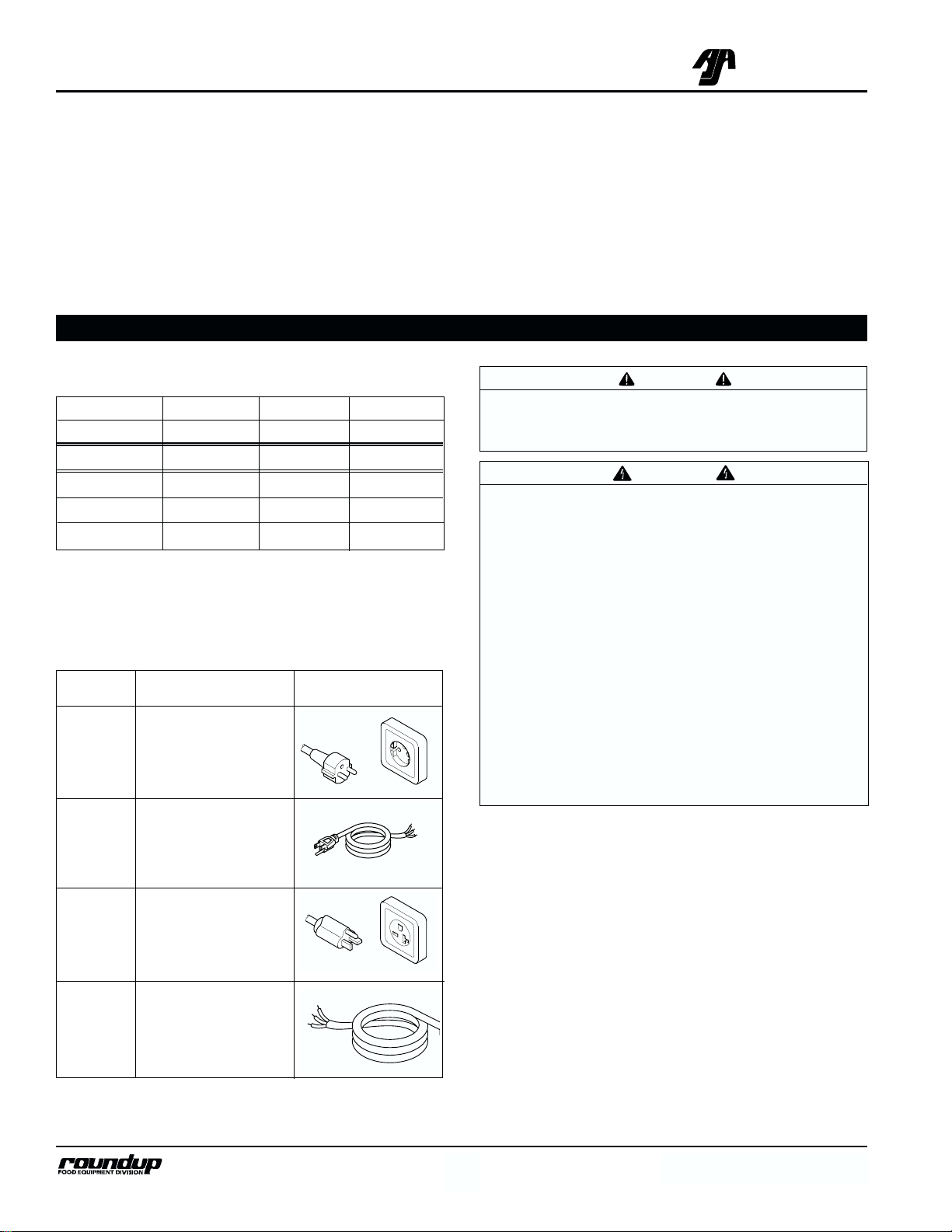
Electrical Cord & Plug Configurations
CAUTION
All electrical connections must be in accordance
with local electrical codes and any other applicable codes.
WARNING
ELECTRICAL SHOCK HAZARD.
FAILURE TO FOLLOW THE INSTRUCTIONS IN
THIS MANUAL COULD RESULT IN SERIOUS
INJURY OR DEATH.
• Electrical ground is required on this appliance.
• Do not modify the power supply cord plug. If it
does not fit the outlet, have a proper outlet
installed by a qualified electrician.
• Do not use an extension cord with this appliance.
• Check with a qualified electrician if you are in
doubt as to whether the appliance is properly
grounded.
Letter Description Configuration
Code*
C CEE 7/7 Schuko
F NEMA 5-15P
V NEMA 6-20P
C Commercial Cord
H Harmonized Cord
* Used in Model Designation
• The following tips are recommended for maintenance of your stainless steel equipment,
- Always use soft, damp cloth for cleaning,
rinse with clear water and wipe dry. When
required, always rub in direction of metal
polish lines.
- Routine cleaning should be done daily
using soap, ammonia detergent and water.
- Stains and spots should be sponged using
a vinegar solution as required.
- Finger marks and smears should be
rubbed off using soap and water.
- Hard water spots should be sponged using
a vinegar solution.
Page 6
MIRACLE STEAMER
5
P/N 1010699 Rev. B
A.J. Antunes & Co.
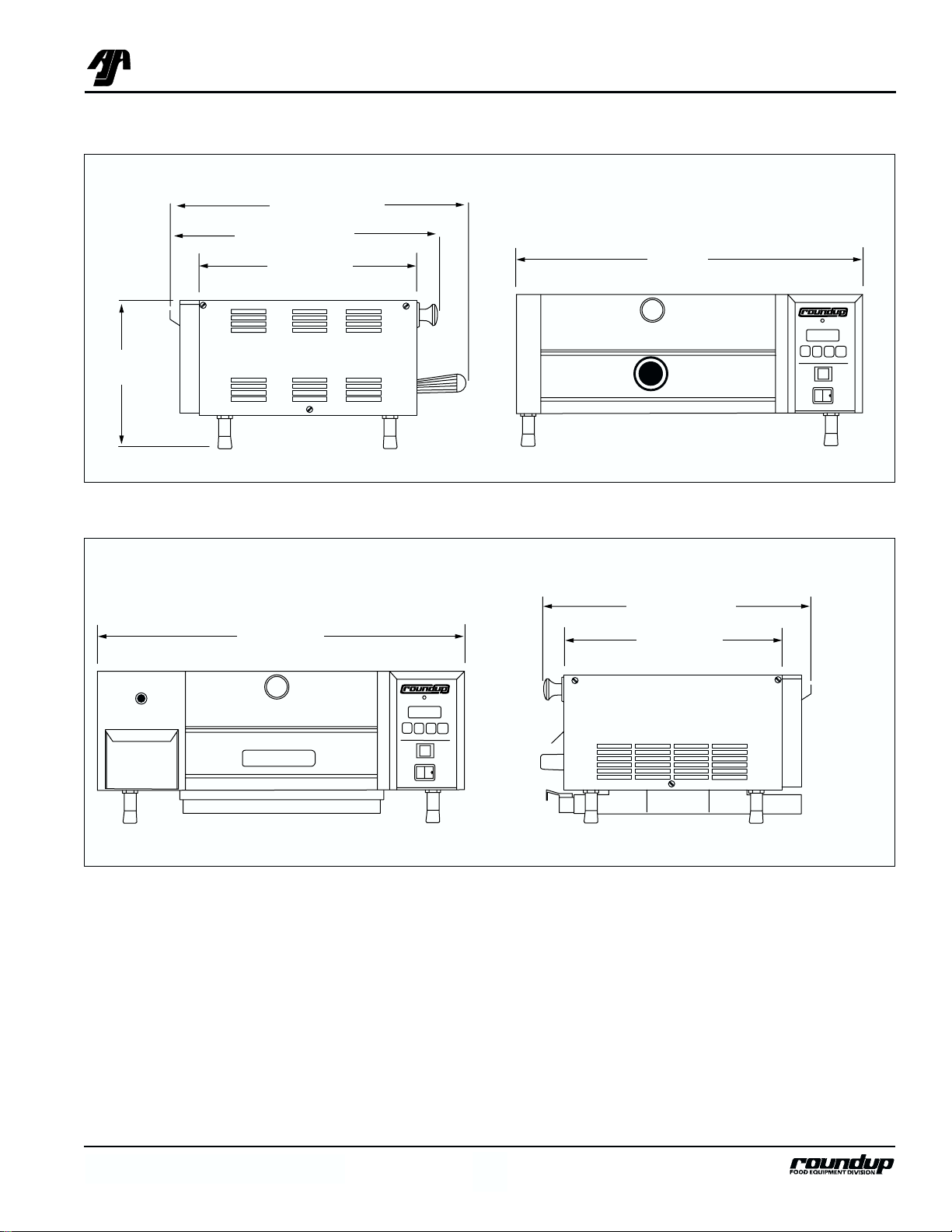
Dimensions
20-3/4"
(52.7 cm)
21-3/16" (53.8 cm)
17-11/32" (28.8 cm)
14" (35.5 cm)
8-13/32"
(21.4 cm)
MS-150/155 & MS-250/255
25" (63.5 cm)
17-5/32" (43.5 cm)
14" (35.5 cm)
MS-355
25"
25"
17-5/32"
14"
Page 7
MIRACLE STEAMER
6
P/N 1010699 Rev. B
A.J. Antunes & Co.
Unpacking
1. Remove unit and all packing materials from shipping carton.
2. Open the large box. It should contain the following:
• Miracle Steamer,
• Handle, Handle Guard & Shoulder Bolt,
(MS-150/250 only)
• Water Hookup Kit (MS-250 only).
NOTE: If any parts are missing or damaged, contact
Antunes Technical Service IMMEDIATELY at 1-877-
392-7854 or 1-630-784-1000.
3. Remove all packing materials and protective coverings from the unit.
4. Remove and wash all removable parts in soap
and water. Rinse with clean hot water and allow
to air dry.
5. Wipe all surfaces of the unit with a hot damp
cloth.
NOTE: Do not use a dripping wet cloth. Wring out
before use.
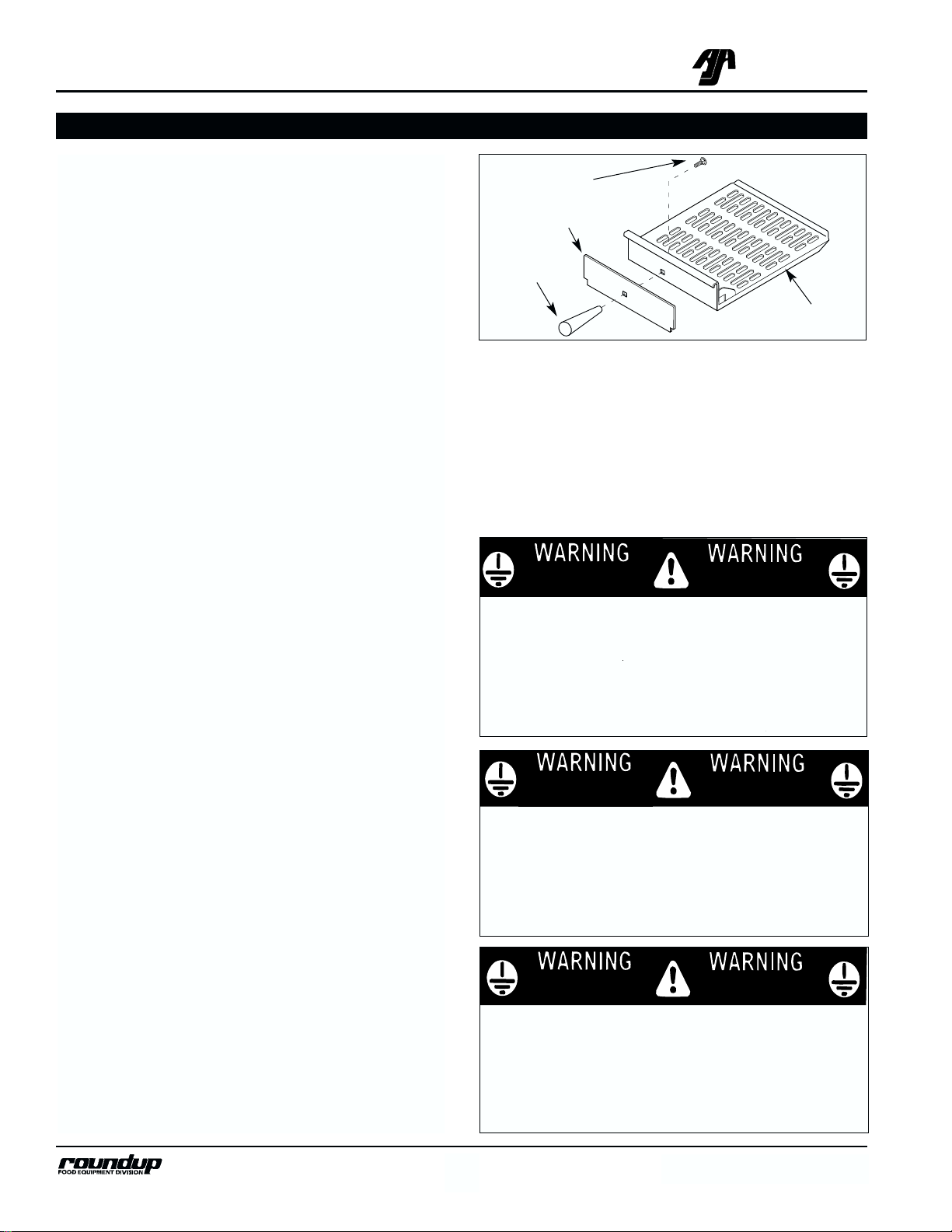
6. MS-150/250 Models: Assemble the handle, han-
dle guard and mounting bolt to the spatula as
shown in Figure 1.
7. Re-install all removed parts.
Equipment Setup
GENERAL
When placing the unit into service, pay attention to the
following guidelines:
• Make sure power to the unit is off and the unit is
at room temperature.
• Do not block or cover any openings on the unit.
• Do not immerse cord or plug in water.
• Keep cord away from heated surfaces.
• Do not allow cord to hang over edge of table or
counter.
ELECTRICAL
1. Place the unit on a sturdy, level table or other
INSTALLATION
Figure 1. Assembling Handle–MS-150/250 Only
Bolt
work surface. Turn the rocker switch (power
ON/OFF to OFF before proceeding.
2. Ensure that the line voltage corresponds to the
stated voltage on the units specification label and
power cord warning tag.
3. Connect the unit to the power supply.
Handle
Spatula
Guard
THIS APPLIANCE MUST BE
THIS APPLIANCE MUST BE
THIS APPLIANCE MUST BE
EARTHED GROUNDED
EARTHED GROUNDED
EARTHED GROUNDED
120 VAC
ONLY
THIS APPLIANCE MUST BE
EARTHED GROUNDED
THIS UNIT IS DESIGNED TO OPERATE
ON 120 VOLTS ONLY. APPLICATION
WITH ANY OTHER VOLTAGE SUPPLY
COMPLETELY VOIDS ALL WARRANTY.
PLEASE CHECK YOUR LINE VOLTAGE
BEFORE INSERTING THIS PLUG INTO
THE RECEPTACLE.
THIS APPLIANCE MUST BE
THIS APPLIANCE MUST BE
THIS APPLIANCE MUST BE
EARTHED GROUNDED
EARTHED GROUNDED
EARTHED GROUNDED
208 VAC
ONLY
THIS APPLIANCE MUST BE
THIS APPLIANCE MUST BE
THIS APPLIANCE MUST BE
EARTHED GROUNDED
EARTHED GROUNDED
EARTHED GROUNDED
220-240 VAC
ONLY
THIS APPLIANCE MUST BE
EARTHED GROUNDED
THIS UNIT IS DESIGNED TO OPERATE
ON 208 VOLTS ONLY. APPLICATION
WITH ANY OTHER VOLTAGE SUPPLY
COMPLETELY VOIDS ALL WARRANTY.
PLEASE CHECK YOUR LINE VOLTAGE
BEFORE INSERTING THIS PLUG INTO
THE RECEPTACLE.
THIS APPLIANCE MUST BE
EARTHED GROUNDED
THIS UNIT IS DESIGNED TO OPERATE
ON 220-240 VOLTS ONLY. APPLICATION
WITH ANY OTHER VOLTAGE SUPPLY
COMPLETELY VOIDS ALL WARRANTY.
PLEASE CHECK YOUR LINE VOLTAGE
BEFORE INSERTING THIS PLUG INTO
THE RECEPTACLE.
Page 8
MIRACLE STEAMER
7
P/N 1010699 Rev. B
A.J. Antunes & Co.
CAUTION
All electrical connections must be in accordance
with local electrical codes and any other applicable codes.
WARNING
ELECTRICAL SHOCK HAZARD.
FAILURE TO FOLLOW THE INSTRUCTIONS IN
THIS MANUAL COULD RESULT IN SERIOUS
INJURY OR DEATH.
• Electrical ground is required on this appliance.
• Do not modify the power supply cord plug. If it
does not fit the outlet, have a proper outlet
installed by a qualified electrician.
• Do not use an extension cord with this appliance.
• The unit should be grounded according to
local electrical codes to prevent the possibility
of electrical shock. It requires a grounded
receptacle with separate electrical lines, protected by fuses or circuit breaker of the proper
rating.
• Check with a qualified electrician if you are in
doubt as to whether the appliance is properly
grounded.
PLUMBING
NOTE: Miracle Steamer models are designed to use
cold tap water. Distilled water may be used to reduce
mineral deposit build-up and reduce maintenance
costs.
CAUTION
This equipment is to be installed to comply with
the basic plumbing code of the Building Officials
and Code Administrators, Inc. (BOCA) and the
Food Service Sanitation Manual of the Food and
Drug Administration (FDA).
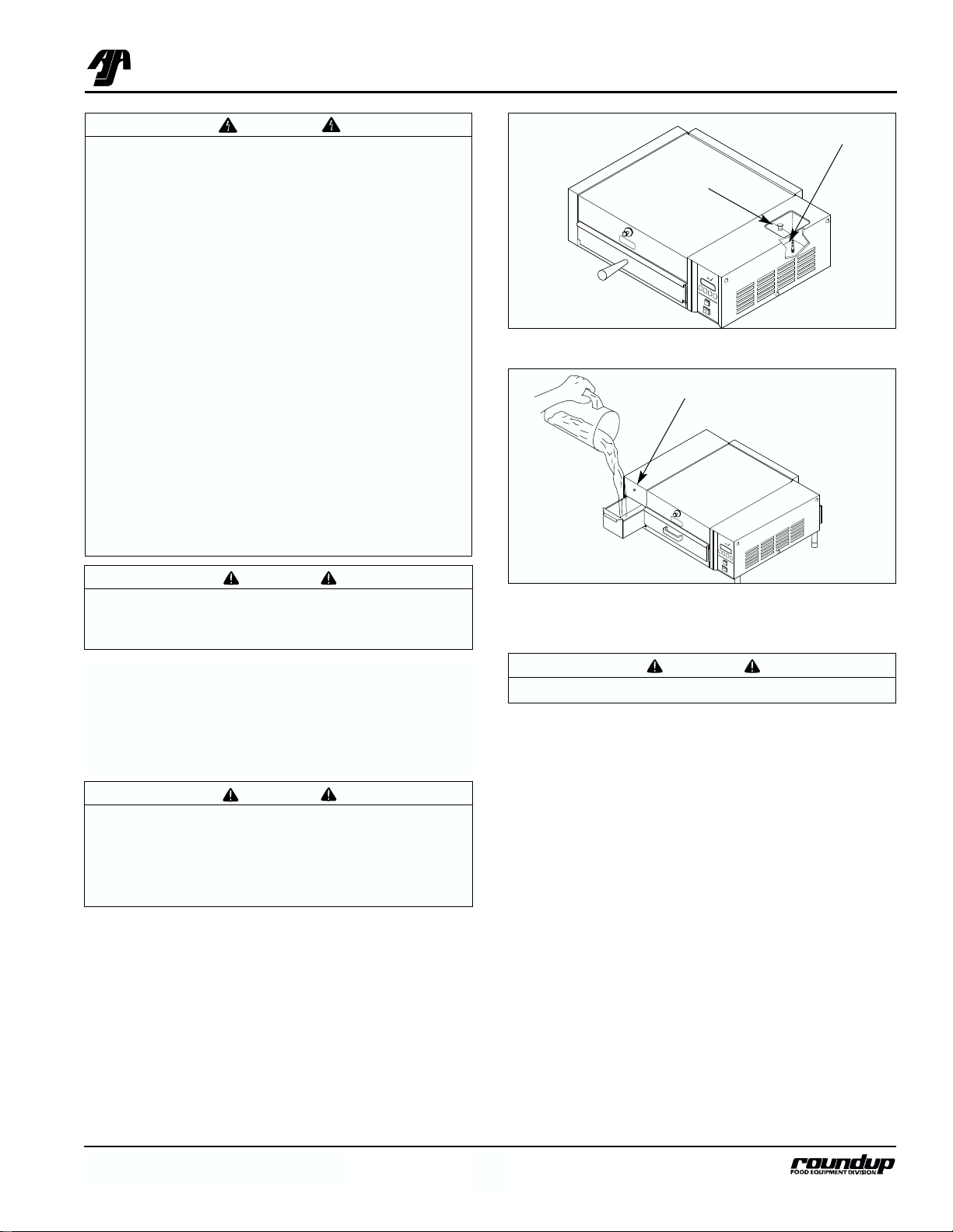
Figure 2. Filling Water Tank–MS-150/155
Filter
Sliding Cover
Figure 3. Filling Water Tank–MS-355
Indicator Light (Low water)
Model MS-150/155 & MS-355
The MS-150/155 & MS-355 models have a self-contained water supply and is portable. To fill the self-contained water tank:
1. MS-150/155: Open the sliding tank cover on top
of the unit (Figure 2).
NOTE: Make sure filter inside tank is installed
properly.
MS-355: Open the sliding tank drawer on the side
of the unit (Figure 3).
2. Pour in cold tap water. The tank will hold approximately 3 quarts (2.81 liters).
3. Close the water tank.
CAUTION
Use cold water only.
R
E
A
D
Y
ADD
WATER
READY
Page 9
MIRACLE STEAMER
8
P/N 1010699 Rev. B
A.J. Antunes & Co.
OPERATION
General
When the operate button (Figure 5) is pressed, power
is supplied to the water pump (MS-150/155/355) or
solenoid (MS-250/255). The pump/solenoid operates
and water sprays onto the heated steam generator.
The water flashes immediately into live steam and
shoots down onto the product.
One of two operational modes can be used: Single
Shot or Timed Cycle
SINGLE SHOT
The operate button is pressed to initiate a single timed
shot. The control board applies power to the water
pump/solenoid and a timed “shot” of steam occurs.
TIMED CYCLE
The control is set to the desired cook time (up to 99
minutes, 59 seconds), then the Start/Stop Button is
pressed. The main control board applies power to the
water pump/solenoid at regular intervals for the duration of the displayed cycle time. The display counts
down to zero when the cycle is complete sounding a
audible signal then reverts back to the original programmed cycle time. The unit is ready for the next
cycle when the green ready light is on.
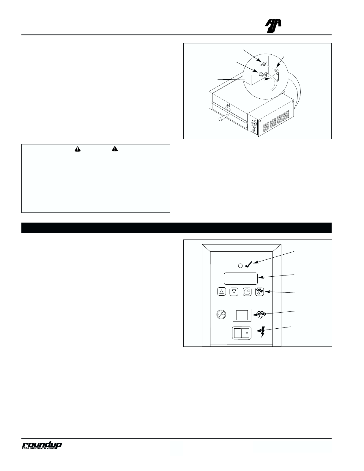
Figure 5. Operating Controls
Ready Light
Rocker Switch
(Power On/Off)
Operate
Button
Message
Display
Start/Stop
Button
CAUTION
Water pressure must not exceed 25 psi (1.7
kg/cm2or 172 kPa). Higher water pressures may
cause poor performance or flooding. To reduce
water pressure, install a water pressure regulator,
and set water pressure to 20 psi (1.4 kg/cm
2
or 138
kPa). To order a water pressure regulator from
your authorized service center, order Roundup
part no. 7000235.
Figure 4. Connecting Water Supply to MS-250/255
Hi-Limit Reset Button
Water Connect Fitting
Power Cord
Quick Disconnect
Insert
Model MS-250/255
The MS-250/255 requires a direct water hookup. An
installation kit is packed inside the unit.
1. Connect the 1/4" (6.5 mm) I.D. flexible tubing to
your cold water line using the supplied hose
clamp.
2. Push the quick disconnect insert into the fitting on
the back of the unit (Figure 4).
NOTE: Incoming water is controlled by a solenoid
valve inside the electrical housing of the steamer.
RE
AD
Y
READY
UP DOWN PROGRAM START/STOP
POWER
Page 10

to zero and an audio signal will sound at the end
of the steaming cycle.
6. Remove steamed product.
Programming
CYC (Total Cycle Time)
refers to the total amount of
cooking time set for the product.
SHO (Shot Interval Time)
is the time set between
shots of steam during a complete cycle.
H2O setting (Steam Shot Time)
is used to adjust the
water volume during each pump/solenoid operation, or
“shot” of steam.
The amount of steam produced by your Miracle
Steamer depends on the amount of water sprayed onto
the steam generator.
Flooding of the generator may occur if the H2O ) setting is set too high. To prevent this from occurring, the
Shot Interval Time (SHO) may be increased to allow
more time for generator recovery. Adjustments should
be made to both values to determine the optimum settings for your cooking needs.
To program the control, refer to Figure 6 and use the
following procedure in sequence:
1. Turn the rocker switch (power on/off) to ON. The
display will show the factory programmed
(default) Total Cycle Time in minutes/seconds
(Item A, Figure 6).
2. Depress the program button to change the control
from OPERATION to PROGRAM mode.
3. To change the Total Cycle Time factory settings
(default), use the UP or DOWN arrow buttons to
change the Total Cycle time in minutes (Item B,
Figure 6).
4. Depress the program button again, and use the
UP or DOWN arrow buttons to change the Total
Cycle Time in seconds (Item C, Figure 6).
5. To change the SHO factory settings (default),
make sure the control is in PROGRAM mode,
then depress the two arrow buttons simultaneously. SHO will be displayed (Item D, Figure 6).
MIRACLE STEAMER
9
P/N 1010699 Rev. B
A.J. Antunes & Co.
IMPORTANT: Your 208V and/or 220-240V Miracle
Steamer is factory programmed for the following settings:
• Total Cycle Time (CYC) = 15 minutes
(Range: 3 secs to 99 mins 59 secs)
• Shot Interval Time (SHO) = 20 seconds
(Range: 3 secs to 5 mins 59 secs)
• Steam Shot Time (H
2
O) =
MS-150/155/355 - (1_00) or 1.00 sec
MS-250/255 - (0_70) or 0.70 sec
(Range: 0.10 sec to 2.50 sec)
This converts approximately 3/4 oz. (25 milliliters) of
water to steam every 20 seconds for a 15 minute cooking cycle. To change any of these settings see
PRO-
GRAMMING
on this page
.
IMPORTANT: Your 120V Miracle Steamer is factory
programmed for the following settings:
• Total Cycle Time (CYC) = 2 minutes
(Range: 3 secs to 99 mins 59 secs)
• Shot Interval Time (SHO) = 20 seconds
(Range: 3 secs to 5 mins 59 secs)
• Steam Shot Time (H
2
O) =
MS-250/255 - (0_40) or 0.40 sec
(Range: 0.10 sec to 2.50 sec)
Operating Instructions
1. Turn the rocker switch (power on/off) to ON (Figure 5).
2. Allow the unit to preheat for approximately 20-30
minutes.
NOTE: Do not push the operate button during warmup time. The flashing green ready light indicates the
unit is NOT up to temperature.
NOTE: The flashing green ready light will become
STEADY when the unit is up to temperature.
3. Pull out the spatula and place the product to be
steamed onto the spatula.
4. Push the spatula fully into the steamer.
5. Single Shot: Press and release the operate button, wait 20 seconds for the steam to penetrate
the product.
Timed Cycle: Press the start/stop button to begin
the steaming cycle. The display will count down
WARNING
To avoid injury, be careful when pulling spatula
out from unit. Be sure to allow steam to escape
before putting hands or face over the steamer.
Page 11

MIRACLE STEAMER
10
P/N 1010699 Rev. B
A.J. Antunes & Co.
Figure 6. Control Programming Sequence
READY
UP DOWN PROGRAM START/STOP
POWER
15
READY
UP DOWN PROGRAM START/STOP
POWER
00
READY
UP DOWN PROGRAM START/STOP
POWER
sho
READY
UP DOWN PROGRAM START/STOP
POWER
00
READY
UP DOWN PROGRAM START/STOP
POWER
20
READY
UP DOWN PROGRAM START/STOP
POWER
H20
READY
UP DOWN PROGRAM START/STOP
POWER
0 70
NOTE: Use the UP or DOWN Arrow Buttons to change the minute or second time interval.
6. Depress the program button once and use the
UP or DOWN arrow buttons to change the SHO
(Shot Interval Time) in seconds (Item E, Figure
6).
NOTE: 20 seconds is recommended.
7. Depress the program button again and use the
UP or DOWN arrow buttons to change the SHO
(Shot Interval Time) in minutes (Item F, Figure 6).
NOTE: 20 seconds is recommended.
8. Depress the program button again and H2O will
be displayed (G, Figure 6).
9. To change the H
2
O (Steam Shot) factory settings
(default), depress the program button again to
display the default setting (Item H, Figure 6). Use
the UP or DOWN arrow buttons to increase or
decrease the time.
A. Default Setting
B. Total Cycle Minutes
C. Total Cycle Seconds
D. SHO Cycle
E. SHO Time in Seconds
F. SHO Time in Minutes
G. H
2
O Cycle
H. H
2
O Default Setting
NOTE: Recommended settings are:
MS-250/255 - [0_40] or 0.40 sec (120 VAC)
MS-250/255 - [0_70] or 0.70 sec (208-240 VAC)
MS-150/155/355 - [1_00] or 1.00 sec (208-240 VAC)
10. Press the Start/Stop button to store the changes,
exit the PROGRAM Mode and initiate the cooking
cycle.
NOTE: The Start/Stop button may be pressed at any
time during programming to store the changes and exit
the PROGRAM Mode.
NOTE: If no change is made within 10 seconds at any
time during the programming process, all changes
made up to that point are stored in memory and the
control reverts to the OPERATION Mode.
READY
1500
UP DOWN PROGRAM START/STOP
POWER
Page 12

MIRACLE STEAMER
11
P/N 1010699 Rev. B
A.J. Antunes & Co.
Steaming Tips
• Pre-cooked pasta is easily reconstituted, and gives
you a hot product without the wetness of the normal “dip” method.
• Experiment with your products and different steaming times–a little more or less steam could change
the appearance/flavor.
• If you serve melted cheese on sandwiches, steam
is the perfect way to melt cheese.
• A steamed bun (which takes about 10-15 seconds)
says “Hot Sandwich” to your customer.
• Vegetables, rice and bread products can be reconstituted by steaming before serving which reduces
waste.
• Dinner rolls, muffins, even tortillas can be heated
completely and held without drying out the product.
• Use a low plate or pan when steaming to allow full
steam penetration and shorter cooking times.
• Use the “1 in 20” rule: Push the operate switch for
one second every twenty seconds. This will ensure
that the product gets fully heated without using
excess water or energy.
• Condensation inside the steamer is normal, but
excess moisture indicates too much water is being
used. Use the “1 in 20” rule above to correct this
problem. Also, examine the steam generator, it may
require cleaning.
• Heat meat and bread products apart from each
other, then combine in a sandwich. This will keep
the meat juices from soaking the bread.
Figure 7. Hi-Limit Reset Button (MS-150 shown)
• Finish off a special meal with a steamed hand
towel–hot without excess moisture.
Hi-Limit Reset Button
A hi-limit thermostat will turn off electrical power to the
heater if the unit overheats. To reset this thermostat,
allow sufficient time (about 45 minutes) for the unit to
cool down, remove the cap and then fully depress the
reset button located on the rear of the unit (Figure 7).
If the unit requires continuous resetting, contact your
Roundup authorized service agency.
Hi-Limit Reset Button
Power Cord
Cap
R
E
A
D
Y
Page 13

MIRACLE STEAMER
12
P/N 1010699 Rev. B
A.J. Antunes & Co.
Daily
1. Turn the rocker switch (power on/off) to OFF.
Unplug the power cord and allow the unit to cool
down before proceeding.
2. Check the water quick disconnect fitting (MS-250)
and all hose clamps connections for leakage. If
leakage is apparent, tighten all clamps or replace
part if required.
3. Remove drawer (MS-155/255 & 355) or spatula
trivvet (MS-150 & 250) and liner (Figure 8).
4. Remove steam vent from rear of unit by sliding
upward and away from unit (Figure 8). Clean the
drawer/spatula and steam vent in hot detergent
water, rinse in clear water and allow to air dry.
5. Clean the chamber of any product spills.
6. Clean entire unit with a clean, hot, damp cloth
(not dripping wet) and wipe dry.
7. Re-install components.
NOTE: Install steam vent before installing liner and
drawer/spatula.
Monthly
Your Miracle Steamer utilizes an open steam generator. Water sprayed onto the generator surface flashes
into steam immediately, but the minerals in the water
do not steam, they stay on the generator surface. A
small amount of mineral deposits are needed for proper operation, but a build-up of excessive mineral
deposits causes poor steaming efficiency, excessive
moisture (wet steam) and will eventually severely
retard the steaming action completely.
Cleaning Steam Generator
1. Turn the rocker switch (power on/off) to OFF.
Unplug the power cord and allow the unit to cool
down before proceeding.
2. Remove top cover from unit.
3. Remove wing nut and generator cover (Figure 8).
4. Remove the diffuser.
MAINTENANCE
WARNING
Turn the unit off, disconnect the power source
and allow the unit to cool down before performing
any service or maintenance on the unit.
CAUTION
Chlorides or phosphates in cleansing agents (e.g.
bleach, sanitizers, degreasers or detergents)
could cause permanent damage to stainless steel
equipment. The damage is usually in the form of
discoloration, dulling of metal surface finish, pits,
voids, holes or cracks. This damage is permanent
and not covered by warranty. The following tips
are recommended for maintenance of your stainless steel equipment:
• Always use soft, damp cloth for cleaning, rinse
with clear water and wipe dry. When required,
always rub in direction of metal polish lines.
• Routine cleaning should be done daily using
soap, ammonia detergent and water.
• Stains and spots should be sponged using a
vinegar solution.
• Finger marks and smears should be rubbed off
using soap and water.
• Hard water spots should be sponged using a
vinegar solution.
NOTE: Frequency of cleaning is determined by water
conditions, usage and water filtration systems.
CAUTION
Do not use a sanitizing solution or abrasive materials. The use of these may cause damage to the
stainless steel finish.
CAUTION
If a chemical cleaner is used, be sure it is safe to
use on cast aluminum. Observe all precautions
and warnings on product label.
CAUTION
Unplug power cord before moving and servicing
this appliance.
Page 14

MIRACLE STEAMER
13
P/N 1010699 Rev. B
A.J. Antunes & Co.
11. Clean unit surface with a hot, clean, damp cloth
(not dripping wet) and wipe dry.
12. Re-install all parts and fasten the generator cover.
NOTE: To ensure proper steaming characteristics,
some mineral deposits must be present on generator
casting. If during cleaning, the casting does become
free of mineral deposits, add plain tap water to casting
and allow to boil off.
NOTE: In soft water areas, it may be necessary to add
a small amount of lime to generator to “season” it. This
will ensure proper steaming characteristics by producing a thin coating of mineral deposits on the casting.
Seasoning mixture consists of 2 ounces (59.15 milliliters) baking soda, 2 ounces (59.15 milliliters) lime
mixed with 2 ounces (59.15 milliliters) of warm tap
water.
Pour the seasoning mixture into the bowl portion of the
generator, turn the steamer rocker power (on/off) to
ON. Once the mixture has boiled off, remove the
remaining loose powder.
13. Plug in power cord and water line (if applicable).
Figure 8. Miracle Steamer Components
ADD
WATER
Spatula (MS-150/250 only)
Liner (MS-150/250 only)
Drip Pan (MS-155/255/355 only)
Liner (MS-155/255/355 only)
Drawer (MS-155/255/355 only)
Top Cover
Wingnut
Cover
Diffuser
Steam Vent
MS-355 Shown
5. Examine all generator orifices (holes). If mineral
deposits have formed, place a flat blade screwdriver into openings. Use a gentle twisting
motion to scrape openings clean.
NOTE: If the mineral deposits come off in “flakes” or in
layers, build-up is excessive.
6. Use a brass or stainless steel wire brush to
remove deposits from the generator surface.
7. Pour a delimer solution (not supplied) onto the
generator surface and allow to soak for one hour.
Be sure to follow the delimer manufacturer’s
directions for proper mixture and use.
NOTE: Use only a Aluminium safe de-liming product.
8. Remove the delimer solution from the generator
and rinse with clear water to remove traces of
delimer.
9. Clean the following parts in hot detergent water,
then rinse in clear water and allow to air dry:
• spatula/drawer • top cover
• liner • steam vent
• generator cover • diffuser
10. Clean steam chamber of any product spills.
ADD
WATER
READY
Page 15

MIRACLE STEAMER
14
P/N 1010699 Rev. B
A.J. Antunes & Co.
Figure 9. Water Filters–MS-150/155
Top Water Filter
Bottom Water Filter
Water Filters–Models MS-150/155
To prevent solids or food products from entering the
water pump, the unit uses two water filters (Figure 9).
Inspect and clean (if necessary) these filters monthly
using the following procedure:
1. Turn the rocker switch (power on/off) to OFF.
Unplug the power cord and allow the unit to cool
down before proceeding.
2. Remove access cover and tank assembly.
3. Drain water from access cover/tank assembly by
sliding tank assembly cover open, tip assembly
and pour water into a container or sink.
4. Remove top filter located inside the tank by
pulling it out (Figure 9).
5. Remove bottom filter located in water tank outlet
tube by disconnecting the hose from the outlet
and removing filter (Figure 9).
6. Clean filters by running them under tap water.
Replace them if they are torn or damaged.
7. Install bottom filter inside the water outlet tube.
Install outlet hose and clamp.
8. Install top filter into water outlet tube inside the
tank.
9. Install access cover and tank assembly.
10. Fill water tank and test unit.
NOTE: The MS-355 does not use a water filter.
Direct water hook-up Units (MS-250/255)
Use of the optional water regulator kit, part no.
7000235, is recommended (see page 25).
Page 16

MIRACLE STEAMER
15
P/N 1010699 Rev. B
A.J. Antunes & Co.
Unit will not heat up. Rocker
(power on/off) switch is ON.
Unit heats up but will not
steam.
or
Steam product unevenly.
or
Requires multiple cycles to
melt cheese or otherwise
prepare the product.
Unit is not plugged in.
Loose connections.
Circuit breaker is off or has been
tripped in main power supply.
Defective wiring.
Inoperable power cord.
Hi-Limit thermostat tripped or
inoperable (see page 11).
Inoperable heater relay.
Inoperable generator.
Restrictor tube and/or generator
tubes are clogged.
Low water pressure.
Diffuser is missing.
Water filters clogged.
Loose electrical connection at water
pump/solenoid valve, or inoperable
water solenoid valve.
Defective momentary switch.
Plug power cord into outlet.
Check connectivity of the power cord and
connector.
Turn on or reset circuit breaker.
Contact maintenance or AJA Authorized
Service Center.
Inspect for burned or worn prongs and connector. Contact maintenance. or AJA
Authorized Service Center.
Contact maintenance or AJA Authorized
Service Center.
Contact maintenance or AJA Authorized
Service Center.
Contact maintenance or AJA Authorized
Service Center.
Clean restrictor tube and/or generator
tubes.
*(Units with regulators) Verify pressure is
set to 20 psi (138 kPa).
Re-install the diffuser.
Remove filters and clean.
Contact maintenance or AJA Authorized
Service Center.
Contact maintenance or AJA Authorized
Service Center.
Problem Possible Cause Corrective Action
TROUBLESHOOTING
WARNING
To avoid possible personal injury and/or damage to the unit, inspection, test and repair of electrical equipment should be performed by qualified service personnel. The unit should be unplugged when servicing,
except when electrical tests are required.
Page 17

MIRACLE STEAMER
16
P/N 1010699 Rev. B
A.J. Antunes & Co.
Steam from generator is
reduced compared to former
operation.
Unit becomes flooded or
always steaming. Power
ON, solenoid makes a chattering noise.
or
Unit floods overnight. Power
OFF.
Water leaking in the
electrical housing.
Restrictor tube or generator tubes are
clogged.
Flooding condition.
Insufficient preheat.
Filters require cleaning.
Control board setpoint temperature
too low.
Heavy deposit buildup on the generator.
Incorrect water pressure.
Solenoid valve inoperable or particles
in the valve.
Control board is not programmed
properly.
Control board is inoperable.
Pin hole leak in the hoses.
Inlet tube or restrictor tube is loose.
Generator tube is loose or damaged.
Clean restrictor tube and/or generator
tubes.
Allow 20 minutes for excess water to evaporate and generator to recover to 375°F.
Allow excess water on the generator casting
to evaporate and preheat 20 minutes before
operating. DO NOT operate steamer during
preheat cycle.
See page 14.
Surface temperature of the casting should
be between 375°- 425° F (191°- 218°C)
when the red light on the control board
turns off. If the temp is too low, contact
maintenance or AJA Authorized Service
Center.
See maintenance procedure under
Cleaning
Generator.
*(Regulated units only.) Set water pressure
to 20 psi (138 kPa).
May need to cleaned or replaced. Contact
maintenance or AJA Authorized Service
Center.
Verify programming as described in the
Programming
section.
Contact maintenance or AJA Authorized
Service Center.
Replace the hoses.
Tighten the loose fittings.
Tighten loose fittings or contact maintenance or AJA Authorized Service Center.
Problem Possible Cause Corrective Action
Page 18

MIRACLE STEAMER
17
P/N 1010699 Rev. B
A.J. Antunes & Co.
Unit heats up, pump or solenoid valve works with the
momentary switch but will
not steam during timer
cycles.
Steam coming out around
top covers or sides.
Programming.
If Ready light does not light but the
unit steams regularly, the Ready light
is inoperable.
If the Ready light does light and the
unit does not steam, the control board
is inoperable.
*(Direct Feed Units) Quick-disconnect
not connected properly or inoperable.
Water volume adjustment is too low.
Water filter clogged.
Inoperable solenoid or solenoid damage caused by connecting a hot
water supply line.
Inoperable control board.
Wingnut is loose.
Generator cover damage.
See pages 8-10.
Contact maintenance or AJA Authorized
Service Center.
Contact maintenance or AJA Authorized
Service Center.
Make sure the quick-disconnect and O-ring
are properly positioned and are not damaged. Replace damaged parts.
Adjust the water volume control. See
Calibration
section of the manual.
Remove and clean filter.
Make sure unit is connected to a cold water
supply. Contact maintenance or AJA
Authorized Service Center.
Contact maintenance or AJA Authorized
Service Center.
Tighten wingnut.
Adjust or replace generator cover.
Problem Possible Cause Corrective Action
Page 19

MIRACLE STEAMER
18
P/N 1010699 Rev. B
A.J. Antunes & Co.
REPLACEMENT PARTS
MS-150/155/250/255
64
17
74
18
36
73
21
16
57
11
53
10
20
53
9
6
66
R
E
A
D
Y
15
57
53
41
42
75
7
62
37
13
12
6
24
70
87
86
80
82
83
84
65
85
79
81
81
35
88
3
89
85
Page 20

MIRACLE STEAMER
19
P/N 1010699 Rev. B
A.J. Antunes & Co.
1 0010159 Filter Assy., Water Tank (MS-150) 1
2 4050125 Relay 1
3 0010584 Inlet Hose Assy. (MS-250) 1
4 0011114 Pump/Tube Assy., 24V (MS-150) 1
5 0011123 Solenoid Valve Assy. (MS-250) 1
6 0011289 Top Cover Assy. 1
7 0011314 Chimney Assy. 1
8 0021131 Floor/Chassis Weldment 1
9 0021179 Access Cover Weldment (MS-150) 1
10 0100217 Generator, 230V 1
0100218 Generator, 208V 1
0100233 Generator, 120V 1
11 0300129 Stud, Cover Hold Down 1
12 0400138 Locknut, 1/2" 1
13 0400251 Strain Relief 1
14 0502199 Spacer 2
15 0503431 Diffuser, Steam 1
16 0503432 Bracket, Filler 1
17 0503433 Cover, Generator 1
18 0503434 Cover, End Housing 1
19 0503435 Retainer, Thermocouple 1
20 0503867 Spatula (MS-150/250 only) 1
21 0503440 Liner, Cavity (MS-150/250 only) 1
22 0503441 Access Cover (MS-250) 1
23 0503472 Bracket, Hi-Limit Support 1
24 0700452 Power Cord, NEMA 6-20P 1
25 0800359 Trivet, Spatula (MS-150/250 only) 1
26 1000967 Label, Marking 1
27 1001036 Label, Control Panel 1
28 2000203 Tube, Restrictor, 1/4" 1
29 2000207 Tube, Inlet,
1/4 x 2-1/2" Long (MS-250) 1
30 2040103 Connector, Male,
1/4 x 1/8 NPT (MS-250) 1
31 2040106 Adapter, Tube/Hose (MS-150) 1
32 2040145 Elbow, Female, 1/8" x 1/4" 1
33 2040146 Tee, Female, 1/8" x 1/4" 1
34 2090101 Filter, Water Line (MS-150) 1
35 2100109 Foot, Rubber 2
36 2100119 Handle, Spatula (MS-150/250 only) 1
37 4050180 Heat Sink 1
39 2100170 Knob, Chrome (MS-150) 1
41 2100250 Guard, Knob 1
42 2100273 Knob 1
43 2110101 Clamp, Hose, 3/8 (MS-150) 1
44 2110103 Clamp, Hose, 1/2" (MS-150) 1
46 2190102 Generator Tube, Teflon, 4-1/2" Lg.
(MS-250) 1
47 2190105 Generator Tube, Teflon (MS-150) 2
48 300P102* Nut, Speed, "U", #8-32 2
49 304P105* Nut, Hex, KEPS, #4-40, Zinc 4
50 306P101* Nut, Hex, #6-32 2
51 306P105* Screw, Machine, #6-32 x 1/2"
(MS-150) 2
52 306P123* Screw, Machine, #6-32 x 7/8" 2
53 306P130* Nut, Hex, KEPS, #6-32 2
54 306P134* Screw, Machine, #6-32 x 3/8 3
55 308P103* Screw, Machine, #8-32 x 1/4"
(MS-150) 6
56 308P103* Screw, Machine, #8-32 x 1/4"
(MS-150) 19
57 308P105* Screw, Machine, #8-32 x 1/2" 4
58 308P120* Screw, Machine,
#8-32 x 5/8" (sltrshd) 4
59 308P124* Screw, Machine,
#8-32 x 1/2" (one-way) 1
60 308P143* Nut, Hex, KEPS, #32-1/2" 2
61 310P136* Screw, Machine,
#10-32 x 1-1/4"(splanhd) 4
62 310P149* Screw, Machine,
#10-32 x 7/8" (MS-250) 2
63 310P149* Screw, Machine,
#10-32 x 7/8" (MS-150) 2
64 325P170* Nut, Wing, 1/4-20 1
65 4010137 Rocker Switch, Power On/Off
25A-250V 1
66 4010166 Switch, Momentary 1
67 4010183 Transformer, 115-230/24V 1
68 4030314 Thermostat, Hi-Limit 1
69 4050209 Thermocouple, Type-K 1
70 4060107 Cable Tie 3
71 4060304 Terminal Block, 3-Pole 1
72 4070037 Control Board,
Temperature/Timer, 24V, 50/60 Hz 1
73 2100240 Guard, Handle (MS-150/250 only) 1
74 338P102* Bolt, Handle Mounting
(MS-150/250 only) 1
75 325P109* Bolt, 1/4"-20 x 1/2" 2
76 7000170 Water Pump Valve Kit
(Includes 77 & 78) 1
77 4040108 Valve, Discharge Side (white) 1
78 4040148 Valve, Intake Side (clear) 1
79 0011414 Drawer Assy. (Incl. #81-87)
(MS-155/255 only) 1
80 0021238 Drawer Weldment
(MS-155/255 only) 1
81 2100195 Bearing, Roller, SS
(MS-155/255 only) 4
82 2100257 Handle (MS-155/255 only) 1
83 2100264 Guard, Handle (MS-155/255 only) 1
84 325P132* Screw, Machine, 1/4-20 x 1/2"
(MS-155/255 only) 2
85 0502291 Spacer (MS-155/255 only) 2
86 306P107* Stud, PEM, #6-32 x 3/8" (
MS-155/255 only) 2
87 306P137* Acorn Nut, #6-32 (MS-155/255 only) 2
88 0021237 Liner Weldment (MS-155/255 only) 1
89 0503536 Drip Pan 1
* Only available in quantities of 10.
Item Part No. Description Qty.
Item Part No. Description Qty.
MS-150/155/250/255
Page 21

MIRACLE STEAMER
20
P/N 1010699 Rev. B
A.J. Antunes & Co.
MS-150/155/250/255
NOTE: Refer to parts list on page 19.
REA
DY
A
INSET A (Model MS 150)
76
77
INSET B (Model MS 150)
1
39
9
34
43
78
43
B
INSET C (Model MS 150)
48
55
72
READY
46
67
C
32
23
49
49
C
4
28
47
71
26
56
46
33
43
31
54
68
51
58
59
C
B
2
37
69
A
27
61
60
C
19
54
Page 22

MIRACLE STEAMER
21
P/N 1010699 Rev. B
A.J. Antunes & Co.
NOTE: Refer to parts list on page 19.
MS-150/155/250/255
READY
INSET B (Model MS 250)
48
72
67
49
26
47
71
56
66
61
22
55
INSET A (Model MS 250)
5
28
32
58
45
14
2
23
37
55
A
45
30
29
33
54
27
READY
60
19
A
59
69
54
Page 23

MIRACLE STEAMER
22
P/N 1010699 Rev. B
A.J. Antunes & Co.
1 0011314 Steam Vent Assy. 1
2 0011408 Top Cover Assy. (Incl. #73-77) 1
3 0011413 Liner Assy. (Incl. #65, 69, 72) 1
4 0011414 Drawer Assy. (Incl. #64-71) 1
5 0011416 Main Housing Assy. 1
0011418 Main Housing Assy. 1
6 0400138 Locknut, Conduit, 1/2" 1
7 0400251 Strain Relief 1
8 0503441 Cover, Access 1
9 0503536 Drip Pan, Water 1
10 0503712 Cover, Tank Housing 1
11 0700452 Power Cord, NEMA 6-20P 1
12 4050125 Relay 1
13 1001066 Label, Wiring Diagram 1
14 4070037 Control Board, 24V, 50/60 Hz 1
15 4050180 Heat Sink 1
16 0011370 Leg Assy., 2" 4
17 0021241 Channel Weldment 1
18 0021242 Floor/Chassis Weldment 1
19 0100218 Generator, 208V 1
0100217 Generator, 230V 1
20 0011447 Float Switch Assy. 1
21 0300129 Stud, Cover 1
22 0400119 Bushing, Shorty, 3/8" 4
23 0500281 Bracket, Pump Mounting 2
24 0502199 Spacer 2
25 0503429 Support, Generator, Upper 1
26 0503431 Diffuser 1
27 0503433 Cover, Generator 1
28 0503435 Retainer, Thermocouple 1
29 0503472 Bracket, Hi-Limit Thermostat Support 1
30 0503713 Guard, Wire 1
31 0700600 Wire Set (not shown) 1
32 1001036 Label, Control Panel 1
33 2000203 Tube, Restrictor, 1/4" 1
34 2000208 Tube, Supply 1
35 2040106 Adapter, Tube/Hose 1
36 2040145 Elbow, Female, 1/8" x 1/4" 1
37 2040146 Tee, Female, 1/8" x 1/4" 1
38 2110101 Clamp, Hose, 3/8" 2
39 2110103 Clamp, Hose, 1/2" 2
40 218P112* Nut, Nylon, 1/2-13 2
41 2190111 Pipe, Teflon, 3-5/8" Long 2
42 300P102* Nut, Speed, "U", #8-32 2
43 304P105* Nut, Hex, KEPS, #4-40, Zinc 4
44 306P101* Nut, Hex, #8-32 2
45 306P123* Screw, Machine, #6-32 x 7/8" 2
46 306P134* Screw, Machine, #6-32 x 3/8" 3
47 308P103* Screw, Machine, #8-32 x 1/4" 20
48 308P105* Screw, Machine, #8-32 x 1/2" 4
49 308P120* Screw, Machine, #8-32 x 5/8" 2
50 308P124* Screw, Machine, One-Way, #8-32 x 1/2"1
51 308P143* Nut, Hex, KEPS, #8-32 8
52 310P110* Screw, Machine, #10-32 x 1/2", SS 4
53 325P170* Wingnut, 1/4-20 1
54 0500229 Retainer 1
55 4010137 Rocker Switch, Power On/Off,
25A-250V 1
56 4010166 Momentary Switch (Single Shot) 1
57 4010183 Transformer, 115-230/24V 1
58 4030314 Thermostat, Hi-Limit 1
59 4040144 Water Pump, Oscillating, 24V 1
60 4050214 Thermocouple, Type-K 1
61 406P107* Cable Tie, 1/8" Wide x 5" Long 3
(not shown)
62 4060304 Terminal Block, 3-Pole 1
63 4060371 Indicator Light, Blue, 12V 1
64 0021238 Drawer Weldment 1
65 2150194 Bearing, Roller, Nylon, SS 4
66 2100257 Handle 1
67 2100264 Guard, Handle 1
68 325P132* Screw, Machine, 1/4-20 x 1/2" 2
69 0502291 Spacer 2
70 306P107* Stud, PEM, #6-32 x 3/8" 2
71 306P137* Acorn Nut, #6-32 2
72 0021237 Liner Weldment 1
73 0503686 Cover, Top 1
74 2100273 Knob 1
75 2100250 Guard, Knob 1
76 390P101* Bolt, M8 x 1.25 x 14mm Long 1
77 1000864 Label, Caution HOT 1
78 0011446 Silicone Tube Assy., 26” 1
79 0020520 Silicone Tube Assy., 13” 1
80 7000170 Water Pump Valve Kit 1
(Incl. #81 & 82)
81 4040108 Valve, Discharge Side (White) 1
82 4040148 Valve, Intake Side (Clear) 1
* Only available in quantities of 10.
Item Part No. Description Qty.
Item Part No. Description Qty.
MS-355
Page 24

MIRACLE STEAMER
23
P/N 1010699 Rev. B
A.J. Antunes & Co.
MS-355
NOTE: Refer to parts list on page 22.
AD
D
WATER
READ
Y
INSET A (Model MS 355)
80
81
38
59
B
79
23
C
36
41
29
INSET C (Model MS 355)
33
14
INSET B (Model MS 355)
82
51
54
34
51
A
DD
W
A
TE
R
63
C
41
B
40
40
17
39
78
43
37
47
35
57
38
79
44
42
62
47
20
45
50
83
24
58
12
A
15
51
READY
22
C
60
32
48
49
49
C
49
28
Page 25

MIRACLE STEAMER
24
P/N 1010699 Rev. B
A.J. Antunes & Co.
ADD
TER
MS-355
NOTE: Refer to parts list on page 22.
47
25
46
53
27
26
47
21
2
66
67
70
71
68
10
19
46
74
77
75
46
25
A
DD
WATE
R
30
76
1
73
11
13
18
5
56
R
EA
D
Y
52
8
16
7
6
61
55
64
69
65
4
9
3
72
69
65
Page 26

MIRACLE STEAMER
25
P/N 1010699 Rev. B
A.J. Antunes & Co.
REPLACEMENT PARTS (continued)
Item Part Description Qty.
No.
1 0503615 Bracket, Manifold 1
2 2030125 Tubing, 1/4" I.D., PVC, 12" Long 2
3 2040150 Elbow, Male, Nylon,
1/4" Barb, 3/8" NPT 2
4 2040151 Nipple, Hex, Nylon, 3/8" x 1/4" NPT 1
5 2080105 Elbow, Quick Disconnect 2
6 2080118 Quick Disconnect, 1/8" NPT 1
7 2170113 Regulator, Pressure 1
8 2170114 Gauge, Water Pressure 1
9 2190113 Manifold 1
10 2110160 Clamp 4
Water Pressure Regulator Kit - Part No. 7000235
To Steamer
Water Supply
To Steamer
5
2
3
8
10
6
1
IMPORTANT: Two steamer units can be connected into
one water pressure regulator.
4
7
9
Page 27

MIRACLE STEAMER
26
P/N 1010699 Rev. B
A.J. Antunes & Co.
WIRING DIAGRAMS
MS-150/155/250/255
MS-355
POWER
CORD
GRN
HT/BLU
BLK/BRN
W
BLK/BRN
BLK
WHT
POWER
SWITCH
GRN-YEL
TERMINAL
BLOCK
GRN
1
4
NOTE: ALL WIRES TO BE 14 GA. AWM–105 C
UNLESS OTHERWISE SPECIFIED.
#18 GA. AWM–105 C
l
22 GA. AWM–105 C
GRD
HEATERHI-LIMIT
BLK
SOLENOID
#WHT
BRN
l
8
BRN
l
6
#BLK
WHT
THERMOSTAT
#WHT
120V
#BLK
5
4
230V
2
1
TRANSFORMER
BLK
WHT
10
S.S. RELAY
3+
2
1
4–
YEL
MOMENTARY
SWITCH
BLU
RED
THERMOCOUPLE
BLU
T2
T1
CONTROL
T3
BOARD
T7
T2
T5
T6
VIO
Page 28

1025 W. National Avenue • Addison, Illinois 60101
Telephone (630) 543-8650 • FAX (630) 543-0359 • 1-800-253-2991
www.ajantunes.com
LIMITED WARRANTY
Equipment manufactured by Roundup Food Equipment Division of A.J. Antunes & Co. has been constructed of the finest
materials available and manufactured to high quality standards. These units are warranted to be free from mechanical
and electrical defects for a period of one year from date of purchase or 18 months from shipment from factory, whichever
occurs first, under normal use and service, and when installed in accordance with manufacturer’s recommendations.
To insure continued proper operation of the units, follow the maintenance procedure outlined in the Owner’s Manual.
1.This warranty does not cover cost of installation, defects caused by improper storage or handling prior to placing of the
Equipment. This warranty does not include overtime charges or work done by unauthorized service agencies or personnel.
This warranty does not cover normal maintenance, calibration, or regular adjustments as specified in operating and maintenance instructions of this manual, and/or labor involved in moving adjacent objects to gain access to the Equipment. This
warranty does not cover consumable items such as platen release sheet and conveyor belt wraps. This warranty does not
pay travel, mileage, or any other charges for an authorized service agency to reach the equipment location.
2.Roundup reserves the right to make changes in design or add any improvements on any product. The right is always
reserved to modify equipment because of factors beyond our control and government regulations. Changes to update equipment do not constitute a warranty charge.
3.
If shipment is damaged in transit, the purchaser should make a claim directly upon the carrier. Careful inspection should
be made of the shipment as soon as it arrives and visible damage should be noted upon the carrier’s receipt. Damage
should be reported to the carrier. This damage is not covered under this warranty.
4.Warranty charges do not include freight or foreign, excise, municipal or other sales or use taxes. All such freight and taxes
are the responsibility of the purchaser.
5.THIS WARRANTY IS EXCLUSIVE AND IS IN LIEU OF ALL OTHER WARRANTIES, EXPRESSED OR IMPLIED, INCLUDING ANY IMPLIED WARRANTY OR MERCHANTABILITY OR FITNESS FOR A PARTICULAR PURPOSE, EACH OF
WHICH IS HEREBY EXPRESSLY DISCLAIMED. THE REMEDIES DESCRIBED ABOVE ARE EXCLUSIVE AND IN NO
EVENT SHALL ROUNDUP BE LIABLE FOR SPECIAL CONSEQUENTIAL OR INCIDENTAL DAMAGES FOR THE
BREACH OR DELAY IN PERFORMANCE OF THIS WARRANTY.
A.J. ANTUNES & CO.
 Loading...