

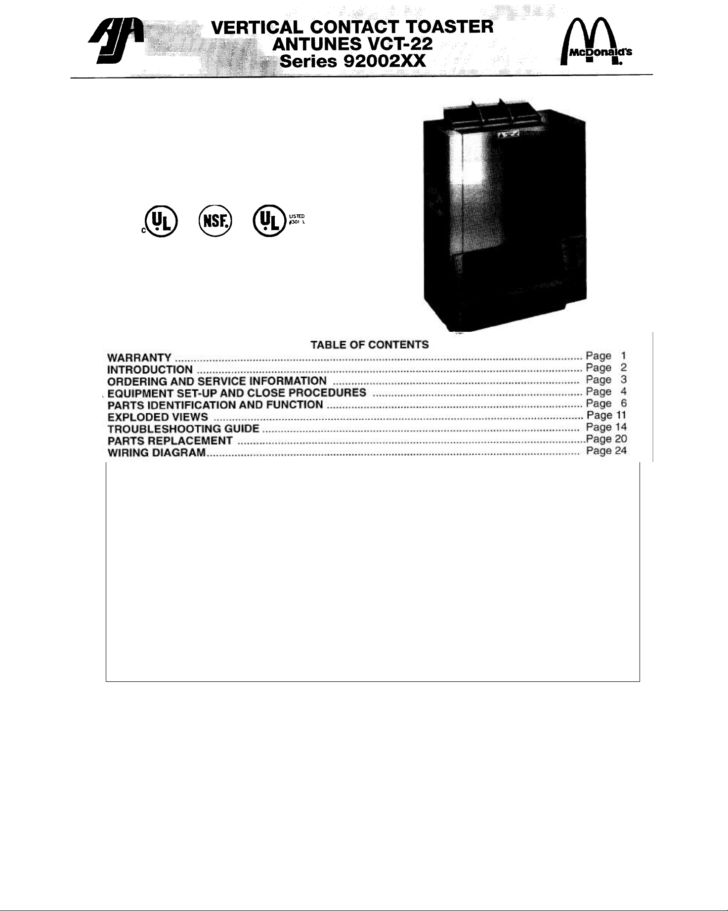
Page 1
Place this chapter in the Bun Toaster section
of your Equipment Manual.
MANUFACTURED
EXCLUSIVELY FOR
McDONALD'S® BY
A.J. ANTUNES & CO. 1025 NATIONAL
AVE. ADDISON, ILLINOIS 60101,
U.S.A. PHONE: 1 (630)543-8650 TOLL
FREE: 1-800-253-2991
FAX: 1 (630) 543-0359
THIS OWNER'S MANUAL IS FOR THE FOLLOWING
MANUFACTURING NUMBERS: 9200265,9200266, 9200272
& 9200273
Equipment manufactured by Roundup Food Equipment Division of A. J. Antunes & Co. has been constructed of the finest materials available and
manufactured to high quality standards. These units are warranted to be free from mechanical and electrical defects for a period of one year from
date of purchase under normal use and service, and when installed in accordance with manufacturer's recommendations. To insure continued
proper operation of the units, follow the maintenance procedure outlined in the Owner's Manual.
1. This warranty does not cover cost of installation, defects caused by improper storage or handling prior to placing of the Equipment. This warranty
does not include overtime charges or work done by unauthorized service agencies or personnel. This warranty does not cover normal
maintenance, calibration, or regular adjustments as specified in operating instructions, or manuals (see Owner's Manual of specific product): and/or
labor involved in moving adjacent objects to gain access to the Equipment. This warranty does not cover consumable items such as grill covers,
gaskets, O-rings and bulbs. This warranty does not pay travel, mileage, or any other charges for a service to reach the equipment's location (unless
stated in the Owner's Manual).
2. Roundup reserves the right to make changes in design or add any improvements on any product. The right is always reserved to modify equipment
because of factors beyond our control and government regulations. Charges to update equipment do not constitute a warranty charge.
3. If shipment is damaged in transit the purchaser should make his claim directly upon the carrier. Careful inspection should be made of the
shipment as soon as it arrives and visible damage should be noted upon the carrier's receipt. Damage should be reported to the carrier. This
damage is not covered under this warranty.
4. Warranty charges do not include freight or foreign, excise, municipal or other sales or use taxes. All such freight and taxes are the responsibility of
the purchaser.
5. THIS WARRANTY IS EXCLUSIVE AND IS IN LIEU OF ALL OTHER WARRANTIES, EXPRESSED OR IMPLIED, INCLUDING ANY IMPLIED
WARRANTY OR MERCHANTABILITY OR FITNESS FOR A PARTICULAR PURPOSE, EACH OF WHICH IS HEREBY EXPRESSLY
DISCLAIMED. THE REMEDIES DESCRIBED ABOVE ARE EXCLUSIVE AND IN NO EVENT SHALL ROUNDUP BE LIABLE FOR SPECIAL
CONSEQUENTIAL OR INCIDENTAL DAMAGES FOR THE BREACH OR DELAY IN PERFORMANCE OF THIS WARRANTY.
1010691 5/97
This manual is for the exclusive use of licensees and employees of McDonald's Systems, Inc.
© 1997 McDonald's Corporation Printed in
All Rights Reserved The United States of America
Page 2
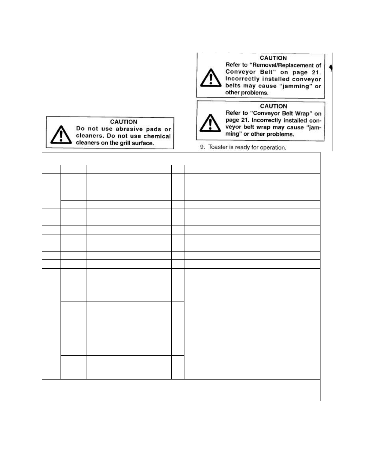
INTRODUCTION
The Antunes Vertical Contact Toaster, Model VCT-22
is designed for contact toasting of buns. The toaster is
designed to allow the operator to place the buns on
both sides of the heated platen at the same time. Buns
are placed into the bun feeder on the top of the
toaster. Uniform golden-brown, warm buns are
retrieved at the base of the toaster.
Hazard Communication Standard (HCS) — The
procedures in this chapter include the use of
chemical products. These chemical products will
be highlighted with bold face letters followed by
the abbreviation (HCS). See Hazard
Communication Standard (HCS) Manual for the
appropriate Material Safety Data Sheet(s) (MSDS).
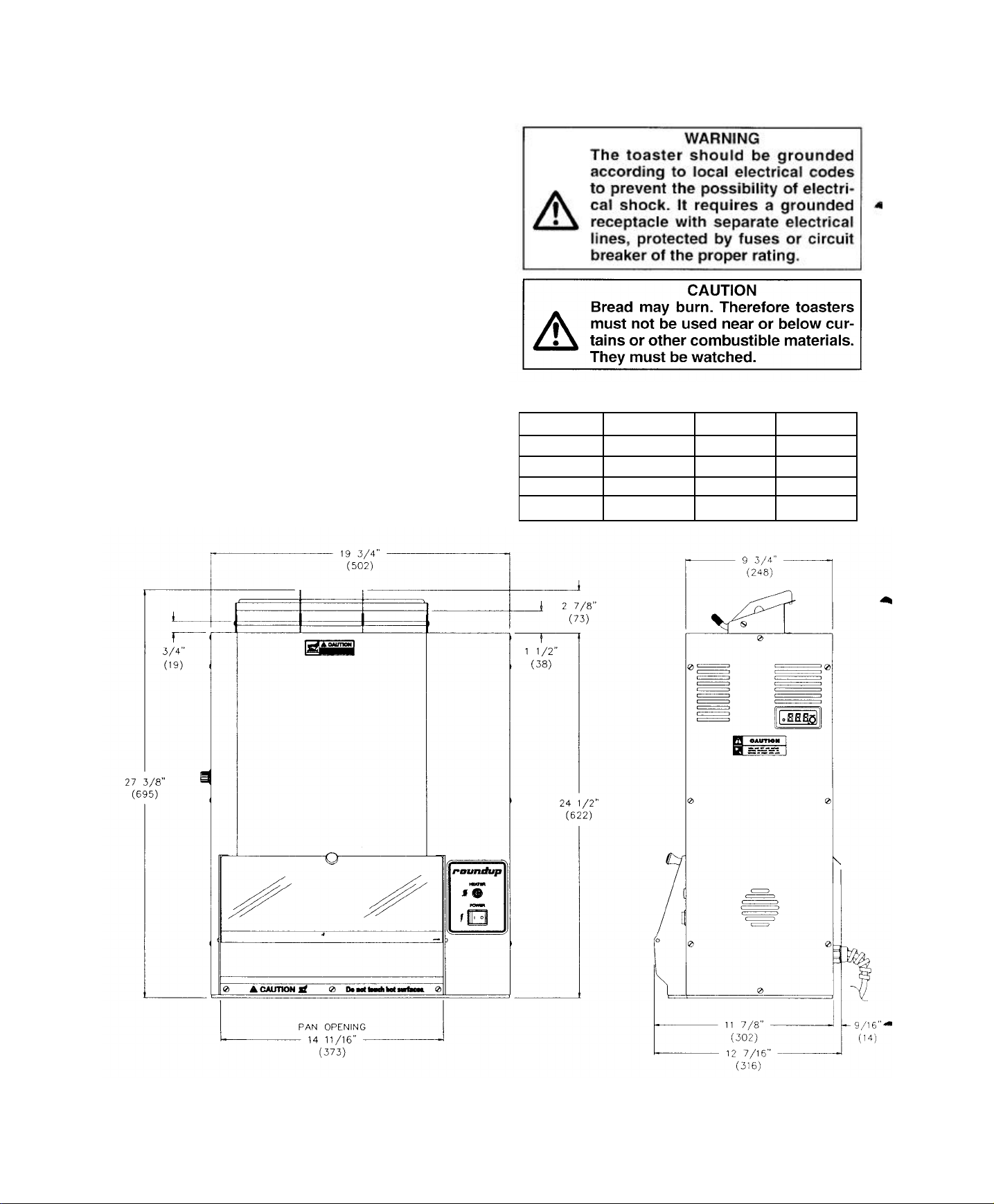
DIMENSIONS
19 1/2 inches (495 mm) wide 12 7/16
inches (316 mm) deep 27 3/8 inches
(695 mm) high
ELECTRICAL RATINGS:
VOLTAGE WATTS AMPS HERTZ
208 2750 13.22 50/60
220 3077 13.99 50/60
230 3363 14.62 50/60
240 3662 15.26 50/60
Page 3
ORDERING/SERVICE INFORMATION
Use only genuine Antunes replacement parts in this
unit. Use of replacement parts other than those
supplied by the manufacturer voids the warranty and
U.L. status.
Your Authorized Service Agency has a parts price list
and inform you of the cost of parts.
Parts Location - To find items you want to order from
the Parts List, proceed as follows:
1. Look at the parts drawing to locate the correct
part needed.
2. Use the item number from the parts drawing to
locate the correct parts in the Parts List. This
section will have the Antunes part number and a
description of the part.
Ordering Information - After finding the parts you want
to order on the Parts List, write down the following
information.
Commonly replaced items are stocked by your
Authorized Service Agency and will be sent out when
your order is received. Other parts will be ordered by
your Authorized Service Agency from A.J. Antunes &
Co.
If technical help is needed, contact the factory service
department. Please have the following information
ready when you call our factory service department:
*Fill in for your records. AUTHORIZED
RETURN POLICY:
No product may be returned without Antunes' prior
written approval. Transportation charges are to be
prepaid by Buyer. Returned goods are subject to
Antunes' inspection and acceptance. Antunes may, at
its discretion, replace any or all returned items within a
reasonable time after Antunes determines that the
returned goods are not in accordance herewith; and in
such event Antunes shall not be liable for any
damages arising from the defective delivery or delay
caused thereby. When expressly authorized by
Antunes in writing, unused products may be returned
to Antunes, subject to service handling, restocking and
rebuilding charges to "as new" condition.
Page 4
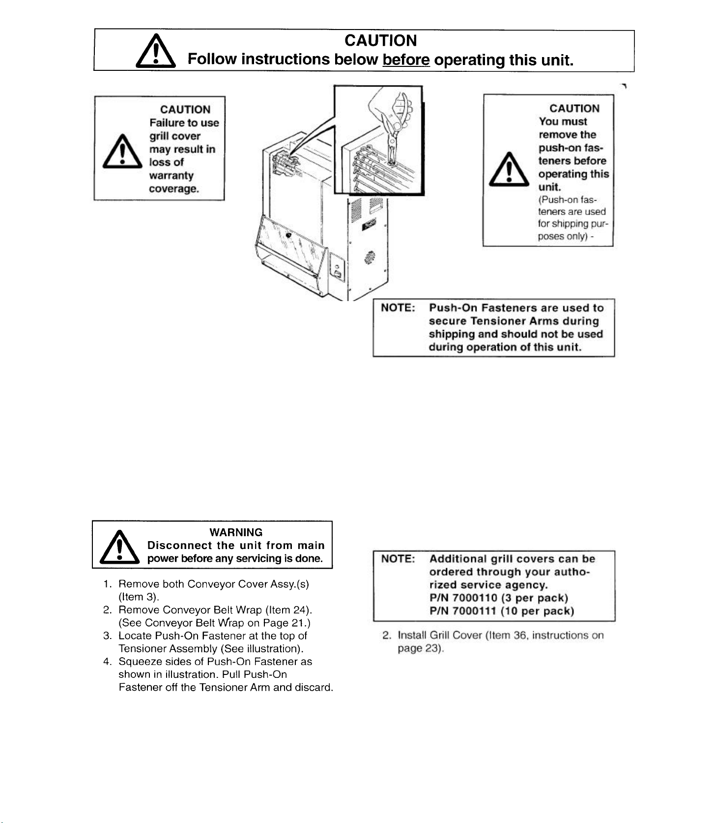
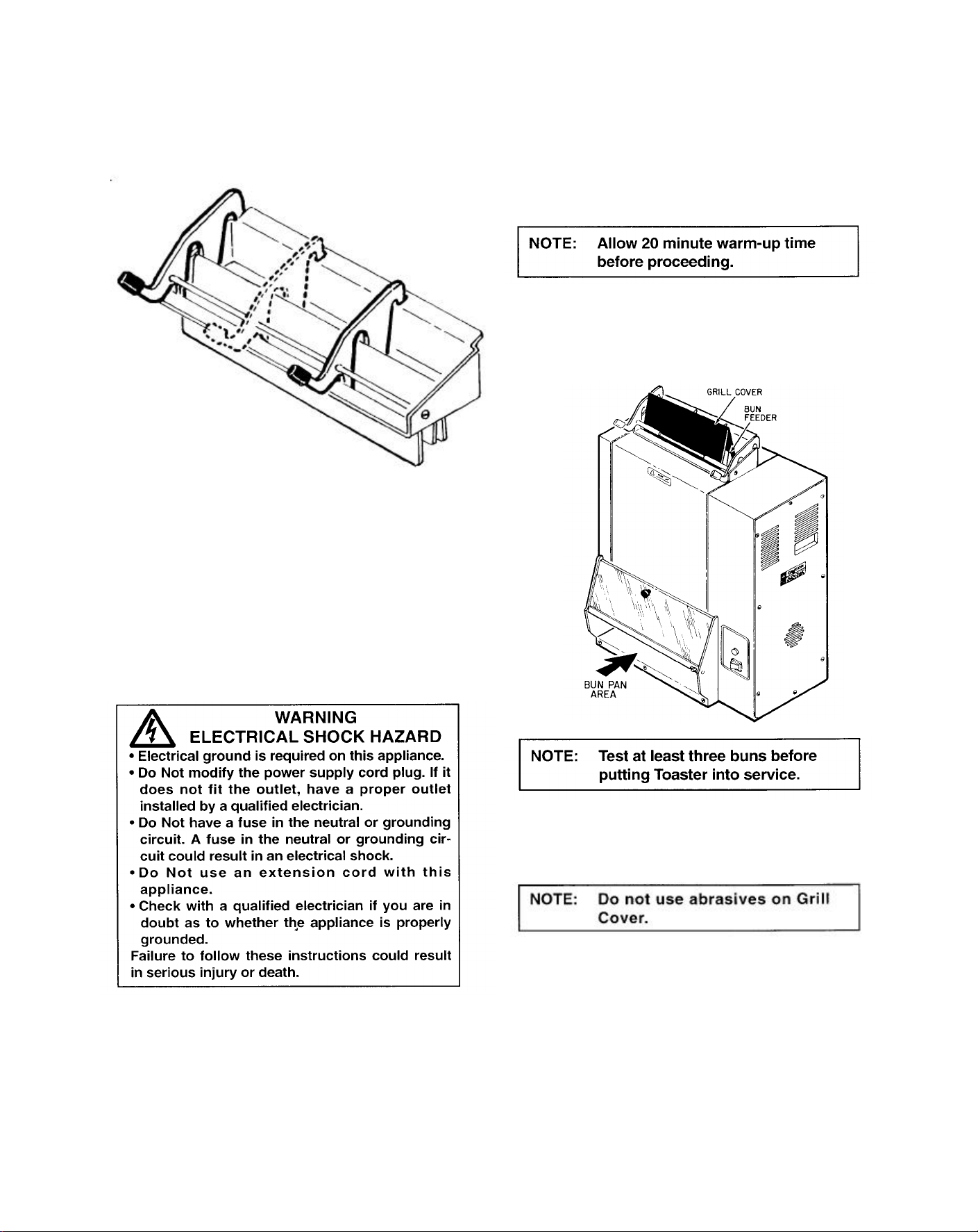
REMOVE PUSH-ON FASTENERS FROM
INSTALLATION
THE TENSIONERS ON MODEL VCT-22
• This procedure removes the Push-On Fasteners
from the Tensioners on your VCT-22. The PushOn Fasteners are needed for shipping only and
are not required for operation.
• This Toaster has four (4) Tensioner Assemblies,
two (2) on each side. Each Tensioner Assembly
has four (4) Push-On Fasteners, two at the top
and two at the bottom. This is a total of sixteen
(16) Push-On Fasteners. We recommend
removing ALL the Push-On Fasteners during
this procedure.
5. Locate and remove the remaining Push-On
Fasteners.
6. Install Conveyor Belt Wrap.
7. Reattach the Conveyor Cover Assy.(s).
8. Test operation of Toaster before returning to
service.
The toaster is shipped completely wired and ready
to connect to a grounded power supply.
To set up the toaster for operation: 1.
Install Bun Feeder (Item 26).
Page 5
3. Adjust Divider Weldment(s) on Bun Feeder to fit
buns being toasted.
Set bun adjustment knobs found on left side (Item
30) of unit: Back should be set to 11/16", (#5) for
bun crowns (top) and the front should be set to
1/2", (#2) for bun heels (bottom).
OPERATION
1. Connect Unit to power supply.
2. Turn bun adjustment knobs (Item 30) to
desired setting.
3. Move Rocker Switch (Item 20) to "ON"
position.
4. Drop buns into Toaster. Cut sides of heel
and crown must face each other (heel in
front, crown in back).
5. Toasted heel and crown will drop into the Bun
Pan (Not included).
5. Connect Toaster to power supply (See
Specification Plate for proper voltage).
6. Unit is now ready for operation.
DAILY MAINTENANCE
When the toaster is cool, remove the Grill Cover
and Bun Feeder. Clean with soap and water and
allow to air dry.
Re-install all parts after drying.
MONTHLY MAINTENANCE
1. Move Rocker Switch (Item 20) to "OFF"
position and unplug power cord.
2. Perform daily maintenance.
3. Remove Conveyor Belt Wrap. (See "Conveyor
Belt Wrap", Page 21).
Page 6
8. Reverse above procedures to assemble the
4. Remove Conveyor Belts (See "Conveyor Belt",
Page 21).
5. Remove both Tensioner assemblies (Item 4) by
pressing down lightly on the rods until they are
free from the Rod Brackets (Item 27). Lift both
tensioners up and out of the unit.
6. Clean Belts and Tensioners with soap and water,
and allow to air dry.
7. Clean the grill surface with a clean, damp cloth
and allow to air dry.
PARTS IDENTIFICATION AND FUNCTION
ITEM PART NO. DESCRIPTION QTY FUNCTION
toaster.
1 0010190 CONVEYOR BELT 2 FLEXIBLE ASSEMBLY USED TO MOVE BUNS THROUGH THE
0800204 1/2" PITCH LINK (SMALL) 3 SMALLER COMPONENT OF CONVEYOR BELT.
0800121 3/4" PITCH LINK (LARGE) 38 LARGER COMPONENT OF CONVEYOR BELT.
2 2150117 IDLER SHAFT 2 SERVES AS UPPER AXLE FOR CONVEYOR BELT.
3 0011189 CONVEYOR COVER ASSY 2 SHEET METAL PART COVERING MOVING PARTS.
4 0011135 TENSIONER ASSY 4 GUIDES CONVEYOR BELT.
5 0800332 ROD, CONVEYOR COVER 2 BOTTOM SUPPORT FOR CONVEYOR COVER ASSY.
6 215K111 SPROCKET 8 USED TO MOVE CONVEYOR BELT.
7 212K103 SPACER KIT 1 METAL RING USED TO CORRECTLY POSITION DRIVE SHAFT.
8 0021107 CONTROL COVER WELDMENT 1 SHEET METAL PART COVERING ELECTRICAL PARTS.
9 2150118 DRIVE SHAFT 2 SERVES AS LOWER AXLE FOR CONVEYOR BELT.
10 0700535 POWER CORD/PLUG ASSY
20A/#320P6W PIN AND SLEEVE PLUG,
(VCT-22 CD, #9200261)
0700552 POWER CORD/PLUG ASSY 20A, L6-20P
TWIST-LOCK PLUG -STRAIGHT (VCT22CS, #9200263)
0700437 POWER-CORD/PLUG ASSY 16A/ICE309
#316P6W PIN AND SLEEVE PLUG, (VCT
22 HI, #9200270)
TOASTER.
1 TRANSFERS ELECTRIC POWER TO THE UNIT.
1
1
0700453 HARMONIZED POWER CORD WITH 16A,
CEE 7/7 SCHUKO PLUG (VCT 22 HC,
#9200271)
6
1
Page 7
ITEM PART NO. DESCRIPTION QTY FUNCTION
11 0011131 TEMPERATURE CONTROL 1 MAINTAINS AND CONTROLS HEAT TO GRILL.
ASSY.
11A 407K025 TEMPERATURE CONTROL 1
DISPLAY
11B 407K024 CONTROL BOARD, 1
TRANSFORMER/RELAY
12 2150158 BALL BEARING 2 ALLOWS SMOOTH ROTATION OF DRIVE SHAFTS.
13 050K115 BEARING RETAINER KIT 1 POSITIONS AND HOLDS BALL BEARING.
14 2150109 DRIVE SPROCKET-16 TOOTH 1 TOOTHED METAL PART THAT TRANSFERS POWER TO
DRIVE SHAFTS FROM DRIVE CHAIN.
15 2150178 DRIVE CHAIN (VCT -22) 1 USED TO TRANSFER POWER FROM MOTOR SPROCKET
TO DRIVE SPROCKET.
16 0011193 IDLER SPROCKET ASSY 1 REVERSES DRIVE CHAIN MOTION.
17 0500538 MOTOR MOUNTING BRKT. 1 METAL SUPPORT USED TO SECURE MOTOR BRACKET
TO TOASTER.
18 400K153 DRIVE MOTOR KIT 1 ELECTRICAL PART USED TO MOVE DRIVE CHAIN.
19 2150110 MOTOR SPROCKET (25B20/60HZ) 1 USED TO MOVE DRIVE CHAIN.
2150177 MOTOR SPROCKET (25B24/50HZ) 1
20 4010137 SWITCH, ROCKER (250 VAC) 1 CONTROLS ELECTRICAL POWER TO THE UNIT.
LIGHTS UP WHEN POWER IS ON.
21 4060304 TERMINAL BLOCK 1 PROVIDES CONNECTION POINT FOR ELECTRICAL WIRES.
22 0503156 TEMPERATURE CONTROL 1 METAL SUPPORT USED TO SECURE COMPONENTS OF
BRACKET TEMPERATURE CONTROL ASSEMBLY.
23 4060229 INDICATOR LIGHT (230 VAC) 1 COMES ON WHEN HEATING ELEMENT IS HEATING,
CONTROLLED BY THE THERMOSTAT.
24 0400304 CONVEYOR BELT WRAP 2 SILICONE COVER THAT PREVENTS DAMAGE TO BUNS
AND HOLDS TO HEAT THE BUNS.
25 0011191 ROLLER TENSIONER ASSY 2 METAL PART THAT KEEPS CONVEYOR BELT AT PROPER
TENSION.
26 7000116 BUN FEEDER 1 SHEET METAL PART THAT HOLDS BUNS AND GUIDES
THEM INTO THE TOASTER.
27 050K114 ROD BRACKET KIT 2 METAL PART THAT HOLDS TENSIONER AND ALLOWS IT
TO MOVE DURING ADJUSTMENT.
28 1000982 CONTROL PANEL LABEL 1 IDEN TIFIES CONTROLS.
29 100P983 DIAL LABEL (PKG. OF 10) 1 IDENTIFIES BUN THICKNESS SETTINGS.
30 2100123 KNOB (W / SETSCREWS) 2 MOVES CONVEYOR CAM TO PROVIDE THICKNESS
ADJUSTMENT.
31 0503195 COVER. END HOUSING 1 SHEET METAL PART THAT COVERS MECHANICAL
COMPONENTS.
32 4050212 THERMOCOUPLE ASSY. 1 SENSES TEMPERATURE.
33 215K158 BEARING RETAINER KIT 6 POSITIONS AND HOLDS BALL BEARING.
34 0021103 END HOUSING WELDMENT 1 PROTECTIVE METAL SIDE, SUPPORTS INTERNAL PARTS.
7
Page 8
ITEM 35 PART NO.
0500543
36 7000110 GRILL COVER (PKG. OF 3) TEFLON PART THAT COVERS GRILL, CREATES
7000111 GRILL COVER (PKG. OF 10) - SMOOTH TOASTING SURFACE.
37 38 0100213
0021102
DESCRIPTION SEPARATOR CONE QTY 1 FUNCTION METAL PART THAT GUIDES BUN ONTO GRILL.
GRILL (208 VOLT) CONTROL HOUSING 1 1 HEATED ALUMINUM CASTING. PROTECTIVE METAL SIDE,
SUPPORTS INTERNAL COMPONENTS.
39 7000121 SLIDE RAIL KIT (INCLUDES 2 SLIDE
40 41 0021116
0021111
42 0021114 DIVIDER WELDMENT (LH) 1 MOVABLE PART THAT ADJUSTS FROM SIDE TO SIDE AND GUIDES
43 2000200 TUBE 1 SUPPORTS DIVIDER WELDMENTS.
44 0021113 DIVIDER WELDMENT (RH) 1 MOVABLE PART THAT ADJUSTS FROM SIDE TO SIDE AND GUIDES
45 7000119 THERMOCOUPLE RETAINER KIT 1 HOLDS THERMOCOUPLE IN PLACE.
46 0503200 PANEL, REAR 1 SHEET METAL PART - COVERS BACK OF BUN PAN AREA.
47 4030162 HIGH LIMIT THERMOSTAT 1 RESETTABLE SAFETY SWITCH WHICH TURNS THE POWER OFF
48 0400258 STRAIN RELIEF 1 HOLDS POWER CORD SET TO CABINET.
49 0503212 STOP, PAN 1 POSITIONS REAR OF BUN PAN.
50 0503210 LOCATOR, BUN PAN 2 POSITIONS AND HOLDS BUN PAN.
" 0011196 FLOOR ASSEMBLY 1 SHEET METAL PART - CREATES SPACE FOR BUN PAN.
52 53 0503131
0503135
RAILS FOR TENSIONERS)
CONVEYOR CAM BUN FEEDER
WELDMENT
PLATEN EXTENSION O UTER PLATEN
EXTENSION INNER
2 PREVENTS METAL-TO-METAL CONTACT AND LIMITS NOISE.
2 1 POSITIONS CONVEYOR BELT TO TOAST DIFFERENT THICKNESS
OF BUN. SHEET METAL PART THAT HOLDS COMPONENTS OF
BUN FEEDER.
BUNS INTO TOASTER.
BUNS INTO TOASTER.
TO THE STEAM GENERATOR WHEN THE THERMOSTAT IS NOT
CONTROLLING MAXIMUM TEMP.
1 1 OUTSIDE HALF OF COMPONENT THAT GUIDES BUNS TO BUN
PAN. INSIDE HALF OF COMPONENT THAT GUIDES BUNS TO BUN
PAN.
54 4030319 HEATER, SILICONE 1 PART IS GLUED TO BOTTOM OF FLOOR ASSEMBLY, PROVIDES
55 0503192 BASE 1 SHEET METAL PART - COVERS BOTTOM OF UNIT.
56 . ......
0503155
*57 0700553 WIRE SET 1 PERMITS CONNECTION OF ALL ELECTRICAL PARTS.
58 0200208 GASKET, BASE 1 SEALS UNIT TO COUNTER.
59 0011187 DOOR ASSY. 1 CLEAR PLASTIC - ALLOWS VIEWING OF AND ACCESS TO BUN
60 0503198 BUN CHUTE 1 GUIDES BUNS INTO BUN PAN AFTER TOASTING.
MOTOR BRACKET - METAL SUPPORT USED TO SECURE DRIVE MOTOR TO MOTOR
HEAT IN BUN PAN AREA.
MOUNTING. BRACKET.
PAN.
8
Page 9

ITEM PART NO. DESCRIPTION QTY FUNCTION
35 0500543 SEPARATOR CONE 1 METAL PART THAT GUIDES BUN ONTO GRILL.
36 7000110 GRILL COVER (PKG. OF 3) - TEFLON PART THAT COVERS GRILL, CREATES
7000111 GRILL COVER (PKG. OF 10) - SMOOTH TOASTING SURFACE.
37 0100213 GRILL (208 VOLT) 1 HEATED ALUMINUM CASTING.
38 0021102 CONTROL HOUSING 1 PROTECTIVE METAL SIDE, SUPPORTS INTERNAL COMPONENTS.
39 7000121 SLIDE RAIL KIT (INCLUDES 2 SLIDE
40 41 0021116
0021111
42 0021114 DIVIDER WELDMENT (LH) 1 MOVABLE PART THAT ADJUSTS FROM SIDE TO SIDE AND
43 2000200 TUBE 1 SUPPORTS DIVIDER WELDMENTS.
44 0021113 DIVIDER WELDMENT (RH) 1 MOVABLE PART THAT ADJUSTS FROM SIDE TO SIDE AND
45 7000119 THERMOCOUPLE RETAINER KIT 1 HOLDS THERMOCOUPLE IN PLACE.
46 0503200 PANEL, REAR 1 SHEET METAL PART - COVERS BACK OF BUN PAN AREA.
47 4030162 HIGH LIMIT THERMOSTAT 1 RESETTABLE SAFETY SWITCH WHICH TURNS THE POWER OFF
48 0400258 STRAIN RELIEF 1 HOLDS POWER CORD SET TO CABINET.
49 0503212 STOP, PAN 1 POSITIONS REAR OF BUN PAN.
50 0503210 LOCATOR, BUN PAN 2 POSITIONS AND HOLDS BUN PAN.
51 0011196 FLOOR ASSEMBLY 1 SHEET METAL PART - CREATES SPACE FOR BUN PAN.
52 0503131 PLATEN EXTENSION OUTER 1 -] OUTSIDE HALF OF COMPONENT THAT GUIDES BUNS TO BUN
RAILS FOR TENSIONERS)
CONVEYOR CAM BUN FEEDER
WELDMENT
2 PREVENTS METAL-TO-METAL CONTACT AND LIMITS NOISE.
2 1 POSITIONS CONVEYOR BELT TO TOAST DIFFERENT THICKNESS
OF BUN. SHEET METAL PART THAT HOLDS COMPONENTS OF
BUN FEEDER.
GUIDES BUNS INTO TOASTER.
GUIDES BUNS INTO TOASTER.
TO THE STEAM GENERATOR WHEN THE THERMOSTAT IS NOT
CONTROLLING MAXIMUM TEMP.
PAN.
53 0503135 PLATEN EXTENSION INNER 1 INSIDE HALF OF COMPONENT THAT GUIDES BUNS TO BUN PAN.
54 4030319 HEATER, SILICONE 1 PART IS GLUED TO BOTTOM OF FLOOR ASSEMBLY, PROVIDES
55 0503192 BASE 1 SHEET METAL PART - COVERS BOTTOM OF UNIT.
56 0503155 MOTOR BRACKET 1 METAL SUPPORT USED TO SECURE DRIVE MOTOR TO MOTOR
'57 0700553 . . - WIRE SET 1 PERMITS CONNECTION OF ALL ELECTRICAL PARTS.
58 59 60 0200208
0011187
0503198
NOT SHOWN
GASKET, BASE DOOR ASSY. BUN
CHUTE
HEAT IN BUN PAN AREA.
MOUNTING. BRACKET.
1 1 1 SEALS UNIT TO COUNTER. CLEAR PLASTIC - ALLOWS VIEWING
OF AND ACCESS TO BUN PAN. GUIDES BUNS INTO BUN PAN
AFTER TOASTING.
8
Page 10

PARTS IDENTIFICATION
10
Page 11

EXPLODED VIEW
Page 12

12
Page 13

EXPLODED VIEW
13
Page 14

TROUBLESHOOTING GUIDE
PROBLEM PROBABLE CAUSE CORRECTIVE ACTION
No heat and conveyor belts do
not move.
Not enough voltage, defective power cord,
Defective wiring. Check all electrical connections for bums,
No heat and conveyor belts
move.
Toaster is installed incorrectly. Perform Installation and Operating Procedures
defective power switch.
Defective wiring. Check all electrical connections for burns
on Page 4 of this manual.
Check receptacle for correct voltage. (See
Specifications, Page 2). With unit plugged in and
Rocker Switch ON, check for correct voltage into
Rocker Switch. If low or zero voltage, replace
Power Cord. If correct voltage, check for correct
voltage out of Rocker Switch. If low or no
voltage, replace Rocker Switch.
discoloration or arcing. Replace all connections
or components with damaged terminals.
Replace all damaged wiring with the same or a
higher rated wire.
discoloration or arcing. Replace all connections
or components with damaged terminals.
Replace all damaged wiring with t he same or a
higher rated wire.
Defective temperature display control or defective
grill.
High limit thermostat tripped or defective. With power off and unit cool to the touch,
To check temperature display control -Allow unit
to warm up for 20 minutes. A. Check grill
temperature at center of grill (with conveyor belt
wrap, conveyor belt, tensioners, and grill cover
removed)., B. After grill temperature reaches a
maximum of 469° -471°F (242°-244°C) and the
temperature begins to drop, the indicator light
(Item 23) should turn off. If test readings do not
agree with these figures, replace temperature
display control. To check grill -A. Use an Ohm
meter to test resistance of the grill heater
(Disconnect one wire to isolate heater). Correct
cold resistance is: 15.73 Ohms for 208V/2750
watt grills.
remove one wire and check across terminals for
continuity. If continuity, part is good. If no
continuity, press reset and retest. If still no
continuity, replace.
Page 15

PROBLEM PROBABLE CAUSE CORRECTIVE ACTION
Grill is hot and conveyor
belts do not move.
Toaster is installed incorrectly. Perform Installation and Operating
Procedures on Page 4 of this manual.
Defective wiring. Check all electrical connections for burns,
discoloration or arcing. Replace all
connections or components with damaged
terminals. Replace all damaged wiring with
the same or a higher rated wire.
Defective drive motor or wrong drive motor. To check drive motor -A. Measure
resistance of motor coil. Replace motor if
coil measures either open circuit or zero
resistance. B. Mark the drive motor
sprocket and count the turns per minute.
Correct drive motor speed is three (3) turns
per minute.
Defective drive chain or loose sprocket. Check drive chain for kinks, broken or bent
links or other damage. Check motor
sprocket and drive sprockets (on drive
shaft), tighten setscrew on flat of shaft if
needed. Also check for
broken/damaged/worn sprockets. Replace
as needed.
Conveyor Cover Assy.(s) not installed. Install Conveyor Cover Assy.(s).
Conveyor belts installed incorrectly. Install conveyor belt to match diagram on
Page 21. Be sure that the "hook" faces out
and the point of the hook is down.
Roller Tensioner Assy. or Tensioner bent or
missing.
Replace Roller Tensioner Assy.(s) (Item
25) or Tensioner (Item 4) if damaged or
missing.
Conveyor belt is loose or missing links (41
links required).
Remove conveyor belt by squeezing any
two links together to "unhook" the links. Lay
conveyor belt flat and count links. Correct
amount is forty one (41) links, 38 large and
3 small links. To shorten conveyor belt,
remove one or more small links. Replace
entire conveyor belt if links are damaged.
Product is over-toasted or
grill heat is too high or drop
time is too slow.
Defective wiring. Check all electrical connections for burns,
discoloration or arcing. Replace all
connections or components with damaged
terminals. Replace all damaged wiring with
the same or a higher rated wire.
Defective temperature display control or
defective grill.
To check temperature display control Allow unit to warm up for 20 minutes. A.
Check grill temperature at center of grill
(with conveyor belt wrap, conveyor belt,
tensioners, and grill cover removed),
15
Page 16

PROBLEM PROBABLE CAUSE CORRECTIVE ACTION
(Continued) Product is over-
toasted or grill heat is too high
or drop time is too slow.
Defective drive motor or wrong drive motor. To check drive motor -A. Measure resistance of
Defective drive chain or loose sprocket. Check drive chain for kinks, broken or bent links
Conveyor Cover Assy.(s) not installed. Install Conveyor Cover Assy.(s).
(Continued) Defective temperature display
control or defective grill.
B. After grill temperature reaches a maximum of
469°-471°F (242°-244°C) and the temperature
begins to drop, the indicator light (Item 23)
should turn off. If test readings do not agree with
these figures, replace temperature control
display. To check grill -A. Use an Ohm meter to
test resistance of the grill heater (Disconnect
one wire to isolate heater). Correct cold
resistance is: 15.73 Ohms for 208V/2750 watt
grills.
motor coil. Replace motor if coil measures either
open circuit or zero resistance. B. Mark the
drive motor sprocket and count the turns per
minute. Correct drive motor speed is three (3)
turns per minute.
or other damage. Check motor sprocket and
drive sprockets (on drive shaft), tighten
setscrew of flat of shaft if needed. Also check
for broken/damaged/worn sprockets. Replace
as needed.
Conveyor belts installed incorrectly. Install conveyor belt to match diagram on Page
Conveyor belt is loose or missing links (41 links
Roller Tensioner Assy. or Tensioner bent or
Bun adjustment knobs set incorrectly. Measure bun thickness and set bun adjustment
Product is under-toasted or grill
heat is too low or drop time is
too fast.
required).
missing.
Not enough voltage, defective power cord,
defective power switch.
21. Be sure that the "hook" faces out and the
point of the hook is down.
Remove conveyor belt by squeezing any two
links together to "unhook" the links. Lay
conveyor belt flat and count links. Correct
amount is forty one (41) links, 38 large and 3
small links. To shorten conveyor belt, remove
one or more small links. Replace entire
conveyor belt if links are damaged.
Replace Roller Tensioner Assy. (Item 25) or
Tensioner (Item 4) if damaged or missing.
knobs correctly.
Check receptacle for correct voltage. With unit
plugged in and Rocker Switch ON, check for
voltage at bottom of Rocker Switch. If low or
zero voltage, replace Power Cord. If correct
voltage, check at top of power switch for correct
voltage. If low or no voltage, replace Rocker
Switch.
16
Page 17

PROBLEM PROBABLE CAUSE CORRECTIVE ACTION
Product is getting "Stuck" or
(Continued) Product is
under-toasted or grill heat is
too low or drop time is too
fast.
Defective wiring. Check all electrical connections for bums,
discoloration or arcing. Replace all
connections or components with damaged
terminals. Replace all damaged wiring with
the same or a higher rated wire.
Defective temperature display control or
defective grill.
To check temperature display control -Allow
unit to warm up for 20 minutes. A. Check
grill temperature at center of grill (with
conveyor belt wrap, conveyor belt,
tensioners, and grill cover removed)., B.
After grill temperature reaches a maximum
of 469°-471°F (242°-244°C) and the
temperature begins to drop, the indicator
light (Item 23) should turn off. If test
readings do not agree with these figures,
replace temperature display control. To
check grill -A. Use an Ohm meter to test
resistance of the grill heater (Disconnect one
wire to isolate heater). Correct cold
resistance is: 15.73 Ohms for 208V/2750
watt grills.
Defective drive motor or wrong drive motor. To check drive motor -A. Measure
resistance of motor coil. Replace motor if
coil measures either open circuit or zero
resistance. B. Mark the drive motor sprocket
and count the turns per minute. Correct
drive motor speed is three (3) turns per
minute.
Bun adjustment knobs set incorrectly. Measure bun thickness and set bun
adjustment knobs correctly.
conveyor belts "Stop" when
product is toasting.
Not enough voltage, defective power cord,
defective power switch.
Check receptacle for correct voltage. With
unit plugged in and Rocker Switch ON,
check for voltage at bottom of Rocker
Switch. If low or zero voltage, replace Power
Cord. If correct voltage, check at top of
power switch for correct voltage. If low or no
voltage, replace Rocker Switch.
Defective wiring. Check all electrical connections for burns,
discoloration or arcing. Replace all
connections or components with damaged
terminals. Replace all damaged wiring with
the same or a higher rated wire.
17
Page 18

PROBLEM PROBABLE CAUSE CORRECTIVE ACTION
(Continued) Product is getting
"Stuck" or conveyor belts
"Stop" when product is
toasting.
Defective drive chain or loose sprocket. Check drive chain for kinks, broken or bent links
Conveyor Cover Assy.(s) not installed. Install Conveyor Cov er Assy.(s).
Conveyor belts installed incorrectly. Install conveyor belt to match diagram on Page
Conveyor belt is loose or missing links (41 links
Defective drive motor or wrong drive motor. To check drive motor -A. Measure resistance of
required).
motor coil. Replace motor if coil measures either
open circuit or zero resistance. B. Mark the
drive motor sprocket and count the turns per
minute. Correct drive motor speed is three (3)
turns per minute.
or other damage. Check motor sprocket and
drive sprockets (on drive shaft), tighten
setscrew on flat of shaft if needed. Also check
for broken/damaged/worn sprockets. Replace
as needed.
21. Besure that the "hook" faces out and the
point of the hook is down.
Remove conveyor belt by squeezing any two
links together to "unhook" the links. Lay
conveyor belt flat and count links. Correct
amount is forty one (41) links, 38 large and 3
small links. To shorten conveyor belt, remove
one or more small links. Replace entire
conveyor belt if links are damaged.
Roller Tensioner Assy.(s) or Tensioner bent or
Bun adjustment knobs set incorrectly. Measure bun thickness and set bun adjustment
Conveyor belt wrap missing or not installed
Conveyor belts are "Jumping"
or "Snapping"
Defective drive motor or wrong drive motor. To check drive motor -A. Measure resistance of
missing.
properly.
Toaster is installed incorrectly. Perform Installation and Operating Procedures
Replace Roller Tensioner Assy. (Item 25) or
Tensioner (Item 4) if damaged or missing.
knobs correctly.
Install Conveyor Belt Wrap (Item 24) properly
(See ''Conveyor Belt Wrap" on Page 21).
on Page 4 of this manual.
motor coil. Replace motor if coil measures either
open circuit or zero resistance. B. Mark the
drive motor sprocket a nd count the turns per
minute. Correct drive motor speed is three (3)
turns per minute.
18
Page 19

PROBLEM PROBABLE CAUSE CORRECTIVE ACTION
(Continued) Conveyor belts are
"Jumping" or "Snapping"
Conveyor Cover Assy.(s) not installed. Install Conveyor Cover Assy.(s).
Conveyor belts installed incorrectly. Install conveyor belt to match diagram on Page
Conveyor belt is loose or missing links (41 links
Roller Tensioner Assy.(s) or Tensioner bent or
Bun adjustment knobs set incorrectly. Measure bun thickness and set bun adjustment
Defective drive chain or loose sprocket. Check drive chain for kinks, broken or bent
required).
missing.
links or other damage. Check motor sprocket
and drive sprockets (on drive shaft), tighten
setscrew of flat of shaft if needed. Also check
for broken/damaged/worn sprockets. Replace
as needed.
21. Be sure that the "hook" faces out and the
point of the hook is down.
Remove conveyor belt by squeezing any two
links together to "unhook" the links. Lay
conveyor belt flat and count links. Correct
amount is forty one (41) links, 38 large and 3
small links. To shorten conveyor belt, remove
one or more small links. Replace entire
conveyor belt if links are damaged.
Replace Roller Tensioner Assy. (Item 25) on
inside of face panel) or Tensioner (Item 4) if
damaged or missing.
knobs correctly.
19
Page 20

TEMPERATURE DISPLAY CONTROL/ CONTROL
BOARD TRANSFORMER/RELAY Removal -
1 Remove Control Cover Weldment (Item 8).
2. Remove screws holding Temperature Control
Assy. (Item 11).
3. Remove screw(s) holding the part.
4. Disconnect wires from part. Installation-
1. Connect wires to part.
2. Attach part to Temperature Control Assy.
3. Attach Temperature Control Assy. to Toaster.
4. Test operation before putting unit into service.
5. Installation is complete.
TEMPERATURE ADJUSTMENT
Setting Temperature Adjustment.
1. Turn Power Switch to ON.
2. Push and hold the Display Selector Button and
turn the Set Point Adjustment Knob to the
desired set point. Temperature range is 469°471°F (242°-244°C). Clockwise increases
temperature, counter-clockwise decreases
temperature.
20
Page 21

DRIVE MOTOR
With Power OFF -1. Remove Cover Panel
(Item 8).
^ 2. Remove Drive Motor/Motor Bracket r (Item
18/56).
3. Remove Motor Sprocket (Item 19) with a hex
wrench.
4. Attach Motor Bracket and Sprocket to new Mot or.
2. Move Bun Adjustment Knob to 3/4" (#6) to loosen
Conveyor belt and Conveyor Belt Wrap.
3. Move the Conveyor Belt Wrap until the "flap"
clan be lifted.
4. Lift the flap and remove the pin holding the
Conveyor Belt Wrap by pulling gently. Turn or
spin the pin to make removal easier.
Page 22

3. Disconnect Conveyor Belt by unhooking
both ends of one link, then remove
Conveyor Belt. Replacement -
1. Move Bun Adjustment Knobs to "3/4"(#6) to
loosen conveyor belt.
ROLLER TENSIONER ASSY.
With Power OFF -
1. Remove Conveyor Cover Assy. (Item 3).
2. Remove 8x32 nuts (Item S) from Roller
Tensioner Assy.
3. Remove old Roller Tensioner Assy.
4. Reverse steps 1-3 to complete procedure.
Page 23

INSTALLATION OF GRILL COVER
1 . Turn OFF the power and allow the unit to USE METAL TOOLS TO CREASE THE
cool completely. GRILL COVER!
" 2. Remove Grill Cover (Item 36), if one is in 5. Install Bun Feeder.
place. Remove the Bun Feeder (Item 26) 6. install the Grill Cover by draping it over
and set aside, both sides of the grill surface. Note that
3. Lay a Grill Cover on a clean, flat surface, the crease should be centered directly on
Note that the Grill Cover is longer than it the (black separator cone).
is wide. Fold exactly in half the LONG 7. check Grill Cover to be sure it is not
way caught in conveyor. Unit is now ready for
4. Crease the Grill Cover at the fold by use.
pressing the fold with a finger. DO NOT
Page 24

 Loading...