

Page 1

ASSEMBLY INSTRUCTIONS
Utility Bench II
Product Part#
36"w Utility Bench UTB3635zz-xx5
48"w Utility Bench UTB4835zz-xx5
60"w Utility Bench UTB6035zz-xx5
72"w Utility Bench UTB7235zz-xx5
NOTE: The Utility Bench Base Shelf shown above is not included.
Anthro Corporation® | 10450 SW Manhasset Dr. | Tualatin, OR 97062
Toll-free: 800.325.3841 | Fax: 800.325.0045 | email: sales@anthro.com | anthro.com
Outside the U.S. | Tel: 503.691.2556 | Fax: 503.691.2409
November 2013
Page 2
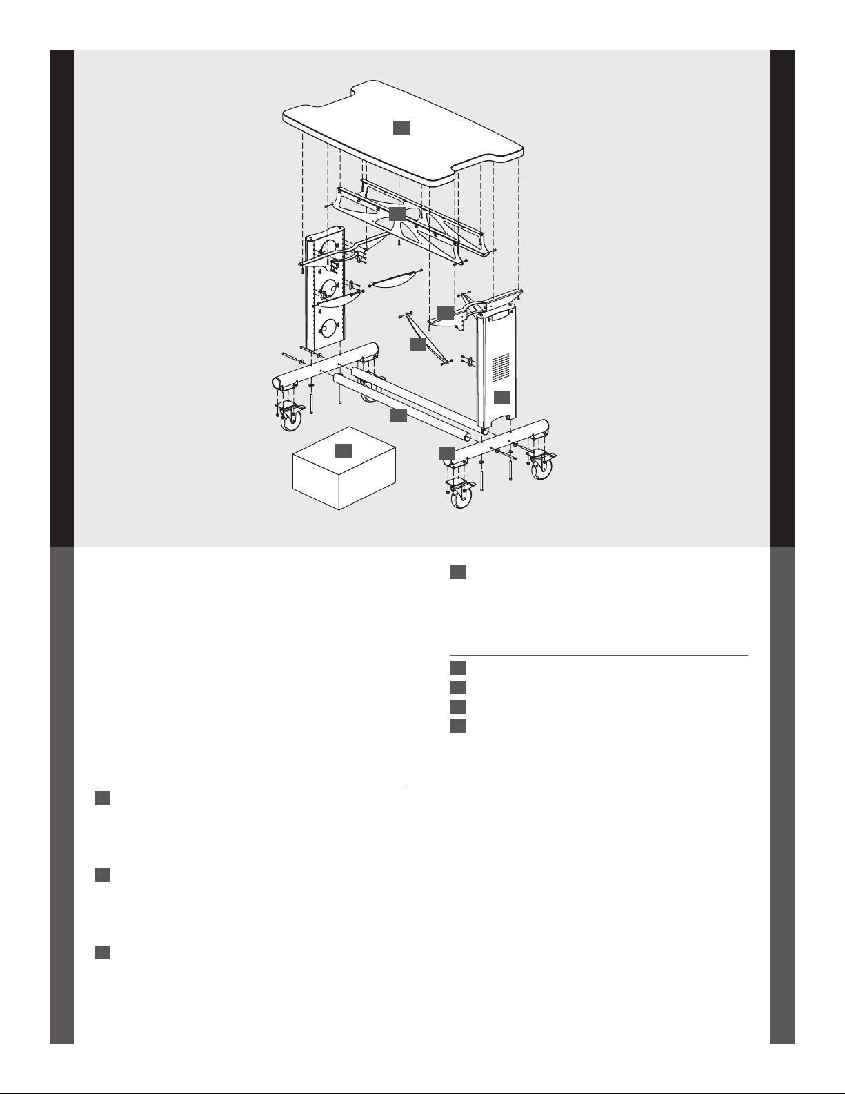
03
01
05
04
07
02
WELCOME
Thank you for purchasing the Utility Bench II!
If you have any questions or if we can help you
in any way, please contact us at 800.325.3841.
PARTS LIST
Before beginning assembly of your Utility Bench,
please take a moment to review the parts list
below to verify that your shipment is complete.
Product Quantity Part Numberxxx
01 Shelf
36"w Utility Bench 1 101-1134-00-00
48"w Utility Bench 1 101-1129-00-00
60"w Utility Bench 1 101-1128-00-00
72"w Utility Bench 1 101-1132-00-00
02 Cross Tube
36"w Utility Bench 2 125-5277-xx
48"w Utility Bench 2 125-5184-xx
60"w Utility Bench 2 125-5185-xx
72"w Utility Bench 2 125-5186-xx
03 Pan
36"w Utility Bench 2 225-2690-xx
48"w Utility Bench 2 225-5370-xx
60"w Utility Bench 2 225-5371-xx
72"w Utility Bench 2 225-5372-xx
2
08
06
04 Buttress
36"w Utiliity Bench 4 225-5386-xx
48"w Utility Bench 4 225-5386-xx
60"w Utility Bench 4 225-5387-xx
72"w Utility Bench 4 225-5388-xx
Product Quantity Part Number
05 Utility Bench Arm 2 225-2073-xx
06 Base Tube with Caster Plate 2 500-1002-xx
07 Leg Subassembly 2 835-5008-xx
08 Kit
5” Total Lock Caster-plate Mount 4 150-5081-00
End Cap 4 175-5158-xx
Cross End Bracket 4 225-5334-xx
Curved Washer 8 225-2050-xx
1/2" Button Head Screw 12 325-5003-00
Self-threading Screw 24 325-5010-00
Keps Nut 12 325-5130-xx
4" Cap Screw 8 325-5166-00
1" Button-hd PB Screw 16 325-5580-00
Keps Nut 16 325-5189-00
5/32" Hex Driver Bit 1 375-5003-00
Hex Driver 1 375-5000-00
3-way Wrench 1 225-5196-03
1/4" Hex Key 1 375-5024-00
Page 3
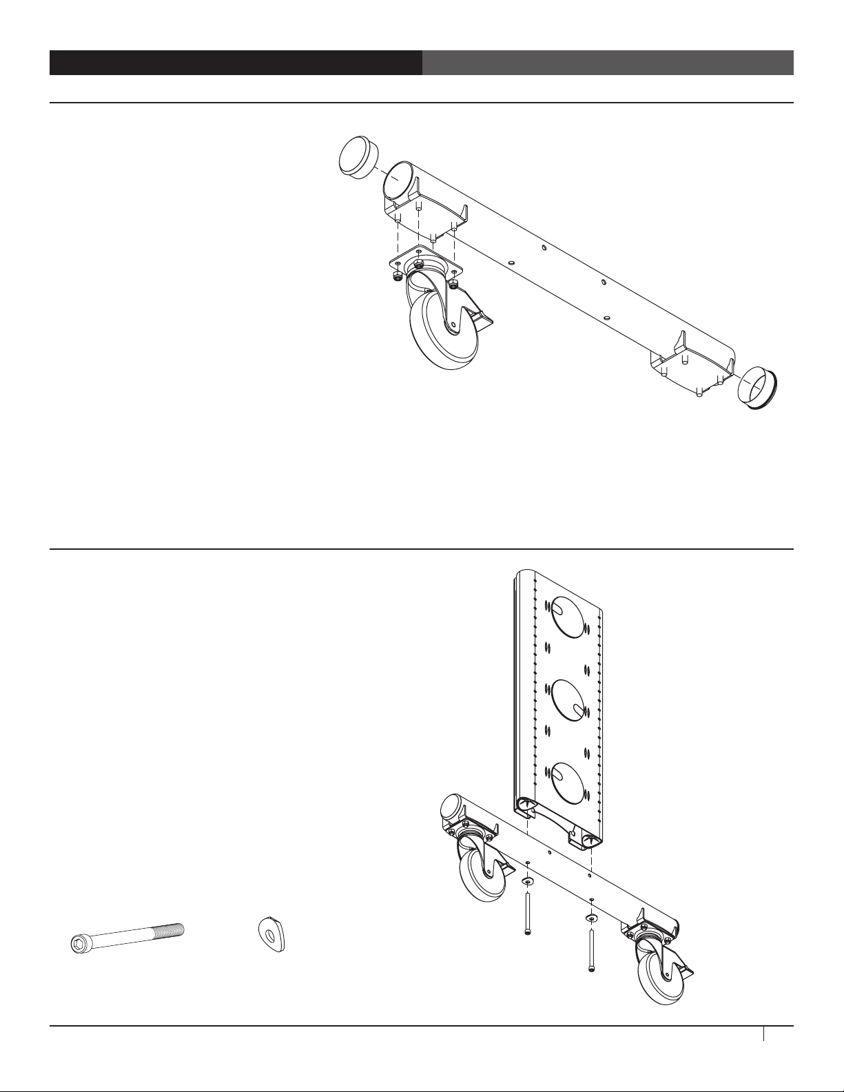
STEP 1
Install Casters
¡ Align the holes on one caster plate with
the threaded pegs on the bottom of the
Base Tube. Using the 3-way Wrench or a
9/16" wrench or socket, securely attach
the caster to the Base Tube.
¡ Repeat for the remaining three casters.
¡ Pop End Caps into the Base Tubes. Use
the mallet to set them into place.
Base Tube
with Caster Plate
Caster
End Cap
STEP 2
Attach the Leg Assemblies to the Base Tubes
¡ Align one Leg Assembly above one Base Tube
Assembly with the casters on the bottom.
¡ Using the 1/4" Hex Key, secure the Leg Assembly
to the Base Tube with a Bench Cap Screw and
Curved Washer. Make sure the curve on the
washer matches the curve of the base tube.
¡ Repeat for the other Leg Assembly and Base Tube.
Bench Cap Screw
325-5166-00
Curved Washer
225-3522-00
Leg Assembly
Utility Bench II Assembly Instructions
3
Page 4

STEP 3
Add the Cross Tubes
NOTE: This is a 2-person step. One person holds the
Cross Tubes while the other drives the Cap Screws.
¡ Position the Right Leg Assembly (from Step 2) with
two Cross Tubes as shown. Insert one Bench Cap Screw
with a Curved Washer through a side hole, carefully
threading the Screw into the Cross Tube.
¡ Repeat for the remaining three side holes.
Cross Tubes
Bench Cap Screw
325-5166-00
Curved Washer
225-3522-00
STEP 4
Determine the Shelf Height
¡ These instructions will place the Shelf at 35" above
the floor (with the 5" casters). The holes along the Leg
Assemblies are spaced at 1" increments. Adjusting one
hole down on the Leg Assembly will make the Shelf
34" above the floor.
NOTE: The Shelf height can be adjusted later if
needed; steps 5-8 will need to be disassembled
and reassembled again.
35"
4
Questions? Call us at 800.325.3841 or visit anthro.com. We’re happy to walk you through the assembly!
Page 5

STEP 5
Install the Arms
¡ Position one Utility Bench Arm onto a Leg Assembly.
¡ Align the top two openings of the Arm with Hole 2
of the Leg Assembly. Loosely install a Self-threading
Screw through the top two holes of the Arm and into
the Leg.
¡ Install the remaining six Self-threading Screws into
the Arm, but do not fully tighten.
¡ Repeat for the second Arm.
Utility Bench Arm
Self-threading Screw
325-5010-00
STEP 6
Install the Bench Pans
¡ Position a Bench Pan between the Arms, aligning the
two tabs on each Arm with the two holes on the lower
corners of the Pan. Insert a Pan Screw through the Pan
and the Arm Tab and capture it with a Keps Nut (but
do not fully tighten). Tighten with the 3-way Wrench.
¡ Repeat for the other end of the Pan and for both ends
of the second Pan.
Keps Nut
325-5130-03
Bench Pan
Pan Screw
325-5003-00
Utility Bench II Assembly Instructions
5
Page 6

STEP 7
Install the Shelf
NOTE: This is a 2-person step.
¡ Place the Utility Bench Shelf upside down onto the
floor. (Providing a soft surface will protect the finish
on the Shelf.)
¡ With the help of a second person, carefully rotate
the Leg Assembly onto the Shelf.
¡ Align the holes on the Pans and Arms with the
pre-drilled holes on the Shelf. Insert Wood Screws
through the center openings of each Bench Pan.
¡ Install the remaining Wood Screws into each of the
Arms and Pans. A total of twelve 1" Button-head PB
Screws will be installed.
¡ With the help of a second person, carefully rotate
the Utility Bench back onto its casters.
1” Button Hd PB Screw
325-5580-00
STEP 8
Install the Buttresses
¡ First, align one Buttress with one hole in the Back Pan.
Install a Pan Screw through the Buttress and loosely
capture it using a Keps Nut.
¡ Next, position one Cross End Bracket on the other end
of the Buttress and install a Pan Screw and Keps Nut
in the same manner, but do not fully tighten.
¡ Now, rotate the Buttress to align the Cross End Bracket
with two openings on the Leg. Secure the Cross End
Bracket to the Leg using two Self-threading Screws.
¡ Finally, repeat for the other three Buttresses and
tighten all the fasteners.
Congratulations! Your assembly is complete!
Buttress
Pan Screw
325-5003-00
6
Keps Nut
325-5130-03
Questions? Call us at 800.325.3841 or visit anthro.com. We’re happy to walk you through the assembly!
Self-threading Screw
325-5010-00
Page 7

Anthro Corporation® | 10450 SW Manhasset Dr. | Tualatin, OR 97062
Toll-free: 800.325.3841 | Fax: 800.325.0045 | email: sales@anthro.com | anthro.com
Outside the U.S. | Tel: 503.691.2556 | Fax: 503.691.2409
300-5600-00
300-5600-00
The Utility Bench II has a Lifetime Warranty.
Technology Furniture is a trademark of Anthro Corporation. Anthro reserves the right to modify the design and specifications without prior notice.
Warranty:
Notices:
 Loading...