

Page 1
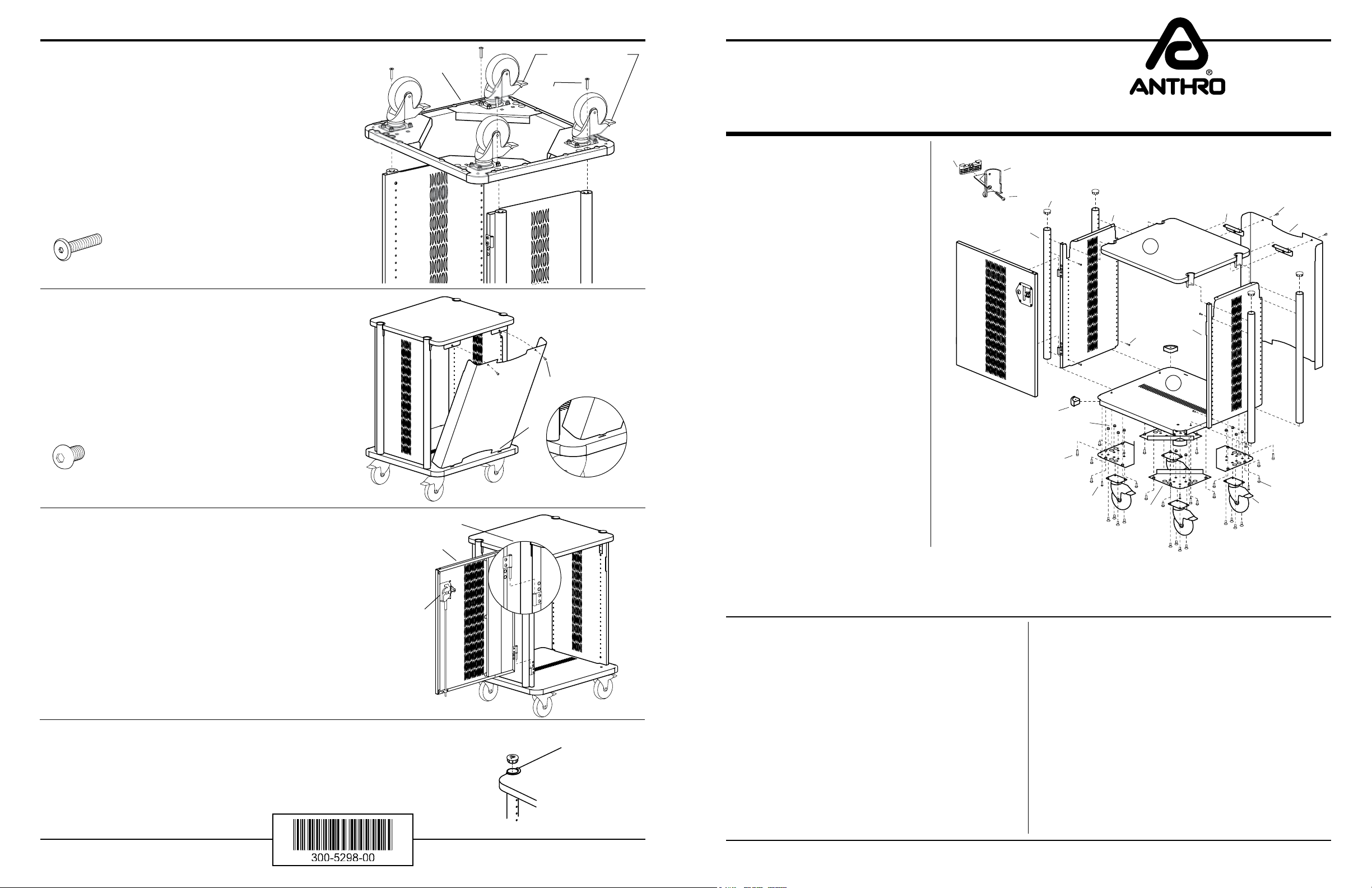
Step 8
Place the Metal Base Assembly onto the legs. Check the
orientation of the Base Assembly. Casters with the Green
Brake Pedals should face either the left or the right. Also,
the slots on the metal base (used for installing the Back Panel)
should align with the Panel Hangers on the wood shelf.
Align Vertical Legs with corner holes in the Base Assembly.
Insert a Funnel Head Screw through the Base and carefully
thread into the Leg.
Repeat for other three corners and tighten all screws.
Funnel Head Screw
325-5245-00
Step 9
Rotate your Cart upright.
Facing the rear of the Cart, orient the Back Panel so the
tabs are towards the bottom.
Carefully insert the two small tabs at the bottom of the
Back Panel into the slots on the Metal base. Tilt the top of
the Back Panel towards the Cart to meet the Panel Hangers. Secure using two Panel Screws.
Base Assembly
Back Panel
(Green Brake Pedal)
Funnel Head
Screw
Panel Screw
Tabs
Security Cart 24" Wide
Assembly Instructions
These Assembly Instructions
are for the SEC24xx/xx.
Before beginning assembly of your
Security Cart, please take a moment to
review the parts listed below to verify
that your shipment is complete.
It may also be helpful to review
the Assembly Instructions of all
Anthro Products you purchased
and are planning to include in
this installation.
To make the assembly of your Security
Cart even easier, we have included all of
the required tools. The handy Hex Driver
Bit can be used in your electric drill in
place of the Hex Driver.
Hex Driver 5/32" ....... 375-5000-00
3-Way Wrench ...........225-5196-00
Hex Key 3/16" ............375-5028-00
01
02
03
05
04
06
18
14
TECHNOLOGY FURNITURE
07
08
20
19
21
09
®
10
11
Panel Screw
325-5196-00
Step 10
Orient the Door so that the Lock Assembly is at the top.
Hinge Attachment
Detail
Door
Back Panel
Mount Detail
With the Door in the open position (as shown), align the
pins on the Door Hinges with the Hinges on the Cart
and slide down into place.
Lock Assembly
Step 11
1.5" End Cap
Pop the 1.5" End Caps into the tops of the Legs.
Congratulations! Your assembly is complete.
Questions? 1-800-325-3841
NOTE: When using a power drill
during assembly, ALWAYS begin
threading fasteners by hand!
Enclosed Parts List
Detailed views of all Hardware is provided with each Assembly Step.
01– Shelf Clamp ...................................Qty. 4 .........................175-5059-00
02– Shelf Support ........................ Qty. 4 .........................175-5060-00
03– Clamp Screw .............................. Qty. 4 .................. 325-5086-00
04– Door ............................................ Qty. 1 ................. 835-5040-00
05– 30" Vertical Legs ................... Qty. 4 .........................125-5267-00
06– 1.5" End Cap .............................. Qty. 4 .........................175-5020-00
07– Side Panel X ......................... Qty. 1 ........................225-5948-00
08– 24" Wide Shelf ......................... Qty. 1 .........................100-6512-00
09– Panel Hanger ....................... Qty. 2 .........................225-5950-00
10– Panel Screw ................................ Qty. 4 .........................325-5196-00
11– Back Panel ................................... Qty. 1 .........................225-5941-00
12– Cap Screw .................................. Qty. 32 .......................325-5188-00
13– 5" Rhombus Casters ................. ........................................ (see below)
Swivel Lock Caster ................... Qty. 2 .........................150-5080-00
Total Lock Caster .....................Qty. 2 .........................150-5081-00
Anthro® Corporation Technology Furniture® 10450 SW Manhasset Drive Tualatin, Oregon 97062
June 2006 Rev C
SAVE THESE INSTRUCTIONS!
17
12
16
15
13
14– Lock Nut ..................................... Qty. 16 .......................325-5263-00
15– Caster Mount Bracket ........... Qty. 4 ...........225-0585-04-02-00
16– 3/4" Wood Screw .....................Qty. 12 .......................325-5106-00
17– Funnel Head Screw ................... Qty. 4 .........................325-5245-00
18– Corner Bumper ......................... Qty. 4 .........................175-5112-00
19– Support Screw ........................... Qty. 12 .......................325-5010-00
20– Side Panel Y .......................... Qty. 1 .........................225-5949-00
21– Metal Base ........................... Qty. 1 .........................225-5943-00
All Screw quantities listed here are the minimum needed
for your Cart assembly. There may be a few extra Screws
included, which are not counted in the Parts List.
1-800-325-3841
Page 2
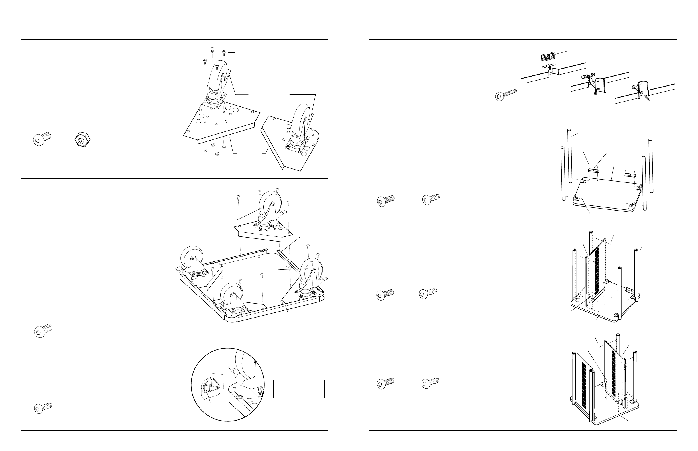
Base Assembly
Cart Assembly
Step 1
Secure a Caster to a Caster Plate using four 3/4" Cap Screws
and Lock Nuts per Caster.
Repeat for remaining Casters, Caster Plates, Bolts, and Nuts.
Cap Screw
325-5188-00
Nylon Lock Nut
325-5263-00
Step 2
Place the Caster Plates with the Green Brake Pedals onto one
side of the Metal Base, sliding each Plate under the anges on
the Metal Base. Secure using four Cap Screws.
Install the remaining Caster Plates on the other side.
Double-check the installation of the Swivel Lock Casters
(green brake pedal) by positioning the Caster Plates as shown.
Now depress the Brake. If it is installed correctly, the
Caster will be parallel with the Metal Base (as shown).
Lock Nut
Cap Screw
Swivel Lock Casters
(Green Brake Pedal)
Cap Screw
(Green Brake Pedal)
Inside Edge
Swivel Lock Casters
(Green Brake Pedal)
Rear Edge of
Metal Base has
four small holes
along edge.
Step 4
Attach four Shelf Supports to the Top Shelf. Begin by rst
installing a Clamp into the Shelf notch. Be sure the pointed
Barbs face towards the outer Shelf edge.
Next slide a Shelf Support into the recesses of
the Clamp and Shelf. Push in as far as possible.
Finally, secure with a Clamp Screw
Clamp Screw
325-5086-00
Step 5
Loosely attach the 24" Wide Shelf to the second hole from the
top (uncapped end) of each Vertical Leg using a Support Screw.
Next, align the two openings on each of the Panel Hangers with
those on the Shelf. Secure into place using two Wood Screws
through the Bracket into the Shelf.
Repeat for other Panel Hanger.
Support Screw
325-5010-00
3/4" Wood Screw
325-5106-00
Step 6
Align one vertical leg so that the end with the Star Nut
inside is facing up. Loosely attach the 24" Wide Shelf to
the second hole down using a Support Screw.
Next, align each Panel Hanger with the pre-drilled holes
on the shelf. Secure in place using two Wood Screws.
First
Barbs
Vertical Legs
Wood Screw
Side Panel Y
Next
Final
Panel Hanger
24" Wide Shelf
Support Screw
Support Screw
Vertical Leg
Cap Screw
325-5188-00
Step 3
Slide the Plastic Corners between the Metal Base and
Caster Plates, securing with one 3/4" Wood Screw
through each Bracket into the Plastic Corners.
3/4" Wood Screw
325-5106-00
Anthro® Corporation Technology Furniture® 10450 SW Manhasset Drive Tualatin, Oregon 97062
Wood Screw
Hollow side
face up
Metal Base
ange
Caster Bracket is
positioned BELOW
the ange
Support Screw
325-5010-00
3/4" Wood Screw
325-5106-00
Step 7
Install the Side Panel X (with hinges) using the same
procedure described in Step 6.
Repeat for Side Panel X (with hinges).
Support Screw
325-5010-00
3/4" Wood Screw
325-5106-00
Wood Screw
24" Wide Shelf
Support Screw
Side Panel X
Wood Screw
24" Wide Shelf
www.anthro.com
 Loading...