

Anthro Fit Standard Unit 24, Fit Standard Unit 30, Fit Standard Unit 36, Fit Standard Unit 48 Assembly Instructions
Page 1
R
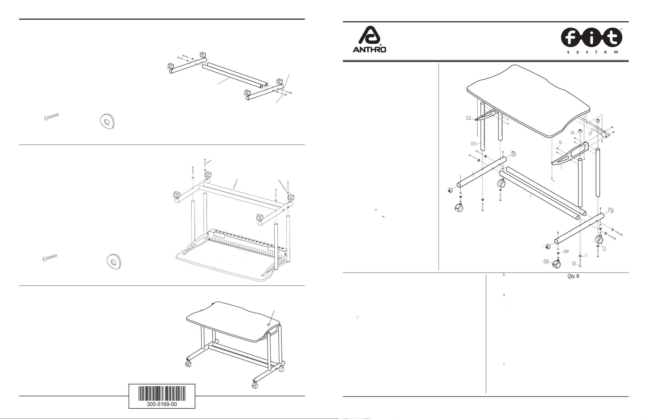
01–Worksurface
...............................
Qty. 1
.......................
(see below)
24” Wide Worksurface
(F24029zz/xx3)
............
30” Wide Worksurface
(F3029zz/xx3)
...............
36” Wide Worksurface
(F3629zz/xx3)
...............
48” Wide Worksurface
(F4829zz/xx3)
...............
02– Support Bracket-B
....................
Qty. 1
...................
225-2296-00
fi t
Small Support Y
(F2429zz/xx3)
..
Qty. 1
...................
225-2015-00
03– 22.875” Vertical Legs
.................
Qty. 4
...................
04– Base Tubes
.......................................
Qty. 2
..................
05– Cross Tubes
................................
Qty. 2
.......................
(see below)
24” Deep Base Tube
(F2429zz/xx3)
....................
30” Deep Base Tube
(F3029zz/xx3)
....................
36” Deep Base Tube
F3629zz/xx3)
......................
48” Deep Base Tube
(F4829zz/xx3)
....................
06– Insert Screws
.............................
Qty. 4
...................
325-5052-00
07– 2” Large End Caps
....................
Qty. 4
...................
08– 3” Locking Casters
...................
Qty. 2
...................
09– Caster Inserts
............................
Qty. 4
...................
525-5032-00
Component list for part #’s
/
Bolts
..........................
...................
Tube Washers
.......................
..
225-2050-00 or 225-3522-00
.........
...................
/
......................
...................
....................
.................
225-2295 -00
Small Support X
..
...................
225-2014-00
.........................
...................
.........................
...................
................................
.......................
24” Wide Back Trough
................
30” Wide Back Trough
................
36” Wide Back Trough
................
48” Wide Back Trough
................
/4 ....
...................
All Screw quantities listed here are the minimum needed
Screws included, which are not counted in the Parts List.
Anthro
®
10450 SW Manhasset Drive Tualatin, Oregon 97062 anthro.com
SAVE THESE INSTRUCTIONS!
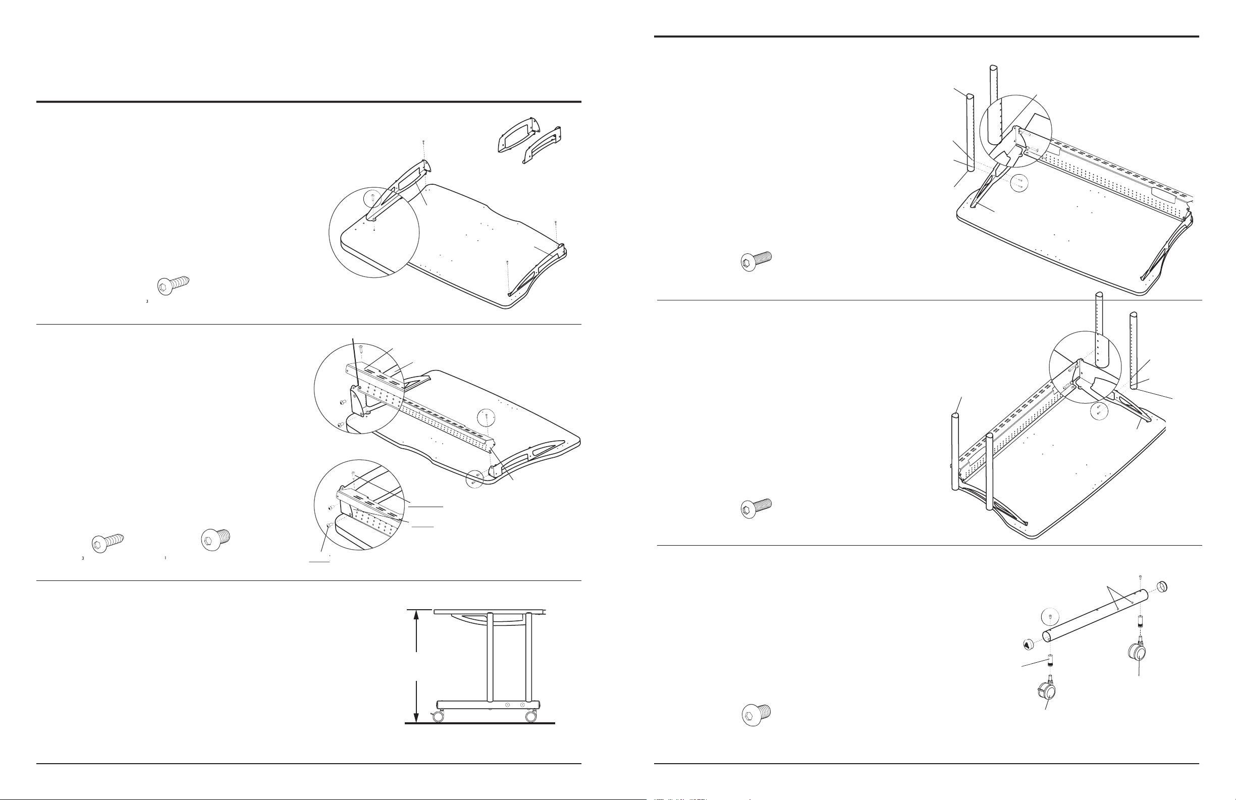
Align the Base Assembly on the Vertical Tubes as shown.
Bolt through a
Your assembly is complete.
the required tools. The handy Hex Driver
/
.........
/
....
....
/
fi t
fi t
Tube Washer
Assembly Instructions
provided with each Assembly Step.
Attach a Cross Tube to a Base Tube by inserting a
fi t
Bolt
through a Tube Washer, then insert the Bolt through
the
fi t
fi t
Tube Washer
/
fi t
Bolt
Page 2
Anthro
®
10450 SW Manhasset Drive Tualatin, Oregon 97062
Small Support X & Y, to be used in place of the
Attach a Vertical Leg by
through the Support Bracket-A into holes 1 & 3 from the
top
of a Leg.
Align the two threaded holes on each end of the Back
thread one Button Head Screw through the Support
predrilled holes on the Worksurface)
and tighten into place.
Attach the remaining Vertical Legs to Support Bracket-B
/
4
/
4
/
Support Bracket-B
: Install the Button Head Screws
SECOND:
Support Bracket-A
Support Bracket-B
Support Bracket-A
Support Bracket-B
: Make certain to install the Back
Assembly Instructions
fl oor using the standard 3” casters.
 Loading...