

Page 1

ASSEMBLY INSTRUCTIONS
CAUTION
Moving parts
can crush.
Use care when
operating.
ElevateTM Original Corner
Part Number: ELBCzz-xx4
Anthro Corporation® | 10450 SW Manhasset Dr. | Tualatin, OR 97062
Toll-free: 800.325.3841 | Fax: 800.325.0045 | email: sales@anthro.com | anthro.com
Outside the U.S. | Tel: 503.691.2556 | Fax: 503.691.2409
November 2013
CAUTION
This table holds up to 300 lbs.
of distributed weight and
90 lbs. over one leg.
Page 2
25
38
40
27
04
42
29
30
34
37
26
18
24
19
01
17
26
08
41
39
13
21
15
14
16
20
05
23
10
22
1112
09
03
28
31
WELCOME
Thank you for purchasing Elevate,™Corner! If you have
any questions or if we can help you in any way, please
contact us at 800.325.3841.
This assembly requires two people.
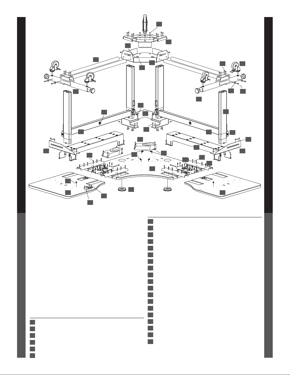
PARTS LIST
Before beginning assembly of your Table, please take a
moment to review the parts listed below to verify that
your shipment is complete. A Phillips head screwdriver
is required for this assembly. A 7/16" Socket with
extension and wrench will make this assembly go more
smoothly. A 7/16" Open-end Wrench or Adjustable
Wrench are useful substitutions.
Product Quantity Part Number
01 Center Shelf 1 101-1143-01-00
02 Side A Wing Shelf 1 101-1145-01-00
03 Side B Wing Shelf 1 101-1146-01-00
04 Cross Tube 4 125-5317-00
05 4" Locking Caster 6 150-5065-00
2
06 Velcro Tie (not shown) 4 175-5121-03
07
Product Quantity Part Number
07 3.5" Grommet 2 175-5147-00
08 Basetube End Cap 4 175-5158-32
09 Wire Managment Clip 3 175-5188-00
10 Crosstube End Cap 4 175-5190-32
11 Shelf Gusset (X) 1 225-2269-00
12 Shelf Gusset (Y) 1 225-2270-00
13 Cableway 2 225-2282-00
14 Junction Plate 4 225-2463-00
15 Draw Latch Plate X 2 225-4785-00
16 Draw Latch Plate Y 2 225-4786-00
17 Leg Plate 1 225-2565-00
18 Corner Gusset 1 225-2566-00
19 Corner Shelf Cap 1 225-2567-00
20 Curved Washer 4 225-3522-00
21 3/4" Button Head PB Screw 8 325-5575-00
22 1/2" Button Head Cap Screw 12 325-5003-00
23 4" Cap Screw 4 325-5166-00
24 3.5" Bolt 8 325-5194-00
25 1/4-20 Lock Nut 2 325-5259-00
(CONTINUED NEXT PAGE)
02
Page 3
PARTS LIST (CONTINUED)
Product Quantity Part Number
26 20mm Socket Head Cap Screw 16 325-5272-00
27 #6-9x1" Flat Hd Screw 44 325-5716-00
28 3/4" Phillips Head Screw 4 325-5370-00
29 Flat Washer 4 325-5379-00
30 Zip Tie Screw Mount 4 400-5152-00
31 Keypad Assembly 1
Keypad 400-5357-00
Keypad Slider 400-5358-00
32 2-meter Control Box Cable 1 400-5180-00
(not shown)
33 1-meter Control Box Cable 3 400-5182-00
(not shown)
34 Control Box 2 400-5215-00
35 Zip Tie Panel Mount 2 400-5239-00
36 10' Power Cord Y (not shown) 1 400-5240-00
37 Patch Cable (not shown) 1 400-5241-00
38 Basetube 2 500-1005-00
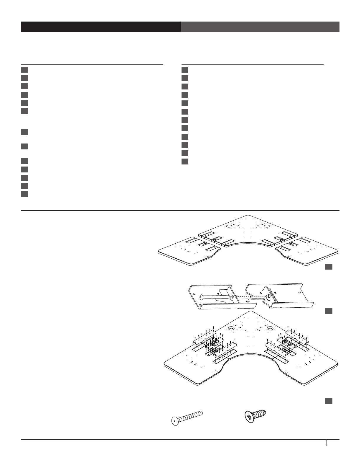
STEP 1
Assemble the Worksurface
Product Quantity Part Number
39 Cross Tube (X) 1 500-5024-00
40 Cross Tube (Y) 1 500-5025-00
41 Leg 4 575-5018-00
42 Anthro Medallion 2 725-5014-00
43 Anthro 3 Way Wrench (not shown) 1 225-5196-00
44 Hex Driver (not shown) 1 375-5000-00
45 5/32" Hex Driver Bit (not shown) 1 375-5003-00
46 5mm Hex Key (not shown) 1 375-5014-00
47 Rubber Mallet (not shown) 1 375-5022-00
48 5mm Hex Key (not shown) 1 375-5014-00
49 1/4" Hex Key (not shown) 1 375-5024-00
50 #2 Phillips Bit (not shown) 1 375-5009-00
Place the three worksurface components
upside down on a non-marring surface. Align
each wing to the corner piece so the curved
outer edges line up and the channels at the
center of each piece meet. [A]
Align the two halves of each latch assembly so that
the threaded bolt hole on one half of the assembly
aligns with the unthreaded bolt hole. Loosely connect
the two halves of the assembly by driving one
3.5" Bolt through the unthreaded hole and into the
threaded hole. [B]
Place one latch assembly into the center slot of the
three slots where the corner worksurface component
meets one of the wings. Align the screw holes in the
latch assembly with the holes on the worksurface
components.
Attach the latch assembly to the tops with #6-9x1"
Flat-hd Screw using a Phillips screwdriver, then tighten
the 3.5" Bolt just as tight as it will go. Loosely install two
junction plates in the slots surrounding the latch
assembly with six more #6-9x1" Flat-hd Screws. [C]
Repeat for the second latch assembly and junction
plates on the other wing.
Tighten all Phillips screws.
3.5” Bolt
325-5194-00
A
B
C
#6-9x1” Flat-Hd Screw
325-5716-00
ElevateTM Original Corner Assembly Instructions
3
Page 4

STEP 6
Assemble the Outside Legs
Align a leg with the opening on the base tube so that the
welded slot bracket on the legs is facing the hole on the base
tube and that the cord comes out the top.
Shelf Gusset (X) Shelf Gusset (Y)
Attach with four Socket Head Cap Screws.
Repeat for the other leg.
Align each shelf gusset with a leg as shown so that the
side of the gusset doesn't block the cord.
Attach each shelf gusset to a leg with four Socket
Head Cap Screws.
STEP 7
Assemble the Corner Leg Assembly and Install
Align a leg with the inside of the Corner Gusset so that
the Slot is facing the open corner and the cord goes to
the inside. Attach using eight Socket Head Cap Screws.
Slot Slot
Rear
Front Front
20mm Socket Head Cap Screw
325-5272-00
20mm Socket Head Cap Screw
325-5272-00
Repeat for the second leg.
Align the Corner Leg Assembly with the hole array on
the Top. Make sure that the cords are to the inside.
Secure the Leg Assembly to the Top Assembly using
1" Button-hd PB Screws.
1” Button Hd PB Screw
325-5580-00
Slot
4
Questions? Call us at 800.325.3841 or visit anthro.com. We’re happy to walk you through the assembly!
Page 5

STEP 8
Assemble the Corner Base Assembly
Attach a pair of Cross Tubes to one side of the Corner
Shelf Cap using two Flat Washers and two 3.5" Bolts.
Tighten the fasteners all the way.
Repeat for the second pair of Cross Tubes.
Align the Leg Plate over the Corner Shelf Cap and slide
into place. Using a 7/16" socket, open end wrench,
adjustable wrench, or the Anthro three-way wrench,
tighten four Lock Nuts onto the threaded pins.
Secure the side of the Leg Plate to the Corner Shelf
Cap using 1/2" Button Head Cap Screws. Drive the
screws from the outside in.
Lift this Corner Base Assembly over the center legs and
seat them in place, but don’t attach them!
STEP 9
Install the Outside Leg Assemblies
1/2" Button Head Cap Screw
325-5003-00
A
3.5" Bolt
325-5194-00
Lock Nut
325-5259-00
Flat Washer
325-5379-00
Align one Outside Leg Assembly with the hole array on
the Top Assembly. Make sure that the Leg Gusset is to the
outside of the table and the cable is to the inside of the
table. Also verify that the slot on the leg lines up with the
hole in the base tube. (See the image on Step 6.)
Tilt this Outside leg Assembly into place with the top of
its Cap Screws seated into the notches on the shelf. But
don't attach with wood screws...not yet. [Image A]
Loosely attach the Cross Tubes into this Leg Assembly
using 4" Cap Screws and Curved Washers. Make sure that
the curves at the ends of the Cross Tubes line up with the
round Base Tube. [Image B]
Repeat for the other outside leg.
ElevateTM Original Corner Assembly Instructions
B
4" Cap Screw
325-5166-00
Curved Washer
225-3522-00
5
Page 6

STEP 10
Connect the Legs to the Corner Base Assembly
Using the 3/16" Hex Key, loosely attach
the Corner Base Assembly to the Legs
with Socket Head Cap Screws.
Using the 5/32" Hex Driver (or the 5/32"
Hex Bit and your electric driver/drill),
attach the Outside Leg Assemblies to
the top with 1" Button-hd PB Screws.
20mm Socket Head Cap Screw
325-5272-00
Tighten all the screws except the
outside screws on the Cross Tubes.
STEP 11A
Install Control Boxes, Key Pad,
and Connect Cables
Align one Control Box with the hole pattern
on the Top Assembly inside the Corner Gusset.
Secure using four 3/4" Button-hd PB Screws.
Align another Control Box with the hole
pattern on either side of the Top Assembly in
between the Corner Gusset and the Junction
Plate. Secure using 3/4" Button-hd PB Screws.
Connect the Leg Cables to the Control Boxes.
Send the short cables to the closer legs and
the long cable to the furthest outside leg.
Connect the two Control Boxes with the
Patch Cable.
Align the Keypad and its housing with the four
pre-drilled holes at the front of the table so
that the buttons are face-down at the front
edge of the table and the flat side of the
housing is against the shelf. Using four silver
3/4" Phillips Head Screws, attach the Keypad
and its housing to the table.
1” Button Hd PB Screw
325-5580-00
3/4" Button Hd PB Screw
325-5575-00
Wire Managment Clip
Keypad Detail
3/4" Phillips Head Screw
325-5370-00
Plug the power cords into the control boxes.
STEP 11B
Install Cable Ties
Insert Cable Clips into the Table and route
cords through them. Make sure that cords
will clear sharp edges and pinch points when
the legs are in motion.
Plug the Keypad Cable into the Control Box.
Insert a Cable Clip into the Table and route the
cable through it.
6
Questions? Call us at 800.325.3841 or visit anthro.com. We’re happy to walk you through the assembly!
Zip Tie Panel Mount
Zip Tie Screw Mount
Page 7

STEP 12
Install the Cable Troughs
Align each cable trough with the flanges on
each leg gusset and the pre-drilled holes on
the shelf. Before installing the trough, make
sure that cables are routed through the ends
of the trough, not into the side of the trough.
Secure the troughs to the gussets with Button
Head Cap Screws. Secure the troughs to the
shelf using 1" Button-hd PB Screws.
1” Button Hd PB Screw
325-5580-00
1/2" Button Head Cap Screw
325-5003-00
STEP 13
Install casters and turn it over!
Thread casters into the inserts in each leg. This is a lot easier if you lock the
casters first.
With the help of another person, carefully rotate the Table onto its casters.
Plug the power cord into the Control Boxes and an outlet. Insert a cable clip into
the base tube closest to the Control Boxes and route the power cord through it.
Cable Snap-in Clip
175-51188-00
STEP 14
Cross Bars
Using the keypad, move the shelf all
the way up. (Check the legs for excess
lubricant and wipe down if needed.)
Align one Cross Bar so that the tapered
ends of the cross bar brackets line up
with the leg brackets. Using the mallet,
drive the Cross Bar completely into
place (a few whacks on the left, a few
on the right, then left, then right…).
Repeat for the second Cross Bar.
Tighten the outside screws on the
Cross Tubes.
ElevateTM Original Corner Assembly Instructions
7
Page 8

STEP 15
Home the legs
Press down button until the table reaches its lowest point and stops moving. Release the button for 1-2 seconds. Press
down button again for 3-5 seconds and you will see the table home itself.
Press up button until the table tops at the highest point and hold for 3-5 seconds. Press the down button for 2-3
seconds, then the up button again until it tops at the highest point and hold again for 3-5 seconds. (The goal is to have
the table hold at it’s highest point twice.)
If the legs ever fail to function properly, unplug the power cord, wait 10 seconds, plug the power cord back in and repeat
the above steps.
Legs must also be homed any time that power is disconnected from the legs.
If the legs are not homed at both the top and the bottom, the table will only move at half its normal speed.
STEP 16
Add Accessories and Install Your Equipment
Now add your Anthro accessories and install your equipment.
A word of caution: the height range of Elevate may be longer than the cords on your equipment. Equipment that is
mounted in a SideRack w/Caster or Equipment Shelf, for example, will not move up and down with the table. Raise and
lower the table to its highest and lowest positions when all equipment is installed to make sure that the cords are long
enough. Double-check that all the table's cords and cables reach comfortably through the table's entire range of motion.
STEP 17
Insert Grommets and End Caps
Slip the grommet covers into place. (Gently
whack them with the mallet if they’re stubborn.)
Pop end caps into the cross bars and base tubes.
Use the mallet to set them into place.
Congratulations! Your assembly is complete!
Elevate Original Corner has a Lifetime Warranty against manufacturing defects, two years for the electrical system. Cords and plugs
End Cap
Technology Furniture and Elevate are trademarks of Anthro Corporation. Anthro reserves the right to modify the design and
Grommet
*300-5596-00*
300-5596-00
Warranty:
are not warranted.
Notices:
specifications without prior notice.
8
Questions? Call us at 800.325.3841 or visit anthro.com. We’re happy to walk you through the assembly!
 Loading...