

Page 1
ASSEMBLY INSTRUCTIONS
Elevate™ Adjusta
Product Part#
Elevate Adjusta 60w ELTAD60zz/xx4
Elevate Adjusta 48w ELTAD48zz/xx4
Anthro Corporation® | 10450 SW Manhasset Dr. | Tualatin, OR 97062
Toll-free: 800.325.3841 | Fax: 800.325.0045 | email: sales@anthro.com | anthro.com
Outside the U.S. | Tel: 503.691.2556 | Fax: 503.691.2409
Ref F, January 2013
Page 2
04
02
11
01
WELCOME
Thank you for purchasing this Elevate Adjusta! If
you have any questions or if we can help you in
any way, please contact us at 800.325.3841.
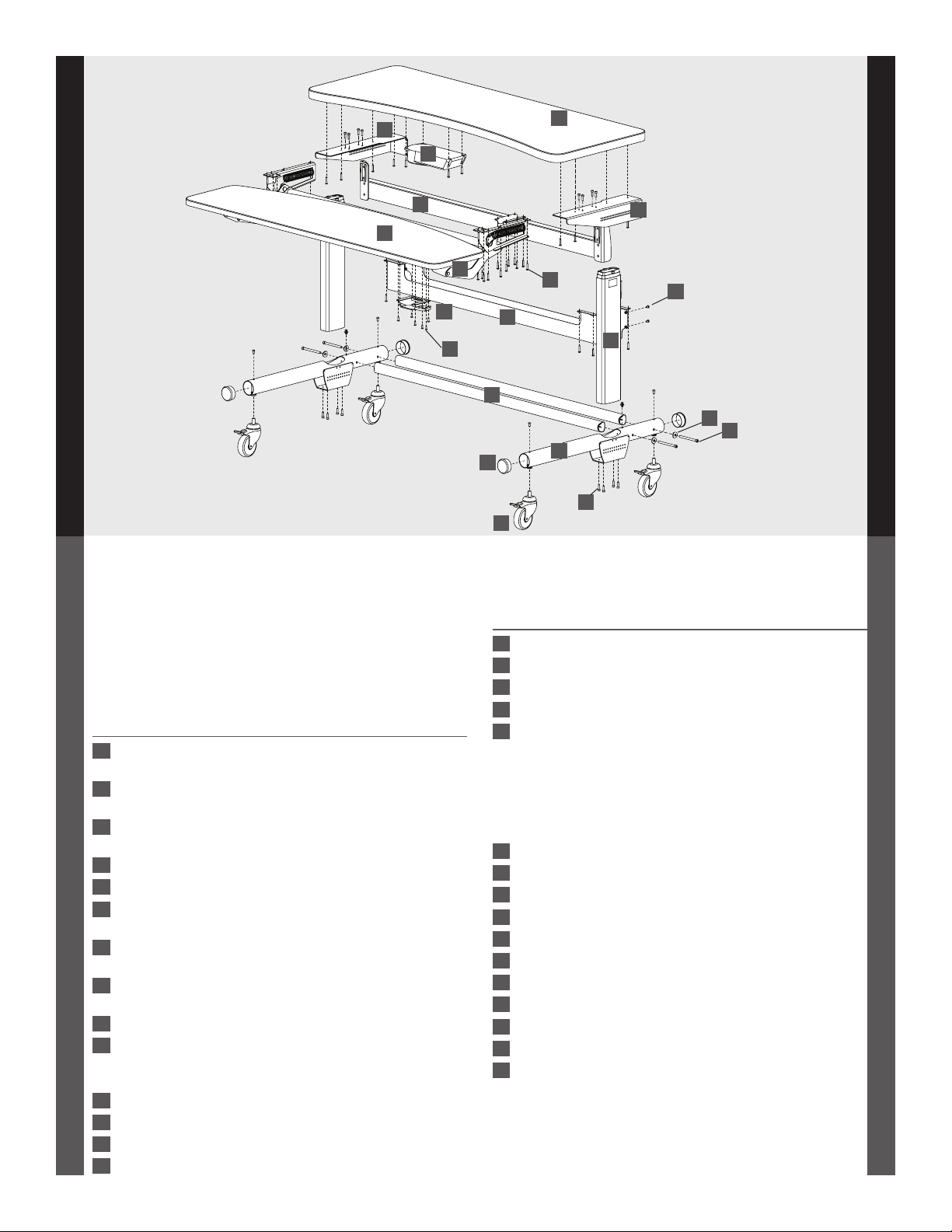
PARTS LIST
Before beginning assembly, please review the parts list
to verify that your shipment is complete.
Product Quantity Part Number
01 Keyboard Shelf, 60w 1 100-A308-02-02-00
Keyboard Shelf, 48w 1 100-6643-00
02 Monitor Shelf, 60w 1 100-A308-02-01-00
Monitor Shelf, 48w 1 100-6644-00
03 Cable Trough, 60w 1 225-2283-00
Cable Trough, 48w 1 225-2282-00
04 ELT Adjusta Shelf Gusset X 1 225-2269-00
05 ELT Adjusta Shelf Gusset Y 1 225-2270-00
06 Crossbar Assembly, 60w 1 500-A308-02-01-00
Crossbar Assembly, 48w 1 500-1044-00
07 Adjusta Mechanism, 60w 1 225-5548-00
Adjusta Mechanism, 48w 1 225-5547-00
08 Cross Tube, 60w 2 125-5185-00
Cross Tube, 48w 2 125-5184-00
09 Electric Leg 2 575-5018-00
10 Keypad Assembly 1
Keypad 400-5357-00
Keypad Slider 400-5358-00
11 Control Box 1 400-5393-00
12 Control Box Cable, 2m (not shown) 1 400-5180-00
13 Control Box Cable, 1m (not shown) 1 400-5182-00
2
14 Power Cable, 3.2 meter (not shown) 1 400-5181-00
06
05
07
10
24
08
17
16
03
20
15
23
09
21
19
22
PARTS LIST, CONTINUED
Product Quantity Part Number
15 Base Tube Assembly 2 500-A308-02-02-00
16 Locking Casters, 4" 4 150-5065-00
17 End Caps 4 175-5158-00
18 Wire Management Clips (not shown) 4 175-5188-00
19 Basetube Washers 4
Black 225-2050-03
Silver Metallic 225-3522-00
TOOLS and HARDWARE (Quantities shown are the minimum
required for this assembly; you may receive a few extras.)
20 Button-head Screw, 1" 68 325-5580-00
21 Button-head Cap Screw, 3/8" 4 325-5149-00
22 Cap Screw, 4" 4 325-5166-00
23 Socket-head Cap Screw, 20MM 12 325-5272-00
24 Phillips-head Screw, 3/4" 4 325-5370-00
25 Rubber Mallet (not shown) 1 375-5022-00
26 5/32" Hex Driver (not shown) 1 375-5000-00
27 5/32" Hex Bit (not shown) 1 375-5003-00
28 1/4" Hex Key (not shown) 1 375-5024-00
29 5MM Hex Key (not shown) 1 375-5014-00
30 3-way Wrench (not shown) 1 225-5196-00
Page 3
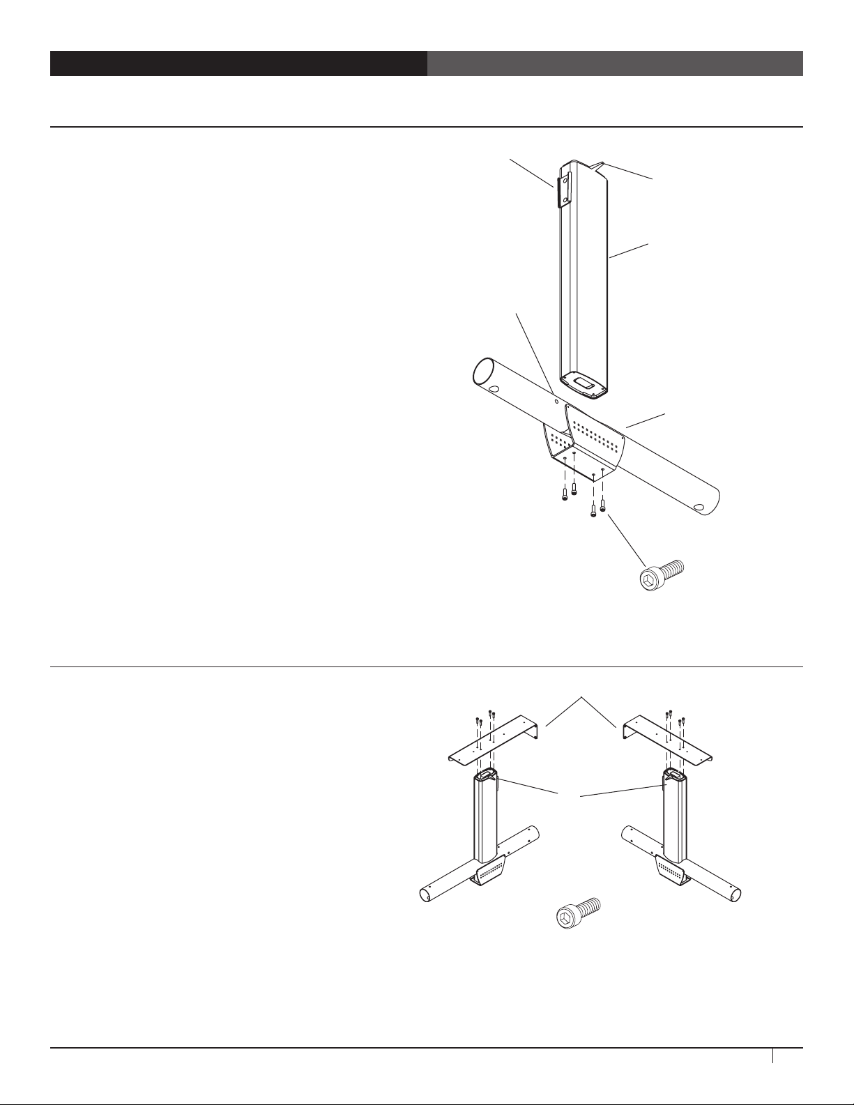
STEP 1
Attach the Legs to the Base Tubes
¡ Align a leg with the opening on the base tube so that
the slot on the leg is facing the hole on the base tube,
and the cord comes out the top.
¡ Attach with four Socket Head Cap Screws.
Slot
Cord
Leg
¡ Repeat for the second leg.
STEP 2
Attach Gussets to Legs
Hole
Rear
Basetube
Front
20mm Socket Head Cap Screw
325-5272-00
Back Bend
Shelf Gusset (X) Shelf Gusset (Y)
¡ Align a gusset with a leg so that the side flange is on
the outside, the cord is on the inside, the back bend is
over the rear of the tube, and the screw holes on the
top of the gusset match the threaded holes on the top
of the leg.
¡Secure each gusset to a leg with four socket-head cap
screws.
Elevate Adjusta Assembly Instructions
Cord
Rear
Front Front
20mm Socket Head Cap Screw
325-5272-00
3
Page 4

STEP 3
Attach Leg Assemblies to Shelf
¡ Place the work surface upside down on a cushioned non-marring
surface that's elevated about 12" above the floor. Stacking the table's
shipping box and the adjusta mechanism box works well (just remove
the mechanism first). Invert one leg assembly over the work surface
so the side flange is against the side of the work surface, the heads of
the cap screws at the top of the leg assembly rest in the recessed holes
in the work surface, and the holes in the gusset line up with the predrilled holes in the work surface.
¡Loosely attach with four 1" Button-head Screws. If you aren't installing
an Elevate SideRack 760zz, install additional screws through the four
open holes on the gusset. Don’t tighten all the way.
¡ Repeat for the other leg assembly.
If you have purchased an Elevate SideRack 760zz, install it now.
STEP 4
Attach Cross Tubes to Base Tubes
¡ Position the two Cross Tubes as shown. Insert one Cap
Screw with a Basetube Washer through a side hole,
carefully threading the Screw into the Cross Tube, but
Basetube Washer
225-2050-00 (Black)
225-3522-00 (Silver)
do not tighten all the way. Repeat for the remaining
three side holes.
¡ Once all cross tubes are installed, tighten all the
basetube screws. Leave the Wood Screws loose
until after Step 9, installation of the Cable Trough.
4" Cap Screw
325-5166-00
STEP 5A
Assemble Adjusta Mechanism
¡ Your Adjusta mechanism comes
unassembled and is boxed separately
inside the package. Locate the small bag
of hardware included with the Adjusta
Mechanism. It includes (1) Post, (1) Cotter
Pin, (2) Hex Nuts, (2) Wood Screws, and (2)
Cable Mounts.
¡ Begin to assemble the mechanism by first
locating the Crossbar and Brake/Paddle
assembly and position them as shown at
right. Depress the Paddle once to free the
Brake Shaft.
¡ Place the Brake Shaft between the two
center Crossbar flanges. Insert the Post
through both center Crossbar flanges and
the Brake Shaft.
¡ Install the Cotter Pin through the single
opening of the post to secure it in place.
(included with 225-5548-00)
(included with 225-5548-00)
Crossbar
Post
Cotter Pin
Brake Cable
Center Crossbar Flanges
Cotter Pin
1” Btn-Hd Screw
325-5580-00
Cross Tubes
Brake/Paddle Assembly
Brake Shaft
Post
4
Questions? Call us at 800.325.3841 or visit anthro.com. We’re happy to walk you through the assembly!
Page 5

STEP 5B
Align the Adjusta Mechanism
¡ Locate the two Adjusta Mechanism Arms.
Align each arm with the pre-drilled holes
on the Monitor Surface. Loosely attach one
Mechanism Arm with six 1" Button-head
Screws.
¡Align one end of the Crossbar Assembly
with the Threaded Pin and upper "button"
on the Mechanism Arms. Repeat for the
other end. Using the 3-way Wrench, secure
the Crossbar to the Mechanism Arms with a
5/16" Hex Nut onto the Threaded Pin.
Mechanism
Arm
Detail View
Crossbar
Brake/Paddle
Assembly
1” Btn-Hd Screw
325-5580-00
STEP 6
Attach Adjusta Mechanism to Monitor Surface
¡ Loosely attach the second Mechanism Arm
to the Monitor Surface using a total of six
1" Button-head Screws.
¡ Align the brake assembly with the six holes
on the Monitor Surface. It may be necessary
to depress the paddle in order to position
the brake.
¡ Secure the brake assembly with six 1"
Button-head Screws.
1” Btn-Hd Screw
325-5580-00
Wide View
Mechanism Arm
Elevate Adjusta Assembly Instructions
Mechanism Arm
5
Page 6

STEP 7
Attach Adjusta Mechanism to Keyboard Surface
¡ Slide the Keyboard Surface under the
mechanism arms. Align the three holes on
each end of the Keyboard surface with the
three holes on each mechanism arm. Secure
the arms to the Keyboard Surface with six
1" Button-head Screws.
¡ Position the Paddle on the Keyboard Surface
so the four holes on the Paddle align with
the four holes on the Keyboard Surface and
the brake cable runs under the Adjusta Bar.
Secure the Paddle to the Keyboard Surface
with four 1" Button-head Screws.
1” Btn-Hd Screw
325-5580-00
STEP 8
Install Keypad and Control Box
¡ Select positions for the Keypad and Control Box,
either the left or right side of the Table. Remember
that the Keypad and Control Box must be on the same
side of the Table. Also, the power cord comes off the
back of the Control Box and should be positioned so
it can reach the outlet.
¡ Place the Control Box on the shelf so that the cord
outlets are at the back, then align the Box with the
pre-drilled holes on the shelf. Secure with four
1" Button-head Screws.
¡ Select the position for the Keypad, on the same side of
the table as the Control Box. Align the Keypad and its
housing with the four pre-drilled holes at the front of
the keyboard surface so that the buttons are facedown at the front edge of the keyboard surface and
the flat side of the housing is against the shelf. Using
four Phillips Head Screws, attach the Keypad and its
housing to the front of the keyboard surface.
¡ Plug the leg cords into the Control Box. Use the
shortest cord to connect with the nearest leg. Insert
cable clips into the table and route leg cords through
them. Plug the keypad cable into Control Box. Insert a
cable clip into the table and route the cord through it.
Alternate
Keypad
Location
Keypad Detail
1” Btn-Hd Screw
Cable Snap-in Clip
325-5580-00
175-51188-00
Keypad
3/4” Phillips Screw
325-5370-00
6
Questions? Call us at 800.325.3841 or visit anthro.com. We’re happy to walk you through the assembly!
Page 7

STEP 9
Attach Cable Trough and Tighten All Screws
¡ Align the cable trough with the flanges on each leg
gusset and the pre-drilled holes on the monitor shelf.
Before installing the trough, make sure that cables are
routed through the ends of the trough, not into the
side of the trough. Secure the trough to the gussets
with four 3/8" Button-head Screws. Secure the trough
to the monitor shelf using eight 1" Button-head
Screws.
¡Tighten all the Wood Screws on the Cable Trough, the
Leg Gussets, and the Mechanism.
3/8" Screw
325-5149-00
1” Btn-Hd Screw
325-5580-00
STEP 10
Add Casters and Turn Table Right Side Up
¡ Thread casters into the inserts in each leg. This is a lot easier if you lock the casters first.
¡ With the help of another person, carefully rotate the table onto its casters.
STEP 11
Install Cross Bar & End Caps
¡ Using the keypad, move the table all the way up. Check the legs for
excess lubricant and wipe down if needed.
¡ Align the cross bar so that the tapered ends of the cross bar brackets
line up with the leg brackets. Using the mallet, drive the cross bar
completely into place (a few whacks on the left, a few on the right,
then left, then right...).
¡ Plug the power cord into the control box and an outlet. Insert a cable clip
into the base tube closest to the Control Box and route the power cord through it.
Cable Clip
Hole
Cable Snap-in Clip
175-51188-00
STEP 12
Home the Legs
¡ Press the Down button on the keypad three times, and hold down on the third time for about 5-10 seconds until you hear
a slight click and the table bumps up-down-up.
¡ If the legs fail to function properly, unplug the power, wait 10 seconds, plug the power back in and repeat the above step.
¡ Legs must also be homed any time power is disconnected from the legs.
STEP 13
Add Accessories and Install Your Equipment
¡ Now add your Anthro accessories and install your equipment.
¡ A word of caution: the height range of Elevate may be longer than the cords on your equipment. Equipment that is
mounted in a SideRack w/Caster or Equipment Shelf, for example, will not move up and down with the table. Raise and
lower the table to its highest and lowest positions when all equipment is installed to make sure that the cords are long
enough. Double-check that all the table's cords and cables reach comfortably through the table's entire range of motion.
Elevate Adjusta Assembly Instructions
7
Page 8

Anthro Corporation® | 10450 SW Manhasset Dr. | Tualatin, OR 97062
Toll-free: 800.325.3841 | Fax: 800.325.0045 | email: sales@anthro.com | anthro.com
Outside the U.S. | Tel: 503.691.2556 | Fax: 503.691.2409
*300-5473-00*
300-5473-00
Elevate Adjusta has a Lifetime Warranty against manufacturing defects, two years for the electrical system. Cords and plugs are not warranted.
Technology Furniture and Elevate are trademarks of Anthro Corporation. Anthro reserves the right to modify the design and specifications without prior notice.
Warranty:
Notices:
 Loading...