

Page 1

97055066
Rev. 00
2019-03
OPERATOR'S MANUAL
A5
- A6 PLUS
- L6
EN
.
Page 2

A5 - A6 PLUS - L6
2
EN
INDEX
1. GENERAL WARNINGS ................................................................................................................................................................................... 4
1.1. SYMBOLS ...................................................................................................................................................................................................4
1.2. INTENDED USE .........................................................................................................................................................................................5
1.2.1. CLASSIFICATION AND REFERENCE STANDARDS ........................................................................................................................6
1.2.2. ENVIRONMENTAL CONDITIONS......................................................................................................................................................6
1.2.2.1. STORAGE CONDITIONS ...................................................................................................................................................................6
1.2.3. WARRANTY .......................................................................................................................................................................................6
1.2.4. DISPOSING THE EQUIPMENT WHEN NO LONGER USED .............................................................................................................6
1.3. SAFETY WARNINGS ..................................................................................................................................................................................7
1.4. ELECTROMAGNETIC SAFETY ..................................................................................................................................................................8
1.5. CLEANING AND DISINFECTION................................................................................................................................................................9
1.6. STERILISATION ....................................................................................................................................................................................... 10
2. DESCRIPTION OF THE EQUIPMENT ........................................................................................................................................................... 10
2.1. IDENTIFICATION PLATES ....................................................................................................................................................................... 10
2.2. DENTAL UNITS ................................ ................................................................................................................................ ........................ 11
2.3. DENTAL CHAIR ........................................................................................................................................................................................ 15
2.4. SPECIAL WARNINGS .............................................................................................................................................................................. 16
3. STARTING ..................................................................................................................................................................................................... 17
3.1. CONVERSION OF THE DENTAL UNIT CONFIGURATION FOR LEFT-HANDED OPERATORS (HYBRID version only) ......................... 18
4. DENTAL CHAIR OPERATION ...................................................................................................................................................................... 19
4.1. SAFETY DEVICES.................................................................................................................................................................................... 19
4.2. MOVEMENT LOCK DEVICES .................................................................................................................................................................. 20
4.3. ADJUSTABLE HEADREST ....................................................................................................................................................................... 21
4.4. MOVABLE ARMRESTS (OPTIONAL) ....................................................................................................................................................... 21
5. DENTIST'S BOARD OPERATION ................................................................................................................................................................. 22
5.1. DENTIST’S CONTROL CONSOLE ........................................................................................................................................................... 25
5.1.1. MAIN SETTINGS ............................................................................................................................................................................. 27
5.1.1.1. HYGIENE CYCLE SETTING ............................................................................................................................................................ 27
5.1.1.1.1. QUICK FLUSHING CYCLE SETTING ................................................................................................................................... 27
5.1.1.1.2. LONG FLUSHING CYCLE SETTING .................................................................................................................................... 27
5.1.1.1.3. BIOSTER DISINFECTION CYCLE SETTING ....................................................................................................................... 28
5.1.1.1.4. W.H.E. SYSTEM TANK EMPTYING ..................................................................................................................................... 28
5.1.1.2. STOPWATCH ................................................................................................................................................................ .................. 28
5.1.2. OPERATOR SELECTION ................................................................................................................................................................ 29
5.1.3. DENTAL CHAIR "RINSING POSITION" AND "RESET POSITION" PROGRAMMING ...................................................................... 29
5.1.4. PROGRAMMING THE DENTAL CHAIR POSITIONS A, B, C and D ................................................................................................ 29
5.1.5. EMERGENCY BUTTON ................................................................................................................................................................... 30
5.1.6. TURNING ON THE OPERATING LIGHT .......................................................................................................................................... 30
5.1.7. CONSOLE CONTROL PANEL LOCKING BUTTON ......................................................................................................................... 30
5.2. FOOT CONTROL ...................................................................................................................................................................................... 31
5.2.1. "MULTIFUNCTION” FOOT CONTROL ............................................................................................................................................. 31
5.2.2. "PUSH-PEDAL” FOOT CONTROL ................................................................................................................................................... 33
5.2.3. "POWER PEDAL" FOOT CONTROL ................................................................................................................................................ 35
5.2.4. WIRELESS FOOT CONTROL .......................................................................................................................................................... 37
5.3. SYRINGE .................................................................................................................................................................................................. 39
5.4. TURBINE ................................................................................................................................ ................................ .................................. 40
5.5. ELECTRIC MICROMOTOR ...................................................................................................................................................................... 41
5.5.1. RESTORATIVE OPERATING MODE ............................................................................................................................................... 43
5.5.2. ENDODONTIC OPERATING MODE ................................................................................................................................................ 43
5.6. SCALER.................................................................................................................................................................................................... 45
5.7. T LED CURING LIGHT.............................................................................................................................................................................. 47
5.8. C-U2 DENTAL CAMERA ........................................................................................................................................................................... 51
5.9. ELECTRONIC APEX LOCATOR ............................................................................................................................................................... 55
5.10. ZEN-Xi INTEGRATED SENSOR ............................................................................................................................................................... 56
6. ASSISTANT’S BOARD OPERATION ................................................................................................................................ ............................ 57
6.1. ASSISTANT’S BOARD CONSOLE ........................................................................................................................................................... 59
6.2. INSTRUMENTS ON ASSISTANT’S BOARD ............................................................................................................................................. 59
6.3. SUCTION TUBES ..................................................................................................................................................................................... 60
6.4. TRAY HOLDER ......................................................................................................................................................................................... 61
6.5. HYDRAULIC SALIVA EJECTOR ............................................................................................................................................................... 61
7. WATER UNIT OPERATION ........................................................................................................................................................................... 62
7.1. FILL CUP AND BOWL .............................................................................................................................................................................. 62
7.2. S.H.S/S SYSTEM (SIMPLIFIED HYGIENIZATION SYSTEM) ................................................................................................................... 64
7.2.1. MANUAL S.H.S. SYSTEM (applied on A5 SINGLE CART model only) ............................................................................................ 65
7.3. W.H.E. SYSTEM (WATER HYGIENIZATION EQUIPMENT) ..................................................................................................................... 66
7.4. BIOSTER S AUTOMATIC DISINFECTION SYSTEM (only dental units with LCD Touch DISPLAY) .......................................................... 68
7.5. AUTOMATIC INSTRUMENT FLUSHING CYCLE...................................................................................................................................... 70
7.6. A.C.V.S. SYSTEM (AUTOMATIC CLEANING VACUUM SYSTEM) .......................................................................................................... 71
7.7. OPENING/CLOSING THE WATER UNIT SIDE COVER ........................................................................................................................... 72
Page 3

A5 - A6 PLUS - L6
EN
3
8. ACCESSORIES ............................................................................................................................................................................................. 72
8.1. OPERATING LAMP .................................................................................................................................................................................. 72
8.2. MONITOR ON LAMP POLE ...................................................................................................................................................................... 72
8.3. NEGATOSCOPE FOR PANORAMIC X-RAYS .......................................................................................................................................... 73
8.4. AIR/WATER/230V QUICK-COUPLINGS ................................................................................................................................................... 73
8.5. AUXILIARY TRAY HOLDER ..................................................................................................................................................................... 74
9. MAINTENANCE ............................................................................................................................................................................................. 75
9.1. MAINTAINING THE INSTRUMENTS ........................................................................................................................................................ 75
9.2. DRAINING CONDENSATE ....................................................................................................................................................................... 75
9.3. SUCTION FILTER CLEANING .................................................................................................................................................................. 76
9.4. SUCTION LINES ....................................................................................................................................................................................... 77
9.5. AIR-LIQUID SEPARATOR CANISTER BY CATTANI ................................................................................................................................ 78
9.6. CLEANING THE TURBINE RETURN AIR FILTER .................................................................................................................................... 79
9.7. METASYS AMALGAM SEPARATOR ........................................................................................................................................................ 80
9.8. DÜRR AMALGAM SEPARATOR ................................ ................................................................................................ .............................. 80
9.9. DENTAL CHAIR ........................................................................................................................................................................................ 80
9.10. CATTANI GRAVITY AMALAGAM SEPARATOR (dental units of A5 and A6 PLUS model only) ................................................................ 80
10. WARNING/ERROR MESSAGES ................................................................................................................................................................... 81
11. TECHNICAL DATA ........................................................................................................................................................................................ 84
11.1. A5 CONTINENTAL DIMENSIONAL CHARACTERISTICS ........................................................................................................................ 87
11.2. A5 INTERNATIONAL DIMENSIONAL CHARACTERISTICS ..................................................................................................................... 88
11.3. DIMENSIONAL CHARACTERISTICS OF A5 CART MODEL .................................................................................................................... 89
11.4. DIMENSIONAL CHARACTERISTICS OF A5 SINGLE CART MODEL ...................................................................................................... 90
11.5. DIMENSIONAL CHARACTERISTICS OF A5 SINGLE WATER UNIT MODEL .......................................................................................... 91
11.6. A6 PLUS CONTINENTAL MODEL DIMENSIONAL CHARACTERISTICS ................................................................................................. 92
11.7. A6 PLUS INTERNATIONAL MODEL DIMENSIONAL CHARACTERISTICS ............................................................................................. 93
11.8. DIMENSIONAL CHARACTERISTICS OF L6 CONTINENTAL MODEL ..................................................................................................... 94
11.9. DIMENSIONAL CHARACTERISTICS OF L6 CONTINENTAL MODEL in HYBRID version ................................ ....................................... 95
11.10. DIMENSIONAL CHARACTERISTICS OF L6 SIDE DELIVERY MODEL .............................................................................................. 96
12. DENTAL UNIT MAINTENANCE SCHEDULE ................................................................................................................................................ 97
Page 4
A5 - A6 PLUS - L6
4
EN
1. GENERAL WARNINGS
• These instructions explain how to correctly use the following dental unit:
A5
A6 PLUS
L6
A5 CONTINENTAL
A6 PLUS CONTINENTAL
L6 CONTINENTAL
A5 INTERNATIONAL
A6 PLUS INTERNATIONAL
L6 SIDE DELIVERY
A5 CART
A5 SINGLE CART
A5 SINGLE WATER UNIT
Please carefully read this manual before using the device.
• The dental units described in this manual are manufactured by CEFLA s.c. - via Selice Provinciale 23/A - 40026 Imola (BO) Italia, a manufacturer
complying with the European Directive on medical devices.
• These instructions describe all the versions of the dental units with the maximum possible accessories, therefore not all the paragraphs are applicable
to the unit you have purchased.
• The information, technical specifications and illustrations contained in this publication are not binding.
CEFLA s.c. reserves the right to introduce modifications and technical improvements without having to modify these instructions.
• The manufacturer has a company policy of continual development. Although every effort is made to keep technical documentation up-to-date at all times
some of the instructions, specifications and figures given in this manual may slightly differ from the purchased product. The manufacturer reserves the
right to make changes without prior notice.
• The original text is in Italian; translation from the original in Italian.
• The manufacturer’s website contains a list of authorised agents of the various countries.
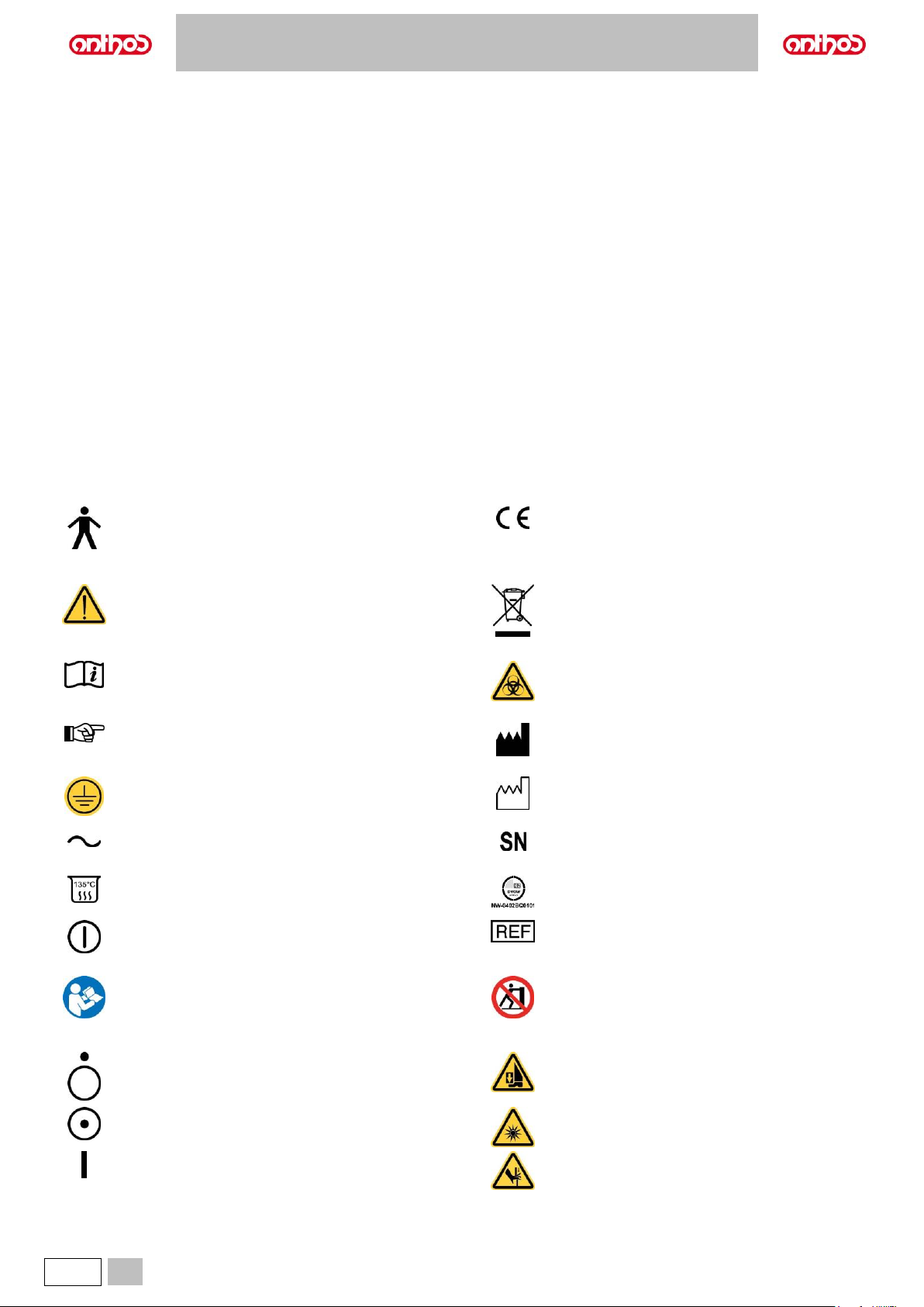
1.1. SYMBOLS
Note the meaning of the following symbols and expressions:
Type of protection against direct and indirect contact:
Class I.
Type of protection against direct and indirect contact:
Type B.
Accessory in compliance with essential requirements of
directive 93/42/EU and subsequent changes
(Class I Medical Device).
WARNING!
Failure to observe may result in equipment damage or
injury to the user and/or patient.
Disposal symbol in accordance with Directive
2012/19/EU.
"Consult the instruction manual"
It means that it is advisable to consult the instruction
manual before using that part of the device.
“Warning biological hazard”.
It provides information about possible risks of
contamination deriving from contact with fluids, storage of
infected biological waste.
NOTE:
Identifies information that is especially important for the
user and/or the assistant.
Manufacturer.
Protective ground contact.
Equipment date of manufacture.
Alternating current.
Device serial number.
Part that can be sterilized in a steam autoclave up to 135°
C.
DVGW compliance mark.
ON / OFF button.
Product/equipment identification code.
"Refer to the instruction manual"
Means that for reasons of safety you need to consult the
instruction manual before using the equipment.
Pushing prohibited.
Off (a part of the unit).
Foot crushing hazard.
On (a part of the unit).
Equipment equivalent to Class 2 light source.
Equipment On.
Hand crushing hazard.
Page 5
A5 - A6 PLUS - L6
EN
5
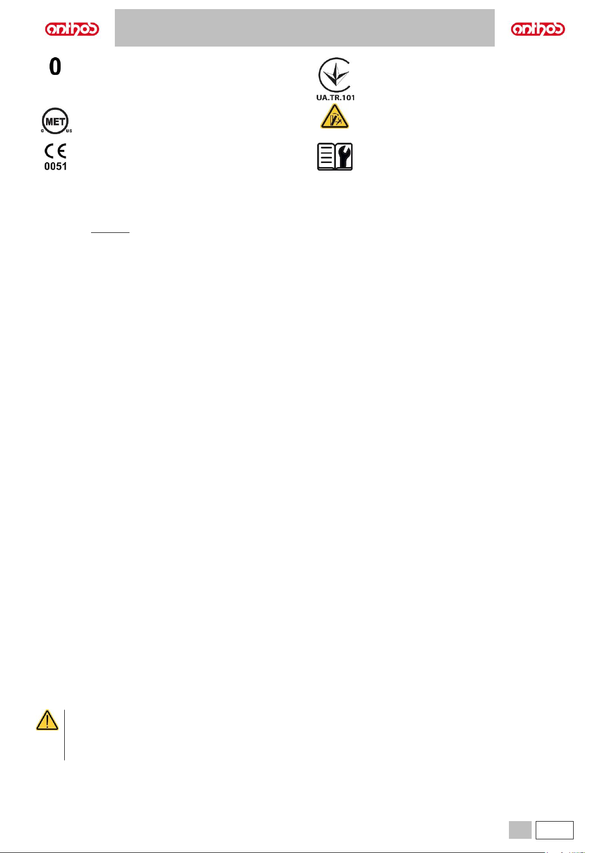
Equipment OFF.
Ukrainian national symbol of conformity.
C(MET)us Quality Mark (USA and CANADA)
Tipping hazard.
Equipment in compliance with essential requirements of
directive 93/42/EU and subsequent changes
(Class IIa Medical Device).
Notified body: IMQ spa.
"Refer to the Technical Manual"
It means that for reasons of safety you need to consult
the Technical Manual before using the equipment.
1.2. INTENDED USE
The device is a dental unit consisting of components and/or devices that are functionally connected, such as the patient chair, dental unit, dental
handpieces, multifunction pedal and operating light.
The dental unit is intended for professional dental treatment, for example to treat oral and dental pathologies of varying degrees of clinical form, stage,
gravity; and to manage and provide support for dental and oral diagnosis, treatments, post-operative controls for oral health, prevention and prophylaxis.
The prevailing medical conditions to be treated with the dental unit belong to the following branches of dentistry and oral health:
• Oral Hygiene;
• Orthodontics;
• Conservative dentistry and Prosthesis;
• Periodontology;
• Endodontics;
• Implants;
• Oral Surgery.
In order to achieve its intended use, the dental unit may support and control the following parts or devices, if supplied:
• Air/water syringe;
• Turbine;
• Micromotor;
• Scaler;
• Ultrasonic surgical equipment;
• Curing Light;
• Intraoral camera;
• Intraoral X-ray sensor;
• Intraoral 3D Scanner;
• Operating Light;
• Suction system;
• Multimedia systems;
• Intraoral X-ray equipment (support only, excluding management)
The dental chair is designed to support and position the patient during dental treatment.
Contraindications
The device is not intended for the following uses and/or applications:
- Use on unintended anatomical areas;
- Use on patients weighing more than the maximum permitted load;
- Use on non-alert or uncooperative patients or patients unable to maintain their position for the duration of the operation;
- Use by an unauthorised dental practitioner;
- Use by an operator not trained on the device.
Characteristics of the dental unit
• The dental units described in this manual are Medical Devices intended for dental treatment.
• The dentist's board may hold up to 6 instruments.
• The assistant’s board can hold 2 suction tubes and 3 instruments.
• This equipment must be used only by adequately trained personnel (dentists and paramedics).
• The device is intended for non-continuous operation with intermittent loads (see the operating times of the individual parts in the dedicated sections).
• The device is classified as pollution degree 2 (under IEC 60601-1).
• Overvoltage category (under IEC 60664-1): II.
(for American and Canadian markets only):
Dental units and relevant accessories are intended for dental treatment and provide the dentist with a user interface allowing to control the
operation of dental chair and all connected instruments. The system supplies air, water, a suction system and electricity to allow the dentist to
intuitively control all the procedures for patient care normally performed in a dental surgery.
Federal law restricts the sale of this equipment to dentists only.
Page 6
A5 - A6 PLUS - L6
6
EN
1.2.1. CLASSIFICATION AND REFERENCE STANDARDS
• Classification of MEDICAL DEVICES:
Classification of the dental unit in accordance with the indications given in annex IX of directive 93/42/EC as amended and supplemented: Class IIa.
• Classification of ELECTRICAL MEDICAL EQUIPMENT:
Classification of the dental unit in accordance with standard EN 60601-1 on safety of medical equipment: Class I - Type B.
• Reference standards:
the dental units described in this manual are designed in compliance with IEC 60601-1:2005 + CORR.1 (2006) + CORR.2 (2007) (Ed.3), IEC 60601-16:2010 (Ed.3), IEC 62366:2007 (Ed.1), IEC 80601-2-60:2012 (Ed.1), IEC 60601-1-2:2014 (Ed.4), IEC 62304:2006 (Ed.1), ISO 6875:2011 (Ed.3), ISO
7494-1:2011 (Ed.2) and EN 1717:2000 (Ed.1) standards on devices for the safety of the water system (protection unit type AA and AB).
1.2.2. ENVIRONMENTAL CONDITIONS
The equipment is to be installed in rooms that satisfy the following requirements:
• temperature between 10 and 40 °C;
• relative humidity between 30 and 75%;
• atmospheric pressure ranging from 700 to 1060 hPa;
• altitude ≤ 3000 m;
• air pressure entering equipment ranging from 6 to 8 bar;
• water hardness at the equipment inlet must not be above 25 °f (French degrees) or 14 °d (German degrees) for untreated drinking water. For water with
a higher hardness degree, it is recommended to soften water until it reaches a hardness degree between 15 and 25 °f (French degrees) or between 8.4
and 14 °d (German degrees);
• water pressure entering equipment ranging from 3 to 5 bar;
• water temperature entering equipment not higher than 25 °C.
1.2.2.1. STORAGE CONDITIONS
• Temperature between -10 and 70°C;
• Relative humidity between 10 and 90%;
• Atmospheric pressure: from 500 to 1060hPa.
1.2.3. WARRANTY
CEFLA s.c. stands behind its products warranting safety, reliability and performance.
The warranty is valid only under the following terms:
• Conditions given on the warranty certificate are observed.
• Yearly scheduled maintenance is performed.
• The equipment is used only as instructed in this manual.
• The electric system in the room in which the equipment is installed must conform to IEC 60364-7-710 (standards for electric systems in medical and
dental offices).
• A 3x1.5 mm2 line protected by a bi-polar cut-out that conforms to applicable standards (10 A, 250 V, distance between contacts at least 3 mm) must be
used to feed the equipment.
The colour of the three wires (POWER, NEUTRAL and EARTH) should satisfy the requirements of current standards.
• Installation, repairs, equipment enlargement, settings and, in general, any other operation requiring the casing to be opened are to be performed
exclusively by personnel authorised by CEFLA s.c..
1.2.4. DISPOSING THE EQUIPMENT WHEN NO LONGER USED
In compliance with Directives 2011/65/EU and 2012/19/EU regarding restriction of the use of certain hazardous substances in electrical and electronic
equipment along with waste electrical and electronic equipment, it is forbidden to dispose of this equipment in the municipal waste stream as unsorted
municipal waste.
When purchasing a new device of an equivalent type, one for one, the device that has come to the end of its lifetime should be returned to the dealer for
disposal. As regards reuse, recycling and other forms of recovery of waste electrical and electronic equipment, the Manufacturer carries out the functions
defined by current local laws. Appropriate differentiated waste collection for subsequent recycling treatment and environmentally friendly disposal
contributes to preventing possible negative effects on the environment and health and encourages recycling of the materials of which the device is made
up. The symbol indicating separate collection for electrical and electronic equipment consists of the crossed out bin marked on the equipment.
Under local legislation, fines can be imposed if the equipment is disposed in an illegal manner.
Page 7
A5 - A6 PLUS - L6
EN
7
1.3. SAFETY WARNINGS
• All equipment is permanently installed.
Depending on the type of dental chair the dental unit comes with, refer to the installation SCHEMATICS in paragraph TECHNICAL
SPECIFICATIONS.
The CEFLA s.c. shall not be held liable for any personal injury or property damage arising from failure to heed the following clause.
• Floor conditions.
The floor (continuous) should meet the load-bearing capacity set forth by DIN 1055, sheet 3.
The dental unit weighs approximately 400 kg, including the maximum load of 190 kg permitted on the dental chair.
For further details on anchoring conditions, refer to the Installation Manual.
The positions of delivery and drain line connections comply with standard ISO 7494-2.
In case of floor installation without load distribution plate, floor characteristics must ensure a breaking strength of the anchor bolt not less
than 1200 daN each (considering RcK concrete strength 20 MPa). In case of floor installation with load reduction plate, floor characteristics
must ensure a strength of the anchor bolt not less than 260 daN.
• This device may not be modified in any way without the authorisation of the manufacturer.
If the device is modified, appropriate examinations and tests need to be conducted in order to ensure continued safe use.
The CEFLA s.c. shall not be held liable for any personal injury or property damage arising from failure to heed the following clause.
• Dental chair.
The maximum load values indicated in the TECHNICAL SPECIFICATIONS paragraph must never be exceeded.
• Tray holders.
The maximum weights that can be held must never be exceeded:
- tray holder attached to the dentist's board, maximum permitted load on the tray holder module 2 kg, evenly distributed.
- tray holder attached to the assistant's board, maximum permitted load 1 Kg, evenly distributed.
- auxiliary tray holder, maximum permitted load on the tray 3.5 Kg (without negatoscope) or 2.5 Kg (with negatoscope).
• Connections to external instruments.
The equipment can be electrically connected only to other instruments that bear the CE mark.
• Electromagnetic interferences.
Use of electrical equipment that does not comply with standard IEC 60601-1-2 in the office or nearby may cause electromagnetic or other
types of interferences resulting in dental unit malfunctions.
In these cases, it is recommended to shut off power to the dental unit before using this equipment.
• Replacing the drills.
Operate the turbine release and contra angle devices only once the drill has come to a complete stop. Failure to do so will result in damaging
the locking system and drills could be released and cause injury. Exclusively use high-quality drills with a connection rod having a calibrated
diameter. To check the conditions of the locking system, make sure the drill is firmly secured to the instrument every day before starting
work. Locking system defects caused by misuse can be easily identified and are not covered by the warranty.
The drills and various instruments attached to the handpieces must comply with Biocompatibility Standard ISO 10993.
• Patients with active implantable medical devices.
When treating patients with implanted active devices, such as cardio-stimulators, hearing aids or other active devices, the possible effects
of the instruments used on the implanted device should be considered. Please refer to the technical-scientific literature available on this
subject and to the instructions for use of said devices.
• Use with external instruments.
If the dental unit is used for operations using separate standalone equipment such as mobile equipment for implants or endodontics, you
are recommended to power off the dental chair to avoid unwanted movements resulting from accidental start up of the movement controls.
• Do not forget to turn off the office water supply and main switch on the equipment before leaving the surgery.
• The equipment is not protected against liquid penetration IP X0.
• The equipment is not suitable for use in the presence of a mixture of flammable anaesthetic gas with oxygen or nitrous oxide.
• This equipment must be stored properly so that it is kept in top working order at all times. The manufacturer shall not be held responsible
(under civil and criminal law) for misuse, carelessness or improper use of the equipment.
• The equipment may only be used by authorised and adequately trained staff (dentists and paramedics).
• The user must be present at all times when the equipment is turned on or ready for start-up. In particular, never leave the equipment
unattended in the presence of minors/incapacitated subjects or other unauthorised personnel in general.
Any accompanying person must stay outside the area in which the treatment is performed and in any case on responsibility of the operator.
The operating area refers to the space around the dental unit plus 1.5 meters.
• Quality of the water delivered by the dental unit.
The user is responsible for the quality of the water delivered by the dental unit and must adopt measures to maintain the water quality.
To ensure that delivered water is kept to quality standards, CEFLA s.c. recommends equipping the dental unit with an internal or external
disinfection system.
The dental unit, once installed, is exposed to possible contaminants coming from the water mains. So, to effectively overcome this problem,
it is recommended to install and operate the dental unit only at the moment in which the professional will use it daily and perform the
disinfecting procedures starting from the day in which it is installed by following the instructions set forth in the relevant sections.
If the dental unit is equipped with the air separation device from water mains (EN 1717), make sure that the expected continuous supply of
disinfectant is also carried out by ensuring that the relevant tank contains a suitable quantity of disinfectant (see relevant paragraph).
Contact your local dealer or Association of Dentists for more detailed information about national laws and requirements.
Applied parts.
The parts that, during standard use, necessarily come into contact with the patient in order for the device to carry out its functions correctly,
are: dental chair upholstery, armrest, curing light fiber optic, terminal part of the syringe, single-use camera protection, scaler tips, handpiece
drills, suction tube holder terminals.
Non applied parts that may come into contact with the patient are: dental chair armrest support, dental chair lower casing, patient-side water
unit casing, water-to cup-spout, bowl, suction tubes, handpiece body.
Page 8
A5 - A6 PLUS - L6
8
EN
• Dental chair movement.
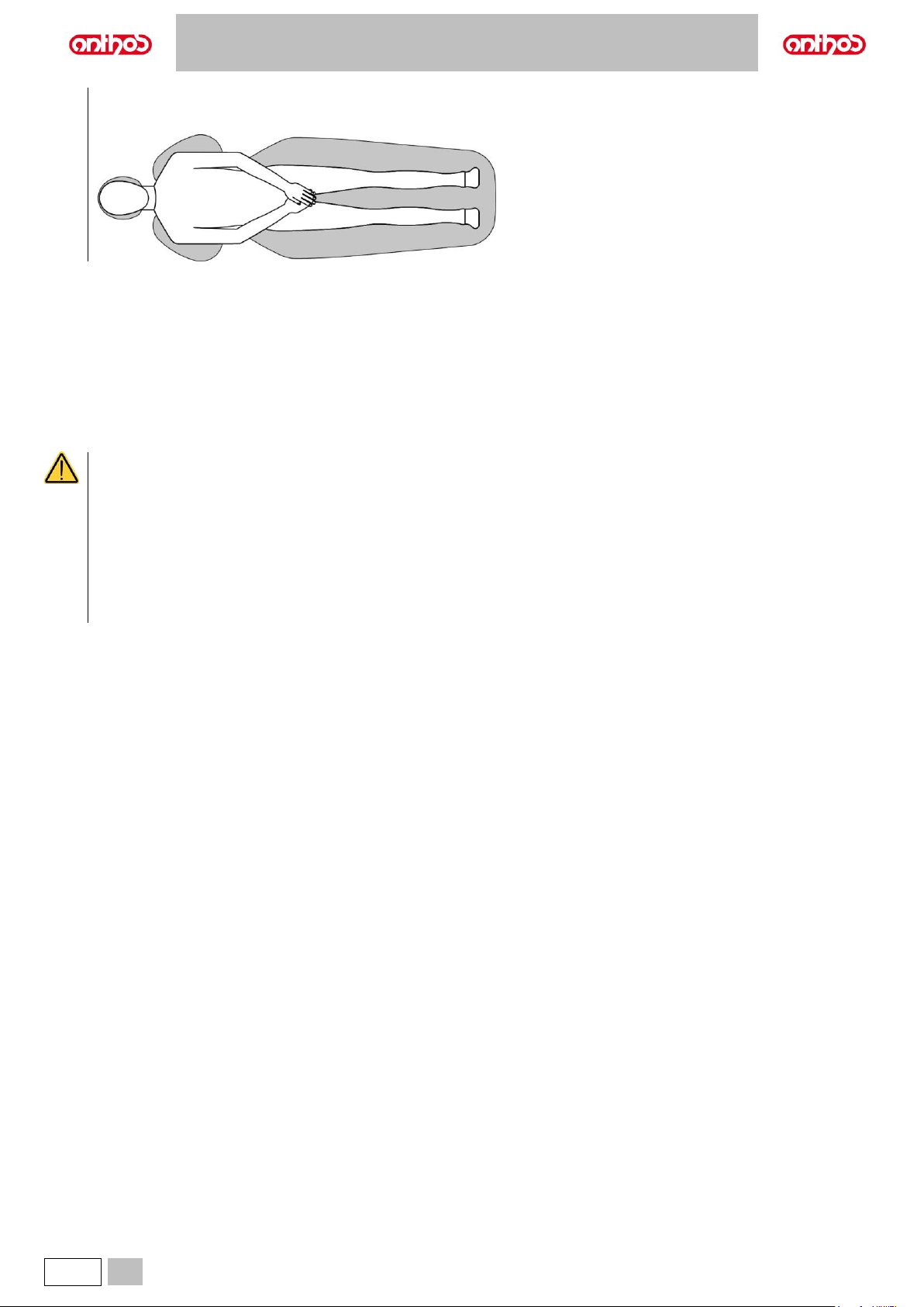
Make sure that the patient is ready to collaborate: ask him/her to keep his/her hands and feet close, avoiding incorrect postures.
Check that the patient is sitting properly when moving the chair (see figure).
1.4. ELECTROMAGNETIC SAFETY
Electromagnetic immunity.
The device is intended for use in environments recognised as professional health facilities, as described in IEC 60601-1-2:2014. The device belongs to
CISPR 11 Class A Group 1 and complies with immunity test levels specified by IEC 60601-1-2:2014 for professional health facilities.
Before using any electronic device in health facilities, always check that it is compatible with the other equipment present.
If it is used in a residential environment (as specified in CISPR 11 class B) this equipment might not offer adequate protection to radio-frequency
communication services. The user might need to take mitigation measures, such as relocating or re-orienting the equipment.
For further information on immunity levels and characteristics of the electromagnetic environment, see the specific tables in paragraph TECHNICAL
SPECIFICATIONS.
• Use of this equipment adjacent to or stacked with other equipment should be avoided, because it could result in improper operation.
If such use is necessary, this equipment and the other equipment should be observed to verify that they are operating normally.
• Use of accessories, transducers and cables other than those specified or provided by the manufacturer of this equipment could result
in increased electromagnetic emissions or decreased electromagnetic immunity of this equipment and result in improper operation.
• Portable RF communications equipment (including peripherals such as antenna cables and external antennas) should be used no
closer than 30 cm (12 inches) to any part of the device, including cables specified by the manufacturer.
Otherwise, degradation of the performance of this equipment could result.
• Do not subject the device to strong electromagnetic disturbances.
Electrical medical equipment are subject to special precautionary measures in relation to electromagnetic compatibility (EMC). The
equipment must be installed and used according to the Manufacturer’s instructions. Failure to observe the installation requirements
and the Manufacturer’s instructions could affect the equipment position and the correspondence of its operating parameters.
Page 9
A5 - A6 PLUS - L6
EN
9
1.5. CLEANING AND DISINFECTION
Cleaning is the first step required for any disinfection process.
Physically scrubbing with detergents and surface-active substances and rinsing with water removes a considerable amount of micro-organisms. If the
surface is not first cleaned, the disinfection process cannot be successful.
If a surface cannot be adequately cleaned, it should be protected with barriers.
The outer parts of the equipment must be cleaned and disinfected using a product for hospital use with indications for HIV, HBV and tuberculocidal
(medium-level disinfectant) specific for small surfaces.
The various drugs and chemical products used in dental surgeries may damage the painted surfaces and the plastic parts. Researches and tests performed
show that the surfaces cannot be fully protected against the harsh action of all products available on the market. We therefore recommend protecting with
barriers whenever possible.
The harsh actions of chemical products also depend on the amount of time they are left on the surfaces.
It is therefore important not to leave the product on the surfaces longer than the time specified by the manufacturer.
It is recommended to use the specific medium-level disinfectant, STER 1 PLUS (CEFLA s.c.), which is compatible with:
• Coated surfaces and plastic parts.
• Upholstery.
The MEMORY FOAM upholstery will stain when splashed with mordant acid. Immediately rinse with plenty of water if acid spatters
on the upholstery.
• Uncoated metal surfaces.
If you do not use STER 1 PLUS, it is recommended to use products that contain at maximum:
• Ethanol. Concentration: maximum 30 g per 100 g of disinfectant.
• 1-Propanol (n-propanol, propyl alcohol, n-propyl alcohol). Concentration: maximum 20 g per 100 g of disinfectant.
• Combination of ethanol and propanol. Concentration: the combination of the two should be maximum 40 g per 100 g of disinfectant.
• Do not use products containing isopropyl alcohol (2-propanol, iso-propanol).
• Do not use products containing sodium hypochlorite (bleach).
• Do not use cleaners containing phenols.
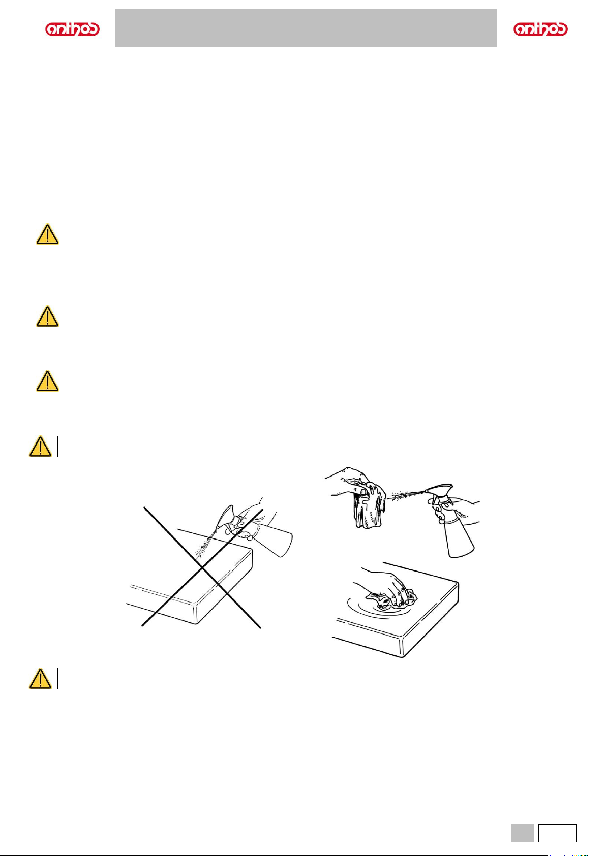
• Do not spray the selected product directly on the surfaces.
• All products must be used as directed by the manufacturer.
• Do not mix the STER 1 PLUS disinfectant with other products.
The products suggested are compatible with the materials of the equipment, however damages may occur to surfaces and materials
resulting from the use of different products, even if not included in the above list of excluded products.
Cleaning and disinfecting instructions.
Clean and disinfect with disposable non-abrasive paper (avoid using recycled paper) or sterile gauze.
Do not use sponges or, in any case, any material that can be reused.
• It is recommended to turn off the dental unit prior to cleaning and disinfecting the external parts.
• All material used to clean and disinfect must be thrown away upon completing the procedure.
The cleaning/disinfection/sterilization times of each element of the dental unit are listed in the booklet "PROTOCOL FOR HYGIENIC
MAINTENANCE OF THE DENTAL UNIT", also supplied with the unit.
Page 10
A5 - A6 PLUS - L6
10
EN
1.6. STERILISATION
Every instrument supplied is NOT STERILE and must be sterilised in steam autoclave (max. 135°C) before use, without performing any type of chemical
sterilization.
Sterilization must be performed using appropriate packaging materials, verified during the sterilization process validation.
It is recommended to sterilize in steam autoclave (moist heat) through a cycle with pre-vacuum (forced air removal).
Autoclaves must comply with and be approved and maintained in accordance with the requirements set forth by the Standards EN 13060 (or ANSI/AAMI
ST55), EN ISO 17665-1 and ANSI/AAMI ST79.
Below are the minimum recommended parameters for the sterilization of reusable medical devices, that have been approved in order to ensure a sterility
assurance level (SAL) equal to 10^-6:
• Cycle type: with pre-vacuum (Pre-vac).
• Method: "overkill" moist heat sterilization according to Standard ISO 17665-1.
• Minimum temperature: 134° C (273° F) for heat-resistant materials (instruments and metal handpieces, etc.);121°C (250°F) for thermolabile materials
(rubber items, etc.).
• Minimum exposure time (1): 4 minutes (at 134°C), 20 minutes (at 120°C).
• Minimum drying time (2): defined to ensure compliance with the requirements of Standard EN 13060 (or ANSI/AAMI ST55).
(1) Exposure time: time during which the load and the entire chamber are kept at a temperature higher than the sterilization one.
(2) Drying time: time during which steam is removed from the chamber and the chamber pressure decreases to allow the condensate to evaporate from
the load through a prolonged emptying or thanks to the supply of hot air or other gases then removed.
The drying time varies according to the load configuration and the packaging type and material.
2. DESCRIPTION OF THE EQUIPMENT
2.1. IDENTIFICATION PLATES
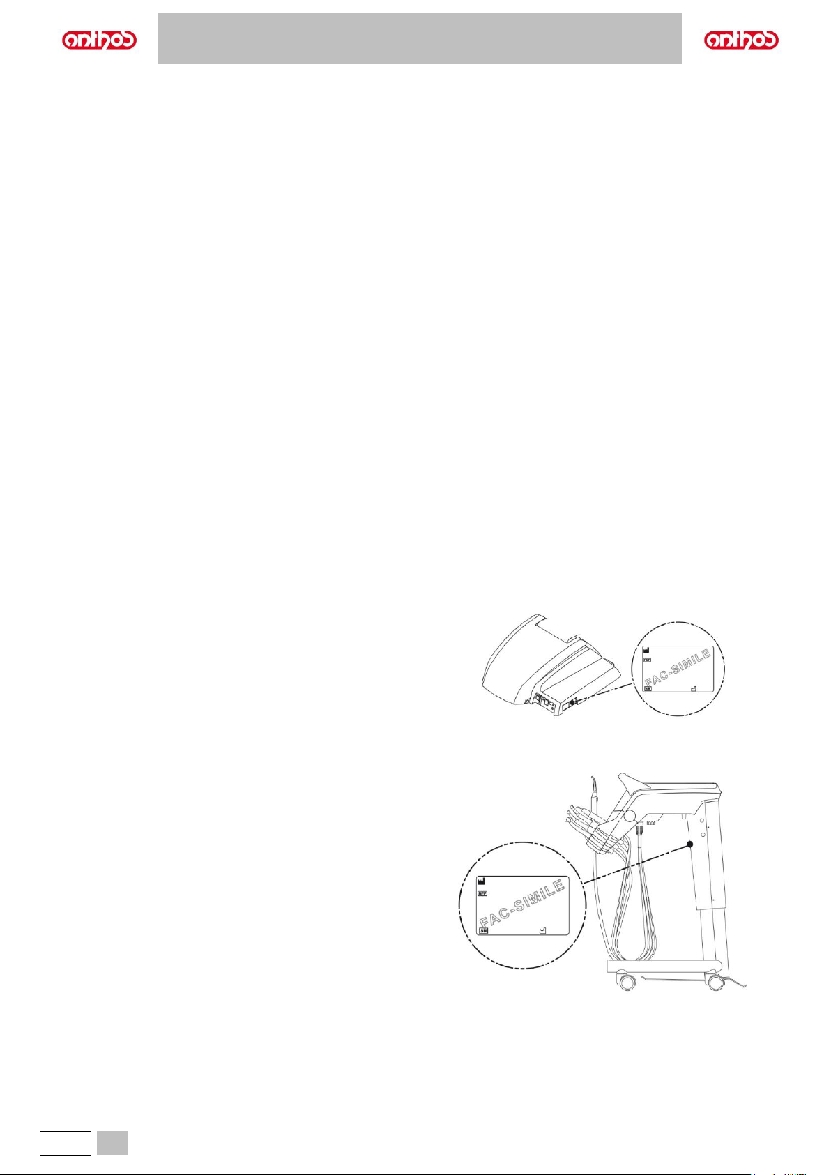
Data given on plate:
• Name of manufacturer.
• Name of equipment.
• Rated voltage.
• Type of current.
• Rated frequency.
• Maximum current or power absorbed.
• Serial number.
• Date of manufacture.
Nameplate position.
Dental units model:
A5 CONTINENTAL
A5 INTERNATIONAL
A5 SINGLE WATER UNIT
A6 PLUS CONTINENTAL
A6 PLUS INTERNATIONAL
A5 CART
Dental units model:
A5 SINGLE CART
Page 11
A5 - A6 PLUS - L6
EN
11
Dental units model:
L6 CONTINENTAL
L6 SIDE DELIVERY
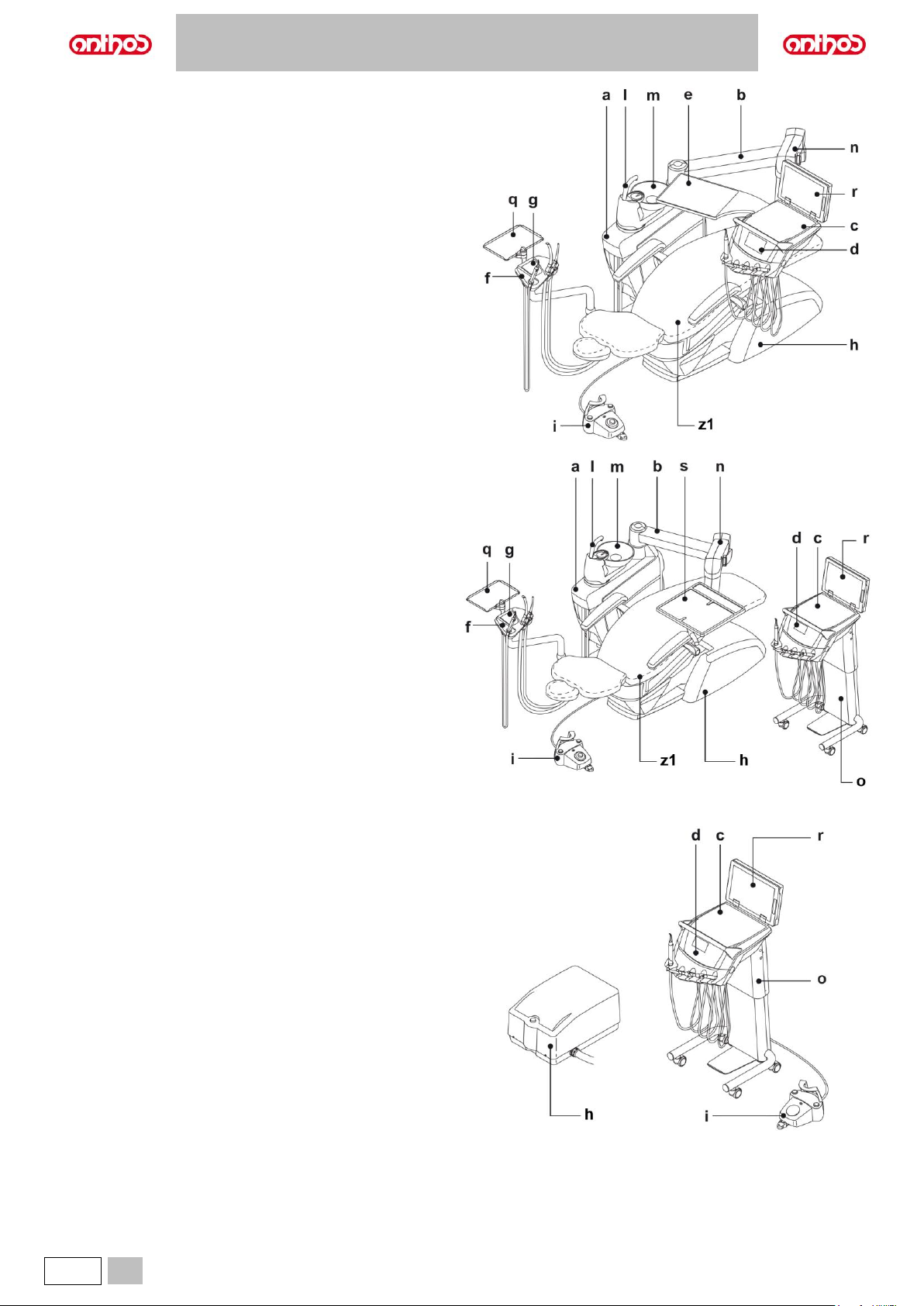
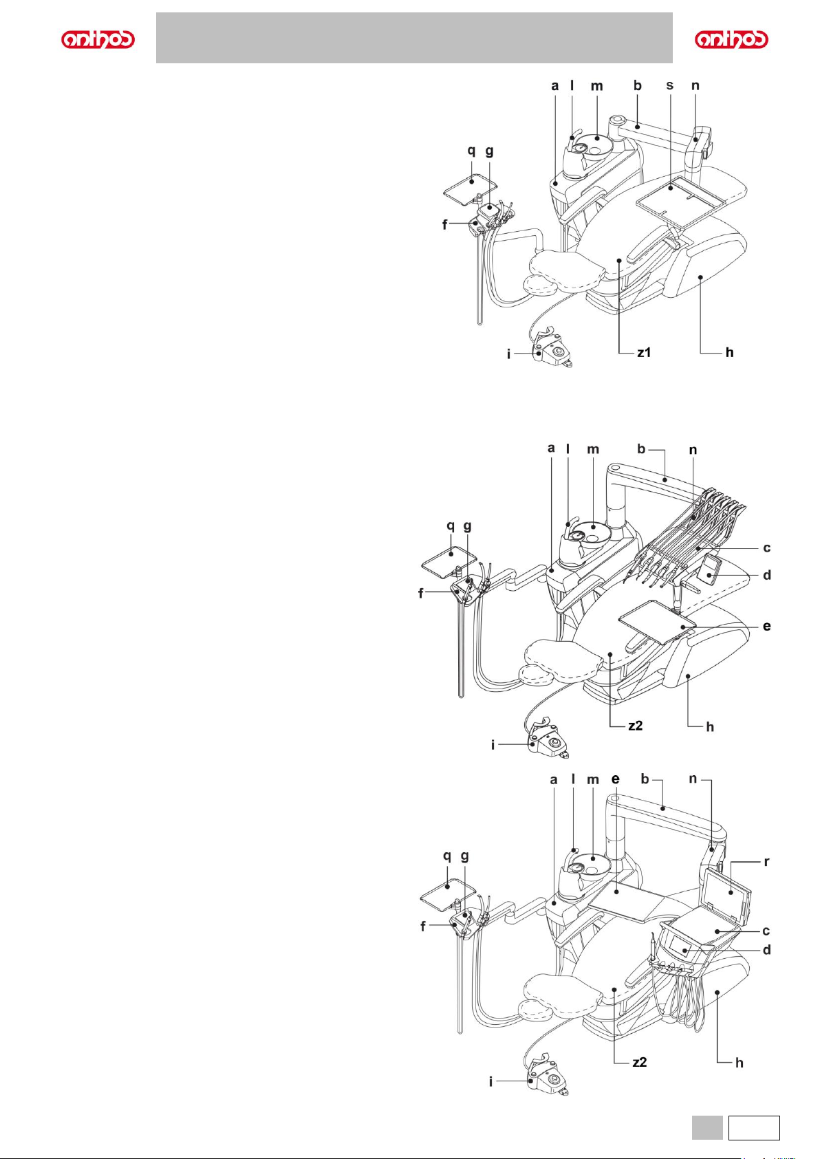
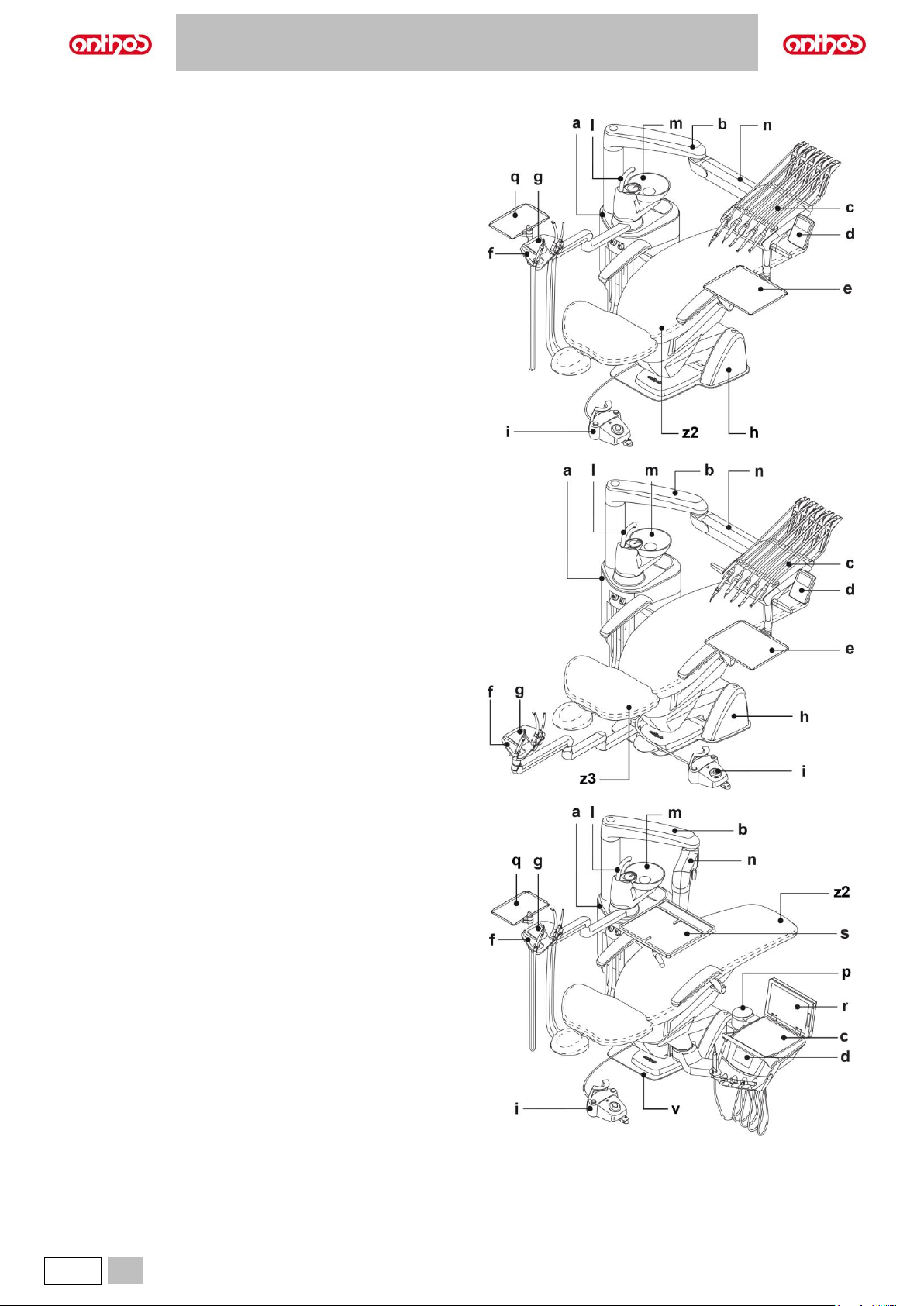
2.2. DENTAL UNITS
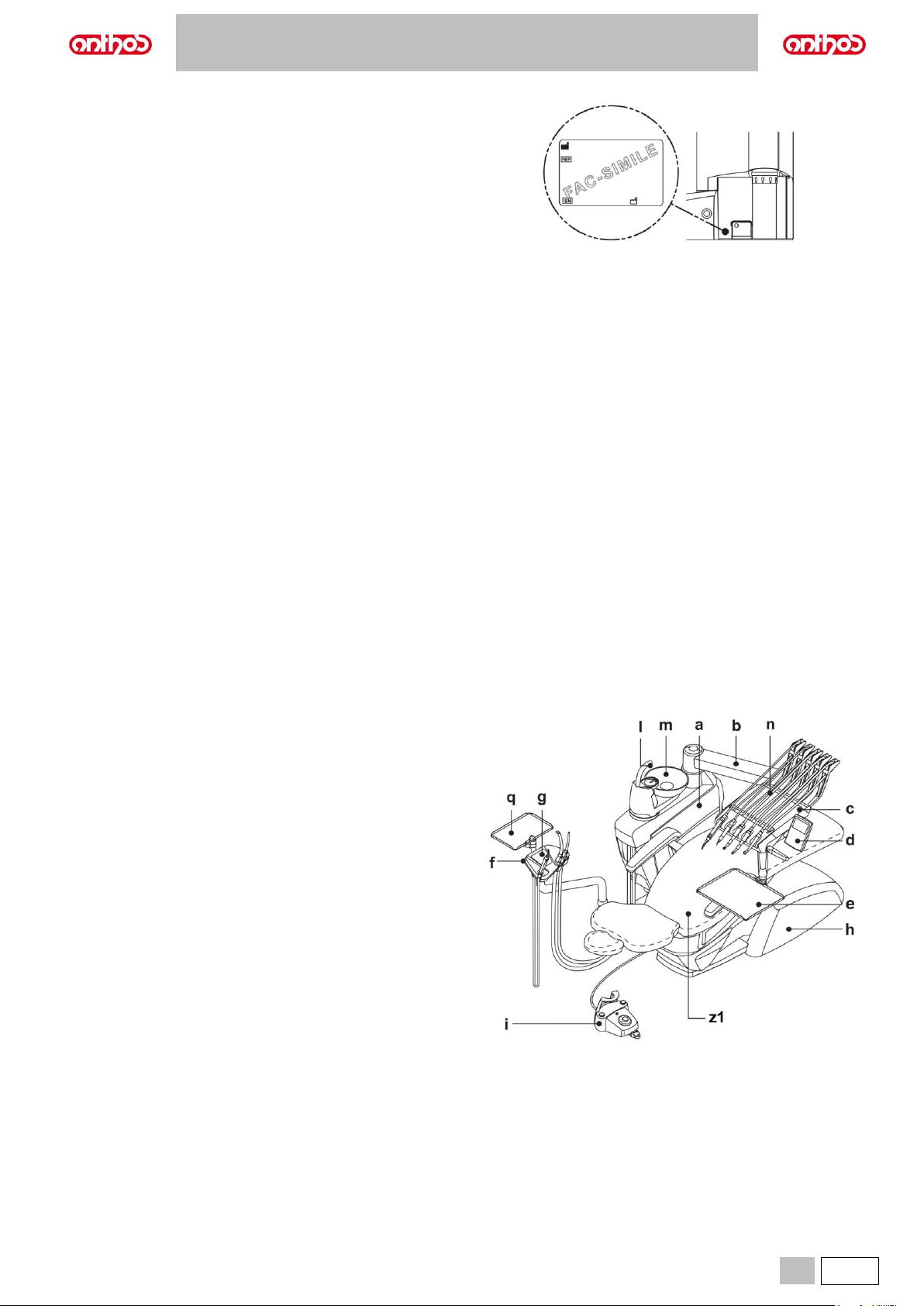
Description of the parts.
a Water unit.
b Adjustable arm.
c Dentist's board.
d Dentist’s control console.
e Tray holder (optional).
f Assistant’s board.
g Assistant’s board control console.
h Connection box.
i Multifunction foot control.
l Water-to-cup spout.
m Bowl.
n Self-balancing arm.
o Height-adjustable cart.
p Height-adjustable column
q Tray holder table on assistant's board (optional).
r Negatoscope for panoramic X-rays (optional).
s "PROFESSIONAL" auxiliary board (optional).
v Overturning protection plate (optional).
z1 ANTHOS A2.5 dental chair.
z2 ANTHOS A2.7 dental chair.
z3 ANTHOS A1.3 dental chair.
Model A5:
Model A5 CONTINENTAL (SN. 71HAxxxx)
Page 12
A5 - A6 PLUS - L6
12
EN
Model A5 INTERNATIONAL (SN. 71HBxxxx)
Model A5 CART (SN. 71HCxxxx)
Model A5 SINGLE CART (SN. 71HDxxxx)
Page 13
A5 - A6 PLUS - L6
EN
13
Model A5 SINGLE WATER UNIT (SN. 71HExxxx)
Model A6 PLUS:
Model A6 PLUS CONTINENTAL
Model A6 PLUS INTERNATIONAL (SN. 71HGxxxx)
Page 14
A5 - A6 PLUS - L6
14
EN
Model L6:
Model L6 CONTINENTAL (SN. 71HJxxxx)
Model L6 CONTINENTAL, HYBRID version (SN. 71HNxxxx)
Model L6 SIDE DELIVERY (SN. 71HKxxxx)
Page 15
A5 - A6 PLUS - L6
EN
15
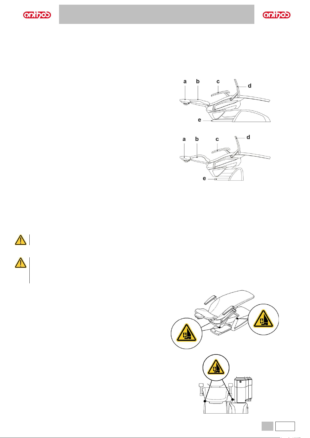
2.3. DENTAL CHAIR
Description of the parts.
a Headrest.
b Backrest.
c Fixed armrest.
d Removable armrest (optional).
e Stop foot board.
Dental chair of ANTHOS A2.5 and ANTHOS A2.7 model
Dental chair of ANTHOS A1.3 L model
Operating time.
The operating and rest times are as follows:
work 25 sec. - rest 10 min.
Maximum permitted load.
• Maximum permitted load on all other dental chairs: 190 kg.
• Maximum permitted load on headrest: 30 kg.
• Maximum load supported by armrest: 68 kg.
Do not exceed these values.
Warnings for use
CRUSHING HAZARD
• Despite the presence of safety systems to prevent crushing, there is always a minimum residual risk due to moving parts.
The positions already stored ensure a safety distance between dental chair and floor.
Do not store lower dental chair positions, and in any case pay attention to the risk of crushing.
• Pay attention to the patient and the staff during dental chair descent.
Dental units of A5 and A6 PLUS model
Dental units of L6 model
Page 16
A5 - A6 PLUS - L6
16
EN
2.4. SPECIAL WARNINGS
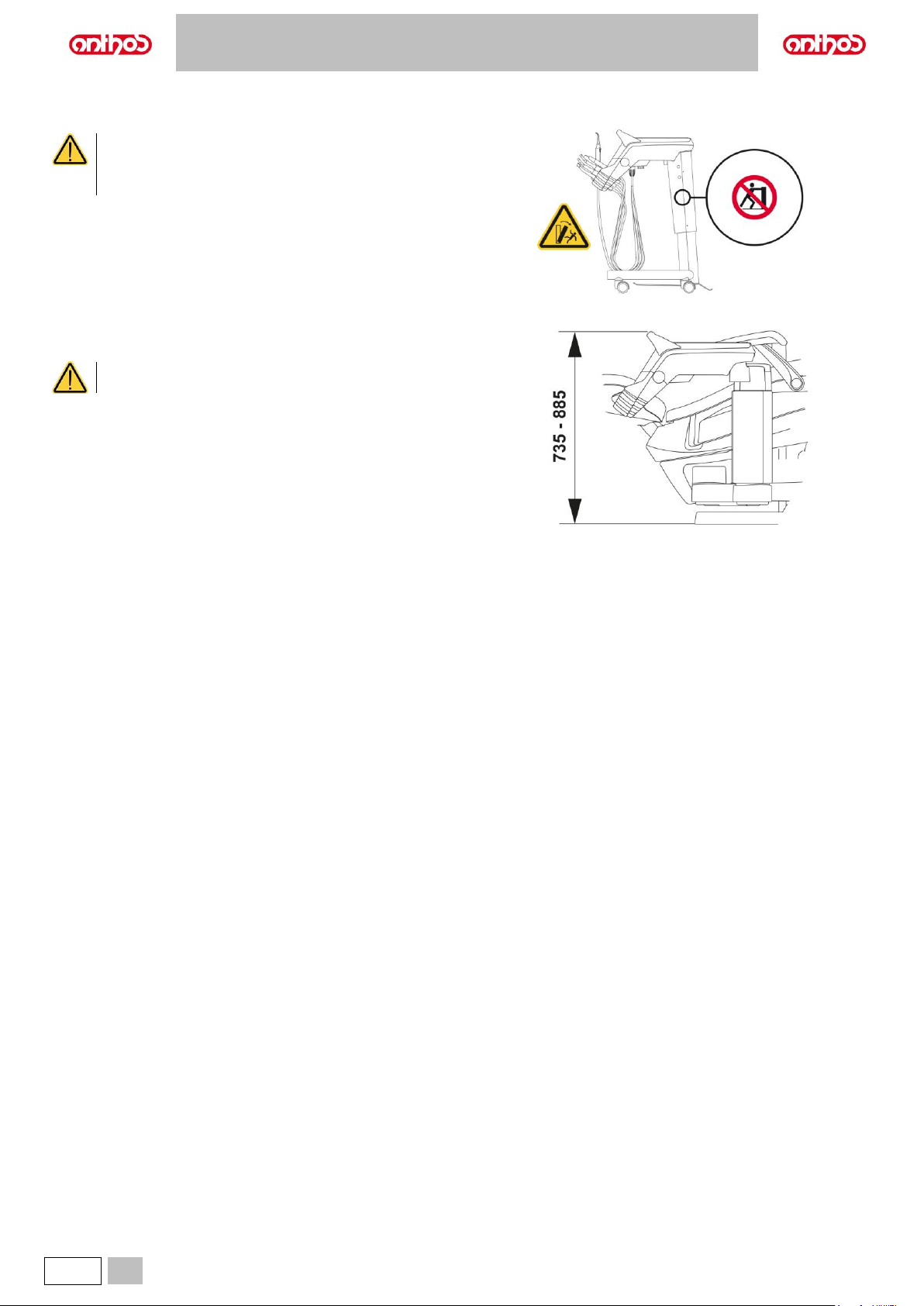
Models A5 CART and A5 SINGLE CART
TIPPING HAZARD
To move the cart, grab the relevant handle. When moving it,
take care to any step and/or horizontal obstacle as cart
could become unstable and/or even overturn.
Models L6 SIDE DELIVERY with fixed height board
During installation, the cart board can be adjusted in height to 7 predefined
working positions: min. height 735 mm, max. height 885 mm.
Board height adjustment must be carried out by a ANTHOS
authorised technician, only.
Page 17
A5 - A6 PLUS - L6
EN
17
3. STARTING
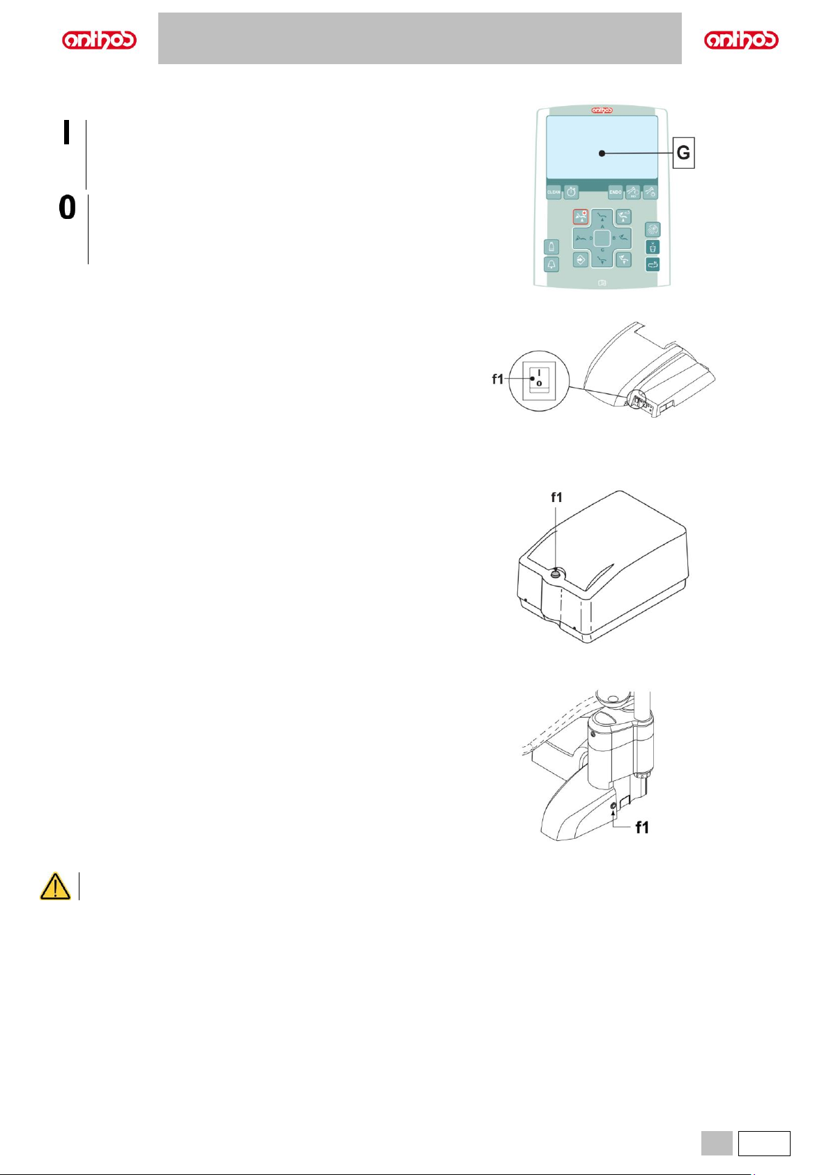
Press the main switch (f1)
Switch (f1) on:
- equipment ON;
- electric system powered;
- water and air system connected;
- DISPLAY (G) on.
Switch (f1) off:
- equipment OFF;
- electric system not powered;
- water and air system not connected;
- DISPLAY (G) off.
Dental units model:
A5 CONTINENTAL
A5 INTERNATIONAL
A5 CART
A5 SINGLE WATER UNIT
A6 PLUS CONTINENTAL
A6 PLUS INTERNATIONAL
Dental units model:
A5 SINGLE CART
Dental units model:
L6 CONTINENTAL
L6 SIDE DELIVERY
Main switch must be pressed with your hands.
Page 18
A5 - A6 PLUS - L6
18
EN
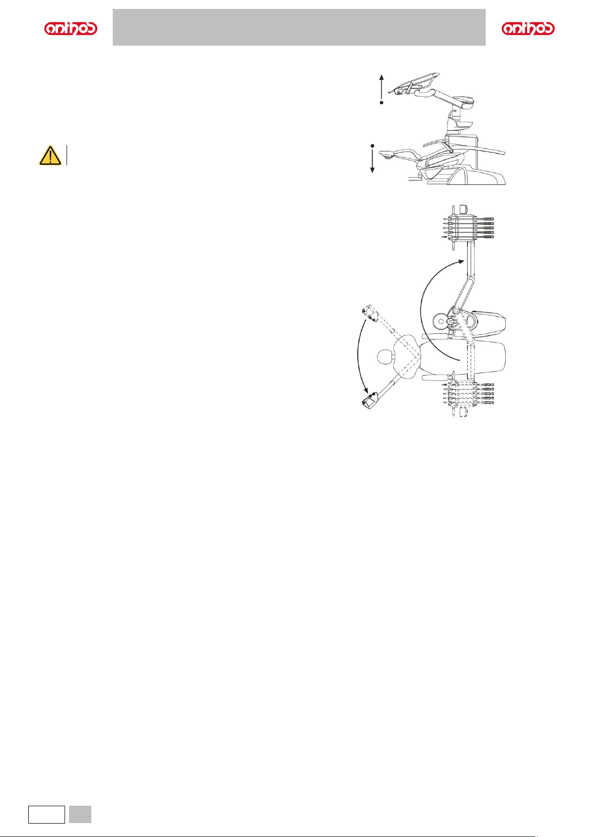
3.1. CONVERSION OF THE DENTAL UNIT CONFIGURATION FOR LEFT-HANDED OPERATORS (HYBRID version only)
To reverse dental unit configuration, proceed as follows:
• Lower the dental chair and the backrest until the headrest is lower than
the water unit.
• Lift the dentist’s board up to its highest position.
• Turn the dentist’s board arm over the dental chair to reach the outer
side of the water unit and continue turning until reaching the end of
travel.
During this rotation, be careful to avoid any collision with
the water-to-cup spout.
• Move the dentist’s board arm back to the required position and place
the pantograph arm and the board in the optimal work positions.
• Now lift the backrest and move the assistant's board from the water unit
side to the opposite side, aiming it in the required direction.
• Finally, reverse the dentist’s board console position (see paragraph 5.).
To set the machine back to a configuration suitable for right-handed
people, repeat the indications from the first point, but reversing the
rotations of arms.
Page 19
A5 - A6 PLUS - L6
EN
19
4. DENTAL CHAIR OPERATION
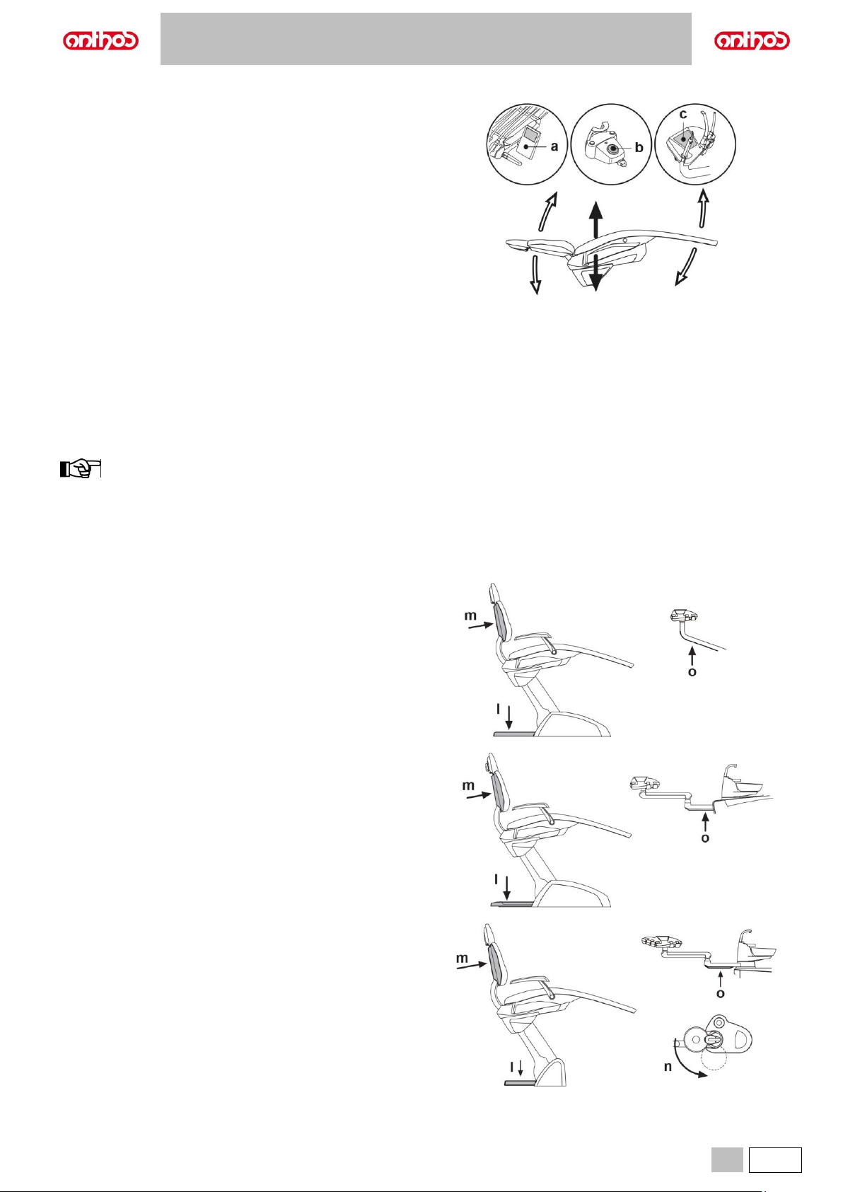
Dental chair movements.
The dental chair can be operated from the following units:
• Dentist's board (a) (see par. 5.).
• Multifunction foot control (b) (see par. 5.2.).
• Assistant’s board (c) (see par. 6.).
Dental chair movements:
• Seat up/down.
• Backrest up/down with inclination of the seat (compensated
Trendelenburg).
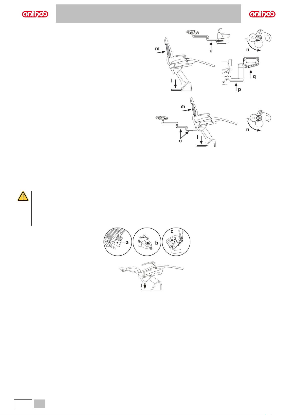
4.1. SAFETY DEVICES
Dental units are equipped with safety devices that, in the presence of an obstacle, immediately stop the dental chair’s movements.
Description of safety devices.
l Stop foot board: when pressed, it immediately stops dental chair from moving down and automatically lifts it up to free the obstacle.
m Dental chair’s backrest: it immediately stops dental chair from moving down in the presence of an obstacle and automatically lifts it up to free the
obstacle.
n Bowl: when the bowl is manual and located in the interference area, the dental chair up movement is stopped at the maximum permitted height.
With motor-driven bowl, the safety device automatically moves the bowl out of the interference area with the dental chair.
o Assistant's board arms: the dental chair is immediately stopped from moving down in the presence of an obstacle and automatically lifted up to free
the obstacle.
p SIDE DELIVERY board arm: the dental chair is immediately stopped from moving down in the presence of an obstacle and automatically lifted up to
free the obstacle.
q SIDE DELIVERY board: the dental chair/board is immediately stopped from moving down in the presence of an obstacle and (in the case of dental
chair) automatically lifted up to free the obstacle.
Dental units model:
A5 CONTINENTAL
A5 INTERNATIONAL
A5 CART
A5 SINGLE CART
A5 SINGLE WATER UNIT
Dental units model:
A6 PLUS CONTINENTAL
A6 PLUS INTERNATIONAL
Dental units model:
L6 CONTINENTAL
Page 20
A5 - A6 PLUS - L6
20
EN
Dental units model:
L6 SIDE DELIVERY
Dental units model:
L6 CONTINENTAL, HYBRID version
Dental chair movements:
- with the instrument extracted NOT working: manual movements allowed, automatic movements inhibited, but if they are already in progress at the
moment of extraction they are not interrupted;
- with instrument extracted and working: all the dental chair movements are inhibited.
4.2. MOVEMENT LOCK DEVICES
Use the devices below when movement of the equipment needs to be blocked:
• Dental chair control buttons (a) or (c).
By pressing any of the dental chair control buttons all movements will be stopped.
• Foot control (b).
When the foot control is actuated, all movements of the equipment are blocked.
• Stop foot board (i).
When the floor board is actuated, all movements of the equipment susceptible to cause squashing are blocked.
Page 21
A5 - A6 PLUS - L6
EN
21
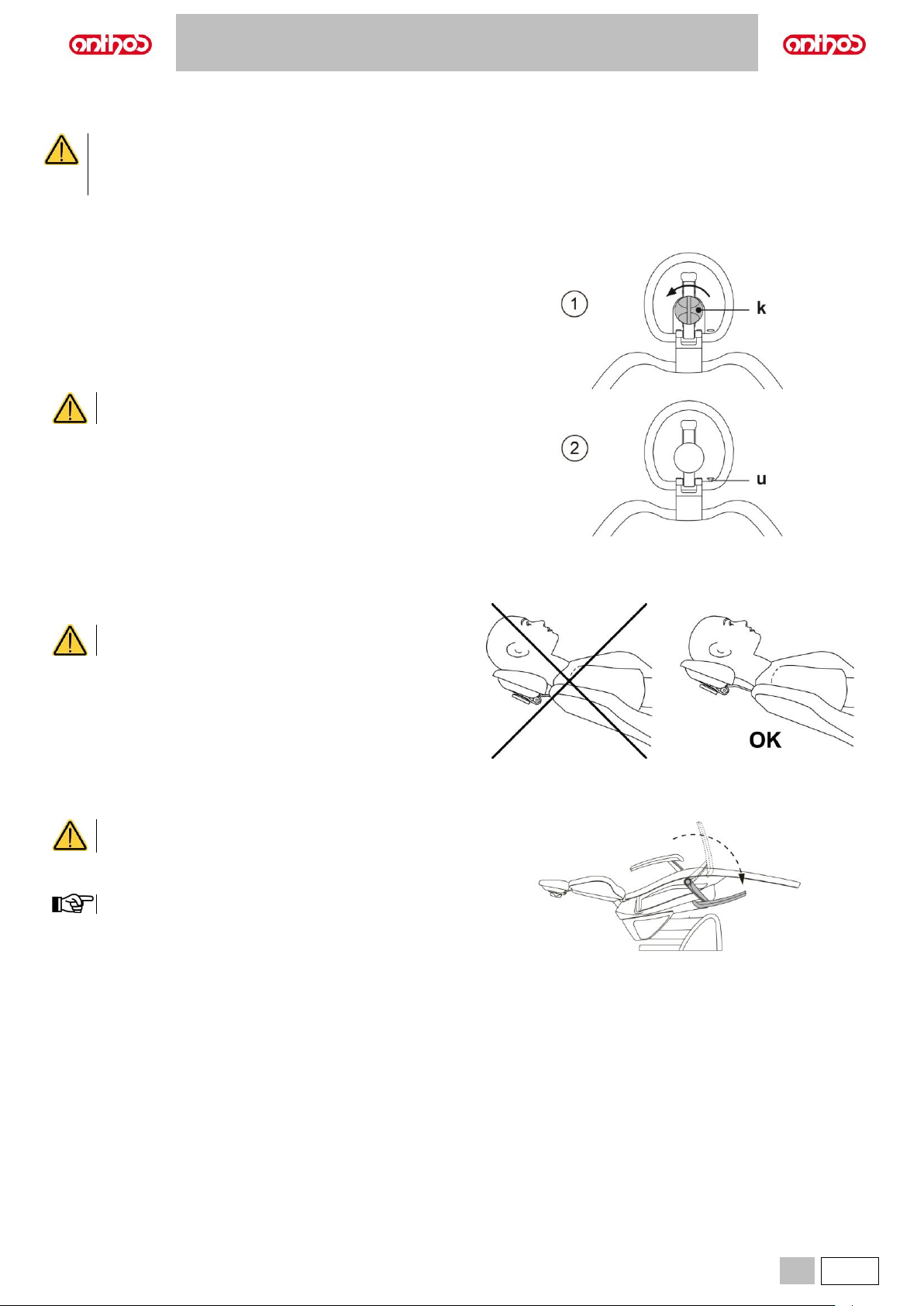
4.3. ADJUSTABLE HEADREST
Warnings for use.
• Maximum permitted load on headrest: 30 kg.
• Do not attempt to move headrest while patient is resting against it.
• Do not attempt to modify the position of the cushion without first releasing the lock mechanism.
• The pneumatic locking device is active only when the air circuit is pressurised and the dental unit is on.
Headrest models
Available models are:
1 with manual cushion retainer
2 with air-operated cushion retainer
Adjusting the manual headrest
• Lift or lower the headrest to the desired position.
• Unlock the cushion by turning the lock knob (k) counter-clockwise.
• Aim the cushion as desired.
• Lock the cushion again by turning the knob (k) clockwise.
Adjusting the air-operated headrest
Only when the dental unit is on.
• Raise or lower the headrest while holding down button (u).
• Aim the cushion as desired while holding down button (u).
Proper positioning of the headrest.
For correct use of the headrest, position the patient's head
as shown in the figure.
4.4. MOVABLE ARMRESTS (OPTIONAL)
Maximum load supported by armrest:
68 kg.
Turn movable armrest clockwise to move it downwards, so that the patient
can easily get on and off the chair.
Armrests cannot be extracted from the seat.
Page 22
A5 - A6 PLUS - L6
22
EN
5. DENTIST'S BOARD OPERATION
Layout of instruments.
The positions of the instruments on the board are determined by the customer at the time of order.
Enabling the instruments.
• Syringe is always on (see paragraph 5.3.).
• The curing light is turned on by the relevant button, when the instrument is extracted (see paragraph 5.7.).
• Intraoral camera turns on when the instrument is extracted (see paragraph 5.8.).
• ZEN-Xi integrated sensor is started by turning its support to the “ACTIVE” position (see paragraph 5.9 and ZEN-Xi instructions for use).
• Once picked up, all the instruments are operated with the foot control (see paragraph 5.2.).
Simultaneous use of the instruments.
An interlocking device ensures that the instruments are not used simultaneously.
The first extracted instrument is ready to be used while those extracted later are disabled by the interlocking device.
This interlocking device allows the drill to be changed in one instrument while another is used on the patient.
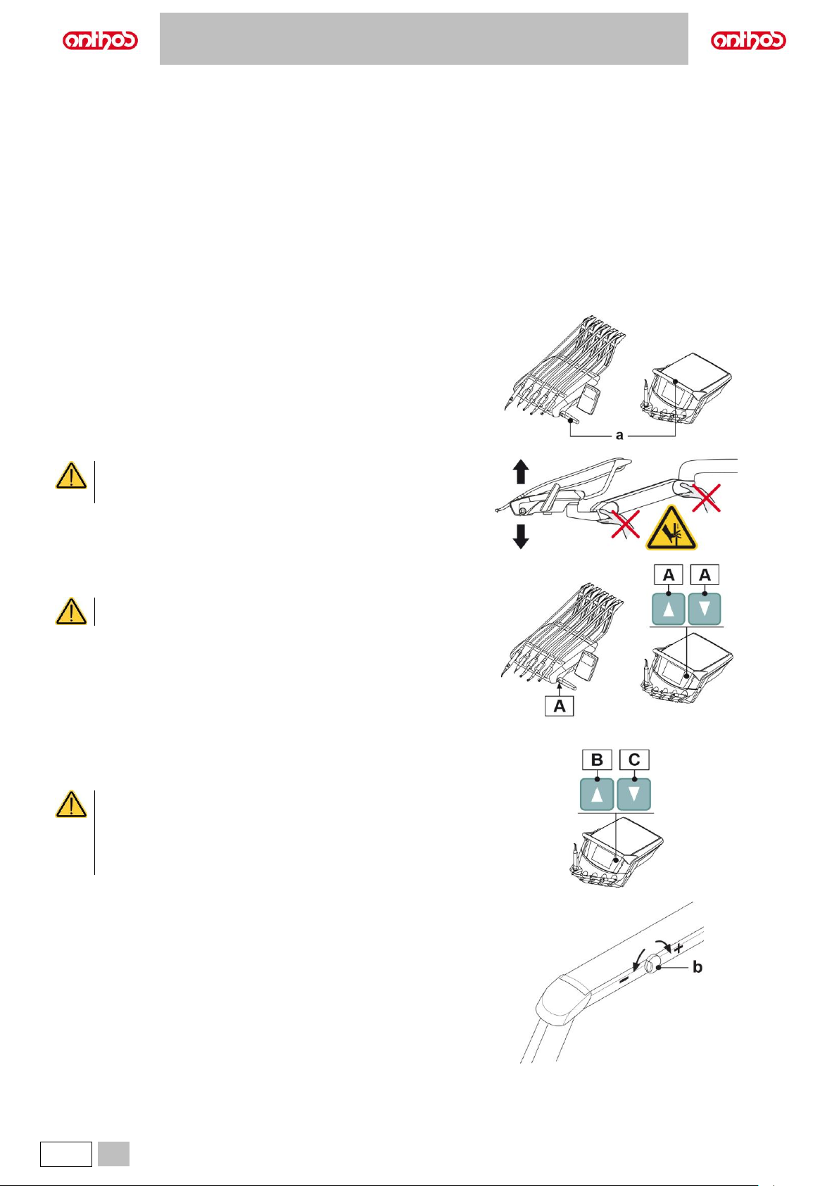
Positioning the dentist's board.
a Handle to adjust the height of the board and/or position it horizontally.
CRUSHING HAZARD
Do not grasp the arm junctions during dentist’s board
movements.
Models with pantograph arm with pneumatic brake.
A Board pantograph arm brake release button.
The release button is only active when the dental unit is
turned on.
Models with SIDE DELIVERY height-adjustable board
To adjust dentist's board height, press the special up (B) and down (C)
buttons.
• Up/down operating times for SIDE DELIVERY board:
continuous operation max. 2 min. - rest 18 min.
• SIDE DELIVERY version board: make sure that the board or
the ends of handpieces are not positioned over the backrest
during the dental chair’s automatic movements, since
upholstery may tear.
Pantograph arm with manual brake adjustment
Balancing of the pantograph arm is determined at the time of installation.
Any future adjustments can be made using the knob (b) on the pantograph
arm.
Clockwise rotation: to increase clutch resistance of the pantograph arm.
Counter-clockwise rotation: to decrease clutch resistance of the pantograph
arm.
Page 23
A5 - A6 PLUS - L6
EN
23
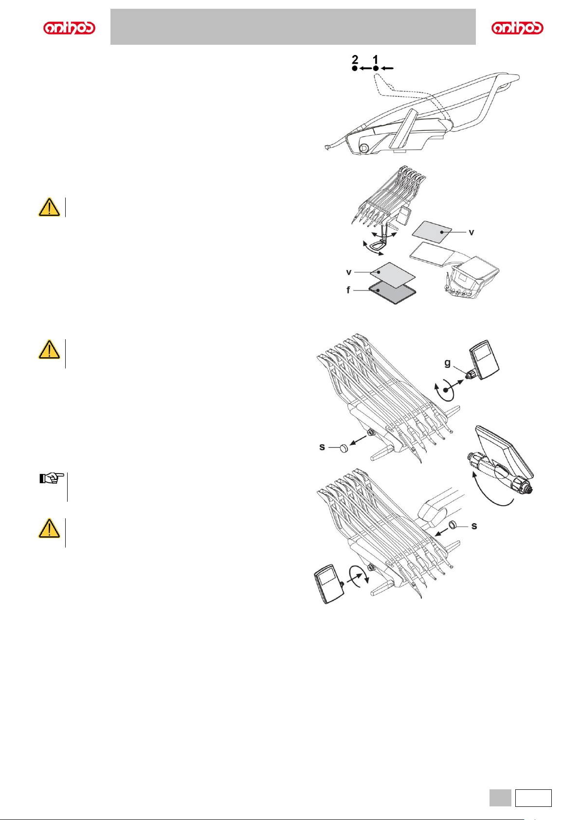
Instrument recall arm lock device (only version with upper recovery
of hoses).
The arm can be locked in the instrument extracted position, by taking it at
2/3 from the limit stop (1).
To go back to the original condition, move the arm to the end of its travel
(2).
Tray holder.
f Stainless steel tray holder that can be separated from its support.
v Silicone protection that can be sterilized in an autoclave at up to 135°C.
Maximum permitted load on the tray holder: 2 kg
distributed.
Console unit position reversal (with reversible console, only).
To reverse console unit position on dentist's board, proceed as follows:
• Remove the console unit after having loosened the relevant ring nut (g) by
turning it counter-clockwise.
• Remove the click-on cap (s) protecting the quick coupling on the left-hand
side, and insert it inside the one on the right-hand side.
• Turn console unit supporting arm by 180°.
• Fit the console unit inside the quick coupling on left-hand side.
• To identify the correct positioning of the console unit, push arm fully down
inside support and, at the same time screw ring nut by approx. 1/3 of a turn
until it locks in place, but without forcing it.
To avoid that dentist's board can escape on the other side, turn
it by approx. 90° compared to its supporting arm position (see
figure) before starting its positioning.
• Now dental unit can be turned on again.
During console cleaning operations, do not exert too
much pressure on control panel to avoid putting stress on
to the connection.
Before carrying out this operation, turn the dental unit off.
NEVER REMOVE THE CONSOLE FROM BOARD IF
DENTAL UNIT IS ON.
Page 24
A5 - A6 PLUS - L6
24
EN
Cleaning the dentist's board.
Clean the dentist's board using a suitable product (see paragraph 1.4).
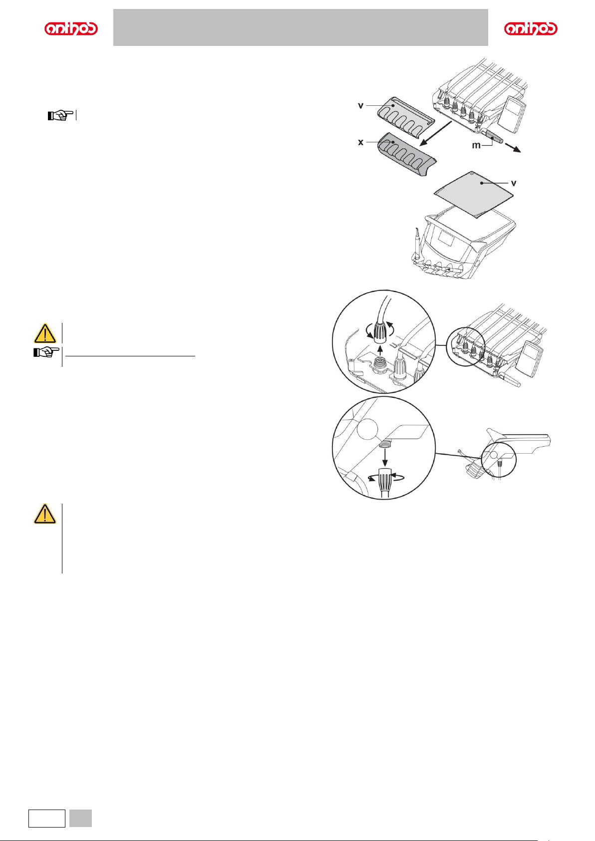
x Removable instrument holder; just slide it out of its seat to remove.
m Board handle that can be removed and sterilized in an autoclave at up to
121°C.
To remove the handle, first press the special locking buttons.
v Silicone protection that can be sterilized in an autoclave at up to 135°C.
Removable instrument hoses.
Clean and sanitise the external surface of the instrument hose using a
suitable product (see paragraph 1.4).
Instrument hoses are NOT designed for sterilization in
autoclave or by being cold soaked in solution.
Boards, version with Upper Recovery: to remove hoses, first remove
instrument holder (x).
• Before removing instrument hoses, turn dental unit off.
• After having turned dental unit off, drain syringe ducts by pressing the relevant air and water buttons directly on bowl until all spray
water has flowed out.
• TURBINE, MICROMOTOR and SCALER instrument hoses contain water; it is therefore recommended to remove the hose by keeping
the handpiece side end on the bowl.
• When refitting a hose, make sure that electric contacts are dry and that the plastic ring nut is well tightened.
• Each hose must be refitted only and exclusively inside the corresponding instrument holder.
Page 25
A5 - A6 PLUS - L6
EN
25
5.1. DENTIST’S CONTROL CONSOLE
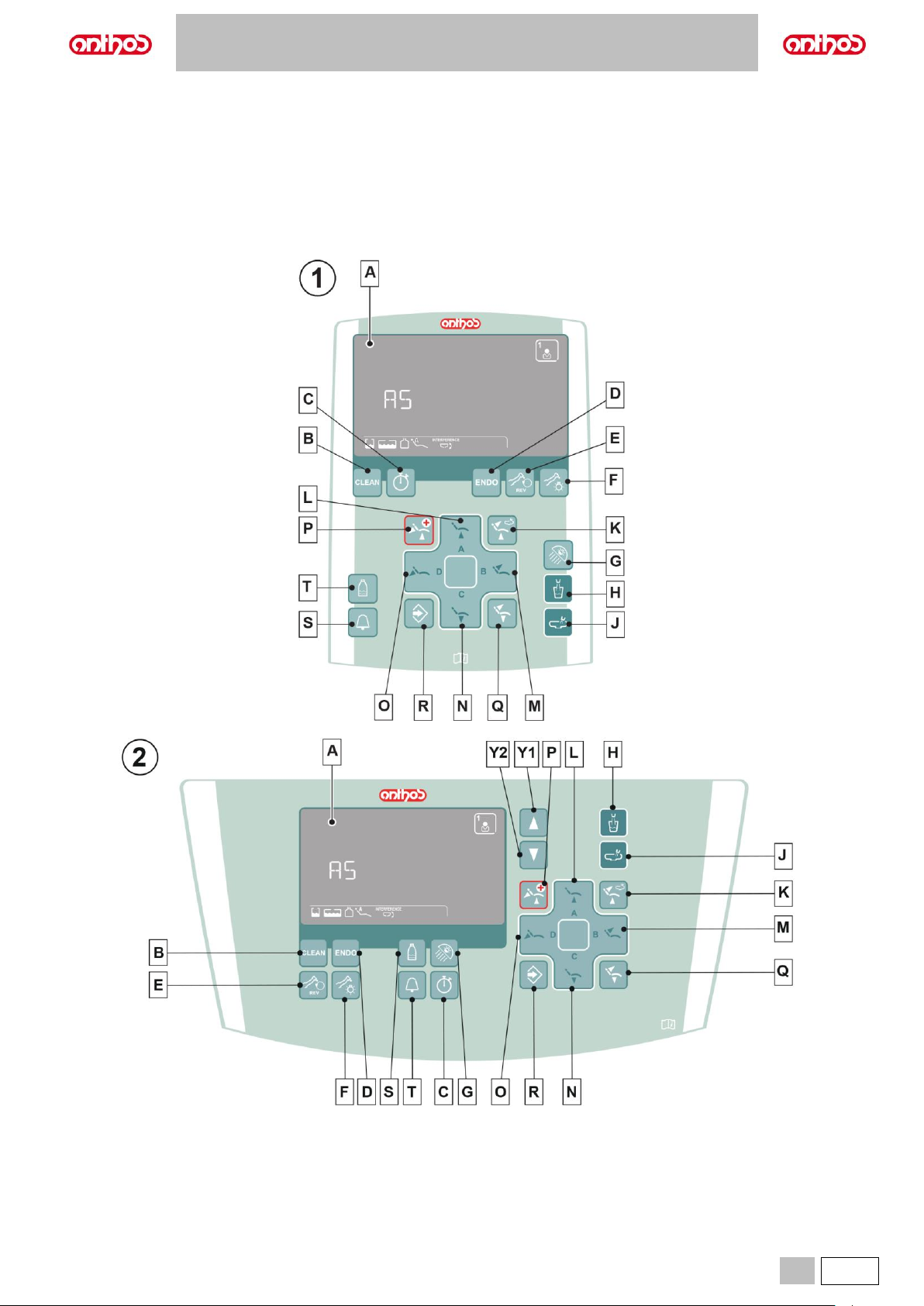
The console consists of a control panel and a DISPLAY of the LCD Touch type (A).
Upon turning on, the dental unit runs a short self-diagnosis cycle ending when the MAIN SCREEN appears on the DISPLAY showing the machine model,
the name of the last set operator and the active warning icons.
1 Console with LCD Touch DISPLAY (dental units in CONTINENTAL versions).
It allows viewing the machine’s operating steps and setting some parameters using touch keys.
2 Console with LCD Touch DISPLAY (dental units in INTERNATIONAL - CART SIDE DELIVERY versions).
It allows viewing the machine’s operating steps and setting some parameters using touch keys.
Page 26
A5 - A6 PLUS - L6
26
EN
Description of CONSOLE buttons:
B
Button lock
(pressed and held for at least 5 sec. for
Clean function).
L
Button pressed shortly: recall stored
position “A”.
Button pressed and held: seat up.
U
Decreases settable values.
C
Stopwatch
(see paragraph 5.1.1.2.).
M
Button pressed shortly: recall stored
position “B”.
Button pressed and held: backrest up.
V
Increases settable values.
D
Operating mode selection.
(Micromotor and Scaler).
N
Short press: recall stored position “C”.
Long press: seat down.
W
Negatoscope light On/Off.
E
Reversing micromotor drill rotation
direction.
O
Button pressed shortly: Recall stored
position “D”.
Button pressed and held: backrest down.
X
Negatoscope.
F
Fiber optics on/off.
P
Emergency position recall.
Y1
Dentist's board up button
(SIDE DELIVERY models)
or board brake release
(INTERNATIONAL - CART models).
G
Operating light On/Off.
Q
Dental chair reset position (patient
entry/exit).
Y2
Dentist's board down button
(SIDE DELIVERY models)
or board brake release
(INTERNATIONAL - CART models).
H
Water-to-cup delivery.
R
Enabling dental chair position storage.
J
Water-to-bowl delivery.
S
Assistant's call.
K
Rinse position recall.
T
S.H.S. system enabling/disabling
(if system is installed).
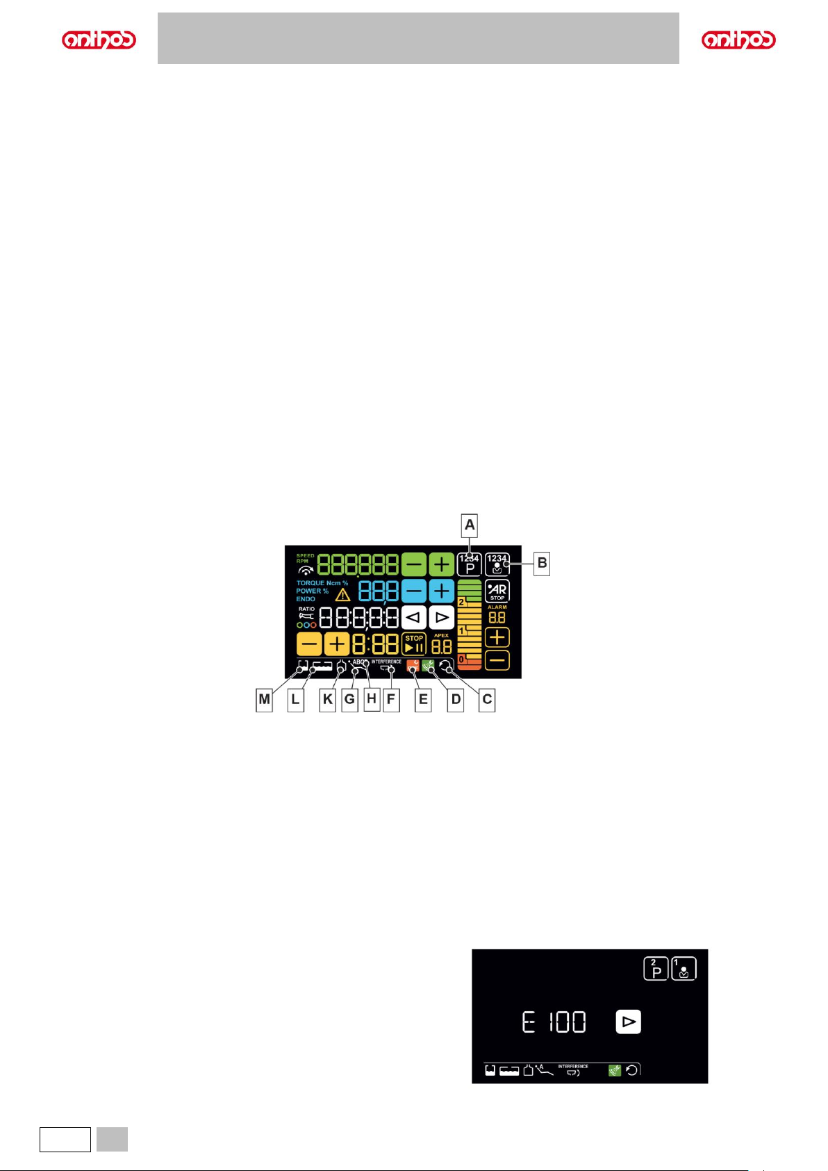
Warning icons.
The DISPLAY shows a series of icons giving information on the dental unit operation.
Description of the warning icons:
A
Active work programme.
G
Dental chair position set manually.
B
Active operator.
H
Dental chair stored position “A”, “B”, “C” or “D”.
C
Reverse micromotor rotation.
K
Independent water supply on.
D
Instrument spray active.
L
Independent water supply tank in reserve
E
Instrument spray NOT active.
M
Disinfectant fluid tank in reserve.
F
Bowl inside interference area.
Standby condition.
After about 10 minutes of inactivity, the dental unit goes into standby mode.
Standard operating conditions will be resumed as soon as any operation is carried out.
Error / warning messages.
During the different operating steps, the system could detect some
malfunctions/faults of the dental unit.
In this case, two types of notices can be displayed on the console DISPLAY:
warning messages (W xxx) and error messages (E xxx) (see paragraph 10).
If the malfunction/fault is not dangerous, the dental unit continues working.
The message can be turned off by pressing any button on the console.
Page 27
A5 - A6 PLUS - L6
EN
27
5.1.1. MAIN SETTINGS
5.1.1.1. HYGIENE CYCLE SETTING
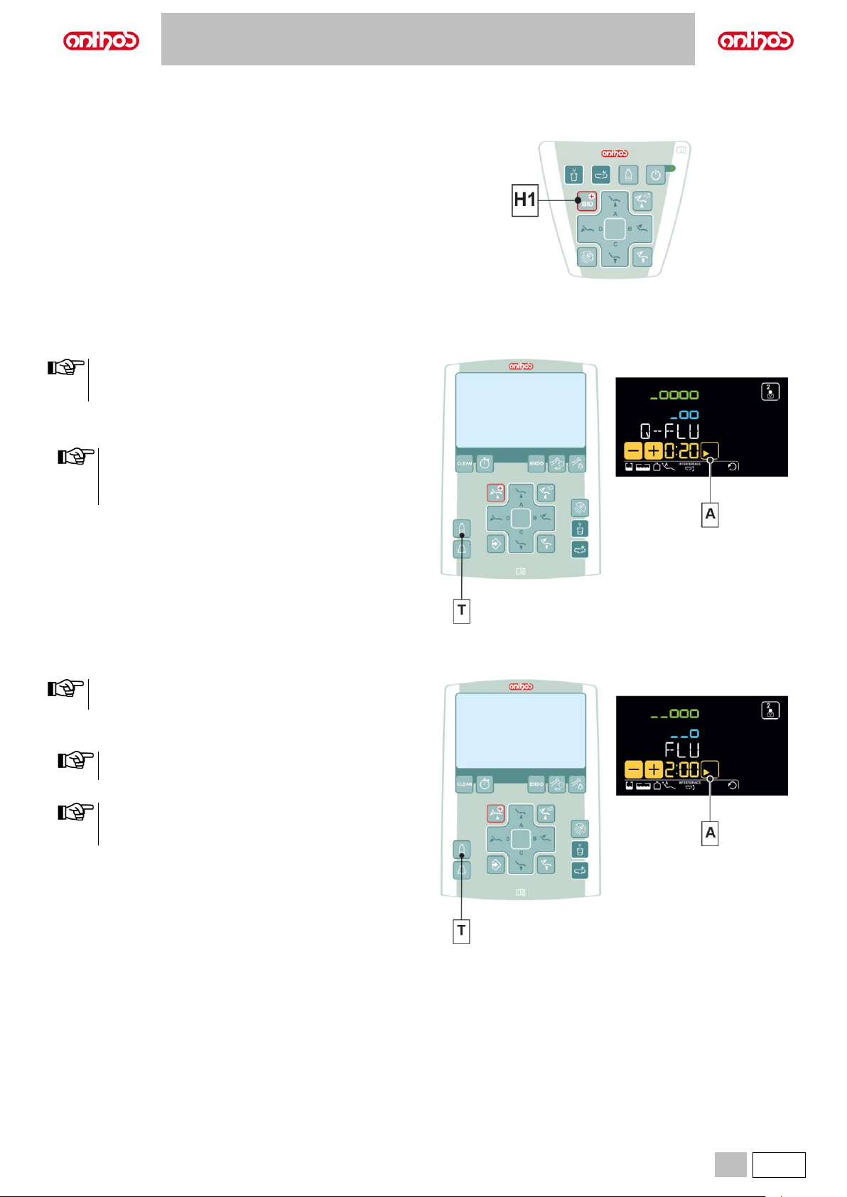
• Press button (H1) on the assistant's board to open the HYGIENE
CYCLE SETTING menu:
H1 Hygiene cycle setting menu.
Button pressed shortly: FLUSHING cycles.
Button pressed and held: BIOSTER S cycle.
5.1.1.1.1. QUICK FLUSHING CYCLE SETTING
• We recommend carrying out this operation after seeing each
patient.
• The cycle time is about 20 seconds
Performing the cycle.
• Press the “-” touch button to select the QUICK FLUSHING cycle.
• When independent water supply is used for flushing,
submenu will NOT be available if level is in reserve. (see
paragraph 7.2).
• The cycle time is about 20 seconds.
• Extract the instruments to be treated (the selected instruments will be
highlighted on the LCD Touch DISPLAY).
• Press the button (T) to activate/deactivate independent water supply
(with S.H.S. system, only).
• Press the touch button (A) to start the QUICK FLUSHING cycle (see
paragraph 7.6.).
5.1.1.1.2. LONG FLUSHING CYCLE SETTING
We recommend performing this operation at the beginning of
each working day.
Performing the cycle.
• Press the “+” touch button to select the LONG FLUSHING cycle.
When independent water supply is used for flushing, submenu
will NOT be available if level is in reserve. (see paragraph 7.2).
• Set cycle time by using buttons “+” or “-“.
Time setting ranges from a min. of 2 minute to a max. of 10
minutes. When using the distilled water tank, do not set a time
higher than 2 minutes.
• Extract the instruments to be treated (the selected instruments will be
highlighted on the LCD Touch DISPLAY).
• Press the button (T) to activate/deactivate independent water supply
(with S.H.S. system, only).
• Press the touch button (A) to start the LONG FLUSHING cycle (see
paragraph 7.5.).
Page 28
A5 - A6 PLUS - L6
28
EN
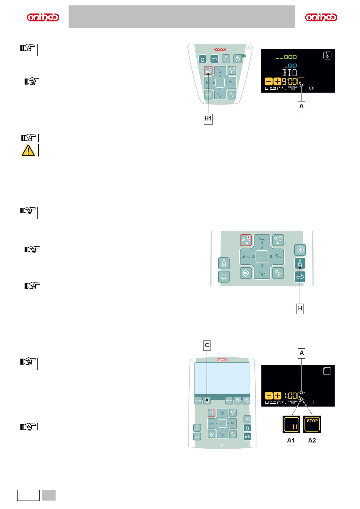
5.1.1.1.3. BIOSTER DISINFECTION CYCLE SETTING
We recommend carrying out this operation at the end of each
working day.
Performing the cycle.
• Press and hold the button (H1) on the assistant's board to select the
BIOSTER S cycle.
Cycle will not start if:
- disinfectant tank is in reserve (see paragraph 7.4.);
- an instrument is extracted;
- there is an error in the W.H.E. system
• Set cycle time by using buttons “+” or “-“.
Time setting ranges from a min. of 5 minutes to a max. of 10 minutes.
Disinfection according to the manufacturer's specifications is guaranteed by the 10-minute cycle, a shorter time may not guarantee
the same levels of disinfection.
• Extract the hoses to be treated (the selected hoses will be highlighted on the DISPLAY).
• Press the “PLAY” touch button (A) to start the BIOSTER S cycle (see paragraph 7.4.).
5.1.1.1.4. W.H.E. SYSTEM TANK EMPTYING
This function allows emptying the W.H.E. system water circuit (see
paragraph 7.3.).
This operation is recommended if the dental unit has been
switched off for more than 7 days.
Performing the emptying.
• Insert the special supplied cup under the spout.
• Press and hold button (H) for at least 5 seconds to start the emptying
cycle, the DISPLAY will show the system’s code illuminated.
Cycle will not start if:
- S.H.S. system is active;
- there is an error in the W.H.E. system.
The cycle end is signalled by a sound (3 BEEPS).
Now the dental unit is in lockout mode and it can be turned off.
At restart, the W.H.E. system will be automatically restored.
5.1.1.2. STOPWATCH
• Press button (C) to access the STOPWATCH function:
Stopwatch setting
The countdown can be set from a minimum of 10 seconds to a
maximum of 9 minutes and 59 seconds.
• Set the time using the touch buttons "+" and "-".
• Press the "PLAY" button (A) to start the countdown.
• Press the "PAUSE" button (A1) to stop the countdown.
Once the set time has elapsed, the dental unit emits an intermittent sound.
• Press the "STOP" button (A2) to stop the sound and select the last time
value set in the timer.
• Press and hold the "PAUSE" touch button (A1) to stop the countdown
and go back to the time setting step.
The last set time is stored.
Page 29
A5 - A6 PLUS - L6
EN
29
5.1.2. OPERATOR SELECTION
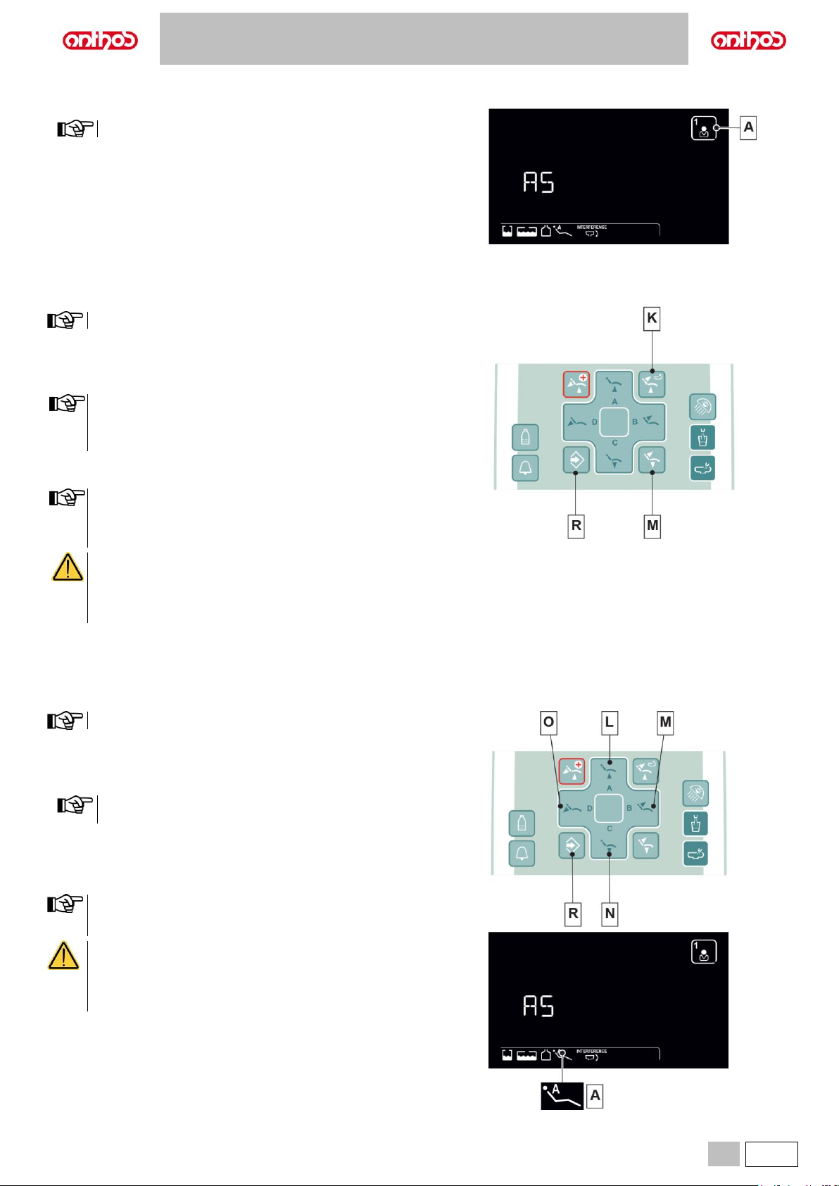
• Press button (A) repeatedly to set the desired operator.
There are 4 selectable operators.
5.1.3. DENTAL CHAIR "RINSING POSITION" AND "RESET POSITION" PROGRAMMING
This setting is specific for each single operator.
Proceed as follows:
• Adjust the dental chair into the desired position with the manual
movement buttons.
• Hold button (R) for at least 2 seconds to activate save mode.
for L6 series:
In the Rinse Position, the maximum seat height that can be saved
is the safety height (no interference between the seat and the
bowl).
• Press the buttons "Reset Position" (patient entry/exit) (M) or "Rinse
Position" (K) briefly to assign the position to the button.
The "Rinse Position" button (K) moves backrest and seat to rinse
position.
When button (K) is pressed again, backrest and seat will go back
to the previous position.
CRUSHING HAZARD
The positions already stored ensure a safety distance
between dental chair and floor. Do not store lower dental
chair positions, and in any case pay attention to the risk of
crushing.
5.1.4. PROGRAMMING THE DENTAL CHAIR POSITIONS A, B, C and D
This setting is specific for each single operator.
Proceed as follows:
• Adjust the dental chair into the desired position with the manual
movement buttons.
• Hold button (R) for at least 2 seconds to activate save mode.
The position of the dentist’s board is not stored in dental chair
programmes.
• Press the button (L), (M), (N) or (O) briefly to assign the position to the
button.
The appearance of icon (A) relating to the selected programme on the
LCD Touch DISPLAY will confirm that it has been saved.
To recall a programmed position, shortly press the button of the
selected programme.
CRUSHING HAZARD
The positions already stored ensure a safety distance
between dental chair and floor. Do not store lower dental
chair positions, and in any case pay attention to the risk of
crushing.
Page 30
A5 - A6 PLUS - L6
30
EN
5.1.5. EMERGENCY BUTTON
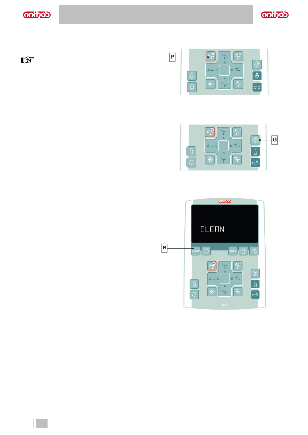
The button (P) can be used in the event of an emergency to move the
patient into the Trendelenburg position.
• The Trendelenburg position is already set and cannot be
changed
• For L6 series:
the emergency position is not activated if the bowl is in the
interference area (see paragraph 4.1).
5.1.6. TURNING ON THE OPERATING LIGHT
Press the button (G) to turn on/off the operating light.
5.1.7. CONSOLE CONTROL PANEL LOCKING BUTTON
Press this button to enable/disable the control panel and the LCD Touch
DISPLAY (if any) in order to easily carry out console cleaning operations.
• Press button (B) for at least 5 seconds to disable the control panel and
the LCD Touch DISPLAY (if any).
• Press again button (B) for at least 5 seconds to re-enable the control
panel and the LCD Touch DISPLAY (if any).
Page 31
A5 - A6 PLUS - L6
EN
31
5.2. FOOT CONTROL
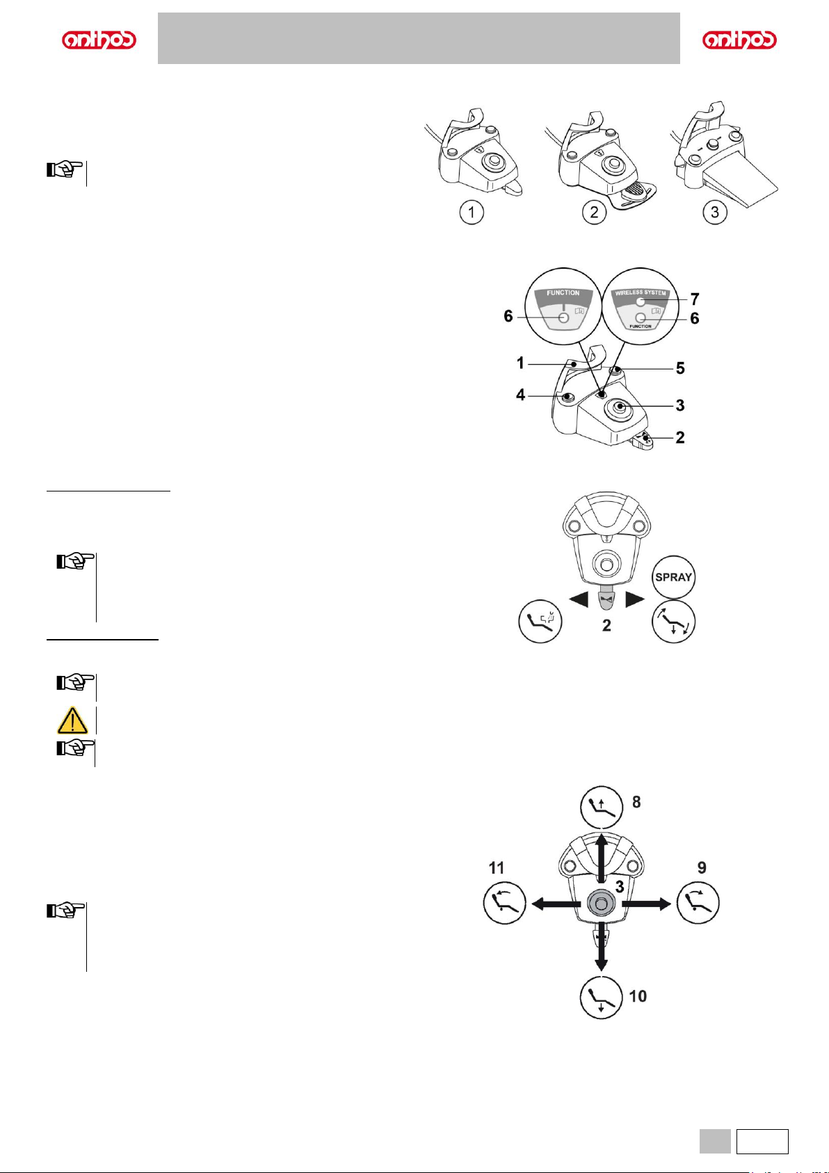
Three types of foot controls are available:
1 Multifunction (see paragraph 5.2.1.).
2 Pressure operated (see paragraph 5.2.2).
3 Power pedal (see paragraph 5.2.3).
The "Multifunction" and "Pressure-operated" foot controls can
also be supplied in WIRELESS version (see paragraph 5.2.5).
5.2.1. "MULTIFUNCTION” FOOT CONTROL
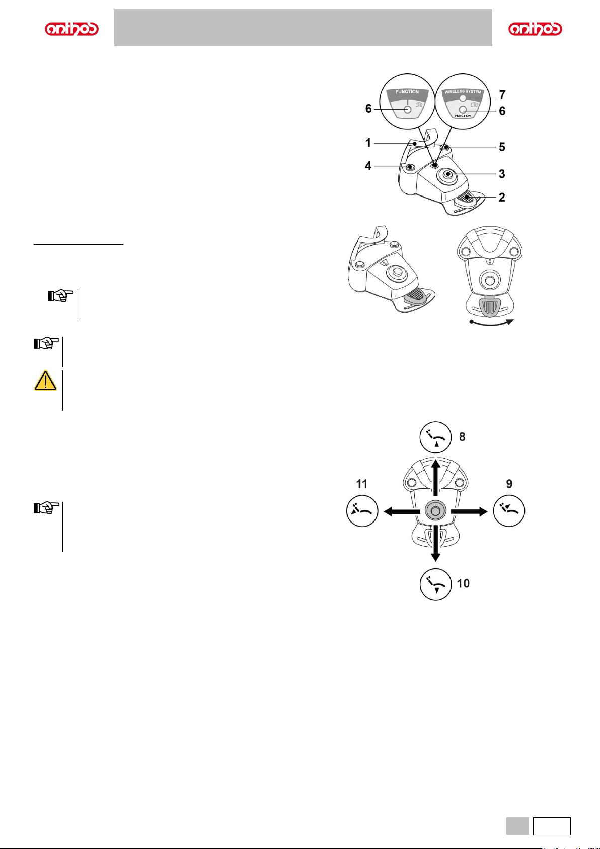
Description of the parts.
1 Handle.
2 Control lever.
3 Dental chair movements.
4 Chip-air/Patient rinse position recall control.
5 Water Clean System/Automatic dental chair return control.
6 LED (not active).
7 Battery charge LED (wireless version only).
Control lever (2).
With instrument removed
• Pushing the pedal (2) starts the instrument.
• Shifting the pedal (2) adjusts speed/power of the instrument:
- rightward: activation with spray.
- leftward: activation with no spray.
• The control lever adjusts the speed/power of the instrument
from the minimum to the maximum value set from the
dentist's board.
• At the end of work, air is automatically blown to eliminate any
drops of liquid remaining in the spray ducts.
With instrument at rest
• End-of-travel to the right: dental chair reset position recall.
• End-of-travel to the left: rinse position recall.
If the lever is pushed again all the way to the left, the dental
chair goes back to the work position.
These dental chair functions are activated by keeping the
pedal at the end of the travel for at least 2 seconds.
When the foot control is pressed, all automatic dental chair
movements are automatically blocked.
Joystick for dental chair movements (3).
It controls the following movements:
8 Dental chair seat up.
9 Dental chair backrest up.
10 Dental chair seat down.
11 Dental chair backrest down.
To stop movement, release the control joystick.
• All the buttons used to move the dental chair are inoperative
when an instrument is removed and the foot control lever is
actuated.
• It is possible to edit the joystick operation once the instrument
is extracted (see paragraph 5.1.1.7.).
Page 32
A5 - A6 PLUS - L6
32
EN
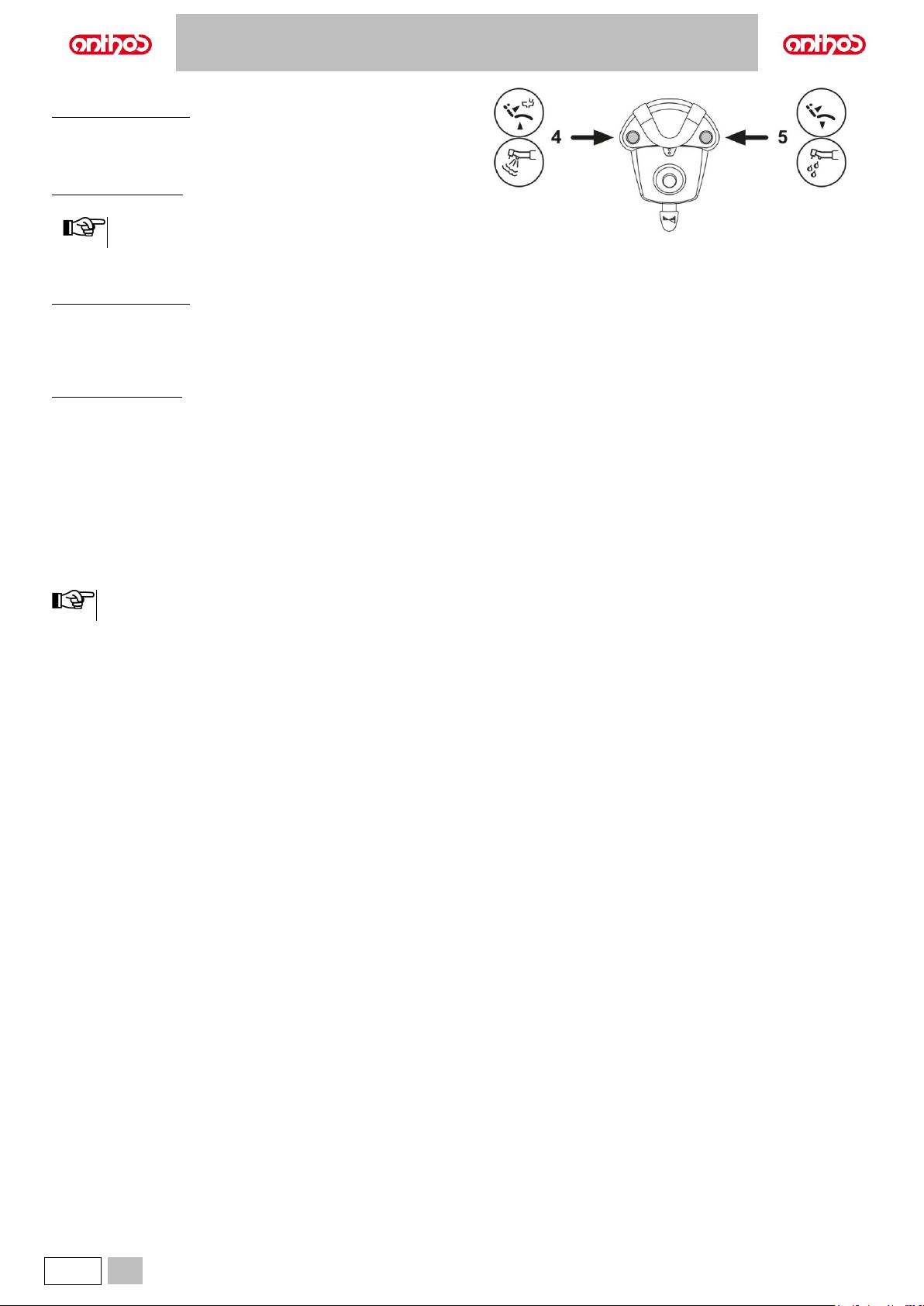
Left-hand button operation (4).
With instrument removed
• Short press: enables/disables the spray function.
• Long press (at least 2 seconds): sends a jet of air to the instruments
(Chip air); the jet stops when the button is released.
With instruments at rest
• Long press: calls up the patient rinse position.
Pressing the button a second time returns dental chair back
into working position.
Right-hand button operation (5).
With instrument removed
• Long press (at least 2 seconds): sends a jet of water to the instruments
(Turbine, Micromotor and Scaler) (Water Clean System function); the jet
stops when the button is released.
• Short press: enables/disables the spray function.
With instruments at rest
• Long press (at least 2 seconds): calls up the dental chair reset position.
WIRELESS version.
This foot control can also be supplied in wireless version (see Paragraph
5.2.4).
Protection against liquid penetration.
The foot control is protected against liquid penetration. Degree of
protection: IPX1.
Cleaning.
Clean the foot control using a suitable product (see Paragraph 1.5).
If the foot control slips on the floor, remove any dust from the slipproof rubber found under the base with a dry cloth.
Page 33
A5 - A6 PLUS - L6
EN
33
5.2.2. "PUSH-PEDAL” FOOT CONTROL
Description of the parts.
1 Handle.
2 Control lever.
3 Dental chair movements.
4 Chip-air/Patient rinse position recall control.
5 Water Clean System/Automatic dental chair return control.
6 Spray operation LED.
7 Battery charge LED (wireless version only).
Control lever (2).
With instrument removed
• Pushing the pedal (2) for a long time starts the instrument.
• Shifting the pedal (2) adjusts speed/power of the instrument:
- to the right: increase;
- to the left: decrease.
The control lever adjusts the speed/power of the instrument
from the minimum to the maximum value set from the
dentist's board.
Release the pedal (2) to stop instrument operation.
With the spray active, at the end of the operation a blast of air is
automatically activated to remove any residual drops of liquid in
the spray ducts.
• A short sound warns of the switching.
When the LED (6) is on, it indicates operation WITH spray.
• When the pedal (2) is pressed, all automatic dental chair
movements are automatically blocked.
Joystick for dental chair movements (3).
It controls the following movements:
8 Dental chair seat up.
9 Dental chair backrest up.
10 Dental chair seat down.
11 Dental chair backrest down.
To stop movement, release the control.
• All the buttons used to move the dental chair are inoperative
when an instrument is removed and the foot control lever is
actuated.
• It is possible to edit the joystick operation once the instrument
is extracted (see paragraph 5.1.1.7.).
Page 34
A5 - A6 PLUS - L6
34
EN
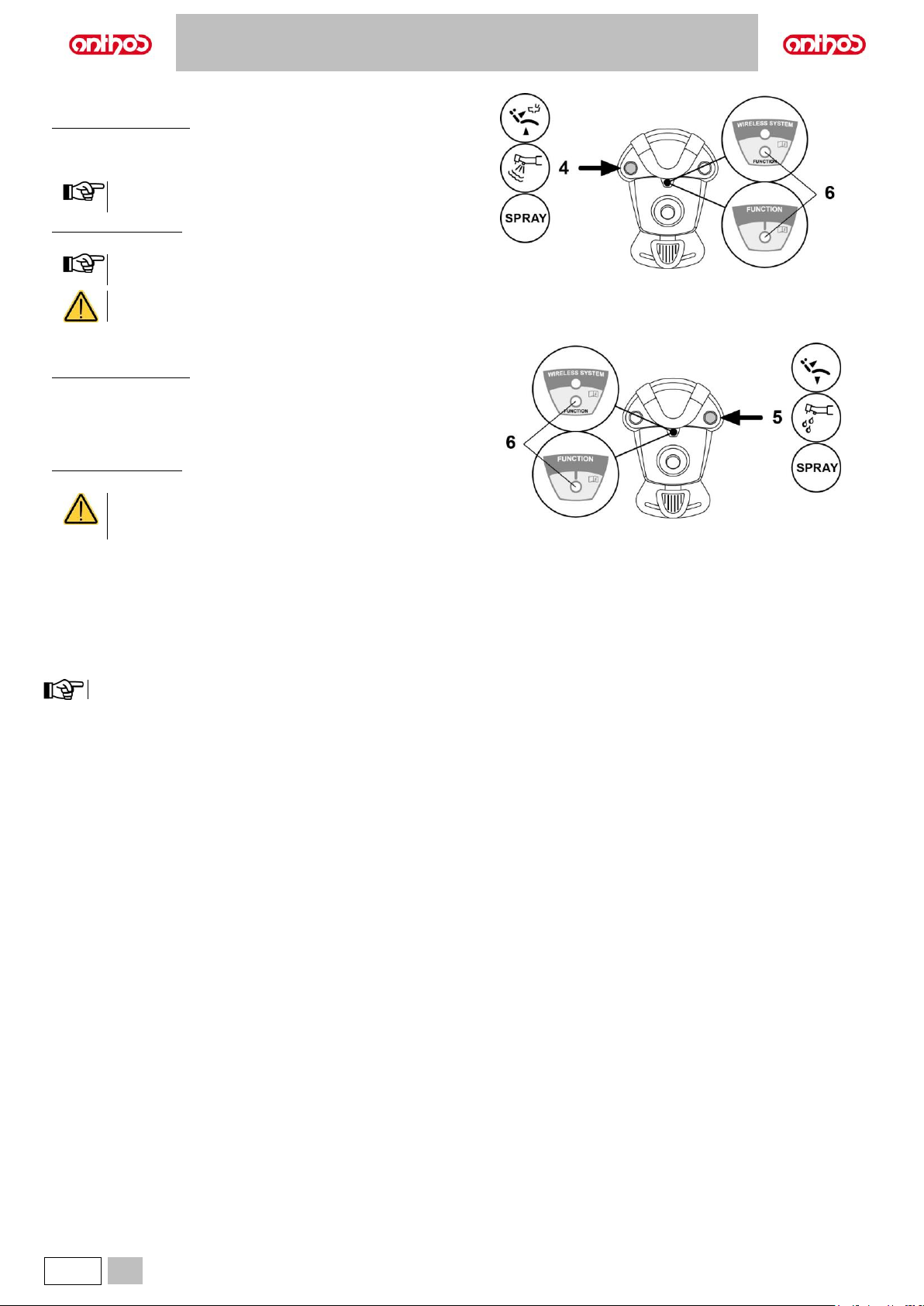
Left-hand button (4).
With instrument removed
• Short press: enables/disables the spray function.
• Long press (at least 2 seconds): sends a jet of air to the instruments
(chip air); the jet stops when the button is released.
The control works only when the Turbine and Micromotor are
in working position.
”
With instruments at rest
• Long press (at least 2 seconds): calls up the patient rinse position.
Pressing the button a second time returns dental chair back
into working position.
• A short sound warns of the switching.
When the LED (6) is on, it indicates operation WITH spray.
Right-hand button (5).
With instrument removed
• Long press (at least 2 seconds): sends a jet of water to the instruments
(Turbine, Micromotor and Scaler) (Water Clean System function); the jet
stops when the button is released.
• Short press: enables/disables the spray function.
With instruments at rest
• Long press (at least 2 seconds): calls up the reset position.
• A short sound warns of the switching.
When the LED (6) is on, it indicates operation WITH
spray.
WIRELESS version.
This foot control can also be supplied in WIRELESS version (see "WIRELESS foot control" paragraph).
Protection against liquid penetration.
The foot control is protected against liquid penetration. Degree of protection: IPX1.
Cleaning.
Clean the foot control using a suitable product (see Paragraph 1.5).
If the foot control slips on the floor, remove any dust from the slip-proof rubber found under the base with a moist cloth.
Page 35
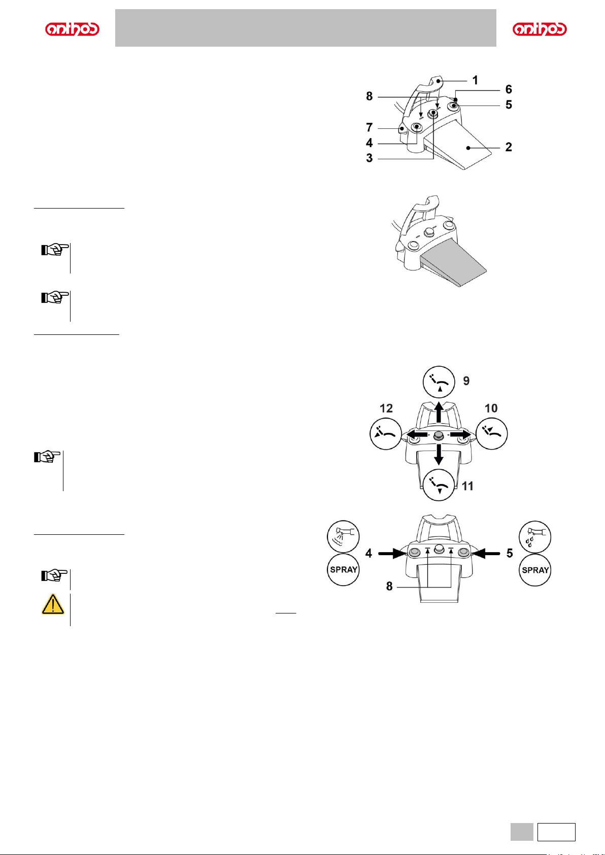
A5 - A6 PLUS - L6
EN
35
5.2.3. "POWER PEDAL" FOOT CONTROL
Description of the parts.
1 Handle.
2 Foot control.
3 Dental chair movement control.
4 Chip-air control or activation/deactivation of instrument spray function.
5 Water Clean System control or activation/deactivation of instrument
spray function.
6 Automatic dental chair return or programme "B” recall activation.
7 Patient rinse position or programme "A" recall activation.
8 Spray operation LED.
Foot control (2).
With instrument removed
• Pushing the pedal (2) for a long time starts the instrument.
You can adjust the speed/power by modulating the pressure on the
pedal.
The foot control adjusts the speed/power of the instrument
from the minimum to maximum value set from the dentist's
board.
• Release the pedal (2) to stop instrument operation.
With the spray active, at the end of the operation a blast of air
is automatically activated to remove any residual drops of
liquid in the spray ducts.
With instruments at rest
• When the foot control (2) is pressed, all automatic dental chair
movements are automatically blocked.
Joystick for dental chair movements (3).
It controls the following movements:
9 Dental chair seat up.
10 Dental chair backrest up.
11 Dental chair seat down.
12 Dental chair backrest down.
To stop movement, release the control.
• All dental chair movements are blocked when an instrument is
being used or the BIOSTER S system is running.
• It is possible to edit the joystick operation once the instrument
is extracted (see paragraph 5.1.1.7.).
Left-hand button (4).
With instrument removed
• Short press: enables/disables the spray function.
• Long press (at least 2 seconds): sends a jet of air to the instruments
(Chip air); the jet stops when the button is released.
The control works only when the Turbine and Micromotor are
in working position.
• A short sound warns of the switching.
When the LEDs (8) are on, they indicate operation WITH
spray.
Page 36
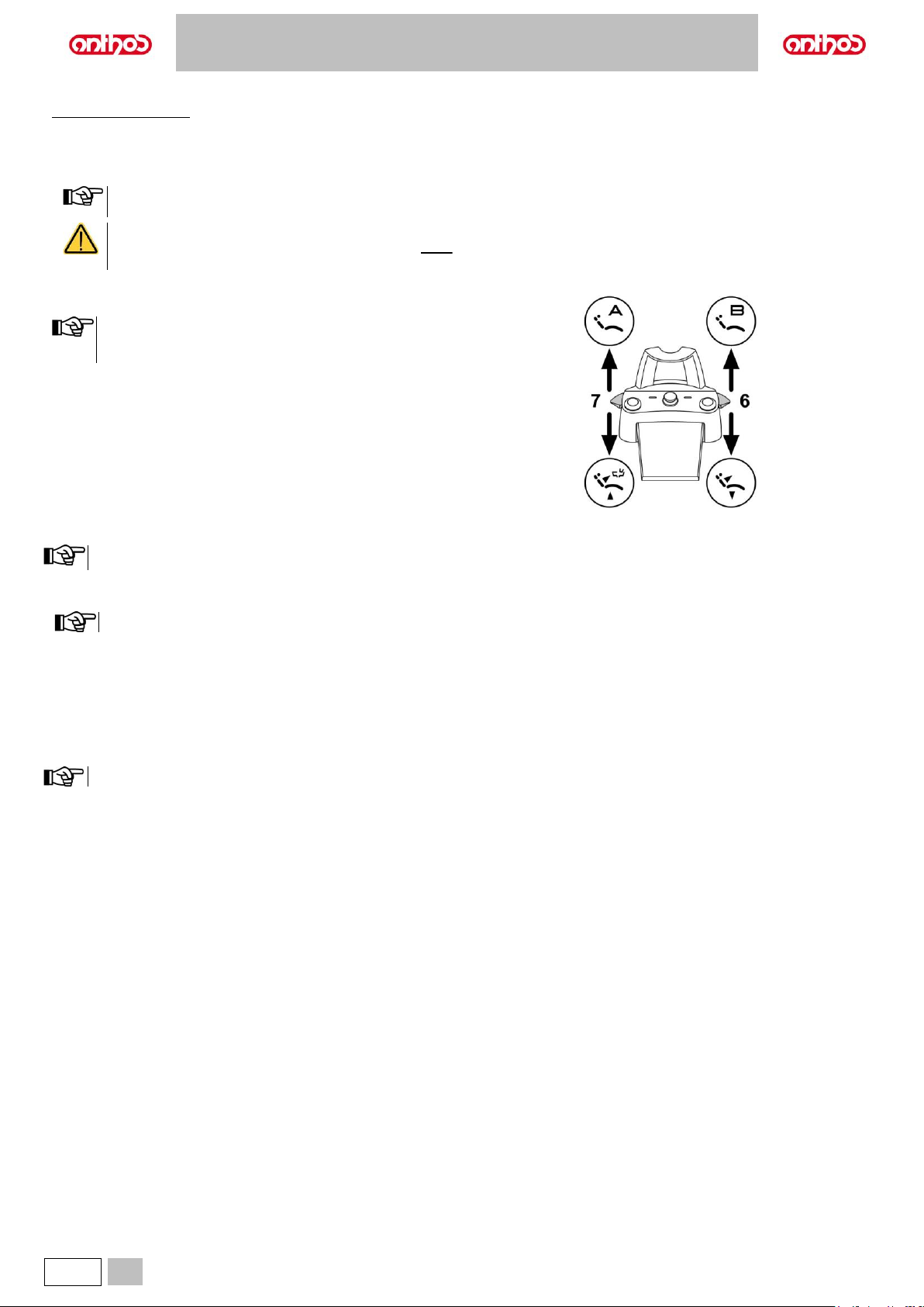
A5 - A6 PLUS - L6
36
EN
Right-hand button (5).
With instrument removed
• Long press (at least 2 seconds): sends a jet of water to the instruments
(Turbine, Micromotor and Scaler) (Water Clean System function); the jet
stops when the button is released.
• Short press: enables/disables the spray function.
The control works only when the Turbine and Micromotor are
in working position.
• A short sound warns of the switching.
When the LEDs (8) are on, they indicate operation WITH
spray.
Right-hand lever (6).
With instruments at rest, the lever can control all dental chair
movements; with instruments removed, only down controls are
active.
Pressure:
• recalls dental chair reset position (patient entry/exit).
Lifted:
• recalls the stored dental chair position "B".
Left-hand lever (7).
With instruments at rest, the lever can control all dental chair movements; with instruments removed, only down controls are active.
Pressure:
• recalls patient rinse position.
When the lever is actuated the second time, the dental chair reaches its work position.
Lifted:
• recalls the stored dental chair position "A".
Protection against liquid penetration.
The foot control is protected against liquid penetration. Degree of protection: IPX1.
Cleaning.
Clean the foot control using a suitable product (see Paragraph 1.5).
If the foot control slips on the floor, remove any dust from the slip-proof rubber found under the base with a moist cloth.
Page 37
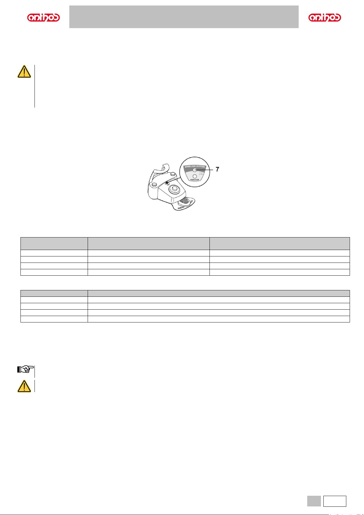
A5 - A6 PLUS - L6
EN
37
5.2.4. WIRELESS FOOT CONTROL
The "Multifunction" and "Push-pedal" foot controls can also be supplied in WIRELESS version.
Warnings for use.
• Avoid keeping the WIRELESS foot control in proximity of other RF sources, such as wireless LAN cards, other radio devices, home
RF devices, microwave ovens. The recommended distance is at least 2 metres in the case of microwave ovens and 1 metre in all
other cases.
• It is recommended NOT to use it in proximity of life support equipment (e.g. pacemakers or heart stimulators) and hearing aids.
Before using any electronic device in health facilities, always check that it is compatible with the other equipment present.
• Exclusively use the dental unit to charge the battery of the WIRELESS foot control.
• The internal battery may only be replaced by a qualified technician.
Warnings for first use.
It is advisable to fully charge the foot control battery before using it for the first time.
WIRELESS foot control operation.
The WIRELESS foot control operates exactly in the same way as the wired version, therefore refer to the paragraphs above paying WARNING to the
specific model used.
In addition, the WIRELESS foot control has a specific LED (7) that indicates the battery charge and the communication status with the dental unit.
LED indications (7).
The colour of the LED indicates the battery charge, while the type of flashing indicates the communication status with the dental unit.
Battery charge:
COLOUR
DESCRIPTION
( CABLE DISCONNECTED )
DESCRIPTION
( CABLE CONNECTED )
GREEN
Battery charge (>75%)
Battery charged
ORANGE
Battery charge (<50%)
Battery charging
RED
Battery needs charging (<25%)
Battery charge error
Off
Battery flat
Dental unit off or foot control fault
Communication status:
BLINKING
DESCRIPTION
Slow
Connection active in wireless mode
Fast
Connection active with charging cable inserted
Double
Connection search
Off
Communication error
Battery characteristics.
The WIRELESS foot control is equipped with a rechargeable battery.
The battery life is approximately 2 months (estimating 8 hours of consecutive daily operation) with the battery fully charged and fully efficient. The battery
efficiency reduces over time. It is estimated that the efficiency is reduced to 60% after 500 complete recharging cycles. Also in this condition, the battery
should last about 1 month.
When the battery efficiency is so reduced as to be deemed unsatisfactory to support the daily usage requirements, have it replaced by a
qualified technician.
Do not attempt to replace the battery yourself.
Page 38
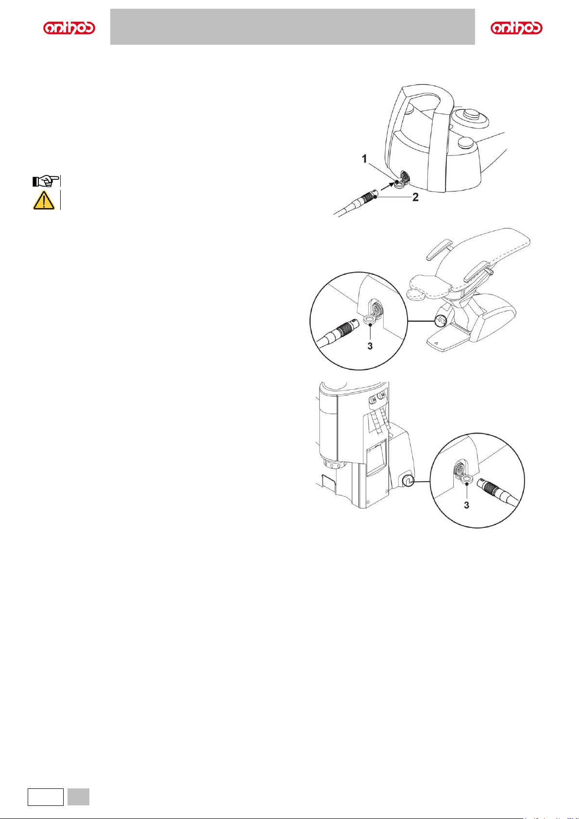
A5 - A6 PLUS - L6
38
EN
Limited battery warranty.
The battery in the foot control is covered by a 6-month warranty from the date of installation.
Recharging the battery.
When the batteries in the WIRELESS foot control need to be recharged.
Proceed as follows:
• Open the door (1) on the back of the pedal and connect the charging
cable (2).
• Open the door (3) at the base of the dental chair and connect the other
end of the charging cable (2).
At this point, the foot control is in the battery charging phase (battery
charging warning LED on) even though remaining fully functional.
The battery is fully recharged in about 6 hours.
Exclusively use the dental unit to charge the battery of the
WIRELESS foot control.
Natural battery discharge.
Should the battery not be used for long periods of time, it may slowly
discharge all the same.
If unused for long periods of time, it is advisable to always fully charge the
battery before use.
Maintenance and disposal
The wireless foot control does not contain parts that can be repaired
directly by the user.
In the event of a malfunction, do not attempt to carry out maintenance
operations, but directly contact the manufacturer or its local distributor at
the numbers indicated in the warranty certificate.
At the end of its lifetime, the battery must be replaced by a specialised
technician at a Service centre.
Page 39
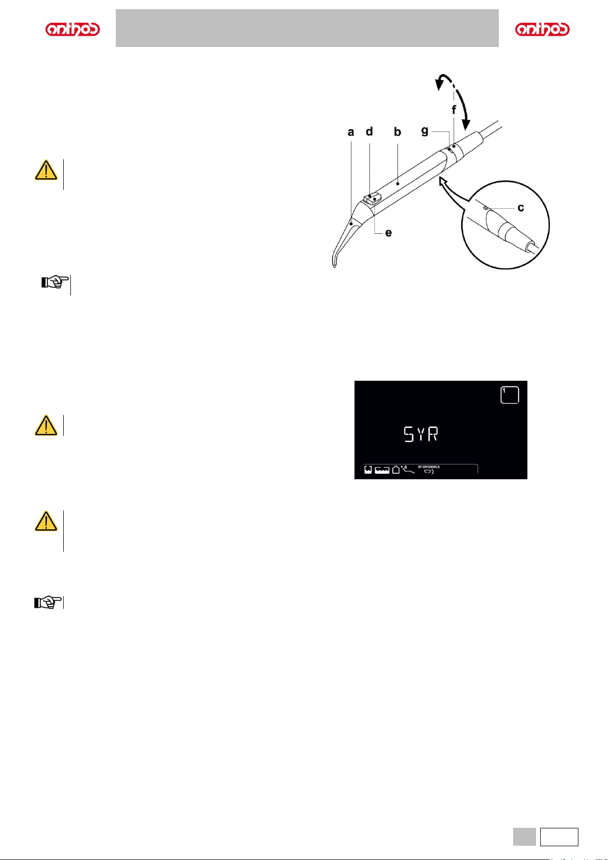
A5 - A6 PLUS - L6
EN
39
5.3. SYRINGE
Description of the instrument.
a Spout.
b Handle.
c Syringe release button.
d Air button.
e Water button.
f Hot/cold selector (only for 6-function syringes).
g Hot/cold indicator LED (only for 6-function syringes).
The instrument is supplied non-sterile.
It is recommended to use disposable infection control
sheaths and spouts.
Syringe models and operating times:
- syringe 3F: continuous operation,
- syringe 6F: 5 sec. operation, 10 sec. rest,
- syringe 6F (with fiber optics): 5 sec. operation, 10 sec. rest.
Use.
• Place the instrument in its work position.
Instrument activation is highlighted by the relevant managing
screen appearing on the DISPLAY.
Button (e) = water;
Button (d) = air;
Button (e + d) = spray.
6F syringe, operation with hot water, air and spray: turn the selector switch
(f) clockwise (LED g on).
6F syringe, operation with cold water, air and spray: turn the selector
switch (f) counter-clockwise (LED g off).
Removing the handle.
The spout (a) is screwed onto the handle (b).
Press the locking button (c) to take the handle off the syringe casing.
Carry out this operation with heater off.
Removable hose.
The instrument features a removable hose to make cleaning operations
easier (see paragraph 5.).
Cleaning.
Use soft disposable paper towel dampened with detergents/disinfectants.
• Do not soak the syringe in liquid disinfectants or
detergents.
• Inadvisable products: abrasive products and/or products
containing acetone, chlorine and sodium hypochlorite.
Sterilization.
Syringe handle and spout: steam autoclave at up to
135°C following the instructions for use of the device.
Bag before sterilizing.
Page 40
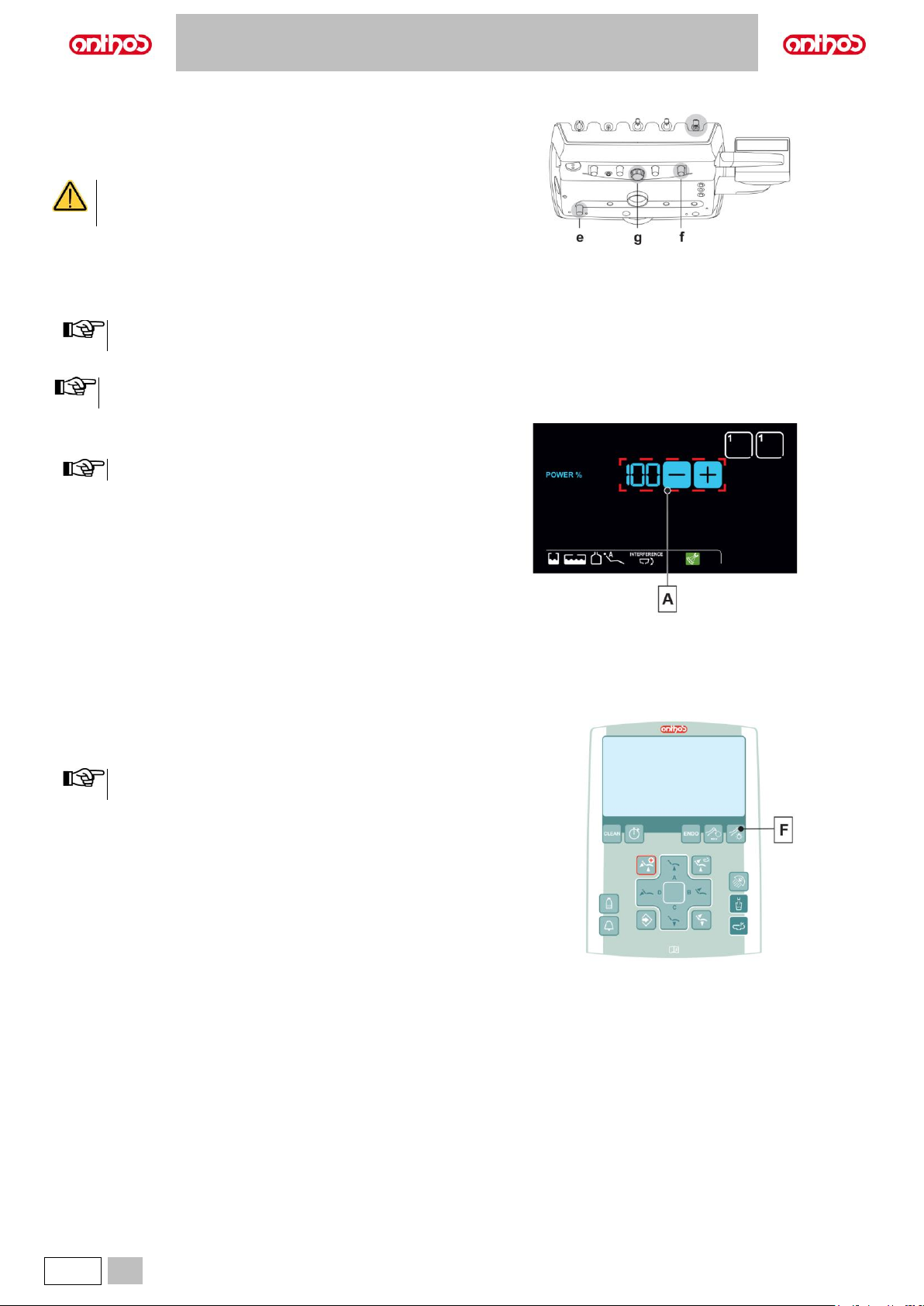
A5 - A6 PLUS - L6
40
EN
5.4. TURBINE
Connecting the handpiece and changing the drill.
Refer to the specific instructions provided with the handpiece.
Use.
The instrument is supplied NON-sterile.
Carefully read the operating instructions supplied with the
instrument before attempting to sterilize.
Operating times: work 5 min., rest 5 min.
f Cock that adjusts the amount of spray water
e Cock that adjusts the amount of air spray for all the instruments.
g Turbine return air filter.
• Place the instrument in its work position.
Instrument activation is highlighted by the relevant managing
screen appearing on the DISPLAY.
• Use the foot control lever to start the instrument (see paragraph 5.2.).
The turbine hose can also be used to connect the air micromotors equipped with 4-way connectors and conforming with standard ISO 13294
and/or other air-operated instruments with the same 4-way connector.
Adjusting the drill’s rotation speed:
• Set the percentage of drill’s maximum rotation speed using buttons (A)
The data set are automatically saved.
Turning on the fiber optics.
• Place the instrument in its work position.
• Press the button to turn Fiber Optics on/off (F).
The Fiber Optics switch off when the turbine is not used for 30
seconds (rheostat lever disabled).
Page 41
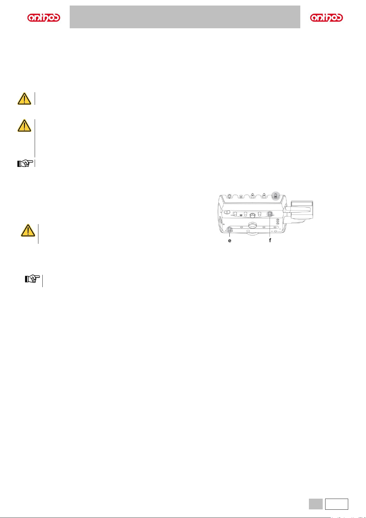
A5 - A6 PLUS - L6
EN
41
Removable hose.
The instrument features a removable hose to make cleaning operations easier (see paragraph 5.).
Cleaning and maintenance.
Refer to the specific instructions provided with the instrument.
It is recommended to use Daily Oil Plus (CEFLA s.c.) for lubrication.
Sterilization.
Steam autoclave up to 135°C following the instructions for the use of the device.
Carefully read the operating instructions supplied with the instrument before attempting to sterilize.
Safety standards.
• The turbine must never be started without attaching the drill or fake drill.
• The drill release button must not be pressed during operation!
Friction between the button and micromotor rotor overheats the head and may cause burns.
• The patient’s internal tissues (tongue, cheeks, lips, etc.) must be protected against contact with the button by using suitable
instruments (mirrors, etc.).
• The drills and various instruments attached to the handpieces must comply with Biocompatibility Standard ISO 10993.
When the peristaltic pump is enabled, the other sources of liquid supply are disabled
5.5. ELECTRIC MICROMOTOR
Coupling the handpieces and changing the drill.
Refer to the specific instructions provided with the micromotor and various
handpieces.
Use.
The instrument is supplied NON-sterile.
Carefully read the operating instructions supplied with the
instrument before attempting to sterilize.
Operating times: work 5 min., rest 5 min.
e Cock that adjusts the amount of air spray for all the instruments.
f Cock that adjusts the amount of spray water.
• Place the instrument in its work position.
Instrument activation is highlighted by the relevant managing
screen appearing on the DISPLAY.
• Use the foot control lever to start the instrument (see paragraph 5.2).
Page 42
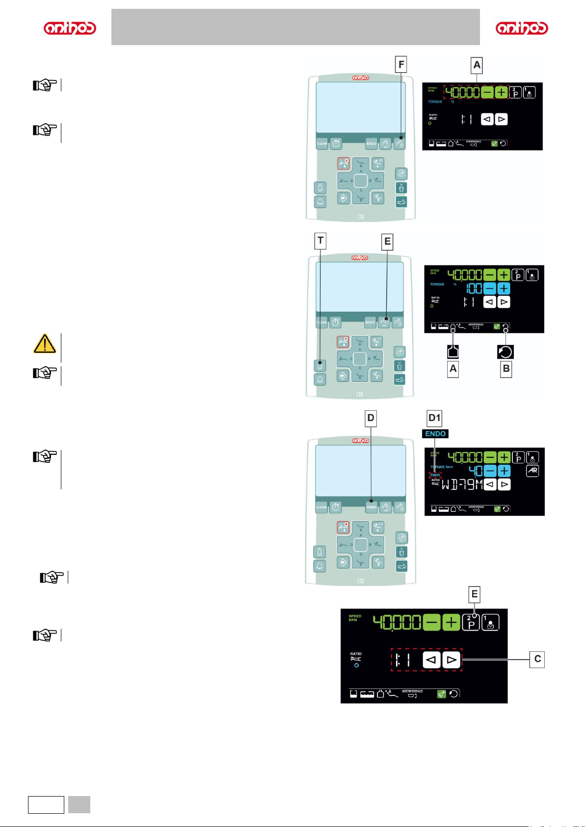
A5 - A6 PLUS - L6
42
EN
Adjusting the drill’s rotation speed.
Set the percentage of drill’s maximum rotation speed using buttons (A).
The data set are automatically saved.
Turning on the fiber optics.
Press the button to turn Fiber Optics on/off (F).
The Fiber Optics switch off when the turbine is not used for 30
seconds (rheostat lever disabled).
Activation/deactivation of independent water supply
(only with S.H.S. system).
• Press button (T) to activate/deactivate the independent water supply:
The icon (A) appearing on the DISPLAY indicates that the independent
water supply is active.
Reversing micromotor drill rotation direction.
• Select micromotor drill rotation direction by pressing button (E):
The reversed rotation direction is signalled by a sound (3 BEEPS) and by
icon (B) appearance on the DISPLAY.
As soon as the micromotor is extracted, in addition to the
icon (B), a sound (3 BEEPS) warns the operator if the
direction of rotation is reversed.
When the rheostat lever is on, the micromotor drill cannot reverse
its direction of rotation.
Selecting the operating modes (LCD Touch DISPLAY only).
If supported by the micromotor, select RESTORATIVE (see paragraph
5.5.1.) or ENDODONTIC (see paragraph 5.5.2.) operating modes using
button (D).
• The activation of ENDODONTIC mode is signalled on the LCD
Touch DISPLAY through icon (D1).
• Machines equipped with a basic motor only provide the
RESTORATIVE operating mode.
Selecting the micromotor working programmes (LCD Touch
DISPLAY only).
It is possible to set 4 micromotor working programmes.
Each working programme saves the following data:
- Operating mode.
- Maximum rotation speed.
- Handpiece reduction ratio.
The data set are automatically saved.
• Press button (E) repeatedly to set the desired working programme.
Selecting the reduction ratio (LCD Touch DISPLAY only).
Select the desired reduction ratio using buttons (C).
The data set are automatically saved.
Page 43
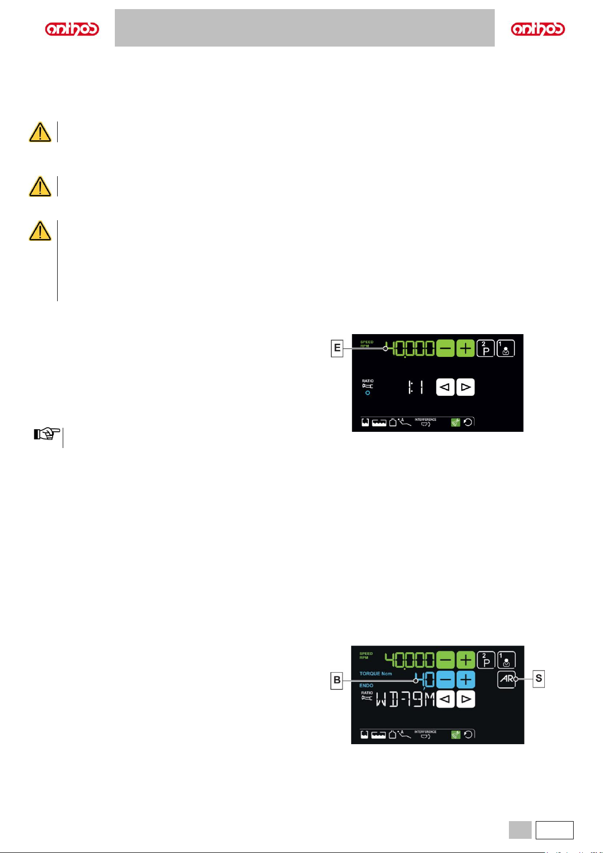
A5 - A6 PLUS - L6
EN
43
Removable hose.
The micromotor features a removable hose to make cleaning operations easier (see paragraph 5.).
Cleaning and maintenance.
Refer to the specific instructions provided with the instrument.
It is recommended to use Daily Oil Plus (CEFLA s.c.) for lubrication.
• Do not soak the instrument in disinfectant fluids or detergents.
• Inadvisable products: abrasive products and/or products containing acetone, chlorine and sodium hypochlorite.
Sterilization.
Instrument handpiece only: see paragraph 1.6.
Carefully read the operating instructions supplied with the instrument before attempting to sterilize.
Safety standards
• The instrument is supplied NOT sterile and must be sterilized before use.
Carefully read the operating instructions supplied with the instrument before attempting to sterilize.
• Never put the contra angle on the micromotor while it is running.
• The drill release button must not be pressed during operation!
Friction between the button and micromotor rotor overheats the head and may cause burns.
• The patient’s internal tissues (tongue, cheeks, lips, etc.) must be protected against contact with the button by using suitable
instruments (mirrors, etc.).
• The drills and various instruments attached to the handpieces must comply with Biocompatibility Standard ISO 10993.
5.5.1. RESTORATIVE OPERATING MODE
Characteristics.
- Speed range: 100 to 40,000 Rpm (1:1 handpiece).
- Reduction ratio selection.
- Display of the instantaneous maximum speed.
- Direct selection of the set working programmes.
Menu with micromotor extracted but not active.
All icon buttons are active and all available functions can be edited (see
paragraph 5.5.).
Any edited setting or value will be automatically saved inside the
selected working programme (e.g. P1).
Menu with micromotor extracted and active.
The following functions can be changed:
• Adjust the maximum rotation speed of the drill (E) using the buttons “+”
or “-”“.
5.5.2. ENDODONTIC OPERATING MODE
Characteristics.
- Speed value adjustable from 100 to 1200 Rpm with value always
referring to the drill, based on the set reduction ratio,
- Torque value adjustable from 0.1 to 5.0 Ncm, 1:1 reducer excluded (4.5
Ncm),
- Reduction ratio selection with display of certified contra angles,
- Drill rotation set at maximum torque.
- Display of the instantaneous maximum speed.
- Direct selection of the set working programmes.
Menu with micromotor extracted but not active.
In addition to the common buttons, the following buttons are also available
in ENDODONTIC mode:
B Torque value adjustment
S Drill rotation at maximum torque.
Page 44
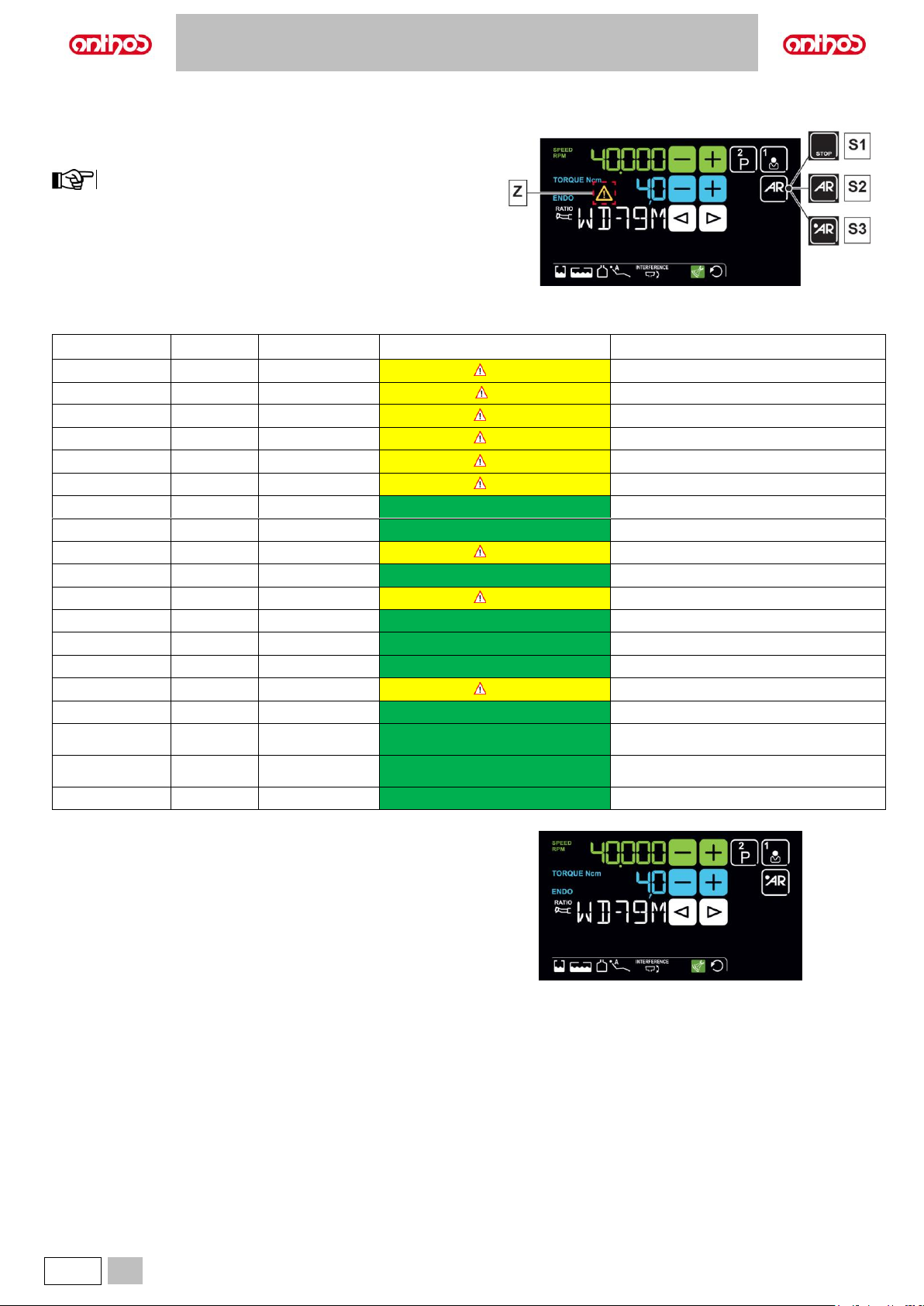
A5 - A6 PLUS - L6
44
EN
Torque value adjustment.
• Set the maximum torque value using buttons (B).
The torque value is expressed in % or Ncm for certified reducers.
The appearance of the symbol (Z) highlights a value reading tolerance of
±20%.
The data set are automatically saved.
Drill rotation at maximum torque.
Select the drill rotation mode when the set maximum torque is reached:
S1 Rotation lock.
S2 Stop normal rotation and reverse rotation.
S3 Stop normal rotation, short reverse rotation and resumption of
normal rotation.
Certified contra angle pre-set list.
Display text
Ratio
Display torque
Torque tolerance to drill
Reference contra angles
128:1
128:1
100%
±20%
All makes
120:1
120:1
100%
±20%
All makes
64:1
64:1
100%
±20%
All makes
40:1
40:1
100%
±20%
All makes
18:1
18:1
100%
±20%
All makes
16:1
16:1
5 Ncm
±20%
All makes
E16
16:1
5 Ncm
±10%
Stern Weber E16®
EVO E16
16:1
5 Ncm
±10%
Goldspeed EVO E16®
10:1
10:1
5 Ncm
±20%
All makes
ER10
10:1
5 Ncm
±10%
NSK ER10®
9.5:1
9.5:1
5 Ncm
±20%
All makes
S6:1
6:1
5 Ncm
±10%
Sirona Endo 6:1
K5.4:1
5.4:1
5 Ncm
±10%
Kavo IntraC 0767 LHC®
EVO E4
4:1
5 Ncm
±10%
Goldspeed EVO E4®
4:1
4:1
5 Ncm
±20%
All makes
ER4
4:1
5 Ncm
±10%
NSK ER4®
K2.7:1
2.7:1
5 Ncm
±10%
Kavo LUX 7LP®
Kavo IntraC 0768 LHC®
WD-79M
2:1
5 Ncm
±10%
W&H WD-79M®
W&H EB-79M®
1:1
1:1
4.5Ncm
±10%
All makes
Menu with micromotor extracted and active.
The following functions can be changed:
• adjust the maximum rotation speed of the drill using the buttons “+” or “”;
Page 45
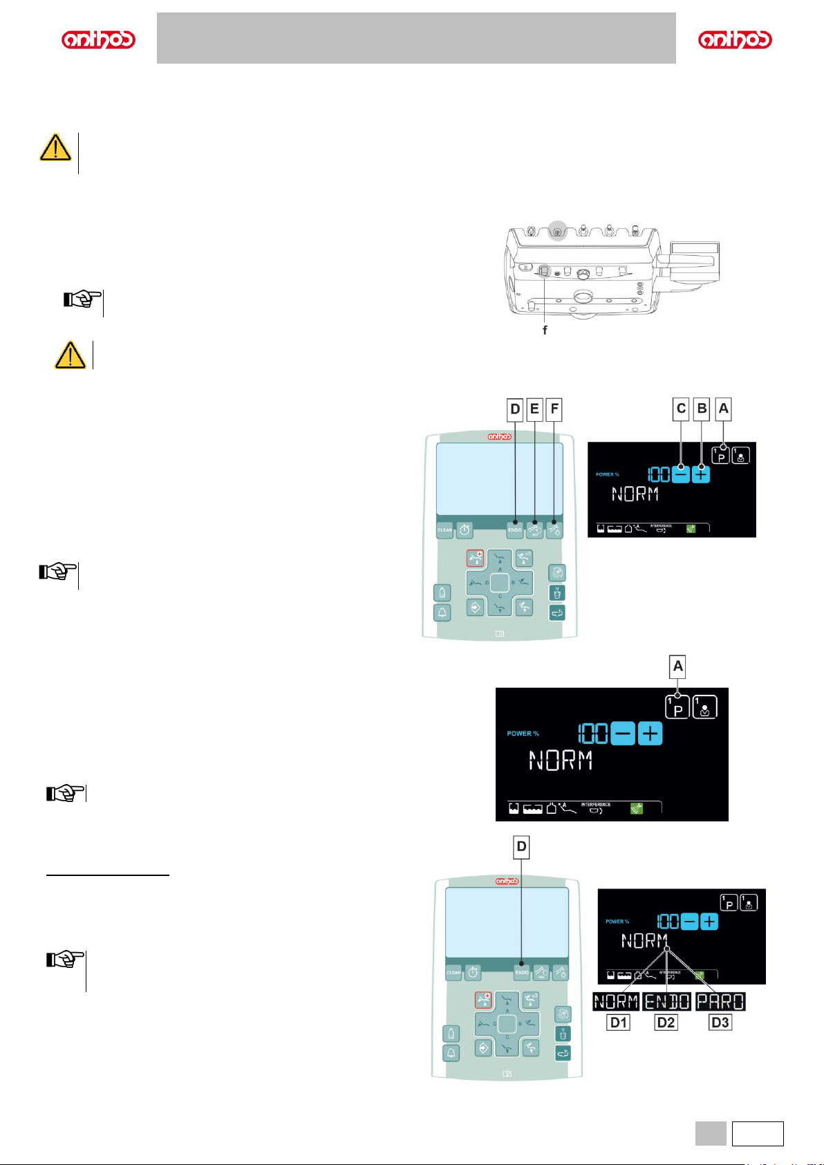
A5 - A6 PLUS - L6
EN
45
5.6. SCALER
Connecting the handpiece and insert.
Refer to the specific instructions provided with the handpiece.
• Before attempting to connect the handpiece, make sure the contacts are perfectly dry. Blow air from the syringe, if necessary, to
dry.
• Make sure the threaded sections of the insert and handpiece are perfectly clean.
Use.
Operating times: see operating instructions supplied with the handpiece.
f Cock that regulates the amount of cooling water
(at the instrument).
• Place the instrument in its work position.
Instrument activation is highlighted by the relevant managing
screen appearing on the DISPLAY.
• Use the foot control lever to start the instrument (see paragraph 5.2.).
The instrument is supplied NON-sterile.
Description of the buttons:
A
Scaler working programme selection.
(for LCD Touch DISPLAY only).
B
Increase the scaler’s power output.
C
Decrease the scaler’s power output.
D
Scaler operating mode selection.
(NORMAL, ENDO or PARO, LCD Touch DISPLAY only).
F
Fiber optics on/off.
Turning on the fiber optics.
Press the button to turn Fiber Optics on/off (F).
The Fiber Optics switch off when the turbine is not used for 30
seconds (rheostat lever disabled).
Scaler working programme selection
(for LCD Touch DISPLAY only).
The scaler has 3 different working programmes, identified with P1, P2 and
P3, that can be selected cyclically.
Each working programme saves the following data:
- maximum power,
- fiber optic on/off,
- type of delivered spray.
Touch the button (A) repeatedly to select the desired programme.
The variation is cyclical.
Scaler operating mode selection
(for LCD Touch DISPLAY only).
With instrument removed
• Select the scaler operating mode by touching the button (D) repeatedly,
the following operating modes will be selected in sequence:
D1 NORM (normal).
D2 ENDO (50% reduced power).
D3 PARO (40% reduced power).
• With the foot control lever activated, you cannot edit operating
mode.
• The data set are automatically saved.
Page 46
A5 - A6 PLUS - L6
46
EN
Removable hose.
Scaler features a removable hose to make cleaning operations easier (see paragraph 5).
Cleaning and maintenance.
Refer to the specific instructions provided with the instrument.
Do not soak the handpiece in disinfectant liquids or detergents.
Sterilization.
Torque wrench, scaler bits and scaler handpiece: steam autoclave up to 135°C following the instructions for the use of the device.
Carefully read the operating instructions supplied with the instrument before attempting to sterilize.
Warnings for use.
• The instrument is supplied NOT STERILE and must be sterilised before use (see paragraph 1.6.).
Carefully read the operating instructions supplied with the instrument before attempting to sterilize.
• For American and Canadian markets only: instruments must be FDA approved.
• Make sure the threaded sections of the insert and handpiece are perfectly clean.
• Do not change the shape of the insert.
• Check wear and tear of the insert on a regular basis, replacing it in the following cases:
- obvious wear,
- drop in performance,
- deformation or impact,
Notes for Sc-a3 scalers:
- class 1 LED apparatus;
- do not direct the light beam in anyone's eyes when cleaning or servicing the device (it is recommended to keep the fiber optics
switched off).
• To avoid hazards or malfunctions when connecting the board, do not reverse the positions of the hoses for scalers of different
brands.
• The inserts fitted on the handpiece must be in compliance with Biocompatibility Standard ISO 10993.
Page 47
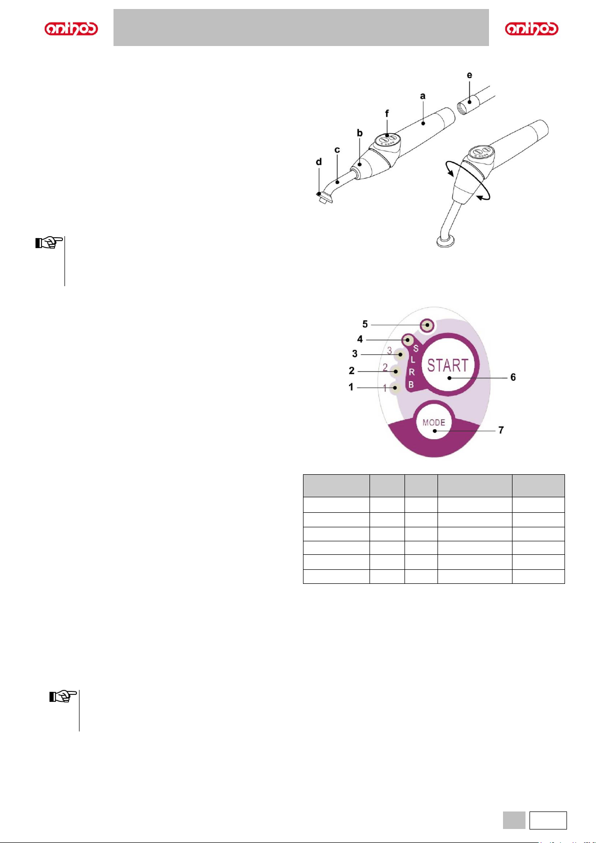
A5 - A6 PLUS - L6
EN
47
5.7. T LED CURING LIGHT
Technical specifications.
Supply voltage: 24-36 Vdc
Max. power absorbed: 6 VA
Light source: 1 5W LED
Wavelength: 430÷490 nm
Acoustic signals: at cycle start, every 5 seconds, and at cycle end
Type of operation: intermittent (work 3 consecutive cycles - rest 60 sec.)
Programs: 6 (preset).
General description of the lamp.
a Lamp handle.
b Rotary end.
c Fiber optic.
d Eye protection.
e Power cord.
f Control panel.
• The curing light can be used in different configurations (wand,
gun or any intermediate position) as it is more convenient for
the user.
• The curing light is delivered in its original packing which should
be kept for future shipment.
Description of the control panel.
1 LED 1 (STANDARD cycle):
Emission of 1000 mW/sq.cm for 20 seconds (this cycle is set as
default at the time of sale).
2 LED 2 (FAST cycle):
Emission of 1600 mW/sq.cm for 15 seconds.
3 LED 3 (STRONG cycle):
Emission of 1800 mW/sq.cm for 20 seconds.
4 LED S:
When LED S is on, you access ramp cycle mode and at the same time
the LEDs next to the letters B, R and L come on:
[LED S + LED 1] ramp cycle B (BONDING):
Ramp cycle with emission of 500 mW/sq.cm for 5 seconds, ramp from
500 to 1000 mW/sq.cm for 5 seconds and 1000 mW/sq.cm for 5
seconds for a total of 15 seconds.
[LED S + LED 2] ramp cycle R (RAPID RESTORATION):
Ramp cycle with emission of 500 mW/sq.cm for 5 seconds, ramp from
500 to 2200 mW/sq.cm for 5 seconds and 2200 mW/sq.cm for 5
seconds for a total of 15 seconds.
[LED S + LED 3] ramp cycle L (LONG RESTORATION):
Ramp cycle with emission of 500 mW/sq.cm for 5 seconds, ramp from
500 to 1800 mW/sq.cm for 5 seconds and 1800 mW/sq.cm for 10
seconds for a total of 20 seconds.
5 Malfunction signalling LED:
This red LED comes on only if there is a malfunction.
6 START button:
Pressing the START button starts the cycle currently selected (the
cycle LED will come on).
If it is pressed again at any time during the cycle, light beam emission
will immediately be interrupted.
7 MODE button:
This button is used to select the cycle to be run. It allows changing
from the current cycle to the immediately following cycle.
The first three cycles (1, 2 and 3) are at constant power and the LEDs
come on individually. When LED S is on, you access ramp cycle mode
and at the same time the LEDs B, R and L come on.
Once the LED of the cycle you intend to use has come on, the lamp
is ready for use. Pressing the START button, light beam emission is
activated according to the selected cycle.
The cycle can be selected and the button is operative only
when the curing light is not emitting any light. If the button is
accidentally pressed while light is being emitted, nothing will
happen.
Cycle
LED
Total
time
Ø8 mm
Total
energy
STANDARD
1
20"
1,000 mW/cm2
20,000 mJ
FAST 2 15"
1,600 mW/cm2
24,000 mJ
STRONG
3
20"
1,800 mW/cm2
36,000 mJ
BONDING
S+1
15"
ramp cycle
11,250 mJ
RAPID REST.
S+2
15"
ramp cycle
20,250 mJ
LONG REST.
S+3
20"
ramp cycle
26,250 mJ
Page 48
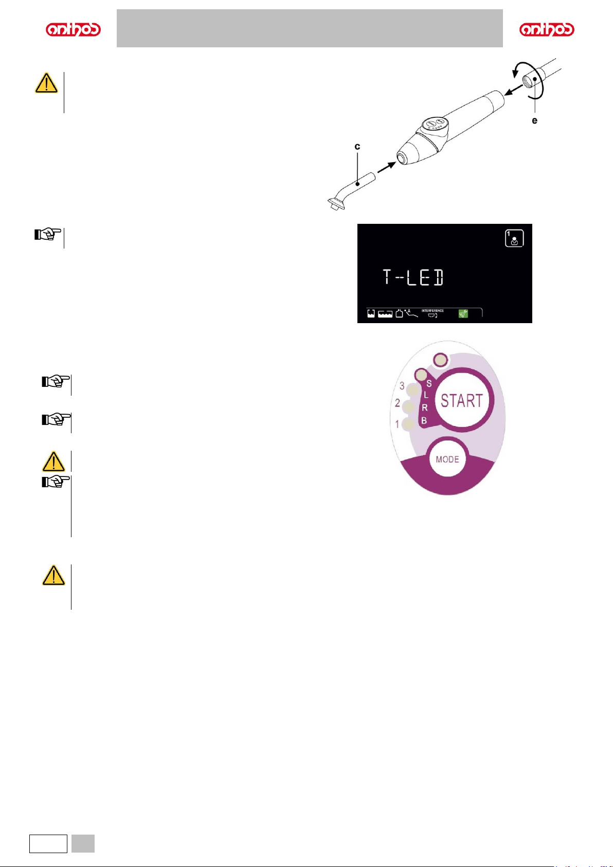
A5 - A6 PLUS - L6
48
EN
Operation.
.
• The instrument is supplied non-sterile.
• Before use, disinfect the lamp handle. The fiber optic and
the eye protection can be sterilized in a steam autoclave
up to 135°C.
• Put the fiber optic (c) in its housing until it clicks.
• Attach the curing light handpiece to the end of its power hose and tighten
the ring nut (e).
• Take the lamp out of its housing on the assistant’s board or dentist's
board.
Instrument activation is highlighted by the relevant managing
screen appearing on the DISPLAY.
• Turn the front of the lamp and/or fiber optic to the position most suitable
for curing (wand, gun or intermediate positions).
• Use the MODE button to select the desired cycle as previously directed
(the selected cycle is always indicated by the illuminated LED).
The curing light has a permanent memory therefore the last
cycle used will always be present the next time it is used.
• Place the fiber optic in the position required for curing.
The fiber optic should be placed as close as possible to the
material to be cured without touching it.
• Press button START to start the cycle.
Operating mode: work 2 consecutive cycles, rest 60
seconds.
When a programmed cycle is activated, the LEDs (1, 2, 3, B,
R, L) indicate the time that elapses (in multiples of 5 seconds)
and turn off every 5 seconds of operation.
The curing light comes with a beep that BEEPS when the cycle
starts, BEEPS every 5 seconds of operation and lastly BEEPS
twice at the end of the work cycle.
• Allow light emission to stop by itself. However, it can be stopped at any
time by simply pressing the START button again.
• The curing light is equipped with a system that signals
malfunctions by illuminating the LEDs in different
combinations (see next paragraph).
• The curing light is equipped with a thermal cut-out.
Page 49
A5 - A6 PLUS - L6
EN
49
Indicators.
The following indicators are provided on the control panel to signal curing light fault:
• LED 5 and LED 1, green, steady on.
Lamp does not emit any light.
Contact technical service department.
• LED 5 and LED 2, green, steady on.
Instrument start up microcontroller fault.
Contact technical service department.
• LED 5 and LED 3, green, steady on.
Power supply too low.
Contact technical service department.
• LED 5 and LED 4 flash continuously.
Handpiece cut-out tripped. These LEDs will continue to flash until the light has cooled down enough (about 5 minutes) to be used again.
If the problem persists, contact technical service department.
Maximum curing thickness.
The maximum curing thickness with every single cycle is 3 millimetres (refer to the instructions of the composite material used as well).
This thickness must not be exceeded as the layer may not be completely cured.
Warnings for use.
The LED is a Class 2 light source in accordance with IEC 62471 standard. DO NOT STARE AT THE BEAM.
The light emitted may cause eye injury in case of direct radiation without eye protection.
Always use an eye protection shield when operating the curing light and do not direct the light beam to the eyes.
The light emitted may damage soft tissues (oral cavity mucous membrane, gums, skin).
Be extremely careful to aim the light precisely on the material to be cured.
• With eye diseases, such as those who have had cataracts removed or retina diseases must be adequately protected when the curing light is
used, for example with suitable protective eyewear.
• The rotary end can turn 180° counter-clockwise in relation to the handpiece to change from wand to gun configuration.
To go back to wand configuration, turn clockwise.
A click is heard when these two positions are reached. Do not turn any more once the click is heard.
The intermediate positions can be used even if a click is not heard.
Put the fiber optic back into the correct position after turning the end section.
• Do not pull the power hoses.
• Do not expose the handpiece to excessive vibrations.
• Do not drop the handpiece and in particular the fiber optic.
The light may break if accidentally hit.
Check the condition of the handpiece if it has been banged or dropped before using the curing light.
Try to turn on the light and check operation first without using it on the patient.
If cracked, broken or if there are any other faults, do not use the curing light on the patient and contact the technical service department.
The fiber optic is rather delicate and may crack or break if banged, affecting the final amount of light emitted.
If dropped, carefully inspect the fiber optic to verify if it is cracked or broken. If cracked, a strong light appears in the spot in which the fiber is cracked.
In all these cases, the fiber optic must be replaced.
• The curing light handpiece (sold separately) can be connected only to dental units with connections for this curing light handpiece.
Connection to any other equipment may damage the circuits inside the lamp and seriously injure the user and patient.
• The curing light handpiece is not protected against liquid penetration.
• The curing light handpiece is not suitable for use in the presence of flammable anaesthetic gas mixed with air, oxygen or nitrous oxide (N2O).
Cleaning.
The curing light may be a means of cross contamination between patients.
The most contaminated parts are the fiber optic and the eye protection. Before sterilizing them, make sure there are no residues of curing products: if
necessary, clean with alcohol or a plastic spatula.
Exclusively sterilise the fiber optic and the eye protection in an autoclave at a sterilization temperature of at least 134°C.
• The fiber optic can undergo 500 autoclave cycles after which it tends to become opaque and therefore emit less light.
• The eye protection must also be replaced after 500 cycles.
• Contact the manufacturer to purchase original spare parts (fiber optic + eye protection: code 97660404).
Page 50

A5 - A6 PLUS - L6
50
EN
The handpiece cannot be put in autoclave; disinfect it on the outside with suitable products and
cover it with disposable plastic wrap.
Use soft disposable paper towels to disinfect the handpiece. Do not use harsh products or soak in liquids.
• The curing light handpiece is NOT suitable for autoclave.
• The curing light handpiece is not protected against penetration of liquids therefore it CANNOT be soaked in a solution to be sterilized.
• The outside of the lamp should be disinfected with the fiber optic on.
Do not use any type of disinfectant on the exposed optical surface of the handpiece when the fiber is removed. The surface will
become irreparably opaque if it comes into contact with disinfectant.
Maintenance.
This equipment does not require any particular type of maintenance.
Only technicians authorised by the manufacturer can replace and/or repair the handpiece and dental unit.
The handpiece has been purposely constructed in a manner that requires specific tools to open it and therefore it cannot be removed by the user.
The warranty is automatically void if the handpiece is altered in any way.
Troubleshooting.
• When the lamp is removed, the light does not come on (no LED on control panel illuminated).
Make sure the Midwest connection is correctly attached to the power hose.
Carefully screw the ring nut, try to put the lamp back in and then take it out again.
If the problem persists, contact technical service department.
• Less light emitted.
- Make sure the fiber optic is not cracked or damaged in any way: replace it if it is so.
Contact the manufacturer to purchase original spare parts.
- Make sure there are no residues of curing products on the end of the fiber optic: if necessary, wipe off with alcohol or a plastic spatula.
If the handpiece must be sent back, please disinfect it.
Ship it back in its original packing.
In addition, please enclose a description of the fault with the shipping note.
Page 51
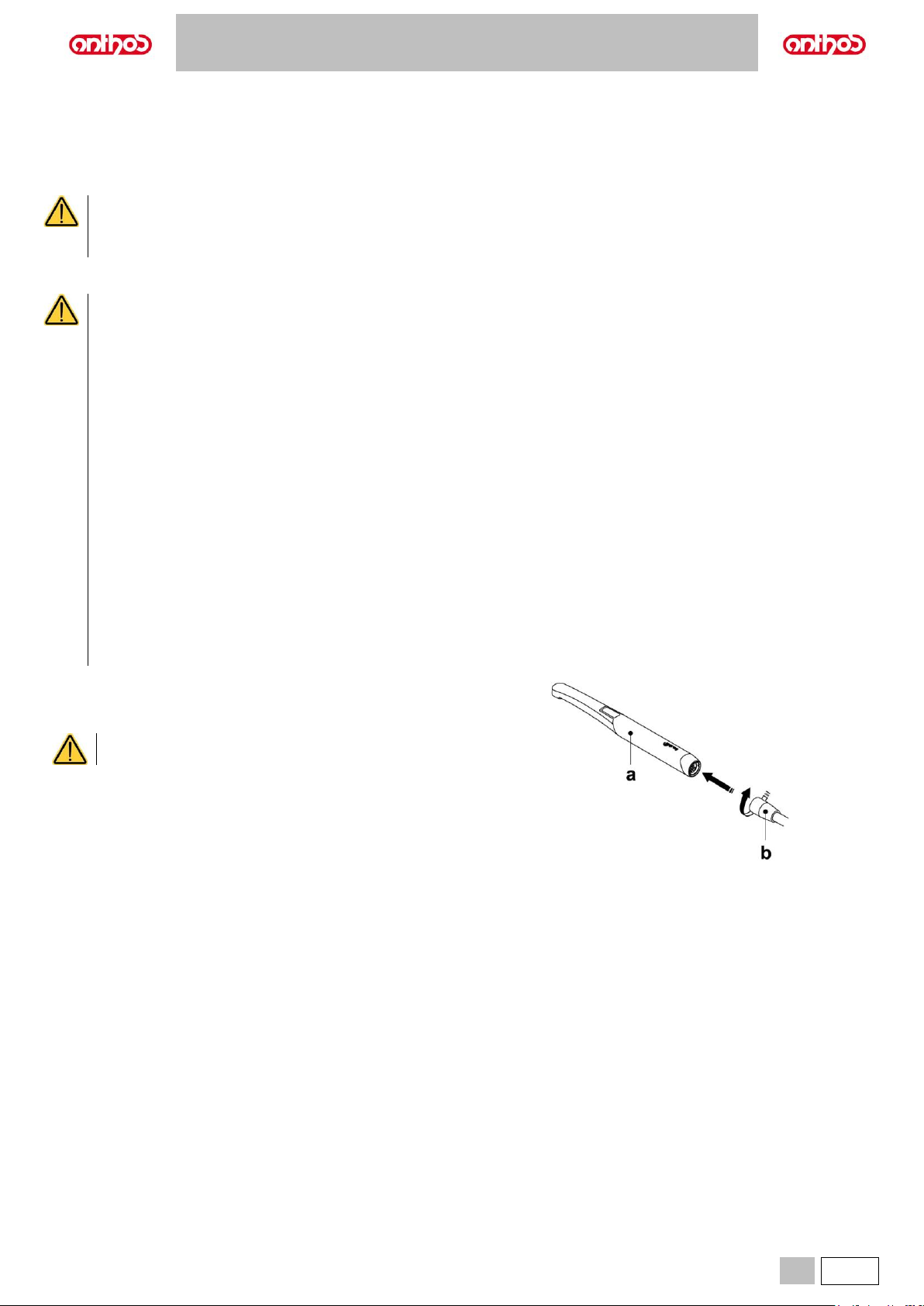
A5 - A6 PLUS - L6
EN
51
5.8. C-U2 DENTAL CAMERA
The C-U2 dental camera system, complete with an extremely lightweight ergonomic handpiece, is specially designed for simple and well-conceived
usability in examining the oral cavity. Auto-exposure and fixed focus features provide easy operation. It is designed to allow the dentist to more efficiently
show and explain to patients all oral conditions and reasons for planned treatment. The C-U2 system allows taking high-definition (1280x720) live images
of the section in question through the touch of a fingertip on the touch-sensitive area of the handpiece. The live intraoral images are displayed on the
monitor or Personal Computer.
The camera may be used as a tool to aid in diagnosis; however, the result must always be supported with visual examination and/or
other diagnostic indications.
Evaluations and conclusions based only on the image taken by the camera may be poor as the colours and shapes, electronically
processed, may not perfectly correspond to the actual ones.
Warnings for use.
• The external PC and the external monitor must be of medical grade, namely they have to be certified and comply with the standard
IEC 60601-1 3rd Ed. They have to be able to ensure a double insulation level for both patient (2 MOPP) and operator (2 MOOP):
- with respect to the power mains;
- to all the I/O ports (USB, LAN) supplied with Safety Extra Low Voltage (SELV).
• It is advisable not to use it in proximity of life support equipment (e.g. pacemakers or heart stimulators) according to the
specifications included in the user manual of such equipment.
• Disposable infection control sheaths must be used with the device and changed for each new patient.
• After putting on a new disposable infection control sheath, check it over before using the camera, making sure it is not torn anywhere.
If it is, take it off and put on a new one.
• Do not place the handpiece in liquids or in autoclave.
• Store the handpiece in a clean dry area.
• Do not bend the connecting cable excessively.
• Be extremely careful not to drop the handpiece and do not expose it to excessive vibrations.
• Never use a damaged handpiece. Make sure the camera is in good condition and has no sharp edges before attempting to use it. If
in doubt, do not use the handpiece, carefully put it away, and contact technical assistance.
• Before starting the equipment, check the condition of the lens protection.
• Do not aim the light beam at the operator’s or patient’s eyes during operation.
• During continuous use (example, more than 10 consecutive minutes), the temperature of the camera’s tip usually increases
significantly; if this is uncomfortable, put the handpiece in its holder for a few minutes to allow the light source to cool down. When
the camera needs to be used for a prolonged time, reduce light brightness using the cursor on the OSD Control Panel (see paragraph
5.8.1.).
• If left running for extended periods, make sure the temperature of the tip is acceptable before attempting to use the camera. Briefly
touch the clear plastic part with your fingertip being careful not to touch the lens in the middle.
• Do not attempt to bend, pull or remove the handpiece.
Connecting the handpiece.
• Attach the handpiece of camera C-U2 (a) to the end of the hose and
tighten the ring nut (b).
Make sure the hose is firmly screwed onto the handpiece.
Page 52
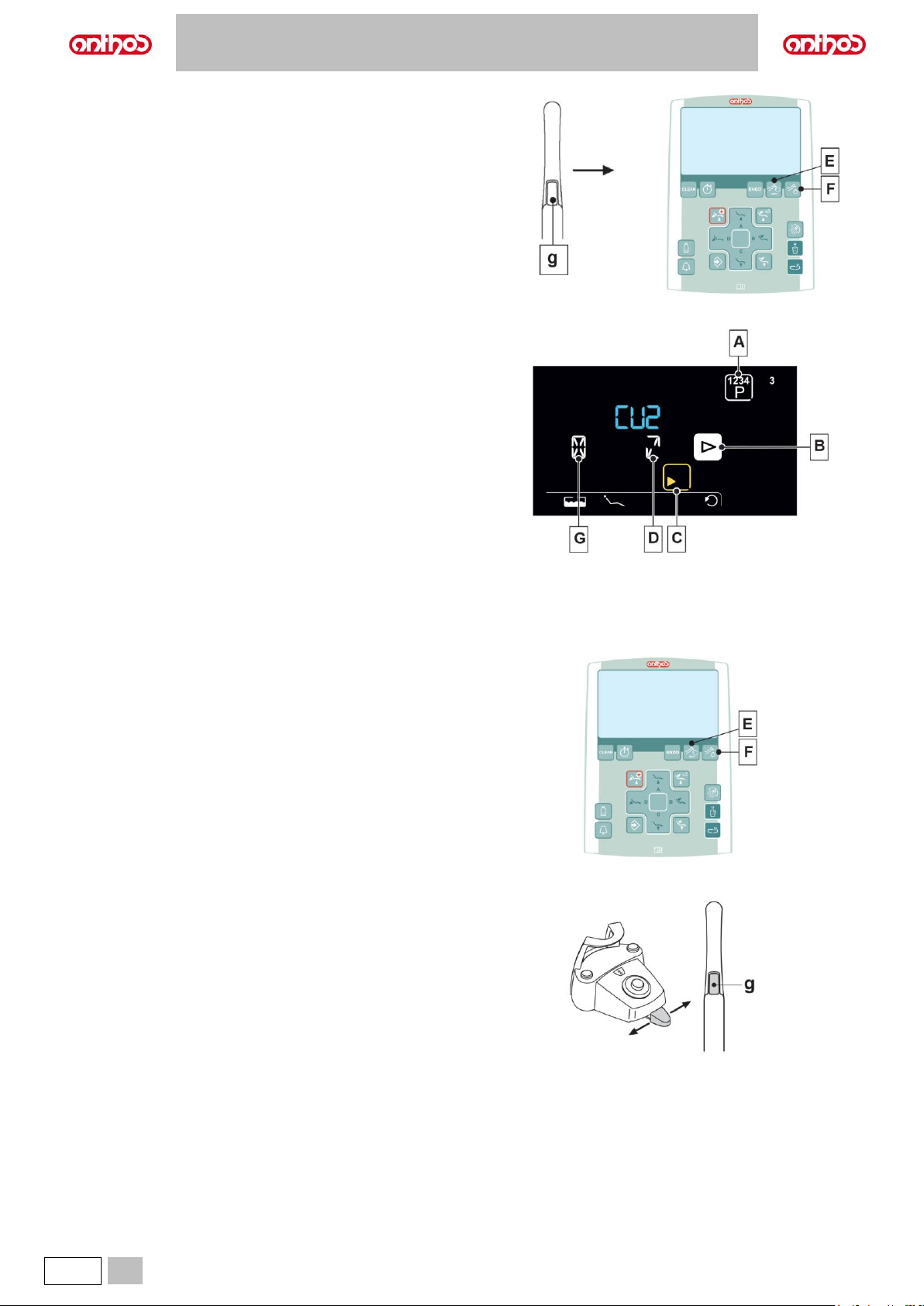
A5 - A6 PLUS - L6
52
EN
Use of the camera.
• Place the instrument in its work position.
Now camera is activated and is in LIVE mode (monitor shows "moving"
images) or FREEZE mode (monitor shows a snapshot).
Buttons on the camera
g
Image acquisition.
Console buttons:
E
Enables/disables MIRROR function
(only with camera extracted and set to LIVE).
F
Turns camera LEDs on/off
(only with camera extracted).
LCD Touch DISPLAY icon buttons:
A
In LIVE mode: allows switching from single to multiple image mode
(and vice versa).
In FREEZE mode: allows scrolling through pages with frozen images.
B
Image selection (scrolling selection).
C
Function to EXIT the image management page.
(camera in FREEZE mode).
D
Enables/disables zoom.
G
Button pressed shortly: deletes selected image.
Button pressed and held: deletes all images.
Image acquisition
• Shortly press the touch key (g) on camera handpiece or operate the foot control to capture the image shown on the monitor.
To go back to "live" image, simply touch again the touch key (g) on camera handpiece or operate the foot control.
• When the camera is set back to LIVE mode, the DISPLAY shows the MAIN PAGE; the image management page remains active in FREEZE mode,
press the touch button (C) to exit it.
Turning on camera lighting system.
• Press the button (F) to turn on/off camera lighting system
MIRROR function.
• With the camera set to LIVE mode, briefly press the button (E) on the
console to change from viewing real images to mirror images.
FREEZE mode.
• Handpiece C-U2 is equipped with a touch-sensitive button (g).
Touch the button (g) (or actuate the foot control) to freeze the image of
interest.
Tap the button (g) again (or actuate the foot control) to unlock the frozen
image.
Page 53
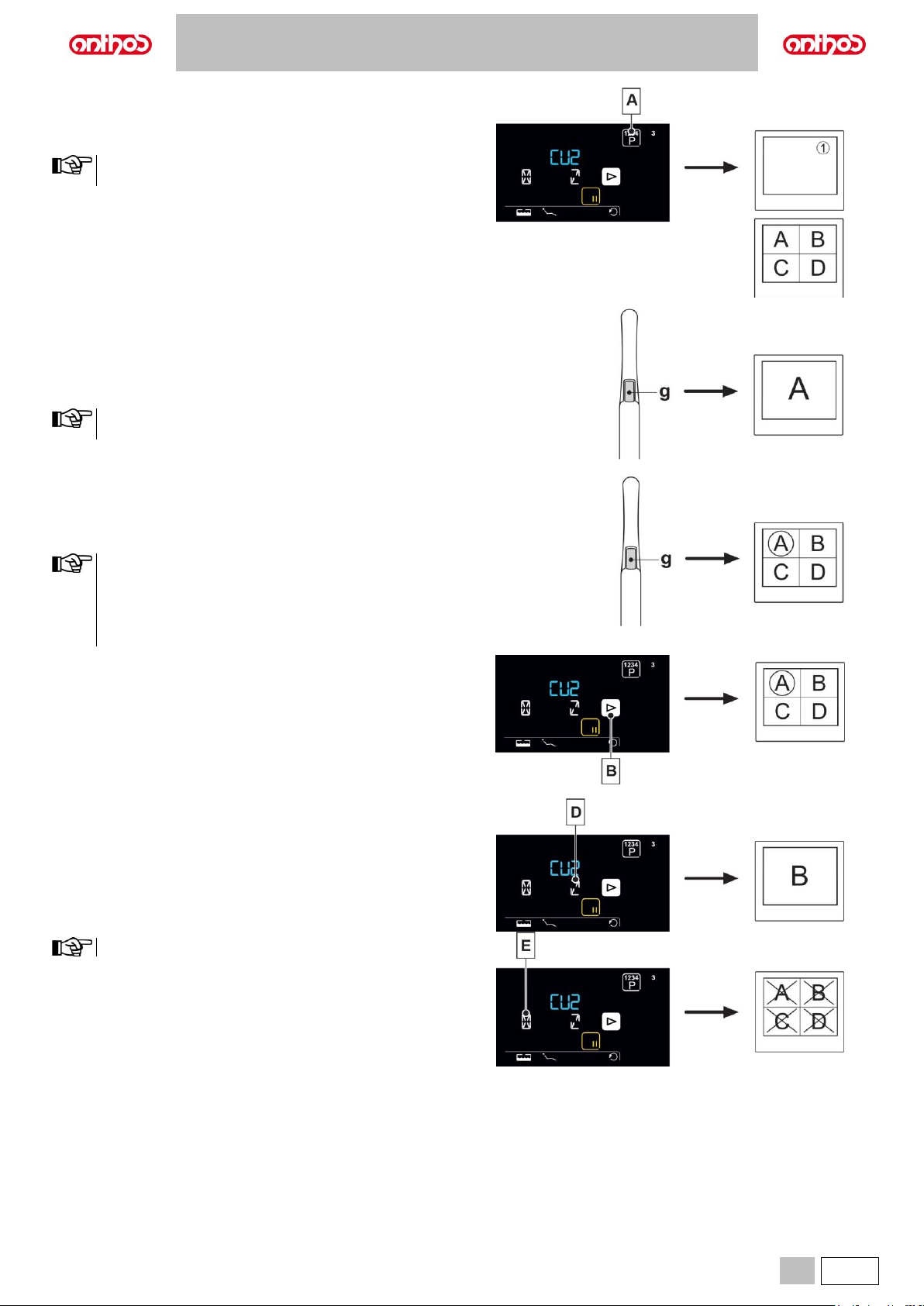
A5 - A6 PLUS - L6
EN
53
Setting operation in single image or multiple image mode (LCD
Touch DISPLAY only).
• With the camera set to LIVE mode, briefly press the button (A) to change
from viewing a single image to multiple images (and vice versa).
A dedicated icon, found in the top right-hand corner, signals on
the monitor when single-image mode is active.
Operation in single image mode.
• The "live" image appears on the monitor and a special icon (1) is shown
in the top right-hand corner when the camera is set to LIVE and singleimage mode.
By pressing the touch button (g) on the handpiece (or by activating the
foot control), you can freeze the image, which is immediately shown on
the monitor deleting any other previous image.
The last frozen image remains on the monitor even if the camera
is put back in place.
Operation in multiple image mode.
• The "live" image appears on the monitor when the camera is set to LIVE
and multiple image mode.
Pressing the touch button (g) on the handpiece (or activating the foot
control), you can freeze the image, which is immediately shown on the
monitor.
The frozen image appears directly on the monitor in the first box
available on the page currently displayed. Any following frozen
image is then positioned in the following box in reading order.
Once the 4 available boxes have been filled, each following
frozen image will replace the existing ones appearing always in
reading order.
• With the camera in FREEZE mode, by pressing the button (B) or by
activating the CHIP-AIR command using the foot control (see paragraph
5.2), you can select the stored images in rotation.
• With the camera in FREEZE mode, pressing the button (D) you can
enable/disable the full screen display of the selected image.
Press the button (E) for at least 3 seconds to delete all images.
VIEW function.
• With the camera in FREEZE mode, by pressing the touch button (A)
repeatedly, you can scroll down the pages with frozen images.
Page 54
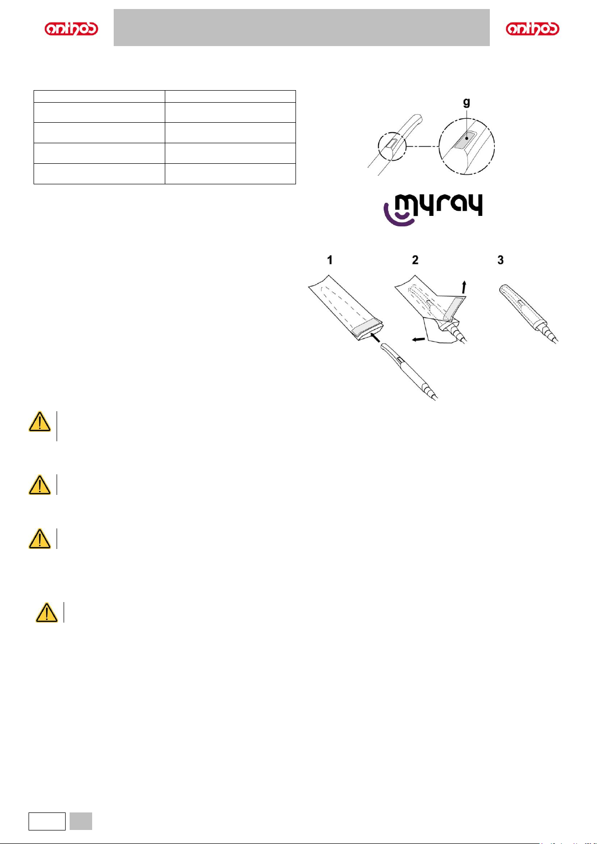
A5 - A6 PLUS - L6
54
EN
Handpiece status
An optical guide, illuminated by a multicolour LED indicator, found in the area near the control button (g), shows handpiece status as per the table given
below:
Colour
Situation
Blue light flashes, very slowly
Handpiece in standby
Light blue steady light
Handpiece activated, live images
displayed
Blue/ light blue flashing light
Handpiece in image freeze mode
Brief red flashes
Internal error: contact Technical
Service
MyRay iCapture.
This programme allows the C-U2 camera to be set up when it is connected
to a PC/WORKSTATION.
For a full description on how the MyRay iCapture programme works, refer
to the instructions, in electronic format, supplied with the C-U2 handpiece.
Disposable infection control sheaths.
The camera can be a source of cross-contamination between patients.
For this reason always use it with a disposable infection control sheath
(code 97901590) and disinfect it on the outside after use every day.
The sheath (with white paper backing) is enclosed in two protective layers:
a transparent one with blue tab at the front and a paper one at the back.
Follow the directions below to install a new disposable infection control
sheath:
• Insert the camera handpiece tip between the layer with white tab and
the rear paper backing. The lens, surrounded by the LEDS, must face
down, towards the rear paper layer. Gently push the handpiece to the
end of the sheath.
• Pull the blue tab removing the protective covers.
• The dental camera is now protected and ready for use.
• Always make certain the handpiece is correctly inserted inside the infection control sheath.
• To ensure user and patient safety, always change the disposable infection control sheath before using the device on a new patient.
• Disposal: the disposable infection control sheaths are to be treated as special waste materials (like surgical gloves).
Cleaning and disinfection.
Clean the handpiece with a suitable product after each use: refer to paragraph 1.5.
• The camera is not designed for cold immersion sterilization.
• All products must be used as directed by the manufacturer.
Maintenance and repairs.
The C-U2 dental camera does not require any particular maintenance. In the event of malfunctions, please send back the complete handpiece.
There are no parts that can be repaired on site. In the event of a malfunction, please contact an authorised dealer.
Returning parts.
• Please send back any defective devices in their original packaging. Do not reuse damaged boxes.
• The device must be disinfected before being shipped to prevent cross-contamination. Handpieces that have not been adequately cleaned and disinfected
will not be accepted.
The sender shall be held responsible for any equipment damage occurred during shipment regardless of whether or not the devices
are under warranty.
Page 55
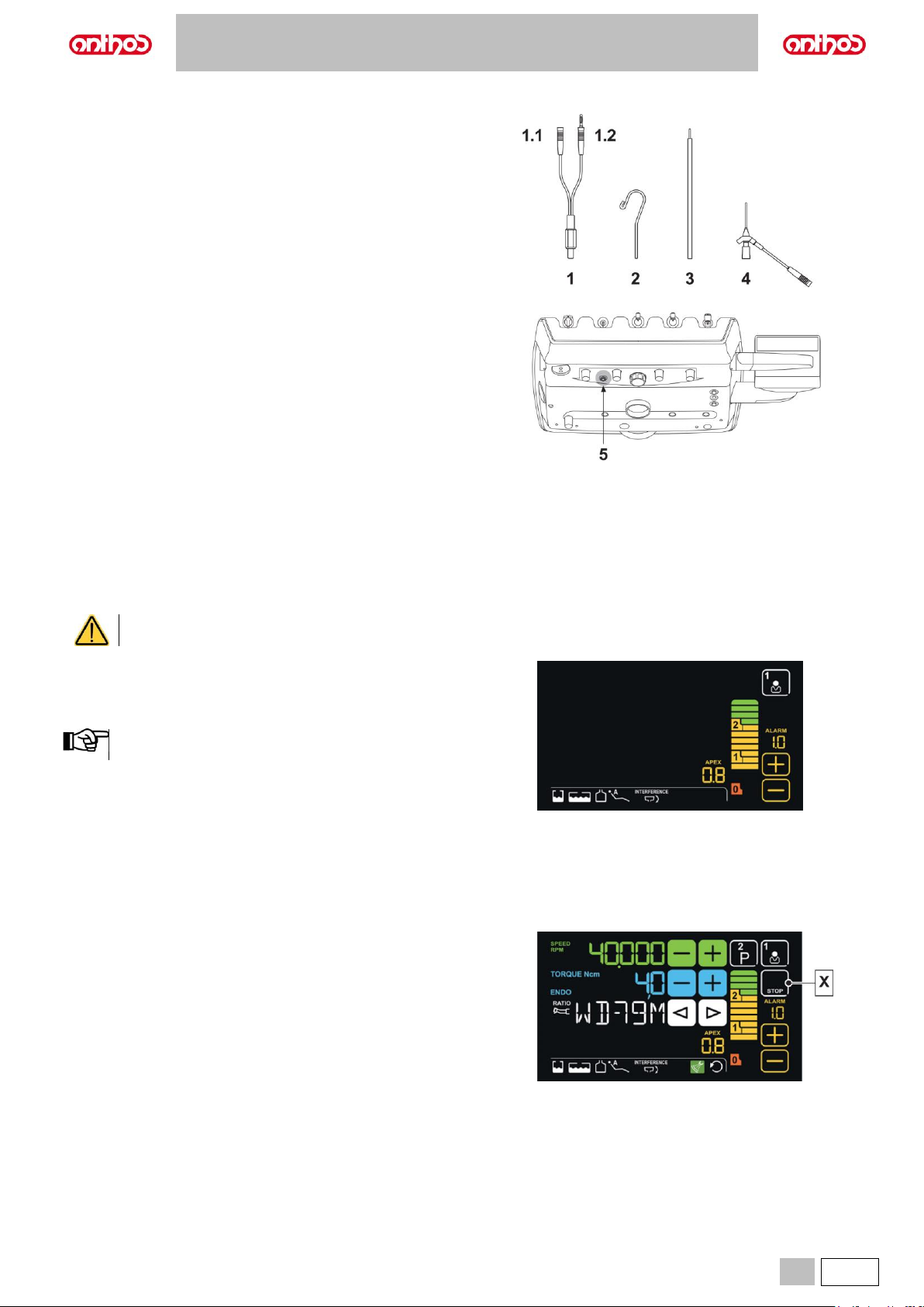
A5 - A6 PLUS - L6
EN
55
5.9. ELECTRONIC APEX LOCATOR
This locator, through the analysis of the variations of special electric
signals, makes root apex location easier. If used together with a "file" (not
supplied) for manual treatment, it proves useful also to measure canal
length.
In addition to being used for manual detection with external wiring, the
locator can also perform live detection during root canal treatment. With
micromotor in ENDODONTIC mode and with suitable contra angles, the
locator uses the same file inserted in the canal as the active detection
probe.
Component description.
1 APEX LOCATOR external wiring.
1.1 APEX LOCATOR external wiring - neutral pole.
1.2 APEX LOCATOR external wiring - active pole.
2 Hook-type electrode.
3 Probe.
4 APEX LOCATOR clip connecting tweezers.
5 APEX LOCATOR external wiring port.
Operation.
• On this dental unit, the locator is automatically activated upon external
wiring (1) insertion inside the special socket (5) positioned under
dentist's board.
Once enabled, the menu for trigger threshold setting appears on the
DISPLAY (see paragraph 5.1.1.17.).
• Electrode application:
- Connect hook-type electrode (2) to neutral pole (1.1) and position it
on patient's lip.
- Connect active pole (1.2) to file (not supplied) inserted inside the root
canal; connection to the file can be carried out through probe (3) or
through the special tweezers (4) or directly from the file inserted in the
canal through special handpieces.
Electrodes are supplied NON-sterile.
Indications on LCD Touch DISPLAY.
• The bargraph on DISPLAY right-hand side indicates file position
compared to apex. The numerical indications “1, 2" refer to the relative
distance between instrument and apex.
The indication "> 3" signals that the file is too far from apex to
be detected.
• The APEX icon displays the set trigger threshold.
The trigger threshold refers to the distance between instrument and
apex above which an audible signal - progressively increasing as
instrument gets closer to apex - is generated.
Set the time using the touch buttons "+" and "-".
Both graphic and numerical indications are constantly updated while file
is inserted inside canal.
APEX LOCATOR combined with electric micromotor.
This locator can also be used in combination with the electric micromotor
when set to ENDO mode.
When the locator is enabled, if electric micromotor is extracted in ENDO
mode both the information relating to the micromotor and those relating to
locator (bargraph and APEX values) are shown at the same time on the
DISPLAY.
During electric micromotor operation, the keys are associated to
instrument functions, and locator trigger threshold cannot be edited but by
putting instrument back in place.
X APEX STOP enabled
Page 56
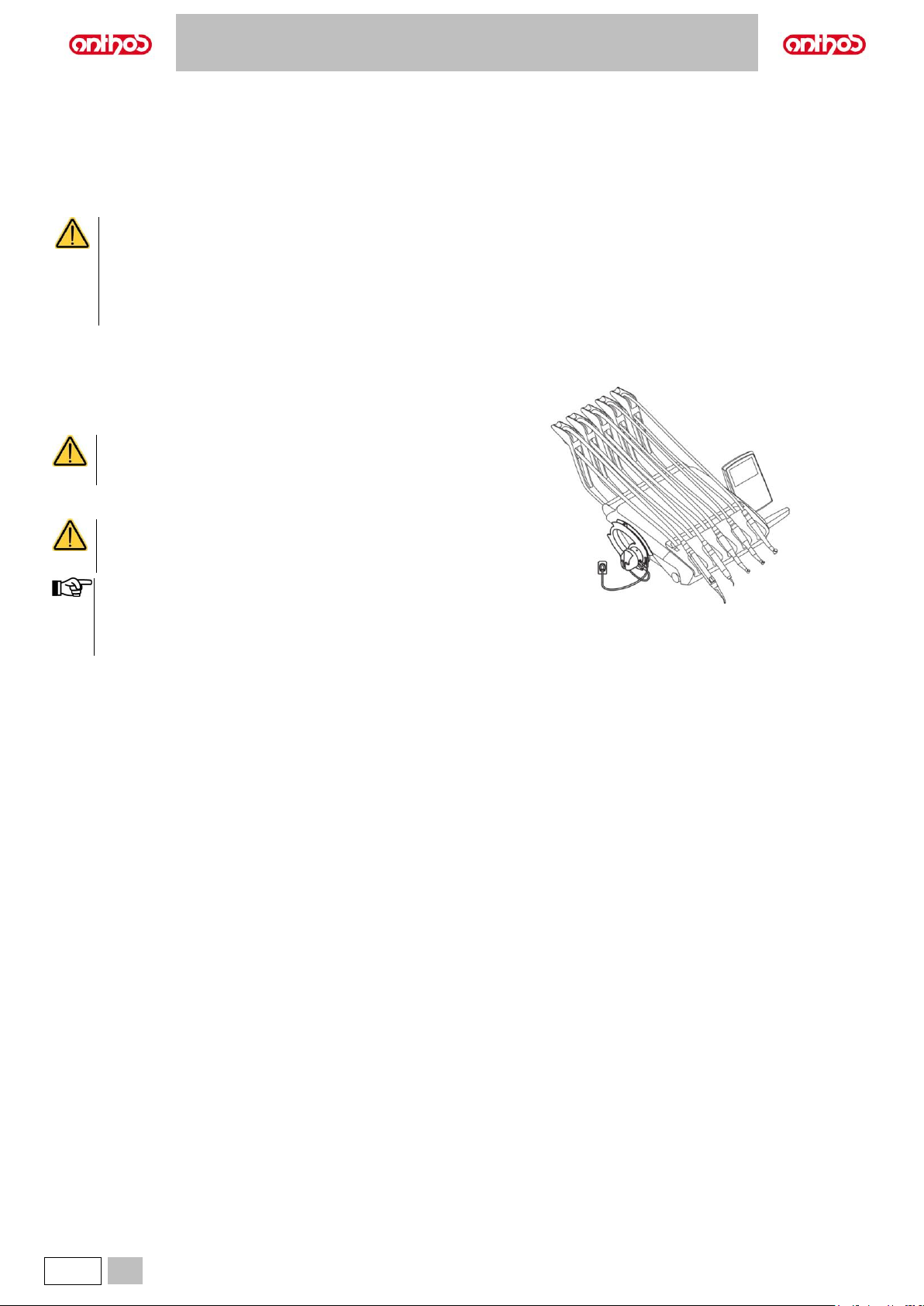
A5 - A6 PLUS - L6
56
EN
Root canal length detection.
• The use of manual file is of the utmost importance for canal detection. The correct procedure entails file insertion inside canal until reaching indication
0.5.
• Insert the file with a slow clockwise rotation until the APEX indication appears on the instrument.
• Once APEX indication appears, move the file backward by turning it counter-clockwise until reaching again the value of 0.5. Position a rubber stopper
close to the occlusal surface as a reference point to define the work length inside root canal.
• Make an X-ray to check file correct positioning.
• Remove file from canal and measure the work length with a ruler. Deduct a safety value of 0.5-1 mm from the reading.
Always use the locator in combination with X-ray test to accurately define apex position.
Different, and not always predictable, morphological conditions could lead to inaccurate readings.
For example:
- Excessively wide root canal.
- Re-treatments.
- Broken roots.
- Presence of metal crowns.
5.10. ZEN-Xi INTEGRATED SENSOR
The integrated ZEN-Xi sensor is a medical device used for the acquisition
of intraoral X-rays in electronic format through the interface with a
Personal Computer.
Do not use the system for tasks other than the acquisition
of intraoral X-rays, and do not use it if you are not an expert
in dentistry and radiology.
Use
ZEN-Xi integrated sensor instructions for use are included
with the equipment, please read carefully the warnings for
use before turning sensor on.
• The integrated ZEN-Xi sensor has no electrical interaction with
the dental unit.
• For L6 CONTINENTAL model, HYBRID version:
the application of ZEN-Xi integrated sensor excludes the
possibility to reverse the console unit position.
Page 57
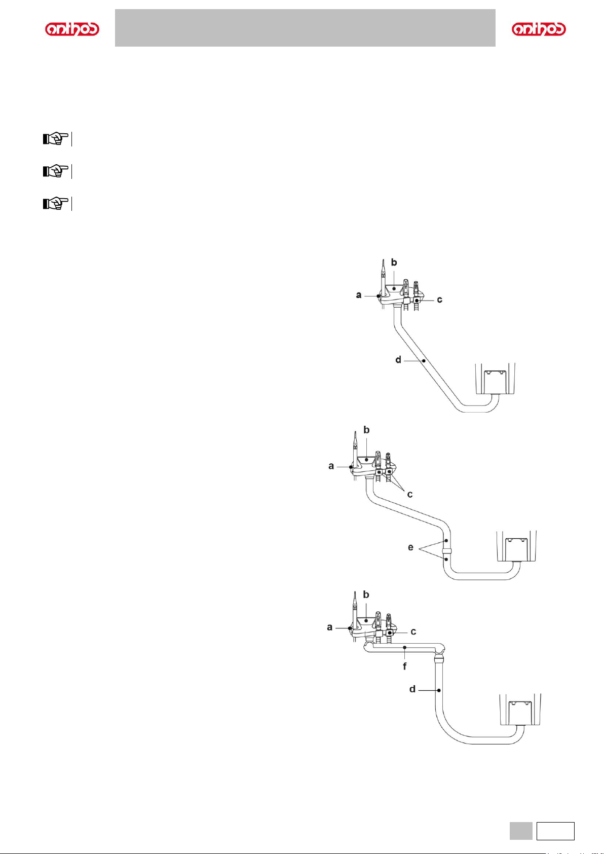
A5 - A6 PLUS - L6
EN
57
6. ASSISTANT’S BOARD OPERATION
Description of the parts.
a Assistant’s board: it can hold 2 suction tubes and 3 instruments, of which 1 is dynamic.
b Control panel used to operate the dental chair and water unit.
c Guides with sliding rollers that hold up the hoses of the suction tubes.
d Articulated arm allowing positioning the assistant’s board in the area most convenient for the operator.
The arm is equipped with a safety device that stops dental chair movement as soon as it detects an obstacle.
e Pair of articulated arms allowing positioning the assistant’s board in the area most convenient for the operator.
The two arms are equipped with a safety device that stops dental chair movement as soon as it detects an obstacle.
f Pantograph arm with six work positions, allowing a vertical stroke of the assistant's board of 300 mm.
To move the pantograph arm back to the fully lowered position, lift it until reaching the end of travel and then lower it.
g Clutched pantograph arm, with vertical stroke of the assistant's board of 300 mm.
h SINGLE WATER UNIT assistant’s board: it can hold 2 suction tubes and 3 instruments, of which 2 are dynamic.
i SINGLE WATER UNIT control panel to control the functions of dental chair, water unit and the instruments housed on the assistant’s board.
Dental units model:
A5 CONTINENTAL
A5 INTERNATIONAL
A5 CART
A5 SINGLE WATER UNIT
Page 58
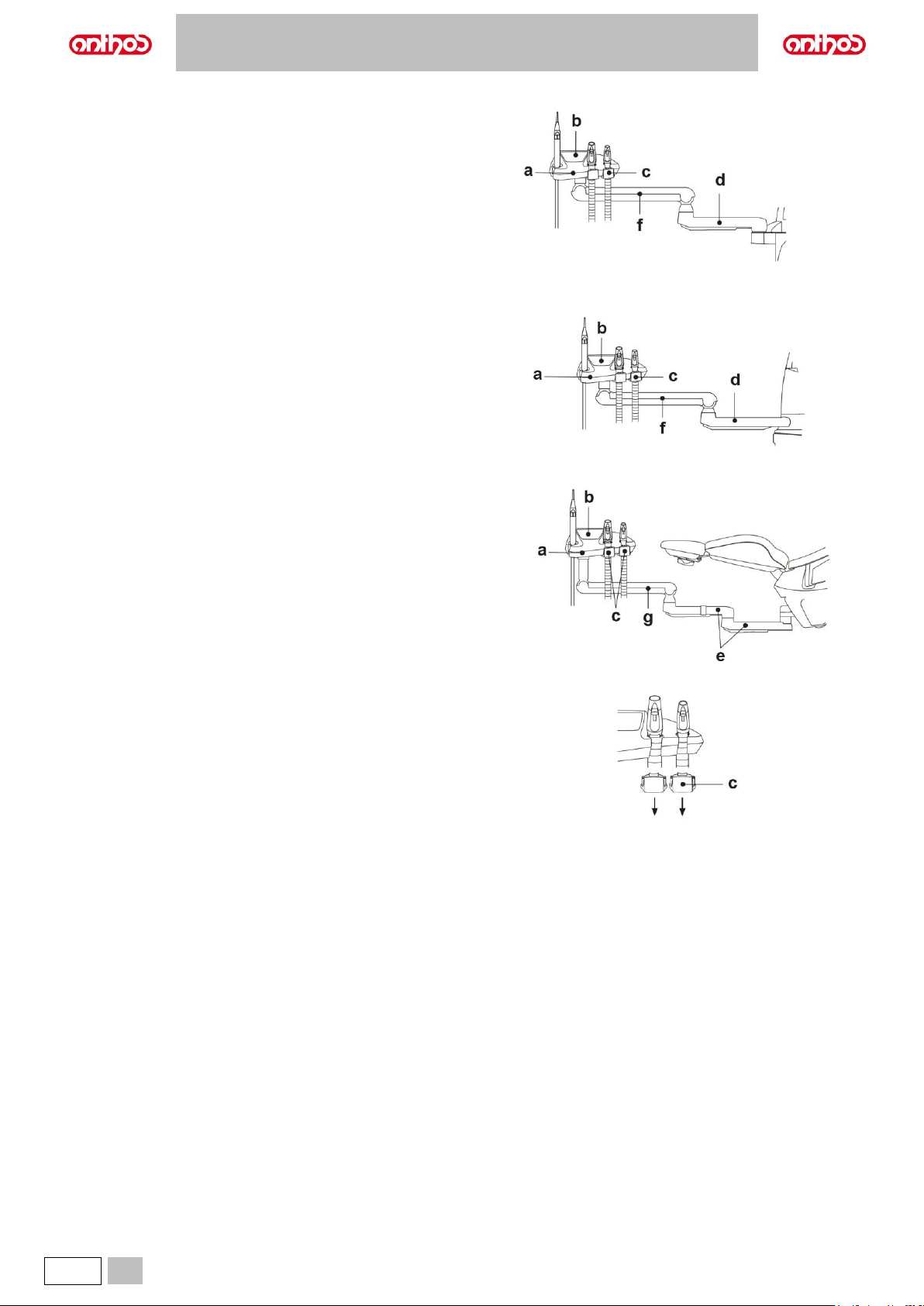
A5 - A6 PLUS - L6
58
EN
Dental units model:
A6 PLUS CONTINENTAL,
A6 PLUS INTERNATIONAL
Dental units model:
L6 CONTINENTAL
L6 SIDE DELIVERY
Dental units model:
L6 CONTINENTAL, HYBRID version
Cleaning the sliding rollers.
Push down and take off the sliding rollers (c).
Clean the sliding rollers with a suitable product: refer to paragraph 1.5.
Page 59
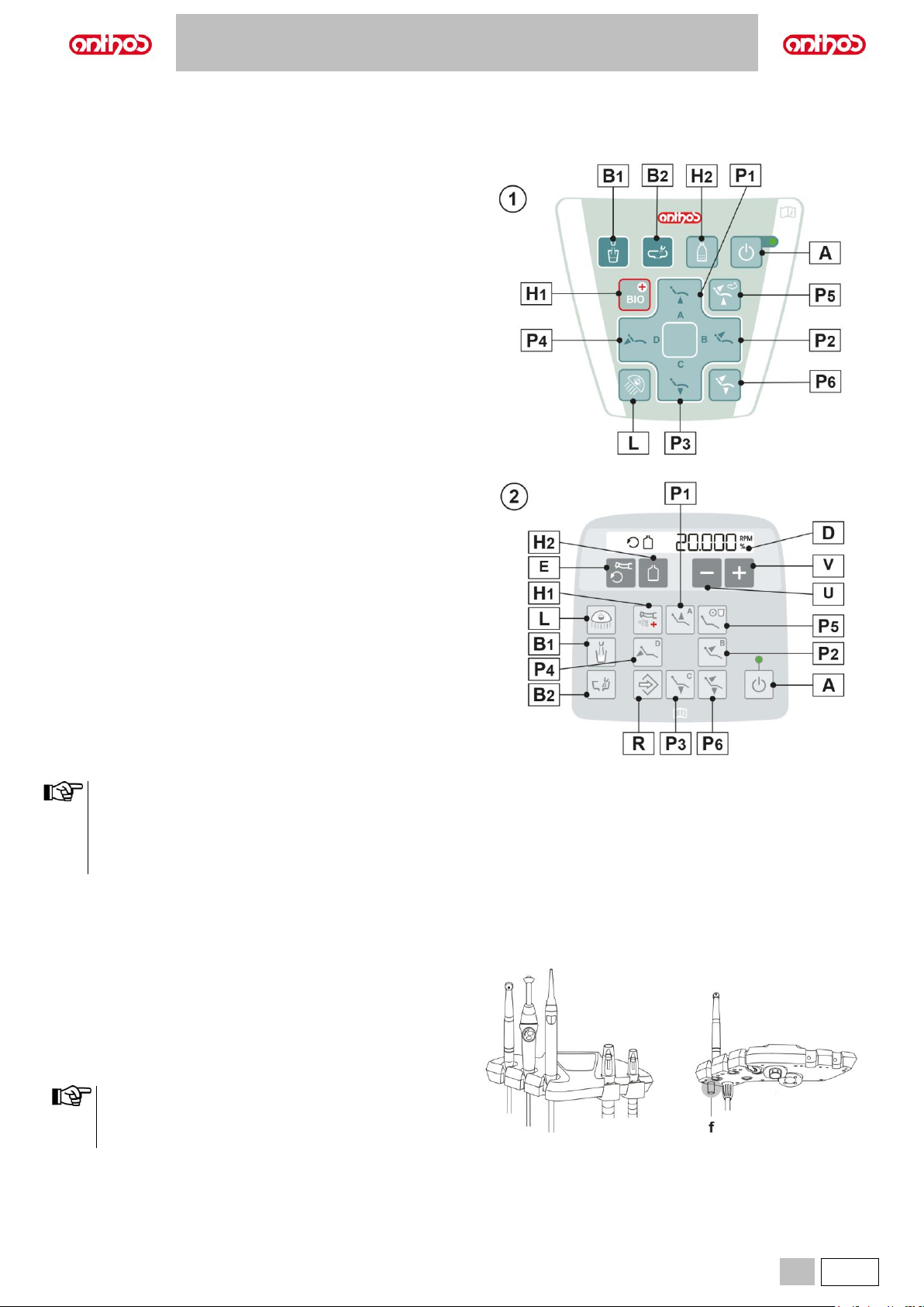
A5 - A6 PLUS - L6
EN
59
6.1. ASSISTANT’S BOARD CONSOLE
1 Standard version.
2 SINGLE WATER UNIT model version.
Description of the buttons:
A
Dental unit POWER SAVING button
(with relevant warning LED)
L
Operating light on/off button
B1
Water-to-cup button
B2
Water-to-bowl button
P1
Seat up and programmed position A recall button
P2
Backrest up and programmed position B recall button
P3
Seat down and programmed position C recall button
P4
Backrest down and emergency position D recall button
P5
Rinse position recall button
P6
Reset position recall button
H1
Fast activation button for BIOSTER S / FLUSHING cycles
H2
S.H.S. system enabling/disabling button
U
Decreases settable values.
V
Increases settable values.
E
Reversing micromotor drill rotation direction.
R
Enabling dental chair position storage.
D
Digit DISPLAY
Operation of dental chair buttons:
• Button pressed shortly: automatic recall of set position.
• Button pressed and held: manual positioning.
Operation of hygiene cycle activation button (H1):
• Button pressed shortly: FLUSHING cycle activation.
• Button pressed and held: BIOSTER S cycle activation.
6.2. INSTRUMENTS ON ASSISTANT’S BOARD
All the instruments applied to the assistant's board maintain the same
operation as those on the dentist's board.
In particular:
• Syringe, see paragraph 5.3.
• Turbine, see paragraph 5.4.
• Micromotor, see paragraph 5.5.
• Scaler, see paragraph 5.6.
• Curing light, see paragraph 5.7.
• Camera, see paragraph 5.8.
The turbine, micromotor and scaler have a cock (f) for adjusting
the spray water, under the assistant's board.
It is not possible to adjust the amount of spray air in the turbine
and micromotor.
Page 60
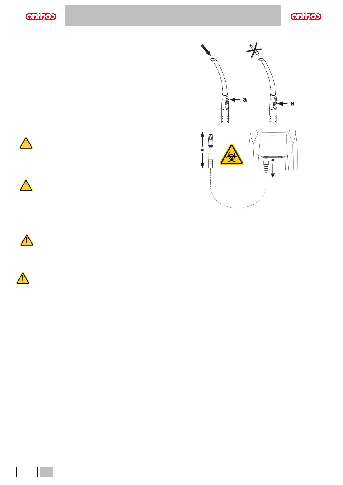
A5 - A6 PLUS - L6
60
EN
6.3. SUCTION TUBES
Suction starts when lifting the suction tube holder off its support.
To adjust suction power, use the lever (a) located on the suction tube
holder handle.
The dental unit is equipped with the V.D.S. system that allows the drying
of the suction line using an automatic stop delay (about 2 seconds).
For flushing procedure, see paragraph 7.6.
Removing the suction tubes.
Always wear goggles and gloves to prevent contact with
infected material when removing the suction tubes.
Remove the suction tubes from the conveyor fittings by turning and pulling
the tube fitting.
Detach the suction tubes from the holders by turning and pulling the tube
fitting.
Never directly grasp the suction tube.
Sterilization.
• Suction tube holder terminals: steam autoclave up to 135° C following the instructions for the use of the device.
• Suction tubes: soak to cold-sterilize.
With the tubes, never use procedures where temperature exceeds 55° C.
Flushing the suction tubes
As the dental units may be equipped with different suction systems (liquid or wet ring, air) carefully follow the instructions provided by the suction system
manufacturer when disinfecting the system regarding the product to be used, times and directions for use.
For cleaning of the suction system, it is recommended to use STER 3 PLUS (CEFLA s.c.) diluted in a 6% solution (equivalent to 60 ml
of product in 1 litre of water).
Maintenance.
Periodically lubricate the O-rings of the suction tube holder terminals (see Paragraph 9.4.) using S1-Protective Lubricant for O-Rings (CEFLA s.c.).
Note about biocompatibility.
Only use suction tubes supplied with the dental unit and original spare tubes.
The suction tubes must comply with Biocompatibility Standard ISO 10993.
ISOLITE suction tube.
For ISOLITE suction tube operation, please refer to the specific use instructions given by the manufacturer.
Page 61
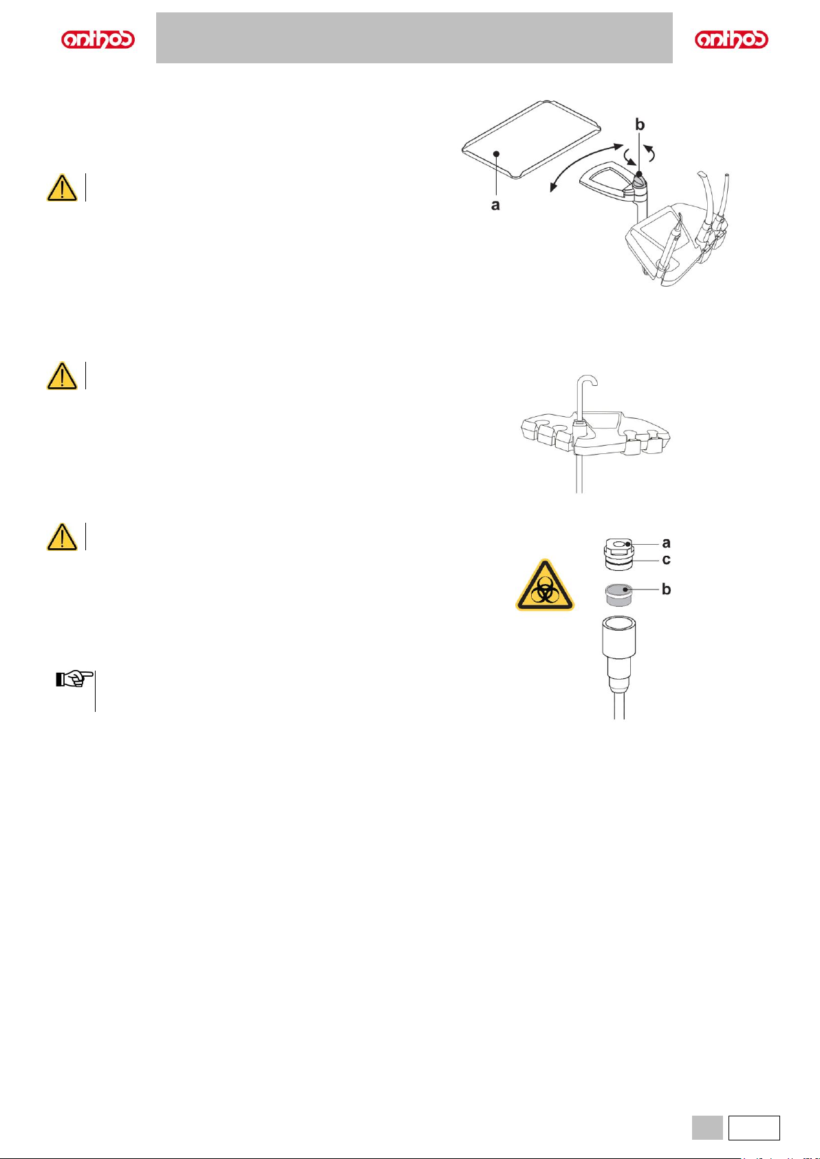
A5 - A6 PLUS - L6
EN
61
6.4. TRAY HOLDER
The tray holder (a) is made of stainless steel and can easily be removed
from its support.
Tray holder support can rotate both clockwise and counter-clockwise, so
as to be positioned in the most convenient position for the operator.
To lock/unlock the tray holder support, simply turn the clutch knob (b).
Maximum permitted load on the tray holder: 1 kg distributed.
6.5. HYDRAULIC SALIVA EJECTOR
Warnings for use.
The dental unit equipped with hydraulic saliva ejector does
not comply with standard EN 1717.
The hydraulic saliva ejector starts running when the tube is removed from
the support.
Cleaning after each use.
Aspirate about ½ litre of STER 3 PLUS (CEFLA s.c.) diluted in a 6%
solution (equivalent to 60 ml of product in 1 litre of water).
Cleaning the saliva ejector filter.
This operation must be carried out at the end of each work day.
Wear gloves before attempting to perform this operation!
• Suck about ½ litre of STER 3 PLUS diluted in a 6% solution (equivalent
to 60 ml of product in 1 litre of water).
• In order to prevent possible dripping of liquids and matter from the filter
(b) to be extracted, suck only air for about 5 seconds.
• Take off the cap (a) by turning and pulling at the same time.
• Remove the filter (b).
• Clean/replace the filter (code 97290060).
• Put the filter and cap back in place.
To prevent liquids and matter from dripping from the filter taken
out, suck air only for approximately 5 seconds before
performing these operations.
Routine maintenance.
Lubricate the O-Ring (c) with S1-Protective Lubricant for O-Rings.
Page 62
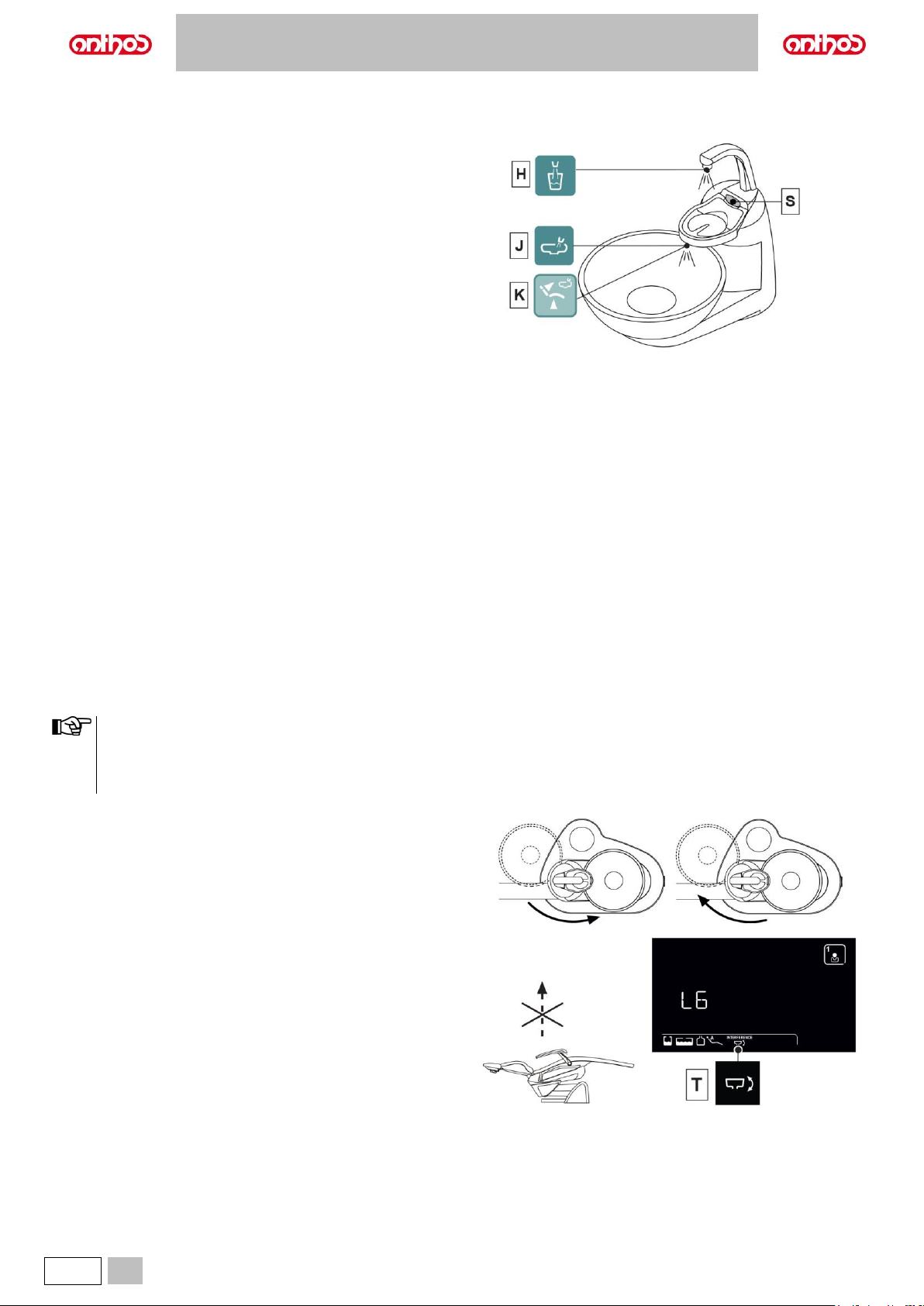
A5 - A6 PLUS - L6
62
EN
7. WATER UNIT OPERATION
7.1. FILL CUP AND BOWL
The bowl can be turned 305° on the water unit by hand or using a motor
drive (optional).
The bowl and the water-to-cup spout can be removed to make cleaning
operations easier.
Control buttons.
H Water-to-cup delivery control button.
J Water-to-bowl delivery control button.
Bowl flushing automatically stops after 30 seconds.
Bowl washing automatically starts in the following cases:
• When the rinse position button (K) is pressed.
• When the water-to-cup delivery button (H) is pressed.
Hot water to cup.
When this function is provided, hot water is always delivered to the cup.
Cup sensor (S) (optional).
An optical sensor detecting cup presence and automatically enabling cup
filling can be installed under cup spout.
Operation:
• when the cup is placed under the spout, water delivery starts after 2
seconds for the duration set,
• once cup is removed, the automatic filling can be repeated after 3
seconds,
• during filling, by removing cup, water delivery is immediately interrupted,
• to disable cup sensor, call the Technical Service.
Motor-driven bowl automatic movements
Bowl automatically moves:
• When "Dental chair rinse position" button is pressed.
• When "Dental chair reset position" button is pressed.
Motor-driven bowl safety device
(dental units of L6 series only).
The bowl is equipped with a safety device that automatically moves it out
of the interference area with the dental chair.
If the bowl finds an obstacle that prevents it from moving out of
the interference area, a second safety device will block the
automatic movement of the dental chair.
The block is signalled by a double BEEP and by the flashing icon
(T) appearing on the LCD Touch DISPLAY.
Manual bowl safety device
(dental units of L6 series only).
The bowl is equipped with a safety device preventing the dental chair to
move up over a certain height when the bowl is positioned in the
interference area.
The block is signalled by a double BEEP and by the flashing icon (T)
appearing on the console display.
To remove the block just turn the bowl outside of the interference area.
Page 63
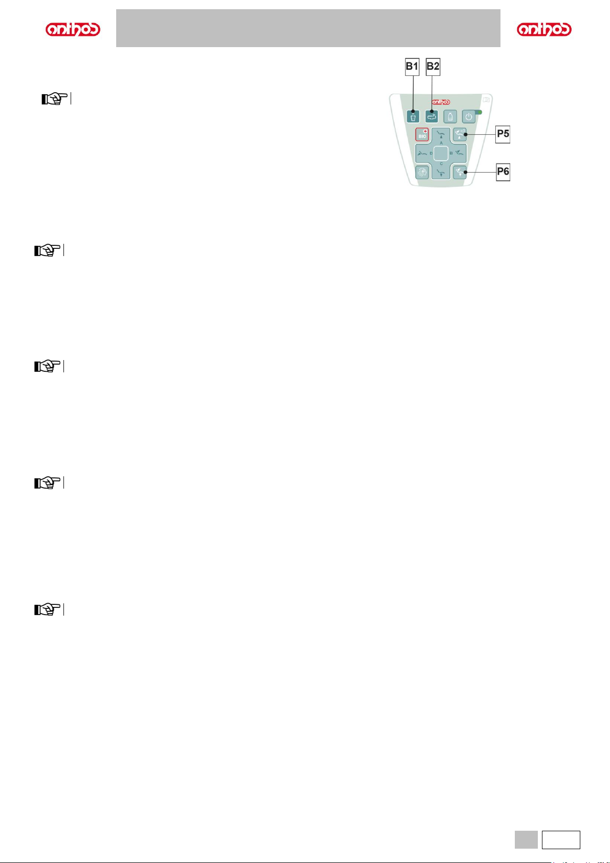
A5 - A6 PLUS - L6
EN
63
Adjusting the amount of water used to fill the cup.
• Turn on the dental unit holding down the button (B1) on the assistant’s
board.
1 intermittent BEEP signals saving is in progress.
• Press the button (B1) once to start filling the cup.
• Once the desired water level has been reached, press the button (B1)
again making sure the BEEP stops.
At this point, the new water level in the cup has been saved.
Changing bowl operation.
Water delivery to the bowl can take place in an untimed manner (ON/OFF
operation of the relative control button).
This modification is made by turning on the dental unit holding down button
(B2) on the assistant’s board.
A beep sounds to signal the selected operating mode.
• 1 BEEP: timed operation.
• 3 BEEPS: ON/OFF operation.
Timed operation is factory set.
Changing the water-to-bowl controller with water delivered to the
cup.
The controller that delivers water to the bowl when the button (B1) is
pressed can be turned on/off.
This modification is made by turning on the dental unit holding down
buttons (B1) and (B2) simultaneously on the assistant’s board.
A beep sounds to signal the selected operating mode.
• 1 BEEP: controller enabled.
• 3 BEEPS: controller disabled.
The controller is enabled by default.
Water-to-bowl controller modification upon recall of dental chair
RINSE POSITION.
The controller that delivers water to the bowl when the button (P5) is
pressed can be turned on/off.
This modification is made by turning on the dental unit holding down
buttons (P5) and (B2) simultaneously on the assistant’s board.
A beep sounds to signal the selected operating mode.
• 1 BEEP: controller enabled.
• 3 BEEPS: controller disabled.
The controller is enabled by default.
Water-to-bowl controller modification upon recall of dental chair
AUTOMATIC RETURN.
The controller that delivers water to the bowl when the button (P6) is
pressed can be turned on/off.
This modification is made by turning on the dental unit holding down the
dental chair’s buttons (P6) and (B2) simultaneously on the assistant’s
board.
A beep sounds to signal the selected operating mode.
• 1 BEEP: controller enabled.
• 3 BEEPS: controller disabled.
The controller is enabled by default.
Page 64
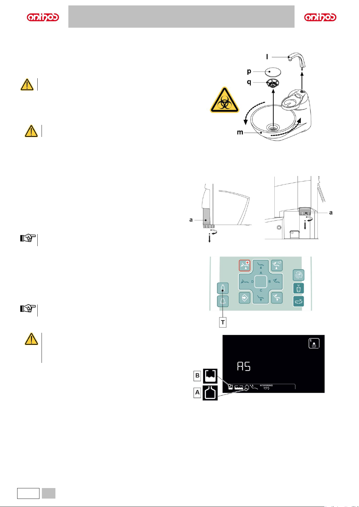
A5 - A6 PLUS - L6
64
EN
Spout, bowl and bowl filter removal.
• Pull up the spout (l) and take it off.
• Pull up the filter (q) and its cover (p) from the bowl to remove them.
• Release bowl (m) by turning it counter-clockwise, then pull it up to
remove it.
Disinfection and cleaning.
Always wear gloves to prevent contact with infected
material when cleaning the bowl and bowl filter.
The parts are to be cleaned daily at the end of each working day.
• Water dispensers: thoroughly wash with a specially formulated scaleremover (such as MD 550 Orotol DÜRR).
• Bowl filter: clean with running water and commercially-available
cleaning products.
Do not use acids or abrasive products.
7.2. S.H.S/S SYSTEM (SIMPLIFIED HYGIENIZATION SYSTEM)
Description of the system.
This system features a tank (a) suitable to contain the independent water
supply, preferably distilled water.
The tank has a total capacity of 1.8 litres and feeds:
• The sprays of all the instruments present on dentist's and assistant's
boards.
• The syringe present on the assistant's board.
• The cup filling system.
• The water quick coupling (if available).
The button (T) allows you to turn on/off the independent water supply.
Independent water supply active status is highlighted by icon (A)
appearing on the console DISPLAY.
This system also allows performing a disinfection cycle of instrument
spray ducts using disinfectant in the tank instead of the supply liquid.
Tank reserve warning.
When the fluid inside the tank drops below the reserve level, a special
warning icon (B) appears on dentist's board console.
Filling the tank.
Once tank min. level is reached (approx. 500 cc), fill it as follows:
S.H.S. system cannot be reactivated until liquid correct level in
the tank is restored.
• Remove tank (a) by turning it clockwise.
• Fill the tank until reaching the max. level.
Use distilled water or demineralised/deionised water. For
enhanced hygiene, it can be added with 600 parts per
million (ppm) of hydrogen peroxide by adding 35 ml of
Peroxy Ag+ or 35 ml of 3% Hydrogen Peroxide
(oxygenated water, 10 volumes).
Page 65
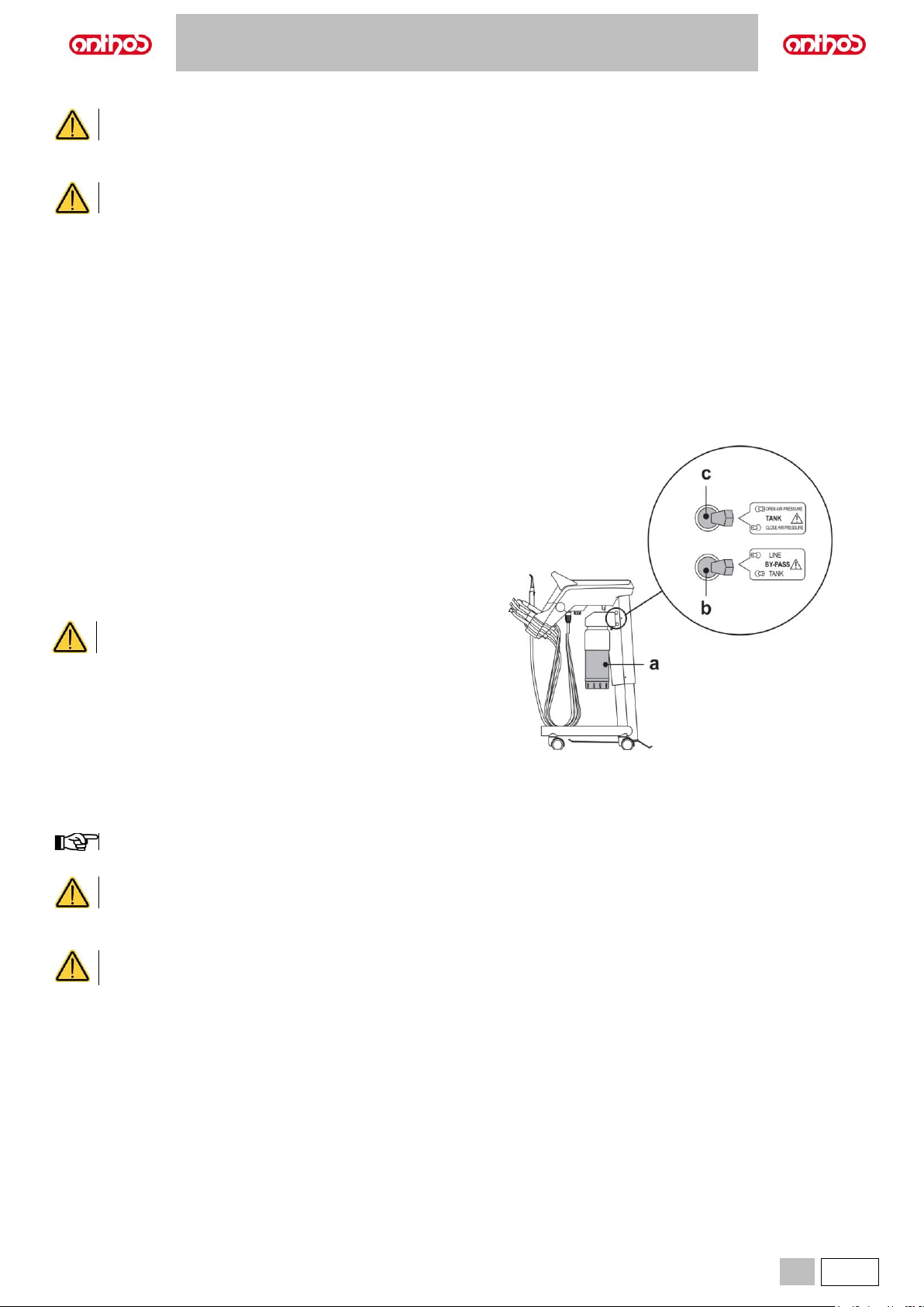
A5 - A6 PLUS - L6
EN
65
• Fit the tank back in place by turning it counter-clockwise.
Make sure that tank is duly fastened.
• Touch the button (T) to re-enable the S.H.S. system.
Check that icon (A) on DISPLAY turns on.
If you are going to be absent from the surgery for long periods of time (holidays), completely empty the tank (a) before leaving. It is
advisable to empty it by calling water to the cup (use the cup supplied), until air comes out of the nozzle.
Cleaning and disinfection of the tank.
It is recommended to periodically disinfect (at least once a month) the tank only, using as disinfectant Peroxy Ag+ Cefla or 3% Hydrogen Peroxide
(Oxygenated Water, 10 volumes), acting as follows:
• Remove tank from dental unit and drain it completely.
• Fill tank to the brim with the disinfectant.
• Allow the disinfectant to remain in the tank for at least 10 minutes.
• Drain disinfectant from the tank.
• Rinse tank with distilled water.
• Fill tank with distilled water, if necessary charging it with the substances indicated above.
• Fit tank back into its seat inside dental unit.
7.2.1. MANUAL S.H.S. SYSTEM (applied on A5 SINGLE CART model only)
System features a tank (a) for distilled water.
The tank has a total capacity of 1.8 litres.
Tank supplies:
• The sprays of all the instruments present on dentist's and assistant's
boards.
• The cup filling system.
• The water quick coupling (if available).
A by-pass toggle (b) allows disabling the system in case you want to
supply instruments with mains water.
This system allows performing a disinfection cycle of instrument spray
ducts using oxygenated water (see paragraph 7.2.2.).
Carry out a disinfection cycle at the end of every working
day.
Filling the tank.
Once tank min. level is reached (approx. 500 cc), fill it as follows:
• Switch the toggle (c) to "CLOSE AIR PRESSURE” position.
• Remove tank (a) by turning it clockwise.
During this operation the pressurised air present inside the tank will be automatically bled to the outside.
• Pour distilled water inside the tank until reaching the max. level.
Use distilled water only. For enhanced hygiene, it can be added with 600 parts per million (ppm) of hydrogen peroxide using 20 ml
of Peroxy Ag+ per litre of distilled water, or oxygenated water (20 ml of 3% oxygenated water per litre of distilled water).
• Fit the tank back in place by turning it counter-clockwise.
• Switch the toggle (c) back to "OPEN AIR PRESSURE" position.
• Make sure that the tank is correctly secured in place before switching toggle (c) to "OPEN AIR PRESSURE" position.
• If you are going to be absent from the surgery for long periods of time (holidays), completely empty the tank (a) before leaving.
Page 66
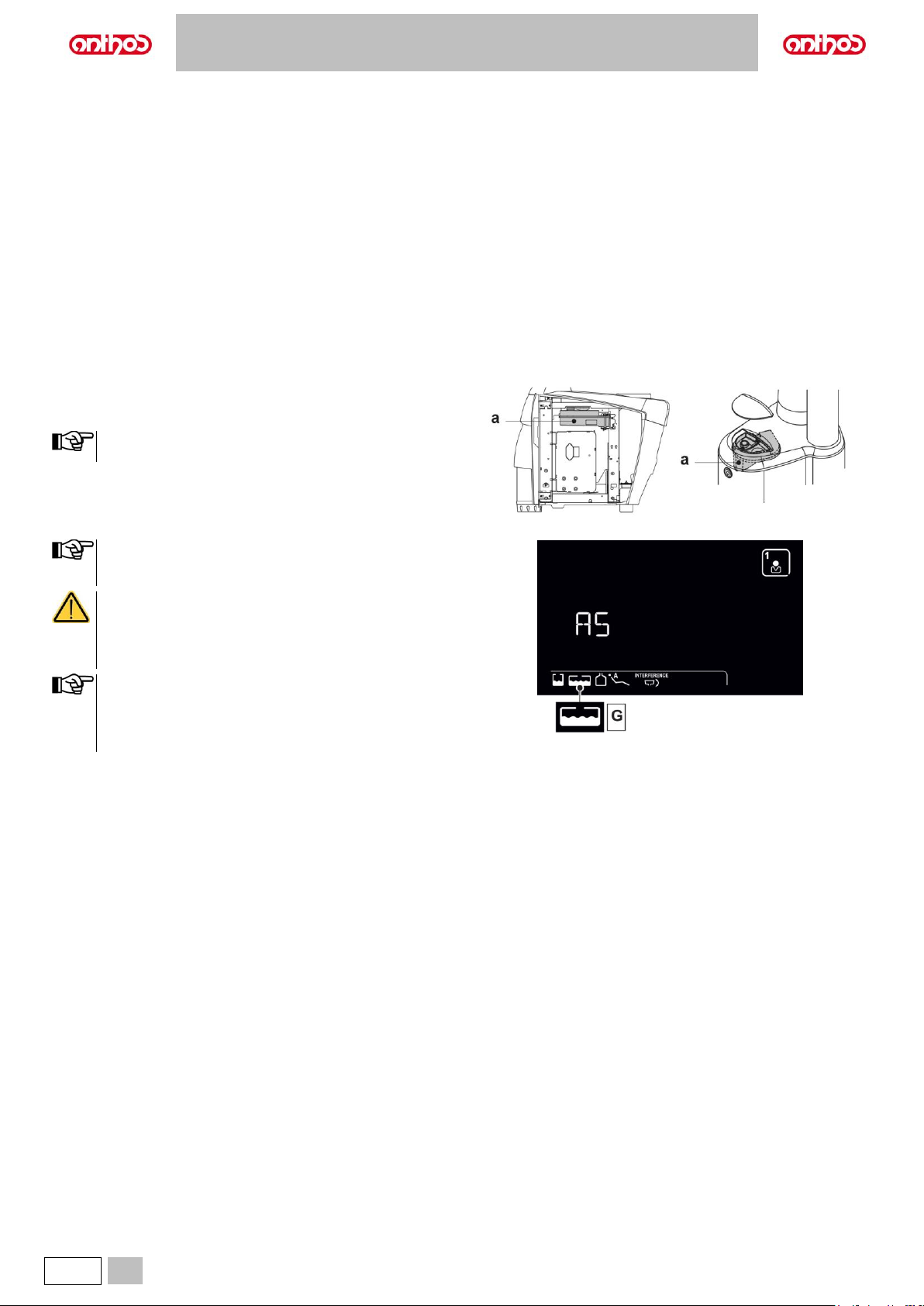
A5 - A6 PLUS - L6
66
EN
BY-PASS button.
The system can be disabled in case you want to supply instruments with mains water.
This function is carried out by switching toggle (b) to "LINE" position.
Switch toggle (b) back to "TANK" position to go back to distilled water operation.
Cleaning and disinfection of the tank.
See paragraph 7.2.
7.3. W.H.E. SYSTEM (WATER HYGIENIZATION EQUIPMENT)
The W.H.E. system ensures a safe, physical, separation of the dental unit water system from the water mains thanks to a water free fall section (in
compliance with EN 1717).
In addition, system continuously delivers hydrogen peroxide inside water circuit with a final concentration inside ducts of 0.06% (600 ppm), which is
suitable to carry out bacteriostasis.
To this end, the use of PEROXY Ag+ (CEFLA s.c.) is recommended; or 3% Hydrogen Peroxide (oxygenated water, 10 volumes).
Description of the system.
The W.H.E. system is positioned inside the connection box and is always
active.
A tank (a) located inside the water unit contains approx. 500 cc. of
disinfectant fluid to supply the system.
• The W.H.E. system is automatically disabled when the S.H.S.
system is enabled.
Disinfectant fluid running out warning.
When the oxygenated water present in the tank (a) is running out, the
dental unit emits an intermittent sound (3 BEEPS) that is repeated at every
start-up of the equipment.
• For console with LCD Touch DISPLAY:
A specific icon (G) on the dentist's console display signals that
the tank (a) contains a sufficient amount of disinfectant fluid.
If disinfectant fluid has run out, the dental unit will
nevertheless continue working, but it will use UNTREATED
mains water.
We recommend topping up disinfectant fluid as soon as
possible.
The exhaustion of the disinfectant inside the tank also causes a
clear slowdown in the operations of use of the W.H.E. system,
which should not be considered a fault. The normal operation of
the system is obtained by restoring the correct level of
disinfectant inside the relevant tank.
Page 67
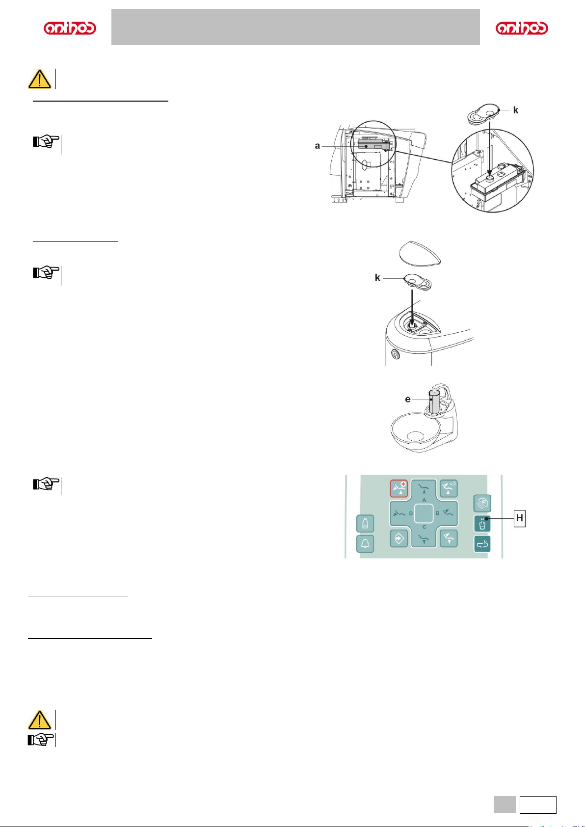
A5 - A6 PLUS - L6
EN
67
Disinfectant fluid tank filling
To fill up, use pure PEROXY Ag+ or 3% oxygenated water (10 volumes) only, without diluting them.
Dental units of A5 and A6 PLUS model
• Open the water unit side cover.
• Turn the tank (a).
• Remove plug (k) and pour disinfectant fluid inside tank until it is full.
The plug shape allows it to be used as a funnel to make filling
easier.
• Refit plug and tank.
• Lastly, close the water unit side cover.
Dental units of L6 model
• Open tank flap.
• Remove plug (k) and pour disinfectant fluid inside tank until it is full.
The plug shape allows it to be used as a funnel to make filling
easier.
• Refit plug and close tank flap.
Emptying the W.H.E. system water circuit
This function allows emptying the W.H.E. system water circuit in case the
dental unit must stay off for several days.
Proceed as follows:
• Place the supplied container (e) under cup spout and enable the water
circuit emptying cycle by keeping the button (H) pressed for at least 5
seconds; the display shows the system’s code.
• Wait for the water circuit to be emptied, a sound (3 BEEPS) will be
emitted at the end of the operation.
• Now the dental unit is in lockout mode and it can be turned off.
At restart, theW.H.E. system will be automatically restored.
Warning messages on Display.
Console with Digit DISPLAY:
If the system detects a fault operation, it emits an intermittent sound (2 BEEPS) and locks out, preventing water from being delivered to the dental unit.
In these cases, it is recommended to first check the correct supply of water and air to the dental unit.
Then turn the dental unit off and on again, if the lockout condition persists, call the Technical Service department.
Console with LCD Touch DISPLAY:
If system detects a malfunction, an error message will be displayed (see paragraph 10).
If the detected error is negligible, the dental unit continues working, while in case of severe errors, the dental unit will be blocked and Technical Service is
required.
PEROXY Ag+ storage.
For proper PEROXY Ag+ storage, follow the manufacturer’s instructions given on the package.
It is important to keep the package tightly closed and stored in a cool place at a temperature not exceeding 25°C.
Never leave PEROXY Ag+ or oxygenated water in the tank (a) for more than one month.
If you are going to be absent from the surgery for long periods of time (holidays), completely empty the tank (a) before leaving.
To empty tank, use a suction tube.
Page 68
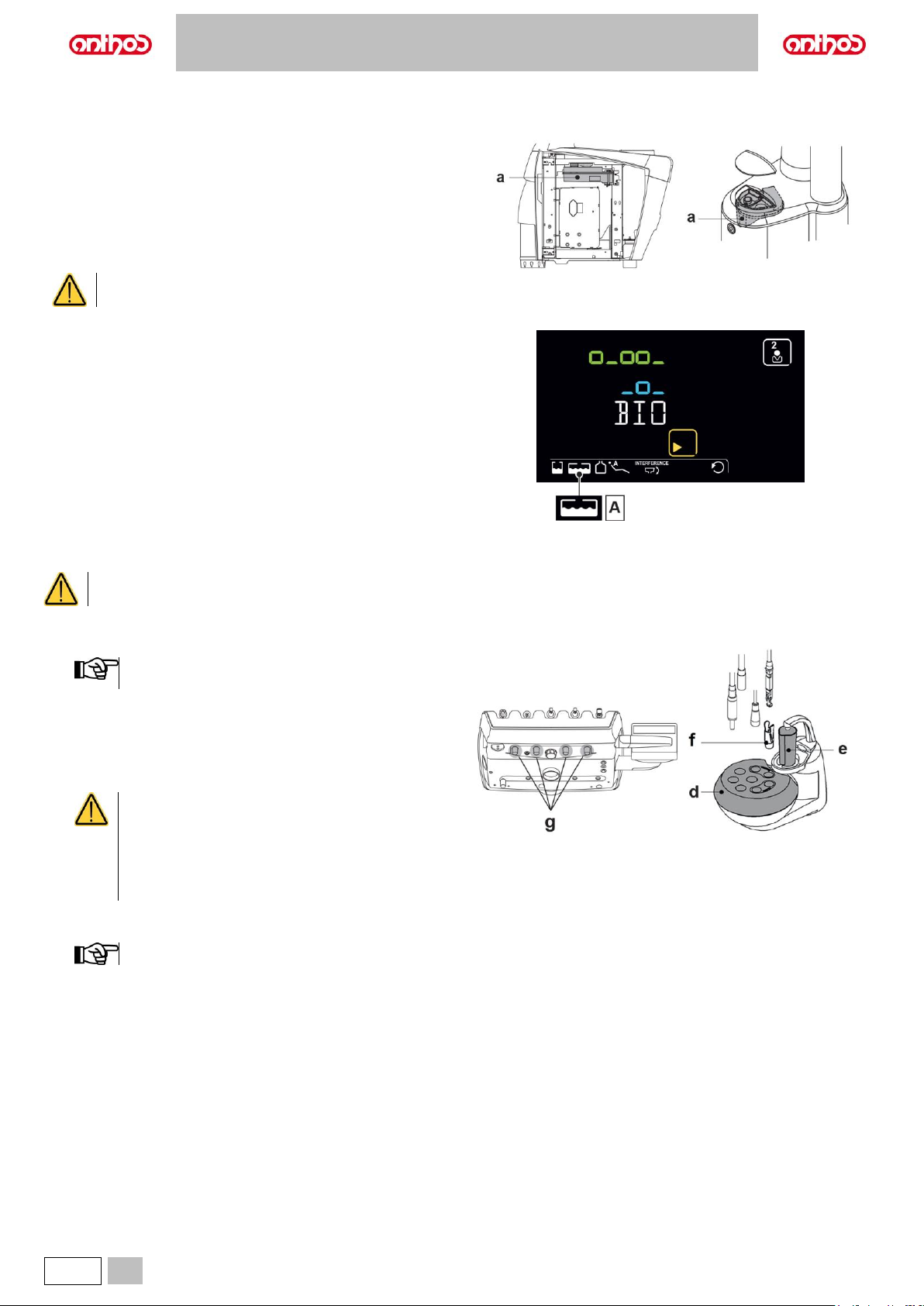
A5 - A6 PLUS - L6
68
EN
7.4. BIOSTER S AUTOMATIC DISINFECTION SYSTEM (only dental units with LCD Touch DISPLAY)
Description of the system.
This system allows carrying out an automatic disinfection cycle of the
water circuits of the following instruments:
• All instruments that require water for their use are placed on the dentist's
board.
• The syringe and any other instruments that require water for their use
are placed on the assistant's board.
• Water-to-cup ducts.
In addition, system features a tank (a) positioned inside the water unit and
suitable to contain approx. 500 cc. of disinfectant fluid.
Carry out a disinfection cycle at the end of every working
day.
Disinfectant fluid running out warning.
When the disinfectant fluid present inside tank (a) is running out, a special
warning icon (A) appears on the DISPLAY, an error message appears on
the DISPLAY and 3 warning BEEPS are emitted and repeated whenever
dental unit is turned on.
Disinfectant fluid tank filling.
See paragraph 7.3.
To fill up, use pure PEROXY Ag+ or 3% oxygenated water
(10 volumes) only, without diluting them.
Setting the disinfection cycle.
• Check disinfectant fluid level inside tank and, if necessary, top up.
The disinfection cycle will not be activated if the fluid level
inside tank is below reserve level.
• Use the button "BIO" on the assistant's board to access the "BIOSTER
S disinfection cycle setting" menu and set the residence time of the
disinfectant fluid inside instrument water ducts (see paragraph 5.1.1.1).
• Position the special container (d) for the instruments to be disinfected
on the bowl.
• Insert the hoses of the instruments to be disinfected in the container
For the syringe instrument, it is necessary to remove the
handle and completely insert the dedicated adapter (f)
(second click). The heating system must be switched off.
The micromotor hose must be fully inserted inside motor
body.
Turbine and scaler hoses must be inserted without the
handpiece.
• Should you wish to disinfect suction tubes, insert tube terminals inside
the special couplings under manifold (see paragraph 7.5.).
Make sure that suction tube terminals are open.
• If water-to-cup duct disinfection is selected, place the special supplied
cup (e) under cup spout.
• Make sure that spray cocks (g), positioned on board lower side, are fully
open.
Page 69
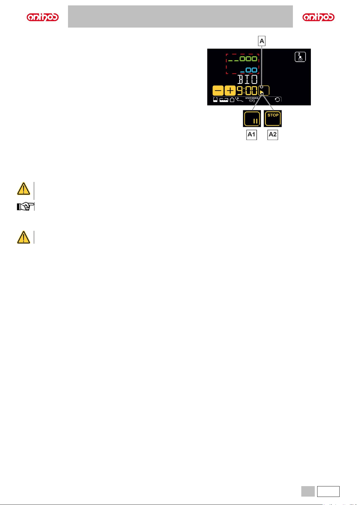
A5 - A6 PLUS - L6
EN
69
Performing the disinfection cycle.
• Start the automatic disinfection cycle by touching “PLAY” icon button (A)
on the LCD Touch DISPLAY or by pressing the “BIO” button on the
assistant's board.
• Now the system automatically performs the following operations:
- Emptying water ducts of instruments with air.
- Introduction of disinfectant fluid and starting of the counting of the
previously-set residence time.
- Once time has elapsed, start of a new duct emptying phase with
air.
- Ducts flushing with mains water or with independent supply fluid
(only if BIOSTER S system is installed and active).
Disinfection cycle interruption.
• Touch “PAUSE” icon button (A1) to interrupt the disinfection cycle at any
time.
• Touch the "STOP” icon button (A2) within 5 seconds to stop the
disinfection cycle in progress and cancel it definitively.
After 5 seconds, touch “PAUSE” icon button (A1) to resume disinfection
cycle from where it was interrupted.
PEROXY Ag+ storage.
For proper PEROXY Ag+ storage, follow the manufacturer’s instructions given on the package.
It is important to keep the package tightly closed and stored in a cool place at a temperature not exceeding 25°C.
Never leave PEROXY Ag+ or oxygenated water in the tank (a) for more than one month.
After your absence from the surgery for long periods of time (holidays), completely empty the tank (a) before restarting the dental
unit.
To empty tank, use a suction tube.
Warning messages on DISPLAY.
If system detects a malfunction, a warning message will be displayed (see paragraph 10).
In case of irregular interruption of the disinfection cycle, the equipment will stay in lockout condition until the disinfection cycle is
run again or a flushing cycle is carried out.
Page 70
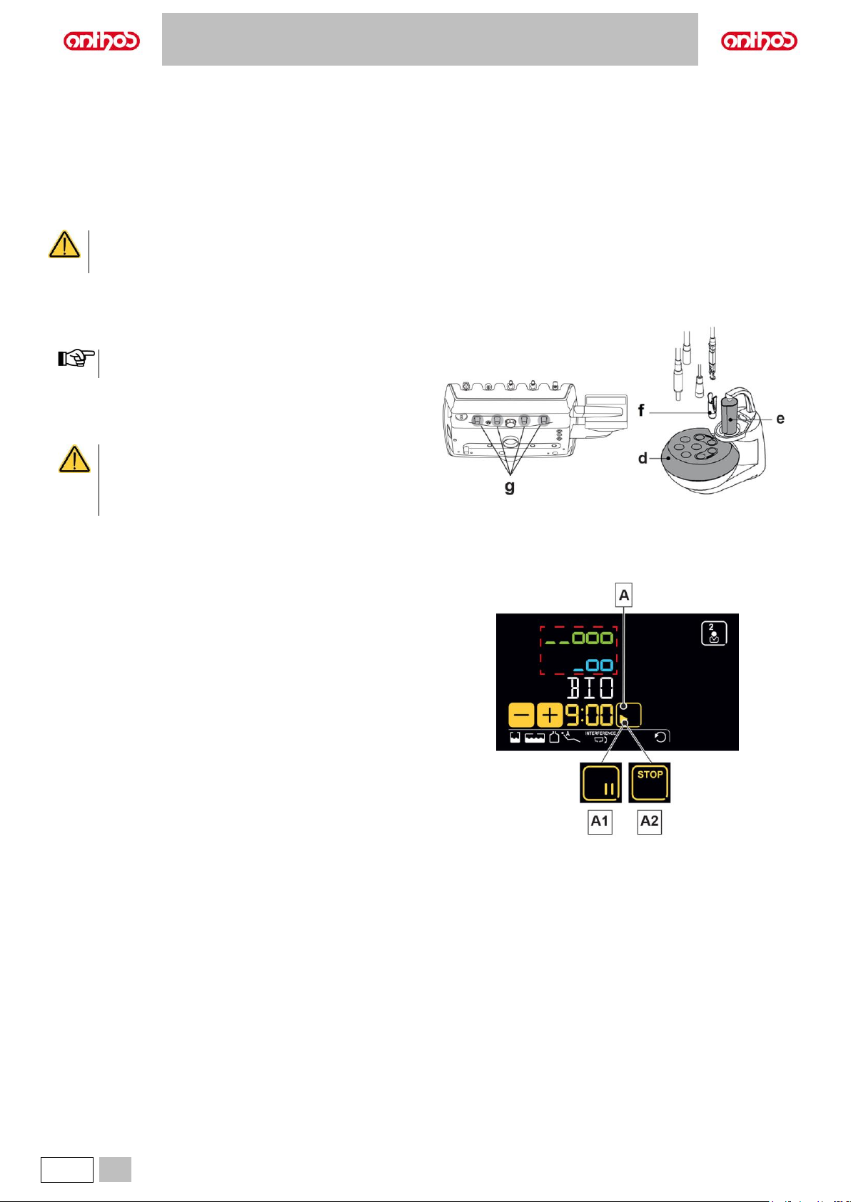
A5 - A6 PLUS - L6
70
EN
7.5. AUTOMATIC INSTRUMENT FLUSHING CYCLE
Description of the system.
This system allows carrying out an automatic FLUSHING cycle to renew
water present in the water ducts of the instruments on the dentist’s and
the assistant’s boards and the water-to-cup duct.
The flushing cycle can be carried out with mains water, with W.H.E.
system (if installed) or with S.H.S. system (if installed).
Available cycles are two:
- QUICK FLUSHING (cycle time: 20 seconds).
- LONG FLUSHING (cycle time can be set from 2 to 10 minutes).
It is advisable to carry out a LONG FLUSHING cycle at the
beginning of each working day and a QUICK FLUSHING
cycle between two patients.
Flushing cycle setting.
• If the S.H.S. system is installed and you wish to carry out the flushing
cycle with distilled water, make sure that the relevant icon on the console
DISPLAY is on (see paragraph 7.2.).
It is advisable to execute the flushing cycle with tank
completely full.
• Use the DISPLAY to access the "FLUSHING cycle setting" menu, and
set cycle time (see paragraph 5.1.1.1).
• Position the special container (d) for the instruments to be treated on
the bowl.
For the syringe instrument, it is necessary to remove the
handle and completely insert the dedicated adapter (f)
(second click). The heating system must be switched off.
Turbine and scaler hoses must be inserted without the
handpiece.
• Insert the special supplied container (e) under the cup spout.
• Make sure that spray cocks (g), positioned on board lower side, are fully
open.
Performing the flushing cycle.
• Touch "PLAY” icon button (A) on the LCD Touch DISPLAY to start the
flushing cycle (see paragraph 5.1.1.1.).
• At the end of the flushing cycle, put the instruments extracted back into
place to return to the working condition.
Flushing cycle interruption.
• Touch “PAUSE” icon button (A1) to interrupt the flushing cycle at any
time.
• Touch the "STOP” icon button (A2) within 5 seconds to stop the flushing
cycle in progress and cancel it definitively.
• After 5 seconds, touch “PAUSE” icon button (A1) to resume flushing
cycle from where it was interrupted.
Warning messages on DISPLAY.
If system detects a malfunction, a warning message will be displayed (see
paragraph 10).
Page 71
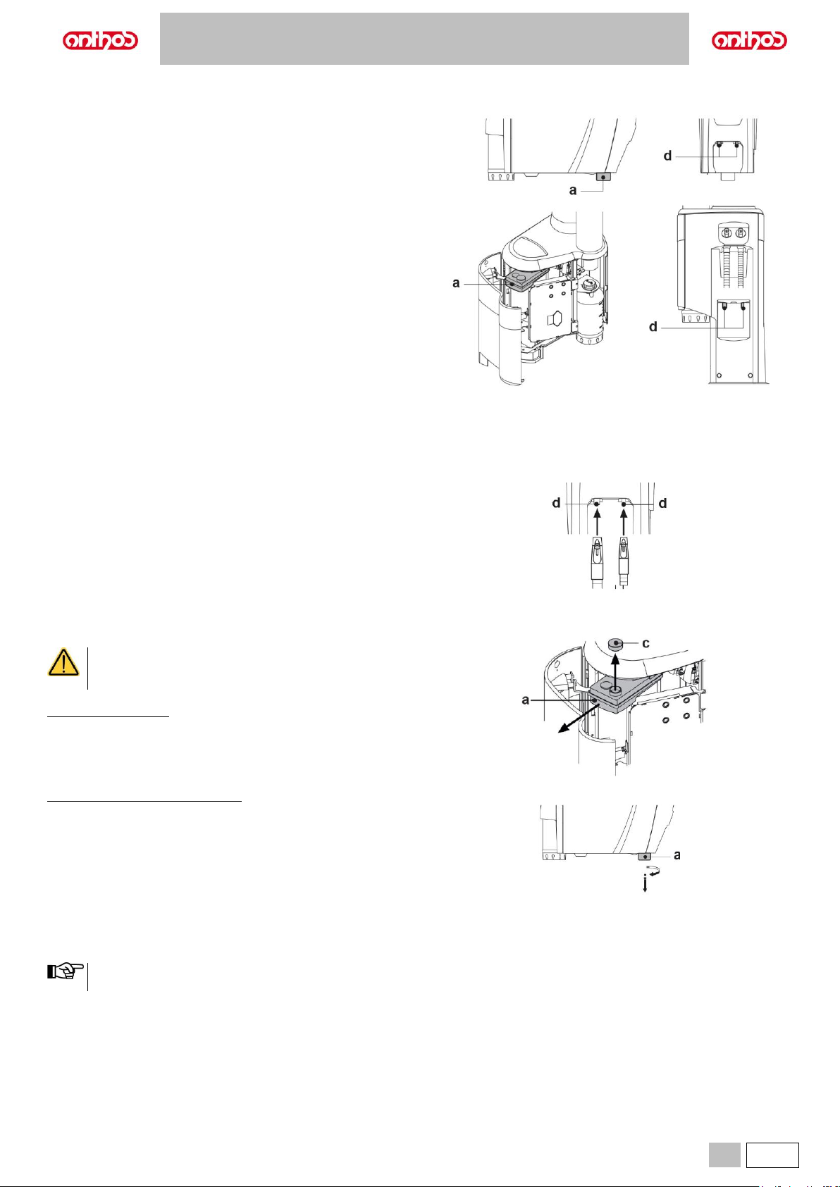
A5 - A6 PLUS - L6
EN
71
7.6. A.C.V.S. SYSTEM (AUTOMATIC CLEANING VACUUM SYSTEM)
Description of the system.
This system allows cleaning the suction lines.
System features a tank (a) with detergent fluid and two couplings (d) used
for suction tube flushing.
Detergent fluid tank has a total capacity of approx. 550 cc (L6) or 250 cc
(A5 and A6 PLUS).
The flushing cycle is automatic and should usually be carried out at the
end of each surgery so as to complete the dental unit cleaning and
disinfection procedure.
How to start the flushing cycle.
To start the flushing cycle, proceed as specified below:
• Make sure that tank (a) contains enough detergent fluid.
• Remove both suction tube terminals from assistant's board supports,
making sure that suction motor starts.
• Open the mechanical covers of the suction tube terminals (opening lever
completely up).
• Insert suction tube terminals inside the relevant couplings (d) located
under manifold.
The vacuum created inside the Venturi tubes starts the flushing cycle.
• Now simply put suction tube terminals back into their supports on
assistant's board to go back to working condition.
Filling the tank.
It is recommended to use STER 3 PLUS (CEFLA s.c.) diluted
in a 6% solution (equivalent to 60 ml of product in 1 litre of
water).
Dental units of L6 model
• Open the water side unit cover (see paragraph 7.7.).
• Remove tank (a), taking care not to lift it up.
• Remove plug (c) and pour disinfectant fluid inside tank until it is full.
• Refit plug and tank.
• Lastly, close the water unit side cover.
Dental units of A5 and A6 PLUS model
• Move the dental chair fully up.
• Remove tank (a) by rotating it counter-clockwise.
• Pour the detergent liquid into the tank until it is full.
• Refit the tank (a) by turning it clockwise.
Stopping the flushing cycle.
If system detects a malfunction, a warning message will be displayed (see
paragraph 10).
Once stop causes are removed, the flushing cycle will restart
automatically.
Page 72
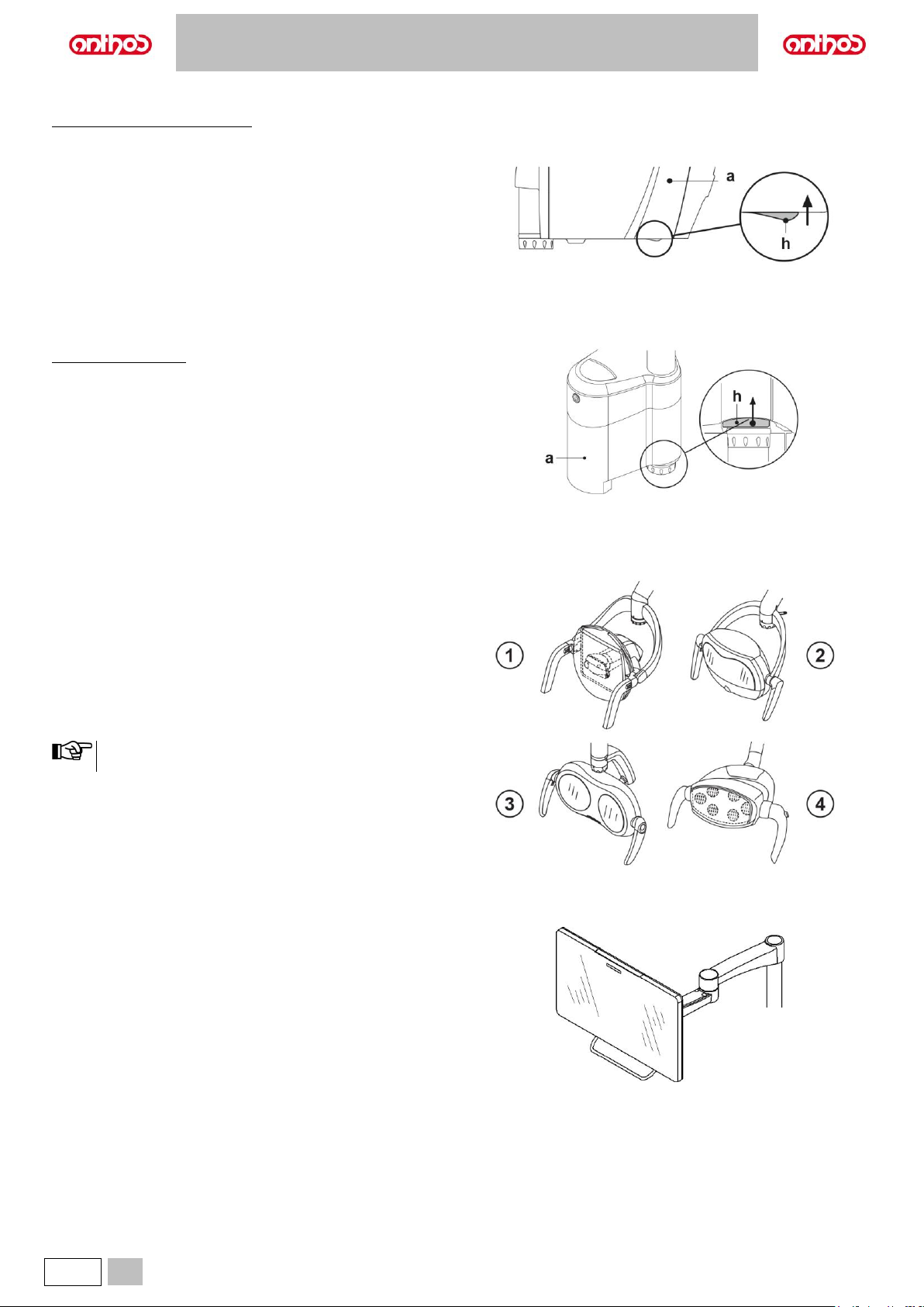
A5 - A6 PLUS - L6
72
EN
7.7. OPENING/CLOSING THE WATER UNIT SIDE COVER
Dental units model A5 and A6 PLUS
Opening the cover.
• disengage water unit side cover (a) by grasping handle (h) and pulling
it up.
Closing the cover.
• close the cover until you feel the mechanical locking of the handle (h).
Dental units of L6 model
Opening the cover.
• turn water unit side cover (a) after having released the special locking
handle (h).
Closing the cover.
• close water unit side cover, making sure it locks with handle (h).
8. ACCESSORIES
8.1. OPERATING LAMP
The operating light comes in 4 models:
1 Lamp with halogen light source, VENUS PLUS model.
2 Lamp with LED light source, VENUS PLUS-L model.
3 Lamp with LED light source, VENUS PLUS-L model MCT version.
4 Lamp with LED light source, VENUS e model.
The instructions for use and maintenance of the lamps are available in
PDF format and can be downloaded from the download area of the
www.anthos.com.
During the automatic movements of the dental chair, the lamp
automatically turns off to prevent blinding the patient.
8.2. MONITOR ON LAMP POLE
The instructions for use and maintenance of the monitor are provided with
the device.
Page 73
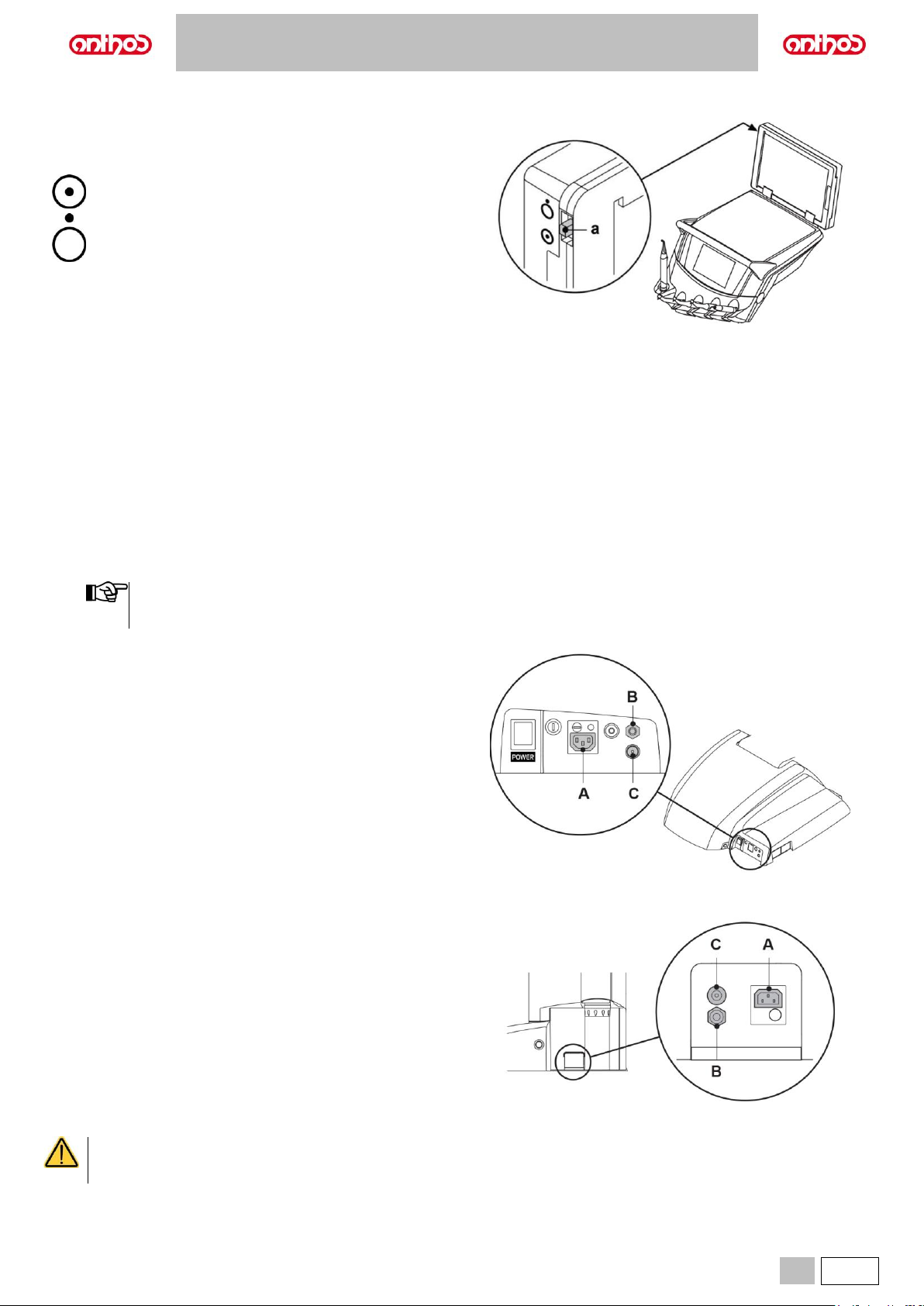
A5 - A6 PLUS - L6
EN
73
8.3. NEGATOSCOPE FOR PANORAMIC X-RAYS
A negatoscope for panoramic x-rays can be mounted on all
INTERNATIONAL version dentist's boards.
The screen dimensions are as follows: H = 210mm, L = 300mm.
To turn on negatoscope, simply turn special switch (a):
Negatoscope on.
Negatoscope off.
8.4. AIR/WATER/230V QUICK-COUPLINGS
A Power outlet: 230Vac 2A in accordance with IEC/EN 60320-2-2/F
(only on dental units with 220-240Vac power supply).
B Air quick coupling: pressure 6 Bar.
C Water quick coupling: pressure
- with mains water, 2.5 Bar;
- with S.H.S. system, 1.8 Bar;
- with W.H.E. system, 3 Bar.
- with mains water, 1800 ml/min;
- with S.H.S. system, 950 ml/min;
- with W.H.E. system, 400 ml/min.
With the S.H.S. independent water supply system, in order
to use the quick-coupling with mains water, the relevant
tank needs to be disabled (see paragraph 7.2.).
Dental units of A5 and A6 PLUS model
Dental units of L6 model
• Switch off the equipment before attempting to connect or disconnect the air/water outlets.
• After each use and before disconnecting the water inlet, operate the connected instrument for 20 seconds with no load to perform
a manual flushing of the duct.
Page 74
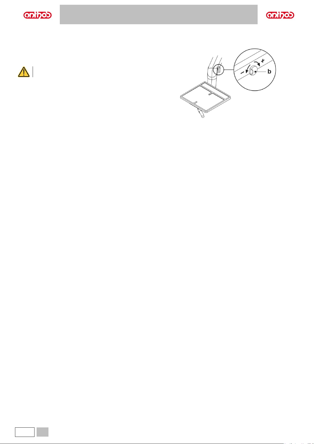
A5 - A6 PLUS - L6
74
EN
8.5. AUXILIARY TRAY HOLDER
Applied only on models L6 SIDE DELIVERY and A5 CART.
Tray holder can contain two standard size trays.
Turn knob (b) to adjust vertical movement based on load:
• Turn clockwise to increase resistance (heavy loads).
• Turn counter-clockwise to decrease resistance (lightweight loads).
Maximum permitted load on the tray: 3.5 Kg (without
negatoscope) or 2.5 Kg (with negatoscope).
Page 75
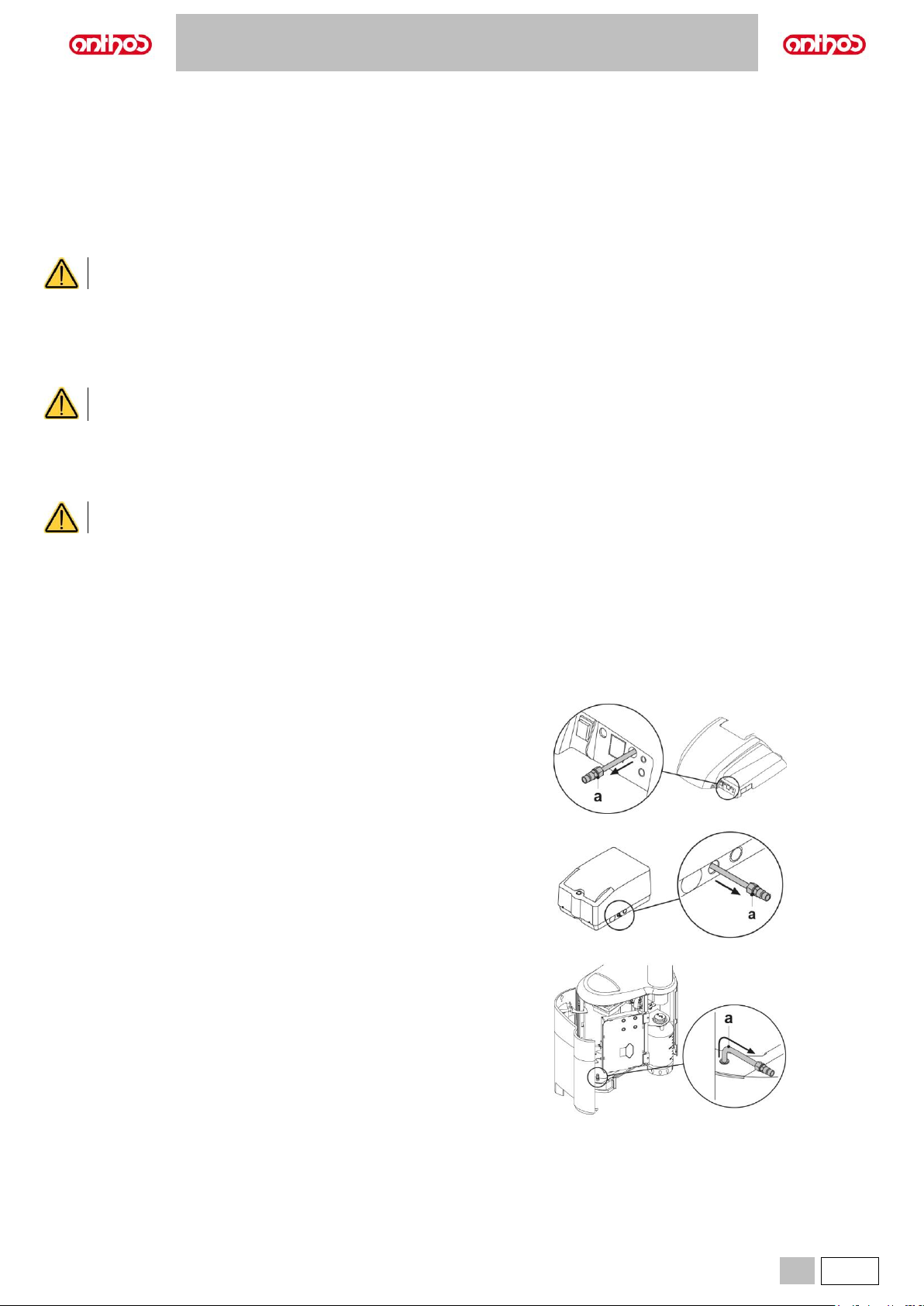
A5 - A6 PLUS - L6
EN
75
9. MAINTENANCE
Preventive maintenance
CEFLA s.c., the manufacturer of the medical devices, in accordance with applicable standards IEC 60601-1 3rd Ed. - 2007, IEC 62353 and Directive MDD
93/42, as amended and supplemented, for medical devices underlines that the following scheduled maintenance checks specified in the Technical Service
Manual are to be carried out by authorised personnel at least once every 12 months:
• Checking the supplies (air, water, electricity).
• Checking the anti-crushing safety devices, movement of arms and dental chair.
• Checking and adjusting the device (water supply, suction, foot control) and instruments.
• Checking the operating light, the multimedia system, the hygiene systems.
• Measurement of protective conductor resistance and leakage currents.
The warranty is void if the equipment is serviced, repaired, altered or modified in any way by personnel who have not been duly
authorised by CEFLA s.c..
Safety checks.
In accordance with standard IEC 62353, the safety checks specified in the Technical care manual and Maintenance and warranty handbook supplied with
the dental unit are to be carried out at the intervals required by current local regulations. If no precise indications are given, CEFLA s.c.,, the manufacturer
of the dental units, recommends checking them at least every 24 months at the time of installation and whenever electrical parts that are live are
repaired/updated.
The manufacturer shall not be held liable for any personal injury or equipment damage if the precautions given above are not observed.
9.1. MAINTAINING THE INSTRUMENTS
Maintenance instructions for the instruments are enclosed with each instrument.
Maintenance of the instruments should be carried out with the equipment switched off.
9.2. DRAINING CONDENSATE
Perform this operation every day before starting work.
Proceed as follows:
• Remove the condensate drain cock (a).
• Place a container under condensate drain cock (a).
• Loosen the cock knob.
• After the draining is complete, fully close the cock.
Dental units of A5 and A6 PLUS model.
Dental units of A5 SINGLE CART model.
Dental units of L6 model.
Page 76
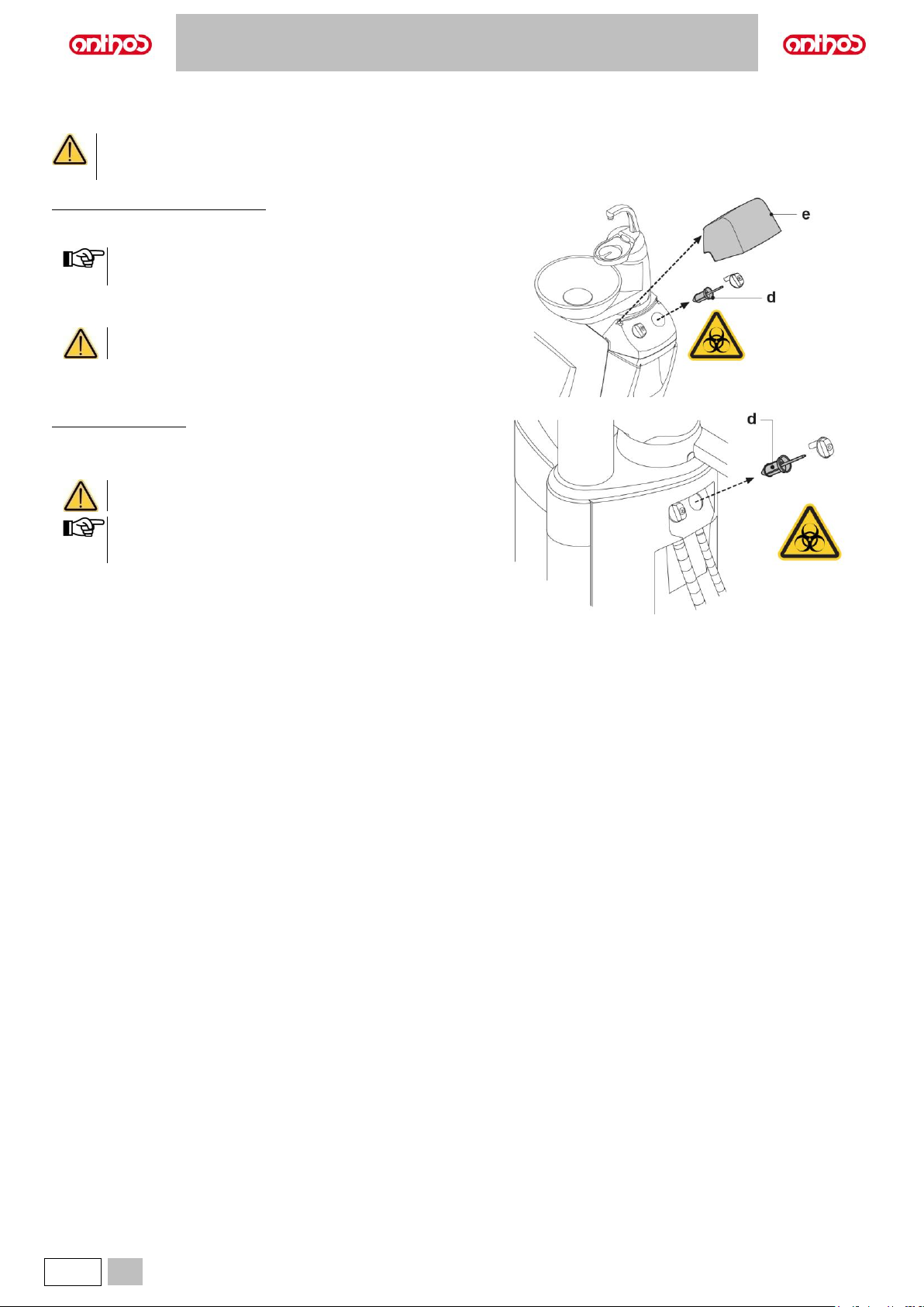
A5 - A6 PLUS - L6
76
EN
9.3. SUCTION FILTER CLEANING
This operation should be done daily at the end of work.
BIOLOGICAL HAZARD
Always wear goggles and gloves to prevent contact with
infected material when cleaning the suction filters.
Dental units of A5 and A6 PLUS model
• Remove filter door (e) from its seat by pulling it up.
• One at a time, remove filters (d).
The filter door can be used as a container for the transfer to
the cleaning area.
• Clean/replace the filters (code 97461845).
• Refit filters.
Before refitting the filter, make sure to remove any
amalgam residues still present on each filter seat mouth.
Dental units of L6 model
• One at a time, remove filters (d).
• Clean/replace the filters (code 97461845).
• Refit filters.
Before refitting the filter, make sure to remove any
amalgam residues still present on filter seat mouth.
In order to prevent any dripping of liquids and secretions from
the filter being removed, it is advisable to carry out the above
operations with the suction tube working.
Page 77
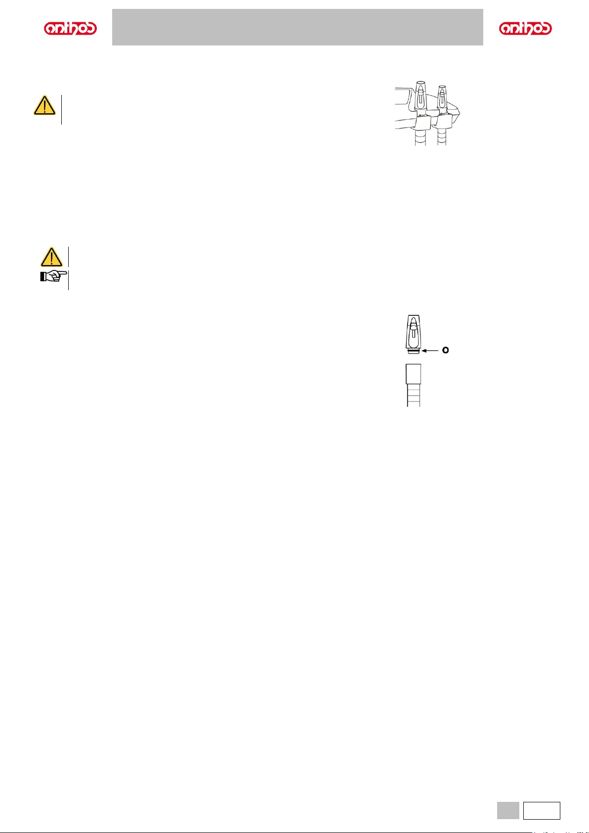
A5 - A6 PLUS - L6
EN
77
9.4. SUCTION LINES
The suction lines must be disinfected using a product suitable for this
purpose.
For cleaning of the suction system, it is recommended to
use STER 3 PLUS (CEFLA s.c.) diluted in a 6% solution
(equivalent to 60 ml of product in 1 litre of water).
At the end of each surgical procedure.
• Perform an automatic flushing cycle or suck in about 1/2 litre of
sanitising solution with each one of the suction tubes used.
• Sterilize the suction tube holder terminals in a steam autoclave
(see paragraph 1.6).
At the end of each working day.
• Suck in 1 litre of water with each suction tube, alternating water and air
(keep the suction tube alternately in and out of the water).
• After rinsing with water, suck in about 1/2 litre of sanitising solution with
each one of the suction tubes used.
All sanitising products must be used as specified by the
manufacturer.
After flushing and disinfection, it is good practice to suck in air
only to dry the entire suction system (5 minutes).
Once a week.
Remove the suction tube body from its hose attachment and lubricate the
O-ring (o) using S1-Protective Lubricant for O-Rings (CEFLA s.c.).
Once a year.
Replace the suction tubes and suction tube holder terminals.
Page 78
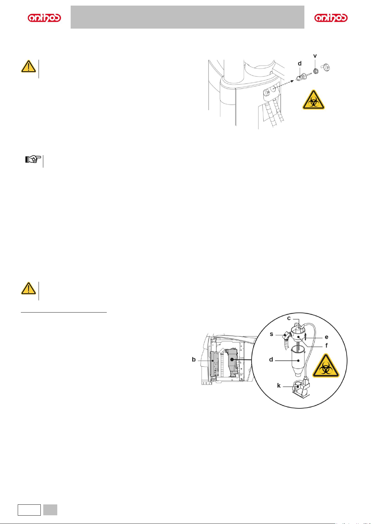
A5 - A6 PLUS - L6
78
EN
9.5. AIR-LIQUID SEPARATOR CANISTER BY CATTANI
At the beginning of each working day.
Insert inside filter (d) a defoaming tablet (v).
BIOLOGICAL HAZARD
Always wear gloves and goggles to prevent contact with
infected material when carrying out this operation.
At the end of each surgical procedure.
• Perform an automatic flushing cycle or suck in about 1/2 litre of
sanitising solution with each one of the suction tubes used.
• Sterilize the suction tube holder terminals in a steam autoclave up to
135°C following the instructions for use of the device.
At the end of each working day.
• Suck in 1 litre of water with each suction tube, alternating water and air
(keep the suction tube alternately in and out of the water).
• After rinsing with water, suck in about 1/2 litre of sanitising solution with
each one of the suction tubes used.
After flushing and disinfection, it is good practice to suck in air
only to dry the entire suction system (5 minutes).
Every 15 days.
• Clean the separator container and probes with a soft non-abrasive
sponge and neutral detergent.
• Clean the drain valve for the separator’s container with the brush
provided for this purpose.
Once a year.
• By technician: check the siphons and drains, check all the internal tubes
and plastic and rubber parts subject to wear.
Before leaving the surgery for a few days.
• Start suction and run it for 20-30 minutes without sucking in any liquids.
The suction unit will dry completely. As a result, salt caused by moisture
and basic substances will not form. Said salt may cause fan seizure and
motor blockage.
How to remove the separator’s container.
BIOLOGICAL HAZARD
Always wear gloves to prevent contact with infected
material when carrying out the following operation.
Dental units of A5 and A6 PLUS model
• Move the dental chair fully up.
• Open the water unit side cover.
• Turn the electric box (b) after releasing the corresponding retainer.
• Completely empty the separator container, pressing the proper timed
button (c) located on the cover.
• If present, remove the valve (s) for centralised systems.
• Turn and raise the container until it is detached from the drain pump (k).
• Detach the container (d) from the cover (f) pulling up the two side rubber
bands (e).
• After the cleaning operations, refit the container (d) after lubricating the
O-rings with S1-Protective Lubricant for O-Rings (CEFLA s.c.).
Page 79
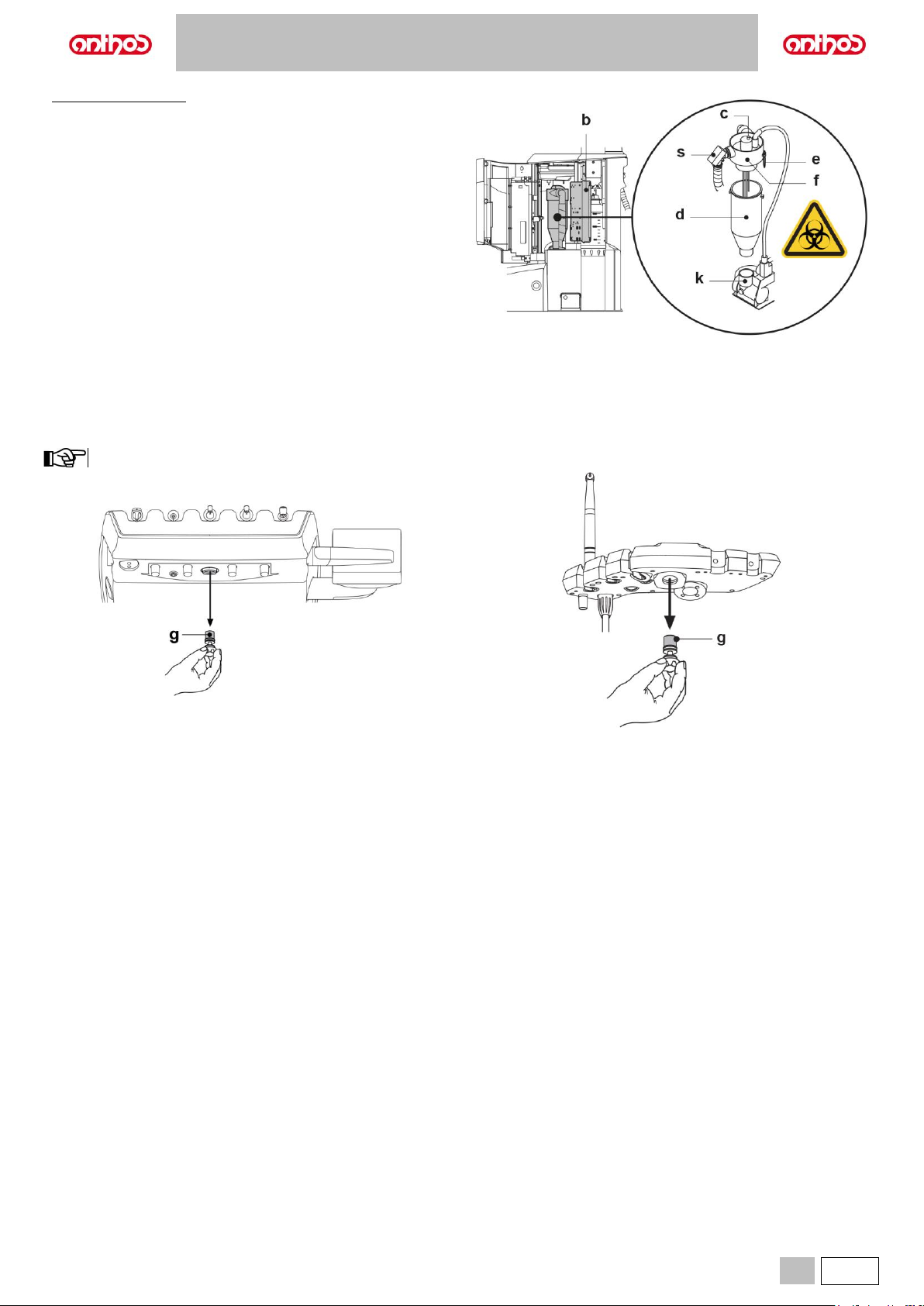
A5 - A6 PLUS - L6
EN
79
Dental units of L6 model
• Open the water unit side cover and turn the electric box (b) after
releasing the corresponding retainer.
• Completely empty the separator container, pressing the proper timed
button (c) located on the cover.
• If present, remove the valve (s) for centralised systems.
• Turn and raise the container (d) until it is detached from the drain pump
(k).
• Detach the container (d) from the cover (f) pulling up the two side rubber
bands (e).
• After the cleaning operations, refit the container (d) after lubricating the
O-rings with S1-Protective Lubricant for O-Rings (CEFLA s.c.).
9.6. CLEANING THE TURBINE RETURN AIR FILTER
Monthly check the oil container filter (g) present in the turbine’s return air line.
If necessary, replace the filter element (code 97290014).
If the micromotor instrument is also present on the assistant's board, remember that the relevant filters must be cleaned.
Page 80
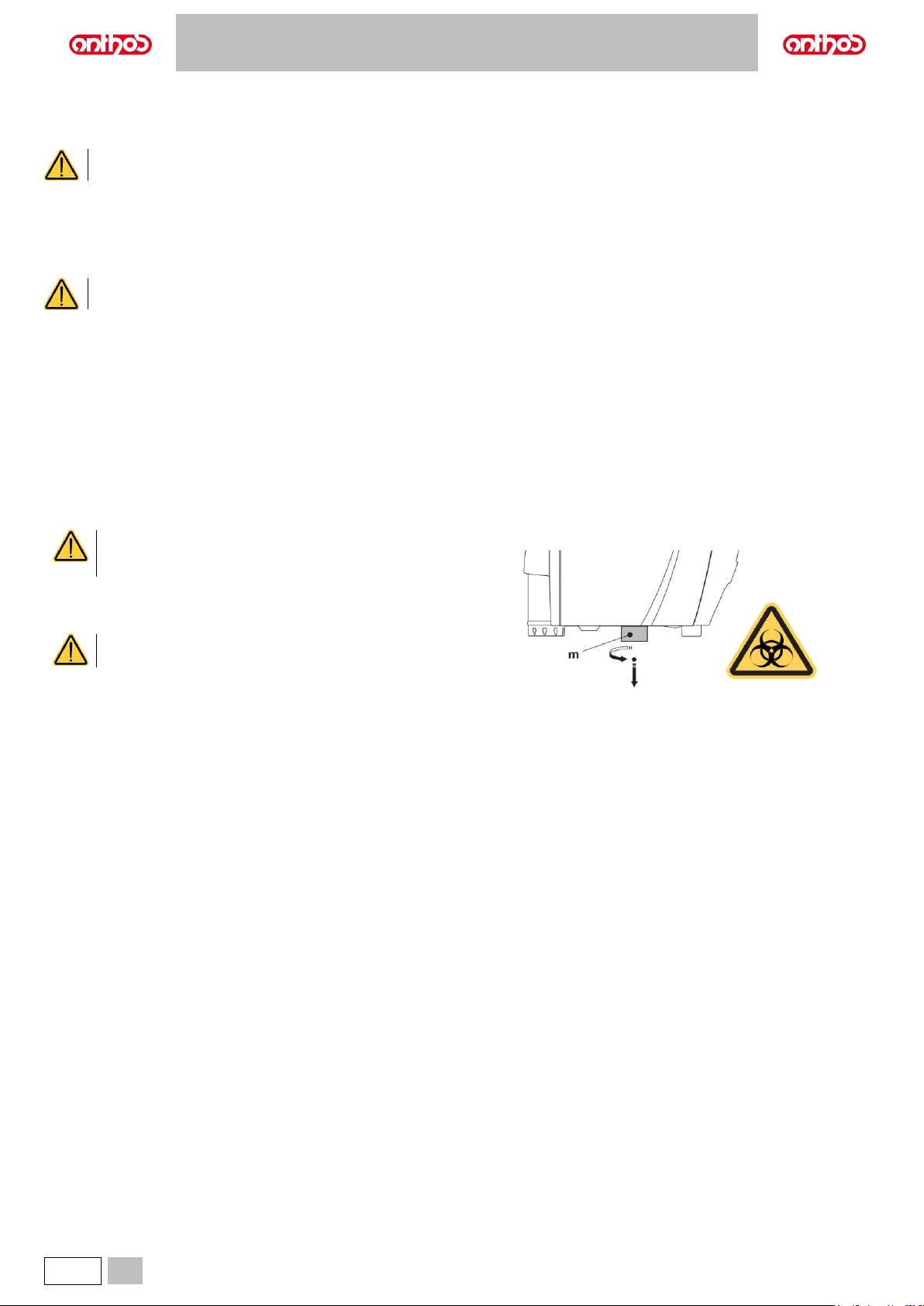
A5 - A6 PLUS - L6
80
EN
9.7. METASYS AMALGAM SEPARATOR
The maintenance instructions for the METASYS amalgam separator are enclosed with the equipment, if the equipment comes with this type of separator.
The separator control device is located in the water unit.
• Always wear goggles and gloves to prevent contact with infected material when cleaning the separator.
• When disposing of disposable containers full of amalgam, observe current local and national laws.
9.8. DÜRR AMALGAM SEPARATOR
The maintenance instructions for the DÜRR amalgam separator are enclosed with the equipment if the equipment comes with this type of separator.
The separator control device is located in the water unit.
• Always wear goggles and gloves to prevent contact with infected material when cleaning the separator.
• When disposing of disposable containers full of amalgam, observe current local and national laws.
9.9. DENTAL CHAIR
The dental chair does not need any special maintenance.
In any case, operation should be checked by the manufacturer's authorised personnel once a year.
9.10. CATTANI GRAVITY AMALAGAM SEPARATOR (dental units of A5 and A6 PLUS model only)
Draining the separator’s container.
• Move the dental chair completely up so that as much liquid as possible
can be drained from the container.
• Turn the container (m) counter-clockwise and remove it.
BIOLOGICAL HAZARD
Always wear gloves to prevent contact with infected
material when carrying out this operation.
• Refer to the instructions provided by CATTANI enclosed with the
equipment to drain the container in the disposable container provided
for this purpose (code 97290027).
When disposing of disposable containers full of amalgam,
observe current local and national laws.
Page 81
A5 - A6 PLUS - L6
EN
81
10. WARNING/ERROR MESSAGES
Two types of notices can be displayed on the console display: warning messages (Wxxx) and error messages (Exxx).
Warning messages (Wxxx) indicate situations that require user intervention.
Error messages (Exxx) indicate situations that cannot be fixed by the user and require the intervention of the Technical Service.
When contacting the Technical Service, please communicate the error number displayed.
Warning
Cause
Solution
W050
The disinfection cycle preparation page opens with the
instruments not in rest position.
To start a disinfection cycle, all disinfection instruments must be
in a rest position.
W051
BIOSTER S start request performed without selecting any
instrument or cup.
Select the instrument, cup or suction tubes, then activate the
disinfection cycle.
W057
The system has stopped the disinfection cycle after detecting
instruments changed during the cycle.
To restart the disinfection cycle after a lockout, use the same
instruments extracted during the stopped cycle.
W059
BIOSTER S start request performed without any extracted
instrument or selected cup.
Select the instrument or cup, then start the disinfection cycle.
W060
H2O2 tank empty.
Fill H2O2 tank.
W061
A user has requested to skip the disinfection pause.
None
W062
At the end of the cycle, a warning is issued if the pause has not
been made.
None
W063
H2O tank empty.
Fill H2O tank.
W064
H2O2 tank empty.
Fill H2O2 tank.
W065
Dentist’s board water cocks closed.
Check that the dentist’s board water cocks are open, if the
problem persists, contact technical service department.
W066
Emptying is not possible since bypass is not selected.
Select mains water supply.
W0100
An instrument has been extracted with active foot control.
Release the foot control, then activate the instrument.
W0101
Instruments extracted at start-up.
Put the instruments back in place.
W102
Instrument not detected.
Check connections, if the problem persists, contact the technical
service department.
W103
A Flushing request has been made with no extracted instrument.
Repeat the Flushing cycle request with instrument extracted.
W104
A Flushing request has been made with SHS tank in reserve.
Fill H2O tank and repeat the Flushing request, if the problem
persists, contact technical service department.
W105
Flushing Ended with error.
Repeat the Flushing cycle.
W106
Flushing is not possible since bypass with long cycle is not
selected.
Repeat the Flushing cycle request with mains water selected.
W150
Suction tubes extracted at start-up.
Put suction tubes back in place.
W151
Instruments extracted at start-up.
Put instruments back in place.
Page 82
A5 - A6 PLUS - L6
82
EN
Warning
Cause
Solution
W200
A movement has been interrupted or a movement request cannot
be implemented since the safety device of the assistant's board
arm has been triggered.
Remove the obstacle; if the problem persists, contact the
technical service department.
W206
Suction tube washing with bottle not allowed
Deselect supply from bottle and repeat the suction tube washing
cycle request with mains water selected.
W208
The suction tube washing has been intentionally interrupted
again.
None
W209
During the washing cycle, suction tubes do not suck.
Check that suction tube terminals are open or that filters are
clean; if the problem persists, contact technical service
department
W210
Suction tube washing successfully completed.
None
W400
A movement has been interrupted or a movement request cannot
be implemented since the safety device of the foot board under
the dental chair has been triggered.
Remove the obstacle; if the problem persists, contact the
technical service department.
W401
A movement has been interrupted or a movement request cannot
be implemented since the safety device of the dental chair
backrest has been triggered.
Remove the obstacle; if the problem persists, contact the
technical service department.
W403
Any movement request has been made during a disinfection
cycle.
Wait for the end of the disinfection cycle, then put the instruments
back in place to make movements available again.
W406
A movement has been interrupted or a movement request cannot
be implemented since the safety device of the bowl has been
triggered.
Manually move the bowl out of the interference area.
W409
A movement has been interrupted or a movement request cannot
be implemented since the safety device of the dental chair seat
has been triggered.
Remove the obstacle; if the problem persists, contact the
technical service department.
W410
A movement has been interrupted or a movement request cannot
be implemented since the safety device of the side delivery arm
has been triggered.
Remove the obstacle; if the problem persists, contact the
technical service department.
W411
An automatic movement request A/B/C/D has been made with
one extracted instrument.
Put instrument back in place in the rest position to make
automatic movement programmes available again.
W412
A movement request has been made with one extracted
instrument
To move the dental chair manually, disable the instrument. To
activate automatic movements, disable the instrument and put it
back in place.
W413
A movement request has been made with dental chair lock option
enabled.
Remove the dental chair lock using the suitable button.
W415
A movement has been interrupted or a movement request cannot
be implemented since the safety device of the backrest cover has
been triggered.
Remove the obstacle; if the problem persists, contact the
technical service department.
W416
A movement has been interrupted or a movement request cannot
be implemented since the safety device of the footrest has been
triggered.
Remove the obstacle; if the problem persists, contact the
technical service department.
W417
A movement has been interrupted or a movement request cannot
be implemented since the safety device of the leg support has
been triggered.
Remove the obstacle; if the problem persists, contact the
technical service department.
W424
The bowl movement request cannot be implemented since the
dental chair is in the interference position.
Lower the dental chair in order to move it out of the interference
position, then request the bowl movement.
W428
A movement has been interrupted or a movement request cannot
be implemented since the safety device of the bowl has been
triggered.
Remove the obstacle; if the problem persists, contact the
technical service department.
Page 83
A5 - A6 PLUS - L6
EN
83
Warning
Cause
Solution
W430
A movement has been interrupted or a movement request cannot
be implemented since the thermal cut-out of the dental chair
lifting motor has been triggered.
Wait for the motor to cool down.
W431
Filesystem error.
Restart.
Page 84
A5 - A6 PLUS - L6
84
EN
11. TECHNICAL DATA
Installation plan:
A5
A6 PLUS
97042163
A6 PLUS
97042164
Technical manual:
97071265
Spare parts catalogue:
97023177
Maximum dental unit weight:
90 kg
Maximum dental chair weight:
115 kg
Maximum dental chair capacity:
190 kg
Rated voltage:
220-240 V~
100-120 V~
Rated frequency:
50/60 Hz.
Rated current:
10 A (220-240 V~)
15 A (100-120 V~)
Air connection:
1/2 Gas.
Air supply pressure:
6-8 bar.
Air delivery flow rate:
82 l/min.
Water connection:
1/2 Gas.
Water supply pressure:
3-5 bar.
Water supply pressure:
10 l/min
Water consumption:
2 l/min.
Water hardness:
< 25 °f (14 °d)
Drain connection:
ø40 mm
Drainage flow rate:
10 l/min.
Drain duct inclination:
10 mm/m.
Suction connection:
ø40 mm.
Suction vacuum
(minimum):
65 mbar.
Suction flow rate:
450 l/min.
Mark of approval:
CE 0051
Electrical work in compliance
with:
IEC 60364-7-710
Dental unit packaging
dimensions:
A5
1540x750x1330(h)
A5
CART
1540x750x1330(h)
1540x750x1120(h)
A5
SINGLE
CART
1540x750x1120(h)
A6 PLUS
1540x750x1330(h)
L6
1540x750x1480(h)
Dental chair packaging
dimensions:
A2.5
A2.7
1480x700x1000(h)
A1.3 L
1480x700x1000(h)
Packed dental unit weight:
A5
140 kg
A5 CART
140 + 45 kg
A5 SINGLE
CART
45 kg
A6 PLUS
140 kg
L6
150 kg
Packed dental chair weight:
A2.5
A2.7
140 kg
A1.3 L
140 kg
Radio module technical
specifications:
Cloud module
Type of transmission: Wi-Fi
Operation frequency band: 2412 - 2484 MHz
Maximum power: +21.5 dBm
Wireless pedal module
Type of transmission: Bluetooth®
Operation frequency band: 2402 - 2480 MHz
Maximum power: +4 dBm
FUSES
Identification
Value
Protection
Position
MAIN
Fuse T 10 A
T 15 A
220-240 V ~: Dental unit power supply line
100-120 V ~: Dental unit power supply line
Connection box
DENTAL CHAIR
Fuse F1
T 6.3 A
220-240 V ~: Dental chair power supply line.
Connection card
DENTAL CHAIR (INVERTER)
Fuse F1
Fuse F2
T 6.3 A
T 8 A
T 10 A
220-240 V ~: Inverter power supply line
100-120 V ~: Inverter power supply line
Inverter motor
Inverter card
Inverter card
QUICK COUPLINGS
Fuse T 2 A
220-240 V ~: Power outlet supply line
Connection box
Page 85
A5 - A6 PLUS - L6
EN
85
Guidance and Manufacturer's declaration - Electromagnetic emissions
The dental unit is designed to operate in the specified electromagnetic environment. The customer or the user of the dental unit must
ensure its use in an electromagnetic environment with the following features:
Emission test
Conformity
Electromagnetic Environment
RF emissions
CISPR 11
Group 1
The dental unit uses RF energy only for its internal operation.
For this, the RF emissions are very low and do not interfere with the
electronic devices nearby.
RF emissions
CISPR 11
Class A
The dental unit must be used only by adequately trained dentists and
paramedics. The dental unit may cause radio interferences or disturb
the operation of the nearby equipment. It may be necessary to adopt
countermeasures, such as re-orienting or moving the dental unit or
shielding the installation site. Guidance and Manufacturer's declaration - Electromagnetic immunity
The dental unit is designed to operate in the specified electromagnetic environment. The customer or the user of the dental unit must
ensure its use in an electromagnetic environment with the following features:
Immunity test
IEC 60601-1-2
Test level
Level of
conformity
Electromagnetic Environment
Electrostatic discharge
(ESD)
IEC 61000-4-2
± 8 kV contact
± 15 kV air
IEC 60601-1-2
Test level
Floors must be made of wood, concrete or ceramic tiles.
If floors are covered with synthetic material, the relative
humidity should be at least 30%.
Proximity fields from RF
wireless
communications
IEC 61000-4-3
27 V/m at 385 MHz
28 V/m at 450, 810, 870, 930,
1720, 1845, 1970, 2450 MHz
9 V/m at 710, 745, 780, 5240,
5500, 5785 MHz
IEC 60601-1-2
Test level
Portable and mobile RF communications equipment
should be used no closer to any part of the dental unit,
including cables, than the minimum distance
recommended in this section.
IEC 61000-4-4
fast/burst electric
transients
± 2 kV for electrical lines
±1 kV for input/output lines >
3 m
IEC 60601-1-2
Test level
The power supply line quality should be that of a typical
commercial or hospital environment.
Overvoltage
IEC 61000-4-5
± 1 kV differential
mode
± 2 kV standard mode
IEC 60601-1-2
Test level
The power supply line quality should be that of a typical
commercial or hospital environment.
Voltage drops, short
interruptions and
voltage change on the
IEC 61000-4-11 input
electric line
Ut = 0% (at 0°, 45°,
90°, 135°, 180°, 225°,
270°, 315°) for 0.5 cycles
Ut = 0% per 1 cycle
Ut = 70% (a 0°) per 25/30
cycles
Ut = 0% per 250/300 cycles
IEC 60601-1-2
Test level
The power supply line quality should be that of a typical
commercial or hospital environment. If the dental unit
user requires a continuous operation also in case of
blackout, it is recommended to power the dental unit
with uninterruptible power supply or batteries.
Magnetic field at
network frequency
(50/60 Hz)
IEC 61000-4-8
30 A/m
IEC 60601-1-2
Test level
The magnetic fields at network frequency should
feature levels typical of a standard commercial or
hospital environment.
Page 86
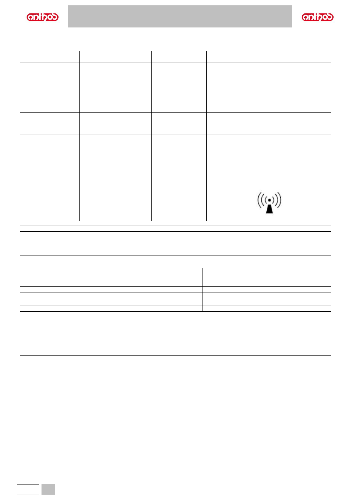
A5 - A6 PLUS - L6
86
EN
Guidance and Manufacturer's declaration - Electromagnetic immunity
The dental unit is designed to operate in the specified electromagnetic environment. The customer or user of the dental unit must
ensure that it is used in such environment.
Immunity test
IEC 60601-1-2
Test level
Level of
conformity
Electromagnetic Environment
The RF communication devices (portable and mobile)
must not be used at a distance from the dental unit and
its components, including cables, lower than the
recommended distance calculated using the
corresponding equation applicable to the transmitter
frequency.
Recommended distance.
Radiated RF
EN 61000-4-3
3 V/m
From 80 MHz to 2.7 GHz
IEC 60601-1-2
Test level
d = 1.2 x √P 80 MHz to 800MHz
d = 2.3 x √P 800 MHz at 2.7GHz
Conducted RF
EN 61000-4-6
3 V
150 kHz to 80 MHz
6V
ISM frequencies
IEC 60601-1-2
Test level
d = 1.2 x √P
Where P is the maximum output power of the
transmitter in Watt (W) according to the transmitter
Manufacturer, and d is the recommended distance in
metres (m).
The field intensity of the fixed RF transmitters,
determined based on an electromagnetic site, could be
lower than the conformity level in each frequency
interval.
Near the equipment with the following symbol
interferences can be caused:
Recommended distance between the RF portable and mobile communication devices and the dental unit.
The dental unit is intended for use in electromagnetic environment where RF irradiated disturbances are controlled. The customer or
the user of the dental unit can prevent electromagnetic interferences by ensuring a minimum distance between RF mobile and portable
(transmitter) communication devices and the dental unit as shown below, according to maximum power output of the communication
devices.
Transmitter maximum nominal output
(W)
Distance according the transmitter frequency
(m)
150 KHz to 80 MHz
d = 1.2 x √P
80KHz to 800MHz
d = 1.2 x √P
800 KHz to 2.7 MHz
d = 2.3 x √P
0.01
0.12
0.12
0.23
0.1
0.38
0.38
0.73 1 1.2
1.2
2.3
10
3.8
3.8
7.3
100
12
12
23
For transmitters having a maximum nominal output power not listed above, the recommended distance d in metres (m) can be determined using
the corresponding equation applicable to the transmitter frequency where P is the maximum output power of the transmitter in Watt (W) according
to the transmitter Manufacturer.
Note:
(1) At 80MHz and 800MHz it is necessary to apply the distance defined for the highest frequency interval.
(2) These guidelines cannot be applicable to all situations. The electromagnetic propagation is influenced by the absorption and reflection of
structures, objects and people.
Page 87
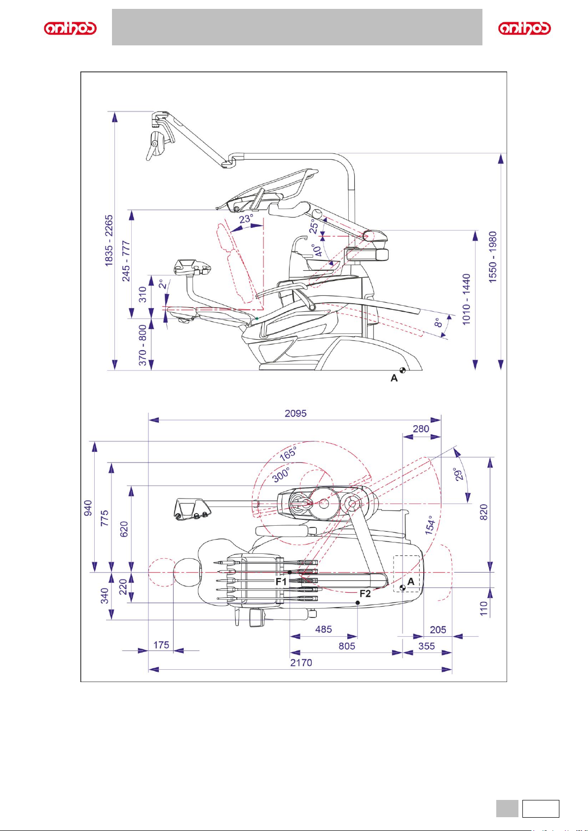
A5 - A6 PLUS - L6
EN
87
11.1. A5 CONTINENTAL DIMENSIONAL CHARACTERISTICS
Page 88
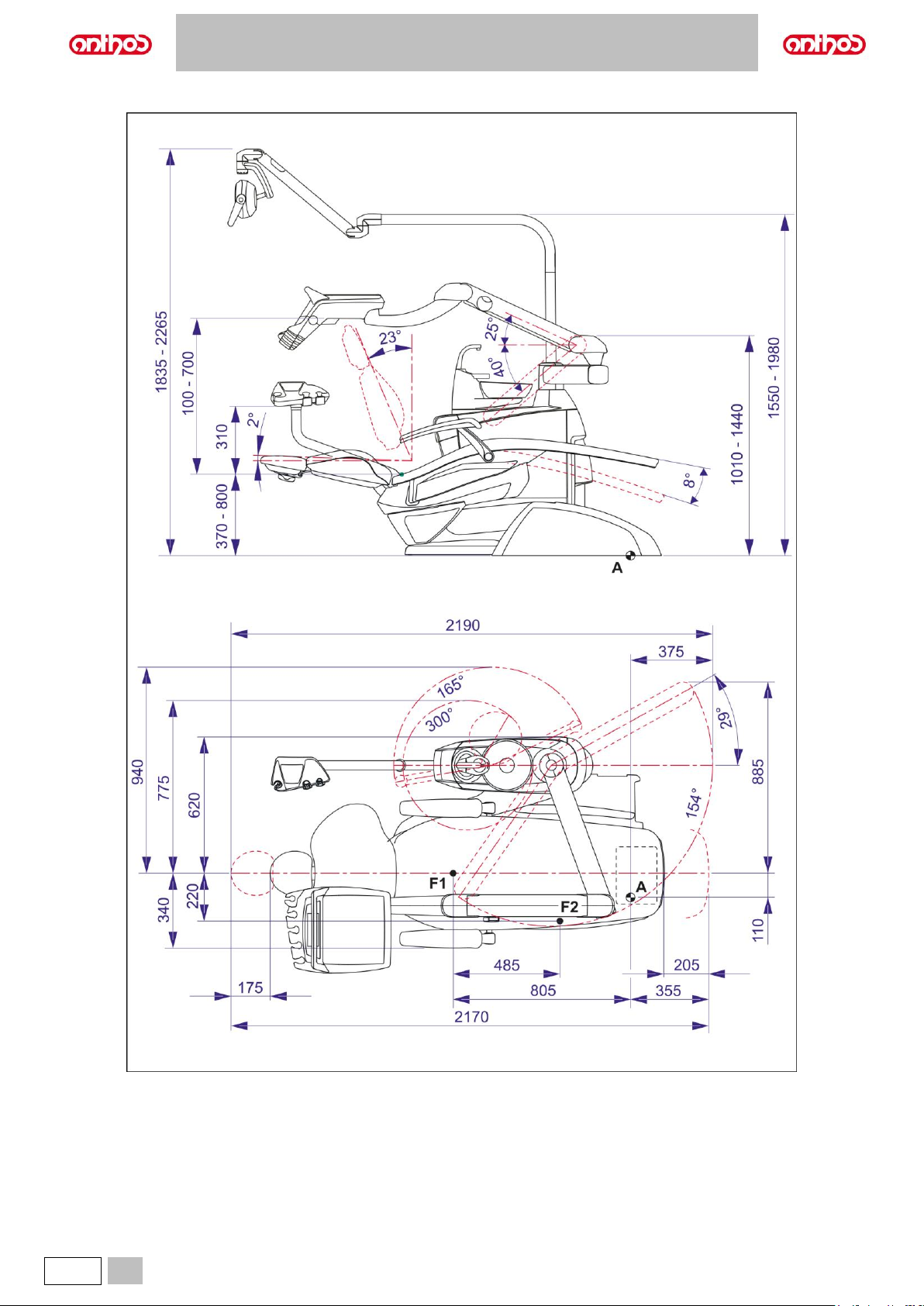
A5 - A6 PLUS - L6
88
EN
11.2. A5 INTERNATIONAL DIMENSIONAL CHARACTERISTICS
Page 89
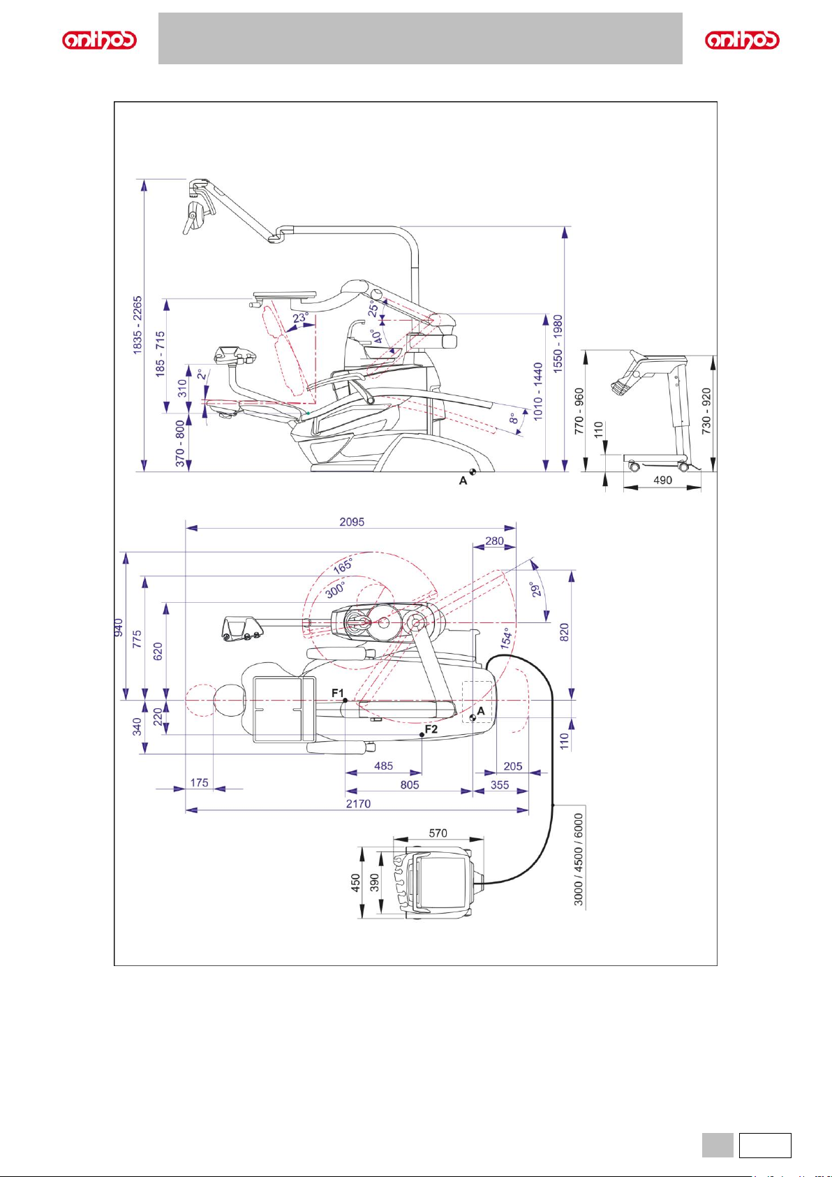
A5 - A6 PLUS - L6
EN
89
11.3. DIMENSIONAL CHARACTERISTICS OF A5 CART MODEL
Page 90
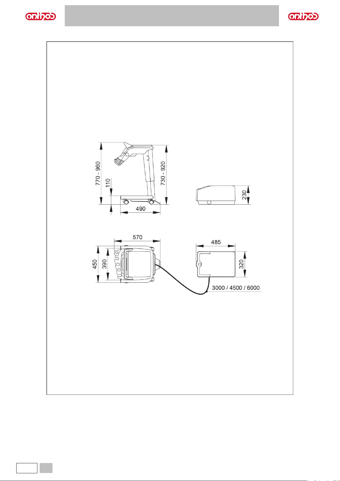
A5 - A6 PLUS - L6
90
EN
11.4. DIMENSIONAL CHARACTERISTICS OF A5 SINGLE CART MODEL
Page 91
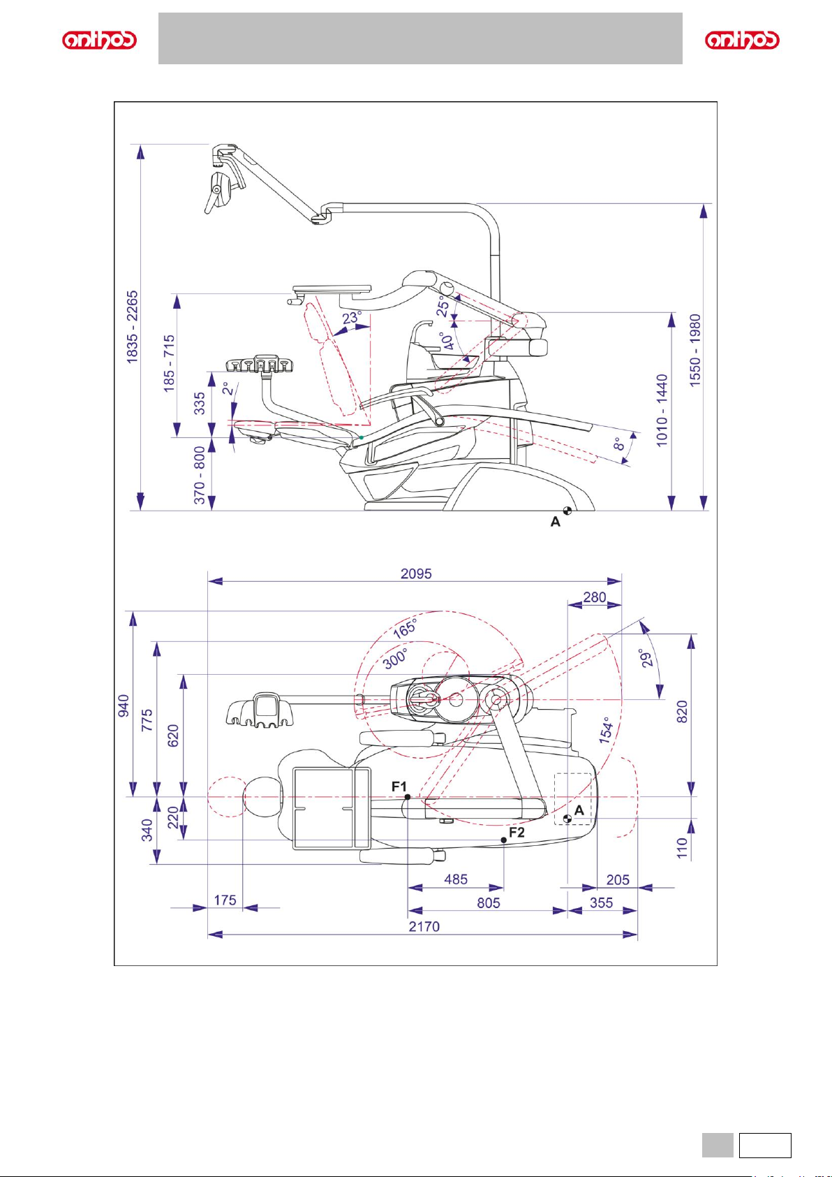
A5 - A6 PLUS - L6
EN
91
11.5. DIMENSIONAL CHARACTERISTICS OF A5 SINGLE WATER UNIT MODEL
Page 92
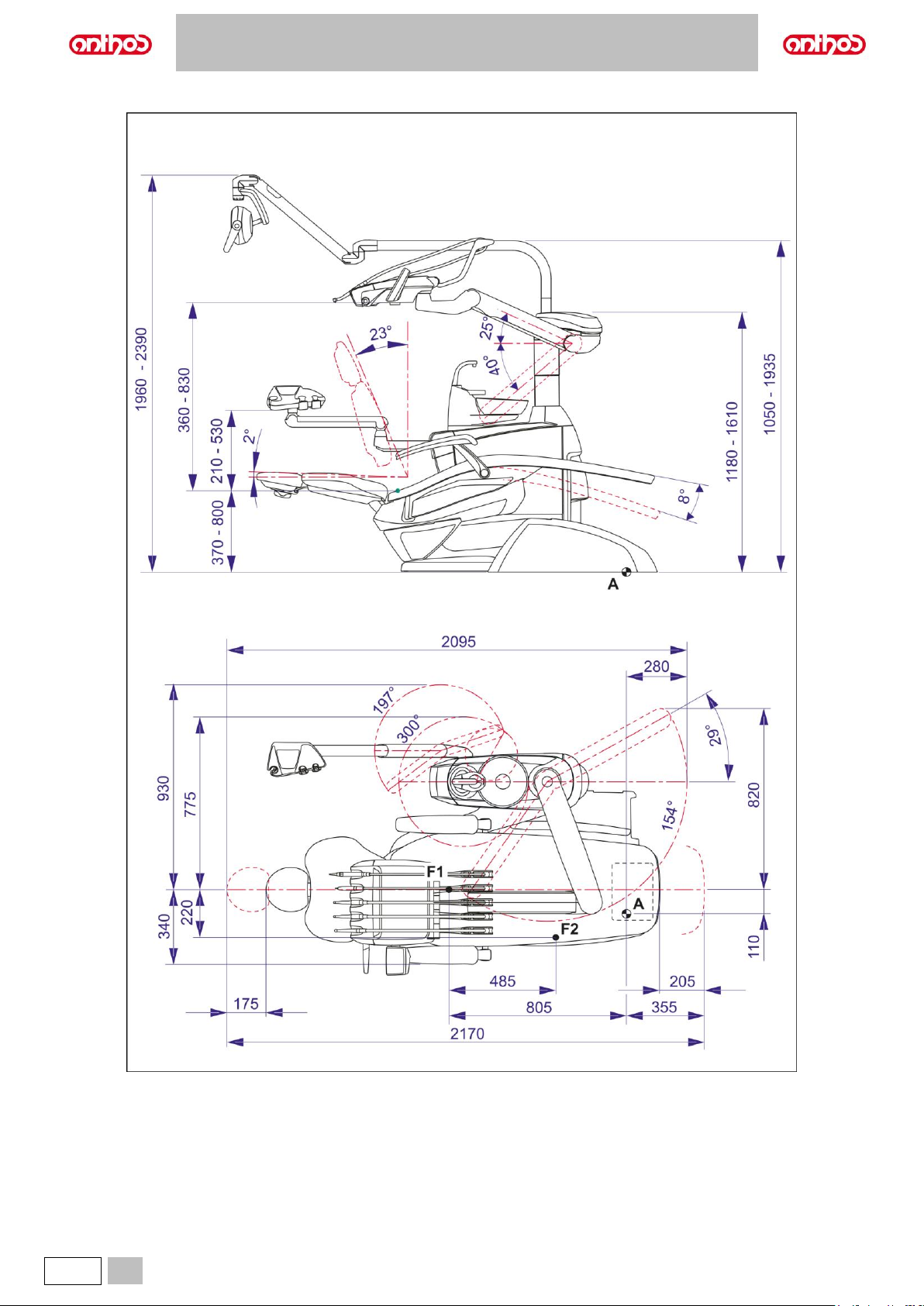
A5 - A6 PLUS - L6
92
EN
11.6. A6 PLUS CONTINENTAL MODEL DIMENSIONAL CHARACTERISTICS
Page 93
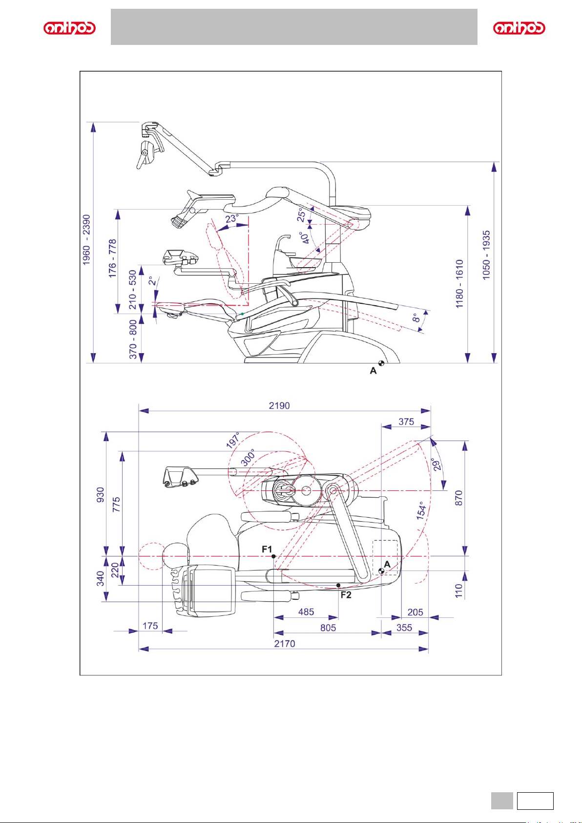
A5 - A6 PLUS - L6
EN
93
11.7. A6 PLUS INTERNATIONAL MODEL DIMENSIONAL CHARACTERISTICS
Page 94
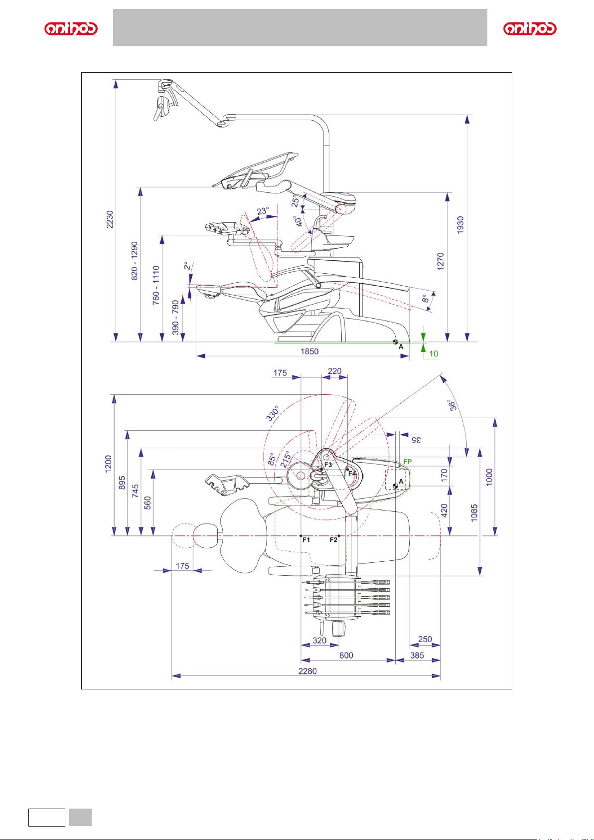
A5 - A6 PLUS - L6
94
EN
11.8. DIMENSIONAL CHARACTERISTICS OF L6 CONTINENTAL MODEL
Page 95
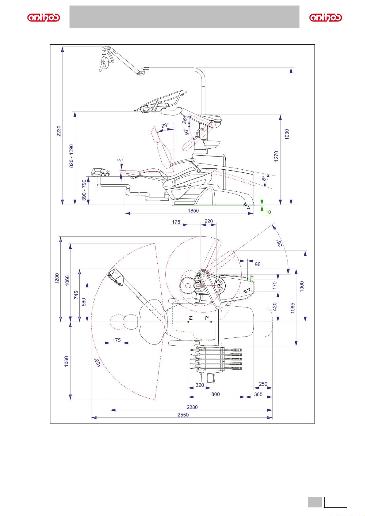
A5 - A6 PLUS - L6
EN
95
11.9. DIMENSIONAL CHARACTERISTICS OF L6 CONTINENTAL MODEL in HYBRID version
Page 96
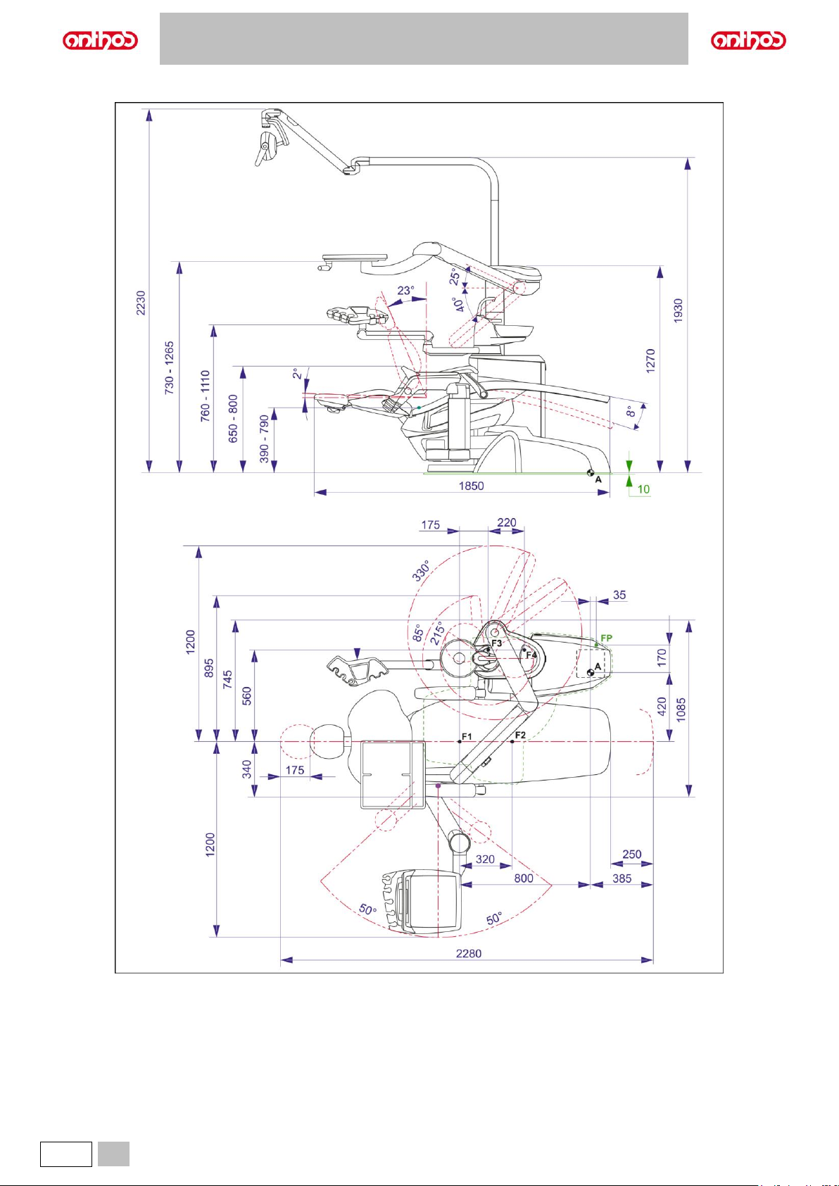
A5 - A6 PLUS - L6
96
EN
11.10. DIMENSIONAL CHARACTERISTICS OF L6 SIDE DELIVERY MODEL
Page 97
A5 - A6 PLUS - L6
EN
97
12. DENTAL UNIT MAINTENANCE SCHEDULE
WHEN
PART
ACTION
REFERENCE
PARAGRAPH
Daily activity
start.
Condensate drain cock.
Eliminate condensate from air ducts.
See paragraph 9.2.
Spray ducts
Duct 2-minute flushing
a) Manual: activate each instrument with no load
b) Automatic: activate the LONG FLUSHING cycle
See paragraph 7.5
Air-liquid separator canister by
CATTANI
Insert inside each suction filter a defoaming tablet.
See paragraph 9.5.
Disposable infection control sheaths.
Apply flexible sheaths and disposable barriers on
dental chair and dental unit.
/
Instruments.
Lubricate turbine and micromotor handpieces.
See documentation
enclosed with instrument.
W.H.E. system
(if the dental unit was left off for more
than 7 days)
Empty the W.H.E. system water circuit
See paragraph 7.3.
After each
patient.
Spray ducts.
20-second flushing of the instruments used on the
patient (Manual or QUICK FLUSHING)
See paragraph 7.5.
Instruments.
Disinfect outside.
See documentation
enclosed with instrument.
Camera.
Disinfect outside.
See paragraph 5.8.
Curing Light.
Disinfect outside.
See paragraph 5.7.
Suction tubes.
Carry out a STANDARD flushing cycle (if any) or suck
in about half a litre of 6% diluted STER 3 PLUS solution
with each of the suction tubes used.
See paragraph 9.4.
Flexible protections.
Sterilise the contaminated flexible protections.
/
Disposable barriers.
Replace disposable barriers.
/
Contaminated surfaces.
Clean surfaces with STER 1 PLUS.
/
Daily activity
end.
Spray ducts.
Disinfection of spray water ducts with manual cycle (if
the S.H.S. system is fitted).
See paragraph 7.2.1.
Disinfection of spray water ducts with semi-automatic
cycle (if the BIOSTER S system is fitted).
See paragraph 7.2.
Bowl filter.
Clean filter in running water.
The content must be disposed of separately.
See paragraph 7.1.
Bowl unit.
Clean with off-the-shelf detergents formulated for
ceramic materials.
Do not use acids or abrasive products.
See paragraph 7.1.
Suction filter.
Check filter and, in case suction capacity is reduced,
change it (code 97461845)
See paragraph 9.3.
Suction tubes.
Carry out an automatic flushing cycle (if any) or suck in
about half a litre of 6% diluted STER 3 PLUS solution
with each of the suction tubes used.
See paragraph 9.4.
Hydraulic saliva ejector.
Clean the filter of the saliva ejector terminal.
See paragraph 6.4.
Flexible protections.
Sterilise the present flexible protections.
/
Disposable barriers.
Eliminate all used disposable barriers.
/
Dental unit and chair surfaces.
Clean surfaces with STER 1 PLUS.
/
Page 98
A5 - A6 PLUS - L6
98
EN
WHEN
PART
ACTION
REFERENCE
PARAGRAPH
When needed.
Removable instrument hoses.
Clean with suitable disinfectant in compliance with
manufacturer's recommendations.
Spray product on disposable soft paper.
Do not use acids or abrasive products.
See paragraph 5.
Spray ducts.
Disinfection of spray water ducts with manual cycle (if
the S.H.S. system is fitted).
See paragraph 7.2.1.
Disinfection of spray water ducts with semi-automatic
cycle (if the system is fitted).
See paragraph 7.2.
Air-liquid separator canister by
CATTANI
Clean the separator’s container, drain valve and
probes.
See paragraph 9.5.
METASYS amalgam separator.
Empty separator container.
See documentation
enclosed with separator.
DÜRR amalgam separator.
Empty separator container.
See documentation
enclosed with separator.
Operating light
Clean the front lens and the reflector
See documents enclosed
with equipment.
VENUS PLUS-L LED operating light
Clean transparent screen and handles
See paragraph 8.1.
Monitor on light pole
Clean surfaces
See documents enclosed
with equipment.
Coated surfaces and upholstery.
Clean with suitable disinfectant in compliance with
manufacturer's recommendations.
Spray product on disposable soft paper.
Do not use acids or abrasive products.
See paragraph 1.4.
Weekly.
Suction tube holder terminals.
Lubricate the O-ring.
See paragraph 9.4.
Monthly.
Turbine return air filter.
Check the filter and replace it if necessary (code
97290014).
See paragraph 9.6.
Yearly.
Dental chair and dental unit.
Contact the Technical Service for general inspection.
/
Page 99

Page 100

www.cefla.com
 Loading...