

Page 1
Model ST3
VHF-Hi/UHF
Scanner Antenna
108-1300 MHz Range
20” Height
Accepts PL-259 Connector (not included)
Stainless-Steel
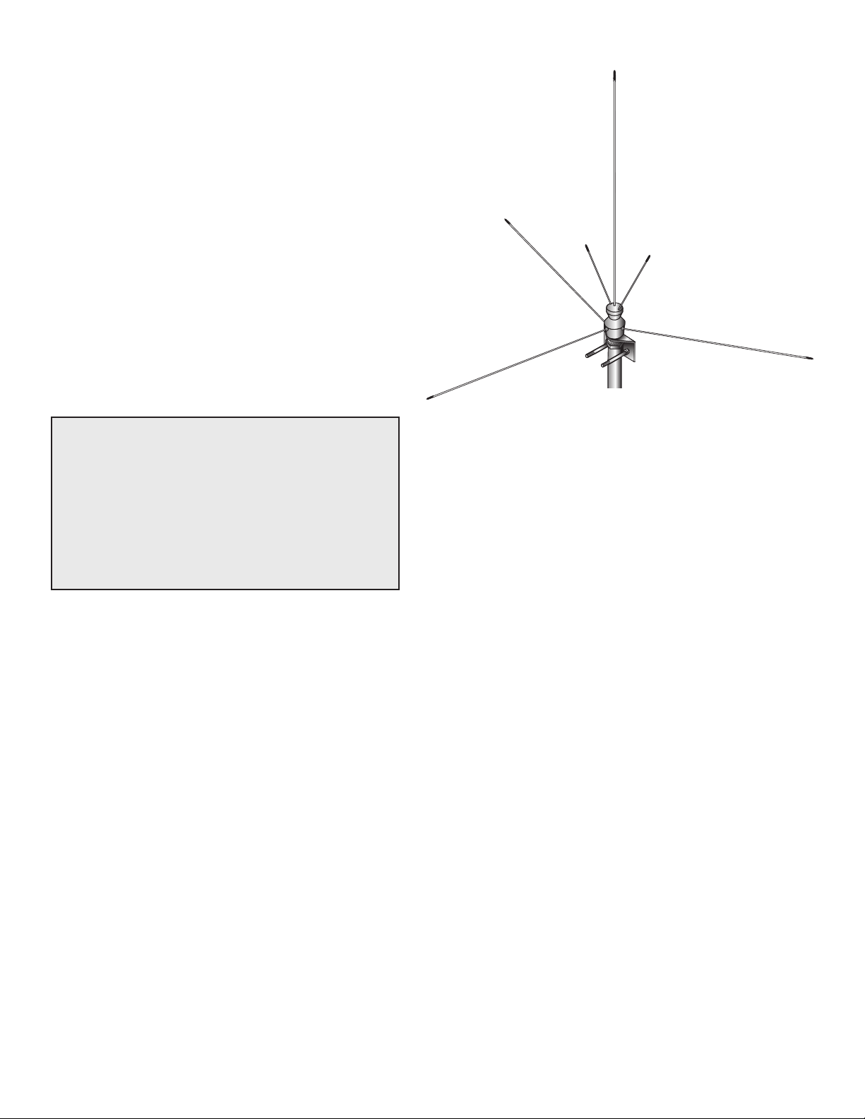
This outdoor VHF/UHF antenna covers from 108 to 1300
MHz. It uses three vertical radiators and three horizontal
radials, all stainless steel, with a chrome-plated brass ra-
diator assembly for efcient reception and lasting service.
WARNING: INSTALLATION OF THIS PRODUCT
NEAR POWER LINES IS DANGEROUS. FOR
YOUR SAFETY, FOLLOW THE INSTALLATION
DIRECTIONS.
If any metal antenna part touches a power line,
it completes a circuit path through anyone
touching the antenna. Power line voltage is lethal. You can be killed.
Before You Begin
Before you begin installation, read this manual and its
safety information. For your safety and convenience, plan
each step of the installation and purchase the necessary
hardware you will need in advance at your local electronics store. The order in which you perform the steps and the
hardware required depends on the mounting and connection methods you choose.
To prevent serious injuries and death, follow
these safety rules:
•
If you are not sure you can install the antenna safely, do not
try to do it yourself. Check the phone listings under Television Antenna Systems, or call your local power company.
• Assemble as much of the antenna as possible on the
ground.
• Watch for overhead power lines. Check the distance to
powerlines before you begin installing. We recommend
that you keep a minimum distance of twice the total
length of the mast and antenna assembly between your
antenna site and the nearest power line.
•
The antenna mast, cable, and guy wires all are excellent electrical conductors. Keep these away from power
lines.
• Do not use a metal ladder.
ST3
• Do not attempt installation on a windy day.
•
Have a friend act as a spotter when you are on the ladder
or on the roof. A spotter could see things you might not.
• If the antenna starts to fall, let go of it and let it fall.
• If any part of the antenna system touches a power line,
call your local power company and ask them to remove
it. Do not try to remove it yourself.
• Be sure your family and friends understand the danger
of touching overhead power lines. They should never try
to remove any object touching a power line.
If someone touches a power line:
• Do not touch anyone still in contact with the antenna or
the power line.
• Use a dry board, stick, or rope to move the antenna away
from the victim.
• If the victim stops breathing, administer articial respiration until help arrives.
• Have someone call for medical help
Where to mount your antenna
You can mount this antenna at a maximum height of 60 feet
above ground level, provided that:
• You locate the antenna more than 1¼ miles from the
nearest airport runway.
• The antenna site’s elevation above mean sea level is no
greater than that of the nearest airport.
•
If your site does not meet both of these conditions, do not
mount your antenna more than 20 feet above the ground.
•
Note: Refer to FCC Bulletin 1001H for further information.
• Mount your antenna where solid structural support is
available and where the incoming signal has minimum
interference. The best place is on a roof, with the mast
secured to a gable or chimney.
Note: Large amounts of smoke and soot can form depos-
its on the antenna, and lower its efciency. Check local
zoning ordinances for antenna installation regulations.
Page 2
Acceptable Types of Antenna Installations
1. Tripod: Use a 3-foot or 5-foot tripod bolted to a roof
or other sturdy mounting surface. Guy wires are not required.
2. Chimney Mount: Use heavy-duty chimney mounts,
straps, or brackets attached to the chimney or to a wall.
For safety, limit mast assembly to 10-foot or smaller.
Guy wires are not required.
3. Eave or Wall Mount: Use heavy-duty brackets attached to wood or masonry. The complete installation
must be able to support the antenna assembly, plus
wind pressure. For safety, limit mast assembly to 10-
foot or smaller. Guy wires are not required.
4. Guyed Mast: Use a heavy duty telescoping antenna
mast (not included) and guy wires (not included).
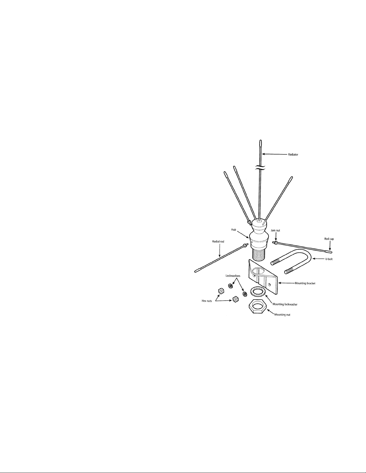
Assembly Instructions
1. Assemble the radial rods by screwing one jam nut on
the threaded end of each rod and placing one radial rod
cap on the opposite end of each rod.
2. Hand-tighten each radial rod into the hub of the radiator
assembly. Then, tighten the jam nut against the hub.
3. Place the radiator rod caps on the ends of the radiator
rods.
4. Attach the assembled antenna to the mounting bracket
with the mounting lockwasher and the mounting nut. Be
sure to tighten the mounting nut securely.
PARTS LIST:
DESCRIPTION ........QUANTITY INCLUDED
Radiator assembly .....................1
Radial rods ................................3
Mounting bracket .......................1
U-bolt .........................................1
Lockwashers..............................2
Hex nuts ....................................2
Jam nuts ....................................3
Mounting lockwasher .................1
Mounting nut ..............................1
Rod caps ...................................6
Warning label .............................1
Installation Instructions
1. Route coax cable (not included) from your receiver to
your antenna location.
2. Attach the antenna to the mast (not included) using the
U-bolt, hex nuts, and lockwashers. Be sure to tighten all
nuts securely.
3. Connect the coax cable to the antenna using a PL-259
connector (not included).
4. Fasten the coax cable to the mast with fasteners (available at your local electronics store) to avoid strain on
the cable connections.
5. Mount the mast at a location you have checked for
power line clearance.
6. Ground your antenna. Drive a ½” copper or steel rod
into the ground as close to the antenna base as possible. Connect an 8-gauge or larger copper or alumi-
num wire (available at your local electronics store) from
the antenna to the ground rod. Use the U-bolt as the
antenna grounding connections point.
7. Attach the warning label to the mast at eye level.
www.antennacraft.net
12/03/07
 Loading...