

Page 1
®
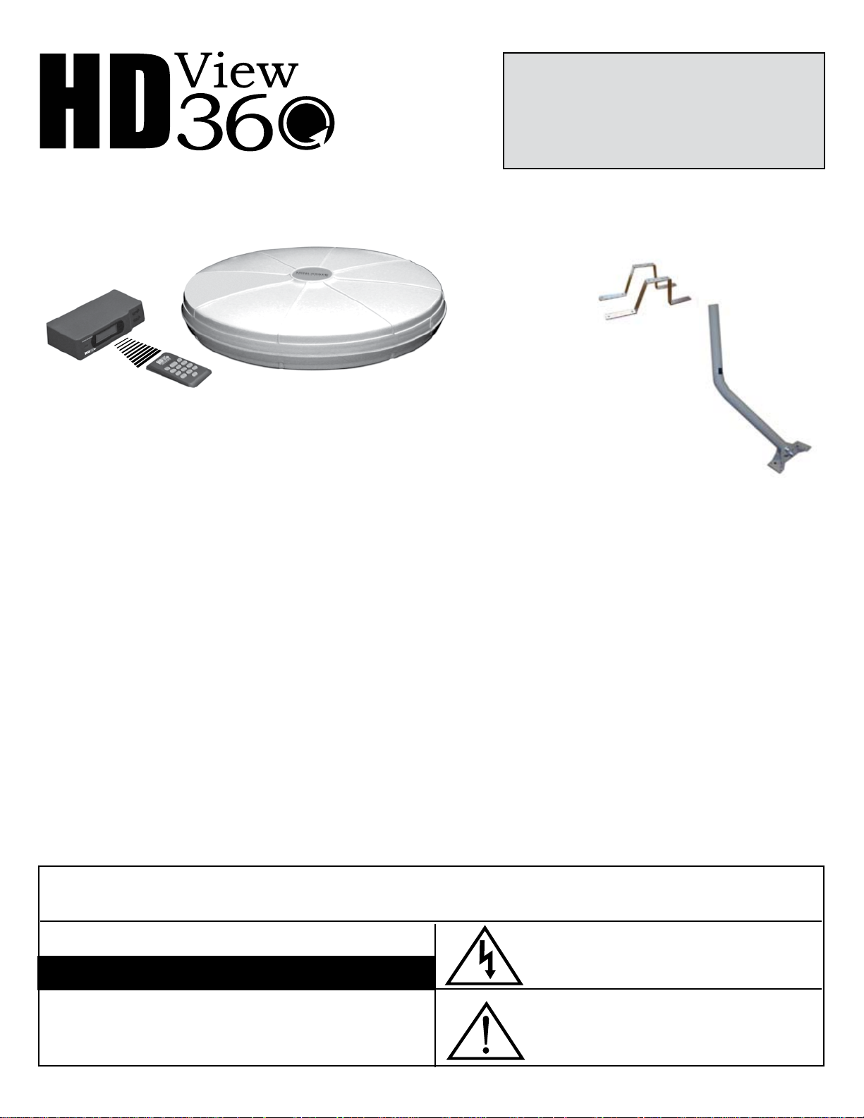
MINI-STATE® Antenna System
Model HDMS 9100
WARNING: INSTALLATION OF
THIS PRODUCT NEAR POWERLINES
IS DANGEROUS. FOR YOUR SAFETY,
FOLLOW THE INSTALLATION
DIRECTIONS.
Model HDMS 9100/RV includes two
RV/Boat mounting brackets.
• RV
• BOAT
• HOME
with RF remote and
Optional UAM9000
Offset J-Mount
Programmable, Direction Memory
Covered under one or more of the following U.S. Patents:
227,785; 3,721,990; 3,761,333; 3,909,691
© 2007 ANTENNACRAFT
IMPORTANT—This model is not compatible with Mini-State 5MS series motor drives.
Your Antennacraft HDView360® Mini-State® is perfect for
receiving off-air reception. You can store channel positions
with the Radio Frequency remote control, then later recall one
of the channel memories. Your antenna will automatically go
to the direction you programmed for your best reception.
The directional, rotating Antenna provides excellent reception
of HDTV/VHF/UHF TV channels in most viewing locations.
The UV protective housing is made of impact-resistant lled
co-polymer, making the exterior resistant to weathering. It
features both AC and DC operation and is excellent for use
on recreational vehicles, boats, or in the home.
Before Installation Note: to CATV SYSTEM INSTALLER—Article 820-40 of the NEC specied that the cable ground shall be connected to the grounding system of
the building “as close to the point of cable entry as practical”.
Note: Do not plug your Mini-State power supply into an AC outlet or DC power source until all electrical and antenna connections have been made. Doing so may short
out the power supply/transformer and void your warranty.
The VHF section is a circular shaped, slot tuned, broadband,
unidirectional traveling wave antenna. The UHF section is a
broadband, multi-element array. Both UHF and VHF signals
are amplied with a built-in split-band amplier that provides
up to 20 dB gain.
The HDView360 Mini-State Antenna System is designed for
long life and requires no routine maintenance. Should the
unit ever quit working, refer to the troubleshooting tips to
help determine possible causes. Do not attempt to service
this product yourself, as opening or removing covers may
expose you to dangerous voltage or other hazards. Refer
all servicing to qualied service personnel.
WARNING:
To reduce the risk of re or electric shock, do not expose this
appliance to rain or moisture.
CAUTION
RISK OF ELECTRIC SHOCK DO NOT OPEN
CAUTION: TO REDUCE THE RISK OF ELECTRIC SHOCK,
DO NOT REMOVE COVER (OR BACK).
NO USER-SERVICING. REFER ALL SERVICING TO
QUALIFIED SERVICE PERSONNEL.
CAUTION:
Use of controls or adjustments or performance of procedures other
than those specied may result in hazardous radiation exposure.
The lightning ash with arrowhead symbol, within an equilateral
triangle is intended to alert the user to the presence of uninsulated
“dangerous voltage” within the product’s enclosure that may be of signicant magnitude to constitute a risk of electric shock to persons.
The exclamation point within an equilateral triangle is intended to alert
the user to the presence of important operating and maintenance (servicing) instructions in the literature accompanying the appliance.
Page 2

IMPORTANT SAFETY INSTRUCTIONS
1. READ INSTRUCTIONS—All the safety and operating instructions should be read before the appliance is operated.
2.
RETAIN INSTRUCTIONS—The safety and operating instructions should be retained for future reference.
3.
HEED WARNING—All warnings on the appliance and in the
operating instructions should be adhered to.
4.
FOLLOW INSTRUCTIONS—All operating and use instructions
should be followed.
5.
WATER AND MOISTURE—The appliance should not be used
near water, for example—near a bathtub, washbowl, kitchen
sink, laundry tub, swimming pool, or in a wet basement.
6.
VENTILATION—The appliance should be situated so that its
location or position does not interfere with its proper ventilation.
For example, the appliance should not be situated on a bed,
sofa, rug, or similar surface that may block the ventilation openings; or, placed in a built-in installation, such as a bookcase of
cabinet that may impede the ow of air through the ventilation
openings.
7.
HEAT—The appliance should be situated away from heat
sources such as radiators, heat registers, stoves, or other appliances that produce heat.
8.
POWER SOURCES—This product should be operated only
from the type of power source indicated on the marking label.
If you are not sure of the type of power supply to your home,
consult your product dealer or local power company.
9.
GROUNDING OR POLARIZATION—This product is equipped
with a polarized alternating-current line plug (a plug having one
blade wider than the other). This plug will t into the power
outlet only one way. This is a safety feature. If you are unable
to insert the plug full into the outlet, try reversing the plug. If
the plug should still fail to t, contact your electrician to replace
your obsolete outlet. Do not defeat the safety purpose of the
polarized plug.
10.
POWER-CORD PROTECTION—Power-supply cords should
be routed so that they are not likely to be walked on or pinched
by items placed upon or against them, paying particular attention to cords at plugs, convenience receptacles, and the point
at which they exit from the appliance.
11.
CLEANING—Unplug this product from the wall outlet before
cleaning. Do not use liquid cleaners or aerosol cleaners. Use
a damp cloth for cleaning.
12.
ATTACHMENTS—Do not use attachments not recommended
by the product manufacturer as they may cause hazards.
13.
ACCESSORIES—Do not place this product on an unstable cart,
stand, tripod, bracket, or table. The product may fall, causing
serious injury to a child or adult, and serious damage to the
product. Use only with a cart, stand, tripod, bracket, or table
recommended by the manufacturer, or sold with the product.
By mounting of the product should follow the manufacturer’s
instructions, and should use a mounting accessory recommended by the manufacturer.
14.
POWER LINES—An outside antenna system should not be
located in the vicinity of overhead power lines or other electric
light or power circuits, or where it can fall into such power lines
or circuits. /when installing an outside antenna system, extreme
care should be taken to keep from touching such power lines
or circuits as contact with them might be fatal.
2
15. LIGHTNING—For added protection for this product during
lightning storm or when it is left unattended and unused for long
periods of time, unplug it from the wall outlet and disconnect
the antenna or cable system. This will prevent damage to the
product due to lightning and power-line surges.
16.
OBJECTS AND LIQUID ENTRY—Never push objects or any
kind into this product through openings are they may touch
dangerous voltage points or shortout parts that could result
in a re or electric shock. Never spill liquid of any kind on the
product.
17.
CARTS OR STANDS—If the appliance is used with a cart or
stand, the cart or stand should be a type recommended by the
manufacturer.
An appliance and cart combination should be
moved with care. Quick stops, excessive force, and
uneven surfaces may cause the appliance and cart
combination to overturn.
18. MOUNTING—The appliance should be mounted only as recommended by the manufacturer.
19. DAMAGE REQUIRING SERVICE—The appliance should be
serviced by qualied service personnel when:
A. The power-supply cord or plug has been damaged;
B. Objects have fallen onto, or liquid has been spilled into the ap
pliance enclosure;
C. The appliance has been exposed to rain.
D. The appliance has been dropped; or the enclosure damaged.
E. The appliance does not appear to operate normally or exhibits
a marked change in performance.
F. The product does not operate normally by following the operating
inscriptions. Adjust only those controls that are covered by the
operating instructions as an improper adjustment of other controls
may result in damage and will often require extensive work by
a qualied technician to restore the product to its normal operation.
20. SERVICING—Do not attempt to service this product yourself
as opening or removing covers may expose you to dangerous
voltage or other hazards. Refer all servicing to qualied service
personnel.
21. OVERLOADING—Do not overload wall outlets and extension
cords as this can result in a risk of re or electric shock.
22. REPLACEMENT PARTS—When replacement parts are required, be sure the service technician has used replacement
parts specied by the manufacturer or have the same characteristics as the original part. Unauthorized substitutions may
result in re, electric chock or other hazards.
23. SAFETY CHECK—Upon completion of any service or repairs
to this appliance, ask the service technician to perform safety
checks to determine that the appliance is in proper operating
condition.
24. OUTDOOR ANTENNA GROUNDING—If an outside antenna
or cable system is connected to the appliance, be sure the
antenna or cable system is grounded so as to provide some
protection against voltage surged and built-up static charges.
Section 810 of the National electrical Code, ANSI/NFPA No.
70-1984, provides information with respect to proper grounding
electrodes, and requirements for the grounding electrode. See
the example at the top of page 3.
-
Page 3
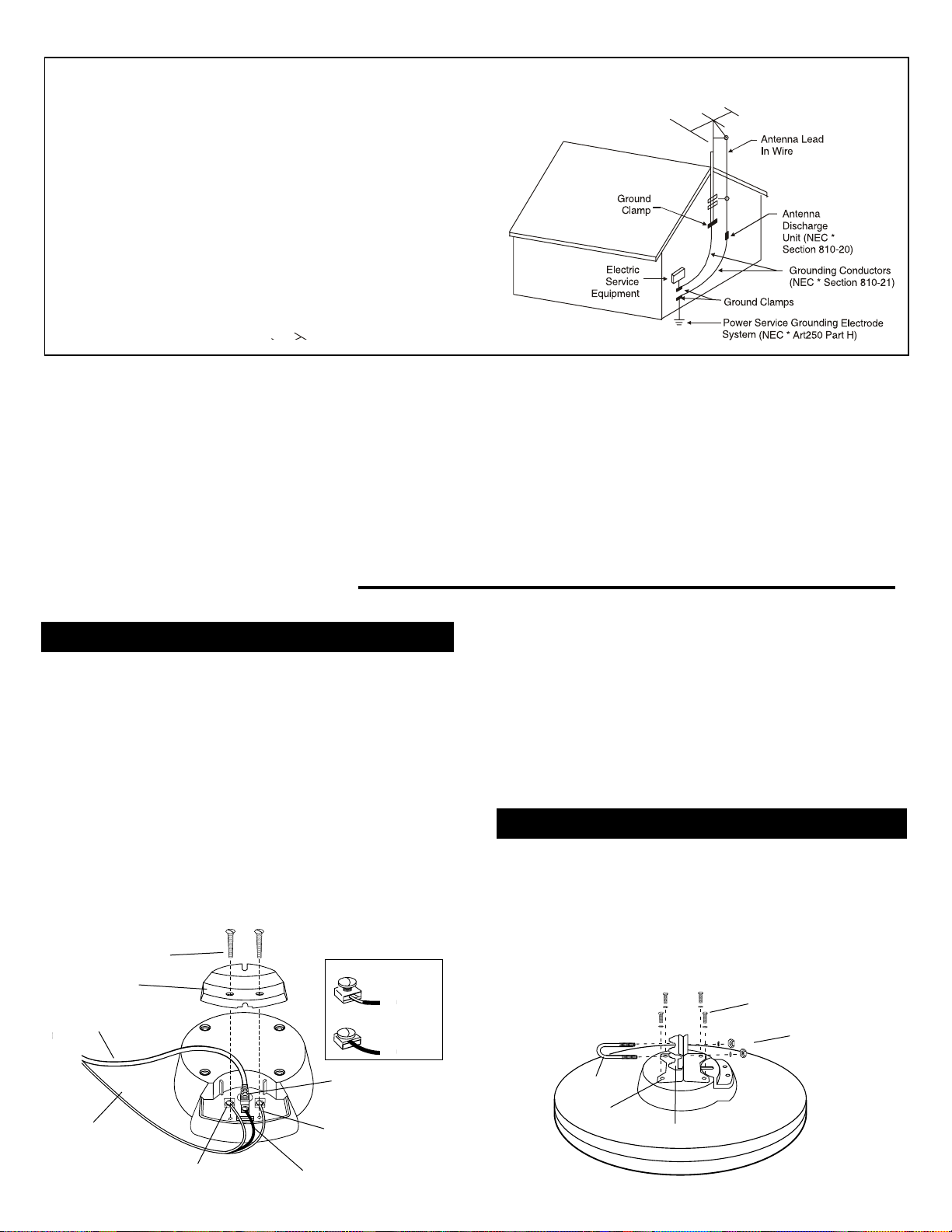
EXAMPLE OF ANTENNA GROUNDING ACCORDING TO
a
Use No. 10 AWG (5.3 mm2) copper, No. 8 AWG (8.4 mm2) aluminum, No. 17
AWG (1.0 mm2) copperclad steel or bronze wire, or larger, as a ground wire.
b
Secure antenna lead-in and ground wires to house with stand-off insula-
tors spaced from 4-6 feet (1.22-1.83 m) apart.
c
Mount antenna discharge unit as close as possible to where lead-in
enters house.
d
Use jumper wire not smaller than No. 6 AWG (13.3 mm2) copper, or the
equivalent, when a separate antenna-grounding electrode is used. See
NEC Section 810-21 (j).
a
Use No. 10 AWG (5.3 mm2) copper, No. 8 AWG (8.4 mm2) aluminum, No. 17
A
WG (1.0 mm2) copperclad steel or bronze wire, or larger, as a ground wire.
b
Secure antenna lead-in and ground wires to house with stand-off insula-
tors spaced from 4-6 feet (1.22-1.83 m) apart.
c
Mount antenna discharge unit as close as possible to where lead-in
enters house.
d
Any grounding electrode added for communications systems is required
to be bonded with a No. 6 AWG (13.3 mm2) or larger conductor to the
building or structure grounding electrode system in accordance with NEC
800.40(D), 810.21(J), 820.40(D) and 830.40(D).
NATIONAL ELECTRICAL CODE INSTRUCTIONS CONTAINED
IN ARTICLE 810-”RADIO AND TELEVISION EQUIPMENT”
Included in the HDView360 Mini-State Antenna
• HDTV/VHF/UHF antenna with amplier and internal
rotator
• RF remote and receiver
• 12VDC adapter with fused powercord
• 60' combination coaxial/3-wire rotator cable
• Stainless steel mounting hardware kit
• 12VDC power adapter
Installation of your Antenna
Connecting Cable to the Antenna
1. Loosen the two screws on the terminal board cover on the
bottom of the antenna. This will expose a threaded coaxial
receptacle and three special screw-type terminals.
2.
Screw the supplied coaxial cable’s lead-in connector onto the
threaded terminal. Caution: Be sure the center conductor of
the cable is in the hole of the F-connector before tightening.
3. Your antenna may have either Yellow/Black/White wires
or Red/Black/Blue rotator wires.
Note: Only loosen clamping terminals up to two turns, as
backing them out further can cause the screws to become
unattached from their internal mounts.
Terminal Board
Cover Screws
Terminal Board
Cover
Coaxial Cable
3-Wire
Rotator Cable
1
1
Yellow or Red Wire
3
2
2
Black Wire
Loosened
Terminal Screw
Tightened
Terminal Screw
Threaded Coax
Receptacle
3
White or Blue Wire
Specications:
Bandpass VHF ................................... 54-88, 174-216 MHz
Bandpass UHF ...............................................470-806 MHz
FM trap (xed) ........................... 88-108 MHz, 20 dB typical
VHF/UHF Gain ...................................................up to 20dB
Impedance ....................................... 75 Ohms, Unbalanced
Power Requirement ...................... 12VDC, 120 VAC, 60 Hz
Weatherproof housing ............. UV-protected, lled copolymer
Mounting .................................. 1½ inch (maximum) round mast
Specications are typical: Individual units may vary. Specications are
subject to change and improvement without notice.
Fasten the Yellow or Red rotator control wire to terminal
1, the Black wire to terminal 2, and the White or Blue wire
to terminal 3. Insert the wire between the upper and lower
clamps of the terminal body. Tighten the screw as shown.
4. Replace the terminal cover so that the coaxial cable comes
out through the notch. Tighten the terminal cover screws.
This will clamp the rotator cable in place.
Attaching the Mounting Bracket
1. Attach the antenna mounting bracket to the four slotted
metal inserts on the bottom of the antenna using the four
screws and lockwashers provided. (Do not unscrew recessed
metal inserts. They hold the internal motor in place.)
2. Insert the U-bolt into the mounting bracket using the two
washers and hex nuts. Do not tighten.
Screws and Lockwashers
Washers and
Hex Nuts
U-Bolt
Metal
Inserts
Mounting
Bracket
3
Page 4

Coaxial Cable
to TV
Cable
to Antenna
TV
ANT
Terminals
1–Yellow or Red
2–Black
3–White or Blue
3-Wire
Rotator
Cable
TV
1
2
3
DC 1 2V
ANTENNA CONTROL
for 12 VDC powerlead
or AC to DC adapter
Install
button-cell
battery
(included)
Back of
Remote Control
DIRECTION
Remote Control
Mounting the Antenna
Note: Mount the antenna before you make any receiver
connections and plug it into its power source.
Indoors—You can install the antenna on a vertical mast in
the attic, closet or other out-of-the-way location, or suspended
from an attic support with a wall-mount bracket. You can also
insert the three antenna legs into the matching holes on the
underside of the antenna so that they angle outward to form
a tripod support. Then place the antenna on a shelf in a closet
where it cannot fall or become damaged.
Outdoors—Install the antenna outdoors away from trees or
obstructions. (Higher frequencies are affected by obstructions.)
Mount the antenna on a mast and secure it by tightening the
hex nuts evenly onto the U-bolt. You can also use our off-set
J-Mount model UAM9000 (optional). Use a wall-thru tube to
neatly route the cable thru walls.
Make sure the installation of the antenna conforms to local
electrical and building codes, zoning requirements and other
Boat or RV—It is recommended that several locations be
tried to nd the one that provides optimum performance before
you permanently install the antenna.
Mount the antenna as high as practical and as far away from
metal objects as possible. If the interior areas of the vehicle
or boat are substantially enclosed or surrounded by metal
surfaces, an exterior mounting location must be selected.
For RVs with metal roofs, the antenna should be mounted at
least six inches above the roof surface. For boats, best reception will be obtained if the antenna is mounted above the boat’s
highest deck or cabin structure. RV/boat mount kits are available
to do these installations.
HDMS9100 Receiver Cable Connections
Note: Connect all wires and coax before plugging in the
receiver, so that the system can detect the antenna’s
position and rotate it accurately.
The coaxial cable provides feedback from your antenna.
If it has not been connected, your receiver may be permanently damaged!
1. Attach the coaxial cable’s downlead connector to the “ANT”
threaded coaxial terminal on the RF receiver unit, centering
the inner conductor in the hole before tightening the nut.
2.
Connect the wires as follows, and tighten the connections.
• Yellow or Red wire to Terminal 1
• Black wire to Terminal 2
• White or Blue wire to Terminal 3
3. Connect the receiver’s coaxial cable’s output to your TV’s
coaxial cable input.
Adjusting Your Antenna
A double-arrowhead is molded into the outer rim of the
antenna’s housing to indicate the antenna’s rotation. When
mounting the antenna in a residential or xed location, facing the double arrowhead toward the most often used TV
station will reduce the amount of rotation needed for best
reception.
For non-xed locations, such as RVs or boats, the antenna
may be installed with the double arrowheads facing in any
direction. Optimum TV reception may be obtained from any
location by orienting the antenna with its built-in rotator.
4
Installing the Battery
Your remote control is powered
with a button-cell battery (included). To install the battery:
1. Press and push open the
battery compartment cover.
2. Ins ert the CR2 032 bat -
tery (included) with positive
polarity (+) facing up, into
thecompartment and then
replace the cover.
Notes: Keep the button-cell battery away from small children.
If swallowed promply see a doctor.
Do not open the battery or dispose of it in a re, do not
recharge, do nor insert it upside down. It may explode or
leak, causing injury.
Use only fresh batteries of the same size and kind that are
included with the antenna.
If you do not plan to use your remote control for a week or
more, remove the battery. It can leak chemicals that can
cause damage to the electronic parts.
Page 5

Connecting to an AC or DC Power Source
Note: Do not plug your antenna’s power supply into an AC
outlet or DC power source until all receiver and antenna connections have been made. Doing so may
short out the receiver’s transformer and void your
warranty.
AC POWER—Plug the 12 VDC adapter into the DC jack on
the HDMS9000IR receiver. Plug the HDMS9000 AC
adapter into a 120-volt AC outlet near the TV.
DC POWER—Plug the 12 VDC adapter into the DC jack on
the HDMS9000IR receiver. Attach the red wire to the
positive terminal and the black wire to the negative
terminal of the DC source used. (The DC power cord’s
spade terminal ends can be removed if your installation requires another type of connector.)
Note:
The DC power cord contains an inline protective fuse.
For continuous protection against re hazard, replace
fuse only with the same type 0.75 ampere/250 volt
rating.
Finding and Storing Your TV Channels
Note: Make sure you have your antenna’s nal mounting
position before you plug in the receiver. If you relocate your
antenna’s outdoor or indoor position, make sure you unnplug
the receiver before you disconnect any wires or coax.
1. After plugging in the AC adapter or DC power souce,
the receiver will turn on. It will display “CA” and start
a calibration process.
2. The LCD backlight will also turn on for 1 minute. If the
receiver is idle for over 1 minute, the backlight will turn
off.
3. When the receiver receives signal from the remote
control, the indication LED light beside the LCD panel
will ash.
Note: This calibration process should be nished in less
than 2 seconds. During this process the antenna is
internally rotated and its existing position is noted.
Afterwards, it will stop at the last position shown on
the LCD of the receiver.
If the LCD keeps showing the “CA”, it means the cali-
bration process cannot be completed successfully. If
this happens, check the wire connections and see if
there is anything obstructing the antenna rotation.
4. The antenna’s direction can be changed step
by step by usin g the “UP” or “DOW N” ar row
buttons on the receiver ’s front panel or the left
or right arrow butto ns on the remote contr ol.
5. To continuously change the antenna direction, hold
down on the “UP” or “DOWN” arrow buttons on the
receiver or remote control.
6. To save the antenna direction for a channel, enter the
channel number with the remote control. Then, press
and hold the “STORE” button on the remote control
until the CH indicator on the receiver LCD ashes.
Use the left or right arrows on the remote to select the
optimized antenna direction. Finally, press “STORE”
again to save the setting.
8. To recall a stored channel and direction, enter the
channel number directly by using the number button
on the remote control. The antenna will then turn to
the direction that corresponds to the channel number
you entered on the remote control.
Changing the Transmitter/Receiver ID Code
Receiver ID code.
There may be cases that the receiver is triggered by
another transmitter in your neighborhood, or if you have
the antenna installed on your RV, and you’re where there
are other RVs with the same antenna.
If you nd the receiver is receiving and reacting to some
commands which have not been sent from your remote
control, try to change the Transmitter/Receiver ID code pair
following the below procedures:
1. Unplug the power cord from the receiver.
2. Hold down the ‘UP’ and ‘DOWN’ keys together and
power up the receiver until the LCD shows “Id” . The
receiver is now in the ID programming mode.
3. With the remote control near to the receiver, hold
down its ‘9’ and ‘0’ keys until the ‘Id’ on the receiver
LCD disappears.
4.
Press ‘1’, ‘2’, ‘3’ to select code 1, 2 or 3 respectively
within 2½ seconds after the receiver LCD is emptied.
5. The receiver should now show “x “, where “x” represents the Code number that you’ve set.
6.
Press the ‘STORE’ key on the remote control within 2½
seconds after pressing ‘1’, ‘2’ or ‘3’ for code selection.
7. The receiver should now show “Id x”.
8. The new ID code pair is stored. Unplug the receiver
and then plug it in again and for the new ID to be in
effect.
Note: You can use one of 3 identifying code numbers. The
default ID code used is 1.
1. After the ‘9’ and ‘0’ buttons on the remote control, are
released, then choose and press either the ‘1’, ‘2’ or ‘3’
keys within 2½ seconds. If button is pushed, it will exit
the ID programming mode. This is to avoid any accidental
button pushed on the remote control. If this happens, start
at Step 1 again.
2. After code number ‘1’, ‘2’ or ‘3’ is selected, users should
push the ‘STORE’ button on the remote control within
2.5 seconds. If no other button than ‘STORE’, ‘1’, ‘2’ or
‘3’ is pushed, it will exit the ID programming mode. This
is to avoid any accidental button pushed on the remote
control. If this happens, start at Step 1 again.
3. If the receiver is unplugged before it has been stored
(Step 8 above) the new ID code will not be saved.
Page 6

Trouble Shooting
The below provides information for problem diagnosis in case the antenna control system is not working properly. The receiver may sometimes display messages when its operation is interrupted.
Observation Possible Problem Actions
No Display on LCD No power connected.
The receiver is in ID programming mode and no
appropriate command is received from the remote.
LCD freezes with ‘CA’ upon
power up
LCD displays ‘Er’ The position feedback wire (black) is not connected.
LCD displays ‘Er’ and ‘CA’
during idle
LCD freezes during ID
programming
Receiver has no response to
the remote control
After changing the antenna
position, it returns to the
original number
The motor control wires (red, blue) are not connected.
The antenna rotation is obstructed.
The coaxial cable is not connected.
The 3 control wires (red, black, blue) are reversed.
Intermittent connection of the position feedback wire
(black).
The receiver is in ID programming mode and no
appropriate command is received from the remote.
The remote control is out of battery.
The ID code is mismatched.
The motor control wires (red, blue) are loosened.
The antenna rotation is obstructed.
Connect the power.
Power reset the receiver and
repeat the ID pair up.
Connect the wires*.
Clear the obstacles.
Connect the wire*.
Connect the cable*.
Correct the wire connection*.
Fix the wire connection*.
Power reset the receiver and
repeat the ID pair up.
Change the battery.
Pair up the ID code.
Fix the wires*.
Clear the obstacles.
* The receiver should be power reset after xing the wire connection.
The FCC Wants You to Know
This device complies with Part 15 of the FCC Rules.
Operation is subject to the following two conditions:
(1) this device may not cause harmful interference, and
(2)
this device must accept any interference received, in-
cluding interference that may cause undesired operation.
WARNING: Changes or modications to this unit not expressly approved by the party responsible for compliance
could void the user’s authority to operate the equipment.
NOTE: This equipment has been tested and found to
comply with the limits for a class B digital device, pursuant to Part 15 of the FCC rules. These limits are designed
to provide reasonable protection against harmful interference in a residential installation. This equipment generates, uses and can radiate radio frequency energy and, if
not installed and used in accordance with the instructions,
may cause harmful interference to radio communications.
However, there is no guarantee that interference will not
occur in a particular installation. If this equipment does
cause harmful interference to radio or television reception,
which can be determined by turning the equipment off and
on, the user is encouraged to try to correct the interference by one or more of the following measures:
□ Reorient or relocate the receiving antenna.
□ Increase the separation between the equipment and
□ Connect the equipment into an outlet on a circuit differ-
□ Consult the dealer or an experienced radio/TV techni-
receiver.
ent from that to which the receiver is needed.
cian for help.
Page 7

Available Parts:
5MS9000 Hand Control, 5MS9000 Power Supply,
5MS9000IRK Infrared Conversion Kit,
5MS9000 RV/Boat Mounts
30' Coaxial Cable, 60' Coaxial Cable,
RV/Boat Mounts (1 pair)
Do not service this product yourself, as opening or removing covers may expose you to dangerous voltage or other hazards.
Refer all servicing to qualied service personnel.
We warrant that if anything goes wrong with your ANTENNACRAFT HDView360 Mini-State Antenna within 90 days of purchase, and it is a manufacturing defect, we will repair the unit or replace it at no cost. This warranty excludes all costs arising from installation, removal, reinstallation or
setup, transportation to and from the dealer, and damage due to lightning, misuse or neglect. In addition, indirect, incidental, or consequential
damages are not covered. Some states do not allow the exclusion or limitation of indirect, incidental, or consequential damages, so the above
limitation or exclusion may not apply to you. To obtain warranty service, please do the following:
1. Take the unit to the dealer from which it was purchased or any ANTENNACRAFT Mini-State dealer.
2. Present your bill of sale or other evidence of the date on which the unit was rst purchased.
IT IS NECESSARY THAT YOU RETAIN YOUR BILL OF SALE OR PROOF OF PURCHASE IN ORDER TO OBTAIN WARRANTY SERVICE.
OUT-OF-WARRANTY SERVICE
In the event your ANTENNACRAFT Mini-State 5MS9000 should fail after the 90 day limited warranty period, the ANTENNACRAFT Service Center
will either repair the non-functioning unit at a cost to be determined by the Service Center and approved by you before the actual repair process
is started, or replace it with a remanufactured unit if available. The unit will be returned to you C.O.D.
When returning for repair:
1. Call 319-758-8050 for a Return Authorization Number
2. Package the unit properly to prevent damage
3. Ship prepaid to: ANTENNACRAFT,
1719 West Mount Pleasant Street
West Burlington, IA 52655
Please enclose your name, home phone number, daytime phone number, email address, return ship address, proof of purchase and a description of the problem. You
may be contacted by phone for more information about the antenna’s malfunction.
If the antenna is found not to be defective, there will be a fee of $20 for servicing
plus shipping costs.
www.antennacraft.net
 Loading...