

Page 1
Digital Ready
Note: This is a sample representation of your
antenna. To see your particular model, check
the end label on the antenna carton.
BEFORE YOU BEGIN
Read this manual and Consumer Product Safety Commission information.
For your safety and convenience, plan each step of the installation and
purchase the necessary hardware in advance. The order in which you
perform the steps and the hardware required depends on the mounting and
connection methods you choose.
We recommend two people assemble the entire antenna on the ground, then
mount the assembled antenna on the mast. The following steps are required
to assemble your antenna depending on which model you have. Look at your
antenna and the picture of the assembled antenna on the carton label.
Warning: When you install your antenna, use extreme cau-
tion. If the antenna starts to fall, let it go! It could contact
overhead power lines. If the antenna touches the power line,
contact with the antenna, mast, cable, or guy wires can cause
electrocution and death. Call the power company to remove
the antenna. Do not attempt to remove it yourself.
WARNING: Installation of this product near
powerlines is DANGEROUS. For your
safety, follow the installation directions.
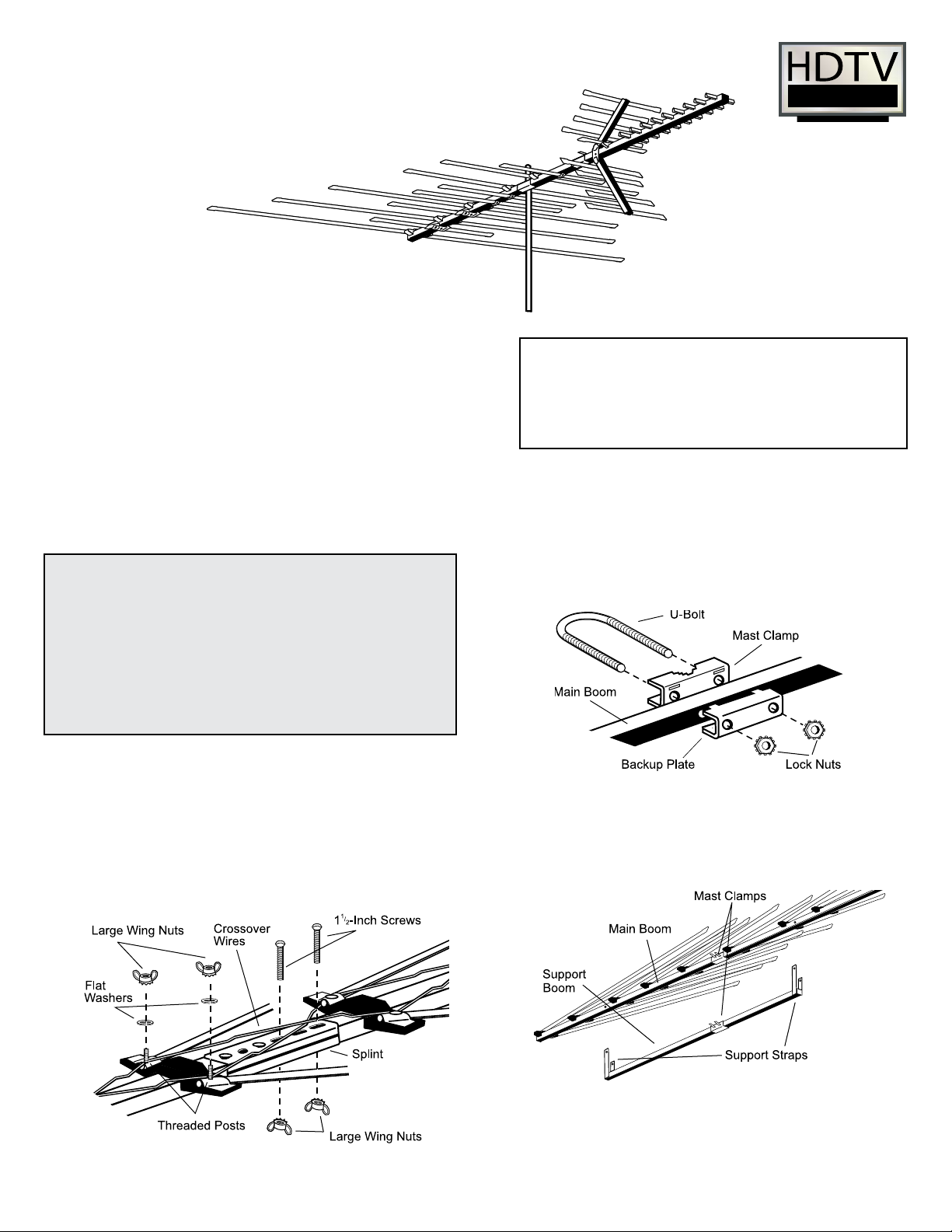
2. Use the supplied hardware to loosely attach the supplied mast clamp
assembly to the main boom as shown. If your antenna has a support
boom, attach its mast clamp assembly, facing it the same direction as
the main boom’s mast clamp assembly.
Note: Some antenna models may have the mast clamp
pre-attached.
ASSEMBLING THE ANTENNA
1.
If your antenna has more than one main boom section, use the supplied
splint hardware to assemble the sections as shown. If necessary, lift one
end of the main boom so the wires reach the threaded posts of the next
section.
Note: Some antenna models may have straight wires that connect
across the splint instead of crossover wires.
3. If your antenna has a support boom, align its support straps and mast
clamp with the main boom’s strap holes and mast clamp. You may have
to ip the support boom ends to get the correct hole alignment. Attach
the support straps to the main boom using the two supplied 1½-inch
screws and large wing nuts.
4. Press the supplied large end plugs into the main boom and support
boom. If your antenna has wing booms, press the supplied small end
plugs into the wing booms.
1
Page 2
Main Boom
Main
Support
Brackets
Support Boom
Delta Wings
Delta Wings
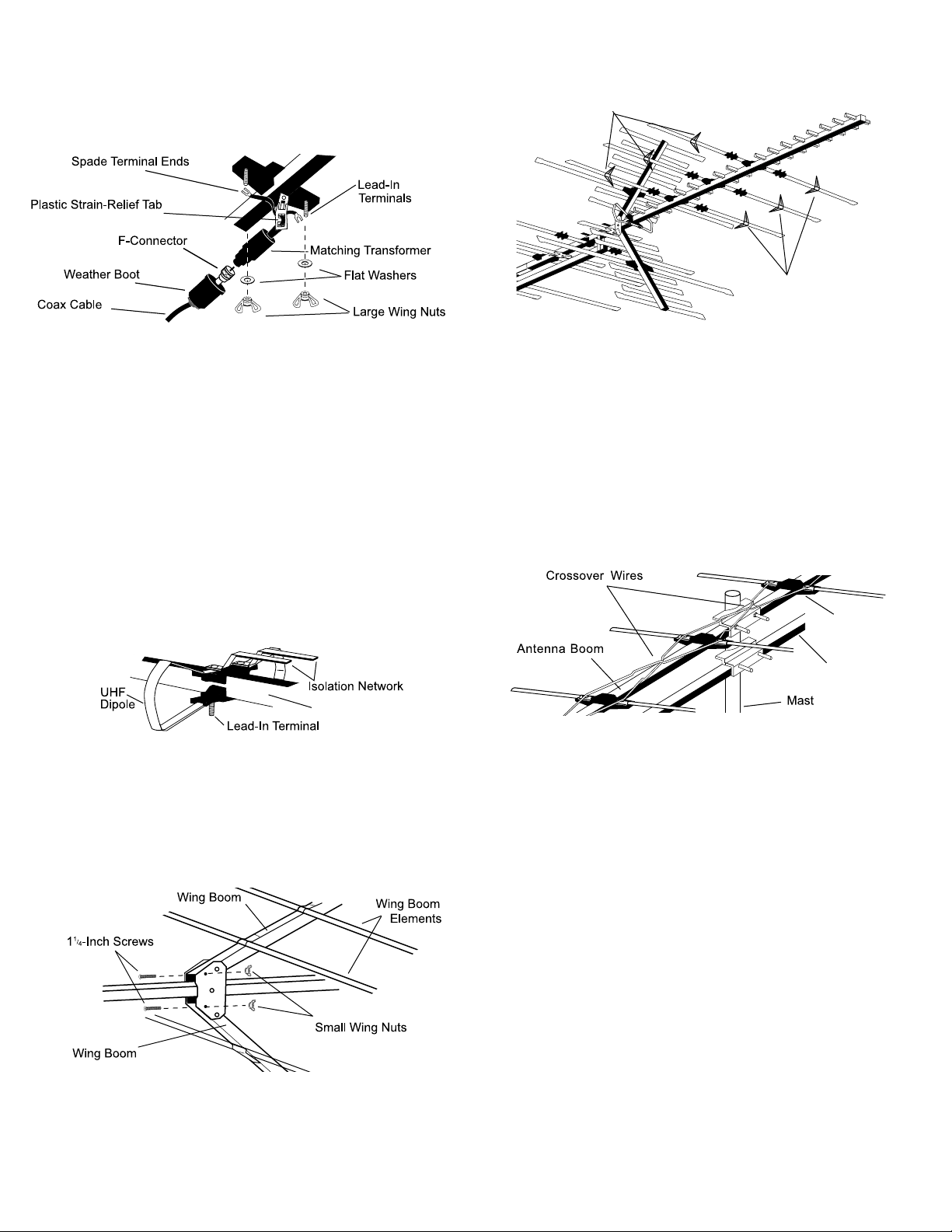
CONNECTING LEAD-IN CABLE TO THE ANTENNA
We recommend RG-6 cable, and if you prepare your own cable, a quality
F-connector.
Note: If you prepare your own cable, slide a 300 to 75 Ohm matching transformer’s weather boot onto the cable before you attach the F-connector.
1. Thread a 300 to 75 Ohm matching transformer’s spade terminal ends
through the antenna’s strain-relief tab.
2. Slide the spade terminal ends around the antenna’s lead-in terminals
marked CONNECT LEAD-IN HERE. Secure them with the supplied
at washers and large wing nuts.
3. Screw the cable’s F-connector onto the matching transformer. Then
slip the weatherboot over the connection.
Note: If you use a cable without a weatherboot, cover the connection
with weatherproof tape.
3. If your antenna has triangle shaped delta wings on some of the elements,
unfold each pair of them so that one wing points upward and one wing
points downward.
ATTACHING TO THE MAST
We recommend you get the help of another person before you put up the
mast or attach your antenna to it. How you set up your mast depends on
your specic installation.
Refer to the Consumer Product Safety Commission information on pages 3
and 4 of this manual for recommended methods.
1. With the antenna’s locking support brackets on top of the boom, slide
the antenna’s mast clamp assembly or assemblies over the top of the
mast. If your antenna has a support boom, make sure the main boom
is on top and the element’s support brackets are on top.
UNFOLDING THE ANTENNA ELEMENTS
1.
If your antenna has a UHF dipole, pull the dipole’s two halves from the
main boom until they lock into place. Place each unattached end over
each of the antenna’s lead-in terminals .
Note: Both sections of the isolation network should remain parallel to
the main boom.
2.
If your antenna has a UHF wing boom, hold each wing boom and turn
its elements until they snap squarely into place.
3. Fold out the wing booms and secure them into position with the two
supplied 1¼-inch screws and wing nuts.
4.
Hold the main boom’s elements near the pivot points and pull them away
from the boom until they snap into the locking support brackets.
Note: You may wait to unfold the elements until you get the antenna up on the
roof. Do not pull the elements near their outer ends or you could damage them.
Once the elements are locked into position, do not attempt to unlock them.
2.
Tighten the mast clamp assembly’s lock nuts to hold the antenna in place.
Do not overtighten the lock nuts.
Caution: The crossover wires must not touch the antenna boom, the
mast, or each other. If necessary, carefully bend the crossover wires to
provide at least 1/2 inch of clearance.
3. Set up the mast, then rotate it so the antenna’s shortest elements point
toward the stations you want to receive.
ROUTING THE CABLE TO YOUR RECEIVER
Use plastic tape to secure the coaxial cable to the mast at about 3-foot
intervals.
Use coaxial nail clips every few feet to secure the cable between the
mast and where the cable enters the house.
Use a 75-ohm grounding block at the point where the coaxial cable
enters the house. Read the Consumer Product Safety Commission
information for grounding instructions.
Use a drip-loop before the cable is routed into the house.
Use a wall-through tube to neatly route the coaxial cable through the
wall.
2
Page 3

WARNING: INSTALLATION OF
THIS PRODUCT NEAR
POWERLINES IS DANGEROUS.
FOR YOUR SAFETY, FOLLOW THE
INSTALLATION DIRECTIONS.
DANGER
FOLLOW THESE RULES AND LIVE
1. If you’re not sure about a careful, safe installation—don’t try to do it
yourself. Call your local power company or check with Yellow Pages
under “Antennas or Television and Radio Antenna Systems” for an
installer in your area.
2. With at least two people, assemble as much of the antenna on the
ground as possible.
3. Watch out for overhead powerlines. Check the distance to the pow-
erlines before you start installing—WE RECOMMEND YOU STAY A
MINIMUM OF TWICE THE MAXIMUM LENGTH OF THE ANTENNA
AND ITS MAST AWAY FROM ALL POWERLINES.
4. Do not use a metal ladder.
5. Remember, even the slightest touch of an antenna to a powerline can
cause a fatal shock.
6. Don’t try to do the job on a windy day.
7. Have a friend watch as a spotter on the ground when you’re on the roof
to see things you can’t.
8. If you start to drop the antenna, get away from it and let it fall.
9. If any part of the antenna comes in contact with a powerline—CALL
YOUR LOCAL POWER COMPANY; DON’T TRY TO REMOVE IT
YOURSELF! They will remove it safely.
10. Keep mast, lead-in and metal guy wires away from powerlines, too.
They are all excellent conductors of electrical current.
11. Be sure everyone understands the danger of touching an overhead
powerline. Tell them never to try to remove any object touching a
powerline.
12. Make sure that the antenna and its mast are properly grounded.
WATCH FOR POWERLINES!
You can be KILLED if this antenna
comes near electric powerlines.
READ INSTRUCTIONS.
IF AN ACCIDENT SHOULD
OCCUR WITH POWERLINES
1. Call for emergency help.
2. Don’t touch a person who has come in
contact with the antenna and the powerline (you’ll be electrocuted, too).
3. If the victim is free and clear from any
electric powerlines and is unresponsive, check their breathing and pulse.
If the victim is not breathing, admin-
ister articial respiration. If they have
no pulse, administer CPR until emergency help arrives.
HOW TO SELECT AND MEASURE YOUR
INSTALLATION SITE
Before attempting to install your antenna, think of where you can best place
your antenna for safety and performance. Most antennas are supported by
pipe masts attached to the chimney, roof, or side of the house. Generally,
the higher the antenna is above the ground, the better it performs. A good
practice is to install your antenna about 5 to 10 feet above the rooine and
away from powerlines and obstructions.
Remember that the FCC limits your antenna height to 60 feet. If possible,
nd a mounting place directly above your set, where the antenna lead-in
wire can take a short, vertical drop on the outside of the house for entry
through a wall or window near the set. To determine a safe distance from
wires, powerlines, and trees:
1. Measure the length of your antenna.
2. Add the antenna length to the height of your tower or mast.
3. Double this total for the minimum recommended safe distance.
If you cannot maintain this safe distance,
STOP! GET PROFESSIONAL HELP.
3
Page 4

CHOOSING A STRUCTURE MOUNT
Follow the installation directions for the individual type of mount you
choose.
4. IF YOUR MAST DOES NOT HAVE A DANGER LABEL, INSTALL
THE SELF-ADHERING DANGER LABEL PACKAGED IN ANTENNA
HARDWARE KIT AT EYE LEVEL ON YOUR MAST.
BA SE AN D ROO F
MO UNT: Mast l ocks
into U-bolt. Swivel base
fi ts the slo pe of most
rods.
VEN T PIPE MOUN T:
For smaller antennas. Attaches to vent pipe.
WALL MOUNTS:
Used on side of
structure.
CORNER MOUNTS:
Two Y-mounts with straps for
chimney corner mounting.
TRIPOD MOUNT: Sturdy
antenna mount for larger antennas
subject to stronger winds. Fits most
roof slopes.
UNIVERSAL MAST ANCHOR
MOUNT: Has U-bolt for easy swivel.
Adapts to most roof slopes.
EAVE MO UN T: For
attach ing antenna mast
to hanging rafters or trim
boards.
CHIMNEY RACHET
MOUNT: Provides secure
mounting to chimney with
straps.
TOWER: Not recommended, for professional
use only.
ANTENNA GROUNDING
To protect your house and your TV/FM installation, your antenna
system must be properly grounded.
1. Clamp a #10 copper or #8 aluminum grounding wire to the base of
thee antenna mast. Using stand-offs every 4 to 6 feet, run the wire
down the building in as straight a line as possible.
2. Attach a 300 ohm static discharge unit (lightning arrestor) or a 75 ohm
grounding block to the antenna’s lead-in cable as close as possible
to the point where the cable enters the house.
3. Attach the grounding wire to the lead-in cable’s grounding unit and
run the wire to the central building ground.
Acceptable central building ground points may include:
• Grounded interior metal cold water pipe within ve feet of the point
where it enters the building.
• Grounded metallic service raceway
• Grounded electrical service equipment enclosure
• 8-foot grounding rod driven into the ground (only if bonded to the
central building ground by #6 or heavier bonding wire)
• Other acceptable grounding electrodes that comply with sections
250 and 810 of the National Electrical Code (NEC)
ANTENNA REMOVAL
To remove the antenna, follow the instructions for installing the antenna,
but start with the last step rst. That’s the only safe way to remove an
antenna.
TELESCOPIC MAST: Has
interlocking sections.
GENERAL INSTALLATION DIRECTIONS FOR MAST
MOUNTED ANTENNAS
1.
Assemble your new antenna on the ground at the installation
site.Follow the separate assembly instructions that come with it.
2. Install the selected mount for your antenna.
3. Attach the mast and antenna to the mount.
Note: If you are going to use guy wires:
• Install guy wire anchor bolts
• Estimate length of guy wires and cut them
• Attach to mast using guy wire ring
• Have a second person hold the mast upright while the guy wires
are attached and tightened to the anchor bolts
7ALLCHANIS 507
www.antennacraft.net
4
 Loading...