

Page 1
Page 2

Isochrone OCX-V achieves the breakthrough clock stability by placing the quartz
crystal in an isolated, temperature controlled oven. Constant temperature control of the
crystal oscillator and a proprietary Jitter Management Module provide unprecedented
sonic benefits. Isochrone OCX-V takes the digital sound out of digital audio, giving you
the audio in its purest form whether connected to digital mixer, Pro-Tools system, DAW or
digital effects unit.
The amazingly stable Isochrone OCX-V can be taken to the ultimate level by locking it to
the most stable clock on Earth: the Atomic clock.
Designed for the modern studio and beyond, the Antelope's master clock provides the
most comprehensive video support in the industry. The OCX-V locks to PAL, NTSC, and a
staggering array of 20 HDTV standards. International pull ups and pull downs are also
supported.
With added flexibility of being able to output multiple sample rates and the built in support
for Pro Tools, Isocrone OCX-V easily surpasses the industry standard AardSync II, and is
destined to become the new Gold Standard.
Getting Started:
It takes only seconds to harness the benefits of the Isochrone OCX-V.
1
Connect the AC input to a power outlet.
2
If you plan on slaving to an external source, connect the master sync device to a
corresponding sync input on the on OCX-V rear panel. Set the SOURCE knob on front
to the input receiving incoming clock. If you are using OCX-V's internal clock, set
SOURCE to OVEN.
3
Connect any devices you want synced to the appropriate outputs on the OCX-V back
panel.
4
Power the OCX-V on via the power button on the front panel. Verify that both the
LOCK LED is lit, and that none of the red warning LEDs are flashing.
5
The OCX-V is now providing clock to connected devices. Some devices will
automatically sync to clock coming from the OCX-V. Other devices may require
additional configuration in order to utilize this incoming clock.
Note: When making initial connections, do so with the studio volume turned down.
Some devices may emit unpleasant sound until properly configured to accept incoming
clock.
Page 3
1 2
3
4
5
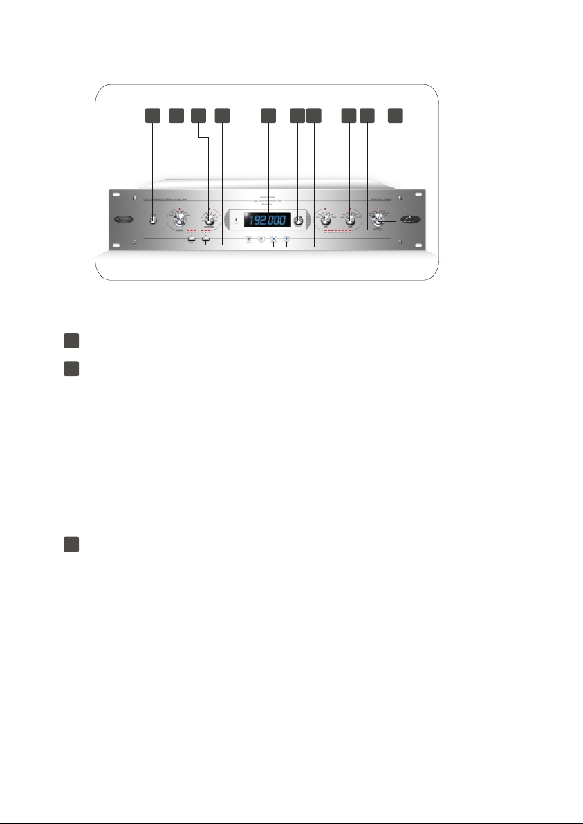
Front Panel
7
6
8
10
9
Front Panel
1
Power Switch
2
SOURCE Knob Designates which input the OCX-V receives its timing reference from.
The first five options correspond to physical inputs on the back of the unit. The final setting,
OVEN, configures the OCX-V to use its internal, oven controlled crystal oscillator as timing
reference, with one exception. The OVEN setting is also used to slave the OCX-V to
incoming atomic clock; the device will do so automatically, if an incoming atomic clock signal
is present.
Directly above the SOURCE knob is a red LED. When lit, it verifies a valid source signal is
present at the selected input. When flashing, it means the selected input is not receiving a
signal, or the incoming signal is not at a valid frequency.
More discussion about what constitutes a valid frequency is found in SAMPLE RATE Knob
section.
3
SAMPLE RATE Knob
Determines the frequency of the Word Clock, AES/EBU and S/PDIF outputs on the back of
the unit. The first seven choices are specific sample rates, which will be generated
regardless of the incoming reference frequency. When the sample rate does not match the
incoming reference frequency, the OCX-V operates in gearboxing mode, which is explained
in greater detail later in the manual.
The final setting of the SAMPLE RATE knob is DA (Distribution Amplifier). In the DA there is
no gearboxing functionality. The OCX-V simply takes the incoming audio clock selected by
the SOURCE knob, puts it through the Jitter Management Module to regenerate a clean,
de-jittered signal that is distributed to all audio outputs. In DA mode, the outgoing sample
rate will always match the incoming reference.
Page 4

The DA mode will not work if the SOURCE knob is set to VIDEO or OVEN, as there is no
audio reference to distribute. In this case the red LED above SAMPLE RATE knob will
flash. Note that in the DA mode, the OCX-V can work with non-standard sample rates as
may occur in vari-speed mode; any sample rate from 30 to 202 kHz is acceptable.
4
Pull up / Pull down Buttons
These buttons are used to modify the outgoing sample rate chosen with the SAMPLE
RATE knob. The first button accommodates the United States pull up / pull down standard,
increasing or decreasing the selected sample rate by 0.1 %. The second button
accommodates the European pull up/ pull down standard, increasing or decreasing the
selected sample rate by 4 %.
The rectangular LEDs above each button indicate whether the frequency is pulled up (+),
pulled down (-) , or not modified (0) by its corresponding button. You can always use the
Frequency Display window to see the actual frequency the unit outputs, with the pull ups /
pull downs selected at the moment.
Note that pull up / pull down feature is disabled when the SAMPLE RATE switch is set to
DA.
5
Frequency Display
Displays the sample rate outputted by the Word Clock, AES / EBU and S/PDIF outputs.
Word Clock outputs 7 and 8 are capable of providing fractional frequencies different from
the one displayed here. When the output frequency can not be generated during some
error conditions, the display will show "------".
6
Contrast Knob
Adjusts the contrast of the frequency display.
7
Status LEDs
LOCK , when lit indicates that the OCX-V is locked to a valid incoming reference.
ATOMIC, when lit, indicates that the OCX-V is slaving to external atomic clock.
OVEN, will flash when the OCX-V is first turned on, until the oven reaches its temperature
of operation. Once this temperature is achieved, the light will remain lit.
NTSC / PAL, will be lit if SOURCE is set to VIDEO, and the incoming video signal is either
NTSC or PAL format.
HDTV, will be lit if SOURCE is set to VIDEO, and the incoming video signal is a valid
HDTV format. See Appendix B for a a list of the supported HDTV formats.
Page 5

8 Alternate Sample Rate Selector for Word Clock outputs 7 and 8.
Word clock outputs 7 and 8 are capable of outputting frequencies different from the signal
on WC 1-6. The first five settings of the switch choose frequencies that are multiples of the
output frequency of the audio generator. The final setting, 256 WC, configures the output to
generate the 256 FS Clock, a protocol used by some Digidesign components. These
settings are summarized below:
WC/4 The output frequency is ¼ of WC 1-6
WC/2 The output frequency is ½ of WC 1-6
WC The output frequency is the same as on WC 1-6
2 WC The output frequency is 2x of WC 1-6
4 WC The output frequency is 4x of WC 1-6
256 WC The output is in Digidesign format, rate shown on the Frequency Display
A red LED is present above each knob. When lit, it indicates that a valid sample rate is
selected. When flashing, the output has been configured to output at a frequency outside
the supported range (30kHz- 202 kHz).
For easy reference, the following chart indicates what frequencies outputs 7 and/or 8
transmit depending on what sample rates and knob settings are chosen. Although the
OCX-V can generate any frequency between 30kHz and 202 kHz, this chart is limited to
those most commonly used. Note a setting that would produce invalid output is marked
With an 'x'.
ALTERNATE SAMPLE RATE
32 kHz
44.1 kHz
48 kHz
88.2 kHz
96 kHz
176.4 kHz
SAMPL E RATE
192 kHz
WC / 4
X
X
X
X
X
44.1 kHz
48 kHz
WC /2
X
X
X
44.1 kHz
48 kHz
88.2 kHz
96 kHz
WC
32 kHz
44.1 kHz
48 kHz
88.2 kHz
96 kHz
176.4 kHz
192 kHz
2 WC
64 kHz
88.2 kHz
96 kHz
176.4 kHz
192 kHz
X
X
4 WC
128 kHz
176.4 kHz
192 kHz
X
X
X
X
256 WC
256 fs
256 fs
256 fs
X
X
X
X
Page 6

Word Clock Termination Status LEDs
9
When lit, the corresponding Word Clock output is in use, and is properly
Terminated at 75 ohms. Blinking means the corresponding output is over-terminated.
Dark means the corresponding output is unused or is not terminated.
Video Generator knob
10
This knob selects the video signal provided by the four video outputs on the back of the
OCX-V. The first five choices provide different video standards.
PAL PAL Black Burst
PAL CB PAL Color Bars
NTSC NTSC Black Burst
NTSC CB NTSC Color Bars
NTSC BW NTSC Black and White mode (30 fps, color burst off)
The final option, DA (distribution amplifier), distributes an incoming video signal to the
four video outputs. The DA setting will only work if the SOURCE knob is set to VIDEO.
Like the output audio clock generator, the video generator is always phased-locked with
the input reference. For this locking to work the input reference has to be one of at a
valid rate. The red LED above the knob indicated the status of the video generator. If the
LED is flashing, the video generator is not able to lock to the incoming reference. This
situation can occur if the unit is locking to one of the audio references while in the DA
mode (SAMPLE RATE knob is set to DA) and the audio reference is not at a valid rate.
(Valid rates are listed in Appendix A).
Page 7

13 14 15 16 17 18 19 20 21
11 12
Rear Panel
Rear Panel
11
Power Connection
This IES AC connection accepts an input of 95-245 VAC 50/60 Hz. As a result,
the OCX-V automatically accommodates to the range of voltages found internationally,
permitting use in any country.
12
Word Clock input 1 and 2
BNC connections used to accept Word Clock reference.
13
AES/EBU Input and AES/EBU THRU
The AES/EBU Input is an XLR connection that accepts AES/EBU clock or audio. This signal
is buffered and made available at the AES/EBU THRU for chaining purposes.
Note that the signal at the THRU is not de-jittered by the Jitter Management Module; it is
simply a replica of the AES/EBU input.
14
S/PDIF Input and S/PDIF THRU
The S/PDIF Input is an RCA connection that accepts S/PDIF clock or audio. This signal is
buffered and made available at the S/PDIF THRU for chaining purposes. Note that the
signal at the THRU is not de-jittered by the Jitter Management Module; it is simply a replica
of the S/PDIF input.
15
Atomic Clock In and THRU
The Atomic Clock Input allows the OCX-V to operate with unprecedented accuracy.
This BNC input accepts the 10 MHz clock signal found an atomic clock device. This signal
Is buffered and made available at the Atomic THRU for chaining purposes.
Page 8

16
Video input and THRU
The video input is a BNC connection that accepts video reference, see appendix B for
supported formats. This signal is buffered and made available at the Video THRU for
chaining purposes.
Word Clock Outputs 1-6
17
The sample rate provided by these outputs always matches the sample rate indicated by
the Frequency Display on the front panel.
Word Clock Outputs 7-8
18
The sample rate provided by these two outputs can either match the sample rate of outputs
1-6, or can be changed to alternate sample rates by using their corresponding knobs
on the front panel.
AES/EBU Outputs 1-2
19
Provide AES/EBU clock at the sample rate shown in the Frequency Display on the front
panel.
S/PDIF Outputs 1-2
20
Provide S/PDIF clock at the sample rate shown in the Frequency Display on the front
panel.
Video Outputs 1-4
21
Provide video signal in the format selected by the VIDEO GENERATOR Knob.
Page 9
OCX-V GEARBOXING MODE
In Gearboxing Mode, the OCX-V always generates an output clock at the sample rate set
by the SAMPLE RATE knob, regardless of the incoming reference frequency. This output
clock is still phase-locked to the reference input, but the sample rates need not match.
For example, you may set the SAMPLE RATE knob at 48 kHz and apply a 44.1 kHz
reference. The device then "gearboxes" 44.1 kHz into 48 kHz output, as selected by the
SAMPLE RATE knob. This ability to lock to one sample rate and generate another is very
useful for sample rate conversions. Gearboxing Mode dramatically improves the sound
quality of sample rate conversions.
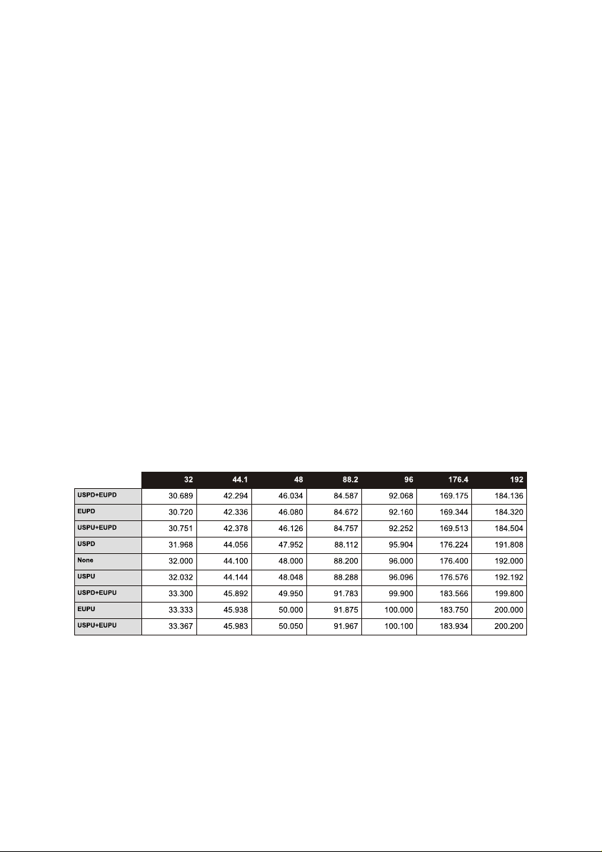
For Gearboxing to work, the incoming reference must be one of 63 recognized valid
frequencies. A valid frequency is i) one of the standard frequencies: 32, 44.1 48, 88.2, 96,
176.4, 196 kHz; ii) a standard frequency subjected to every possible combination of US
and Euro pull up/downs (9 combinations are possible). See Appendix A for a complete table
of all valid frequencies.
Table of valid input frequencies in Gearboxing Mode
Appendix A
Page 10

Table of valid input video formats
Appendix B
Page 11

 Loading...