

Page 1
U
SER’S
M
ANUAL
VP450 P
OWER SUPPLY
Page 2

U
SER’S
M
ANUAL
VP S
VP450 P
S
TRICTLY POWER
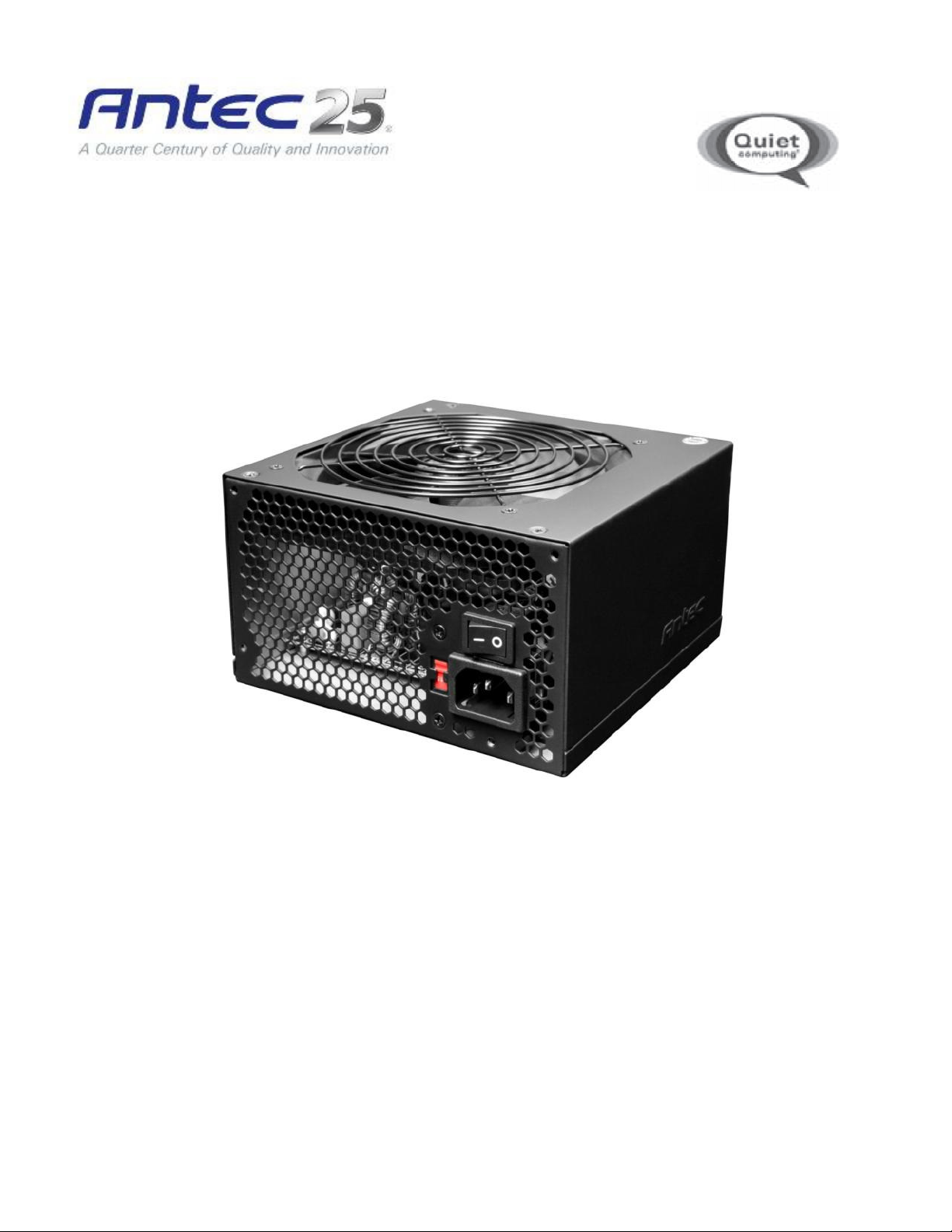
The VP450 is crafted for quality, performance and incredible value. This entry-level solution gives you
everything you need in a power supply. No twinkly lights or glittery paint jobs: a 120 mm fan for effective
and quiet cooling, dual +12V rails for amazingly stable power and heavy-duty protection circuitry for peace
of mind, no matter how demanding your system. And it comes with all the assurance of Antec’s AQ2 Antec
Quality 2 year limited warranty. All the features, none of the waste: for builders that are strictly business,
the VP450 is strictly power.
S
TANDARDS AND FEATURES
The connectors and power specifications of the VP450 PSU are all compatible with ATX12V v2.3 and EPS12V v2.91
specifications. The VP450 also features 450 watts of Continuous Power, the actual stable power a PSU can output
continuously at maximum load level.
S
YSTEM PROTECTION
A variety of industrial-grade safety circuitry will help protect your computer: OVP (Over Voltage Protection), SCP
(Short Circuit Protection), OPP (Over Power Protection) and OCP (Over Current Protection). Sometimes the PSU
will “latch” into a protected state. You will need to power off the PSU and clear the fault before it will function
again. There are no user-replaceable fuses in your VP450.
ERIES
OWER SUPPLY
P
OWER OUTPUT & CONNECTORS
The VP450 power supply distributes power on separate rails. Some rails require a minimum load in order to run. To
see the output capacity and regulation for each different voltage, see Table 1. A list of all available power
connectors can be found in Table 2.
T
ABLE
1
Output Voltage Load Max. Regulation Ripple & Noise
+3.3V 24A ±5% < 50 mV
+12V1 18A ±5% < 120 mV
+12V2 18A ±5% < 120 mV
+5VSB 2.5A ±5% < 50 mV
2
+5V 15A ±5% < 50 mV
–12V 0.3A ±10% < 120 mV
Page 3

T
ABLE
2
Quantity Connector Description Rail
1
1
1
4
4
1
24(20 + 4)-pin main connector
12V1
8(4 + 4)-pin ATX12V / EPS12V
12V2
6-pin PCI-E
12V1
SATA connectors
12V1
Molex connectors
12V1
Floppy
12V1
3
Page 4

I
either the top or bottom of
case manual if you are unsure where the power supply should be installed.
main power connector to your motherboard. If
pin attachment on the 24
pin section cannot be used in place of a 4
pin connector for the CPU. If your mother
some of the openings, we recommend that you remove the cover and use the 8
Please also refer to your motherboard user’s manual for any special instructions
your case with the four screws provided.
your motherboard uses a 20
pin socket with a cover on
pin connector.
NSTALLATION
:
1. Install the VP450 PSU into
2. Connect the 24(20+4)-pin
connector, detach the 4Note: The detachable 4-
Refer to your
-pin
-pin connector.
-pin +12V connector.
3. Connect the 8-pin or 4+4-
Note:
board has an 8-
.
4
Page 5

4. Connect the 6-pin PCI-E connector to your graphics card (if applicable).
5. Connect all Molex/SATA connector(s) to your hard drives, optical drives (CD/DVD/BluRay™) and other
accessories. Please note that some devices will use either the older 4-pin Molex connectors, while others will
use the newer 15-pin SATA connector. 4-pin Molex connectors have two black wires, a yellow, and a red. The
SATA connector has an additional orange power wire.
6. Connect your floppy drive (if present) using the supplied FDD connector shown in Table 2.
7. When you have all the connections secured, connect the AC power cord to the power supply AC inlet, making
sure the use the heavy-duty cord supplied with your VP450. Turn the switch on the PSU to the “|” position.
5
Page 6

Antec, Inc.
47900 Fremont Blvd.
Fremont, CA 94538
tel: 510-770-1200
fax: 510-770-1288
Antec Europe B.V.
Stuttgartstraat 12
3047 A Rotterdam
Netherlands
tel: +31 (0) 10 462-2060
fax: +31 (0) 10 437-1752
Technical Support:
US & Canada
1-800-22ANTEC
customersupport@antec.com
Europe
europe.techsupport@antec.com
www.antec.com
© Copyright 2011 Antec, Inc. All rights reserved.
All trademarks are the property of their respective owners.
Reproduction in whole or in part without written permission is prohibited.
6
 Loading...