

Page 1
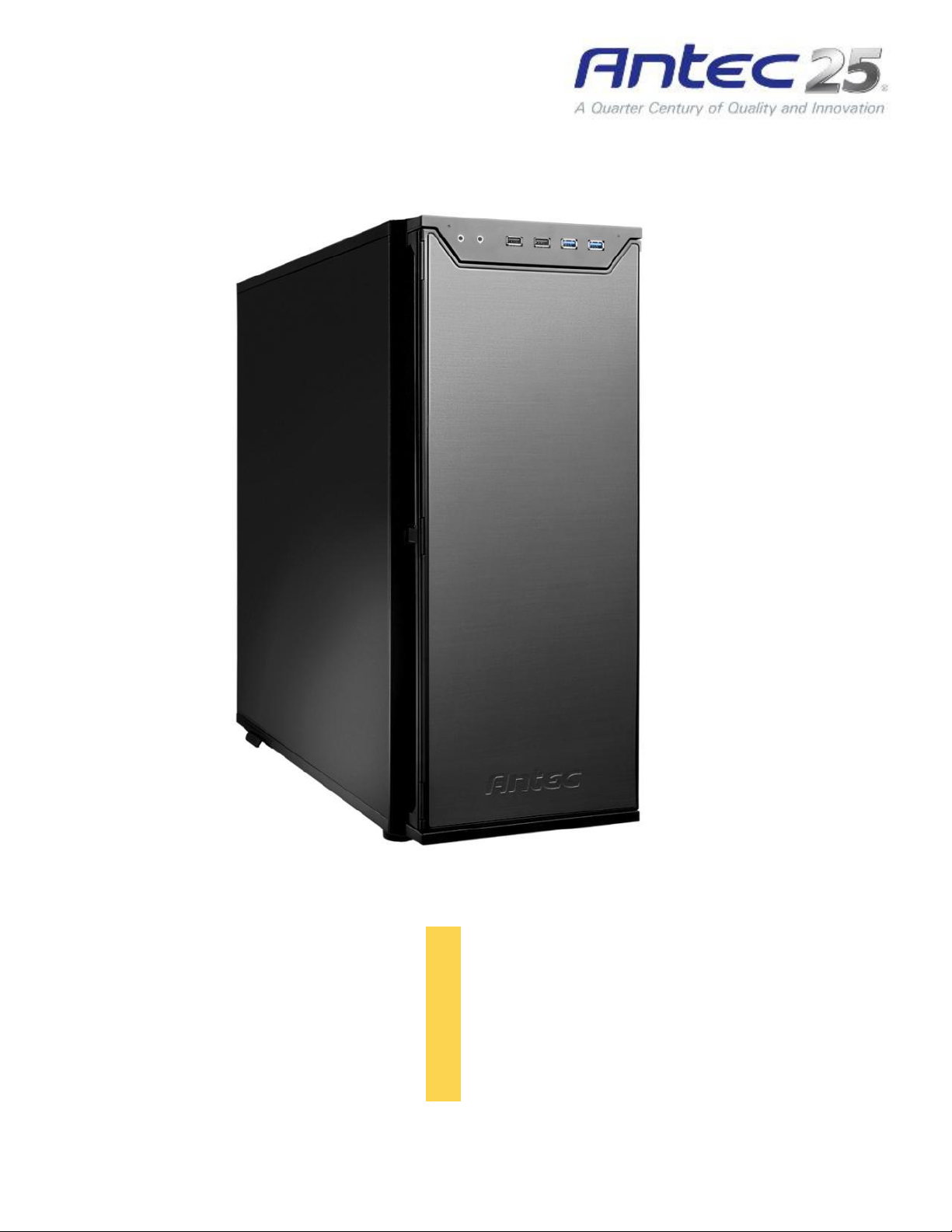
P280
User
Manual
Page 2

P280 User Manual
Disclaimer
Congratulations on your purchase of the Antec P280.
Sophisticated and cutting-edge, the P280 emphasizes the ease of use, quiet technology and unparalleled
performance characteristic of Antec’s Performance One series. This advanced enclosure comes
equipped with features that will maximize your PC experience, from Quiet Computing™ panels & HDD
drive bays, to grommet-lined cable routing holes with ample space behind the motherboard tray. The
P280 accommodates motherboards up to XL-ATX and includes nine expansion slots to support up to four
13.0” / 330 mm graphics cards. And with convenient tool-less optical drive bays, easy-access front &
bottom PSU intake air filters, two front panel USB 3.0 ports and an affordable price, you get an elite
enclosure that will last you for builds to come.
The P280 does not include a power supply. Make sure you choose a power supply that is compatible
with your computer components and has a long enough power harness to reach your motherboard and
peripheral devices. We recommend our High Current Gamer, High Current Pro or EarthWatts power
supplies for the latest ATX specification compliance, broad compatibility, and power savings capability.
At Antec, we continually refine and improve our products to ensure the highest quality. As such, your
new chassis may differ slightly from the description in this manual due to improvements applied for the
optimal building experience. As of November 15, 2011, all features, descriptions, and illustrations in this
manual are correct.
This manual is intended only as a guide for Antec’s computer
enclosures. For more comprehensive instructions on installing the
motherboard and peripherals, please refer to the manuals that
come with those components.
2
Page 3

Table of Contents
Section 1: Introduction
1.1 Getting to Know Your Chassis ............................................................................ 5
1.2 Chassis Specifications......................................................................................... 6
1.3 Included Screws ................................................................................................. 6
1.4 Before You Begin ................................................................................................ 7
Section 2: Hardware Installation
2.1 Setting Up .......................................................................................................... 9
2.2 Motherboard Installation................................................................................... 9
2.3 Installing KUHLER H2O Liquid Coolers ................................................................ 11
2.4 Power Supply Installation .................................................................................. 12
2.5 External 5.25” Device Installation ...................................................................... 13
2.6 Internal 2.5” Device Installation ........................................................................ 14
2.7 Internal 3.5” / 2.5” Device Installation .............................................................. 14
2.8 Cable Management ............................................................................................ 16
Section 3: Front I/O Ports
3.1 USB 2.0 ............................................................................................................... 18
3.2 USB 3.0 ............................................................................................................... 18
3.3 AC’97 / HD Audio Ports ...................................................................................... 19
3.4 Power Switch / Reset Switch / Hard Disk Drive LED Connectors ....................... 19
3.5 Rewiring Motherboard Header Connections ..................................................... 20
Section 4: Cooling System
4.1 Included Fans ..................................................................................................... 22
4.2 Optional Fans ..................................................................................................... 22
4.3 Air Filters ............................................................................................................ 24
3
Page 4

Section 1
Introduction
P280 User Manual
4
Page 5
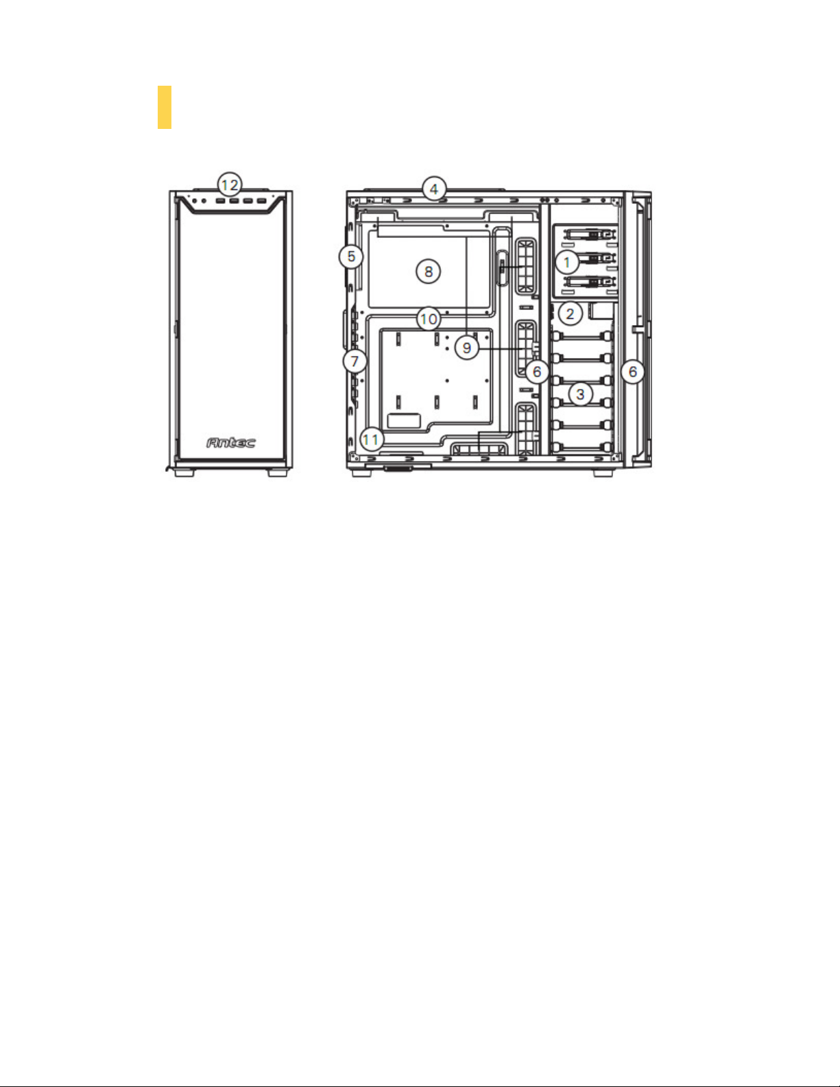
1.1 Getting to Know Your Chassis
1. 3 x 5.25” tool-less drive bays
2. 2 x 2.5” drive trays (dedicated)
3. 6 x 3.5” / 2.5” drive trays
4. 2 x 120 mm top TwoCool™ exhaust fans
5. 1 x 120 mm rear TwoCool™ exhaust fan
6. 2 x 120 mm internal intake fans (optional)
2 x 120 mm front intake fans (optional)
7. 9 expansion slots
8. CPU cutout
9. Cable routing holes
10. Motherboard mount: XL-ATX, Standard ATX, microATX or Mini-ITX
11. Power supply mount / PSU intake filter
12. Front Ports (USB 3.0, USB 2.0, Audio I/O)
5
Page 6
1.2 Chassis Specifications
Chassis Type
Super Mid
-
Tower
Chassis Color
Black w
ith aluminum
door
Dimensions
20.7” (H) x 9.1” (W) x 22.1” (D)
Weight
22.3 lbs /
10.2 kg
Cooling
-
2 x 120 mm top TwoCool™ exhaust fans
Drive Bays
-
3 x 5.25” tool
-
less drive bays
Expansion Slots
9: supports up to 3
-
way NVIDIA® SLI® / AMD CrossFireX™
Motherboard Size
XL-
ATX [13.6”
x 10.3” (345 mm x 262 mm)], Standard ATX, microATX, Mini
-
ITX
Front I/O Panel
-
2 x USB 3.0 with internal motherboard connector
A B C D E F G
526 mm (H) x 231 mm (W) x 562 mm (D)
- 1 x 120 mm rear TwoCool™ exhaust fan
- 2 x 120 mm internal intake fans (optional)
- 2 x 120 mm front intake fans (optional)
- 6 x 3.5” / 2.5” drive trays
- 2 x 2.5” drive-bays (dedicated)
- 2 x USB 2.0
- Audio In/Out
- Power and Reset buttons located on top panel of chassis
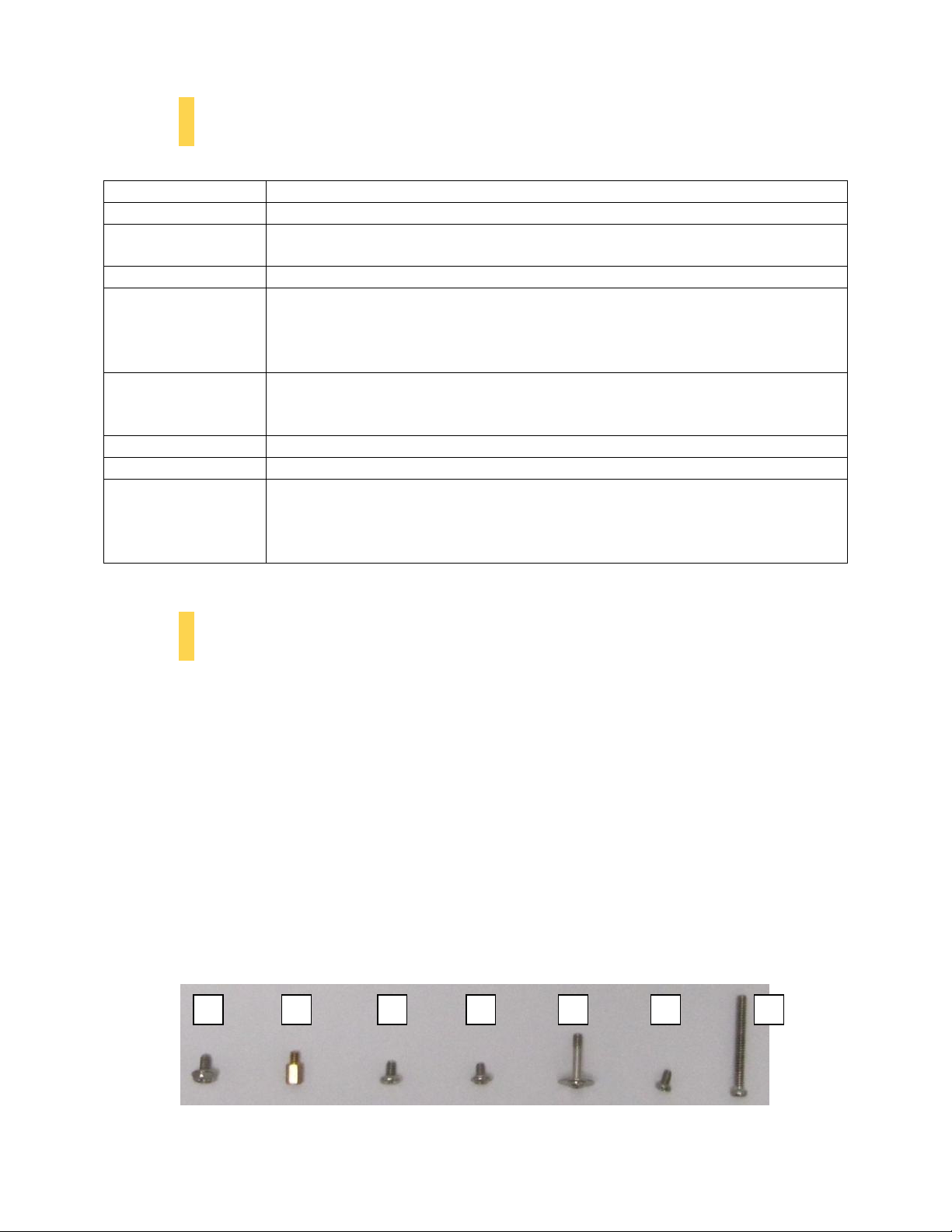
1.3 Included Screws
An inventory of all screws and intended usage and quantity is provided here:
A. Power supply screw (4)
B. Motherboard standoff (4 included, 6 preinstalled)
C. Motherboard screw (10)
D. Optional 5.25” screw / dedicated 2.5” drive bay screw (6)
E. 3.5” tray-mount screw (25)
F. 2.5” tray-mount screw (8)
G. Front fan screw (4)
H. Not pictured: zip ties for cable management (6)
6
Page 7

1.4 Before You Begin
In order to ensure that your building experience with the P280 will be a positive one, please take note of
the following:
• While working inside your P280, keep your chassis on a flat, stable surface. Make sure your build
environment is clean, well-lit, and free of dust.
• Antec chassis feature rounded edges that minimize the occurrence of hand injuries.
Nonetheless, exercise caution and control when handling chassis interiors. We strongly
recommend taking the appropriate time and care when working inside the chassis. Avoid
hurried or careless motions.
• Handle components and cards with care. Do not touch the unshielded components or contacts
on a card. Hold a card by its edges. Hold a component such as a processor by its edges, never by
its pins.
• To avoid electrostatic discharge, ground yourself periodically by touching an unpainted metal
surface (such as a connector or screw on the back of this computer) or by using a wrist
grounding strap.
• Before you connect a cable, ensure that both connectors are correctly aligned and oriented.
Bent pins can be difficult to fix and may require replacement of the entire connector.
• This manual is not designed to cover CPU, RAM, or expansion card installation. Please consult
your motherboard manual for specific mounting instructions and troubleshooting. Before
proceeding, check the manual for your CPU cooler to find out if there are steps you must take
before installing the motherboard.
• Do not sit on your chassis. Although it is constructed of heavy-duty steel and internally
reinforced, it is not designed to support the weight of an adult, and may buckle.
• Remember to use the right tools for each task. Do not use improvised screwdrivers like coins,
nails or knife blades as they may result in damage to screw threads or even injury. Do not use
your fingernails to separate edges or lift the sides of the chassis, as paint chipping or injury may
occur.
7
Page 8

Section 2
Hardware Installation
P280 User Manual
8
Page 9
2.1 Setting Up
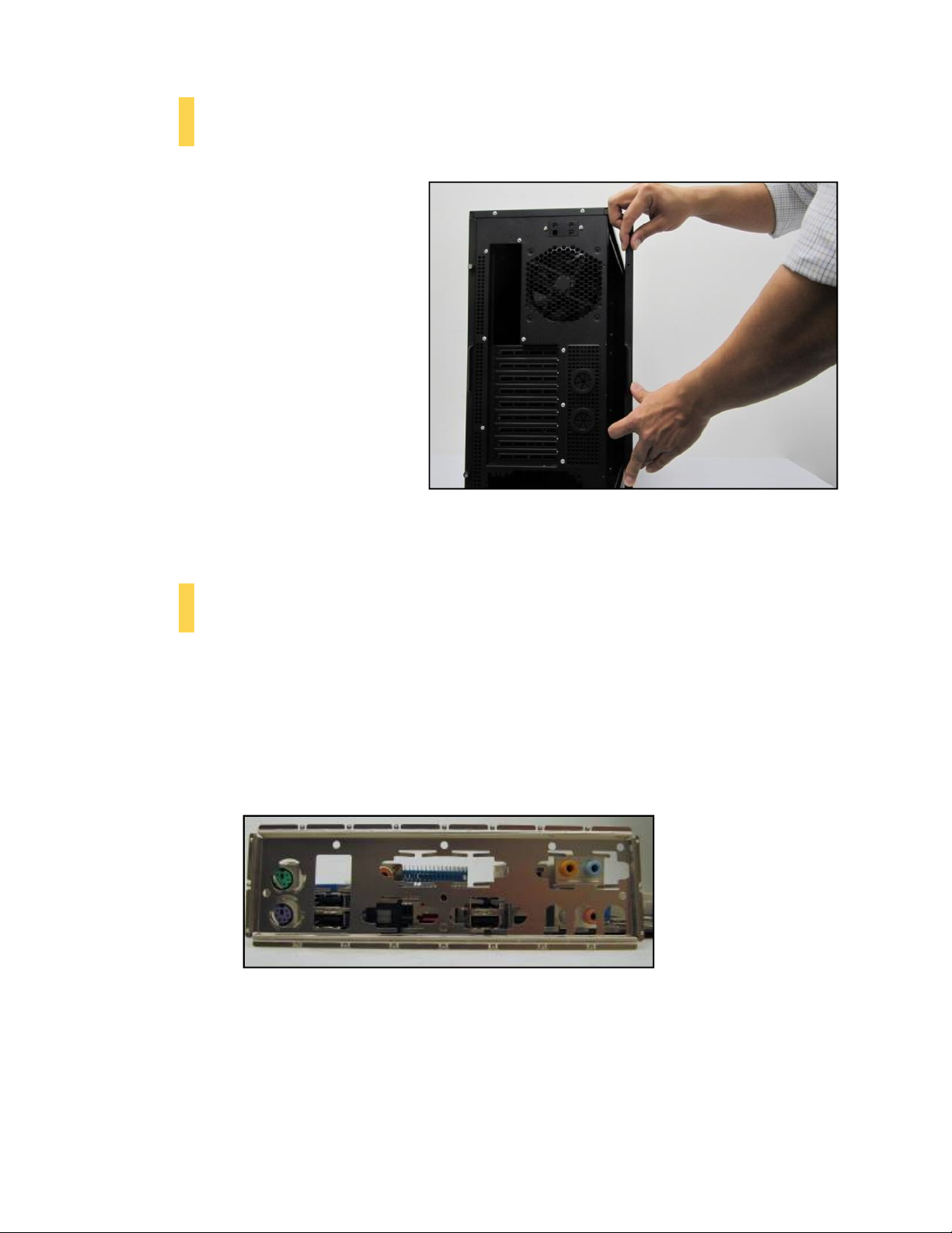
Put the case upright on a flat, stable
surface so that the rear panel (power
supply and expansion slots) is facing you.
To remove the left and right side panels,
remove these thumbscrews first.
Note: Place the panel thumbscrews aside
carefully and remember where they are.
Remove the panel by gripping the end of
the panel at the top & bottom and
swinging the panel outward. Do not pull
the panel back toward the rear of the
chassis.
Note: Do not use your fingernails to pry or lift the panels. Damage to the panels or
injury to your fingernails may result.
2.2 Motherboard Installation
Before proceeding:
Check the manual for your CPU cooler to find out if there are steps you must do before installing the
motherboard.
Make sure you have the correct I/O panel for your motherboard. If the panel provided with the chassis
isn’t suitable, please contact your motherboard manufacturer for the correct I/O panel.
Make sure you have the correct I/O panel.
9
Page 10
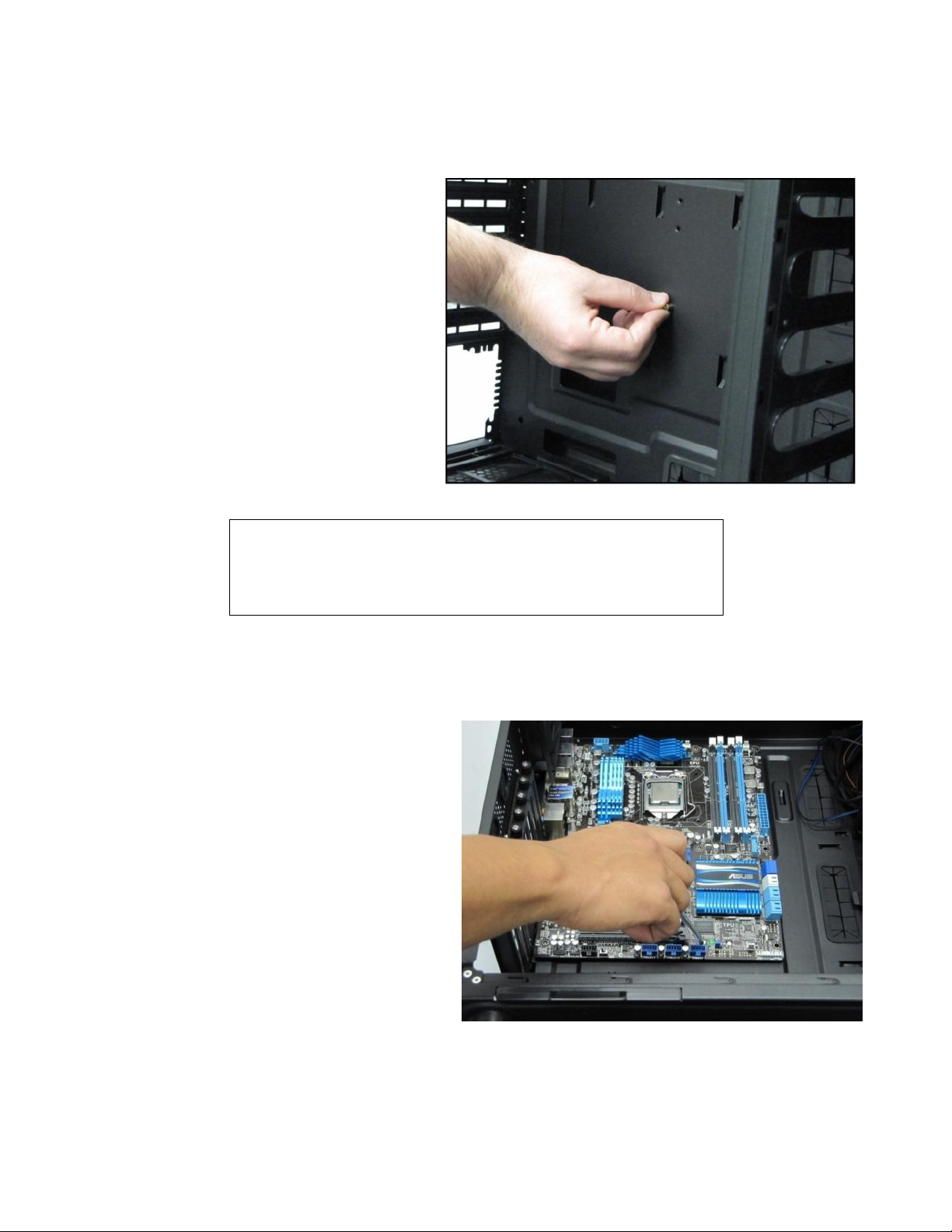
The P280 comes with six preinstalled motherboard standoffs. These are positioned for Standard ATX
Caution
motherboards but can be relocated to accommodate other form factors.
1. Align the motherboard with the
standoff holes on the motherboard
tray and remember or mark which
holes are lined up
2. Install standoffs as needed and put
the motherboard in.
Installing the motherboard standoffs.
Make sure to remove any unused motherboard standoffs. They
may come into contact with the back of the motherboard and may
electrify your chassis exterior if left connected.
3. Screw your motherboard into the standoffs with the provided motherboard mounting screws.
10
Page 11
2.3 Installing KUHLER H2O Liquid Coolers
The following instructs how to install the Antec KUHLER H2O liquid CPU cooler (620 / 920). For any other
CPU coolers, please consult your manufacturer’s installation guide.
Caution:
Check your motherboard’s CPU socket to ensure its compatibility with the KUHLER H2O. The KUHLER
H2O 620 / 920 is compatible with the following CPU sockets:
Intel® LGA 1155 / 1156 / 1366 / 2011*
AMD® AM2 / AM3 / AM2+ / AM3+ / FM1
*Your unit may not contain the LGA 2011 mounting bracket. To acquire this, please contact Antec
customer support (information listed at end of manual).
**Be sure to install the KUHLER H2O with the end of the tubes positioned at the bottom of the radiator.
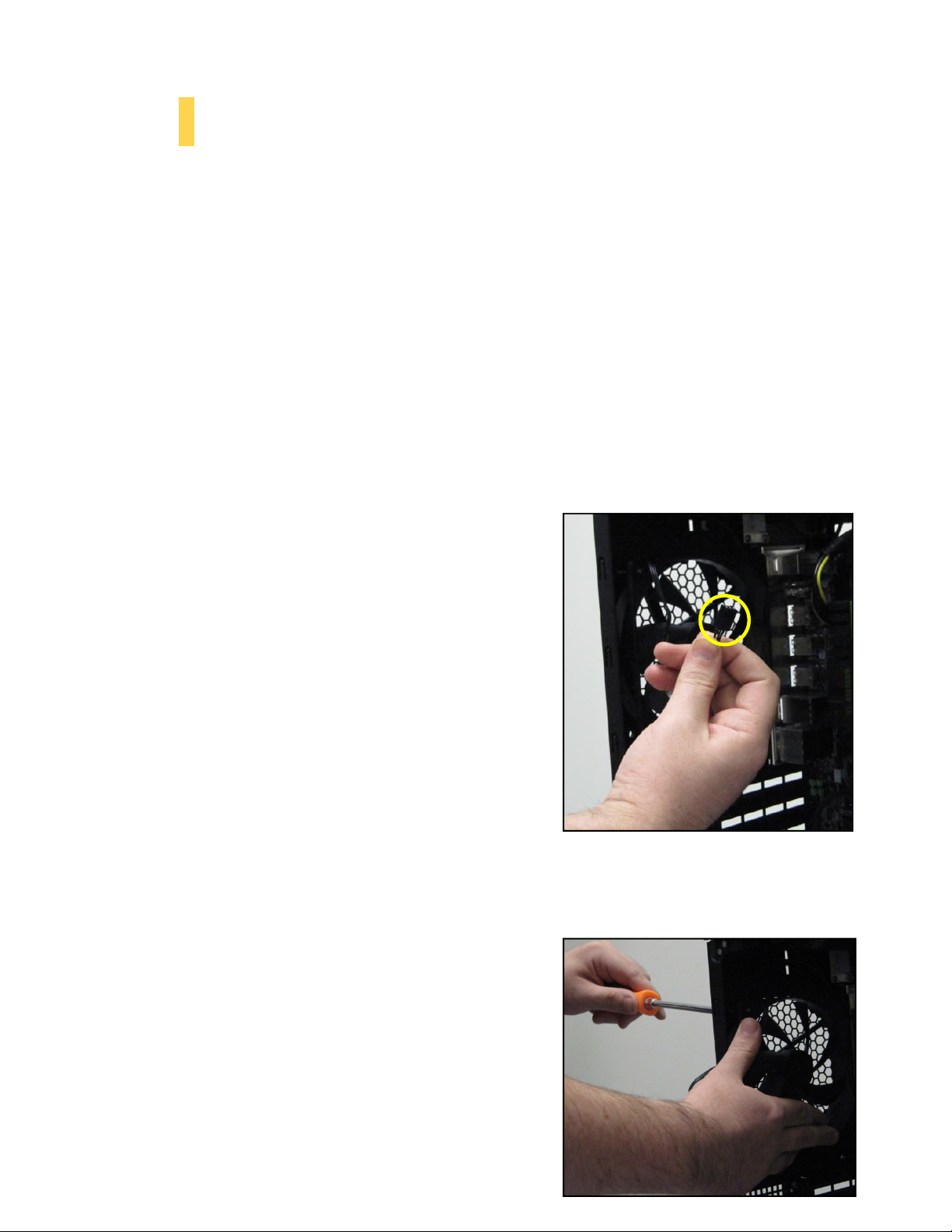
1. Remove the rear fan by first disconnecting the power
connector from the fan power hub directly above the
fan.
2. Remove the screws on the back of the chassis while
supporting the fan with your other hand.
Disconnecting the rear fan power connector
from the fan power hub.
11
Page 12
3. Preparing the KUHLER H2O backplate is specific to your CPU socket. Please refer to the KUHLER
H2O installation guide, available at
http://www.antec.com/Believe_it/product.php?id=Mjc2OCYxNw== (KUHLER H2O 620) or
http://www.antec.com/Believe_it/product.php?id=NzA0MzcwJjE3 (KUHLER H2O 920) for more
information.
4. Prepare the retention ring according to the CPU socket you’re using.
5. Complete installation according to the KUHLER H2O instructions.
2.4 Power Supply Installation
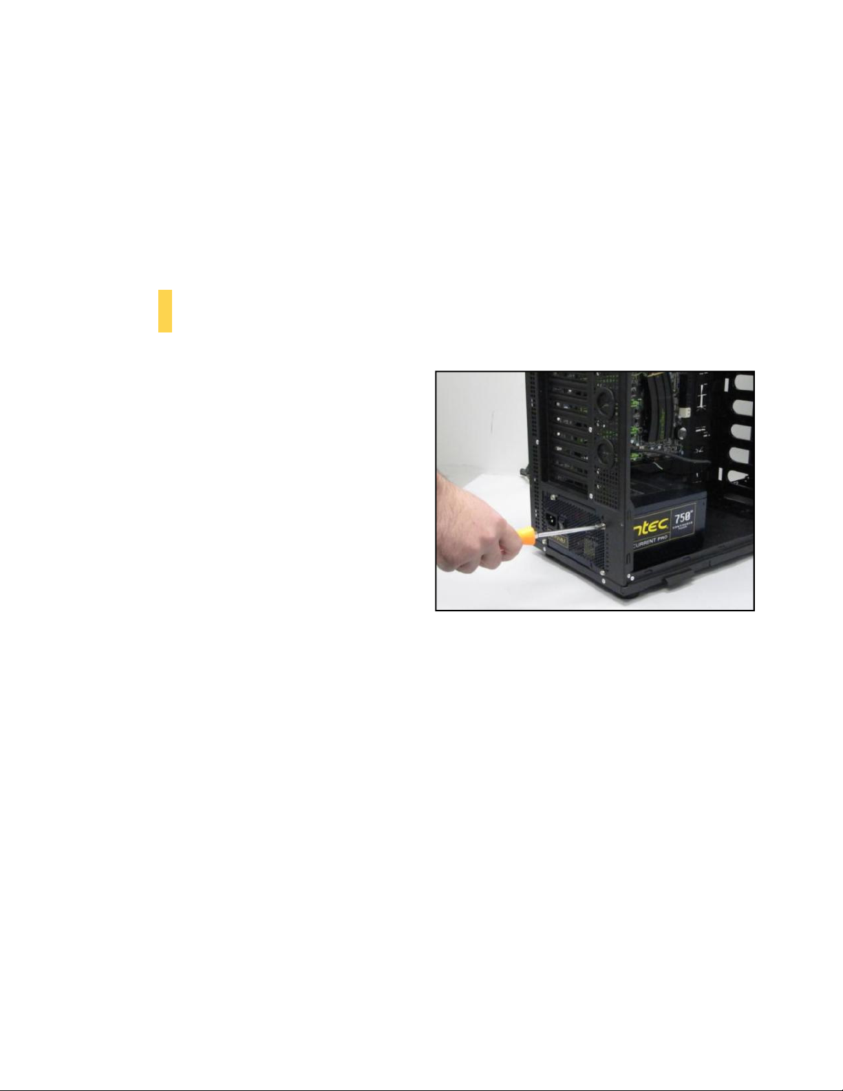
1. With the case upright, place the power
supply as illustrated in the image to the
right.
2. Push the power supply to the back of the
case and align the mounting holes.
3. Attach the power supply to the case with
the screws provided.
**See Section 4.3 for PSU filter removal instructions
12
Page 13
2.5 External 5.25” Device Installation
A
B
C
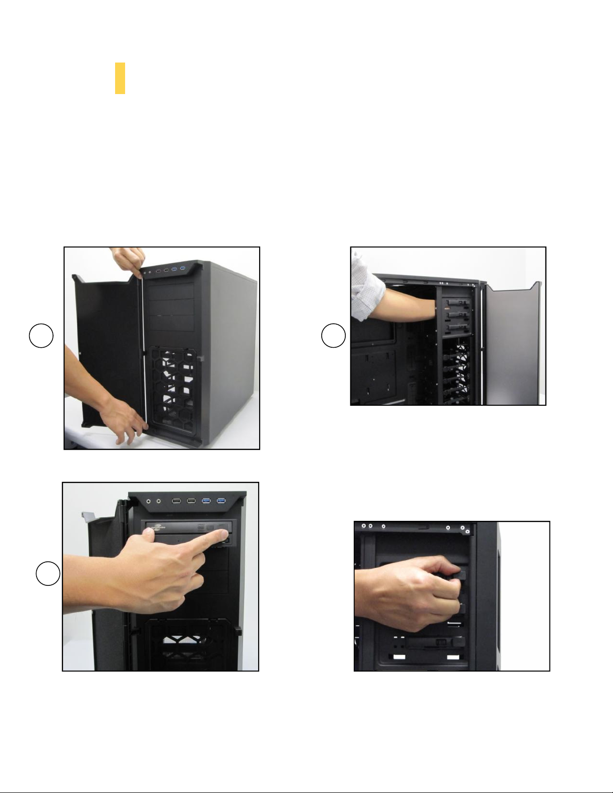
To install a 5.25” drive, you will need to remove the side panel and open the front door. For side panel
removal, please see Section 2.1.
1. With the side panel off, carefully push the drive bay cover out of the drive bay.
2. Slide your 5.25” drive through the front of the chassis until it lines up flush with the front bezel.
You will feel the drive lock into position
3. If you need more clearance on the inside of the chassis for your drive, pull the drive bay tab on
the inside of the chassis toward you and push the drive in further.
(See step 3 above if you need more clearance
for your drive.)
13
Page 14
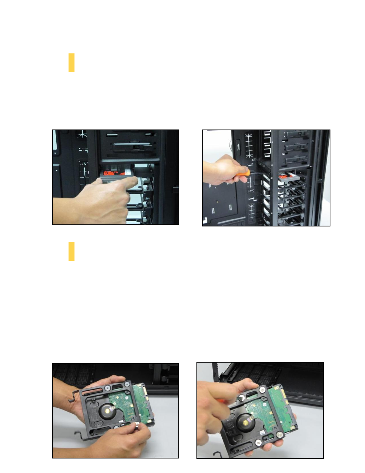
2.6 Internal 2.5” Device Installation
There are two dedicated 2.5” drive bays in the P280. To install a 2.5” drive:
1. With the side panel open, slide your 2.5” drive into the drive bay so that the drive’s holes align
with the drive bay holes.
2. Secure your drive with the 2.5” screws provided (D in Section 1.3).
2.7 Internal 3.5” / 2.5” Device Installation
The P280 has six drive bays that are compatible with both 3.5” and 2.5” drives.
To install a 3.5” drive:
1. Remove one of the drive trays by pinching the ends of the tray inward and pulling the drive tray
out.
2. Place your 3.5” drive on the tray so that the holes line up with the silicone grommets.
3. Using the 3.5” drive screws (E in Section 1.3), secure your 3.5” drive to the tray. We recommend
using your hand to find the exact threading of the drive’s holes then using a screwdriver to
completely secure your drive. Do not over-tighten the screws as this will minimize the
grommets’ ability to reduce vibration.
14
Page 15
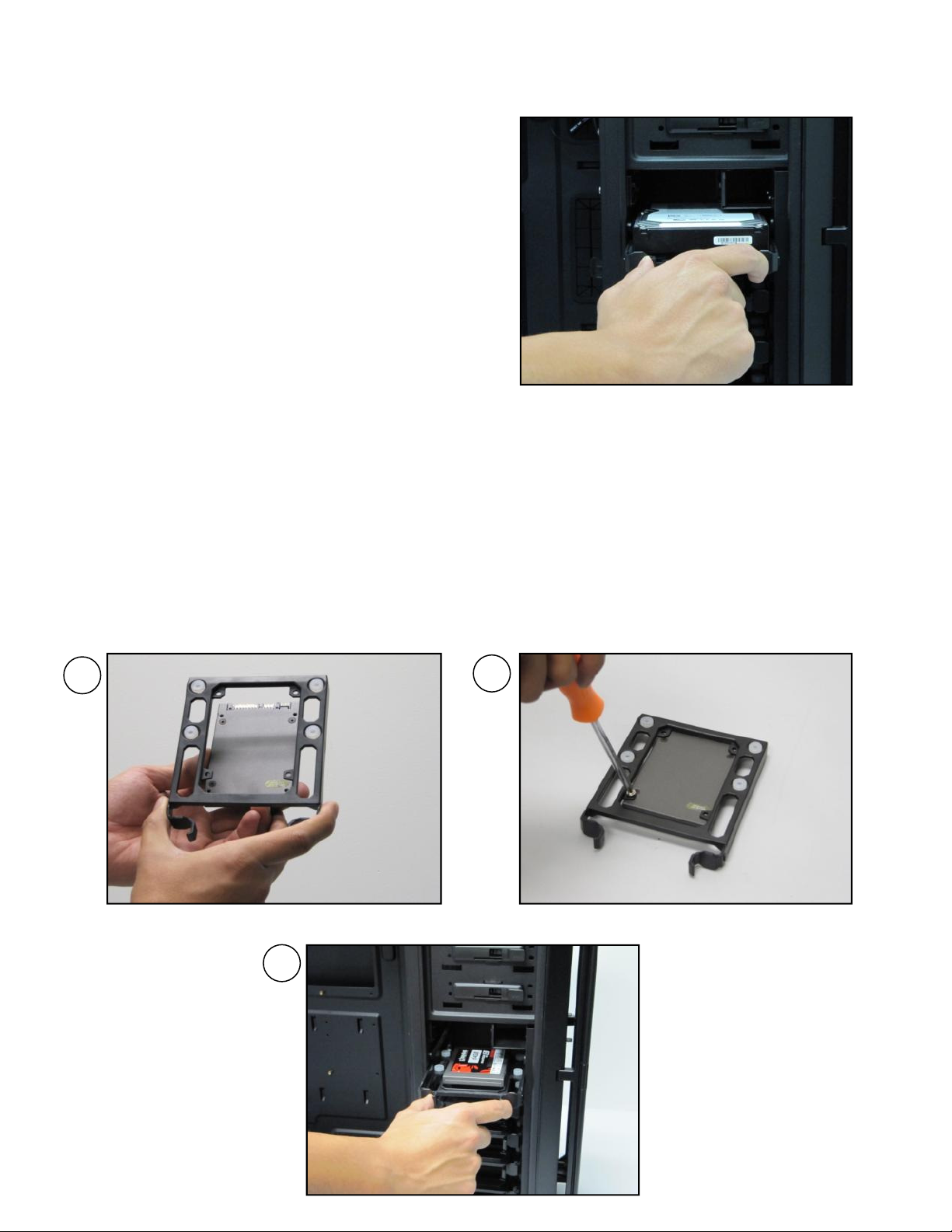
4. Now that your drive is secure to the tray, pinch
1 2
3
the ends of the tray and insert your drive into
the bay. You will hear your device click into
place.
To install a 2.5” drive:
1. Extract one of the drive trays by pinching the ends of the tray inward and pulling the drive tray
out.
2. Place your 2.5” drive on the tray so that the holes line up with the 2.5” tray holes.
3. Using the 2.5” drive screws (F in Section 1.3), secure your 3.5” drive to the tray with a
screwdriver.
4. Now that your drive is secure to the tray, pinch the ends of the tray and insert your drive into
the bay. You will hear your device click into place.
**If you need to install additional 5.25” drive bays, please remove the metal cover adjacent to
the plastic drive bay cover.
15
Page 16
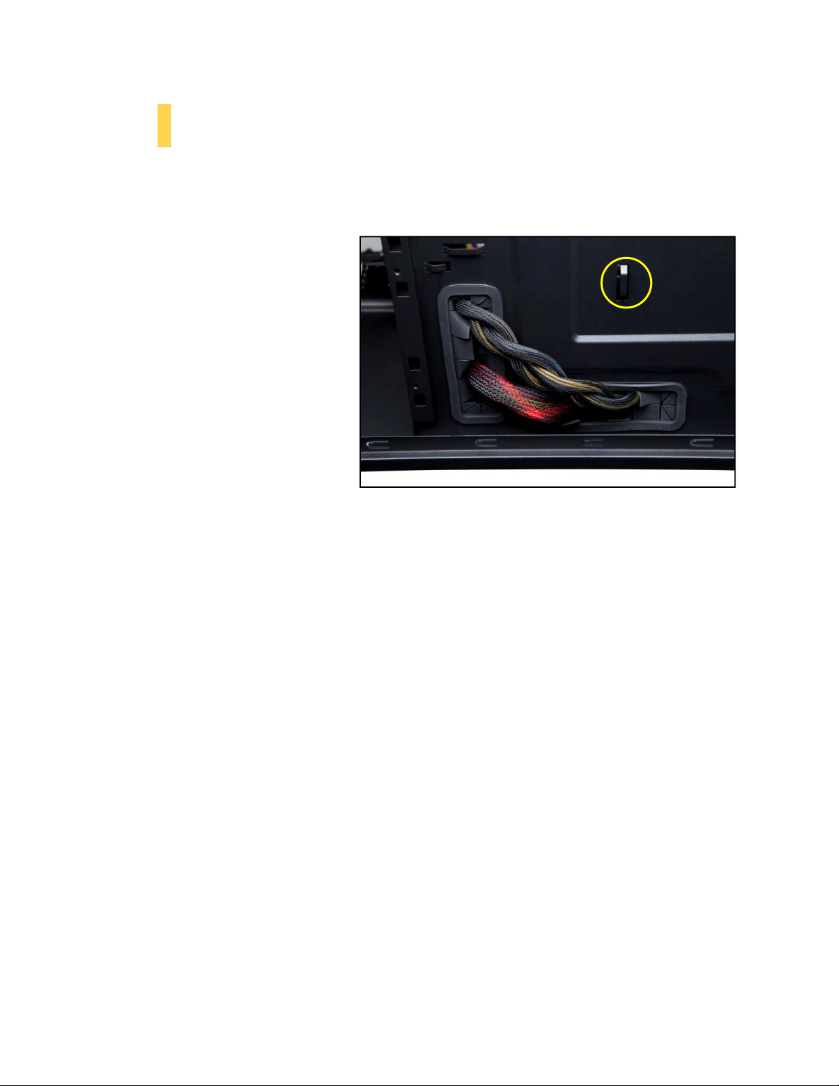
lined cable routing holes to route PSU cables.
2.8 Cable Management
There is a cable management compartment between the motherboard and right side panel, as well as
cable tiedowns located on the back of the motherboard panel. You can tuck excess cables in this
compartment or route them to the drive bays.
Choose the cables you would like to
pass through the holes behind the
motherboard tray. Pull them through
the hole toward the right side of the
case.
Use the zip ties provided to hold your
cables in place. Zip ties can be anchored
to tiedown locations located on the
back of the motherboard panel.
For cables which will be routed back to
front drives or other internal
accessories, feed the cables back
through the insertion point nearest the
destination of the cable. Connect the
cable and then pull the slack back to the
right side of the case.
For cables which will be routed directly to front drives or other internal accessories, cable tiedowns are
located along the drive cage. Bundle front drives’ or other internal accessories’ cables together and
secure them using tiedowns.
Using the grommet-
The yellow circle shows a cable tiedown
16
Page 17

Section 3
Front I/O Ports
P280 User Manual
17
Page 18
3.1 USB 2.0
1 2
9 10
Connect the front I/O panel USB cable to the USB header pin on your motherboard. Check your
motherboard user’s manual to ensure that it matches the table below:
Pin Signal
1
3
5
7
9
Names
USB
Power1
Negative
Positive
Ground1
Key
(No
Signal1
Signal1
Connection)
Pin Signal
10
Names
2
USB
Power2
4
Negative
6
Positive
8
Ground2
Empty
Signal2
Signal2
Pin
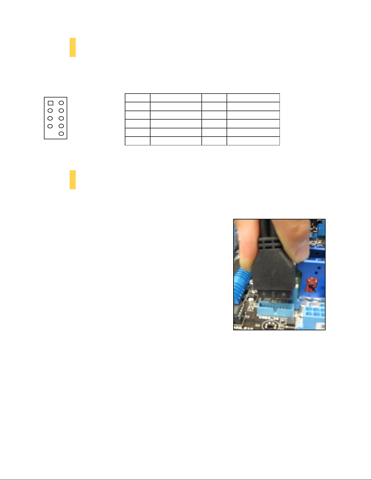
3.2 USB 3.0
The SOLO II comes with two front panel USB 3.0 ports and includes an internal motherboard connector.
To access USB 3.0 capability from the front panel:
1. Identify the USB 3.0 header on your motherboard.
2. Connect the USB 3.0 header to the motherboard port. Be
sure to align the connector in the proper orientation so
that you do not damage the pins on your motherboard.
18
Page 19
1
2
3
4
5
6
7
8
9
10
3.3 AC’97 / HD Audio Ports
There is an Intel® standard 10-pin AC’97 connector and an Intel® 10-pin HDA (High Definition Audio)
connector linked to the front panel of the chassis.
Pin
1
2
3
4
5
6
7
8
9
10
Signal Names
(HDA)
MIC2
AGND
MIC2
AVCC
FRO-R
MIC2_JD
F_IO_SEN
Key (no pin)
FRO-L
LINE2_JD
L
R
Pin
Signal Names
(AC’97)
MIC In
GND
MIC Power
N
C
Line
Out
(R)
Line
Out
(R)
N
C
Key (no pin)
Line
Out
(L)
Line
Out
(L)
You can connect either the AC’97 or the HDA connector, depending on your motherboard. Locate the
internal audio connectors from your motherboard or sound card and connect the corresponding audio
cable. Consult your motherboard or sound card manual for the pin-out positions. Even if your system
supports both standards, only use one connector.
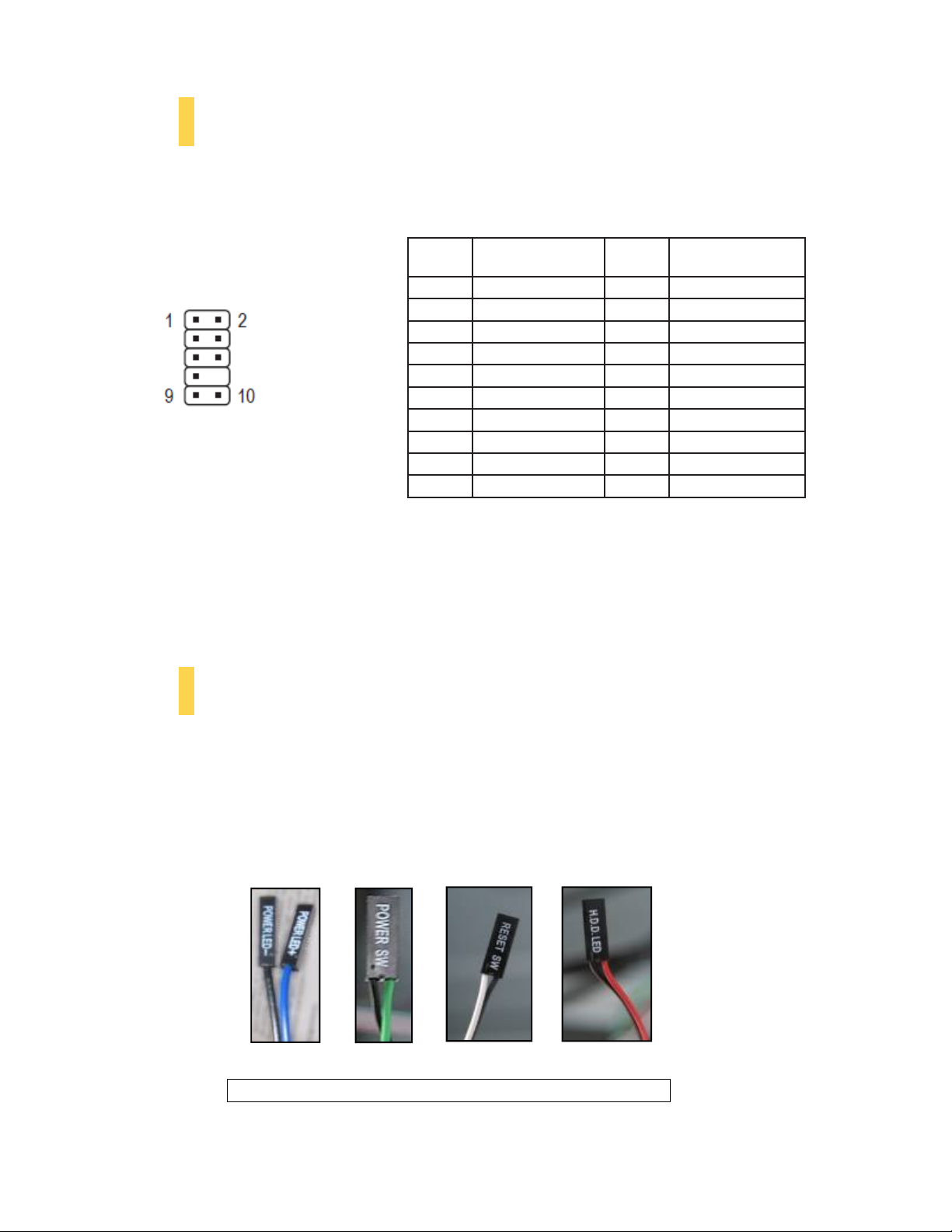
3.4 Power Switch / Reset Switch / Hard Disk Drive LED Connectors
Connected to your front panel are LED leads for power and HDD activity, as well as switch leads for the
power and reset buttons. Attach these to the corresponding connectors on your motherboard. Consult
your motherboard manual for specific pin header locations. For LEDs, colored wires are positive ( + ).
White or black wires are negative ( – ). If the LED does not light up when the system is powered on, try
reversing the connection. For more information on connecting LEDs to your motherboard, see your
motherboard user’s manual.
Note: Polarity (positive and negative) does not matter for switches.
Front panel leads
19
Page 20
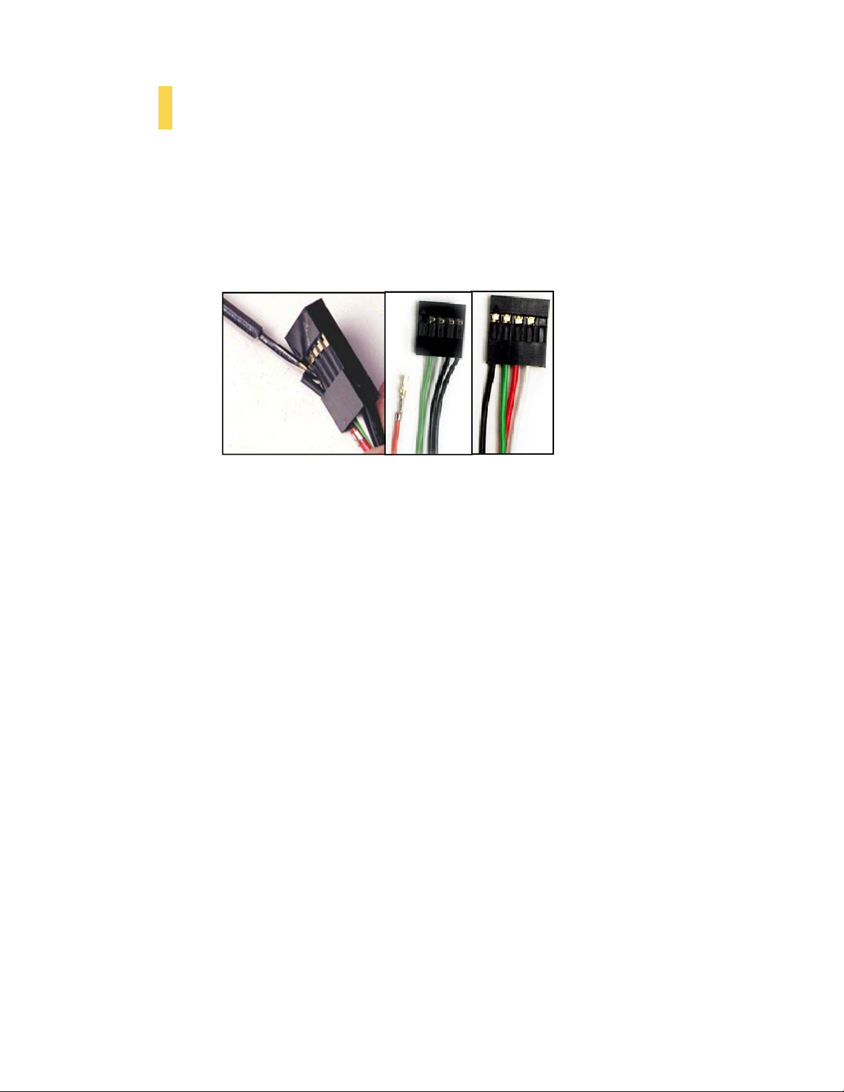
3.5 Rewiring Motherboard Header Connections
There may come a time when you need to reconfigure the pin-out of a motherboard header connector.
Examples could be for your USB header, audio input header, or some other front panel connector such
as the Power Button connector.
Before performing any work, please refer to your motherboard user’s manual or your motherboard
manufacturer's website to confirm the pin-out needed for your connector. We strongly recommend
making a notated drawing before beginning work so that you can recover if your work gets disturbed.
Determine which wires you need to remove in order to rewire your plug to match the USB pin-outs on
your motherboard (refer to your motherboard user’s manual). Working on one connector at a time, use
a very small flathead screwdriver or similar tool to lift up on the black tab located beside the gold posts
(squares). This will allow you to easily slide out the pins from the USB plug.
Working carefully so as not to damage the wires, connectors, or pins, slowly remove the pin from the
connector. Repeat these steps for each wire you need to change.
Working carefully so as not to damage the wires, connectors or pins, slowly insert the pin into the
correct slot of the connector then snap closed the black tab that was lifted in step 1. Repeat these steps
for each wire you need to change.
Front panel headers
20
Page 21

Section 4
Cooling System
P280 User Manual
21
Page 22

4.1 Included Fans
Speed
Input Current
Airflow
Static Pressure
Noise
Input Power
High
0.30A
1.43 m³ / min
1.21 mm
-
H2O
27.9 dBA 3.6W
Low
0.18A
0.84 m³ / min
0.49 mm-
H2O
16.9 dBA 2.2W
The P280 comes with two standard top 120 mm TwoCool™ fans and a standard rear 120 mm TwoCool™
fan. These fans have two-speed switches on the rear of the case that let you choose the speed best
suited to your need. The default fan speed setting is Low.
120 mm TwoCool™ fan specifications:
Size 120 x 25 mm two-speed fan
Rated Voltage 12V DC
Operating Voltage: 12V±10%
1500RPM ±10%
900RPM ±10%
(51.2CFM)
(30.1CFM)
(0.05 inch-H2O)
(0.02i nch-H2O)
4.2 Optional Fans
The P280 includes mounts for up to four more fans. These mounts are as follows:
• 2 x front intake 120 mm mounts
• 2 x internal intake 120 mm mounts
Front intake 120 mm fans
You can install these fans using 2 of the long
screws provided (G in Section 1.3). Align the
fan with the screw holes and screw in the fan
in the top-left and lower-right holes (as
pictured).
22
Page 23
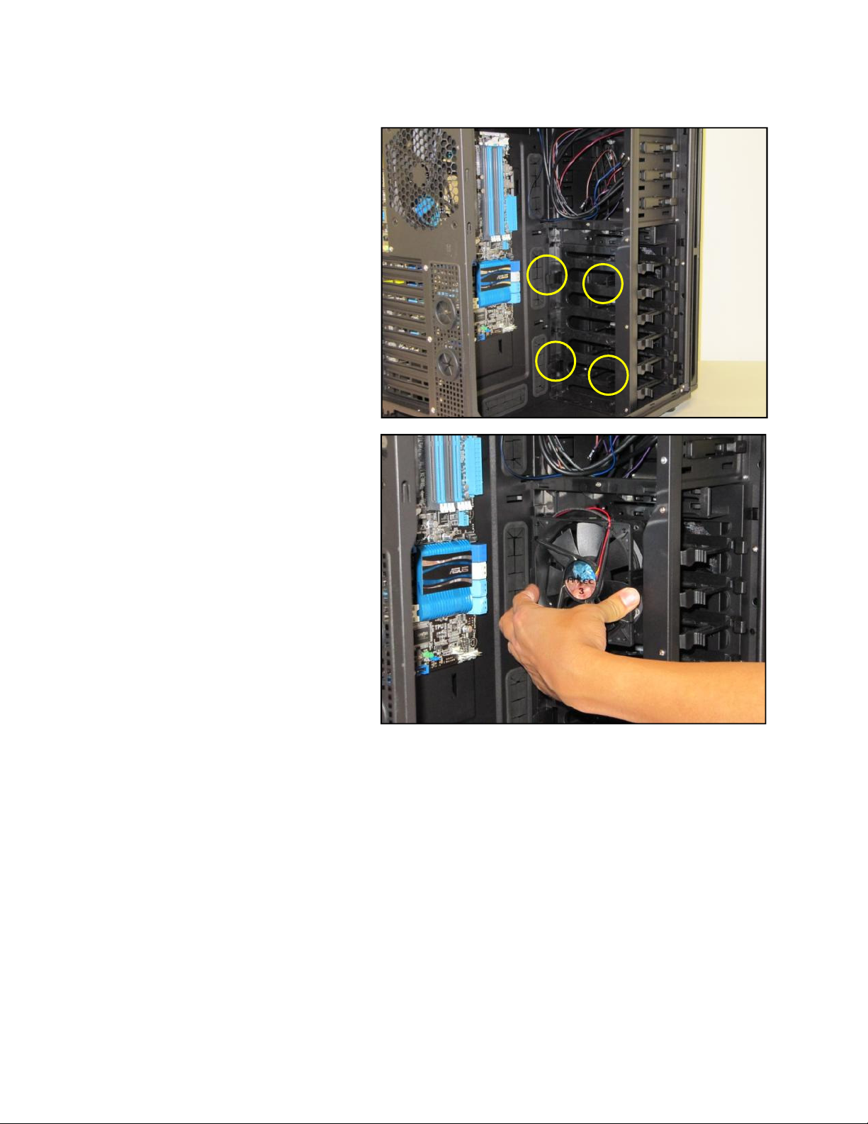
Internal intake 120 mm fans
Just outside of the 3.5” drive bay area are
two fan mounts for 120 mm internal
intake fans.
1. Align your fan with the pegs that
correspond with the fan screw
holes on the fan.
2. Push your fan into the slot until
secure. You will hear your fan
lock into place when the brackets
around the fan snap into place.
23
Page 24
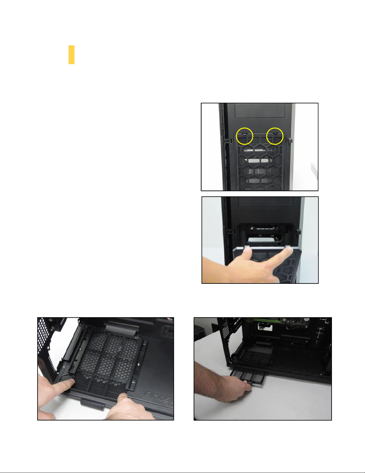
Remove the filter by pulling on the tab outside the chassis.
4.3 Air Filters
There are two filters in the P280 that can be removed and washed. One filter is the front filter and the
other is the PSU intake filter. You can access the front filter by opening the front door and pushing down
on the tabs at the top of the filter.
Note: From time to time it will be necessary to wash the
installed air filter. Not washing the air filter will result in
higher system temperatures and possible stability
problems. We recommend checking the air filter at least
once a month initially. The frequency will change
depending on system usage (users whose systems run
24/7 will likely have to check/wash more often than
those who don’t use their systems every day) and on
environmental conditions.
The P280 features a removable PSU filter that can be unlocked for maintenance and locked for
transport. To remove the PSU filter, push the ends of the filter down then pull the filter toward you
using the tab outside of the chassis. You can also lock the filter by pushing up on the tab (once the filter
is completely inside the chassis).
Push down on the ends of the filter to unlock it.
24
Page 25

Antec, Inc.
47900 Fremont Blvd.
Fremont, CA94538
tel: 510-770-1200
fax: 510-770-1288
Antec Europe B.V.
Stuttgartstraat 12
3047 AS Rotterdam
The Netherlands
tel: +49-40-226139-22
fax: +31 (0) 10 437-1752
Technical Support
US &Canada
1-800-22ANTEC
Europe
+31 (0) 10 462-2060
www.antec.com
© Copyright 2011 Antec, Inc. All rights reserved.
All trademarks are the property of their respective owners.
Reproduction in whole or in part without written permission is prohibited.
25
 Loading...