

Page 1
For Model
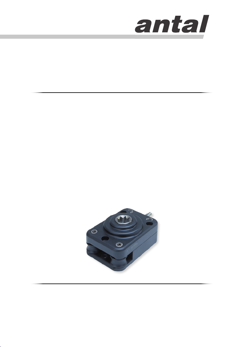
Manual Line Driver
Installation Manual
240.010
Manual Line Driver
Antal srl unipersonale, Via del Progresso, 10, 35127, Padova, Italy.
Tel. +39 049 8701265. Fax: +39 049 760906. web: www.antal.it
Technical service: [email protected]
Page 2
Installation
240.010
1. About Manual Line Driver
The control system is connected to a traveler on a closed circuit and ensures efficient control and a
clean layout.
The system uses a self tailing pulley which operates in both directions with a textile gripping system
that is efficient even if the circuit is not under strain and causes no wear in the rope.
A clutch pin sets the direction in which the traveler moves, or allows for it to be locked in the required
position.
The power ratio obtainable with a normal (250 mm) handle is 8 to 1, which is much better than a tackle
can offer; moreover, this system has a very limited size and weight.
Applications
Manual Line Driver allows to transform the rotational movement of the winch handle in a linear movement
in both directions.
Manual Line Driver originally born for the nautic market was realized for the adjusting of the mainsail,
the genoa or the spinnaker pole car. Today, Manual Line Driver is also used for other purposes outside
the nautic market, e.g. tensile structures or awnings.
Since Manual Line Driver uses a self-tailing sheave, it is advisable the use of textiles of at least
10mm diameter
Table of Models
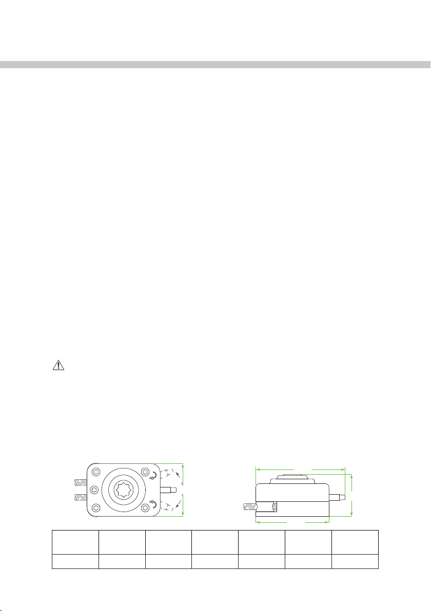
150
90
122
Model LINE
240.010 10 8:1 0.44 36 2000 3 x 8 mm
mm
POWER Weight
kg
For Boats
Up To (ft)
SWL
kg
58
Screws
not included
Page 3
Installation
240.010
2. Installation
To install Manual Line Driver, you will need: drill, sealant, 3 x Ø8 mm hex socket cap screws (screws
not included).
Installation
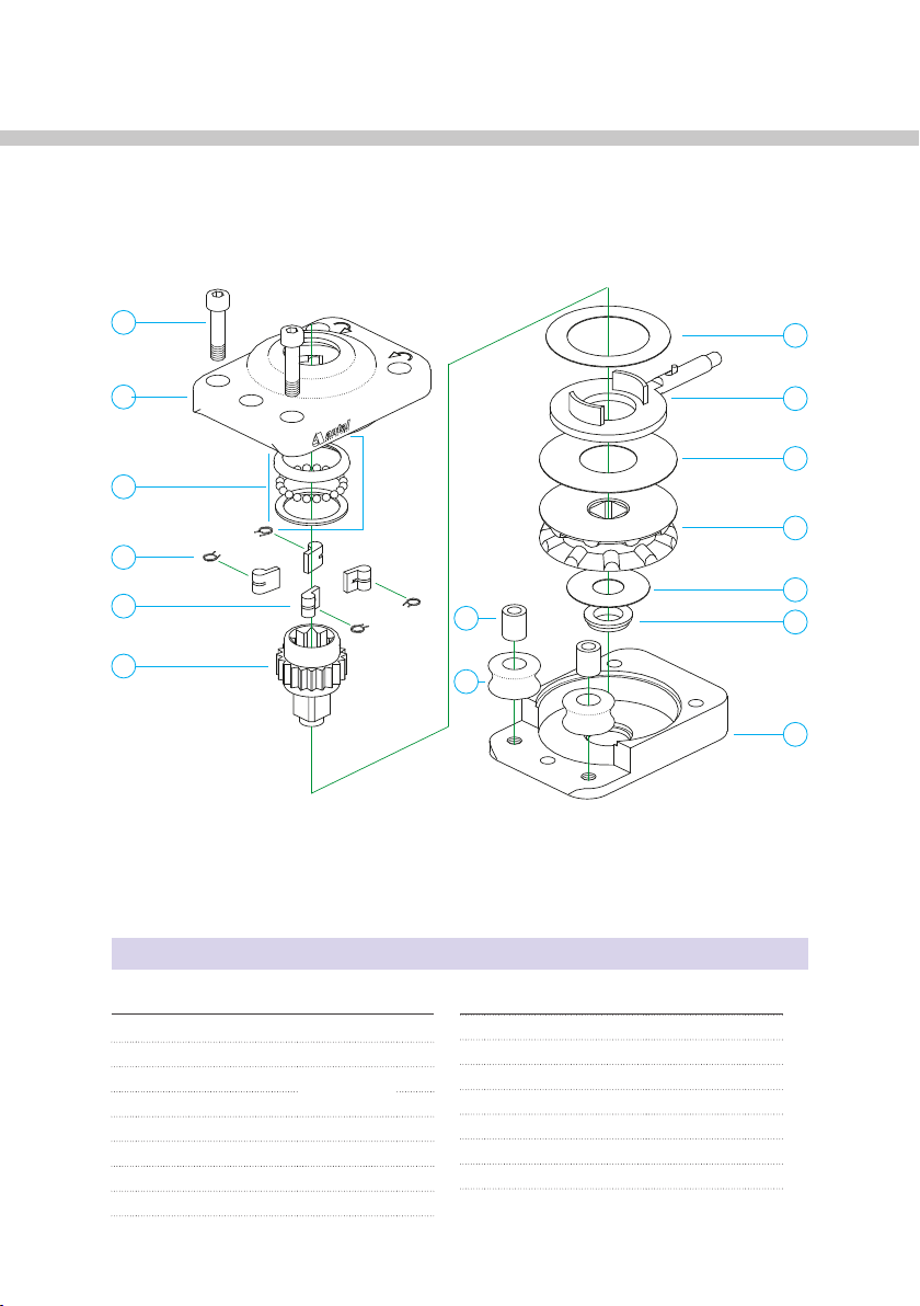
Refer to the exploded view drawing to identify the parts of Manual Line Driver
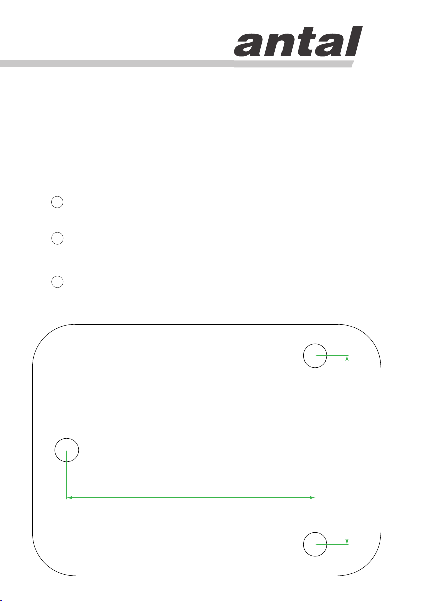
Use the base (16) as template to mark the anchoring holes on the deck, alternatively refer to
1
the below real size drilling template. Thus drill the deck.
Cut screws to required length. Use Loctite 222 or 243 on fasteners’ thread to avoid unscrewing.
2
Use sealant around all the anchoring holes on the deck under the Manual Line Driver base.
Thus tighten all anchoring screws and nuts.
Insert the line when Manual Line Driver is closed and installed. In case the line is spliced or in
3
case it does no go through, it is necessary to open Manual Line Driver. Refer to the exploded
view drawing to proceed to opening Manual Line Driver.
66
87
Page 4
Exploded View
ty
ty
10
MIDDLE WASHER
FIBRE
1
01
02
03
04
05
06
14
15
08
09
10
11
12
13
16
240.010
N° DESCRIPTION MAT ERI AL Q.
01 SCREW S.STEEL 2
02 UPPER BOX ALUMINIUM 1
03 BALL BEARING
(24 BALLS + 2 RIN GS)
04 PAWL SPRI NG S.STEEL 4
05 PAW L BRONZE 4
06 MAIN SHAF T S.STEEL 1
08 UPPER WASHER FIBRE 1
09 CONTROL LEVER 1
rev. 20-feb-2015
N° DESCRIPTION MAT ERI AL Q.
11 MAIN SH EAVE ALUMINIUM 1
12 LOWER WASHER FIBRE 1
1
13 LOWER BUSH STEEL 1
14 ROLLER BUSH S.STEEL 2
15 ROLLER PLASTIC 2
16 LOWER BOX ALUMINIUM 1
 Loading...