

Page 1
Always be your solar support
www.antai
solar.com
ANTAI Installation Manual
Flat Roof Solution
(Solar mounting system)
Page 2

CONTENTS
General Introduction·································································································································· 2
Technical Specification ······························································································································ 3
Safety and Installer Responsibilities ······································································ 4
Components List ····································································································· 5
Before Installing ············································································································································ 6
Receipt of Goods ··································································································· 6
Tools Required for Installation ········································································································································ 6
Installation Planning ··································································································································· 7
Determining Wind Terrain Category ········································································· 7
Determining Wind Region ································································································· 8
Planning the Module Area ·························································································· 9
Designing Your Tilt System ···································································································· 10
Determine the Height of The Installation Site ·························································· 11
Verify Acceptable Rail End Overhang ····································································································································· 11
Verify Acceptable Rail End Overhang ····································································································································· 11
Determine Roof Slope ···························································································································· 11
Determine the Maximum Rail Support Spacing ························································ 11
Installation Instruction ························································································································· 12
Warranty ························································································································································ 16
Maintenance and Cleaning ···················································································································· 19
References····················································································································································· 19
Contact Details ············································································································································ 19
Page 3
GENERAL INTRODUCTION
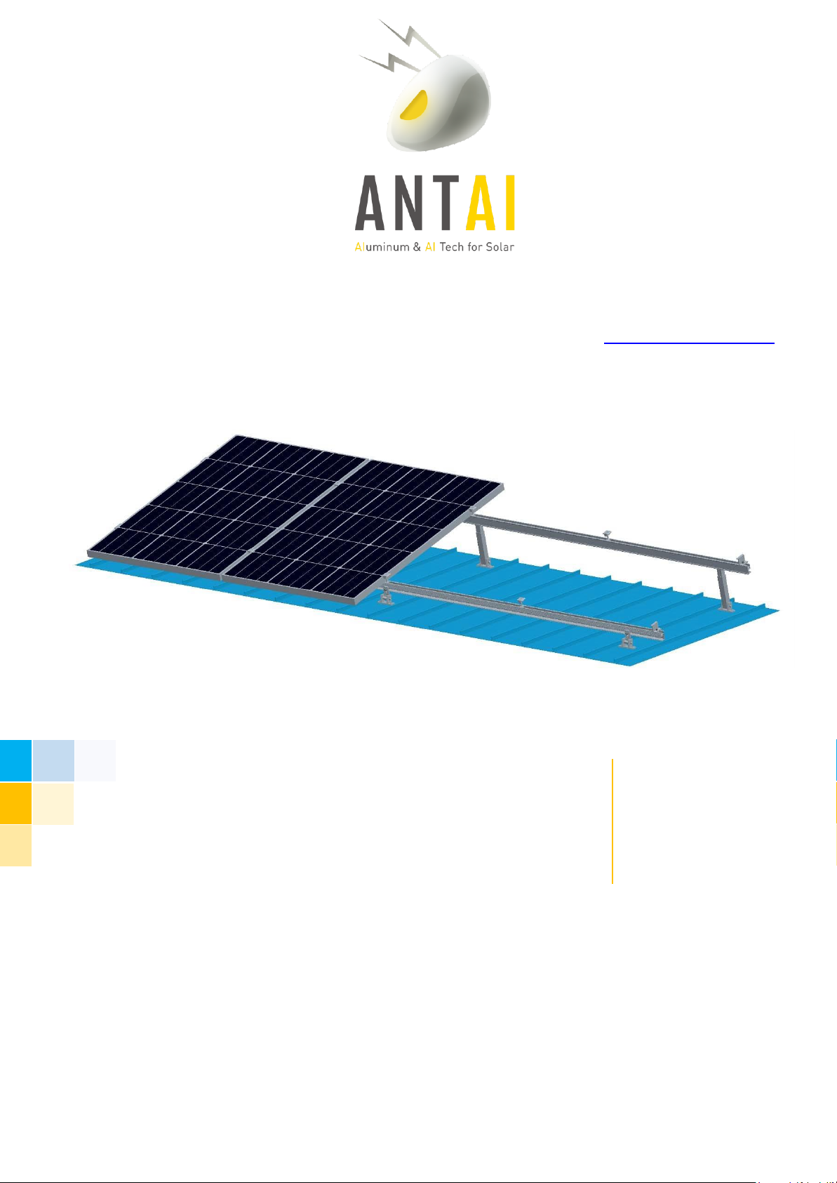
ANTAISOLAR/ANTAI flat roof adjustable tilt mounting system has been developed as a universal PV
module mounting system for flat roof or open space ground installation. 10-15, 15-30, 30-60
adjustable degree optional. The innovative and the high degree of pre-assembly eliminate the
need for onsite cutting, welding and enables quick and easy field PV module installation.
Rail II
Easy to be installed
ANTAISOLAR/ANTAI features series of highly engineered new innovative product, designed with
experienced engineers to the speed of installation.
ANTAISOLAR/ANTAI pitched roof solar mounting system is backed by a 10-year warranty and is
compliant with AS/NZS1170.2.2011(R2016)
Benefits of ANTAISOLAR/ANTAI Flat Roof Mounting System
● Easy Installation
● Diversified Application
● High Accuracy
● Choice Quality
● Engineered to highest standards
● Maximum Lifespan
● Guaranteed durability
Page 4

TECHNICAL SPECIFICATIONS
Applications
⚫ Commercial and residential buildings
⚫ Marine applications and remote areas
Features
⚫ Anodized 6005-T6 aluminum extrusion
⚫ Innovated designed of the Tilt-in modules, which can be pre-assembly with the clamp, make
the installation easy and quick.
⚫ Suitable for difference conditions and the most solar panels at present market.
⚫ Significantly higher strength-to-weight ratio than other framing products, providing improved
efficiency due to greater frame spans, inherent corrosion resistance resulting in low ongoing
maintenance and an extended product life.
⚫ Complies with Australian/New Zealand Standard on Wind Actions, AS/NZS1170.2.2011/Amdt
3:2013
⚫ 10 years limited warranty backed up by parent company ANTAISOLAR/ANTAI Aluminum
Material
Material
Tensile strength
Tensile
Yield
6005 T6 aluminum
extruded
≥260Mpa
≥225Mpa
Stainless steel 304
625.55Mpa
263.8Mpa
Stainless steel A2-70
700MPa
450Mpa
Installation condition
Roof slope
Up to 60°
Building height
Up to 20m
Mounting structure
Timber/ steel
Roof types
Open Area/Trapezoidal metal sheet/Klip-
Lok® roof
System angle
Flush with roof
Note: If the condition is beyond the table list, please contact us to confirm
Page 5

Handling and Installing ANTAISOLAR/ANTAI
It is critically important that safety practices are observed when installing
⚫ Do not throw or roughly handle any ANTAISOLAR/ANTAI components.
⚫ Do not bring ANTAISOLAR/ANTAI solar system into contact with sharp or heavy objects.
⚫ Do not modify ANTAISOLAR/ANTAI solar components in any way. The exchange of bolts, drilling of
holes, bending or any other physical changes not described in standard installation procedure will void
the warranty.
⚫ It is the installer’s responsibility to verify the integrity of the structure to which ANTAISOLAR/ANTAI
solar components is fixed. Roofs or structures with rotten/rusted bearers, undersized bearers,
excessively spaced bearers, or any other unsuitable substructure cannot be used with
ANTAISOLAR/ANTAI solar components, and installation on such structures will void the warranty, and
could result in death or serious injury.
Wind and Climate Design
AS/NZS1170.2.2011 provides guidance on determining the wind pressures applicable to your
ANTAISOLAR/ANTAI solar system install site, taking into account roof shape and geographic location.
Sufficient guidance is given in this document, but you may wish to procure a copy of these standards if
your company installs Australia/New Zealand wide.
⚫ REMEMBER average wind speeds are higher for structures mounted closer to the roof perimeter zone
(edge). Refer to ‘Fixing within Roof Installation Zone’ for more information)
⚫ Make sure your installation complies with local and national building codes. Take into account relevant
design parameters (wind speed, exposure and topographic factor) when determining the loading for
the installation.
⚫ If alternative fasteners are used to ix the framing to the roof (assuming supplied fasteners are
unsuitable for any reason), all screw fasteners must conform to corrosion resistance Class 4
Australian Standard AS3566 and be of equal or greater strength to those supplied with your
ANTAISOLAR/ANTAI solar system order.
CAUTION: INSTALLATION OF THIS PRODUCT IS TO BE PERFORMED ONLY BY PROFESSIONALLY TRAINED
INSTALLERS. ANY ATTEMPT BY AN UNQUALIFIED PERSON TO INSTALL THIS PRODUCT COULD RESULT IN
DEATH OR SERIOUS INJURY.
Page 6
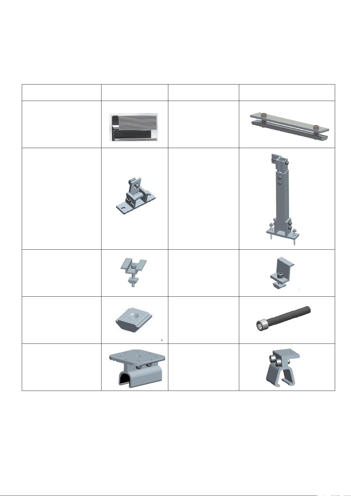
Overview of system components
Part name
Picture
Part name
Picture
Rail VI TYN-355
Rail Splice
Front foot
Adjustable rear leg
220mm(10-15deg)
350mm(15-30deg)
600mm(30-60deg)
Inter Clamp
(with T-module)
End Clamp
(with T-module)
T-module
Hexagon socket bolt
M8*30/45/50/55/60
Kliplok 700 Clamp
Kliplok 406 Clamp
Note: The quantity of requested components depends on the system you ordered.
Page 7
BEFORE INSTALLING
Receipt of goods
Check that the ANTAISOLAR/ANTAI solar equipment is undamaged and that the order is complete.
Check for correct quantities of the items.
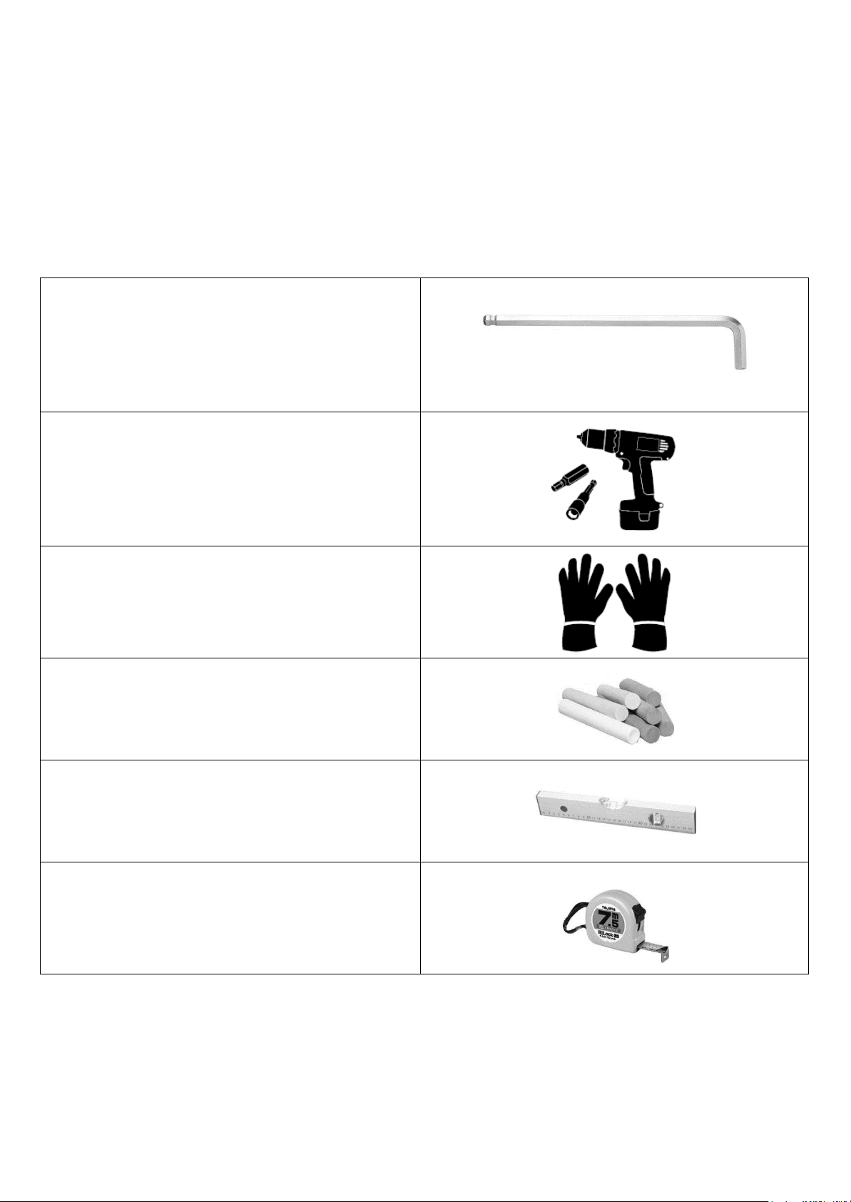
Tools required for installation
6 mm Allen key or hexagonal driver bit.
If using a 6mm driver bit, make sure the cordless
power tool used for the driving has a hand-tight
clutch setting a fine (soft) impact drive to prevent
damage to the fragile glass panels and threads on
the structure.
Cordless drill.
Drill or impact driver for driving roof material
fixings
Gloves.
Protect the hazard of the sharp corners.
Cord or color pen.
Mark the installation position.
Spirit level
Measuring tape
Page 8
INSTALLATION PLANNING
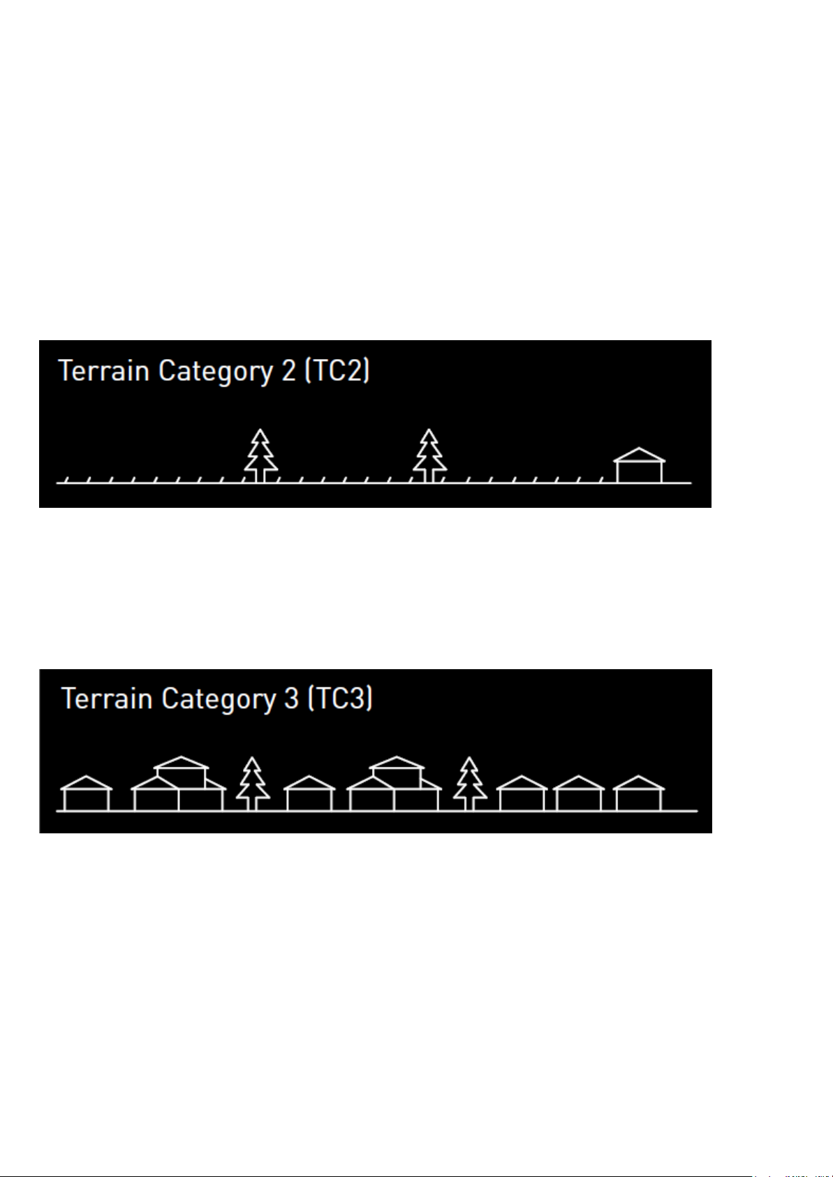
DETERMINING WIND TERRAIN CATEGORY
Terrain Category 2
Open terrain, including grassland with well scattered obstructions having heights generally from
1.5 meters to 5 meters. Examples include farmland or cleared sub-divisions with isolated trees
and uncut grass.
Terrain Category 3
Terrain with numerous closely spaced obstructions having heights generally from 3 meters to 10
meters. Examples include typical suburban housing or light industrial areas.
Page 9
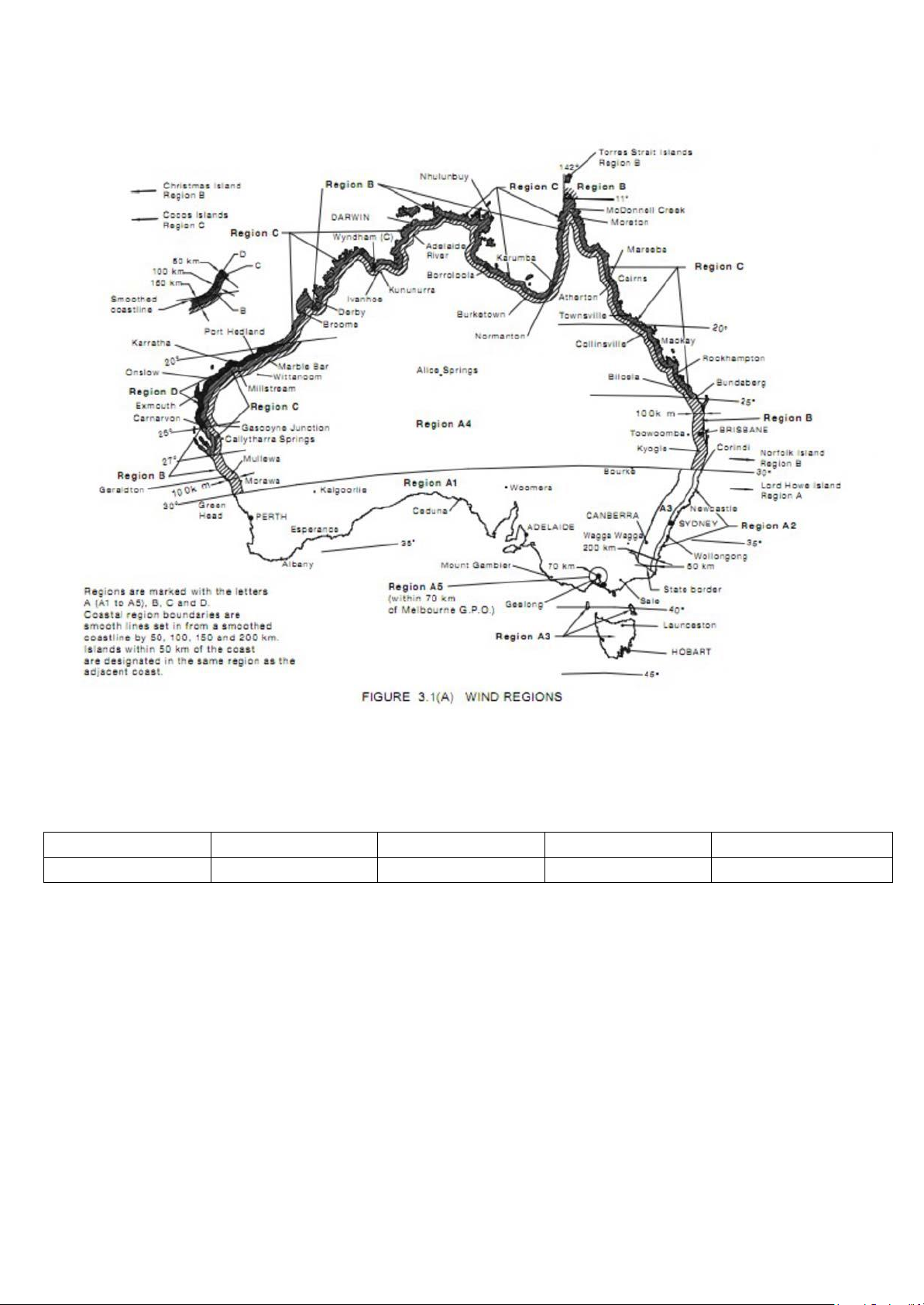
DETERMINING WIND REGION
Figure: National wind map (in accordance with AS/NZS 1170.2:2011/Amdt 3:2012)
Wind regions are pre-defined for all of Australia by Australian Standard AS/NZS 1170. The Wind Region
has nothing to do with surrounding topography or buildings.
Wind Zone
A B C
D
Wind Speed (m/s)
43
52
64
79.2
Included towns:
Region A:
Callytharra Springs, Gascoyne Junction, Green Head, Kununurra, Lord Howe, Island, Morawa,
Toowoomba, Wittanoom, Bourke
Region B:
Adelaide River, Atherton,Biloela, Brisbane,Christmas Island, Collinsville, Corindi, Geraldton, Ivanhoe,
Kyogle, Marble Bar, Mullewa, Norfolk Island, Torres Strait Islands, Wyndham
Region C:
Borroloola, Broome, Bundaberg, Burketown, Cairns, Cocos Islands, Darwin, Derby, Karumba, Mackay,
Mareeba, Millstream, Moreton, Nhulunbuy, Normanton, Rockhampton, Townsville
Region D:
Carnarvon, Exmouth, Karratha, Onslow, Port Hedland
Page 10
PLANNING THE MODULE AREA
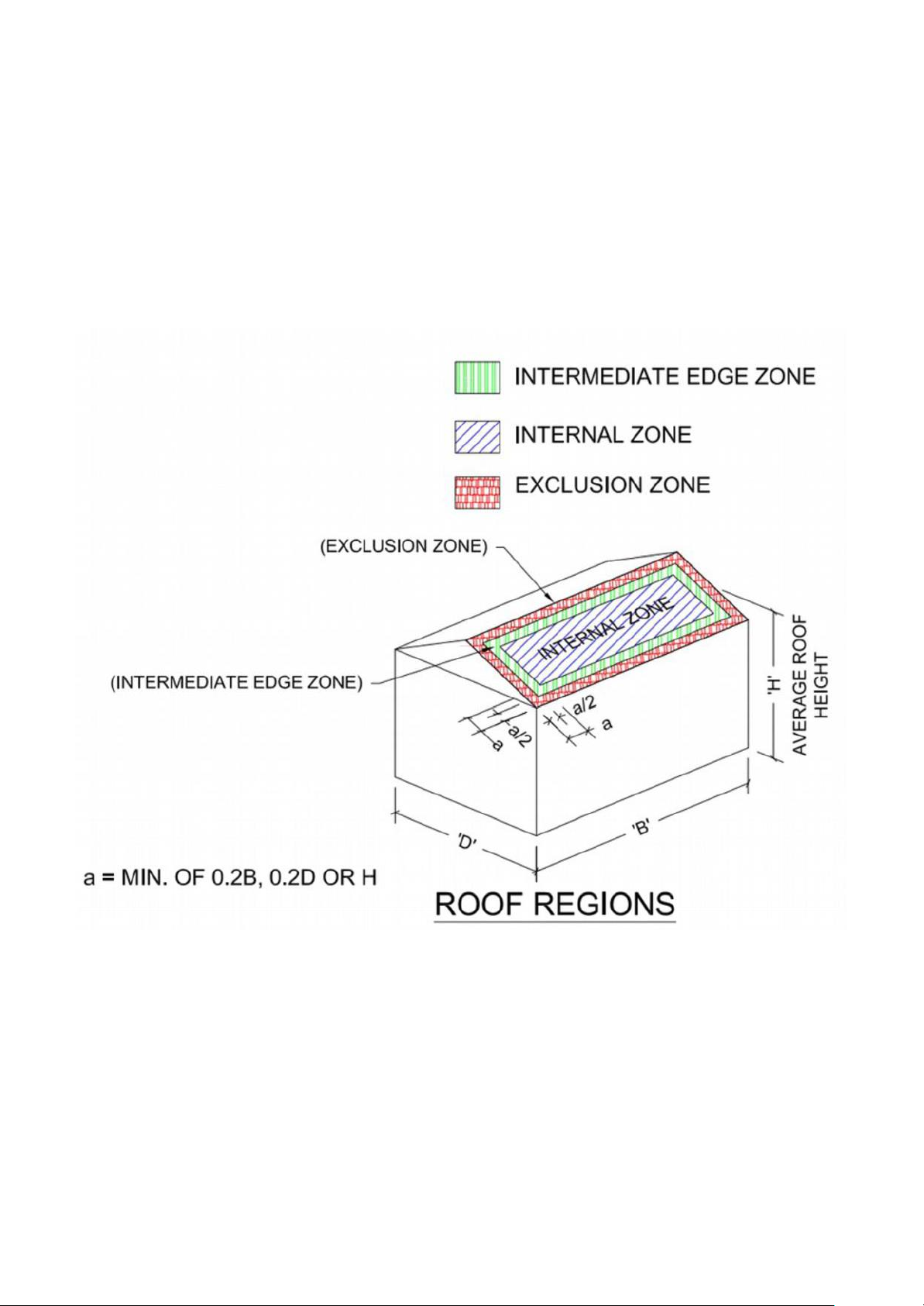
Solar panels can be installed anywhere on the roof, as long as sufficient fixings are used. Higher wind
speeds are encountered at the edges of roofs and therefore more fixings are required in these areas.
For a tilted array, a roof can be divided into three zones, the internal zone, intermediate zone and the
edge zone. The width of these outer zones can be determined based on the length, width and average
height of the building. If fixings are located in the intermediate, edge or end zones, then the maximum
spacing to the next fixing must be reduced, as per the table in the certifications.
Determining the width of the edge and intermediate zones, ‘A’ the width of the edge and intermediate
zones, ‘A’, is determined by calculating each of the following values, and then using the smallest:
0.2 x B, 0.2 x D/H
Page 11
DESIGNING YOUR TILT SYSTEM
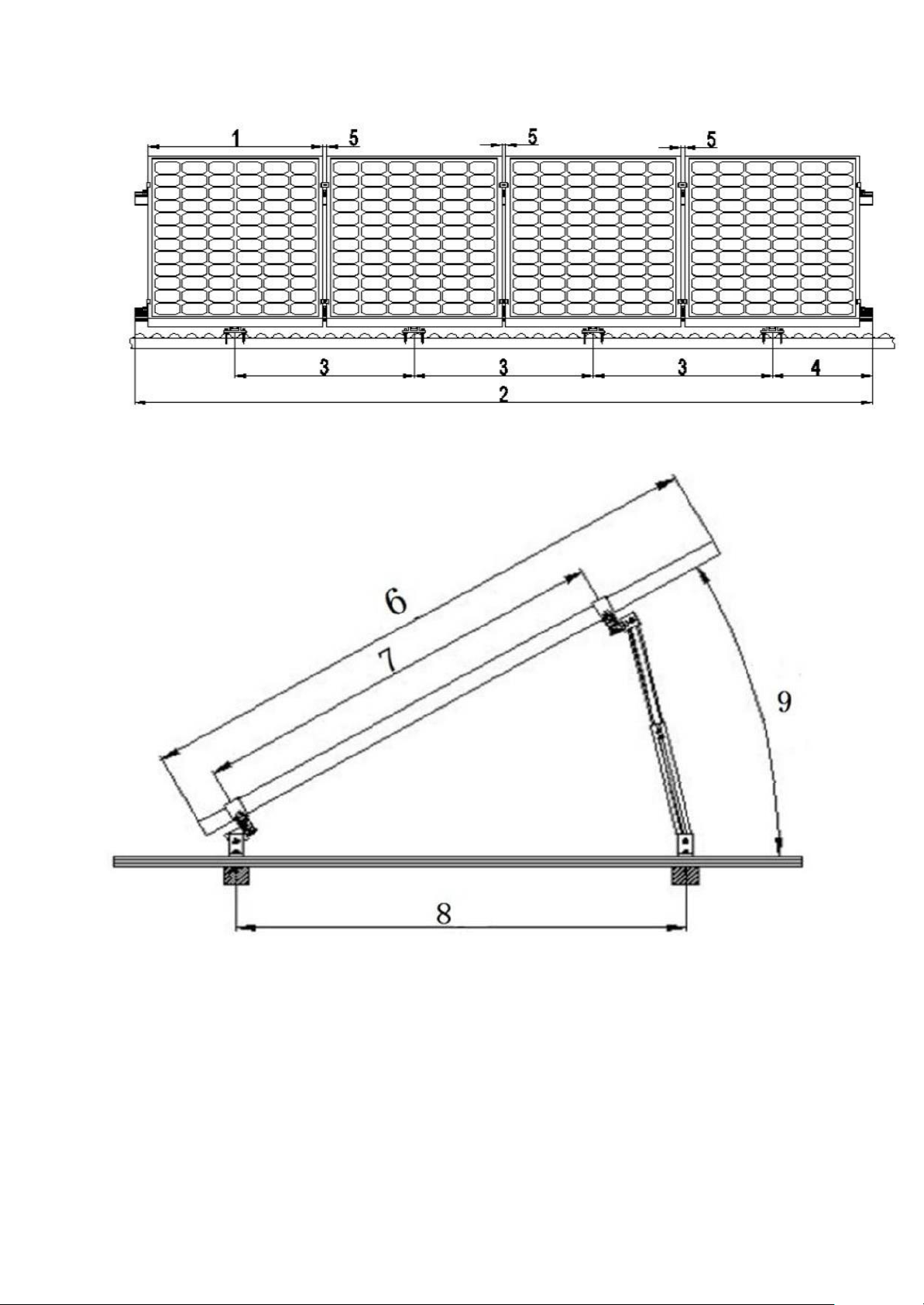
1. Width of the module
2. Length of ANTAISOLAR/ANTAI solar Rail: number of modules horizontally x (width of the module + 17 mm)
+70 mm
3. Distance between roof connections horizontally: Depending on the distance between rafters and on the
static requirement.
4. Cantilever Length: less than half of dimension 3
5. Distance between modules: 17 mm
6. Length of the module
7. Length of support: similar with the dimension 8
8. Front and Rear Space: 1200~1400mm
9. Adjustable degree: 10-15deg / 15-30deg / 30-60deg
Page 12

DETERMINE THE HEIGHT OF THE INSTALLATION SITE
This document provides sufficient information for ANTAISOLAR/ANTAI solar system installation
height less than 20 meters. If your installation site is more than 20 meters in height, please contact
ANTAISOLAR/ANTAI to obtain engineering data to support your installation.
VERIFY ACCEPTABLE RAIL END OVERHANG
Rail end overhang must equal 50 percent or less of foot spacing. Thus, if foot spacing is 1200mm, the
Rail end over hang can be up to 600mm. In this case, two feet can support a rail of as much as 2400mm
(1200mm between the feet and 600mm of overhang at each end).
DETERMINE ROOF SLOPE
ANTAISOLAR/ANTAI solar mounting system can be used for roof slope up to 60 degrees. This
document provides sufficient information for below 30 degrees, please contact ANTAISOLAR/ANTAI
solar for between 30 and 60 degrees.
DETERMINE THE MAXIMUM RAIL SUPPORT SPACING
Please use the table in engineering certificate to determine the ANTAISOLAR/ANTAI support spacing for
installations.
Page 13
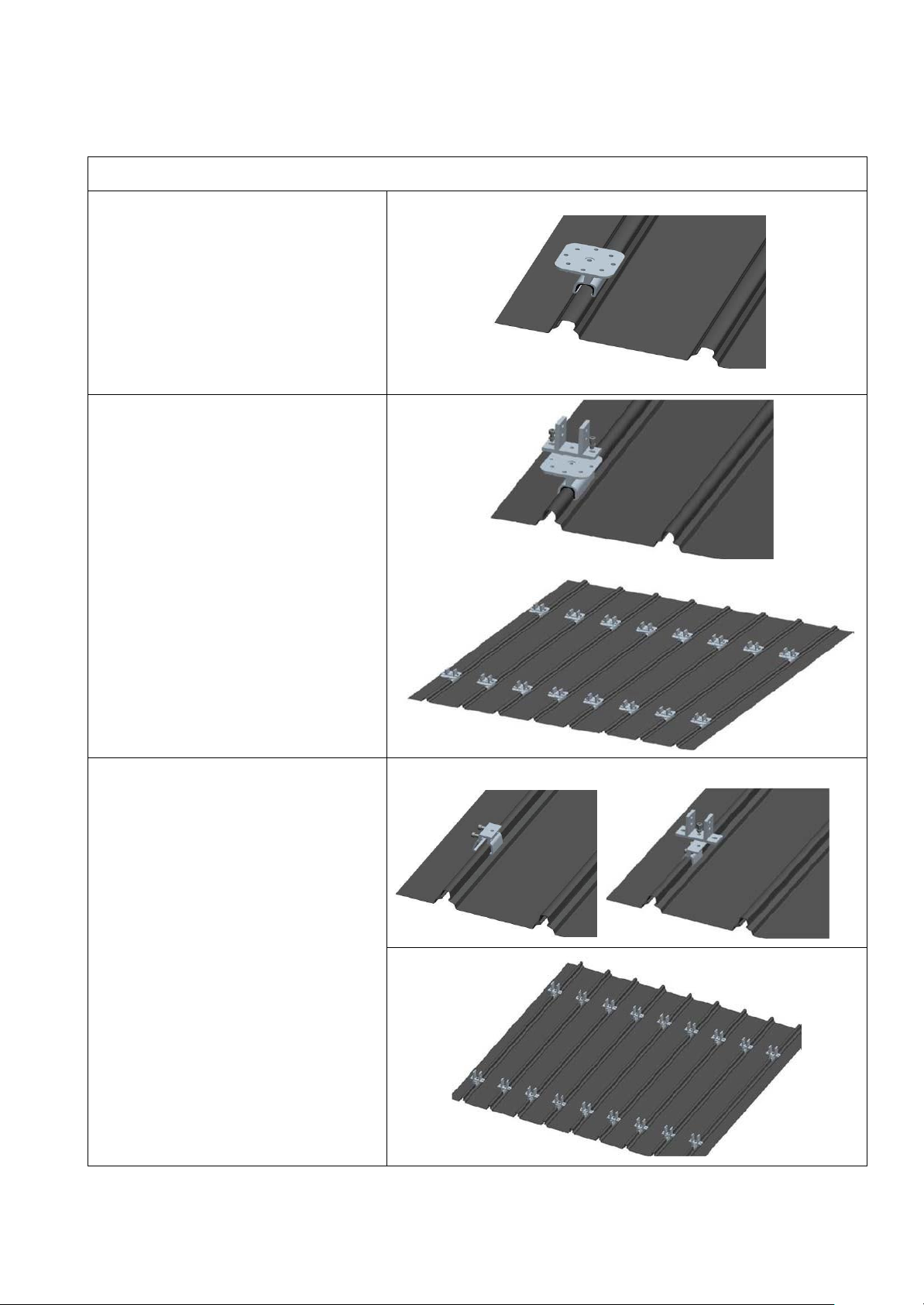
INSTALLATION INSTRUCTION
Installation of Kliplok Clamp and fix foot
1. Mark the installation points of the
clips according to your plans and the
fixing spacing table in certification
Note: The EPDM rubber pad play
the role of waterproof.
2. Place the fix foot on the Kliplok
700 Clamp, and connect them by
tightening 2 pcs M8 x 20 Bolt.
Note: Please make sure the clips
are in a line.
3. Install the Kliplok 406 Clamp
and Fix foot as the installation of
Kliplok 700.
Page 14
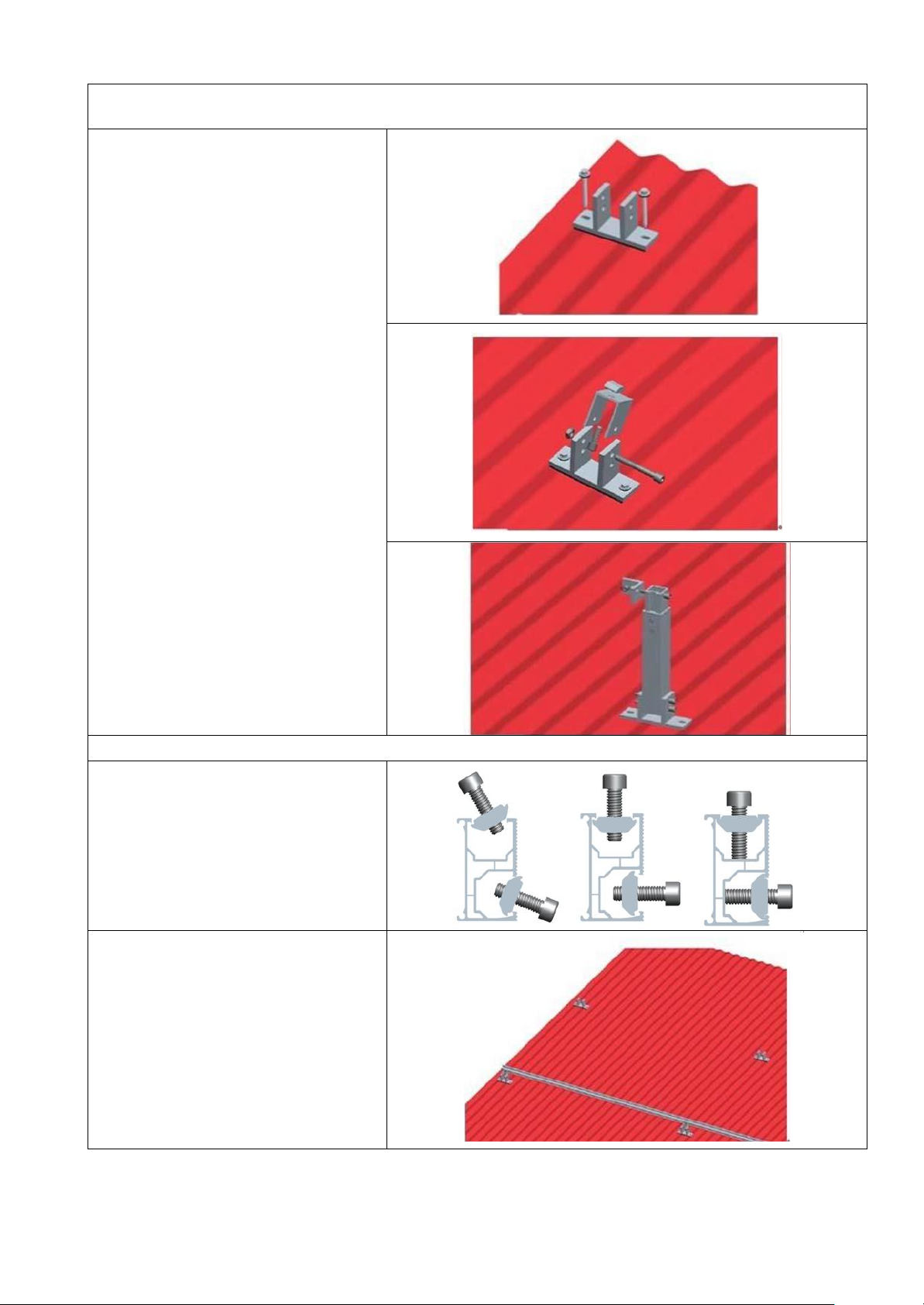
Install the front foot and rear leg
1. Determine the positions of the
front foot and adjustable rear leg
according to your plans and the
fixing spacing table in certification.
2. Fix the front foot to the rafter
using 2 pcs ST6.3*80 self-tapping
screws.
3. Fix the rear leg to the rafter
using 2 pcs ST 6.3*80 self-tapping
screws.
4. Make sure the front foot and rear
leg in a line.
Note: The EPDM rubber pad play
the role of waterproof.
Install the Rail
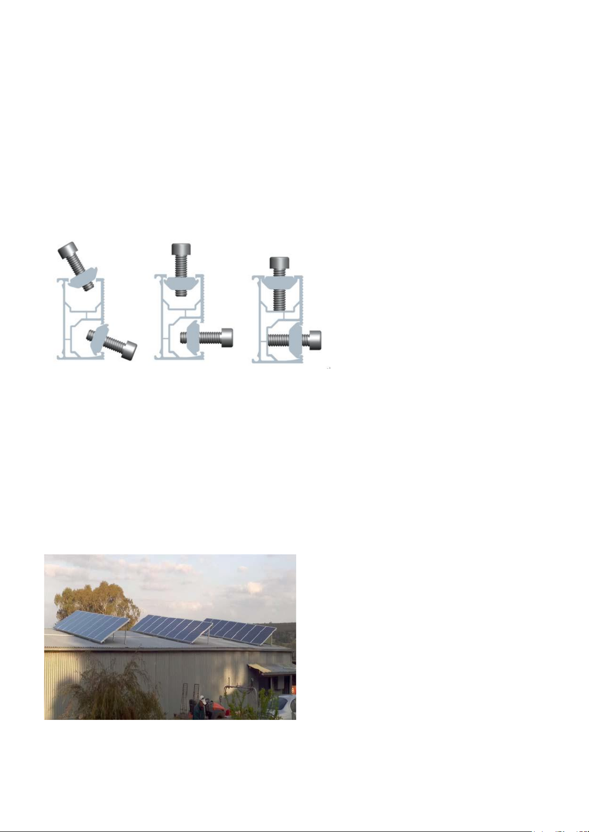
a. Tilt in the T module
Only Four steps to quick mount the
tilt-in T-module into
ANTAISOLAR/ANTAI rail channel
b. Connect the rail
1. Insert the tilt-in module (Front
foot) into the side channel of the
ANTAISOLAR/ANTAI rail as the
step above shown.
2. Adjust the rail to be level.
3. Fasten the bolt.
Note: Fasten firmly in place by
torque bolt to 10Nm.
Page 15
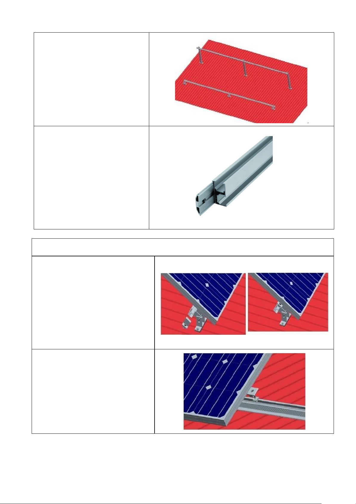
c. Loosen the 2 Hex screws in the
rear leg and adjust the length of
rear legs as demanding angle.
Install the rail with the rear leg
as the step b.
d. Connect the rail splice kits Install
the splice to connect multiple
rails together. Slide the splices
on the rear side of the pre-
assembled rails halfway to the
side. Fasten the first M8 bolt
firmly using the Allen key. Now
slide the next rail segment into
the splice. Tighten the second
M8 bolt .The connection is
finished.
Install the module
a. Place the solar module on the rails,
slide the end clamp tightly against the
solar module and fasten tightly using
the Allen bolt.
b. Slide the pre-assembled inter
clamp into the rails from above,
place it firmly against the module
and fasten loosely.
Note: Install the grounding equipment
as the next step
Page 16
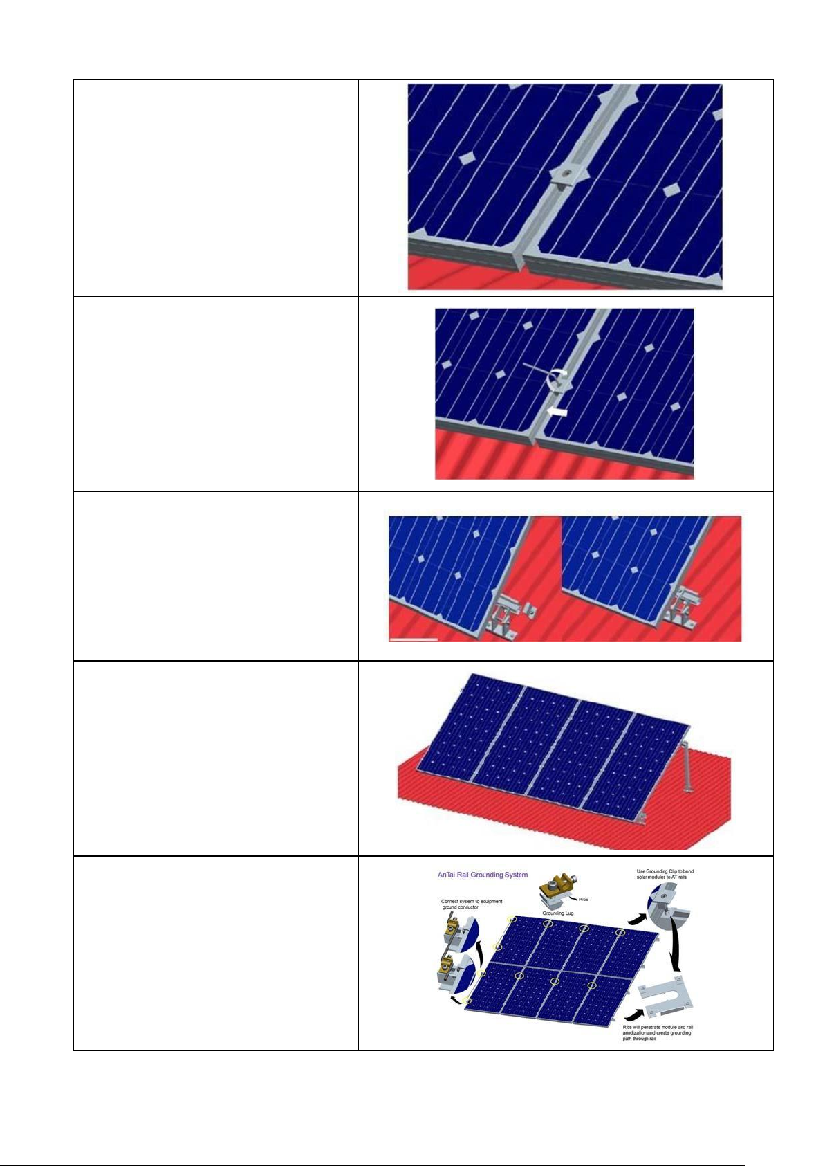
c. Slide the next module against the
previously installed module and
tighten the inter clamp using the Allen
key, Take care that the anti-slip
protection sits in the rail channel of
the lowest row of rails.
d. Slide the next module against the
previously installed module and
tighten the inter clamp using the Allen
key, Take care that the anti-slip
protection sits in the rail channel of
the lowest row of rails.
d. Place the last module in the row
on the rails (with the first row of
modules, take care that the anti-
slip protection sits properly in the
rail channel) and fasten the last
mid clamp and the end clamp
using the Allen key.
e. Leg Strut and fix foot can be
adjusted.
ANTAISOLAR/ANTAI rail grounding
system
 Loading...