

Page 1
SECCIÓN 1
ES MANUAL DE USO |
SECTION 1
FR NOTICE D’EMPLOI |
KAPITEL 1
DE BEDIENUNGSANLEITUNG |
BI-AMPLIFIED MINIBOX SPEAKERS
DIFFUSORI MINIBOX BI-AMPLIFICATI
ENCEINTES MINIBOX BI-AMPLIFIÉES
BI-AMPING MINIBOX-LAUTSPRECHER
DIFUSORES MINIBOX BIAMPLIFICADOS
BBM 3 | BBM 5 | BBM 8
SEZIONE 1
SECTION 1
EN USER MANUAL |
IT MANUALE D’USO |
Page 2
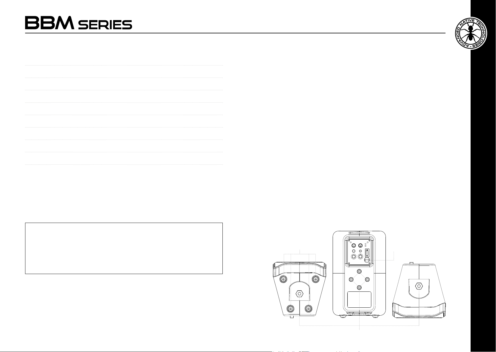
TABLE OF CONTENTS
1 | Introduction 3
2 | Installation 3
3 | Description 4
3.1 | Inputs & Controls 5
3.2 | Power supply section 6
4 | Optional accessories 7
5 | Troubleshooting 8
6 | Technical specications 8
7 | Notes 42
1 | INTRODUCTION
Thank you for choosing a A.N.T - Advanced Native Technologies - product!
In our BBM series of speakers, we have put our passion and our technological
background gained over the years, to offer products that meet your needs,
maintaining the quality over time.
All models ensure an extended frequency response with a clean and
undistorted sound, even at high sound level pressures.
Expressly designed to be immediately used in a very user friendly way, this
series is the answer to the needs of those who want a compact sound system
capable of providing excellent performance, versatility of connections and
controls, and the best value for its product range.
Please, dedicate some minutes to read this instruction manual in order to
quickly achieve the best performances from this product.
For safety precautions, warranty and disposal, please refer to attached
Section 2.
For further information about all A.N.T products catalog, please visit our
website: www.ant-intomusic.com
2 | INSTALLATION
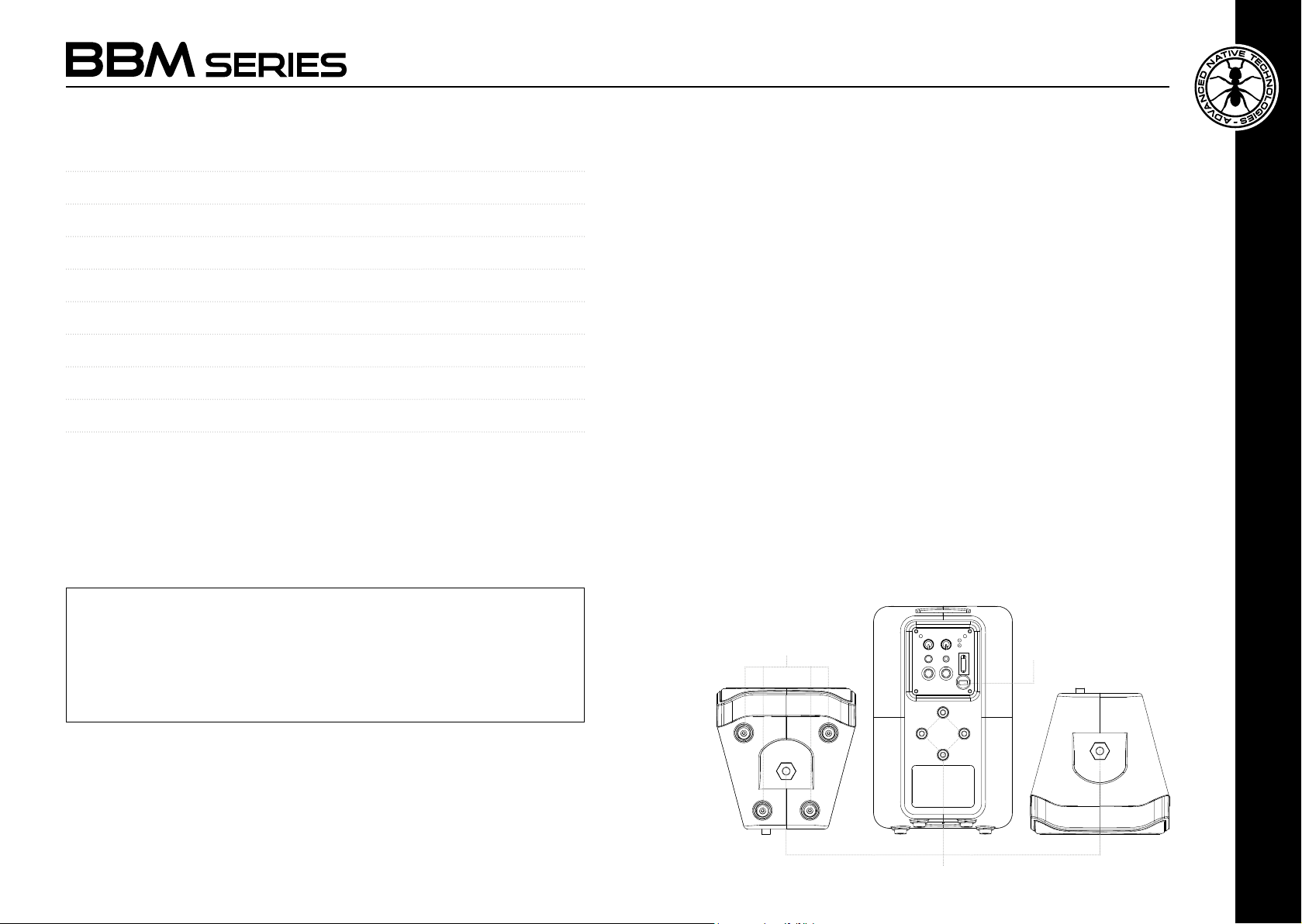
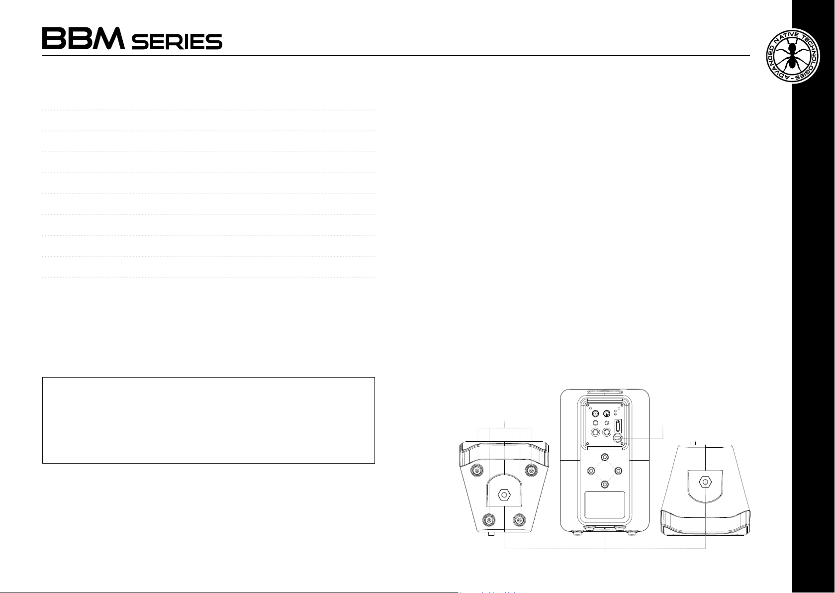
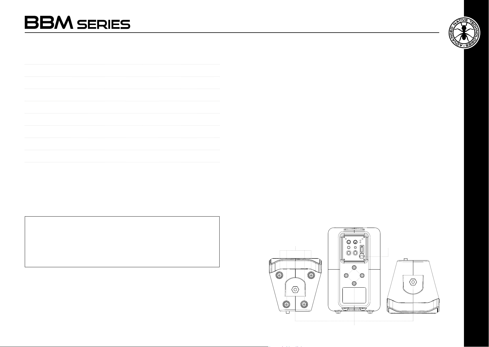
BBM speakers feature:
A | Fly points for speaker installation on wall or ceiling.
B | AC power cord with integrated plug.
C | Anti-slip rubber feet.
PACKAGE CONTENT
• 1x Minibox active speaker
• 1x User Manual - Section 1
• 1x User Manual - Section 2
The warnings in this manual must be observed together with the
“User manual - Section 2”.
User manual | BBM Series
2
C B
A
BBM Series | User manual
ENGLISH
3
Page 3
3 | DESCRIPTION
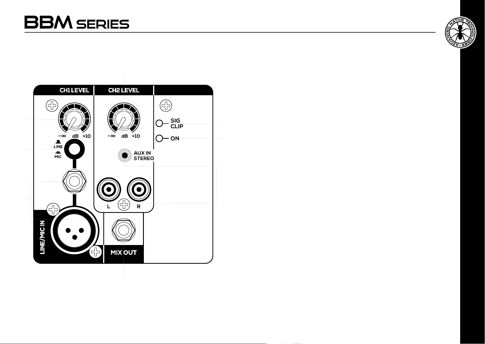
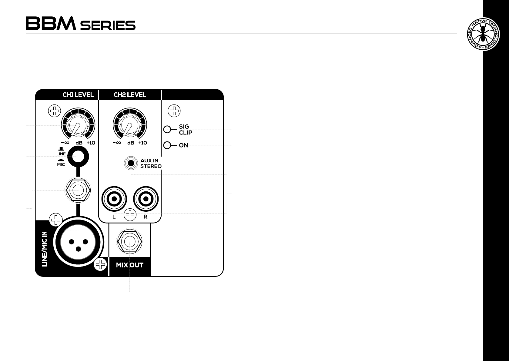
3.1 | INPUTS & CONTROLS
5
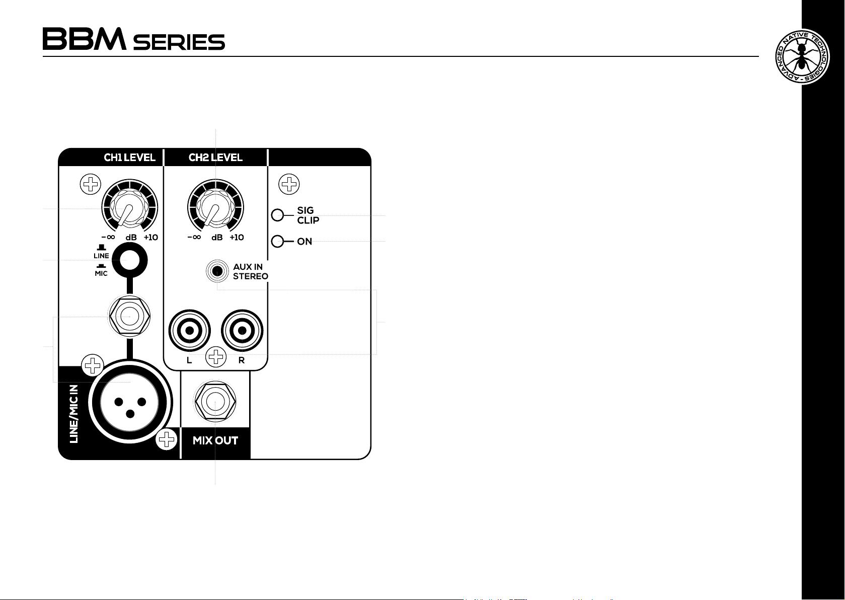
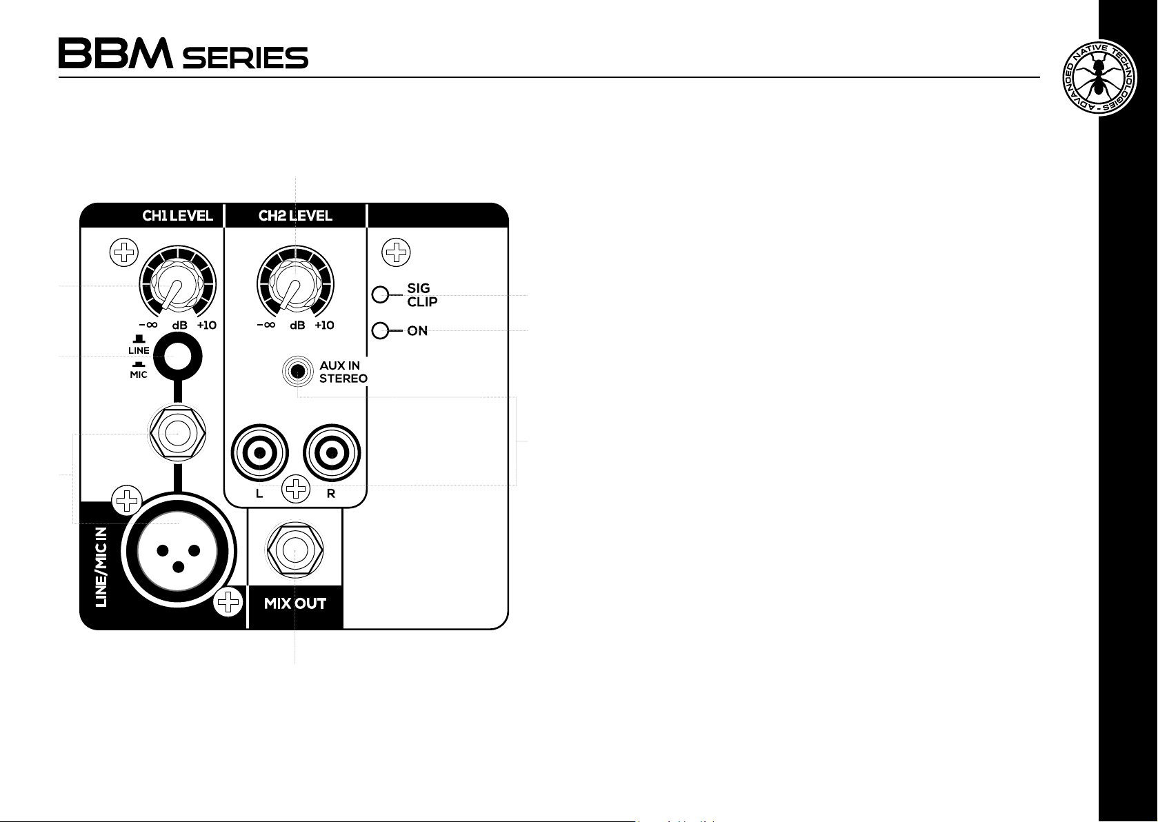
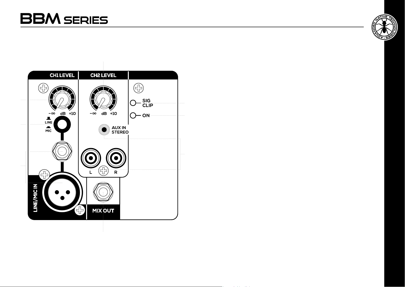
1 CH1 - MIC/LINE INPUT
Balanced microphone (XLR-F) and line (6,35 mm-1/4” jack) input. The
BBM3 model features the 6.35 mm-1/4” jack connector only. You may
also use a microphone cable with unbalanced 6.35mm jack.
2 CH1 - LINE/MIC SWITCH
Place the switch in LINE to use a line-level source or MIC for use with
a microphone
3
7
3 CH1 - LEVEL
This knob adjusts channel one level, turn it to the right to raise the level,
8
2
to the left to decrease it.
4 CH2 - LINE INPUT
Input with RCA sockets and 3,5mm mini-jack. The BBM3 model features
the mini-jack connector only.
5 CH2 - LEVEL
This knob adjusts channel two level, turn it to the right to raise the level,
4
1
to the left to decrease it.
6 MIX OUT
This 6,35 mm-1/4” jack output provides a balanced line-level signal,
useful for connection to another active speaker.
7 LED SIG/CLIP
The CLIP indicator turns on when the speaker signal is distorted. In this
case reduce the active channel(s) level(s).
User manual | BBM Series
4
8 LED ON
The ON indicator is lit when the unit is plugged to mains, and the power
switch is ON.
6
ENGLISH
BBM Series | User manual
5
Page 4
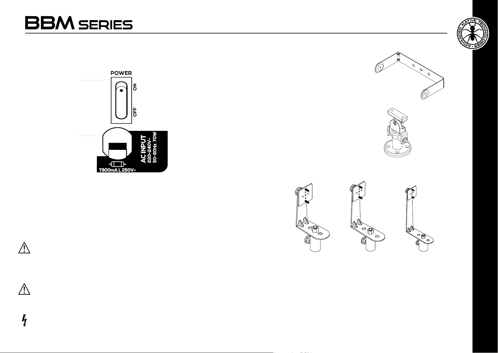
3.2 | POWER SUPPLY
1
2
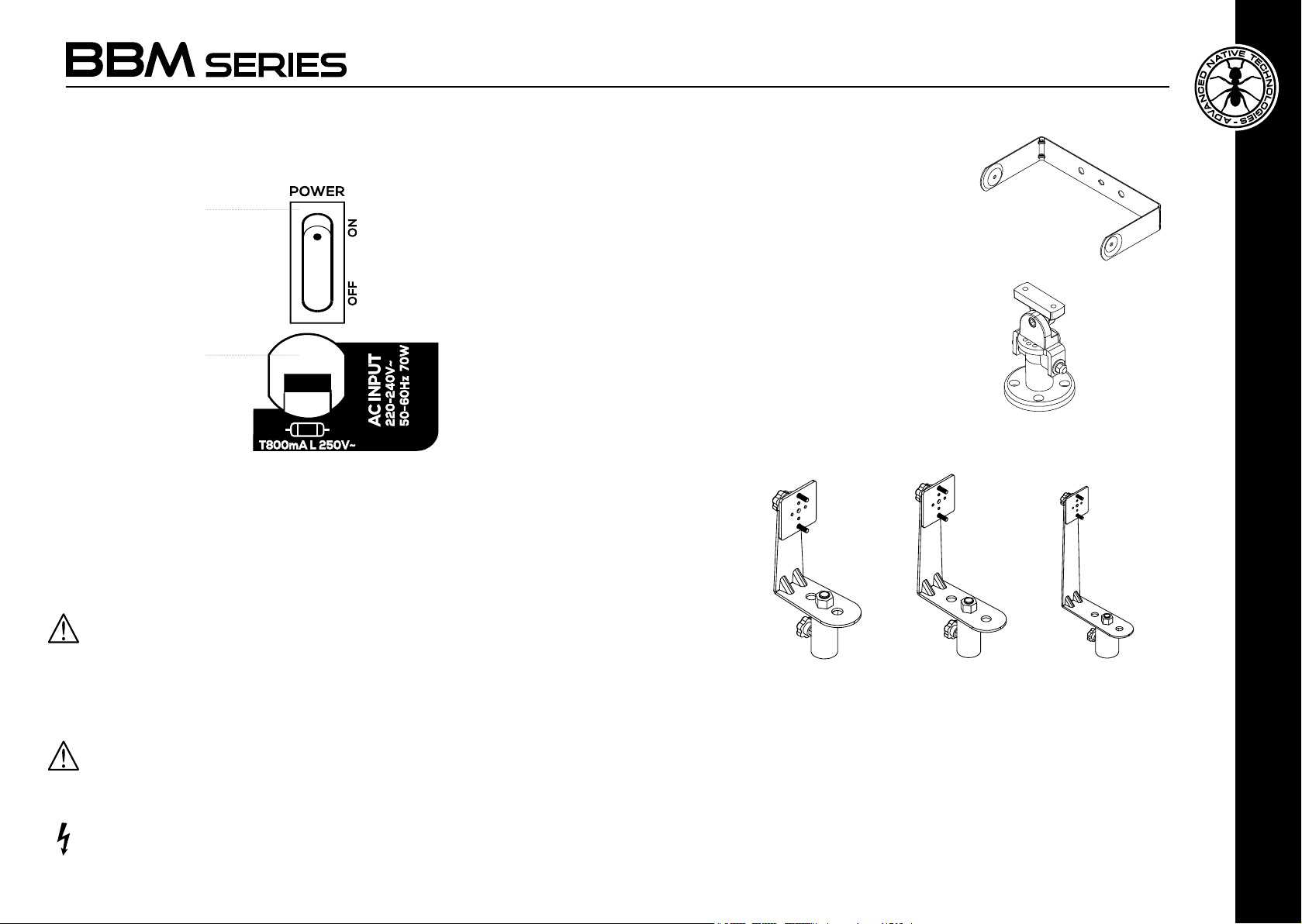
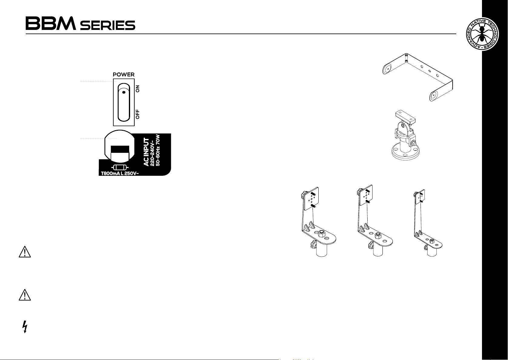
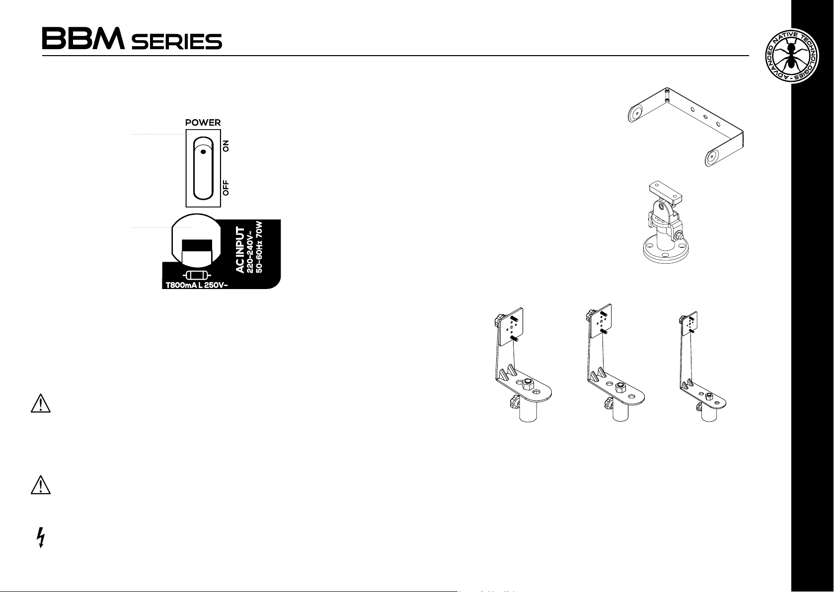
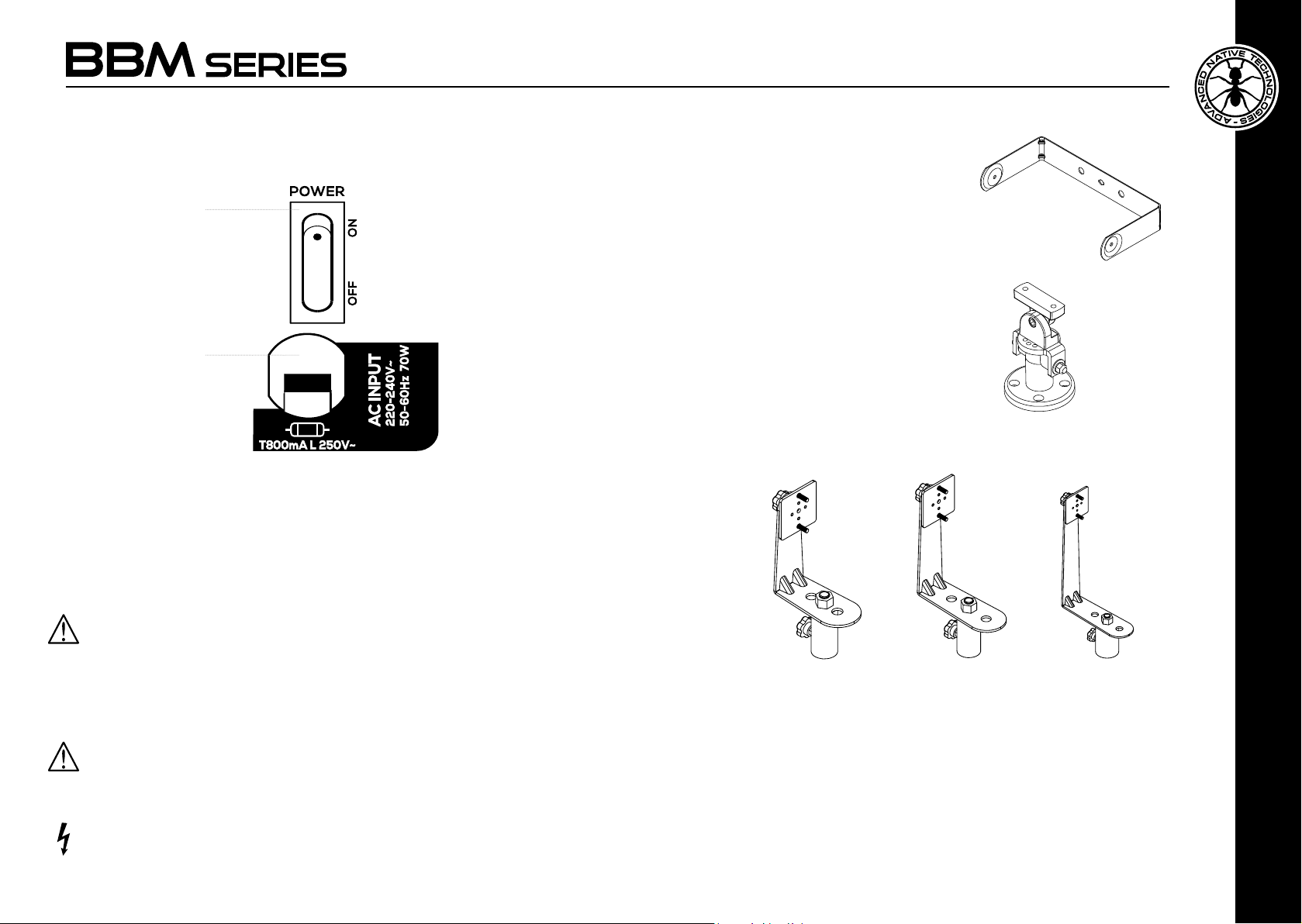
1 POWER ON/OFF
Use this switch to turn On/Off the unit.
2 AC POWER CORD
Insert this cord in mains socket.
Make sure the device is switched off before connecting the cord to the mains.
For your safety, never disconnect the earth lead.
Note: The protection fuse is placed in a printed circuit board inside the unit.
CAUTION: Replace the fuse only with one of the same type and with the same value.
Do not open the unit to replace the fuse, but contact an authorized service center.
If the fuse blows repeatedly, contact an authorized service center.
4 | OPTIONAL ACCESSORIES
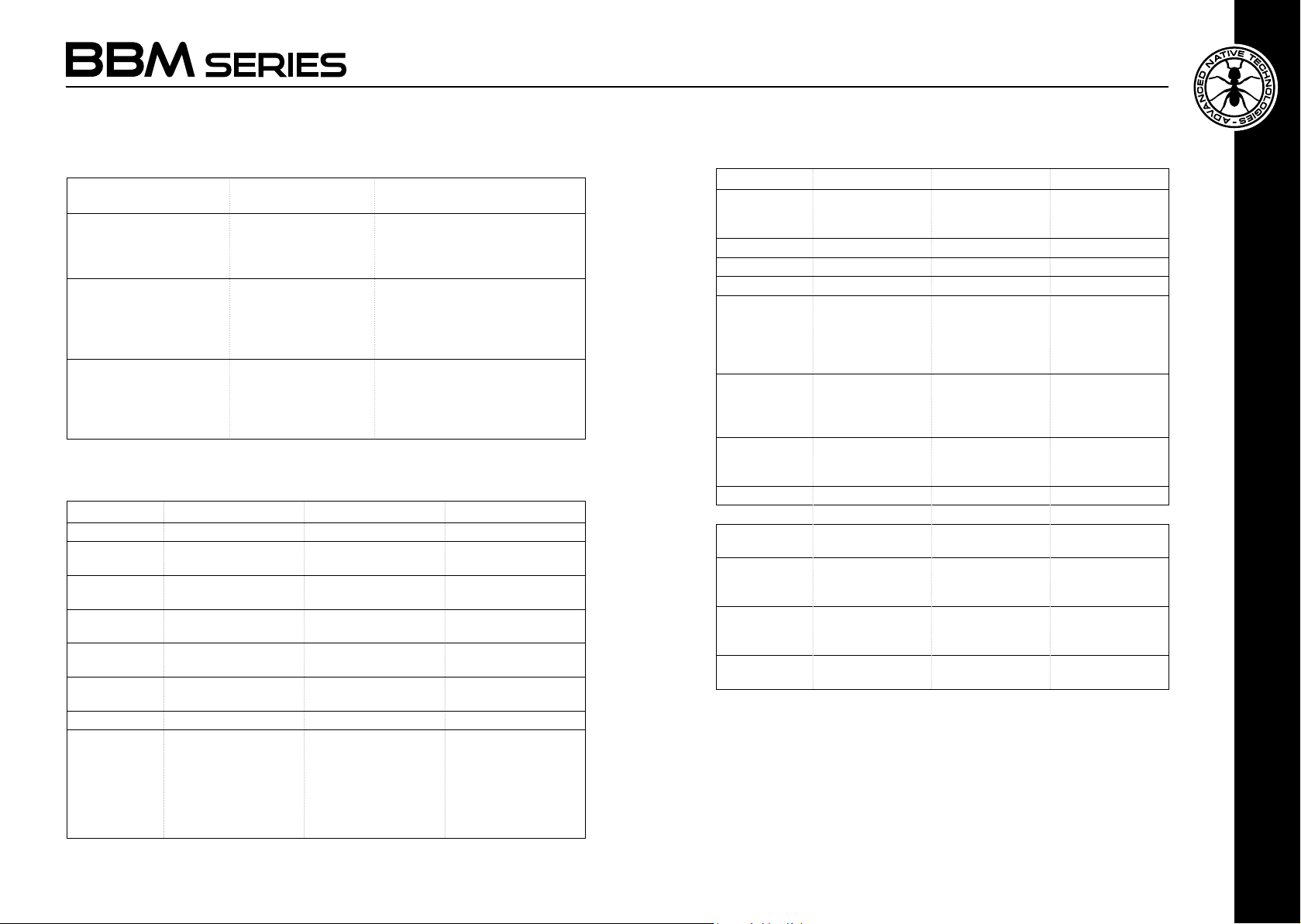
• Wall installation kit by U brackets
BBM-WB3U
BBM-WB5U
BBM-WB8U
• Wall or ceiling swivelling mounting kit,
allowing speakers independent
rotation and tilting
BBM-358Y
• Stand adaptor kit with L brackets
BBM-SA30 BBM-SA50 BBM-SA80
WARNING!
Never remove the product’s front protection mesh. In order to prevent electric
shock hazard, in the event of accidental damage or replacement of the protection
mesh (which must be carried out by a service center), disconnect the power supply
immediately.
CAUTION: To reduce the risk of electric shock, do not connect the appliance to
the power supply while the mesh is removed.
User manual | BBM Series
6
ATTENTION: Contact our customer service for accessories to be used.
It's mandatory to use only supports, brackets and accessories made
by A.E.B Industriale Srl.
It is absolutely forbidden to perforate the device cabinet or to x by any
other kind of mechanical support by adhesive tape. In case of particular
installations, which are not described in this manual, please contact our
technical service for the list of available accessories.
No liability is assumed for the inappropriate use of accessories or
additional devices not suitable for the purpose.
BBM Series | User manual
ENGLISH
7
Page 5

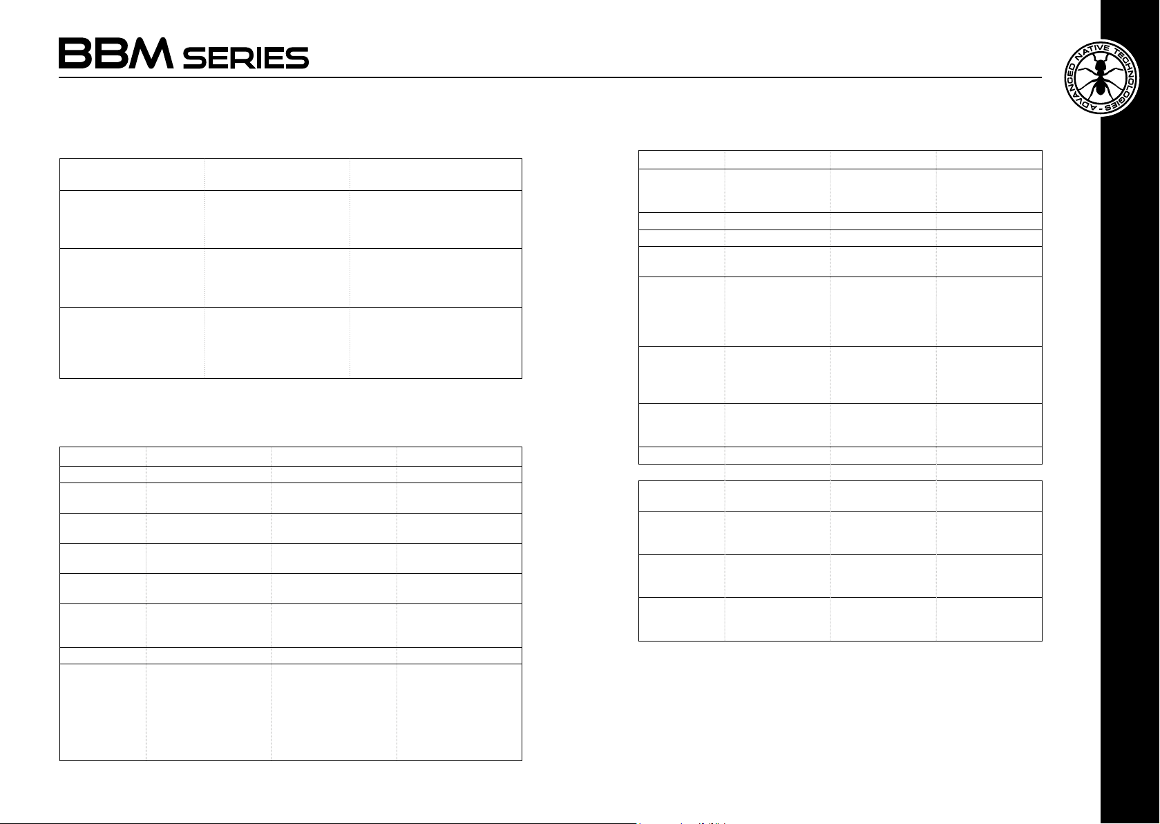
5 | TROUBLESHOOTING
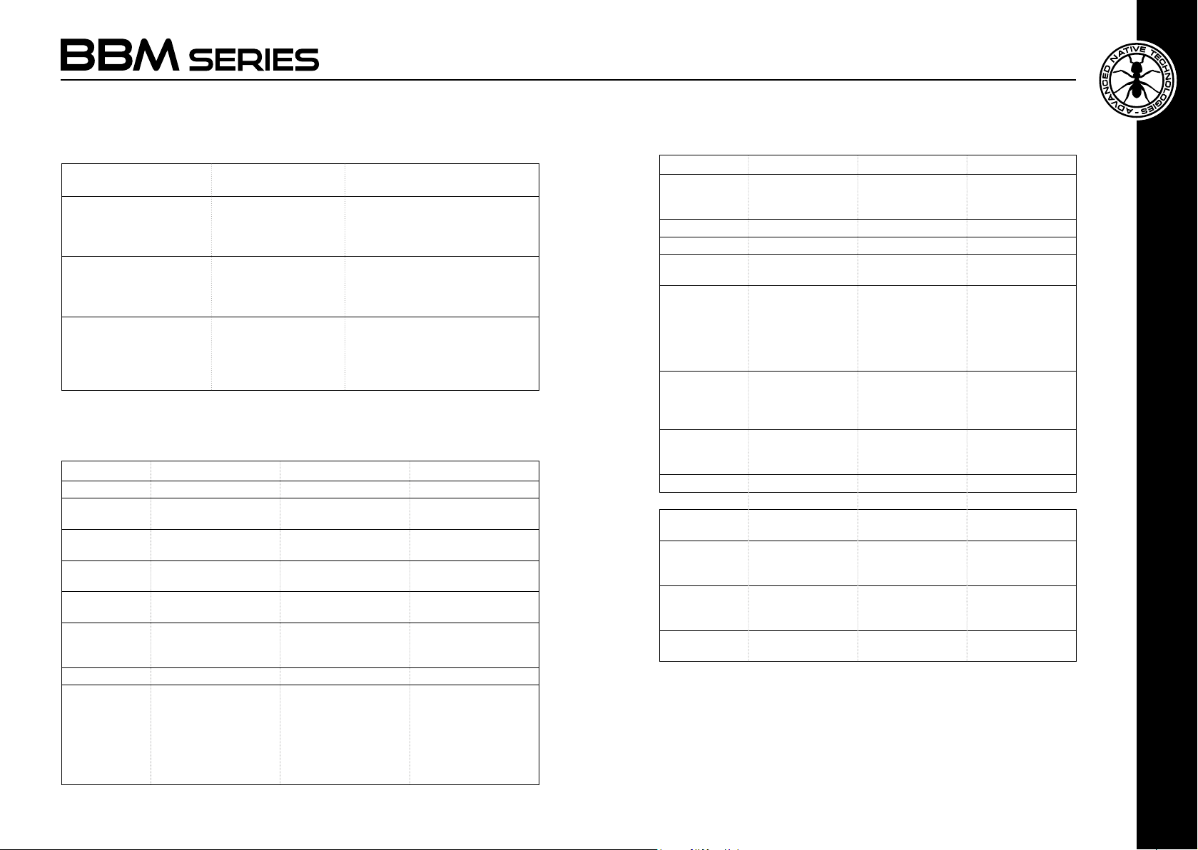
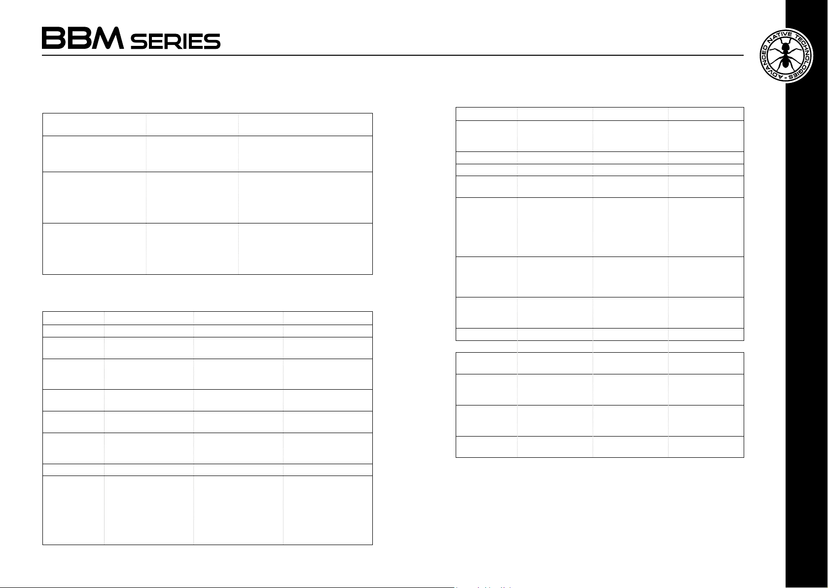
PROBLEM LEDS SOLUTION
No sound or very low
sound level
Distortion
Power LED turned off.
Power LED turned on, but
low input channels LEVEL.
CLIP LED on.
Make sure the device is properly
connected to the mains outlet
Check the connections between
the sources and the inputs.
Raise channels LEVEL.
Cut input LEVEL controls
Make sure you haven't
connected a line level signal to
the MIC input
6 | TECHNICAL SPECIFICATIONS
BBM 3 BBM 5 BBM 8
System type Vented enclosure, 2-way Vented enclosure, 2-way Vented enclosure, 2-way
LF 3.5” custom speaker -
HF 0.8” neodymium dome
Amplication
type (LF+HF)
Peak power
(LF+HF)
Frequency
response
(-10dB)
SPL - MAX 103 dB 109 dB 112 dB
I/O Connectors CH1 MIC/LINE: 6,35mm
1” V.C.
tweeter
Class D + Class A/B Class D + Class A/B Class D + Class A/B
80W 100W 120W
140Hz-20kHz 100Hz-20kHz 55Hz-20kHz
(1/4”) jack
CH 2 IN: 3,5mm. minijack
LINE OUT: 6,35mm
(1/4”) jack
5” custom speaker 1” V.C.
1” neodymium dome
tweeter
CH1 MIC IN: XLR-F
CH1 LINE IN: 6,35mm
(1/4”) jack
CH 2 IN: 3,5mm. minijack and 2 RCA
LINE OUT: 6,35mm
(1/4”) jack
8” custom speaker 1” V.C.
1” neodymium dome
tweeter
CH1 MIC IN: XLR-F
CH1 LINE IN: 6,35mm
(1/4”) jack
CH 2 IN: 3,5mm. minijack and 2 RCA
LINE OUT: 6,35mm
(1/4”) jack
BBM 3 BBM 5 BBM 8
Controls CH1 LEVEL, LINE/
Power supply 220-240V~ 50-60Hz 220-240V~ 50-60Hz 220-240V~ 50-60Hz
Fuse T800mA L 250V~ T800mA L 250V~ T800mA L 250V~
Power
Consumption
Suspension
system
Materials Injection-Molded
Dimensions
(W x H x D)
Weight 2.1 Kg 4.63 lbs 3.7 Kg 8.16 lbs 6.3 Kg 13.89 lbs
OPTIONAL
ACCESSORIES
• Brackets kit for
wall mounting
• Brackets
rotation and
tiltiing kit for
wall/ceiling
mounting
• Tripod
mount kit
MIC switch, CH2
LEVEL.
40W 70W 70W
2 M6 - top/under for
U bracket mount
4 M5 - rear for Y and
SA brackets
ABS cabinet
Perforated Steel
Grille
5.29''(134.3mm) x
8.68''(220.4mm) x
5.37''(136.4mm)
BBM-WB3U BBM-WB5U BBM-WB8U
BBM-358Y BBM-358Y BBM-358Y
BBM-SA30 BBM-SA50 BBM-SA80
CH1 LEVEL, LINE/
MIC switch, CH2
LEVEL.
2 M6 - top/under for
U bracket mount
4 M5 - rear for Y and
SA brackets
Injection-Molded
ABS cabinet
Perforated Steel
Grille
6.71''(170.5mm) x
10.7''(272mm) x
6.76''(171.8mm)
CH1 LEVEL, LINE/
MIC switch, CH2
LEVEL.
2 M6 - top/under for
U bracket mount
4 M5 - rear for Y and
SA brackets
Injection-Molded
ABS cabinet
Perforated Steel
Grille
9.84''(250mm) x
15.75''(400mm) x
9.88''(251mm)
ENGLISH
User manual | BBM Series
8
BBM Series | User manual
9
9
Page 6
INDICE
1 | Introduzione 11
2 | Installazione 11
3 | Descrizione 12
3.1 | Ingressi & controlli 13
3.2 | Alimentazione 14
4 | Accessori opzionali 15
5 | Soluzione dei problemi 16
6 | Speciche tecniche 16
7 | Notes 42
1 | INTRODUZIONE
Grazie per aver acquistato un prodotto A.N.T - Advanced Native Technologies!
Nei diffusori acustici della serie BBM abbiamo profuso la nostra passione
ed il nostro know-how maturato nel corso degli anni per offrirvi un prodotto
che soddis le vostre esigenze e mantenga la sua qualità nel tempo.
Tutti i modelli garantiscono un’estesa risposta in frequenza con un suono
pulito e senza distorsioni anche a volumi molto alti.
Progettati appositamente per un utilizzo estremamente immediato e semplice,
rispondono alle esigenze di quanti desiderano un sistema audio compatto
in grado di fornire ottime prestazioni, ampia versatilità di connessioni e
controlli, e il miglior rapporto qualità-prezzo possibile per questa categoria.
Ritagliatevi qualche minuto per leggere questo manuale di istruzioni in modo
tale da ottenere rapidamente il massimo delle performance da questo prodotto.
Per le istruzioni relative a sicurezza, le precauzioni, la garanzia e lo smaltimento
fate riferimento all'allegato sezione 2.
Per ulteriori informazioni su tutti i prodotti del catalogo ANT consultate il
nostro sito: www.ant-intomusic.com
2 | INSTALLAZIONE
I diffusori BBM sono forniti di:
A | Punti di ssaggio per l’installazione del diffusore a parete o softto.
B | Cavo di alimentazione con spina elettrica integrata.
C | Piedini antiscivolamento in gomma.
CONTENUTO DELL’IMBALLO
• 1x Diffusore Minibox attivo
• 1x Manuale d’uso - Sezione 1
• 1x Manuale d’uso - Sezione 2
Le avvertenze del presente manuale devono essere osservate
congiuntamente al “MANUALE D’USO - SEZIONE 2”.
Manuale d’uso
10
| Serie BBM
C B
A
Serie BBM | Manuale d’uso
ITALIANO
11
Page 7
3 | DESCRIZIONE
3.1 | INGRESSI & CONTROLLI
5
1 CH1 - MIC/LINE INPUT
Ingresso microfono bilanciato (XLR-F) e linea (jack da 6,35 mm-1/4”).
Il modello BBM3 è fornito con il solo connettore jack da 6,35 mm-1/4”.
È possibile usare anche un cavo microfonico jack non bilanciato.
2 CH1 - SELETTORE LINE/MIC
Posizionate il selettore in LINE per l’utilizzo di una sorgente a livello linea
o in MIC per l’utilizzo di un microfono.
3
7
3 CH1 - LEVEL
Questa manopola regola il livello del canale 1, ruotatela verso destra per
8
2
alzare il livello, verso sinistra per diminuirlo.
4 CH2 - LINE INPUT
Ingresso su prese RCA e presa mini-jack da 3,5mm. Il modello BBM3 è
fornito con il solo connettore mini-jack.
5 CH2 - LEVEL
Questa manopola regola il livello del canale due, ruotatela verso destra
4
1
per alzare il livello, verso sinistra per diminuirlo.
6 MIX OUT
Questo connettore jack da 6,35mm. serve per inviare il segnale mix ad
un ulteriore diffusore attivo.
7 LED SIG/CLIP
Il led CLIP si accende quando il segnale raggiunge la distorsione. In
questo caso riducete il segnale dei canali in funzione.
Manuale d’uso
12
| Serie BBM
8 LED ON
Il led ON si accende quando l’apparecchio è collegato alla rete elettrica
e l'interruttore di accensione è premuto.
6
ITALIANO
Serie BBM | Manuale d’uso
13
Page 8
3.2 | ALIMENTAZIONE
1
2
1 POWER ON/OFF
Interruttore per accensione/spegnimento dell'apparecchio.
2 CAVO DI ALIMENTAZIONE
Inserite questo cavo nella presa elettrica.
Assicuratevi che l’apparecchio sia spento prima di collegarlo alla rete.
Per la vostra sicurezza, non scollegate mai il polo di terra.
Nota: il fusibile di protezione è collocato sul circuito stampato all’interno
dell’apparecchio.
ATTENZIONE: Sostituire il fusibile unicamente con uno dello stesso tipo e con gli
stessi valori. Non aprire l'unità per sostituire il fusibile, ma contattare un centro
di assistenza autorizzato.
ATTENZIONE!
Non rimuovere mai la griglia frontale di protezione del prodotto. Per prevenire il
pericolo di scossa elettrica, in caso di danneggiamento accidentale o sostituzione
della griglia di protezione (da effettuarsi presso il servizio assistenza), disconnettere
immediatamente l’alimentazione.
ATTENZIONE: Per ridurre il rischio di scosse elettriche, non connettere mai
l’alimentazione di rete all’apparecchio quando la griglia è rimossa.
Manuale d’uso
14
| Serie BBM
4 | ACCESSORI OPZIONALI
• Kit di ssaggio del diffusore
a parete tramite staffe a U
BBM-WB3U
BBM-WB5U
BBM-WB8U
• Kit di ssaggio a parete o softto con
possibilità di rotazione e
inclinazione indipendenti del diffusore
BBM-358Y
• Kit di ssaggio del diffusore su treppiede tramite staffe
BBM-SA30 BBM-SA50 BBM-SA80
ATTENZIONE: Contattare il nostro servizio clienti per gli accessori da
utilizzare a corredo. È fatto obbligo di utilizzare esclusivamente supporti,
staffe e accessori realizzati da A.E.B Industriale Srl.
È assolutamente vietato perforare il contenitore dell’apparato o ssare
qualunque altro genere di supporto meccanico mediante adesivo. In
caso di installazioni particolari e in ogni modo non descritte nel presente
manuale, contattare il nostro servizio tecnico per l’elenco degli accessori
disponibili. Si declina ogni responsabilità da un utilizzo inappropriato
degli accessori o di dispositivi aggiuntivi non idonei allo scopo.
Serie BBM | Manuale d’uso
ITALIANO
15
Page 9
5 | SOLUZIONE DEI PROBLEMI
PROBLEMA SPIE LUMINOSE SOLUZIONE
Assenza di suono o suono
troppo basso
Distorsione Led CLIP acceso
Led Power spento
LED Power acceso, ma
LEVEL dei canali di ingresso
abbassati
Assicuratevi che il diffusore sia
collegato correttamente alla presa
di corrente.
Controllate i collegamenti tra le
sorgenti e gli ingressi.
Alzate LEVEL dei canali.
Attenuate il controlo LEVEL degli
ingressi. Assicuratevi di non aver
collegato un segnale di linea
nell’ingresso MIC IN
6 | SPECIFICHE TECNICHE
BBM 3 BBM 5 BBM 8
Sistema 2-vie bass reflex 2-vie bass reflex 2-vie bass reflex
LF Altoparlante custom da
HF Driver a cupola al
Amplicatore
(LF+HF)
Potenza di picco
(LF+HF)
Risposta in
frequenza (+/10dB)
SPL - MAX 103 dB 109 dB 112 dB
Connettori I/O CH1 MIC/LINE: jack
Manuale d’uso
16
3.5” - 1” V.C.
neodimio da 0.8”
Classe D + Classe A/B Classe D + Classe A/B Classe D + Classe A/B
80W 100W 120W
140Hz-20kHz 100Hz-20kHz 55Hz-20kHz
6,35mm (1/4”)
CH 2 IN: mini-jack
3,5mm.
LINE OUT: jack 6,35mm
(1/4”)
| Serie BBM
Altoparlante custom da
5” - 1” V.C.
Driver a cupola al
neodimio da 1”
CH1 MIC IN: XLR-F
CH1 LINE IN: jack
6,35mm (1/4”)
CH 2 IN: mini-jack
3,5mm. e 2 RCA
LINE OUT: jack 6,35mm
(1/4”)
Altoparlante custom da
8” - 1” V.C.
Driver a cupola al
neodimio da 1”
CH1 MIC IN: XLR-F
CH1 LINE IN: jack
6,35mm (1/4”)
CH 2 IN: mini-jack
3,5mm. e 2 RCA
LINE OUT: jack 6,35mm
(1/4”)
BBM 3 BBM 5 BBM 8
Controlli CH1 LEVEL, selettore
Alimentazione 220-240V~ 50-60Hz 220-240V~ 50-60Hz 220-240V~ 50-60Hz
Fusibile T800mA L 250V~ T800mA L 250V~ T800mA L 250V~
Assorbimento di
corrente
Punti di
sospensione
Materiale
cabinet
Dimensioni
(L x H x P)
Peso 2.1 Kg 3.7 Kg 6.3 Kg
ACCESSORI
OPZIONALI
• Kit staffe U per
montaggio a
muro
• Staffa a Y per
rotazione e
inclinazione
• Kit di
montaggio su
treppiede
LINE/MIC, CH2
LEVEL.
40W 70W 70W
2 M6 - sopra e sotto
per montaggio con
staffe a U
4 M5 - posteriori per
snodo Y e staffa SA
ABS stampato a
iniezione
Griglia in acciaio
perforata
5.29''(134.3mm) x
8.68''(220.4mm) x
5.37''(136.4mm)
BBM-WB3U BBM-WB5U BBM-WB8U
BBM-358Y BBM-358Y BBM-358Y
BBM-SA30 BBM-SA50 BBM-SA80
CH1 LEVEL, selettore
LINE/MIC, CH2
LEVEL.
2 M6 - sopra e sotto
per montaggio con
staffe a U
4 M5 - posteriori per
snodo Y e staffa SA
ABS stampato a
iniezione
Griglia in acciaio
perforata
6.71''(170.5mm) x
10.7''(272mm) x
6.76''(171.8mm)
CH1 LEVEL,
selettore LINE/
MIC, CH2 LEVEL.
2 M6 - sopra e sotto
per montaggio con
staffe a U
4 M5 - posteriori per
snodo Y e staffa SA
ABS stampato a
iniezione
Griglia in acciaio
perforata
9.84''(250mm) x
15.75''(400mm) x
9.88''(251mm)
Serie BBM | Manuale d’uso
17
17
ITALIANO
Page 10
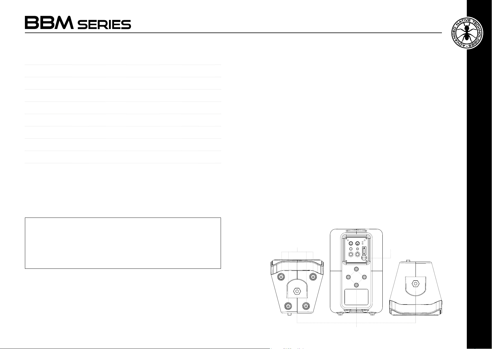
TABLE DES MATIÈRES
1 | Introduction 19
2 | Installation 19
3 | Description 20
3.1 | Entrées & contrôles 21
3.2 | Alimentation 22
4 | Accessoires en option 23
5 | Dépannage 24
6 | Spécications techniques 24
7 | Notes 42
1 | INTRODUCTION
Nous vous remercions d’avoir acheté un produit
Technologies
Les enceintes acoustiques de la série
grande passion pour notre métier et de notre expérience pluriannuelle. Elles
ont été développées pour vous offrir un produit répondant à toutes vos
exigences et attentes, tout en maintenant durablement ses performances
et sa qualité de haut niveau.
Tous les modèles garantissent une réponse en fréquence étendue avec
un son propre et sans distorsions même à des volumes très élevés.
Conçues spéciquement pour une utilisation extrêmement intuitive et
simple, elles répondent aux besoins de ceux qui veulent un système audio
capable de fournir d’excellentes performances, une grande polyvalence de
connexions et de contrôles, sans oublier le meilleur rapport qualité-prix
possible pour cette catégorie. Les quelques instants que vous consacrerez
à la lecture de cette notice d’emploi vous permettront de bien connaître
ce produit et par là même de bénécier pleinement de ses performances.
Pour les consignes de sécurité, les précautions, la garantie et l’élimination,
se référer à la section 2. Pour d’autres informations sur tous les produits
du catalogue A.N.T, rendez-vous sur notre site www.ant-intomusic.com
!
BBM
2 | INSTALLATION
Les enceintes BBM sont équipées de :
A | Points de xation pour l’installation de l’enceinte au mur ou au plafond.
B | Cordon d’alimentation avec prise électrique intégrée.
C | Pieds en caoutchouc anti-dérapant.
CONTENU DE L’EMBALLAGE
A.N.T - Advanced Native
sont le fruit à la fois de notre
• 1 enceinte Minibox active
• 1 notice d’emploi - Section 1
• 1 notice d’emploi - Section 2
Respecter impérativement les avertissements ou mises en garde
contenus dans la présente notice d’emploi ainsi que les indications
de la « „NOTICE D’EMPLOI - SECTION 2».
Notice d’emploi | Serie BBM
18
C B
A
Serie BBM | Notice d’emploi
FRANÇAIS
19
Page 11
3 | DESCRIPTION
3.1 | ENTRÉES & CONTRÔLES
5
1 CH1 - MIC/LINE INPUT
Entrée micro symétrique (XLR-F) et ligne (jack de 6,35 mm-1/4”).
Le modèle BBM3 est fourni avec le connecteur Jack 6,35 mm-1/4”
uniquement. Il est possible d’utiliser un câble micro jack non symétrique.
2 CH1 - SÉLECTEUR LINE/MIC
Réglez le sélecteur sur LINE pour utiliser une source au niveau ligne ou
en MIC pour une utilisation microphone.
3
7
3 CH1 - LEVEL
Ce bouton ajuste le volume du canal 1, tournez-le vers la droite pour
8
2
augmenter le volume, vers la gauche pour le diminuer.
4 CH2 - LINE INPUT
Entrée sur prises RCA et prise mini-jack de 3,5 mm. Le modèle BBM3
est fourni avec le connecteur mini-jack uniquement.
5 CH2 - LEVEL
Ce bouton ajuste le volume du canal 2, tournez-le vers la droite pour
4
1
augmenter le volume, vers la gauche pour le diminuer.
6 MIX OUT
Ce connecteur jack 6.35 mm sert à envoyer le signal de mixage à une
autre enceinte active.
7 LED SIG/CLIP
La led CLIP s’allume lorsque le signal arrive à distorsion. Dans ce cas,
réduisez le signal des canaux opérationnels.
Notice d’emploi | Serie BBM
20
8 LED ON
La led ON s’allume lorsque l’appareil est branché sur le secteur et le
contacteur d’allumage est enfoncé.
6
FRANÇAIS
Serie BBM | Notice d’emploi
21
Page 12
3.2 | ALIMENTATION
1
2
1 POWER ON/OFF
Interrupteur pour allumer/éteindre l’appareil.
2 CÂBLE D’ALIMENTATION
Insérez ce câble dans la prise électrique.
Assurez-vous que l’appareil est éteint avant de le connecter au réseau.
Pour votre sécurité, ne débranchez jamais la mise à la terre.
Remarque : le fusible de protection est placé sur le circuit imprimé à l’intérieur
de l’appareil.
ATTENTION : Remplacez le fusible uniquement par un fusible du même type
et avec les mêmes valeurs. N’ouvrez pas l’unité pour remplacer le fusible, mais
contactez un centre de service agréé.
Si le fusible continue à sauter, contactez un centre de service agréé.
ATTENTION !
Ne pas déposer la grille frontale de protection du produit Pour éviter tout risque
d’électrocution, en cas de dommage accidentel ou de remplacement de la grille
de protection (à effectuer par le service d’assistance), coupez immédiatement
l’alimentation électrique.
ATTENTION : Pour réduire le risque d’électrocution, ne branchez jamais
l’alimentation électrique à l’appareil lorsque la grille est retirée.
4 | ACCESSOIRES EN OPTION
• Kit de montage de l’enceinte
au mur avec étriers en U
BBM-WB3U
BBM-WB5U
BBM-WB8U
• Kit de montage mural ou au plafond
avec possibilité de rotation et
inclinaison de l’enceinte
BBM-358Y
• Kit de montage de l’enceinte sur trépied à l’aide d’étriers
BBM-SA30 BBM-SA50 BBM-SA80
ATTENTION : Contactez notre service clientèle pour les accessoires à
utiliser.
Il est obligatoire d’utiliser uniquement des supports, des étriers et des
accessoires fabriqués par A.E.B Industriale Srl.
Il est absolument interdit de perforer le caisson de l’appareil ou de xer
tout autre type de support mécanique au moyen d’un adhésif. Dans le cas
d’installations particulières et/ou non décrites dans ce manuel, contactez
notre service technique pour la liste des accessoires disponibles.
Aucune responsabilité n’est assumée pour l’utilisation inappropriée
d’accessoires ou d’appareils supplémentaires non adaptés à cet usage.
FRANÇAIS
Notice d’emploi | Serie BBM
22
Serie BBM | Notice d’emploi
23
Page 13
5 | DÉPANNAGE
PROBLEM LEDS LÖSUNG
Aucun son ou son trop
faible.
Distorsion Led CLIP allumée
LED Power éteinte.
LED Power allumée,
mais LEVEL des canaux
d’entrée baissés
Assurez-vous que l’enceinte est
branchée correctement à la prise de
courant.
Contrôlez les branchements entre les
sources et les entrées.
Augmentez le LEVEL des canaux.
Atténuez le contrôle LEVEL des
entrées
Assurez-vous de ne pas avoir relié de
signal de ligne à une entrée MIC IN
6 | SPÉCIFICATIONS TECHNIQUES
BBM 3 BBM 5 BBM 8
Système 2-voies bass reflex 2-voies bass reflex 2-voies bass reflex
LF Haut-parleur custom de
HF Pilote à coupole au
Amplicateur
(LF+HF)
Puissance de
crête (LF+HF)
Réponse en
fréquence
(+/-10dB)
SPL - MAX 103 dB 109 dB 112 dB
Connecteurs I/O CH1 MIC/LINE : jack
3.5” - 1” V.C.
néodyme de 0.8”
Classe D + Classe A/B Classe D + Classe A/B Classe D + Classe A/B
80W 100W 120W
140Hz-20kHz 100Hz-20kHz 55Hz-20kHz
6,35mm (1/4”)
CH 2 IN : mini-jack
3,5mm.
LINE OUT : jack 6,35mm
(1/4”)
Haut-parleur custom de
5” - 1” V.C.
Pilote à coupole au
néodyme de 1”
CH1 MIC IN : XLR-F
CH1 LINE IN : jack
6,35mm (1/4”)
CH 2 IN : mini-jack
3,5mm. et 2 RCA
LINE OUT : jack 6,35mm
(1/4”)
Haut-parleur custom de
8” - 1” V.C.
Pilote à coupole au
néodyme de 1”
CH1 MIC IN : XLR-F
CH1 LINE IN : jack
6,35mm (1/4”)
CH 2 IN : mini-jack
3,5mm. et 2 RCA
LINE OUT : jack 6,35mm
(1/4”)
BBM 3 BBM 5 BBM 8
Contrôles/
Commandes
Alimentation 220-240V~ 50-60Hz 220-240V~ 50-60Hz 220-240V~ 50-60Hz
Fusible T800mA L 250V~ T800mA L 250V~ T800mA L 250V~
Absorption de
courant
Points de
suspension
Matériel caisson ABS moulé par
Dimensions
(L x H x P)
Poids 2.1 Kg 3.7 Kg 6.3 Kg
ACCESSOIRES
EN OPTION
• Kit d’étriers en
U pour montage
mural
• Étrier en Y
pour la rotation
et l'inclinaison
• Kit de montage
sur trépied
CH1 LEVEL,
sélecteur LINE/MIC,
CH2 LEVEL.
40W 70W 70W
2 M6 - haut et bas
pour montage avec
étriers en U
4 M5 - arrière pour
articulation en Y et
étrier SA
injection
Grille en acier
perforé
5.29'’(134.3mm) x
8.68'’(220.4mm) x
5.37'’(136.4mm)
BBM-WB3U BBM-WB5U BBM-WB8U
BBM-358Y BBM-358Y BBM-358Y
BBM-SA30 BBM-SA50 BBM-SA80
CH1 LEVEL,
sélecteur LINE/MIC,
CH2 LEVEL.
2 M6 - haut et bas
pour montage avec
étriers en U
4 M5 - arrière pour
articulation en Y et
étrier SA
ABS moulé par
injection
Grille en acier
perforé
6.71''(170.5mm) x
10.7''(272mm) x
6.76''(171.8mm)
CH1 LEVEL,
sélecteur LINE/MIC,
CH2 LEVEL.
2 M6 - haut et bas
pour montage avec
étriers en U
4 M5 - arrière pour
articulation en Y et
étrier SA
ABS moulé par
injection
Grille en acier
perforé
9.84''(250mm) x
15.75''(400mm) x
9.88''(251mm)
FRANÇAIS
Notice d’emploi | Serie BBM
24
Serie BBM | Notice d’emploi
25
25
Page 14
INHALTSVERZEICHNIS
1 | EINLEITUNG 27
2 | INSTALLATION 27
3 | BESCHREIBUNG 28
3.1 | EINGÄNGE & BEDIENELEMENTE 29
3.2 | STROMVERSORGUNG 30
4 | OPTIONALES ZUBEHÖR 31
5 | FEHLERBEHEBUNG 32
6 | TECHNISCHE DATEN 32
7 | NOTES 42
1 | EINFÜHRUNG
Danke, dass Sie ein Produkt A.N.T - Advanced Native Technologies
erworben haben!
In Lautsprechern der Serie BBM spiegeln sich unsere TechnikLeidenschaft und jahrela nge Erfahrung wider. Sie erhalten so ein
Produkt, das hohen Ansprüchen gerecht wird und jahrelang hochwertige
Leistung liefert.
Alle Modelle garantieren breiten Frequenzgang mit glasklarem,
verzerrungsfreien Klang auch bei sehr hohen Lautstärken.
Sie wurden speziell für eine schnelle und einfache Bedienung entwickelt
und erfüllen die Wünsche aller, die von einem Audiosystem exzellente
Leistung, viele Anschlussmöglichkeiten und Bedienelemente und
das beste Preis-Leistungsverhältnis seiner Kategorie verlangen.
Bitte nehmen Sie sich einige Minuten Zeit, um diese Bedienungsanleitung
zu lesen, damit Sie dieses Produkt optimal nutzen können.
Für Sicherheitshinweise, Vorsichtsmaßnahmen, Gewährleistung und
Entsorgung siehe Anhang Abschnitt 2.
Weitere Informationen über alle Produkte des Katalogs von A.N.T nden
Sie auf unserer Website www.ant-intomusic.com
2 | INSTALLATION
Ausstattungselemente von BBM-Lautsprechern:
A | Befestigungspunkte für die Wand- oder Deckeninstallation
des Lautsprechers.
B | Netzkabel mit Stecker.
C | Rutschhemmer aus Gummi.
PACKUNGSINHALT
• 1 Aktiver Minibox-Lautsprecher
• 1 Bedienungsanleitung - Abschnitt 1
• 1 Bedienungsanleitung - Abschnitt 2
Die Hinweise in der vorliegenden Bedienungsanleitung sind ebenso zu
befolgen wie die in der „BEDIENUNGSANLEITUNG - ABSCHNITT 2“.
Bedienungsanleitung | BBM Serie
26
C B
A
BBM Serie | Bedienungsanleitung
DEUTSCH
27
Page 15
3 | BESCHREIBUNG
3.1 | EINGÄNGE & BEDIENELEMENTE
5
1 CH1 - MIC/LINE INPUT
Symmetrischer Mikrofon- (XLR-F) und Leitungseingang (Jack 6,35
mm-1/4”). Das Modell BBM3 ist nur mit 6,35 mm-1/4” Jack-Anschluss
ausgestattet. Es kann auch ein unsymmetrisches Mikrofonkabel
verwendet werden.
2 CH1 - LINE-/MIC-WAHLSCHALTER
Wahlschalter in LINE-Position zur Nutzung einer Quelle auf Line-Niveau;
3
7
Wahlschalter in MIC-Position: Mikroanschluss.
3 CH1 - LEVEL
8
2
Dieser Regler regelt das Level von Kanal 1; zum Anheben der Verstärkung
nach rechts drehen, zur Absenkung nach links drehen.
4 CH2 - LINE INPUT
Eingang mit RCA-Buchsen und 3,5mm Mini-Jack-Anschluss. Das Modell
BBM3 ist nur mit Mini-Jack-Anschluss ausgestattet.
5 CH2 - LEVEL
4
Dieser Regler regelt das Level von Kanal 2; zum Anheben der Verstärkung
nach rechts drehen, zur Absenkung nach links drehen.
1
6 MIX OUT
Dieser 6,35mm Jack-Anschluss sendet ein symmetrisches Line-LevelSignal an einen anderen aktiven Lautsprecher.
7 LED SIG/CLIP
Die LED-Anzeige CLIP leuchtet auf, wenn das Signal verzerrt ist. In
einem solchen Fall das Signal der aktuell aktiven Kanäle herunterdrehen.
Bedienungsanleitung | BBM Serie
28
8 LED ON
Die LED-Anzeige ON leuchtet auf, wenn das Gerät an das Stromnetz
angeschlossen ist und der Einschaltknopf gedrückt wird.
6
DEUTSCH
BBM Serie | Bedienungsanleitung
29
Page 16
3.2 | STROMVERSORGUNG
1
2
1 POWER ON/OFF
Schalter zum Ein-/Ausschalten des Gerätes.
2 STROMVERSORGUNGSKABEL
Schließen Sie dieses Kabel an die Steckdose an.
Vor dem Netzanschluss sicherstellen, dass das Gerät ausgeschaltet ist.
Zu Ihrer Sicherheit niemals die Erdung trennen.
Hinweis: die Schutzsicherung bendet sich auf der Leiterplatte im Gerät.
ACHTUNG: Sicherung nur mit einer Sicherung des gleichen Typs und mit denselben
Werten ersetzen. Öffnen Sie zum Ersetzen der Sicherung nicht das Gerät, sondern
wenden Sie sich an eine autorisierte Servicestelle.
Wenden Sie sich an eine autorisierte Servicestelle, falls die Sicherung weiterhin
herausspringt
ACHTUNG!
Niemals das dem Schutz des Produktes dienende Frontgitter entfernen. Zur
Vermeidung des Risikos elektrischer Schläge sollte bei einer unbeabsichtigten
Beschädigung oder Ersatz des Schutzgitters (der vom Kundendienst vorgenommen
wird), sofort die Stromversorgung abgeschaltet werden.
ACHTUNG: Zur Senkung des Risikos elektrischer Schläge das Gerät niemals an
das Stromnetz anschließen, wenn das Gitter abgenommen ist.
Bedienungsanleitung | BBM Serie
30
4 | OPTIONALES ZUBEHÖR
• Wandbefestigungssatz des
Lautsprechers mittels U-Bügeln
BBM-WB3U
BBM-WB5U
BBM-WB8U
• Wand- oder Deckenbefestigungssatz
für die unabhängige Schwenkung
und Neigung des Lautsprechers
BBM-358Y
• Stativ-Adaptersatz mit Bügeln
BBM-SA30 BBM-SA50 BBM-SA80
ACHTUNG: Kontaktieren Sie unseren Kundendienst für die Verwendung
des Zubehörs. Sie dürfen ausschließlich die von A.E.B Industriale Srl
hergestellten Halterungen, Bügel und Zubehörteile verwenden.
Es ist verboten, das Gehäuse des Geräts anzubohren oder jede
andere mechanische Halterung mittels Klebstoff zu befestigen.
Fordern Sie bei speziellen, nicht in dieser Anleitung beschriebenen
Installationsbedürfnissen bei unserem technischen Service die Liste
des verfügbaren Zubehörs an. Wir haften nicht für eine unsachgemäße
Verwendung des Zubehörs oder für den Zweck ungeeigneter
Zusatzvorrichtungen.
BBM Serie | Bedienungsanleitung
DEUTSCH
31
Page 17
5 | FEHLERBEHEBUNG
PROBLEM LEDS LÖSUNG
Kein oder zu leiser Klang LED Power aus
LED Power leuchtet,
jedoch LEVEL der
Eingangskanäle niedrig
eingestellt
Verzerrung LED CLIP leuchtet
Vergewissern Sie sich, dass der
Lautsprecher ordnungsgemäß an die
Netzsteckdose angeschlossen ist.
Anschlüsse zwischen Quellen und
Eingängen prüfen.
LEVEL der Kanäle anheben.
LEVEL-Regler der Eingänge
herunterdrehen
Sicherstellen, dass kein Line-Signal an
einem MIC-IN-Anschluss anliegt
6 | TECHNISCHE DATEN
BBM 3 BBM 5 BBM 8
System 2-Wege-Bassreflex 2-Wege-Bassreflex 2-Wege-Bassreflex
LF Custom-Lautsprecher
HF Neodym-Dome-
Lautsprecher
(LF+HF)
Spitzenleistung
(LF+HF)
Frequenzgang
(+/-10dB)
SPL - MAX 103 dB 109 dB 112 dB
I-/O-Anschlüsse CH1 MIC/LINE: Jack
3.5” - 1” V.C.
Hochtöner 0.8”
Class D + Class A/B Class D + Class A/B Class D + Class A/B
80W 100W 120W
140Hz-20kHz 100Hz-20kHz 55Hz-20kHz
6,35mm (1/4”)
CH 2 IN: Mini-Jack
3,5mm.
LINE OUT: Jack 6,35mm
(1/4”)
Custom-Lautsprecher
5” - 1” V.C.
Neodym-DomeHochtöner 1”
CH1 MIC IN: XLR-F
CH1 LINE IN: Jack
6,35mm (1/4”)
CH 2 IN: Mini-Jack
3,5mm. und 2 RCA
LINE OUT: Jack 6,35mm
(1/4”)
Custom-Lautsprecher
8” - 1” V.C.
Neodym-DomeHochtöner 1”
CH1 MIC IN: XLR-F
CH1 LINE IN: Jack
6,35mm (1/4”)
CH 2 IN: Mini-Jack
3,5mm. und 2 RCA
LINE OUT: Jack 6,35mm
(1/4”)
BBM 3 BBM 5 BBM 8
Bedienelemente CH1 LEVEL, LINE/
Stromversorgung
Sicherung T800mA L 250V~ T800mA L 250V~ T800mA L 250V~
Stromaufnahme 40W 70W 70W
Aufhängepunkte 2 M6 - oben/unten
Gehäusematerial
Abmessungen
(L x H x T)
Gewicht 2.1 Kg 3.7 Kg 6.3 Kg
OPTIONALES
ZUBEHÖR
• Satz
U-Bügel für
Wandmontage
• Y-Bügel für
Schwenkung
und Neigung
• StativAdaptersatz
MIC-Wahlschalter,
CH2 LEVEL.
220-240V~ 50-60Hz 220-240V~ 50-60Hz 220-240V~ 50-60Hz
für U-Bügelmontage
4 M5 - hinten für
Y-Gelenk und SABügel
Spritzgegossenes
ABS
Gelochtes Stahlgitter
5.29''(134.3mm) x
8.68''(220.4mm) x
5.37''(136.4mm)
BBM-WB3U BBM-WB5U BBM-WB8U
BBM-358Y BBM-358Y BBM-358Y
BBM-SA30 BBM-SA50 BBM-SA80
CH1 LEVEL, LINE/
MIC-Wahlschalter,
CH2 LEVEL.
2 M6 - oben/unten
für U-Bügelmontage
4 M5 - hinten für
Y-Gelenk und SABügel
Spritzgegossenes
ABS
Gelochtes Stahlgitter
6.71''(170.5mm) x
10.7''(272mm) x
6.76''(171.8mm)
CH1 LEVEL, LINE/
MIC-Wahlschalter,
CH2 LEVEL.
2 M6 - oben/unten
für U-Bügelmontage
4 M5 - hinten für
Y-Gelenk und SABügel
Spritzgegossenes
ABS
Gelochtes Stahlgitter
9.84''(250mm) x
15.75''(400mm) x
9.88''(251mm)
DEUTSCH
Bedienungsanleitung | BBM Serie
32
BBM Serie | Bedienungsanleitung
33
33
Page 18
ÍNDICE
1 | Introducción 35
2 | Instalación 35
3 | Descripción 36
3.1 | Entradas y controles 37
3.2 | Alimentación. 38
4 | Accesorios opcionales 39
5 | Solución de problemas 40
6 | Características técnicas 40
7 | Notes 42
1 | INTRODUCCIÓN
Gracias por adquirir un producto A.N.T - Advanced Native Technologies.
Los difusores acústicos de la serie BBM son el resultado de la pasión y la
experiencia que hemos acumulado a lo largo de los años para ofrecerle
un producto que satisfaga sus exigencias y mantenga la calidad a lo
largo del tiempo.
Todos los modelos garantizan una amplia respuesta en frecuencia,
con un sonido limpio y sin distorsiones incluso a volúmenes muy altos.
Diseñados para un uso inmediato y muy sencillo, responden a las
exigencias de quienes desean un sistema de audio compacto que ofrezca
óptimas prestaciones, amplia versatilidad de conexiones y controles y
la mejor relación calidad-precio posible para esta categoría.
Dedique unos minutos a leer este manual de instrucciones, para que
pueda aprovechar al máximo las prestaciones de este producto.
Para las instrucciones relativas a la seguridad, las precauciones, la
garantía y la eliminación del aparato, consulte el anexo Sección 2.
Para más información sobre todos los productos del catálogo ANT, visite
nuestra página web www.ant-intomusic.com
2 | INSTALACIÓN
Los difusores BBM están dotados de:
A | Puntos de jación para instalar el difusor en la pared o en el techo
B | Cable de alimentación eléctrica con clavija integrada
C | Pies antideslizantes de goma
CONTENIDO DEL EMBALAJE
• 1 difusor Minibox activo
• 1 Manual de uso - Sección 1
• 1 Manual de uso - Sección 2
Respete las advertencias de este manual y los contenidos del
MANUAL DE USO - SECCIÓN 2.
Manual de uso | Serie BBM
34
C B
A
Serie BBM | Manual de uso
ESPAÑOL
35
Page 19
3 | DESCRIPCIÓN
3.1 | ENTRADAS Y CONTROLES
5
1 CH1 - MIC/LINE INPUT
Entrada de micrófono balanceada (XLR-F) y línea (jack de 6,35mm-
1/4’’). El modelo BBM3 se suministra solamente con el conector jack
de 6,35mm-1/4”. También es posible utilizar un cable para micrófono
con jack no balanceado.
2 CH1 - SELECTOR LINE/MIC
Ponga el selector en LINE para utilizar una fuente a nivel de línea, o en
3
7
MIC para un micrófono.
3 CH1 - LEVEL
8
2
Este botón regula el nivel del canal 1, gírelo a la derecha para subir el
nivel o a la izquierda para bajarlo.
4 CH2 - LINE INPUT
Entrada en tomas RCA y toma minijack de 3,5mm. El modelo BBM3 se
suministra solamente con el conector minijack.
5 CH2 - LEVEL
4
Este botón regula el nivel del canal 2, gírelo a la derecha para subir el
nivel o a la izquierda para bajarlo.
1
6 MIX OUT
Este conector jack de 6,35mm sirve para enviar la señal mezclada a
otro difusor activo.
7 LEDES SIG/CLIP
El led CLIP se enciende cuando la señal llega a la distorsión. En tal caso,
reduzca la señal de los canales en uso.
Manual de uso | Serie BBM
36
8 LED ON
El led ON se ilumina cuando el aparato está conectado a la red eléctrica
y se presiona el interruptor de encendido.
6
ESPAÑOL
Serie BBM | Manual de uso
37
Page 20
3.2 | ALIMENTACIÓN
1
2
1 POWER ON/OFF
Interruptor para encender y apagar el aparato.
2 CABLE DE ALIMENTACIÓN
Conecte este cable a la toma de corriente.
Asegúrese de que el aparato esté apagado antes de conectarlo a la red.
Por su seguridad, no desconecte nunca el polo de tierra.
Nota: el fusible de protección está en el circuito impreso situado dentro del aparato.
ATENCIÓN: Cambie el fusible únicamente por otro del mismo tipo y con las mismas
características. No abra el equipo para cambiar el fusible, contacte siempre con
un centro de asistencia autorizado.
Si el fusible continúa saltando, contacte con un centro de asistencia autorizado.
¡ATENCIÓN!
No quite nunca la rejilla frontal de protección del aparato. Para evitar el peligro de
descarga eléctrica, en caso de daño accidental o sustitución de la rejilla de protección
(la cual debe realizarse en un centro de asistencia), desconecte inmediatamente
la alimentación.
ATENCIÓN: Para reducir el riesgo de descarga eléctrica, no conecte nunca la
alimentación de red al aparato con la rejilla extraída.
4 | ACCESORIOS OPCIONALES
• Kit de jación mural del difusor
con anclajes en U
BBM-WB3U
BBM-WB5U
BBM-WB8U
• Kit de jación del difusor a la pared
o al techo con posibilidad de rotación
e inclinación independientes
BBM-358Y
• Kit de jación del difusor a trípode con anclajes
BBM-SA30 BBM-SA50 BBM-SA80
ATENCIÓN: Consulte a nuestro servicio de asistencia al cliente sobre
los accesorios que puede utilizar.
Es obligatorio utilizar exclusivamente soportes, anclajes y accesorios
realizados por A.E.B Industriale Srl.
Se prohíbe terminantemente perforar la caja del aparato o jar cualquier
otro tipo de soporte mecánico mediante adhesivos. Para instalaciones
especiales o que no se describan en este manual, solicite a nuestro
servicio técnico la lista de accesorios disponibles.
La empresa declina toda responsabilidad por el uso inadecuado de los
accesorios o de dispositivos adicionales que no sean idóneos para este n.
ESPAÑOL
Manual de uso | Serie BBM
38
Serie BBM | Manual de uso
39
Page 21
5 | SOLUCIÓN DE PROBLEMAS
PROBLEMA PILOTOS LUMINOSOS SOLUCIÓN
No hay sonido o es
demasiado bajo
Distorsión Led CLIP encendido
Led Power apagado
Led Power encendido
pero LEVEL de los
canales de entrada
bajados
Controle que el difusor esté bien
conectado a la toma de corriente.
Controle las conexiones entre las
fuentes y las entradas.
Suba el LEVEL de los canales.
Atenúe el control LEVEL de las
entradas.
Asegúrese de no haber conectado una
señal de línea en la entrada MIC IN.
6 | CARACTERÍSTICAS TÉCNICAS
BBM 3 BBM 5 BBM 8
Sistema 2 vías bass-reflex 2 vías bass-reflex 2 vías bass-reflex
LF Altavoz custom de 3.5'' -
HF Motor de compresión
Amplicador
(LF+HF)
Potencia de pico
(LF+HF)
Respuesta en
frecuencia (+/-
10dB)
NPS - MÁX. 103 dB 109 dB 112 dB
Conectores I/O CH1 MIC/LINE: jack
1'' VC
de neodimio con cúpula
de 0.8"
Clase D + Clase A/B Clase D + Clase A/B Clase D + Clase A/B
80W 100W 120W
140Hz-20kHz 100Hz-20kHz 55Hz-20kHz
6,35mm (1/4")
CH 2 IN: minijack 3,5mm
LINE OUT: jack 6,35mm
(1/4")
Altavoz custom de 5'' 1'' VC
Motor de compresión
de neodimio con cúpula
de 1"
CH1 MIC IN: XLR-F
CH1 LINE IN: jack
6,35mm (1/4")
CH 2 IN: minijack 3,5mm
y 2 RCA
LINE OUT: jack 6,35mm
(1/4")
Altavoz custom de 8'' 1'' VC
Motor de compresión
de neodimio con cúpula
de 1"
CH1 MIC IN: XLR-F
CH1 LINE IN: jack
6,35mm (1/4")
CH 2 IN: minijack 3,5mm
y 2 RCA
LINE OUT: jack 6,35mm
(1/4")
BBM 3 BBM 5 BBM 8
Controles CH1 LEVEL, selector
Alimentación 220-240V~ 50-60Hz 220-240V~ 50-60Hz 220-240V~ 50-60Hz
Fusible T800mA L 250V~ T800mA L 250V~ T800mA L 250V~
Corriente
absorbida
Puntos de
suspensión
Material de la
caja
Medidas (L x
H x A)
Peso 2.1 Kg 3.7 Kg 6.3 Kg
ACCESORIOS
OPCIONALES
• Kit anclajes en
U para montaje
en la pared
• Anclaje en Y
para rotación e
inclinación
• Kit de montaje
sobre trípode
LINE/MIC, CH2
LEVEL.
40W 70W 70W
2 M6 - arriba y abajo
para montaje con
anclajes en U
4 M5 - posteriores
para articulación Y y
anclaje SA
ABS moldeado por
inyección
Rejilla de acero
perforada
5.29'' (134,3mm) x
8.68'' (220,4mm) x
5.37'' (136,4mm)
BBM-WB3U BBM-WB5U BBM-WB8U
BBM-358Y BBM-358Y BBM-358Y
BBM-SA30 BBM-SA50 BBM-SA80
CH1 LEVEL, selector
LINE/MIC, CH2
LEVEL.
2 M6 - arriba y abajo
para montaje con
anclajes en U
4 M5 - posteriores
para articulación Y y
anclaje SA
ABS moldeado por
inyección
Rejilla de acero
perforada
6.71'' (170,5mm) x
10.7'' (272mm) x
6.76'' (171,8mm)
CH1 LEVEL, selector
LINE/MIC, CH2
LEVEL.
2 M6 - arriba y abajo
para montaje con
anclajes en U
4 M5 - posteriores
para articulación Y y
anclaje SA
ABS moldeado por
inyección
Rejilla de acero
perforada
9.84'' (250mm) x
15.75'' (400mm) x
9.88'' (251mm)
ESPAÑOL
Manual de uso | Serie BBM
40
Serie BBM | Manual de uso
41
41
Page 22

7 | NOTES
www.ant-intomusic.com
ENG The information contained in this manual have been carefully drawn up and checked. However no
responsibility will be assumed for any incorrectness. This manual cannot cover all the possible contingencies
which may arise during the product installation and use. Should further information be desired, please
contact us or our local distributor. A.E.B. Industriale Srl can not be considered responsible for damages
which may be caused to people and things when using this product. Specications and features are subject
to change without prior notice.
ITA Le informazioni contenute in questo manuale sono state attentamente redatte e controllate. Tuttavia
non si assume alcuna responsabilità per eventuali inesattezze. Questo manuale non può contenere una
risposta a tutti i singoli problemi che possono presentarsi durante l’installazione e l’uso dell’apparecchio.
Siamo a vostra disposizione per fornirvi eventuali ulteriori informazioni e consigli. A.E.B. Industriale Srl non
può essere ritenuta responsabile per danni o incidenti a cose o persone, causati o connessi all’utilizzazione
o malfunzionamento dell’apparecchio. A.E.B. Industriale Srl si riserva il diritto di cambiare speciche e
aspetto del prodotto senza alcun preavviso.
FRA Les informations contenues dans cette notice ont été attentivement rédigées et contrôlées. Toutefois,
notre responsabilité ne saurait être engagée quant aux éventuelles inexactitudes et/ou imprécisions des
informations fournies. Cette notice ne peut pas fournir une réponse à chacun des problèmes qui peuvent
éventuellement survenir pendant l’installation et l’utilisation de l’appareil. Raison pour laquelle nous restons
à votre entière disposition pour tous renseignements et conseils complémentaires. A.E.B. Industriale Srl ne
saurait être tenue pour responsable des dommages ou incidents aux biens et aux personnes provenant ou
dépendant de l’utilisation ou du mauvais fonctionnement de l’appareil. A.E.B. Industriale Srl se réserve la
faculté de modier les spécications et l'aspect du produit sans aucun préavis.
DEU Die Informationen in dieser Bedienungsanleitung wurden sorgfältig redigiert und kontrolliert. Für
mögliche Ungenauigkeiten wird jedoch keinerlei Haftung übernommen. Diese Bedienungsanleitung kann
eine Antwort auf alle Probleme geben, die bei Installation und Verwendung des Gerätes auftreten können.
Für die Bereitstellung weiterer Informationen und Tipps stehen wir Ihnen gerne zur Verfügung. Die Firma
A.E.B. Industriale Srl kann für Sach- und Personenschäden, die in Zusammenhang mit der Verwendung oder
dem nicht korrekten Funktionieren des Geräts auftreten, nicht haftbar gemacht werden. A.E.B. Industriale
Srl behält sich das Recht auf Änderung technischer Daten und der Produktoptik ohne Vorankündigung vor.
ESP La información contenida en este manual ha sido redactada y controlada con atención. Aún así, el
fabricante se exime de toda responsabilidad por posibles inexactitudes. Este manual no puede dar respuesta
a todos los problemas que se pueden presentar durante la instalación y el uso del equipo. Estamos a vuestra
entera disposición para facilitar toda la información y los consejos necesarios. A.E.B. Industriale Srl se exime
de toda responsabilidad por daños materiales y personales o accidentes, causados o relacionados con el
uso y los problemas de funcionamiento del equipo. A.E.B. Industriale Srl se reserva el derecho a modicar
las especicaciones y el diseño del producto sin previo aviso.
Serie BBM
42
ENG - Download this manual in other languages on www.ant-intomusic.com
POR - Baixe este manual em outros idiomas em www.ant-intomusic.com
CES - Stáhněte si tento manuál v jiných jazycích na adrese www.ant-intomusic.com
POL - Pobierz tę instrukcję w innych językach na stronie www.ant-intomusic.com
Made in China
Made in China
Fabriqué en Chine
Fabricado en China
Prodotto in Cina
Page 23

A.E.B. Industriale Srl - Via Brodolini, 8 - Località Crespellano
40053 Valsamoggia - Bologna (ITALIA)
Tel +39 051 969870 - Fax +39 051 969725
©2018 A.E.B. Industriale Srl | Printed in China | REV 1.0
 Loading...