

Page 1
DIY
Do-It-Yourself
Quick Start Guide
Wireless NVR System With H.264
Compression
iOSADCloud Android
Page 2
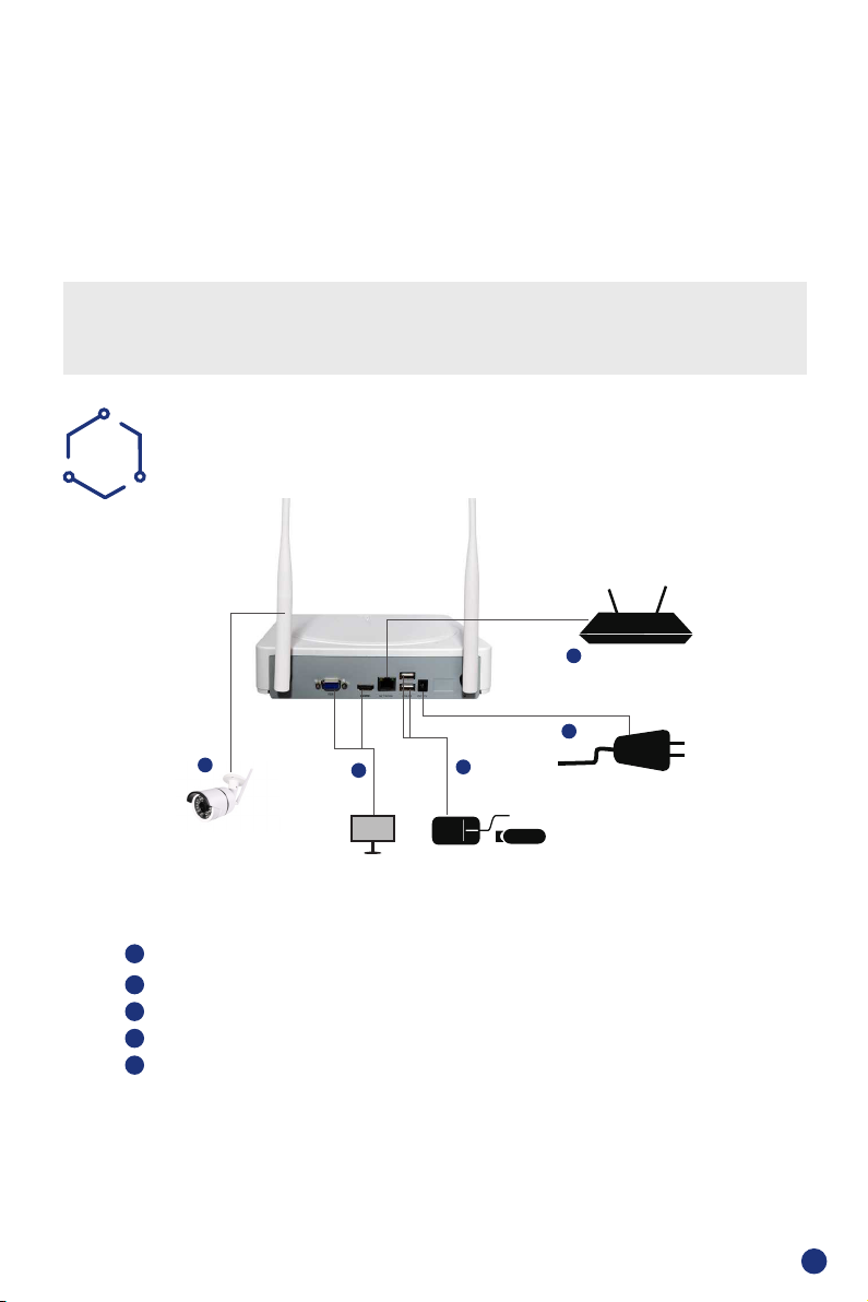
IMPORTANT! This instruction guides you how to install surveillance system.
What accessories you need before getting started
1.One monitor or TV,can not be less than 19"
2.One VGA Cable/one HDMI Cable,use any one that monitor supports
3.One surge protector (advisable)
4.Power supplies for the NVR and cameras. Only use approved PSU's from your supplier.
5.Appropriate tools for installation.
Note:
This instruction guide provides basic information on how to install your CCTV system.
A
Install Your System
1
Camera
1
Connect the WiFi Camera with Power.
2
Connect Monitor to the WiFi NVR with HDMI, or VGA Port
3
Connect the NVR to Router with an Ethernet cable
4
Plug the Mouse to the USB port
5
Plug NVR to Power
2
Monitor/TV
(VGA/HDMI)
4
Mouse & USB
BACK UP
Router
3
5
Power Port
In a few seconds, you can see the Wizard Setting.
Then set password to login the system . (Password must be at least 6
characters)
1
Page 3
SETTINGS
B
Before turning on your NVR, ensure that all connections are correctly installed.
POWER ON AND LOGIN
Connect the NVR with the power supply to start-up.
The light labelled POWER on the front bezel will illuminate.
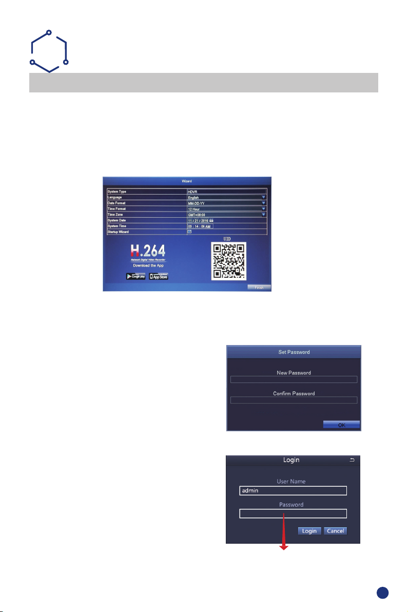
After the NVR start-up, a Wizard Setting panel displays to choose your required settings, including
language, date format, time format, time zone, system date & system time as shown below.
NB: The Wizard Settings menu will automatically display after restarting the NVR, This can be disabled
by removing the tick √.
Please download the App called ADCloud from Google Play or the App Store. The UID (User ID) is the
cloud ID number, which is used to connect your DVR with the internet via your router, to remotely view
your CCTV cameras via the app. For more details please read the REMOTE SURVEILLANCE GUIDE
on page 6.
WIZARD
First Time Login
After exiting Wizard Settings,Set Password dialogue box
is presented.
Enter password, minimum of 6 characters and
re-enter to con rm. After the password is set,
the login box is presented.
Login
After exiting Wizard Settings, login to the DVR.
Double click the screen,(left-click on Mouse) and the Login
dialogue box is presented.
The default User Name is “admin”
Enter password
2
Page 4
CHANGING DISPLAY RESOLUTION
Optimize the NVR Video output to match the monitor output, using the following steps:
NB: Make sure the monitor supports the same resolution as your NVR output resolution,
otherwise the monitor will be unable to display the video.
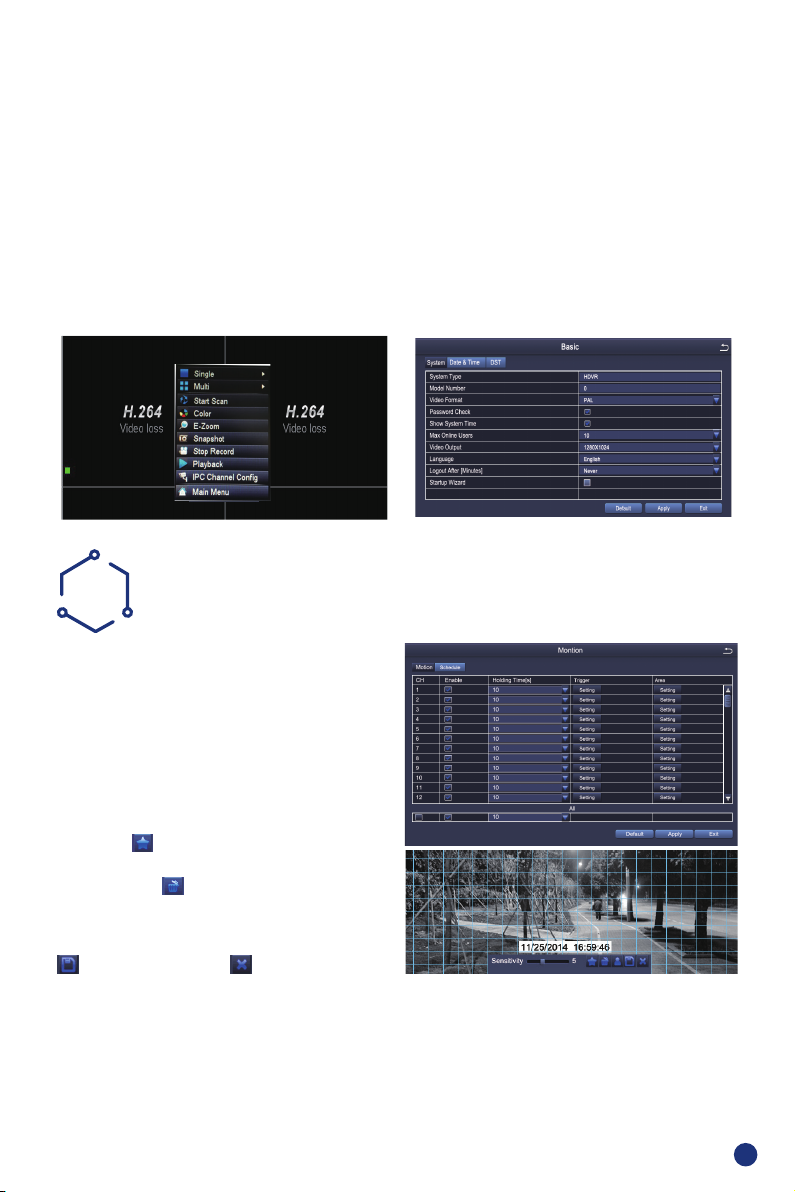
STEP 1. Right click mouse for quick shortcut menu and select Main Menu
STEP 2. Click Setup, then choose Basic menu
STEP 3. Select the desired Video Output resolution
STEP 4. Click Apply to save the settings
STEP 5. Click Exit to restart system, and then Login
NB: The default value is 1024 x 768 so choose the max output resolution your monitor supports, to
view the best resolution
C
Select Camera. Tick the Camera Channel you want
to record on motion detection.
Holding Time. Set recording time length after
motion stops.
Trigger. Multiple channels can be set to record
when motion is detected by one of cameras. For
example, when camera 1 detects motion,camera 2
and camera 3 can be triggered to record as well.
Area. It is possible to set the sensitivity area of
camera viewing range.
Click STAR
as sensitivity area;
Click Trash Box
Click and drag mouse to draw or erase the sensitive
area.
As color and luminance are important for sensitivity, it is necessary to adjust its value under speci c
conditions.
The default value is 4 while value range is from 1 to 8.
Right click the mouse to show or hide the control menu at the bottom of the screen.
Test the setting by moving something or ask someone to walk through the grid area within the camera view
range. If the DVR detects movement within the grid area, a yellow gure would be presented in the screen.
The grid should not cover fl ags, trees or other movable objects to avoid any false alerts.
MOTION
to make the whole viewing range
to remove areas;
Click to save setting Click to exit
3
Page 5
D
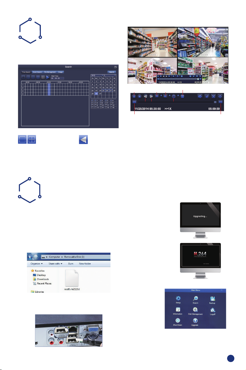
PLAYBACK
Go to system Main Menu--Search, view the
following screen.
Select the channel Start playing
Search recorded video by time or event, then replay.
E
Ask for upgrading software from manufacturer or
the local distributors before operation.
If the NVR requires a software upgrade contact
your supplier. You will be sent the upgrade les by
e-mail.
STEP 1 Put software into U-Disk, and ensure
software is at root directory as below
UPGRADE
Previous
frame
Fast
Forward
Next frame
Play/Pause
Previous Record Next Record
Previous Record: Move to last recorded event
Next Record: Move to next recorded event
Fast Forward: video can be played at different speeds,
from x1, x4 to x16 speed.
Rewind: Video can rewind at x1, x8, x16 & x32 speed.
Screen Display Mode: Both single-screen and
multi-screen are available. You can choose how many
channels you want to playback at a time. Channels with
no recordings will display a blank screen.
STEP 3 Restart NVR(Power
off and on), it will be
upgraded automatically.
Please wait for 3-5 minutes
until NVR interface presents.
Rewind
Multi-screen display
Single-screen
display
STEP 2 Put U-Disk into NVR port USB2.0. and
unplug the mouse from USB port
Note: If upgrade
rmware is available
in server, you can click
Upgrade to update the
system.
Right click mouse – Main Menu - Upgrade
4
Page 6
F
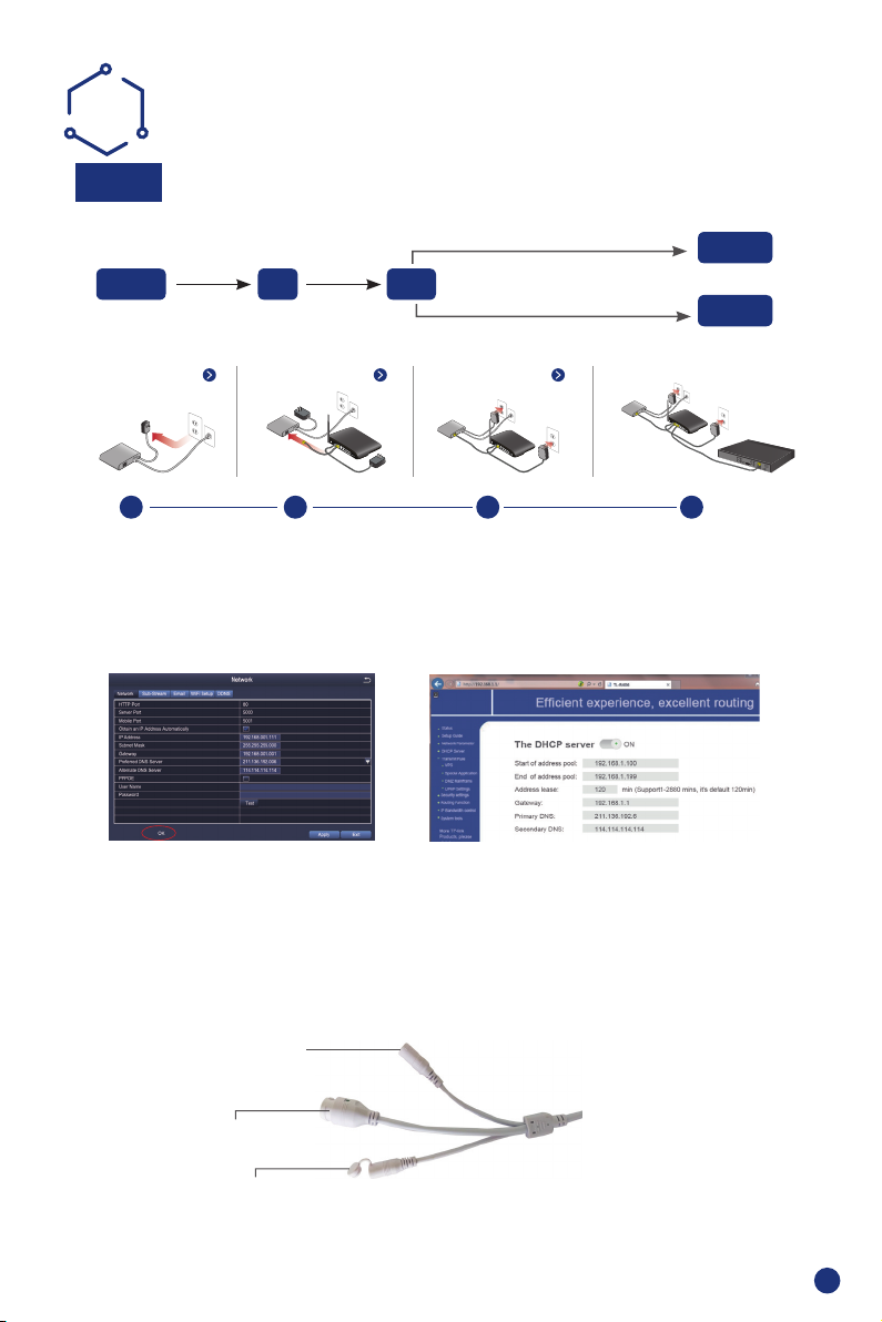
REMOTE SURVEILLANCE
GUIDE
Step 1.
Connect NVR to Enternet
A: How to connect NVR to LAN ?
RJ45 Cable
Fibre Optic DSL
Unplug modem then connect router and device
DSL/CABLE
MODEM
DSL/CABLE
modem
ROUTER
Router
DSL/CABLE
modem
ROUTER
WiFi or RJ45 Cable
1 2 3 4
B: How to test your NVR's network ?
(1) Right click Mouse > Go to Main Menu > Setup > Network
(2) Tick 'Obtain IP address automatically'
(3) Click 'Test', if 'OK' is displayed, the network is connected successfully.
Note: Please ensure DHCP in your router is open.
DSL/CABLE
modem
ROUTER
NVR
PC
NVR
Note: If you buy the wireless camera and NVR in a package,the WiFi camera is added to the NVR by
default, you can see video when power on.
If you buy wireless Camera and NVR seperately,then you need to add the device by manual, do it as
following steps.
1). Press and hold the reset button for 10s, and restore the WiFi camera to the factory settings, as
shown in Figure 1.
Power Port
RJ45 Port
Reset Button
Figure 1
5
Page 7
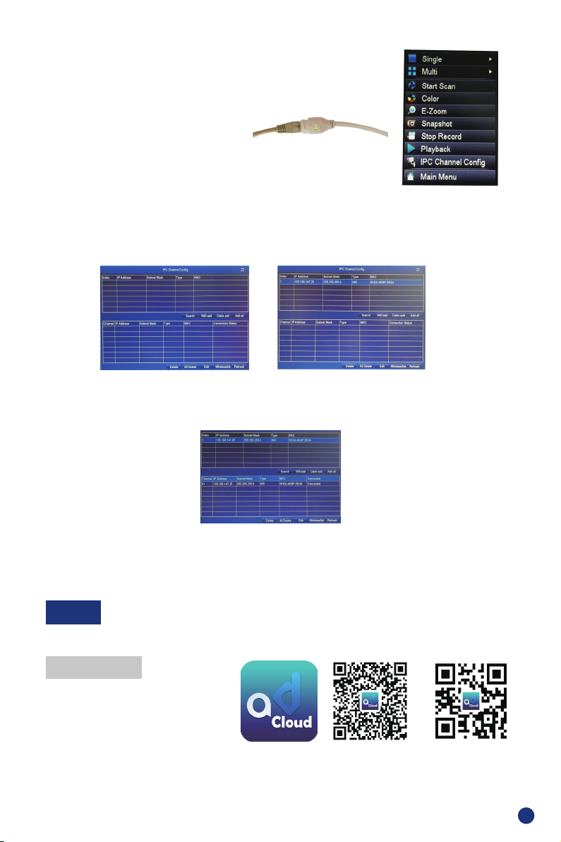
2). Enter the NVR menu interface to restore it
to the factory settings;
Main Menu-Setup-Advanced-Reset.
3).Connect the NVR and WiFi camera by RJ-
45 cable, as shown in gure 2.
4).Enter the NVR interface, right click the
mouse, select “IPC Channel Con g”, as
shown in gure 3.
5).Click “search”, WiFi camera IP address is displayed, then click “WiFi add” to add the camera to NVR
system, as shown in Figure 4 and Figure 5.
Figure 4 Figure 5
6).Wait for a few seconds,camera would be added to NVR channel sucessfully, as shown in Figure 6.
Figure 2
Figure 3
Figure 6
7).Unplug RJ-45 cable from the added camera, and connect it to another WiFi camera, then do it as step
3 to step 6 as above.
Step 2.
Remote Monitoring Setting
A: Smartphone Remote Monitoring
Download App
Scan the QR Code or search ADCloud(in
App store or Google play) to download
the free app,then install in your mobile
phone.
iOS ADCloud android
6
Page 8
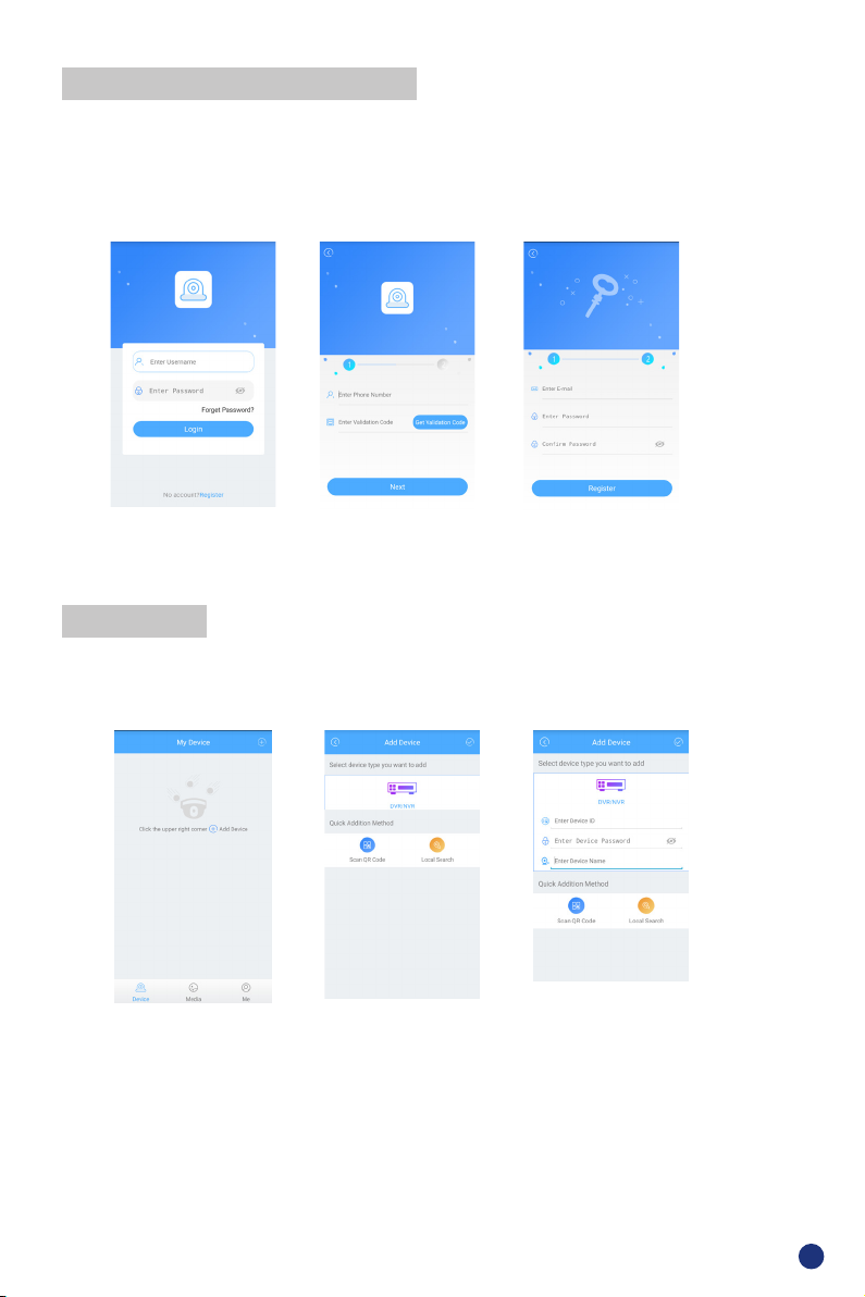
Personal Account Registration
● Start the mobile app ADCloud
● Click “Register ” in the bottom of interface
● Input your mobile phone number to get validation code,click Next to input email box,
password,then save it.
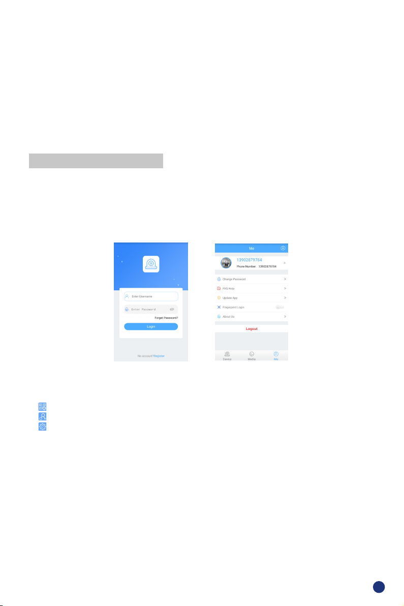
Login Interface
Note: Email box is used to retrive password when it is forgotten.
Registration
Login Password Setting
Add Device
Login the app,get into the main interface(My Device),click”+”in the upper right corner,three
different options of device addition are available.
My Device
1.Manual Addition
● Choose device type
● Input Device ID by manual
● Input Password(Same as DVR system login),device name
● Click √ to save
Select Addition Method
Device Addition
7
Page 9
2.QR Code Scanning
● Find UID QR Code(in DVR label and DVR system)
● Click Scan QR Code to get the Device ID
● Input Password(Same as DVR system login),Device Name
● Click √ to save
3.Local Search
● Turn on mobile phone WiFi setting,make it connect with the same LAN as DVR’s
● Click Local Seach,Device ID will be displayed in a few seconds
● Choose the intended ID to add
● Input password(Same as DVR system login),Device name
● Click √ to save
App Function Introduction
1.App introduction
● Forget Password: Click to retrive password
● Change password: change app login password
● Update Loading: update your app to the latest version
● Fingerprint login: no need to input password if ngerprint touch function is available in your phone
My InformationLogin Interface
2.Device Information
● UID QR Code of the device
● Select channel to preview
● Change password,turn on Alarm Push Notication and remove device
● Video: Click to start recording or stop recording
● Screen Shot: Click to catch photo
● Event Playback: to see the motion detection video and remote video in DVR storage(All time)
● SD/HD: change video resolution(Standard Denition,High Denition)
● Intercom: 2-Way talk if device support(current device does not support this function)
8
Page 10
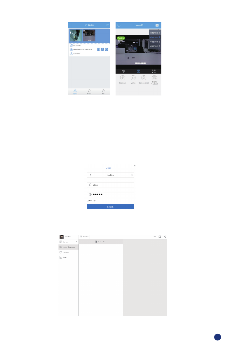
Video PreviewDevice Information
B: PC Client Remote Monitoring
The PC Client AVSS is applied for DVR,NVR,IPC, with functions live view, Device management,
remote video playback,etc. Ask for AVSS from the local distributor or download it from the link www.
nsst.com (If available).
1.Login
Install the PC Client,double click the icon AVSS to open, choose language and click to Login.
Note: use the default user name and passpword, or enter the same login information as your mobile
App.
2. Device Management
Click Device Management to Add Area and device.
9
Page 11
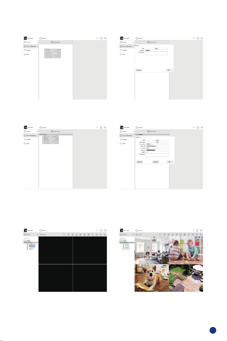
Add Area. Right Click mouse in the blank to add area and enter area name. Area name is used to
describe the monitored place.
Add Device. Right Click Mouse on Area name to add device, change the device type, enter device
name, device ID, user name, device password and channel number, then click OK to save.
3. Preview
Click preview to nd device list, right click device to Play All and Stop All, preview video can be
displayed or stopped.
10
Page 12
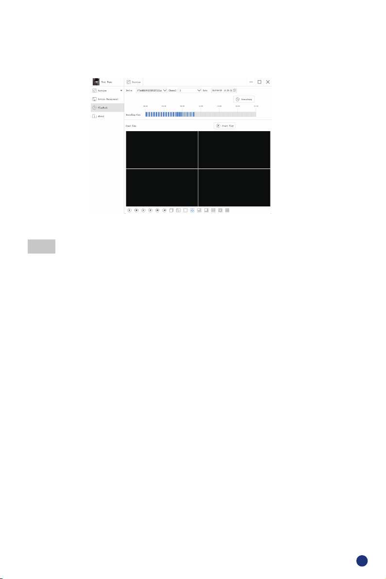
4. Playback
Click Playback, select the Device ID, Channel number, Date, then Searching to nd the video,
double click the Recording Time to x the exact time, then click Start Play.
FAQ:
1).Q: Why failed to search the device when adding ?
A:Make sure the device and mobile are in the same local area network,otherwise Enter Device ID
by manual
2).Q:Why the device is offl ine ?
A:Please check
● If device has been connected to Internet
● If Router working ne
● If DHCP server of Router turned on or not
3).Q:Why unable to nd out recording le
A:Please check
● If HDD is broken
● If searching period is valid
● If device system time is correct
11
Page 13

FCC Warning Statement
Changes or modifications not e xpressly approved by the party responsible for compliance could void the user’s authority to
operate t he equipment. T his e quipment has been tested and found t o comply w ith the limits for a Class B d igital device,
pursuant to Part 15 of the FCC Rules. These limits are designed to provide reasonable protection against harmful interference
in a residential installation. T his equipment generat es uses and can radiate radio frequency energy and, if not installed and
used in accordance w ith t he instructions, may cause harmful interference to radio c ommunications. However, there is no
guarantee that interference will not occur in a particular installation. If this equipment does cause harmful interference to radio
or television reception, which can be determined by turning the equipment off and on, the user is encouraged to try to correct
the interference by one or more of the follow ing measures:
‐‐ Reorient or relocate the receiving antenna.
‐‐ Increase the separation between the equipment and receiver.
‐‐ Connect the equipment into an outlet on a circuit different from that to which the receiver is connected.
‐‐ Consult the dealer or an experienced radio/TV technician for help.
FCC Radiation Exposure Statement
The antennas used for this transmit ter must be installed to provide a separation distance of at least 20 cm from all persons and
must not be co‐located for operating in conjunction with any other antenna or transmitter.
 Loading...