

Page 1

7” TFT WIRELESS PROFESSIONAL WEATHER STATION & PHOTO ALBUM Owner’s Manual
Thank you for purchasing the new generation of 7” TFT weather station & photo album. Designed and engineered with the
state-of-art technology and components, this instrument will provide accurate and reliable measurement of weather forecast,
wind speed/direction, rainfall and indoor/outdoor temperature/humidity as well as a digital photo album. Read this manual
carefully to fully explore the features and functions of the new product.
The package includes
- Photo Frame (Main unit)
- Infrared (IR) remote control
- Wind meter (built-in thermo-hygrometer)
- Rain gauge
- Adapter
Additional tools needed for installation
- Small Phillips screwdriver
- Hexagonal Key
- Electric drill
- Pencil
- Level
- Mast, 1 – 1.25 inch (2.54 – 3.18 cm) in diameter (to mount the anemometer)
Buttons on the photo frame Press Functions
POWER Turn on or off the unit
UP/DOWN Move up or down in the setup mode
LEFT/RIGHT Select photos or move left or right in the SETUP mode
Enter Enter the display mode or confirm setting in setup mode
Exit Exit the current display mode
(When display is off, press any buttons except [POWER] to turn on the weather display mode for around 1 minute)
Buttons on the IR remote control Press Functions
POWER Turn on or off the unit
PHOTOS Enter photo mode
WEATHER Enter weather mode
WEATHER + PHOTOS Enter weather & photo mode
CALENDAR Enter calendar mode
SETUP Enter setup mode
SLIDESHOW Enable or disable slideshow function (only available in photo mode)
MENU Enter menu mode
ENTER Enter the display mode or confirm setting in setup mode
Exit Exit the current display mode
UP/DOWN Move up or down in the setup mode
LEFT/RIGHT Select photos or move left or right in the display mode
ZOOM Zoom in the photo
ROTATE Rotate the photo
(When display is off, Press any buttons except [POWER] on the remote control to turn on display for around 1 minute)
Page 2
INTITIAL SETUP
BATTERY & ADAPTER INSTALLATION
Photo Frame
Main Power Source: Plug in the 5.0V adapter into the adapter socket on the right for basic operation
IR Remote Control
Battery (CR2025) is included in the IR remote control. For initial setup, pull out the battery insulation sheet from the bottom of
the IR remote control.
To replace the battery, follow the instruction on the back of the IR remote control to pull out the battery door. Follow the battery
polarity and replace a new CR2025 battery. Close the battery door.
:
Installation
The weather station operates at 915MHz and does not require wire installation among the component parts. To ensure
successful installation and the best performance, we recommend you follow the installation instructions in the order they
appear in this manual.
1. Selecting a location for the anemometer
Select a mounting location for the anemometer that is:
- Outdoors, not blocked on top or sides, so wind can freely reach the anemomete r
- Within 75 meter open area from the monitor. Reduce distance if obstacles is between the anemometer & the monitor
The best location for the anemometer is usually mounted on a mast in an open area where wind is not blocked on top or sides,
or above roof level on the building where the monitor is located.
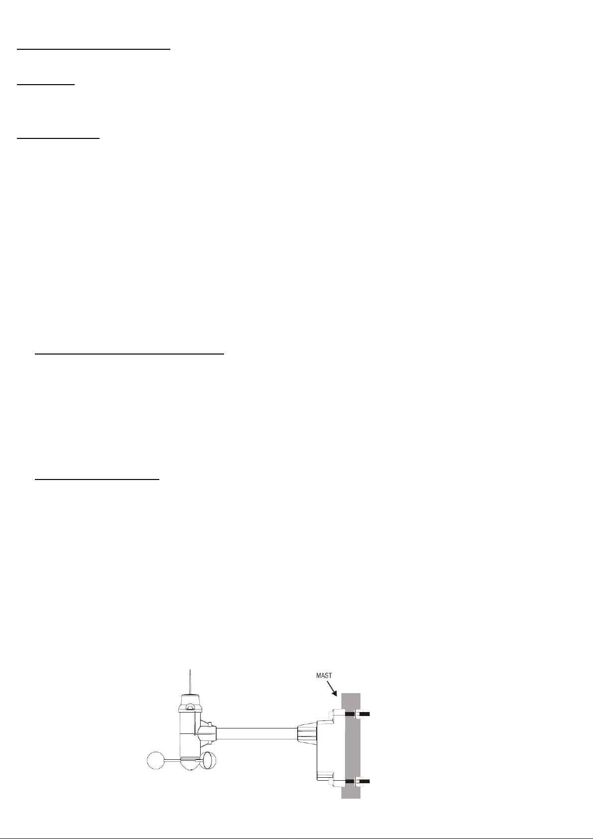
2. Mounting the anemometer
Important: Before mounting, be sure the monitor & anemometer are within the effective transmission range.
Note: To mount the anemometer, you need a mast (not supplied) about 1 – 1.25 inches (2.54 – 3.1 cm) in diameter, and the
hardware necessary to fasten it to the mounting location. If you previously installed such a mast (for mounting anten na, for
example), you can mount the anemometer on that mast.
1. If necessary, mount and ground a mast as directed in the instructions provided by the mast.
2. Place the supplied U-shape metal plates around the mast. Insert 4 pieces of the supplied Hex screws through the hole s
of the U-shape plates and the holes on the anemometer’s mounting bracket.
(The wind vane is above the wind cup and the metal bar of the anemometer is i n horizontal level)
3. Tighten the supplied Hex nut onto both ends of each screw
Page 3
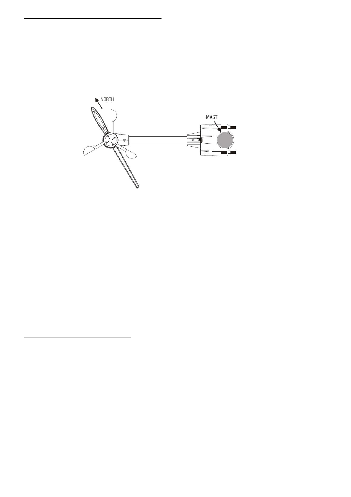
4. Calibrating the anemometer & installing batteries
After mounting the anemometer, follow these steps to calibrate the wind direction so that the anemometer properly measures
the wind direction and transmit to the monitor. Be sure battery has been removed from the anemometer before the calibration.
Important: The same calibration is needed for the first set up and every battery replacement.
1. After mounting the anemometer, loosen the screws on the battery door with a small screwdriver and open the battery door.
2. Use the compass on the anemometer and turn the wi nd vane so it is pointing due north.
3. Hold the wind vane pointing due north and do not allow it to turn. Insert 2 pieces of AA batteries according to the polarity
indicated. The red LED indicator above the battery cover of the anemometer will flash few times right after battery
installation. Be sure the vane is pointing due north at the moment when red LED flashes a nd the calibration is now
completed. Replace the battery cover and tighten the screws.
4. If the wind vane is not pointing due north when the red LED first flashes, remove batteries and repeat step 2 & 3.
5. Go to “SET UP” mode, select “SEARCH NOW” in the “WIRELESS SENSOR RECEPTION” section and exit. Wind direction,
wind speed, wind chill & channel-1 temperature/humidity readings will appear within 2 minutes if the RF transmission is
successful.
6. If the wind reading does not appear after 2 minutes of searching, the RF tran smission is failed.
Shorten the distance between the monitor & wind meter and search for the sensor again. If the RF transmission still failed,
then shorten the distance again and reset the wind meter by removing all batteries from the wind meter and wait for 10
seconds before re-installing the batteries again. Then repeat above step until the RF communication is completed.
5. Selecting a location for the rain gauge
Select a mounting location for the rain gauge that is:
- a flat, level surface and suggest to look for a location where the rain gauge can be placed 1 meter or more above ground
level.
- within 40 meter (131 feet) open area from the monitor. Reduce distance if obstacles is between the rain gauge & the
monitor
- in an area not blocked on the top or sides, so rain can freely reach the rain gauge (for example, not under an overhang or
too close to a building or fence)
Cautions:
- To prevent false rainfall readings caused by water splashes, do not choose a location that is not level or that is too close
to the ground, a swimming pool, lawn sprinklers, or anywhere water might accumulate or run off
- The screen in the cylinder of the rain gauge filters most debris (such as leaves) that might fall into the rain gauge. To
avoid frequent build-up of debris in the cylinder, do not mount the rain gauge too close to the trees or plants
Page 4

6. Battery Installation for the rain gauge
1. Press the tabs back as indicated below to unlock the rain gauge cover
2. Lift the rain gauge cover off its base. Then carefully remove the packing tape from the bucket assembly
3. Open battery cover and insert 2 pieces of AA batteries according to the polarity indicated. Close the battery cover
4. Replace & lock the rain gauge cover on the base
5. Go to “SETUP” mode, select “SEARCH NOW” in the “WIRELESS SENSOR RECEPTION” section and exit. The monitor is
now searching for all remote sensors. Total rainfall reading (in this case “0” mm or inch) will appear within 2 minutes if the
RF transmission is successful and the monitor & rain gauge are now within the effective transmission range.
6. If the rainfall reading remain “- - -“ after 2 minutes of searching, the RF transmi ssion is failed.
Shorten the distance between the monitor & rain gauge and search for the sensor again. If the RF transmission still failed,
then shorten the distance again and reset the rain gauge by removing all batteries from the rain gauge and wait for 10
seconds before re-installing the batteries again. Repeat step 5 (& 6) until the RF communication is completed.
7. Mounting the rain gauge
Before mounting the rain gauge, be sure the rain gauge & monitor are within the transmission effective range and batteries are
installed.
1. Hold the base of the rain gauge flat against the mounting surface then use a level to make sure the rain gauge (as it rest
on the mounting surface) is horizontally level.
2. Use a pencil to trace the inside of the mounting holes on the base of the rain gauge to mark the screw locations.
3. Drill a hole in the center of each marked location and insert the supplied plastic screw plugs
4. Hold the rain gauge against the mounting surface so the holes on the base are aligned with the plugs, then thread the
supplied washer head screws into each hole and use a screwdriver to tighten them.
WEATHER FORECAST SETTING
To obtain an accurate weather forecast, you need to input your current weather condition as initial setting.
Go to “SETUP” display mode and use [UP]/[DOWN] to select “Weather Forecast”. Press [LEFT]/[RIGHT] to select your current
weather condition between “Sunny”, “Partly Cloudy”, “Cloudy”, “Rainy” or “Stormy” as the initial weather forecast setting. Press
[ENTER] to confirm setting and [EXIT] to exit the “SETUP” mode.
The unit predicts weather condition of the next 12 – 24 hours based on the chan ge of atmospheric pressure. The coverage
area is around 30 – 50 km. The weather forecast is based on atmospheric p re ssu re change and is about 70-75% correct. As
weather conditions cannot be 100% correctly forecasted, we cannot be responsible for any loss caused by an incorrect
forecast.
Page 5

SUNNY PARTLY CLOUDY CLOUDY RAINY STORMY
NOTE:
Different geographical location such as inland area or coastal region has different weather forecasting response. In case your
weather forecast always show the wrong weather forecast over a long period of time and does not reflect the actual weather
condition, it is necessary to adjust the weather forecast to the current weather condition with the above setting procedure.
OPERATION
There are 5 display modes in the menu selection.
PHOTO WEATHER WEATHER & PHOTO CALENDAR SETUP
Press [LEFT] or [RIGHT] to select and [ENTER] to enter the selected display mode.
PHOTO MODE
Save your photos (JPEG format) into your memory device (USB memory stick, SD or MMC card) and insert into the connector
on the side of the photo frame when the unit is off. Turn on the photo frame and enter PHOTO mode to view the photos.
Press [LEFT] / [RIGHT] to view the next or previous photo
Press [SLIDESHOW] to enable or disable the slideshow
Press [ZOOM IN] to enlarge the photo (press repeatedly to resume to the original photo size)
Press [ROTATE] to rotate the photo
To set the time interval & transition effect of the slideshow, enter th e SETUP mode for setting.
WEATHER MODE
Page 6

1) Weather forecast – includes sunny, p artly cloudy, cloudy, rainy & stormy
2) Pressure bar chart – shows pressure level & trend of the past 6 hours
3) Barometric pressure - pressure reading (refer SETUP mode for pressure unit setting)
4) Pressure trend – rising, steady or falling
5) Daily, weekly or monthly rainfall in inch or mm
6) Total Rainfall in inch or mm
7) Wind chill in degree F or C
8) Average wind speed in m/s, knots, mph & km/h
9) 16 resolution of average wind direction
10) Gust wind speed in m/s, knots, mph & km/h
11) Outdoor or indoor temperature in degree C or F (with trend – ri sing, steady or falling)
12) Outdoor or indoor humidity (with trend – rising, steady or falling)
13) RF signal indicator – flashes when it is searching for RF signal from remote sen so r; stays on when it has successfully
received RF signal from the remote sensor
14) Clock – displays in 24 or 12 hour format (refer “Time format” in SETUP mode for setting)
15) Alarm icon – appears when alarm is enabled
16) Moon phase with stars icons – New moon (the moon icon disappears), Waxing Crescent moon, First Quarter Moon,
Waxing gibbous moon, Full Moon, Waning gibbous Moon, Last Quarter Moon & Waning Crescent Moon
17) Calendar – displays in Day/Month or Month/Day format (Refer SETUP mode for setting)
18) Channel number of outdoor remote sensor – channel 1, 2 or 3 (Default channel 1 for wind meter)
WEATHER & PHOTO MODE
1) Clock – displays in 24 or 12 hour format (refer “Time format” in SETUP mode for setting)
2) Alarm icon – appears when alarm is enabled
3) Weather forecast – includes sunny, p artly cloudy, cloudy, rainy & stormy
4) Daily, weekly & monthly rainfall in inch or mm
5) Average wind speed and wind direction
6) Indoor or outdoor temperature in degree C or F (with trend – rising, steady or falling)
7) Indoor or outdoor humidity (with trend – rising, steady or falling)
8) RF signal indicator – flashes when it is searching for RF signal from remote sensor; stays on when it has successfully
received RF signal from the remote sensor
9) Photo
Page 7

CALENDAR MODE
Press [LEFT] / [RIGHT] to show the calendar of the previous or next month
Press [UP] / [DOWN] to show the calendar of the previous or next year
To set the calendar, ente r SETUP mode for setting
SETUP MODE
Press [UP]/[DOWN] to move to your setting item. Press [LEFT]/[RIGHT] to select the setting and press [ENTER] to confirm the
setting.
Language: Select between English, Dutch & French
Slideshow Time: Select between 3s, 5s, 15s, 1 min, 15 min & 1 hour for photo slideshow mode
Transition Effect: Select the transition effect of the photo slideshow mode
Photo repeat mode: Select between random, manual or repeat all for the photo slideshow mode
Display mode: Select the photo display mode (cinema, stretch, crop)
On/Off Timer 1 - On: Adjust the first automatic power on time in HH:MM; enable or disable
On/Off Timer 1 - Off: Adjust the first automatic power off time in HH:MM; enable or disable
On/Off Timer 2 - On: Adjust the second automatic power on time in HH:MM; enable or disable
On/Off Timer 2 - Off: Adjust the second automatic power off time in HH:MM; enable or disabl e
(For power saving, you can select when to turn on or off the photo frame
automatically throughout the day using the On/Off timer 1 or 2)
Brightness: Select the brightness of the display from level 1 to 16
Contrast: Select the contrast of the display from level 1 to 16
Saturation: Select the saturation of the display from level 1 to 16
Radio-Controlled Reception: (This function is not available for this unit. Please keep this setting to “Off”)
Automatic - search for radio-controlled daily at around 2:03am
Search now - start searching for radio-controlled clock signal
Off – turn off the daily radio-controlled clock reception
Time Zone: Adjust the clock to your local time using the time offset setting
Time/Date: Adjust the calendar and time
Calendar Display Format: Select between Day/Month or Month/Day format
Time Format: Select between 24 & 12 hour format
Alarm: Adjust the alarm time and enable/disable the alarm
Wireless Sensor Reception: Automatic – default RF reception mode
Search now – Search for remote sensor immediately
Temperature Unit: Select between degree C & F for temperature
Weather Forecast: Select between sunny, partly cloudy, cloudy, rainy & stormy
Rainfall unit: Select between mm & inch
Wind unit: Select between m/s, knots, mph & km/h
Sea Level Pressure: Adjust the sea level pressure for your local area
Pressure Unit: Select pressure unit between hPa, mmHg, inHg & mb
Remote Channel Display: Automatic – Show the channel(s) being registered
Channel 1 only – Shows only channel 1 reading only
Channel 2 only – Shows only channel 2 reading only
Channel 3 only – Shows only channel 3 reading only
Page 8

Clear All Rai nfall Record Now: Yes / No
Default Setting: Yes / No
S/W Version: Software version
TROUBLE SHOOTING
- In case of power outage, the unit will shut off completely and the synchronization of RF remote sensor will be lost. You
are required to set up the remote sensor & weather forecast again following the procedures in the manual.
- After every battery replacement of the remote sensor, you are required to follow the procedure in the manual to setup the
remote sensor again.
- The USB port on the side of the photo frame should not be used as a power source or charger to provide power to your
USB device other than a USB flash drive. The extra power provided may affect the reception & performance of the photo
frame and may reset the unit. We are not responsible for any damage to the photo frame due to this reas on.
- If your photo frame does not receive RF temperature & humidity signal from the remote sensor, check the battery level of
the remote sensor . Replace the batteries of the remote sensor when the “
“ low battery icon appears on the sensor’s
display and repeat the setup procedure in the manual. If it continues to fail, try to shorten the distance between the photo
frame & remote sensor and repeat the setup procedure in the manual to link up the sensor. Obstacle or wall between the
remote sensor & photo frame will shorten the effective reception range of the unit. Do not place the photo frame & remote
sensor near metal or electrical appliances such as TV, computer or WiFi system due to the RF interferen ce emitted from
these devices. Avoid placing the remote sensor in direct sunlight as it will heat up the sensor and provide inaccurate
outdoor temperature reading. In cold weather below 0 C, the battery voltage level of the remote sensor will drop and the
overall transmission range will reduce and this is normal. Shorten the distance between the sensor & the photo frame.
For extreme low outdoor temperature below 0C, you are advised to use lithium AAA battery on the remote sensor as
normal alkaline battery may freeze at extreme low temperature.
- If your weather forecast reading does not reflect the actual weather condition for a long period of time, you are require d to
adjust the weather forecast setting in the SETUP mode as described in the manu al.
- If the IR remote control does not function even at a short distance in front of the photo frame, the battery inside the IR
remote control may be flat. Replace a new CR2025 battery following the battery polarity indicated on the back of the IR
remote control.
BA TTERY DISPOSAL
Replace only with the same or equivalent type recommended by the manufacturer. Please disposal of old, defective batteries
in an environmentally friendly manner in accordance with the relevant legislation.
SPECIFICATIONS
Memory : Supports USB flash drive (up to 32GB), SD & MMC cards (up to 32GB)
Photo format : Supports Jpeg format
Indoor Temperature : 0 C to + 50 C (+32 F to +122 F)
(Shows LL when below 0C or 32F; shows HH when above 50C or 122F)
Outdoor Temperature : -20 C to +60 C (-4 F to +140 F)
(Shows LL when below -20C or -4F; shows HH when above 60C or 140F)
In/Out Humidity : 20% - 99% RH
RF Frequency : 915MHz
Transmission : Wind meter – up to 75 meter (246 feet) in open area
Rain gauge – up to 40 meter (131 feet) in open area
Resolution : 0.1 degree C for temperature, 1% for humidity
Wind speed range : 0 – 30m/s
Page 9

: 0 – 108 km/h
: 0 – 67 mph
: 0 – 58.3 knot
Rain Gauge reading : 0 – 9999 mm
: 0 – 393.66 inch
Power : 5.0V adapter for photo frame
: AA x 2 pcs for wind meter
: AA x 2 pcs for rain gauge
: CR2025 x 1 pc for IR remote control
NOTE: THE MANUFACTURER IS NOT RESPONSIBLE FOR ANY RADIO OR TV INTERFERENCE CAUSED
BY UNAUTHORIZED MODIFICATIONS TO THIS EQUIPMENT. SUCH MODIFICATIONS COULD
VOID THE USER AUTHORITY TO OPERATE THE EQUIPMENT
This device complies with part 15 of the FCC Rules. Operation is subject to the following two conditions: (1) this
device may not cause harmful interference, and (2) this device must accept any interferenc e received, including
interference that may cause undesired operation.
NOTE: This equipment has been tested and found to comply with the limits for a Class B digital devi ce, pursuant to
Part 15 of the FCC Rules. These limits are designed to provide reasonable protection against harmful interferen ce in a
residential installation. This equipment generates, uses and can radiate radio frequency energy and, if not installed
and used in accordance with the instructions, may cause harmful interference to radio communications. Ho wev er,
there is no guarantee that interference will not occur in a particular installation.If this equipment does cause harm ful
interference to radio or television reception, which can be determined by turning the equipment off and on, the user is
encouraged to try to correct the interference by one or more of the following measures:
-- Reorient or relocate the receiving antenna.
-- Increase the separation between the equipment and receiver.
-- Connect the equipment into an outlet on a circuit different from that to which the receiv er is connected.
-- Consult the dealer or an experienced radio/TV technician for help.
 Loading...