

Page 1
CONTENTS:
4) GX-4 New Features
• New Front-End Pneumatic Kit
• New Adjustable Drop Forward
Assembly
• New Swing Trigger System
• Packaged Barrel
2) Maintenance
General Notes
3) Installation
X-2 Inline Regulator
4) Adjustments
• X2 Inline Regulator
• Jack Hammer II
Front Pneumatic Regulator
• 3-Way Shaft
• Sear Lug
USER MANUAL
©2003 ANS Xtreme Performance
ANS Xtreme Performance
3885 Cochran Unit R
Simi Valley, CA 93063
phone: (805) 527-5661
fax: (805) 527-2490
email: [email protected]
www.ansxtreme.com
www.ansusergroup.com
GX-3 / GX-4
Page 2
INSTALLATION STEPS:
1. Identify the four ports on the inline
regulator:
• 2 are labeled for input pressure.
• 1 is labeled for output pressure.
• 1 is the burst disc.
2. Installing the inline regulator into the
marker body. Screw the regulator into the
vertical ASA of the marker body until it
stops. Do not torque.
3. Aligning the inline regulator. Unscrew
the regulator until one of the pressure input
ports faces the rear of the marker and the
pressure output port is to one side of the
marker. This will allow the micro gauge to be
installed without interfering with the trigger
guard. The exact position of the pressure
output port can vary according to your
preference, i.e. the gauge is facing the front
and the line set up comes out the side.
IMPORTANT: The regulator can be loosened
almost 1-1/2 turns and still retain a perfect
seal. It may move loosely and will appear to
leak but as the system is pressurized the
regulator will get ridged. In fact, 90% of the
time most regulators are kept slightly loose
or “backed off” to allow the input to be in the
preferred spot.
4. Plugging the input pressure port. Two
pressure input ports are provided so that
the location of the gauge can be adjusted to
your liking. One pressure input port will be
connected to the propellant line and the
other will be plugged.
• Locate the 1/8" pipe plug and coat the
threads lightly with red 262 Loctite.
• Screw the pipe plug into ONE of the
input pressure ports on the regulator.
To maintain a good seal have the plug
go flush with the regulator body.
5. Installing the micro pressure gauge. The
micro-gauge indicates the pressure
coming out of the regulator and is useful to
determine optimal performance of the marker.
• Lightly coat the threads of the gauge with
red 262 Loctite.
• Install the micro-gauge into the Output
Pressure orifice and tighten snug using a
Crescent wrench.
It is recommended that the micro-gauge be
used, but it is not essential. If the microgauge is NOT installed, the pressure output
port must be plugged as follows:
• Locate a 1/8" pipe plug (supplied) and
coat lightly with red 262 Loctite.
• Screw the pipe plug into the output
pressure port and tighten snug.
6. Installing the propellant feed line.
• Whether you will be using a macro line
fitting or nickel-plated connectors, the
threads should be coated lightly with red
262 Loctite.
• Screw the propellant feed line into the
last available open input pressure orifice.
X-2 Inline regulator installation is now
complete. Proceed to the Adjustments section for
calibration instructions.
Adjustments
X-2 Inline Regulator Adjustment
On the GX-3, this part is not calibrated
from the factory and requires adjustment when
installed. Unlike conventional cockers that
adjust velocity through the back of the marker,
GX series markers require adjustments through
the Quick Twist knob on the bottom of the
regulator, NOT through the Internal Velocity
Gauge (IVG). The IVG should not be adjusted
on this marker.
YOU’LL NEED:
3/16" Allen wrench and/or crescent wrench
ADJUSTMENT STEPS:
1. Locate the Quick Twist adjuster knob at the
bottom of the inline regulator.
2. Loosen (counterclockwise) the 2 set screws
(or the lock washer on newer models) on
the bottom of the Quick Twist knob about
2 turns.
GX-4 New Features
The GX-4 marker comes with the same
quality engineering and style that you’ve come
to expect from ANS, plus a load of new features
that improve performance, looks, and value.
Maintenance
GX-3 and GX-4
Maintenance Information
GENERAL NOTES
• IMPORTANT: If CO2 is used, it must be
an Anti-siphon tank on both the GX-3 and
GX-4 Cocker.
• Always cock back the marker before installing
a propellant tank.
• GX Cockers are nitrogen-ready; Nitrogen is
the recommended propellant.
• The X-2 Inline Regulator needs to be
installed on the new marker. (GX-3 only)
Installation
X-2 Inline Regulator Installation
On the GX-4, the X-2 Inline Regulator comes
pre-installed and calibrated so that no adjustment
is necessary. For all GX-3 markers, this section
explains how to install the X-2 Inline Regulator.
GX-3 users will then need to calibrate the part
for normal use by following the instructions
under the Adjustments section of this manual.
The Inline Regulator installs vertically in front
of the trigger guard and controls the velocity at
which paintballs exit the marker.
YOU’LL NEED:
• Red 262 Loctite
• 1/8" pipe plug (supplied in X-2 Rebuild Kit)
• Micro pressure gauge (included)
• Large Crescent wrench
• 3/16 Allen wrench
2
ANS Xtreme Performance: GX-3/GX-4 User Manual
ANS
GX-3/GX-4 USER MANUAL
ANS
GX-3/GX-4 USER MANUAL
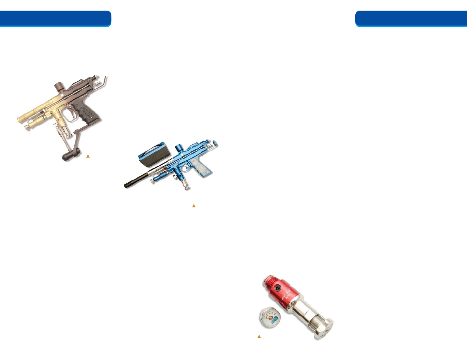
GX-3 Marker
GX-4 Marker
Inline Regulator
ANS Xtreme Performance: GX-3/GX-4 User Manual
3
New Front-End Pneumatic Kit
Front-end pneumatics have been re-engineered
for faster Rate of Fire (ROF).
• The Jack Hammer has extra porting that
improves gas recharge.
• The 3-Way has additional exhaust porting for
faster block return.
New Adjustable
Drop Forward Assembly
The Adjustable Drop Forward with integrated
ASA has:
• Quick disconnect on Drop Forward for easy
disassembly
• Braided stainless steel propellant feed lines
• Convenient on/off twist knob for easy gas
tank activation
New Swing Trigger System
The improved action Double-Finger Swing
Trigger Kit provides:
• Faster ROF and a new level of style
• Greater gas efficiency with improved N-2
Hammer Kit
Packaged Barrel
The GX-4 comes complete with a new 14"
2-piece barrel:
• Ported and vented for improved performance
• Matched to the marker for uniform style
Page 3
barb of the ram. The 3-way plays a major roll in
the proper function of the gun.
YOU’LL NEED:
5/16" open end or needle nose pliers
ADJUSTMENT STEPS:
1. Set the marker in normal operational mode
for firing.
2. Hold the marker in your left hand and focus
on the 3-way. Locate the brass shaft. It is
located in the front of the 3-way and can be
seen through the external vent port. On the
backside of the 3-way you will find the actuator collar, it is hexagonal in shape and has
two sets of holes tapped into the body. The
set in the front is used to lock the 3-way
shaft in with the collar (keep in mind only
one set screw is used, the other port is left
open.) The set in the rear houses the shaved
nylon screws preventing the actuator rod
from rotating out of adjustment.
3. Checking the shaft position. Still holding the
marker in your left hand, place your thumb
on the bend radius of the actuator rod
(directly above the trigger) and push it forward. Note: On the GX-3 the trigger will be
resting in a forward position when this step
is in progress. However on the GX-4 the trigger will need to be depressed. This is due to
the reverse characteristics of the swing
frame. Look inside the front vent port of the
3-Way. Using your thumb, press the bent
radius forward and notice the brass shaft
move as pressure is applied. There is a slight
gap between the trigger plate and the actuator rod. This is the gap we are eliminating by
pushing the rod forward. Your goal is to have
the brass shaft sit flush with the 3-Way body
as the actuator rod is fully extended.
Achieving this will give your marker its best
performance. If the shaft does not sit in a
proper position, it will either create a leak or
slow down the action of the marker.
4. Adjusting the shaft position. Use a 5/16"
open end or needle nose pliers to rotate the
hex collar on the actuator rod so that the
shaft tip and the 3-way body are on the same
plane when the actuator rod is fully extended. Note: Turning the hex collar counterclockwise will lengthen the position of the
shaft. Turning it clockwise will shorten it up.
3-Way Shaft adjustment is now complete.
Sear Lug Timing Check
The sear lug is the only internal component
of the GX-3 or GX-4 that may require adjustment
over a period of use. It is part of the hammer
assembly and can be accessed through the timing
hole located right behind the feed neck. The lugs
position has a direct result on the firing sequence
of the marker. Note: keep in mind that all the
markers come timed and tuned to their optimum
performance before they are shipped. Only after
usage will you need to adjust the depth of the lug.
Before any adjustments are made to the sear
lug you will first need to perform a simple timing
test. This will determine if the timing on your
marker is delayed, advanced, or at optimum
performance.
YOU’LL NEED:
No tools
CHECKING STEPS
1. Gas up the marker and fire it a few times.
2. Hold the marker in your right hand.
3. Pull back the trigger very slowly and pay
attention to the release time of the lug of the
sear plate.
Marker timing is at OPTIMUM PERFORMANCE only if the full cycle of the trigger pull
is broken down in this order: As you start
pulling back on the trigger, you notice that the
contact between the lug and the sear is positive.
About half way into the pull, right before the
3-way actuates and forces the back block to
move, the marker fires. After the marker has
fired the back block needs to have full pressure
going back. Note: keep in mind that the block
needs to be resting against the body when the
hammer strikes the valve pin.
ANS Xtreme Performance: GX-3/GX-4 User Manual
5
3. Loosen (counterclockwise) the Quick Twist
knob about 2 turns.
4. Open the gas valve to pressure up the
marker. Nothing should happen because
there is no tension on the Belleview washers
inside the regulator.
5. Tighten (clockwise) the Quick Twist knob.
This will compress the washers and allow
pressure to flow into the marker. The microgauge will begin to register a pressure reading and the regulator will tighten against the
body of the marker. Continue to tighten the
Quick Twist knob as necessary to set the
regulator to the recommended marker pressure. Most markers will achieve maximum
performance between 225-275 PSI.
6. Fire the marker and recheck the pressure
setting.
7. When the recommended operating pressure
is set, tighten (clockwise) the 2 set screws
(or the lock washer for newer models) on the
bottom of the Quick Twist adjuster to lock
it down.
X-2 Inline Regulator adjustment is now
complete.
YOU’LL NEED:
No tools
ADJUSTMENT STEPS:
1. Set the marker in normal operational mode
for firing.
2. Loosen (counterclockwise) the Jack Hammer
knob, which is located to the front of the
regulator. Shoot the marker to relieve the
backpressure. You will notice that the back
block will no longer move when the trigger
is activated.
3. Push the back block forward towards the
body.
4. Hold the trigger back and tighten (clockwise)
the Jack Hammer knob slowly. As the pressure is increases and air cycles through the
ram, the back block will start to move back.
5. When the stainless steel pump arm rod is
fully extended or there is no longer any
slack left on the back block, rotate (clockwise) the Jack Hammer knob another 1/4
turn and stop.
6. Release the trigger and shoot the marker.
Jack Hammer II front pneumatic regulator
adjustment is now complete.
Timing Adjustments (GX-3 and GX-4)
On a new marker, optimum timing is preset
from the factory and should not be adjusted.
Following extended marker usage, periodic
timing adjustments should be made to assure
continued optimum performance. Timing the
GX-3 and GX-4 is a simple adjustment of two
major components:
• The 3-Way Shaft
• The Sear Lug
To achieve accurate timing results, adjust
the 3-Way Shaft before attempting any adjustment to the Sear Lug.
3-Way Shaft Adjustment.
The 3-way is a small cylindrical piece, which
sits at the front of the maker underneath the
barrel. Extending from the top of the 3-Way are
three barb fittings-two lead to the ram and one
leads to the Jack Hammer. On all new markers,
this part is preset from the factory and should
not be adjusted at first. As the marker is used, it
may be necessary to check over from time to
time. The function of the 3-way is to allow regulated air to pass through to the front and rear
4
ANS Xtreme Performance: GX-3/GX-4 User Manual
ANS
GX-3/GX-4 USER MANUAL
ANS
GX-3/GX-4 USER MANUAL
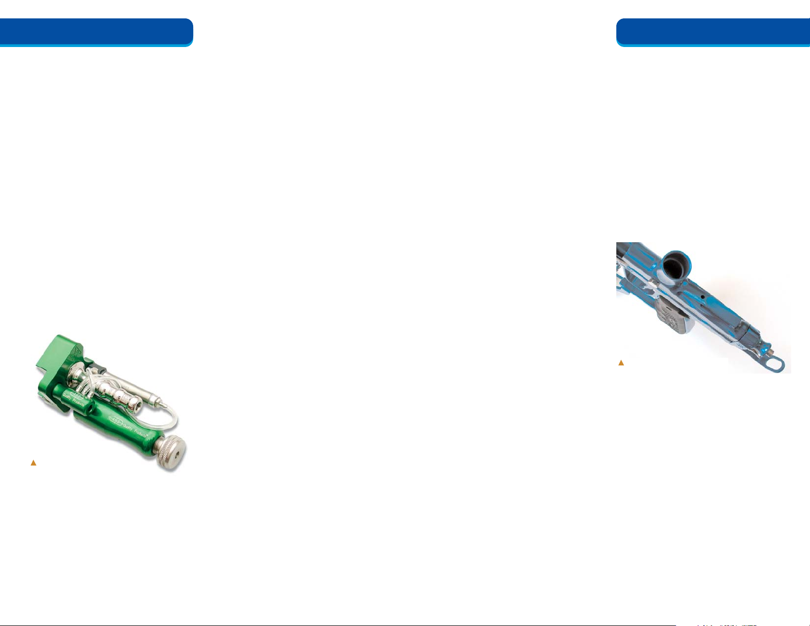
Complete Pneumatic Kit
Sear Lug Adjustment Hole (Timing)
Jack Hammer II Front Pneumatic
Regulator Adjustment
The Jack Hammer II regulator is located
below the barrel to the front of the marker body.
It regulates the pressure needed to operate the
front pneumatics. NOTE: This part is preset
from the factory and should not be adjusted on a
new marker. Adjustment will be necessary only
if the user has altered factory settings.
Page 4
ANS Xtreme Performance: GX-3/GX-4 User Manual
7
Marker timing is ADVANCED if when the
trigger is pulled slowly, the marker fires way
before the back block starts to moves back. This
indicates that there is too little contact between
the lug and the sear creating a large gap in the
firing sequence.
Marker timing is DELAYED if when the
trigger is pulled slowly, the back block moves
back before the marker fires. This indicates that
there is too much contact between the lug and
the sear.
Sear Lug timing check is now complete.
Sear Lug Adjustment
Before any adjustments are made to the
sear lug, you will first need to perform the
3-Way Shaft Adjustment and the Sear Lug
Timing Check (see instructions above). If the
timing check reveals that the marker is delayed
or advanced, an adjustment will be necessary. If
the firing sequence is at optimum performance,
no adjustment is necessary.
YOU’LL NEED:
1/8" Allen wrench (long)
ADJUSTMENT STEPS FOR ADVANCING
THE TIMING (MARKER TIMING IS
DELAYED)
1. Ensure that the marker is de-cocked.
2. Pull the Quick Pull bolt out of the back block.
3. Locate the timing hole. The timing hole is
located on top of the marker body right
behind the feed neck.
4. Locate the sear lug Allen screw. Insert the
Allen wrench into the timing hole to lock into
the sear lug. Due to variations in spring ten-
sion or main spring set-ups the wrench may
not fit immediately into the lug, but moving
the cocking rod slightly back and forth will
allow the Allen wrench to drop into the screw
head. When the wrench is locked into place
you will feel a noticeable resistance due to a
nylon anti-vibration setscrew.
5. Raising the lug. Twist the Allen wrench
counterclockwise 1/8 turn. This will decrease
contact between the sear plate and the sear
lug thus allowing the lug to slip off earlier.
NOTE: Lug adjustment should be minimal
and restricted to 1/8-turn intervals.
6. Check the adjustment. After each adjustment
(turn on the Allen wrench), replace the bolt
and fire the marker to check the adjustment
made to the firing sequence. Remember to
pull the trigger slowly when checking the
timing on the marker.
7. Repeat the adjustment until timing is correct
and the hammer releases at the right time.
ADJUSTMENT STEPS FOR DELAYING
THE TIMING (MARKER TIMING IS
ADVANCED)
1. Ensure that the marker is de-cocked.
2. Pull the Quick Pull bolt out of the back block.
3. Locate the timing hole. The timing hole is
located on top of the marker body right
behind the feed neck.
4. Locate the sear lug Allen screw. Insert the
Allen wrench into the timing hole to lock
into the sear lug. Due to variations in spring
tension or main spring set-ups the wrench
may not fit immediately into the lug, but
moving the cocking rod slightly back and
forth will allow the Allen wrench to drop
into the screw head. When the wrench is
locked into place you will feel a noticeable
resistance due to a nylon anti-vibration
setscrew.
5. Lower the lug. Twist the Allen wrench
clockwise 1/8 turn. Doing this will increase
contact between the sear plate and the sear
lug thus allowing the lug to be held a little
longer. NOTE: Lug adjustment should be
minimal and restricted to 1/8-turn intervals.
6. Check the adjustment. After each adjustment
(turn on the Allen wrench), replace the bolt
and fire the marker to check the adjustment
made to the firing sequence. Remember to
pull the trigger slowly when checking the
timing on the marker.
7. Repeat as necessary. Repeat the adjustment
until timing is correct and the hammer
releases at the right time.
Sear Lug adjustment is now complete.
6
ANS Xtreme Performance: GX-3/GX-4 User Manual
ANS
GX-3/GX-4 USER MANUAL
ANS
GX-3/GX-4 USER MANUAL
Page 5
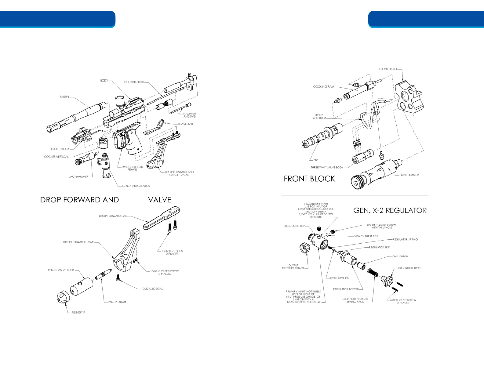
ANS Xtreme Performance: GX-3/GX-4 User Manual
9
ANS
GX-3/GX-4 USER MANUAL
8
ANS Xtreme Performance: GX-3/GX-4 User Manual
ANS
GX-3/GX-4 USER MANUAL
BLOCK PLUG
ON/OFF
Page 6
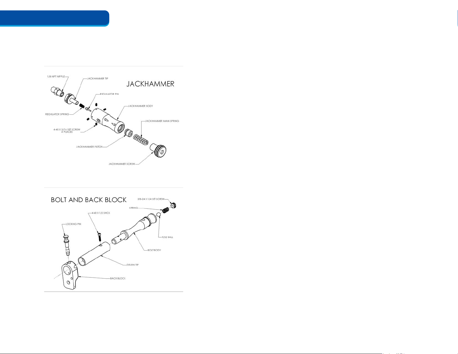
10
ANS Xtreme Performance: GX-3/GX-4 User Manual
ANS
GX-3/GX-4 USER MANUAL
 Loading...