

Page 1
anovafurnishings.com
Right Leg
Left Leg
888.535.5005 tel
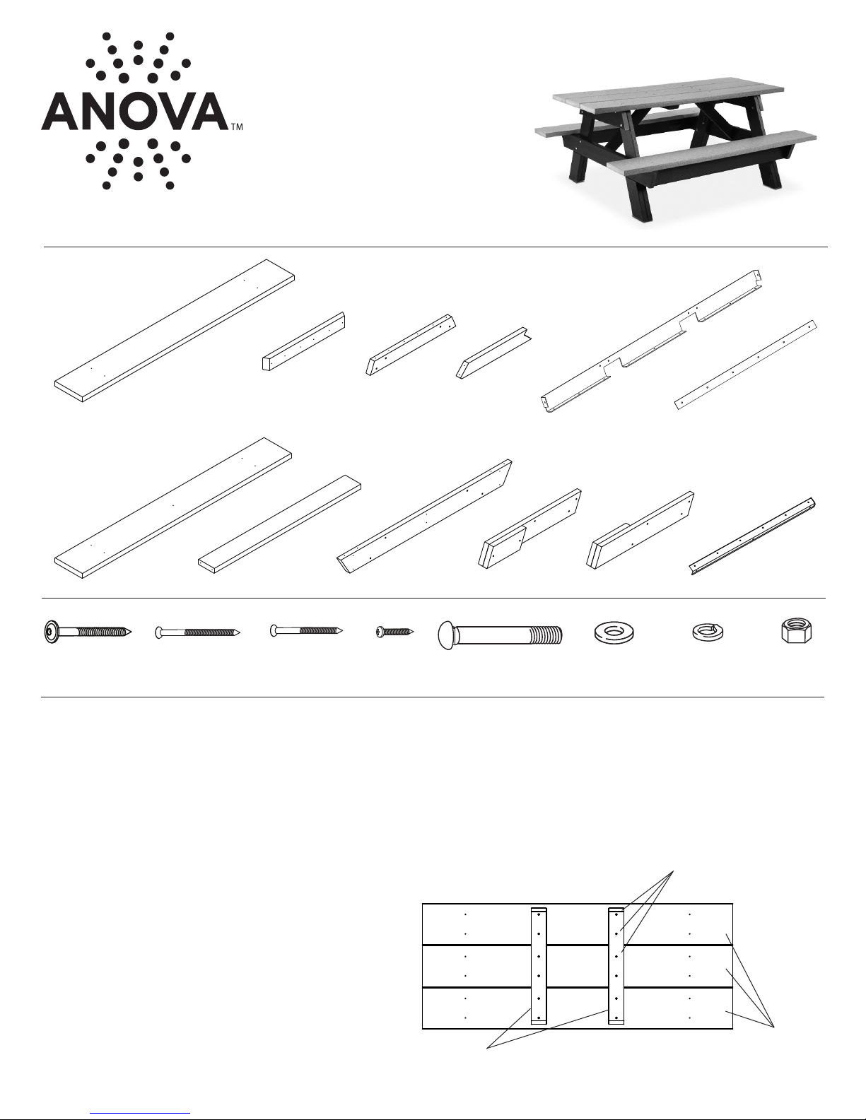
TABLE COMPONENTS:
ASSEMBLY INSTRUCTIONS
RCP6 Recycled Plastic Picnic Table
TOOLS NEEDED:
Ratchet with 9/16” Socket•
T25 Torx Driver•
T30 Torx Driver•
Phillips Head Driver•
Hammer•
3 x Table Top Plank
2 x Seat Plank
ASSEMBLY HARDWARE:
22 x
Torx T30 X 3.0”
Washer Head Screw
ASSEMBLY:
The assembly is a two-person operation.
1. Inspect the shipping container contents for damage and to determine that all components and hardware are present.
2. Assemble the Table over the shipping packaging or padded work area to avoid scratching the product.
Note: Before assembling the Nuts to the Bolts, it is recommended that a light oil or petroleum jelly be applied to the screw threads
T25 X 3.0”
Torx Head Screw
2 x Seat Stiener
8 x
2 x Angle
Brace Mount
20 x
T25 X 2.5”
Torx Head Screw
2 x Leg Mount
2 x Seat Support 2 x Right Leg
60 x
#10 X 3/4”
Phillips Screw
2 x Angle
Brace
2 x Le Leg
16 x
3/8-16 X 3.5”
Carriage Bolt
2 x Angle
Support
16 x
3/8” Flat
Washer
2 x Leg Mount Brace
16 x
3/8” Split
Washer
2 x Support Bar
16 x
3/8-16
Hex Nut
3. Lay the three Table Top Planks out on the padded work area. The Table Top Planks can be distinguished from the Seat Planks
because the Table Top Planks have four predrilled through holes and four inner pilot holes while the Seat Planks have ve
predrilled through holes. Arrange the Table Top planks with the four inner pilot holes facing up.
4. Locate the two Angle Brace Mounts. Use the T25
Torx Driver to start six T25 x 2.5” Torx Screws
into the predrilled holes in one of the Angle Brace
Mounts. Drive the Screws into the Brace Mount
until the points emerge on the other side. Place
the Angle Brace Mount over one of the inner rows
of predrilled pilot holes in the Table Top Planks,
aligning the points of the Torx Screws with the
pilot holes.
Use the T25 Torx Driver to drive the Screws into
the Table Top Planks until tight.
Repeat this step for the other Angle Brace Mount.
Angle Brace
Mounts
T25 x 2.5” Torx Screws
Table Top
Planks
Page 2
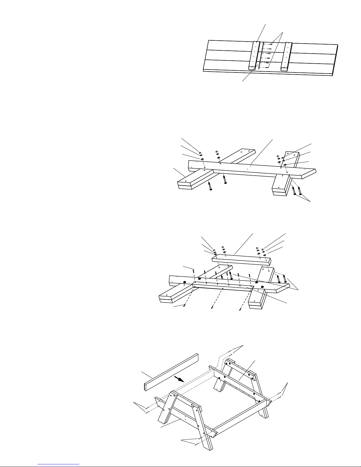
5. Install a Support Bar along the inside edge of one of the Angle Brace Mounts.
Note:
The Support Bar has small chamfers on the upper corners. Install
the Support Bar so the chamfers are away from the Table Top
Surface.
Place the Support Bar on the Table Top rst, then slide it against the
Angle Brace Mount. Make sure the Support Bar maintains contact
with the Table Top. Drive the Phillips Screws through the holes in
the Support Bar, into the Angle Brace Mount.
Install the remaining Support Bar against the other Angle Brace
Mount in the same manner.
6. Set the Table Top aside on a padded surface.
7. Locate a Le Leg and a Right Leg and insert Carriage Bolts through the two holes closest to the thick ends. Insert the Bolts from
the single-layer side toward the double-layer side. Use the Hammer to seat the Bolts. Lay the Legs out in an “A” shape with the
Thick Leg Ends facing up.
Position a Seat Support over the Legs and Bolts with the bottom of the Support contacting the thicker portion of the Leg end.
Place a Flat Washer, Split Washer and
Hex Nut on the end of each Carriage Bolt.
NOTE: Installing the Carriage Bolt in this
direction reduces the risk of being
scratched by the bolt end while using or
moving the assembled Table.
Leave the hardware nger tight so
adjustments can be made while
attaching the Seat Stieners (Step 9).
Repeat this step for the other pair of
Legs and Seat Support.
8. Locate the Leg Mounts. Place one of them at the top of each set of Legs. Insert Carriage Bolts through the Mounting Holes near
the top of each Leg and through the matching holes in the Leg Mounts. Use the Hammer to seat the Carriage Bolt and expose
the threads. Place a Flat Washer, Split Washer and Hex Nut on the end of each Carriage Bolt. Leave the hardware nger tight.
NOTE: Installing the Carriage Bolt in this
direction reduces the risk of being scratched
by the bolt end while using or moving the
assembled Table.
9. Install the Leg Mount Brace along the lower
edge of the Leg Mount. The face of the
Brace with 6 holes should be installed on
the wide face of the Leg Mount. Use nine
#10 x 3/4” Phillips Screws to fasten the
brace. Repeat this step for the other Leg
Mount Brace on the second Leg Mount
Assembly.
Thick Leg End
Phillips Screws
Hex Nut
Split Washer
Flat Washer
Hex Nut
Split Washer
Flat Washer
Phillips Screws
Support Bar
Angle Brace Mount
Seat Support
Leg Mount
Phillips Screws
Hex Nut
Split Washer
Flat Washer
Carriage Bolts
Hex Nut
Split Washer
Flat Washer
Carriage Bolts
Leg Mount Brace
10. Use the Torx T25 driver to start two T25 x 3.0” Torx Screws into the pilot holes at the end of one of the Seat Supports in the Leg
Assembly. Stop as the points of the Screws emerge from the other side of the Seat Support.
Hold the Leg Assembly upright and position one of the Seat Stieners so the pilot holes in the end of the Stiener line up with the
emerging Screw points of the Seat Support. Use the Torx T25 Driver to drive the T25 x 3.0” Torx Screws into the Seat Stiener.
Repeat this step to attach
the other Seat Stiener to
the other side of the Leg
Assembly.
Attach the other Leg
Assembly to the other end
of the Seat Stieners in the
same manner.
T25 x 3” Torx Screws
Seat Stiener
Seat Support
T25 x 3” Torx Screws
T25 x 3” Torx Screws
Seat Support
T25 x 3” Torx Screws
2 of 4
Page 3

11. Return to the Table Top Assembly. Orient the Table Top so that the top surface is facing upward. Start one T30 x 3” Washer Head
Screw into each of the corner pilot holes. Stop when the point of the screw emerges from the bottom side of the Table Top.
Carefully li the Table Top Assembly and position it over the assembled Leg Structure and line up the emerging points of the
Washer Head Screws with the appropriate pilot holes in the Leg Mount component of the assembled Leg Structure.
Use the Torx T30 Driver
to drive the Washer Head
Screws into the Leg Mount
until tight. Once these four
Screws are secured, the
remaining Washer Head
Screws can be inserted and
driven into the rest of the
Table Top pilot holes.
Aer the Table Top is
secured, tighten all of the
Carriage Bolts and Hex
Nuts in the Leg Structure.
12. Carefully turn the Table upside down onto a padded work surface.
Start two T25 x 2.5” Torx Screws into the pilot holes in the center of the both Seat Supports. Locate the two Angle Braces. Start
two T25 x 2.5” Torx Screws into the pilot holes on the notched end, just enough to hold them in place.
Position one of the Angle Braces so the
notched end ts over the edge of the Angle
Brace Mount near the center Table Top and
the other end of the Angle Brace contacts
the center of the Seat Support where the
two Torx screws are started.
While one person holds the Brace in place,
another person should drive the Torx Screws
through the Seat Support, into the end
of the Angle Brace. When those outside
Screws are secure, drive the two started
Screws through the Brace and into the
Angle Brace Mount.
Install the remaining Angle Brace in the
same manner.
13. Position one of the Angle Supports on the Table Top with the cutouts positioned over the Angle Brace Mounts. Make sure the
mounting ange is facing out toward the edge of the table. Install the nine Phillips Head Screws through the Angle Support and
into the Table Top rst.
Note: Install the Screws from the
center of the Table, alternating
outward towards the ends of the
Table.
Keep the Angle Support pressed
against the Angle Brace when
installing the screws.
Start the four corner T30
Washer Head Screws rst
T30 Washer
Head Screws
Tighten hardware
aer the Table
Top is secure
T25 x 2.5”
Torx Screws
Angle Brace Mounts
Seat Stiener removed
from illustration for clarity
T25 x 2.5”
Torx Screws
Angle Brace
Angle Brace
Leg Mount
Tighten hardware
aer the Table
Top is secure
Leg Mount
Seat Support
T25 x 2.5”
Torx Screws
Phillips Screws
Angle Brace Mounts
Angle Support with
mounting ange
outward
3 of 4
Page 4

14. Install four Phillips Head Screws through the Angle Support and into the Angle Braces, then install a Phillips Head Screw
through the ends of the Angle Support and into the Leg Mounts.
15. Install the remaining Angle Support on the other side of the Angle Braces in the same manner.
Angle Brace
Leg Mount
Phillips Head Screws
16. Carefully turn the Table right side up. Start four T30 x 3.0” Washer Head Screws into the predrilled holes near the ends of each of
the Seat Planks until the points of the screws start to emerge from the other side of the planks. Line up the points of the screws
with the predrilled holes in the Seat Supports and use the Torx T25 Driver to tighten the screws.
Place a T30 x 3.0” Washer Head Screw into the predrilled hole in the center of each Seat Plank and use the Torx T30 Driver to
tighten the screws, making sure the screws are driven into the Seat Stiener.
Install the remaining Seat
Plank in the same manner.
Move the Table to the
location where it will be
used.
Phillips Head Screws
T30 Washer
Head Screws
T30 Washer Head Screws
T30 Washer Head Screws
Furniture must not be used other than for its intended purpose and should be inspected regularly for loose, •
missing, or broken hardware, and general instability.
WARNING
CARE AND
MAINTENANCE
Furniture that is damaged or appears to be unstable must be removed from service and be repaired or replaced. •
Repairs must be made using only factory authorized parts and methods.•
Do not drag the assembled unit across any surface.•
This product requires only periodic cleaning with a sponge and a solution of mild detergent and water to •
remove surface dirt. Do not clean with a solvent or petroleum based products.
211 North Lindbergh Blvd.
St. Louis, MO 63141
tel: 888.535.5005
web: anovafurnishings.com
09/2013
 Loading...