

Page 1
Rev 9/20/18
Operator’s Manual
2052 O’Neil Rd, Macedon NY 14502
Telephone: (315) 986-8090
Fax: (315) 986-8091
www.ankom.com
Page 2

This page intentionally left blank
Page 3

Table of Contents
Introduction .................................................................................................................................................................. 5
Warranty ....................................................................................................................................................................... 5
Filter Bags ..................................................................................................................................................................... 5
Contact Information ..................................................................................................................................................... 5
Method Comparison (Manual vs. Automated) ............................................................................................................. 6
Instrument Description ................................................................................................................................................. 7
Service Access Position ............................................................................................................................................... 10
Operating Environment .............................................................................................................................................. 10
Safety Precautions ...................................................................................................................................................... 10
Instrument Installation ............................................................................................................................................... 11
Dietary Fiber Analysis Support Items .......................................................................................................................... 16
Analysis Options using the ANKOM
TDF
Dietary Fiber Analyzer ................................................................................... 16
Blanks .......................................................................................................................................................................... 16
IDF/SDF Analysis ......................................................................................................................................................... 17
TDF Analysis (AOAC 991.43) ....................................................................................................................................... 31
TDF Analysis (AOAC 985.29 / 2001.03) ....................................................................................................................... 44
Protein Determination ................................................................................................................................................ 59
Ash Determination ...................................................................................................................................................... 61
Productivity Enhancement ......................................................................................................................................... 63
Status Screen .............................................................................................................................................................. 67
Fault Handling ............................................................................................................................................................. 71
Diagnostics Mode ....................................................................................................................................................... 73
Periodic Maintenance ................................................................................................................................................. 81
Troubleshooting & Replacement Parts ....................................................................................................................... 82
QC / Calibration Checks .............................................................................................................................................. 83
Appendix A – Reagents (AOAC 991.43, 985.29, 2001.03) .......................................................................................... 89
Appendix B – Instrument Out-of-use Procedure ........................................................................................................ 91
Appendix C – De-fatting Procedure ............................................................................................................................ 93
Appendix D – Accessories (sold separately) ............................................................................................................... 95
Page 4

This page intentionally left blank
Page 5
Operator’s Manual
Rev 9/20/18 pg. 5
Introduction
ANKOM Technology designs, manufactures, and markets instruments and support products used by analytical laboratories
around the world in the food, feed, bio-energy, agricultural, and environmental industries. ANKOM Technology can provide
you with products for determining or monitoring dietary fiber, detergent fiber, crude fiber, fat, digestibility, microbial
fermentation (anaerobic or aerobic) and more.
Committed to Total Customer Satisfaction, ANKOM designs every product based on a thorough assessment of customer needs.
Congratulations on your purchase of the ANKOM
TDF
Dietary Fiber Analyzer. We are confident that this product will
effectively serve your needs.
The ANKOM
TDF
Dietary Fiber Analyzer was designed to eliminate most of the manual steps required by the method. This
reduces technician variation, increasing precision. By carefully following the operating instructions in this manual you will
understand the details of sample and filter bag handling as well as instrument control, helping you to achieve the best possible
results.
Please review the entire manual before you begin operating this product.
Warranty
ANKOM Technology warrants the ANKOM
TDF
Dietary Fiber Analyzer against any defects in workmanship or material for one
year after the original date of purchase. This warranty does not include damage to the instrument resulting from neglect or
misuse. During the warranty period, should any failure result from defects in workmanship or materials, ANKOM Technology
will, at its discretion, repair or replace the instrument free of charge.
Extended warranties are available upon request.
Filter Bags
Use ANKOM Technology filter bags (part #’s DF-I, DF-S, DF-FT) in your ANKOM
TDF
Dietary Fiber Analyzer. Filter bags can
be purchased from ANKOM Technology or from your local authorized ANKOM distributor.
Contact Information
Committed to your total satisfaction, we are always available to help you get the most from your ANKOM products and to
receive any comments or suggestions you might have to help us improve.
For any questions or suggestions regarding your instrument, please contact us at:
• Telephone: (315) 986-8090
• Fax: (315) 986-8091
• Email: service@ankom.com
• www.ankom.com
Page 6
Operator’s Manual
pg. 6 Rev 9/20/18
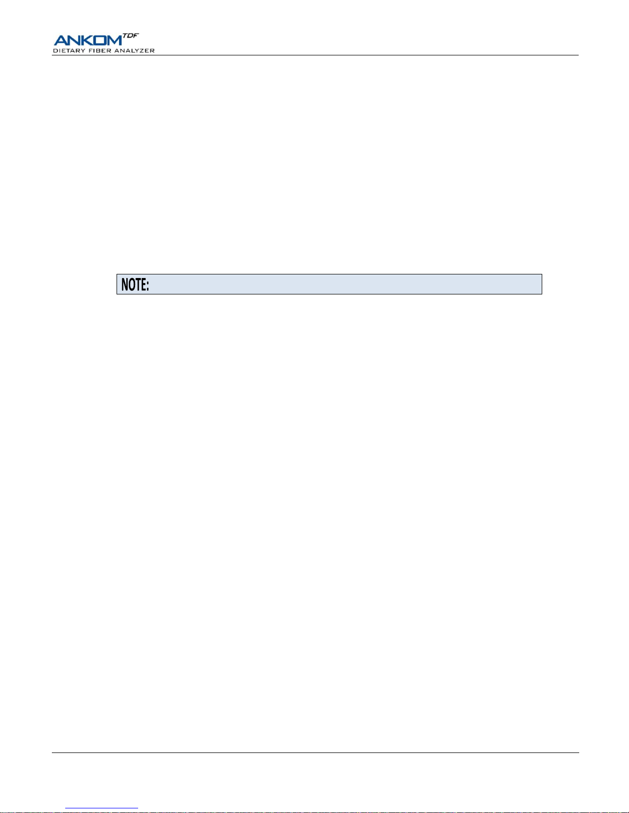
Method Comparison (Manual vs. Automated)
AOAC 991.43 Method – IDF/SDF assay without automation
Below is the AOAC 991.43 method flow done manually by a technician using glass crucibles and beakers, vacuum to assist
with filtering, and water baths to control temperature and mixing. DE refers to Diatomaceous Earth.
Prepare for Test
Digest Sample
Isolate IDF Residue
Isolate SDF Residue
1
Prepare crucibles
5 Heat to 95°C
17
Transfer to filter
26
Add 95% EtOH to fitrate
1a
Ash crucibles overnight
6 Add buffer
18
Filter with vacuum assist
27
Precipitate for 60 min
1b
Clean with vacuum
7 Add Amylase
19
Scratch filter bed as
needed
28
Transfer to filter
1c
Soak 1 hr @ room temp
8 Digest at 95°C for 35 min
29
Filter with vacuum assist
1d
Rinse with 3 solutions
9
Scrape beaker walls and
rinse with H2O to move
all residue to bottom
20
Rinse with 70°C H2O
30
Scratch filter bed as
needed
1e
Prepare DE filter bed
21
Rinse with 78% EtOH
1f
Dry @ 130°C
22
Rinse with 95% EtOH
31
Rinse with 78% EtOH
1g
Cool 1 hr and weigh
10
Cool to 60°C
23
Rinse with Acetone
32
Rinse with 95% EtOH
2
Weigh samples
11
Add Protease
24
Dry IDF residue
33
Rinse with Acetone
3
Prepare H2O bath(s)
12
Digest at 60°C for 30 min
25
Weigh IDF residue
34
Dry SDF residue
4
Place samples in beakers
13
Add HCl
35
Weigh SDF residue
14
Add AMG
15
Check/adjust pH
Calculate Results
16
Digest at 60°C for 30 min
36
Correct for Protein
37
Correct for Ash
38
Calculate results using
weights and corrections
AOAC 991.43 Method – IDF/SDF assay with ANKOM
TDF
Dietary Fiber Analyzer automation
Below is the AOAC 991.43 method flow when using the ANKOM
TDF
Dietary Fiber Analyzer. Steps highlighted in YELLOW
represent tasks done by a technician. Steps highlighted in GREEN (1a-1g, 9, 19, and 30) are no longer needed because of Filter
Bag Technology. All other steps (including mixing) are done automatically by the ANKOM
TDF
Dietary Fiber Analyzer under
computer control. DE refers to Diatomaceous Earth.
Prepare for Test
Digest Sample
Isolate IDF Residue
Isolate SDF Residue
5 Heat to 95°C
17
Transfer to filter
26
Add 95% EtOH to fitrate
6 Add buffer
18
Filter with pressure assist
27
Precipitate for 60 min
7 Add Amylase
28
Transfer to filter
8 Digest at 95°C for 35 min
29
Filter with pressure assist
20
Rinse with 70°C H2O
21
Rinse with 78% EtOH
22
Rinse with 95% EtOH
31
Rinse with 78% EtOH
1
Weigh filter bags
10
Cool to 60°C
23
Rinse with Acetone
32
Rinse with 95% EtOH
2
Weigh DE and samples
11
Add Protease
24
Dry IDF residue
33
Rinse with Acetone
3
Install filter bags
12
Digest at 60°C for 30 min
25
Weigh IDF residue
34
Dry SDF residue
4
Add DE & Sample to bags
13
Add HCl
35
Weigh SDF residue
14
Add AMG
15
Check/adjust pH
Calculate Results
16
Digest at 60°C for 30 min
36
Correct for Protein
37
Correct for Ash
38
Calculate results using
weights and corrections
This section is just an overview of how the ANKOM
TDF
Dietary Fiber Analyzer
executes the AOAC 991.43 method. Please see the “IDF/SDF Analysis” and “TDF
Analysis” sections of this manual for detailed instructions on how to perform
IDF/SDF and TDF assays with the analyzer.
Page 7
Operator’s Manual
Rev 9/20/18 pg. 7
Instrument Description
The ANKOM
TDF
Dietary Fiber Analyzer is designed to efficiently, accurately, and precisely recover Insoluble Dietary Fiber
(IDF), Soluble Dietary Fiber (SDF), and Total Dietary Fiber (TDF) residue from food and/or feed samples in accordance with
the AOAC 991.43, AOAC 985.29, AOAC 2001.03, AACC 32-07.01, and NMKL 129, 2003 methods.
Contact ANKOM Technology about an upgrade to Total Integrated Dietary Fiber
(AOAC 2009.01 and 2011.25 methods). See the Diagnostics section of this
document for instructions on how to enable these methods.
Enabled by Filter Bag Technology, the instrument can run six digestion and six precipitation processes at the same time. The
filter bags are designed to capture the appropriate fiber particles while allowing all non-fiber components to pass through. The
instrument will use IDF bags and SDF bags when configured to recover IDF and SDF residue. The instrument will use IDF
Flow-Thru bags and SDF bags when configured to recover TDF residue.
The automated fiber recovery is achieved by first digesting samples within bags using enzyme treatments. Depending on the
filter bag configuration, the instrument then collects the IDF and SDF residue using two separate filters, or collects the TDF
residue using one filter. Once captured in the filters the residue is dried, weighed, and corrected for protein and ash content to
determine the IDF, SDF, and/or TDF values.
Digestion, precipitation, rinse (H2O and EtOH), and filter operations are performed by the instrument, eliminating manual
transfer and filtration steps. An on-board computer precisely controls process temperatures, agitation, and fluid delivery along
with digestion, precipitation, and filtration times.
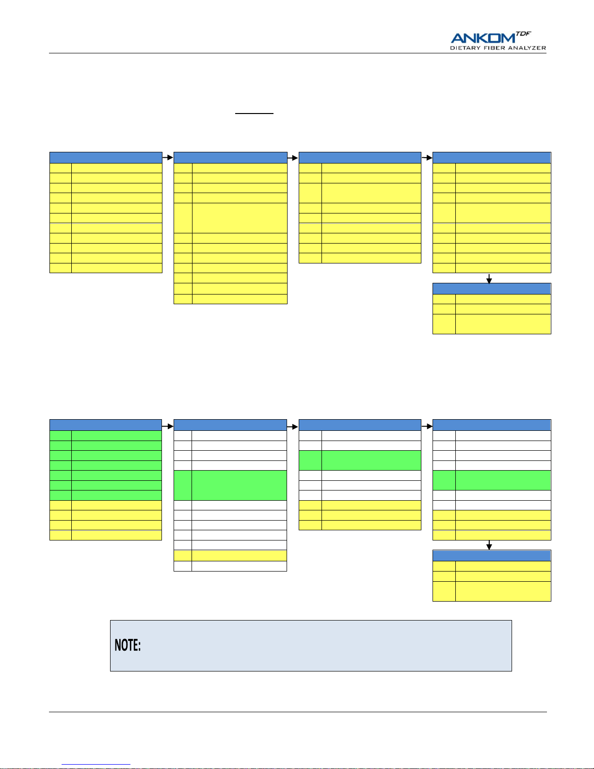
External Components – Front View
Touch
Screen
Display
Filtrate Cup
(TDF53 - #1 of 6)
Waste Tray
IDF Station (#4 of 6)
SDF Delivery
Nozzle
(#1 of 6)
Clamp Bar A
Clamp Bar B
Control
Buttons
Hook for SDF Bag
(#3 of 6)
IDF Delivery
Nozzle
(#1 of 6)
Control Panel (TDF17)
Clamp Bar D
Clamp Bar C
SDF Station (#6 of 6)
Heating Paddle (#1 of 6)
Mixing Pad
(#2 of 6)
Service Access
Screw #1
Service Access Screw #2
Front Cover
(In UP position)
Pressure Gauge
Page 8
Operator’s Manual
pg. 8 Rev 9/20/18
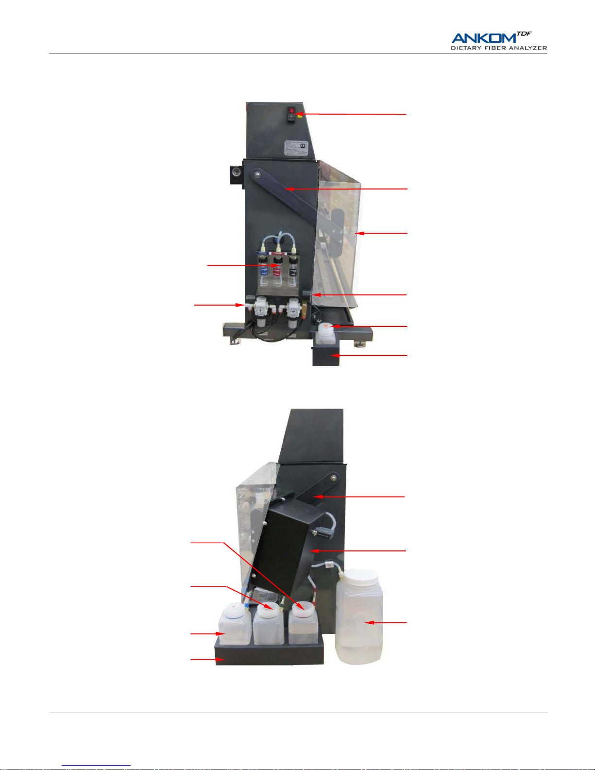
External Components – Left Side View
External Components – Right Side View
Control Panel (TDF17)
95% EtOH Container (TDF42)
HCl Container (TDF38)
Enzyme Containers
(TDF35, TDF36, TDF37)
Nitrogen Supply Port
80-100 psi
(5.5-6.9 bar)
Front Cover Arm
Power Switch
Front Cover (TDF56)
78% EtOH Container (TDF41)
Buffer Container (TDF39)
Distilled Water Container (TDF40)
Front Cover Arm
Three Container Holder
Single Container Holder
Pressure Gauge
Page 9
Operator’s Manual
Rev 9/20/18 pg. 9
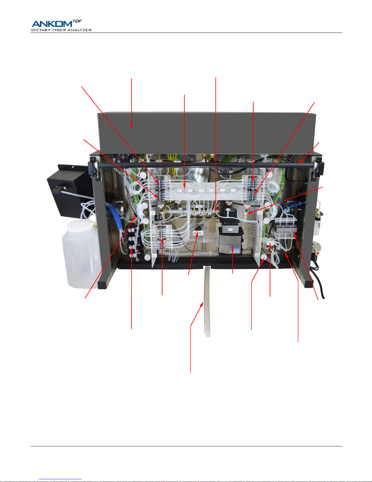
Internal Components – Rear View
N2
Check Valve
(1 of 12)
Main Electrical Cabinet
IDF Inlet Valve
Stations 4, 5 & 6
SDF Inlet Valve
Stations 4, 5 & 6
In-Line Heater
Tubing Support Panel
IDF Inlet Valve
Stations 1, 2 & 3
SDF Inlet Valve
Stations 1, 2 & 3
Waste Valves
(1 – 6)
Supply Valves
− Water
− Buffer
− 78% EtOH
− 95% EtOH
Vacuum Sensor
Supply
Manifold
Clamp Bar Cylinder
(1 of 8)
HCl
Supply Valve
Peristaltic
Pump
Pressure
Sensors
Drain Tube
Supply Valves
− Amylase
− Protease
− AMG
Torsion Bar (for
Front Cover)
Page 10
Operator’s Manual
pg. 10 Rev 9/20/18
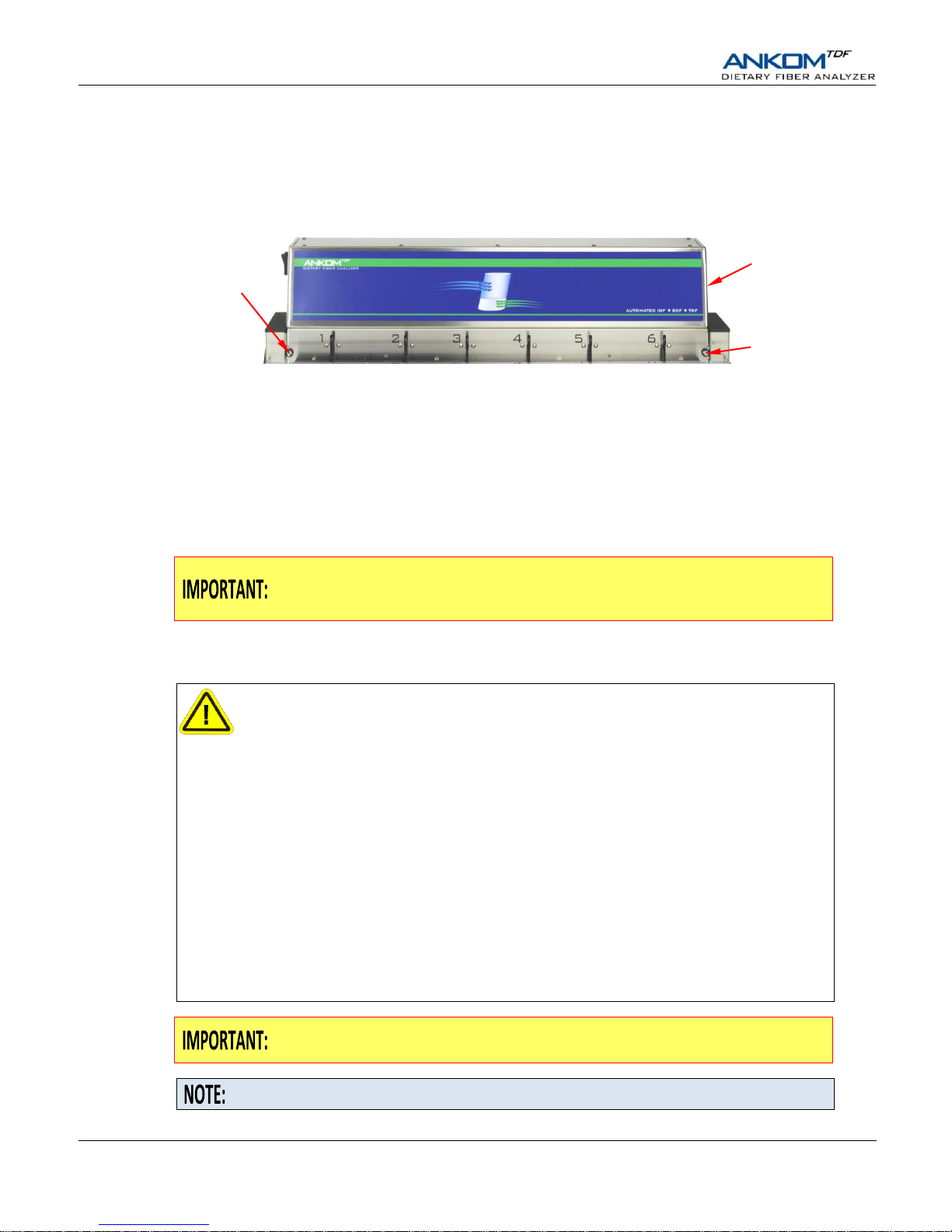
Service Access Position
If your instrument must be located in such a way as to restrict access to the back, you can tilt it forward to access the rear of the
instrument by removing the two Service Access Screws on the front of the instrument and gently pulling the top of the Main
Electrical Cabinet forward and down. The instrument will pivot at its center.
Operating Environment
Your ANKOM
TDF
Dietary Fiber Analyzer is designed to operate within the following environments:
• Ambient Temperature Range: 19°−30°C
• Humidity: 20–60% RH
• Power: 100V−120V ~ 50/60Hz 15A
220V−240V ~ 50/60Hz 8A
If after running this instrument you plan to leave it unused for 1 week or longer, you
must clear out the fluid lines to ensure proper operation. See “Appendix B –
Instrument Out-of-use Procedure” for more information.
Safety Precautions
Hot Surfaces – Do NOT touch the Heating Paddle surfaces during operation. The
surface can exceed 100°C (212°F). Failure to observe this caution may result in
burns.
Hazardous Voltages – Do NOT operate the instrument with the back of the Main
Electrical Cabinet removed. Hazardous voltages are present during operation. Failure
to observe this caution may result in electrical shock or electrocution.
Hazardous Materials – Ethanol is used within this instrument. Follow both local
and federal regulations for vent hood requirements when operating this instrument.
Do NOT heat seal or place filter bags in an oven until all acetone has evaporated.
Failure to observe this caution may be hazardous to your health.
WARNING: Attempts to override safety features or to use this instrument in a
manner not specified by ANKOM Technology voids the warranty and may result in
serious injury or even death.
This system is designed to meet and/or exceed the applicable standards of CE and
CSA.
The Power Switch must be in the OFF position before plugging the instrument Power
Cord into the power source.
Please review the entire manual before you begin operating this instrument.
Service Access
Screw #1
Service Access
Screw #2
Main Electrical
Cabinet
Page 11
Operator’s Manual
Rev 9/20/18 pg. 11
Instrument Installation
Site Requirements
To install and operate the ANKOM
TDF
Dietary Fiber Analyzer you will need the following:
• Adequate power (see “Operating Environment” section of this manual)
• Drain or waste container to capture waste fluids
• Bench space that can accommodate the instrument dimensions of 132 cm (52”) L x 92 cm (35”) H x 77 cm (30”) D
• 80-100 psi (5.5-6.9 bar) Nitrogen Supply and connection tubing
Because the instrument is powered by pneumatics, do NOT run it without an
adequate Nitrogen Supply. You can run approximately 5 to 10 full assays
(IDF/SDF or TDF) with a 304 cu ft tank of nitrogen.
Instrument Installation Procedure
To install the ANKOM
TDF
Dietary Fiber Analyzer, follow the steps below.
1. Unpack and place the instrument where it will be used.
The instrument shipping container consists of three separate cardboard pieces: a top, a bottom, and a sleeve that forms the
body of the container. Remove the top and the sleeve of the instrument shipping container. Lift the instrument off of the
shipping container bottom and place it on a surface that is firm and level in an area near a Nitrogen Supply and a drain or
chemical waste container.
Waste fluids are drained from the instrument using gravity. Therefore, position the
instrument so that the drain tube can run down from the Waste Tray.
The instrument must not be subjected to excessive shock, vibration, dirt, moisture, oil, or other fluids.
Ethanol is used within this instrument. Follow both local and federal regulations for
vent hood requirements when installing this instrument.
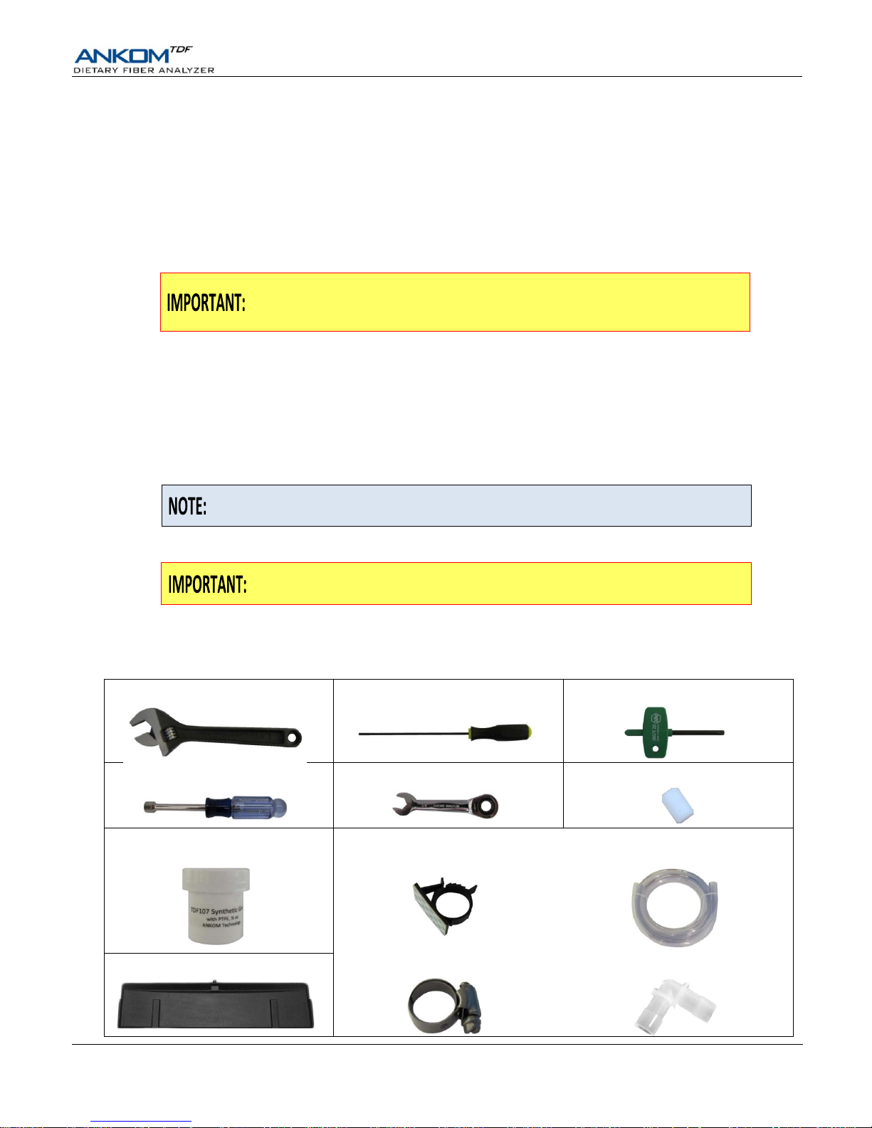
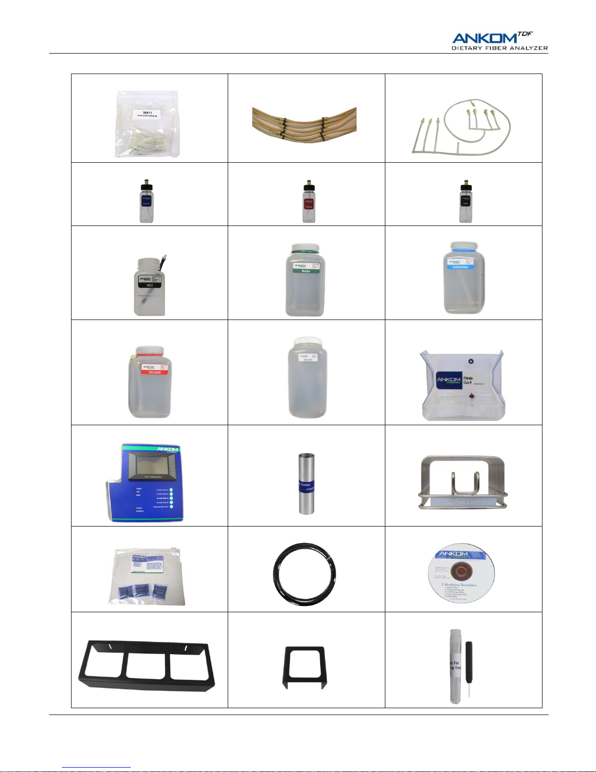
2. Unpack the attachments and accessories.
Within the shipping container is a cardboard box containing attachments and accessories. Open the box and verify that all
of the following items are there.
1 – Crescent Wrench (204.9)
1 – 1/8” Allen Wrench (Z303)
1 – T-Handle Torx T20 Driver (Z276)
1 – 3/8” Nut Driver (8416)
1 – 3/8” wrench (8418)
2 – Spray Tips (TDF44)
1 - TDF Synthetic Grease (TDF107)
1 – Drain Hose Assembly (TDF96) that includes these five parts
1 - Adhesive Clamp (8133) 1 – Drain Tube (8132)
1 – Drain Tray (8002)
1 – Drain Tube Clamp (6138)
2 – Drain Tube Elbow Connectors (8288)
Page 12
Operator’s Manual
pg. 12 Rev 9/20/18
1 – Pinch Valve Tubing Set (TDF71)
1 – Long Life Pump Tube Set (TDF99)
1 - Line Flush Tubing assy (TDF70)
1 – Amylase Container assy (TDF35)
1 – Protease Container assy (TDF36)
1 – AMG Container assy (TDF37)
1 – HCl Container assy (TDF38)
1 – Mes-Tris Buffer Container assy (TDF39)
1 – Distilled Water Container assy (TDF40)
1 – 78% EtOH Container assy (TDF41)
1 – 95% EtOH Container assy (TDF42)
6 – Filtrate Cups (TDF53)
1 – Control Panel assy (TDF17)
1 – Bag Weigh Holder assy (TDF52)
1 – Drying Rack assy (TDF50)
2 – Desiccant Pouches (X45)
1 – 3 meter Air Tube (8216)
1 – CD with Calculation Templates
1 – three container holder (8191)
1 – single container holder (8192)
1 – Spray Tip Cleaning Tool Kit (TDF94)
Page 13
Operator’s Manual
Rev 9/20/18 pg. 13
2 – Container Filters (8202)
1 – Buffer Filter (8203)
4 – Bolts (5626)
4 – Nuts with star washers (167)
4 – Acorn Nuts (8409)
1 – Lighted Magnifier (TDF45)
2 – Fuses (8305-15A or 8306-8A)
Accessories specific to the 2009.11 & 2011.25 method upgrades can be found in
the "Automated AOAC 2009.01/2011.25 and AACC 32-45.01 method" addendum.
3. Place the Waste Tray under the front of the instrument.
With the Drain Tube connector pointing away from you, slide the tray under the front of the instrument until it cannot go
back any farther. (When the tray is in place, the side ridges will contact the front face of the steel frame.)
4. Place the six Filtrate Cups on the Waste Tray.
If filtrate collection is required for further analysis, leave the red plug in the lower port near the bottom of each of the
filtrate cups. If filtrate collection is not needed, keep the filtrate cups in place on the drain tray. However, the red plug can
be pulled from the lower port to drain the filtrate into the drain tray. Store the plug in the upper port.
5. Connect the Drain Tube to the Waste Tray.
Connect and secure the Drain Tube to the Waste Tray using the supplied Drain Tube Clamp. Run it to either a drain or a
waste container, avoiding twists in the tube. If necessary cut the Drain Tube and use the Elbow Connectors to meet the
needs of your location.
As needed, place the Adhesive Clamp (8133) between the Drain Tube Clamp and the Elbow Connector to create the
appropriate tube slope for good fluid flow.
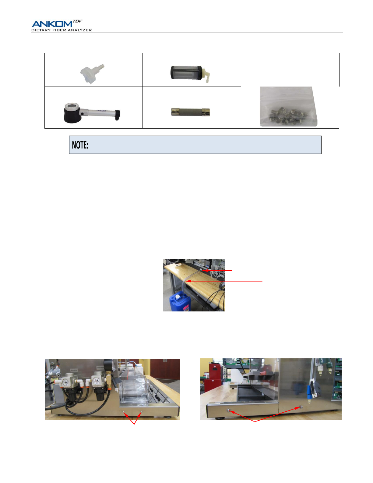
6. Connect the Chemical Container Holders to the feet of the instrument.
Remove the nuts from the outside of the left and right feet of the instrument. Slide the single container holder onto the
bolts on the left foot and the three container holder onto the bolts on the right foot. Secure the holders using the nuts.
Bolts to attach the
three container holder
Bolts to attach the
single container holder
Elbow Connector
Drain Tube Clamp
Page 14
Operator’s Manual
pg. 14 Rev 9/20/18
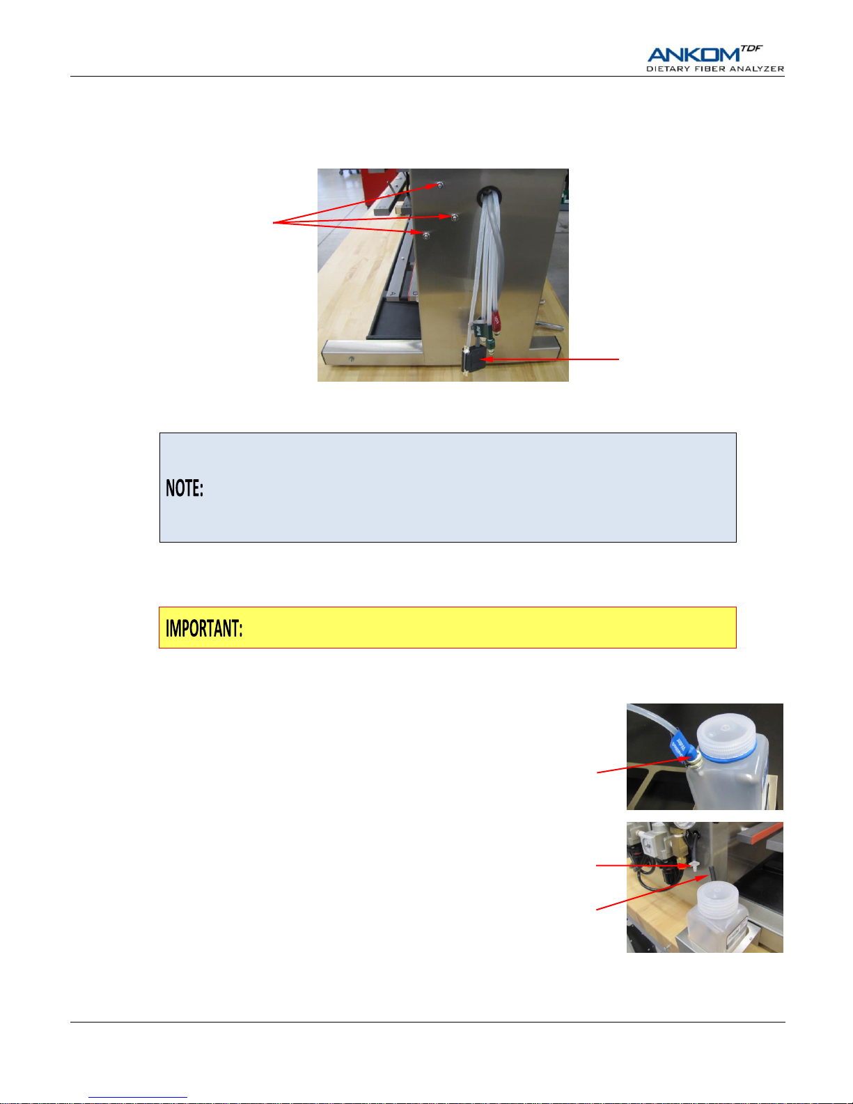
7. Connect the Control Panel to the instrument.
Remove the nuts from the right side of the instrument. Connect the 25 pin connector from the instrument to the Control
Panel. Slide the Control Panel onto the bolts and secure it in place using the nuts.
8. Place the Chemical Containers in their holders.
If you are going to run an IDF/SDF or TDF analysis immediately after installing
the instrument, fill the Chemical Containers above the Minimum Level lines and
fill the Enzyme Containers with at least 15 ml of solution before connecting the
containers to the instrument. See Appendix A for the chemical preparations.
Do NOT fill the Chemical and Enzyme Containers if the instrument is going to sit
unused after installation.
Place the HCl Container in the holder on the left side of the instrument. In the holder on the right side of the instrument,
place the Distilled Water Container in the front section, the Buffer Container in the middle section, and the 78% EtOH
Container in the back section. The 95% EtOH Container sits on the bench behind the container holder.
To ensure proper fluid delivery, you must use the Chemical Containers provided
with the instrument and place them in their specified locations.
9. Connect the Chemical Containers to the corresponding tubes.
The Chemical Containers and associated tubes are all
labeled and color-coded for easy connection. The large
containers on the right side of the instrument also have
push-on connectors. Make sure that you hear a click
sound when you connect the tubes to the containers.
On the left side of the instrument is a black tube with an
HCl label that has a white barbed fitting on its end. Push
the white barbed fitting into the black tube connected to
the HCl container.
Push-on
Connector
Bolts for
Control Panel
25 pin connector
Barbed
Fitting
Black tube connected
to HCl container
Page 15
Operator’s Manual
Rev 9/20/18 pg. 15
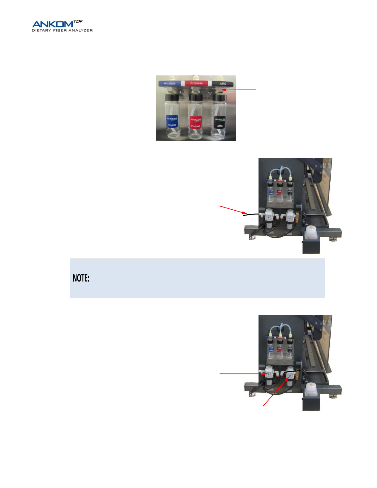
10. Connect the Enzyme Containers to the corresponding ports.
The Enzyme Containers connect into labeled, color-coded ports on the left side of the instrument using push-on
connectors. Make sure that you hear a click sound when you connect the enzyme containers to the ports.
11. Connect the Nitrogen Supply to the Nitrogen Supply Port.
Connect the 3 meter Air Tube (8216) that came with the
instrument to the Nitrogen Supply Port on the instrument
and to the Nitrogen Supply.
If you want to use a separate tube to connect your instrument to a Nitrogen Supply,
the Nitrogen Supply Port has a Push-to-Connect fitting that accepts ¼” OD tubing.
Acceptable tubing materials include Nylon, Polyurethane, Polyolefin, and
Polytetrafluoroethylene (PTFE). The tubing material must be suitable for the
specified pressure.
12. Verify that the High and Low Pressure Regulators are set properly.
Verify that the High Pressure Regulator is set to 50 psi (3.5 bar), and the
Low Pressure Regulator is set to 4-6 psi (0.3-0.4 bar).
Push-on
Connector
Nitrogen Supply Port
80-100 psi
(5.5-6.9 bar)
High Pressure Regulator
50 psi
(3.5 bar)
Low Pressure Regulator
4-6 psi
(0.3-0.4 bar)
Page 16
Operator’s Manual
pg. 16 Rev 9/20/18
Dietary Fiber Analysis Support Items
The following support items needed to perform the fiber analysis may be purchased separately:
Item
ANKOM Part #
Electronic Balance with four-place readout
TB
Electronic Balance Software
TBS
Heat Sealer for sealing the filter bags
HS (120V), HSi (220V)
IDF Filter Bags
DF-I
SDF Filter Bags (used for SDF and TDF procedures)
DF-S
IDF Flow-Thru Bags (TDF procedure only)
DF-FT
Solvent Resistant Marker
F06
Rinse Stand
TDF51
Diatomaceous Earth (DE)
DE1, DE2
Drying Oven
Ashing Oven
Protein Determination Equipment (Kjeldahl is recommended)
Analysis Options using the ANKOM
TDF
Dietary Fiber Analyzer
The ANKOM
TDF
Dietary Fiber Analyzer can be configured to recover IDF and SDF residue, or to recover TDF residue. The
following describes these analyses along with their specific filter bag configurations.
Analysis Name
Analysis Description
Upper Bag
Lower Bag
IDF/SDF
(991.43)
This analysis is used to determine IDF and SDF residue separately
using two different filter bags. TDF is calculated by adding the IDF
and SDF residue weights corrected for protein and ash content.
IDF
SDF
TDF
(991.43, 985.29 &
2001.03)
This analysis is used to determine TDF residue in one filter. In this
analysis, the TDF value consists of the weighed residue corrected
for protein and ash.
IDF Flow-Thru
(no filter)
SDF
A computer controlled Diagnostics mode is provided through the Control Panel for maintenance and troubleshooting purposes.
To maximize productivity, this instrument also allows a user to start new procedures (IDF/SDF and TDF) before the previous
ones have completed. See the “Productivity Enhancement” section of this manual for details.
Contact ANKOM about an upgrade to Total Integrated Dietary Fiber (AOAC
2009.01 and 2011.25 methods). See the Diagnostics section of this document for
instructions on how to enable these methods.
Blanks
BLANK values are used in the IDF, SDF, and TDF calculations. The following BLANK values (based on extensive research
done in the ANKOM lab) are the default values loaded in the IDF_SDF and TDF spreadsheets in the MS-Excel workbook
provided with the instrument.
IDF (AOAC 991.43 method): -0.0072 TDF (AOAC 991.43 method): -0.0047
SDF (AOAC 991.43 method): -0.0030 TDF (AOAC 985.29 method): -0.0028
You do not need to run BLANKS with every set of samples. However, if you want to determine your own BLANK values,
especially when you change chemical lots, ANKOM recommends that the BLANK value in the IDF, SDF, and TDF
calculations be the average of at least 18 BLANK values.
If you determine your own BLANK values, you can overwrite the values currently in the MS-Excel spreadsheets.
Page 17
Operator’s Manual
Rev 9/20/18 pg. 17
IDF/SDF Analysis
An IDF/SDF analysis measures the amount of IDF and SDF within a given sample. This requires the use of ANKOM DF-I and
DF-S filter bags. When starting a new run, the ANKOM
TDF
Dietary Fiber Analyzer must have bags installed at all stations (a
total of twelve bags).
To enhance the productivity of your instrument, you can begin the IDF process of a
new run while the SDF process of a previous run is finishing. See the “Productivity
Enhancement” section of this manual for more details.
To perform an IDF/SDF analysis, follow the steps below.
1. Prepare chemicals and enzymes.
When using the ANKOM
TDF
Dietary Fiber Analyzer for the AOAC 991.43, AACC 32-07.01, and NMKL 129,2003
methods use the chemicals and enzymes referred to therein. See Appendix A of this manual for the list of chemicals and
enzymes and the instructions for how to prepare them for use in this instrument.
2. De-fat your samples as needed according to the official methods. See "Appendix C – De-fatting
Procedure" in this manual for an ANKOM procedure.
3. Label the filter bags using a Solvent Resistant Marker.
4. Prepare for data collection.
You will need a place to store the data collected during this analysis. For your convenience a CD titled “Calculation
Templates” was included with the instrument. This CD has data spreadsheets that can be used for this analysis. Please
read the “Instructions” tab in the MS-Excel file for information about the spreadsheets.
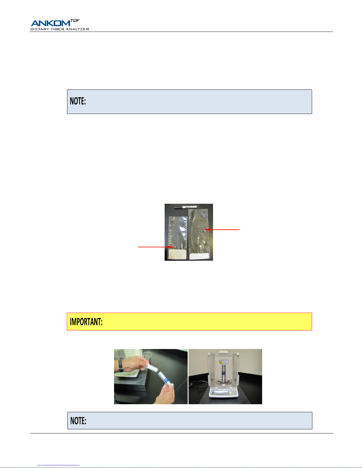
5. Weigh filter bags.
Using a Bag Weigh Holder is critical to eliminate the effects of static electricity
during the weighing process.
Roll or fold each bag and place it in a tared Bag Weigh Holder. Place the Bag Weigh Holder in the center of a balance
and record the weight.
Because different balances have different sensitivities, the Bag Weigh Holder
should be placed in the center of the balance for best results.
IDF Bag (shorter bag)
SDF Bag (longer bag)
Page 18
Operator’s Manual
pg. 18 Rev 9/20/18
6. Weigh Diatomaceous Earth (DE).
DE is used during fiber analysis to enhance the flocculation and filtration of the SDF fraction. Place ca 1 g of DE in each
of six tared and numbered tins and record the weights.
7. Weigh Samples.
Place 0.50.05 g of sample in each of six tared and numbered tins and record the weights.
A larger sample (1.0 g) can be used if a larger aliquot is needed to improve
precision.
8. Turn the instrument power on.
When you turn the power on, the instrument will run through an initialization process and the Control Panel will turn on.
9. On the Touch Screen Display, select the instrument function you would like to perform.
The Control Panel on the ANKOM
TDF
Dietary Fiber Analyzer uses Touch Screen technology. To operate the instrument
you will press identified buttons on the Touch Screen Display and buttons below the screen.
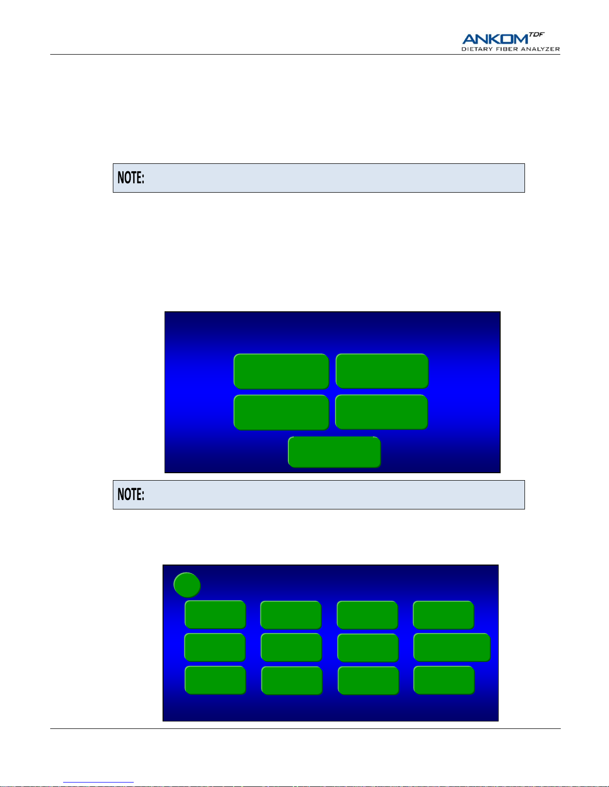
When your instrument is initialized and ready to operate, the following screen will be displayed.
Although the instrument works in accordance with AACC and NMKL methods, the
Touch Screen Display only refers to the AOAC methods.
9.1 If this is the first time the instrument is being operated after being installed, or after sitting unused for a period of
time (see Appendix B), or after tubing was replaced, the lines must be charged to avoid a Vacuum Sensor Fault.
To charge the lines follow the steps below.
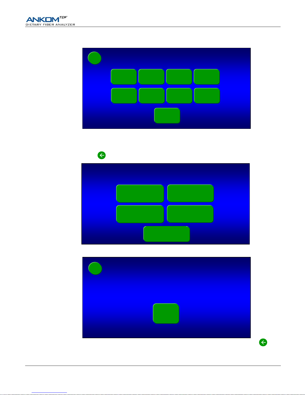
9.1.1 Press the Diagnostics button on the “Select a Function” screen. The following screen will be displayed.
Diagnostics
Touch Screen Display version: A.AA
SPLat controller software version: vX.XX dd-mm-yy
Pump Tube
Test
Expert Mode
Faults
Service
Mode
Clear IDF /
SDF lines
Digestion
Times
Heater Test
Temperatures
Pressures
Line Charge
Motor Test
Valve Test
Select a Function
AOAC 991.43
IDF/SDF
AOAC 985.29
TDF
Diagnostics
AOAC 991.43
TDF
AOAC 2001.03
TDF
←
Page 19
Operator’s Manual
Rev 9/20/18 pg. 19
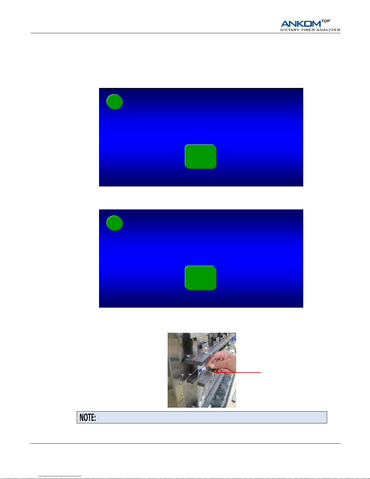
9.1.2 Press the Line Charge button. The following screen will be displayed.
9.1.3 Press the ALL button to charge all of the lines. Each button will change color as the associated line is being
charged. All lines are charged when all of the buttons return to their original green color.
9.1.4 Press the back button twice. The following “Select a Function” screen will be displayed again.
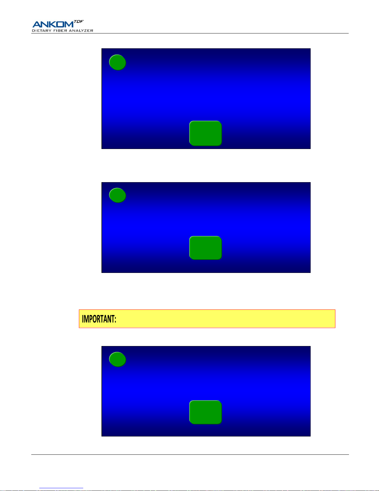
9.2 Press the AOAC 991.43 IDF/SDF button. The following screen will be displayed.
Notice that the function you selected is now displayed in the top right corner of the screen and a back button
is displayed in the top left corner of the screen.
SDF Bags (and clamp bar D) installed?
←
AOAC
991.43
IDF/SDF
Select a Function
AOAC 991.43
IDF/SDF
AOAC 985.29
TDF
Diagnostics
AOAC 991.43
TDF
AOAC 2001.03
TDF
Line Charge
Amylase
Protease
AMG
HCl
EtOH78
EtOH95
Water
Buffer
ALL
Vacuum xx.x
cur: - x.x
max: - x.x
←
Page 20
Operator’s Manual
pg. 20 Rev 9/20/18
10. Install SDF filter bags on the ANKOM
TDF
Dietary Fiber Analyzer.
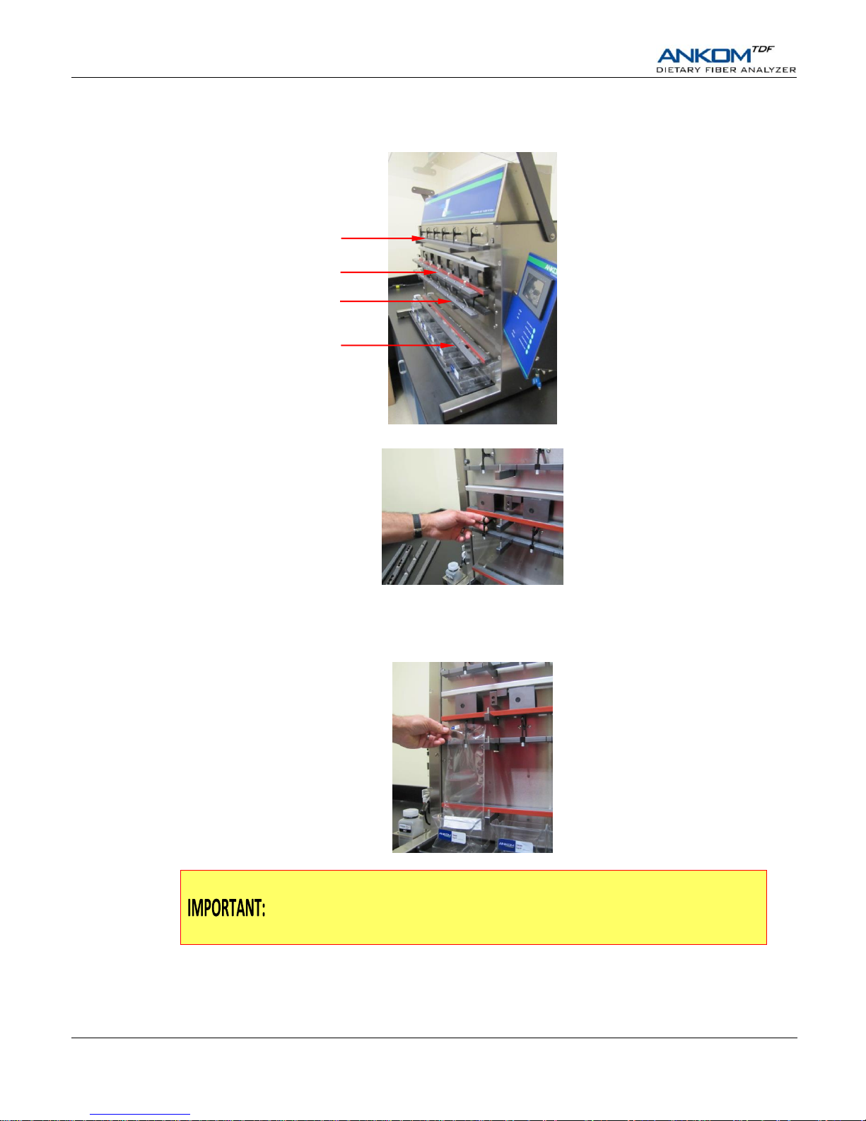
10.1 Remove Clamp Bars A, B, C, and D by lifting them off of the locator rods.
10.2 Gently pull the black SDF Delivery Nozzle out toward you.
10.3 Place a labeled and weighed SDF bag up underneath the SDF Delivery Nozzle so that the Delivery Nozzle is
inside the top part of the bag. Pull the bag up so that the top of the bag is about 35 mm (1.375 inches) above the
top of Clamp Bar C and return the Delivery Nozzle to its original position. This will hold the back of the bag in
place.
As part of normal operation, solution from the IDF bag will flow into the SDF bag.
Therefore, when installing the SDF filter bags it is very important to position them
high enough vertically so that at least 20 mm (0.75 inches) of the filter part of the
IDF bag can fit inside the top of the SDF bag.
Clamp Bar C
Clamp Bar D
Clamp Bar B
Clamp Bar A
Page 21
Operator’s Manual
Rev 9/20/18 pg. 21
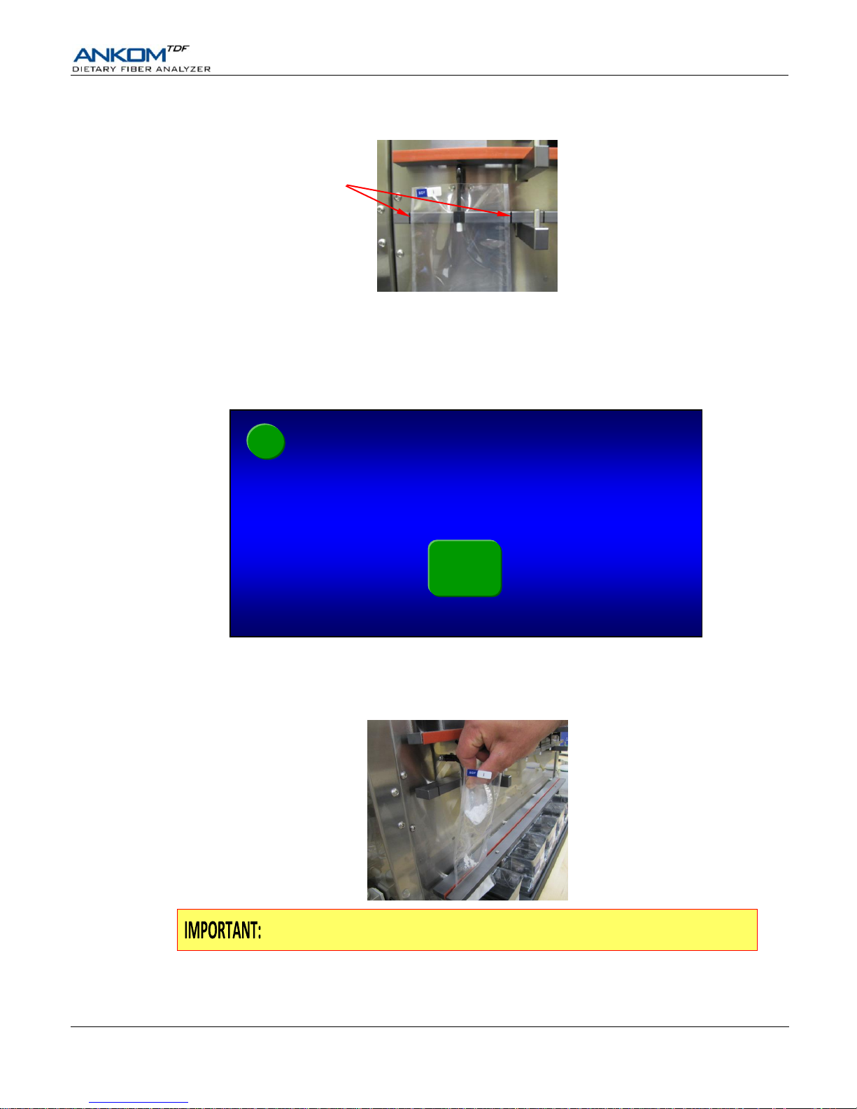
10.4 With the bag being held by the Delivery Nozzle, center it horizontally between the lines on the back part of
Clamp Bar C.
10.5 Repeat steps 10.2 – 10.4 for all six stations.
10.6 Re-install Clamp Bar D by setting it on the locator rods. Make sure the letter is on the top of the bar and the
rubber material is facing in toward the instrument.
10.7 Flatten the bags to remove any wrinkles.
10.8 With fingers away from the clamp bars, press the check mark () button on the Touch Screen Display to pinch
the bags just above the filter. The following screen will be displayed.
11. Add DE to the SDF filter bags on the ANKOM
TDF
Dietary Fiber Analyzer.
11.1 Open the top of the SDF bag and add a weigh tin of DE to the bag by folding the tin and then dipping it down into
the bag below the tip of the Delivery Nozzle.
When adding DE to the filter bags it is very important to keep it below the tip of
the Delivery Nozzle so that the DE material can be properly rinsed.
11.2 Rinse the tin with no more than 3 ml of 78% EtOH to ensure complete transfer.
11.3 Repeat steps 11.1 – 11.2 for all six stations.
Diatomaceous Earth
added in SDF Bags?
AOAC
991.43
IDF/SDF
←
Centering Lines
Page 22
Operator’s Manual
pg. 22 Rev 9/20/18
11.4 Press the check mark () button on the Touch Screen Display. The following screen will be displayed.
After you confirm that the DE is added, the Clamp Bar D button on the Control
Panel is disabled until the SDF process completes.
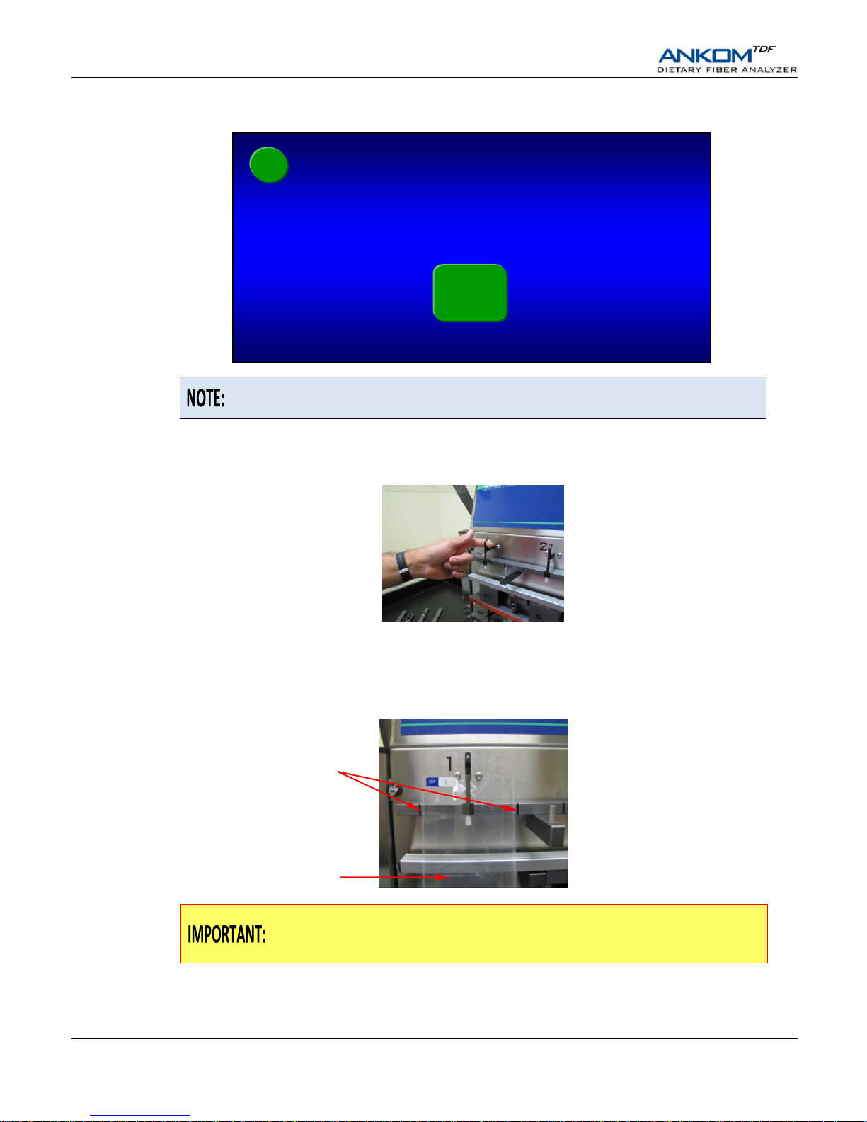
12. Install IDF filter bags on the ANKOM
TDF
Dietary Fiber Analyzer.
12.1 Gently pull the black IDF Delivery Nozzle out toward you.
12.2 Place a labeled and weighed IDF bag up underneath the Delivery Nozzle so that the Delivery Nozzle is inside the
top part of the bag. Pull the bag up so that the top of the filter part of the IDF bag is just below the bottom of
Clamp Bar B and return the Delivery Nozzle to its original position. This will hold the back of the bag in place.
12.3 With the bag held by the Delivery Nozzle, center it horizontally between the Centering Lines on the back part of
Clamp Bar A.
For proper mixing during the IDF process the IDF bags must be horizontally
centered over the Heating Paddles and between the Centering Lines on the back
part of Clamp Bar A.
IDF Bags (and clamp bar B) installed?
←
AOAC
991.43
IDF/SDF
Centering Lines
Heating Paddle
Page 23
Operator’s Manual
Rev 9/20/18 pg. 23
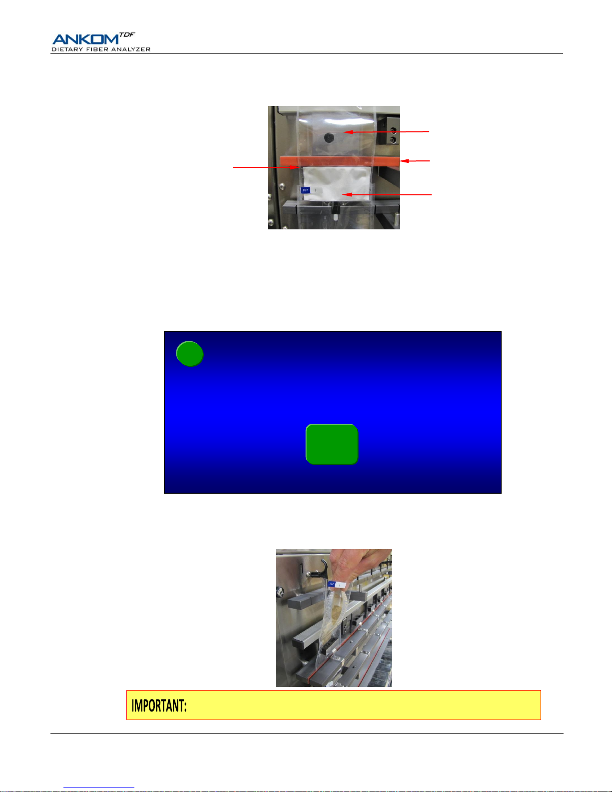
12.4 Place at least 20 mm (0.75 inches) of the filter section of the IDF bag inside the top of the SDF bag to allow for
the flow of liquid into the SDF bag after the IDF process is complete.
12.5 Repeat steps 12.1 – 12.4 for all six stations.
12.6 Re-install Clamp Bar B by setting it on the locator rods. Make sure the letter is on the top of the bar and the
rubber material is facing in toward the instrument.
12.7 Flatten the IDF bags to remove any wrinkles.
12.8 With fingers away from the clamp bars, press the check mark () button on the Touch Screen Display to pinch
the IDF bags just above the filter. The mixing pads will make contact with the bags when Clamp Bar B pinches
the IDF bags. The following screen will be displayed.
13. Add samples to the IDF bags.
13.1 Open the top of the IDF bag and transfer the sample from a weigh tin into the IDF bag by folding the tin and then
dipping it down into the bag below the tip of the Delivery Nozzle.
When adding sample to the filter bags it is very important to keep it below the tip
of the Delivery Nozzle so that it can be properly rinsed.
Samples in IDF Bags?
←
AOAC
991.43
IDF/SDF
Clamp Bar B
Top part of the filter is
positioned just below the
bottom of Clamp Bar B
20 mm (0.75 inches) of
the IDF filter inside the
top of the SDF bag
Heating Paddle
Page 24
Operator’s Manual
pg. 24 Rev 9/20/18
13.2 Rinse the tin with no more than 3 ml of Distilled Water to ensure complete transfer.
13.3 Repeat steps 13.1 – 13.2 for all IDF stations.
13.4 Re-install Clamp Bar A by setting it on the locator rods. Make sure the letter is on the top of the bar and the
rubber material is facing in toward the instrument.
13.5 Press the check mark () button on the Touch Screen Display. The following screen will be displayed.
13.6 Make sure that all clamp bars are installed with the letter on the top of the bar and the rubber material facing in
toward the instrument. Press the check mark () button on the Touch Screen Display. The following screen will
be displayed.
14. Hook the front of each SDF bag in place.
14.1 Secure the SDF filter bags in place with the hooks located on the front part of Clamp Bar C.
Hooking the bags in place will put a physical hole in the front of each SDF bag.
14.2 Press the check mark () button on the Touch Screen Display. If you ran a method other than 991.43 prior to this
run, the following screen will be displayed.
Front of SDF Bags hooked to clamp bar C?
←
AOAC
991.43
IDF/SDF
All remaining clamp bars installed?
←
AOAC
991.43
IDF/SDF
Hook on front part of
Clamp Bar C
Page 25
Operator’s Manual
Rev 9/20/18 pg. 25
15. Verify that the fluid containers have the correct fluids for this procedure.
Verify that the fluid supply containers are configured according to the screen above and press the check mark () button.
The following screen will be displayed.
16. Fill fluid containers.
To ensure that you have enough fluids to run a complete IDF/SDF procedure, you must begin with fluid levels above the
Minimum Level lines on the chemical containers and at least 15 ml of each enzyme. Add fluids and enzymes as
necessary.
Do NOT leave the enzyme ports on the instrument open to the air or the enzymes
in the valves may dry up and plug the ports.
With all fluid containers filled to the proper levels, press the check mark () button on the Touch Screen Display. The
following screen will be displayed.
Nitrogen supply ON?
←
AOAC
991.43
IDF/SDF
Fluid levels correct?
←
AOAC
991.43
IDF/SDF
Amylase -> Amylase
AMG -> AMG
HCL -> HCL
Buffer -> Mes Tris Buffer
←
Check supply containers
AOAC
991.43
IDF/SDF
Page 26
Operator’s Manual
pg. 26 Rev 9/20/18
17. Connect the Nitrogen Supply to the instrument and turn on.
Make sure the Nitrogen supply in your lab is connected to the instrument and turned on. The pressure gauges on the
instrument should show 50-55 psi on the left and about 4 psi on the right.
Press the check mark () button on the Touch Screen Display. The following screen will be displayed.
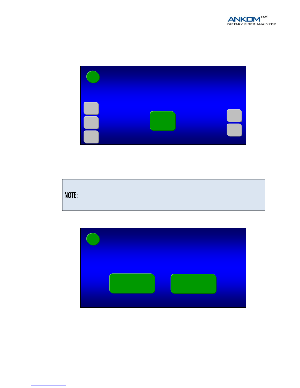
18. Set filter times (in minutes).
Because different samples take different amounts of time to filter, the above screen allows you to set your filter times. To
change any of the times shown on the screen, press the specific gray button. A number pad will be displayed that will
allow you to enter the time that you want. The times you enter will remain until you change them again.
The initial filter times shown when you first run the instrument are based on factory
experience. During filtration the computer allows you to bypass the filter time if
you notice the filtering is complete. The computer also allows you to add time
during filtering if needed (see the “Status Screen” section of this manual for more
detail).
When all of the times shown on the screen are what you want, press the check mark () button on the Touch Screen
Display. The following screen will be displayed.
19. Set the Manual pH Check.
If you plan to check the pH after the required HCl is added (during the IDF process), press the Yes button on the screen
above. Otherwise, press the No button. The following screen will be displayed.
Check pH manually?
←
Yes
No
AOAC
991.43
IDF/SDF
Filter minutes OK?
←
After release
After water rinses
After EtOH rinses
After release
After EtOH rinses
5.0
1.0
1.0
10.0
3.0
IDF
SDF
(Press button with number to change)
AOAC
991.43
IDF/SDF
Page 27
Operator’s Manual
Rev 9/20/18 pg. 27
20. Start the instrument.
The instrument is now completely set up and ready to automatically run the IDF/SDF procedure. Press the START button
to begin. At the beginning of each new run, the instrument automatically runs a tube integrity test.
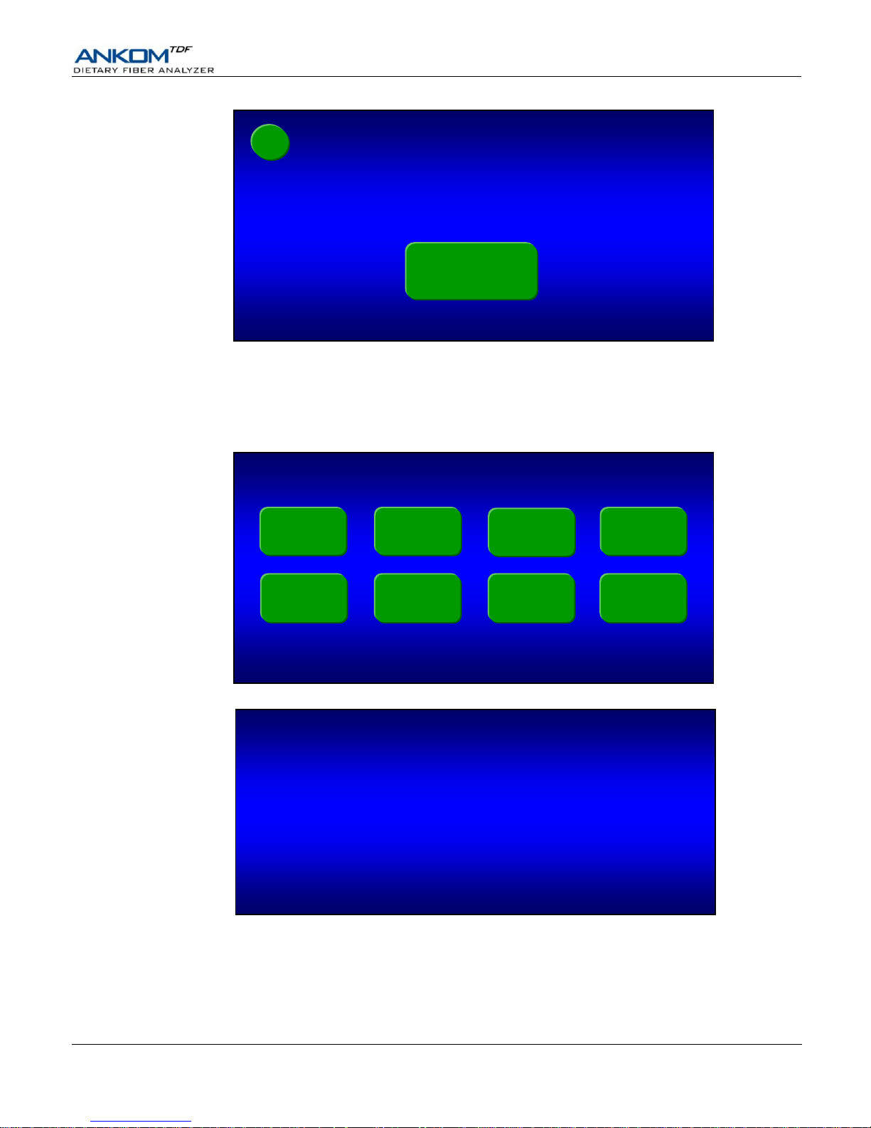
For the first run after a power-up cycle, or for the first run after the instrument has been idle for twelve hours, the
following screen will be displayed.
If the fluid lines are already charged properly, or when the line charge is complete, the following screen will be displayed.
When the tube integrity check is complete, the instrument will automatically execute the IDF/SDF procedure stopping
only for faults, aborts, and manual pH measurement (if enabled). The Status screen will show actions and faults as they
occur during the automatic operation.
Testing pump tubing.
Please wait..........
Initializing lines…
Amylase
EtOH78
Protease
EtOH95
AMG
Water
HCL
Buffer
Vacuum xx.x
cur: - x.x
max: - x.x
Press START to begin
←
START
AOAC
991.43
IDF/SDF
Page 28

Operator’s Manual
pg. 28 Rev 9/20/18
21. Manually measure pH.
One of the questions you are asked before starting the automated procedure is: “Check pH manually?” If you answered
“Yes” to this question, the instrument will stop after adding the required HCl, open Clamp Bar A, display the screen
below, and make a sound to remind you to manually measure pH and adjust to 4.0 - 4.7 if necessary.
When measuring pH, use a probe that can be easily rinsed (with Distilled Water) to
avoid loss of sample. If you add 0.5N HCl or base to adjust the pH, you must mix
the solution in order to get an accurate pH reading. To manually mix the solution,
press the outside of the bag with your fingers just above Clamp Bar B multiple
times.
When you have completed the pH measurement process, press the Continue button on the Status screen. You will see
“COMPLETE” next to “pH required?” in the upper left corner of the screen.
22. Rinse the IDF filter bags with acetone.
After the instrument has completed an IDF process the IDF residue that has been collected in the IDF bag must be
manually rinsed twice with acetone. It is recommended that you use an ANKOM TDF51 Rinse Stand (sold separately) for
rinsing filter bags with acetone.
To rinse the IDF filter bags with acetone using the ANKOM TDF51 Rinse Stand, follow the steps below.
22.1 Remove the IDF bags from the instrument.
22.2 Place the bags on the Rinse Stand by sliding the back part of each bag under the
pinch mechanism. Keep the top of the bag open.
22.3 Using a wash bottle, squirt acetone completely around the inside polypropylene
surfaces of each bag, making sure that all residue on the surfaces is rinsed down
into the filter.
22.4 Repeat step 22.3 so that each bag gets rinsed a total of two times.
22.5 Allow acetone to evaporate from the bags.
Hazardous Materials – Do NOT heat seal or place bags in an oven until all
acetone has evaporated.
Status
Overall Progress
Action in progress
IDF
Time remaining:
Amylase/AMG Phase
XX:XX:XX
Time remaining: XX:XX:XX
SDF
Time remaining:
XX:XX:XX
pH required?
Display
Temps/Pressures
YES
IDF
ABORT
PAUSE
SDF
ABORT
AOAC
991.43
IDF/SDF
Vacuum xx.x
cur: - x.x
max: - x.x
Check pH
then press continue
xx:xx:xx
Continue
Page 29
Operator’s Manual
Rev 9/20/18 pg. 29
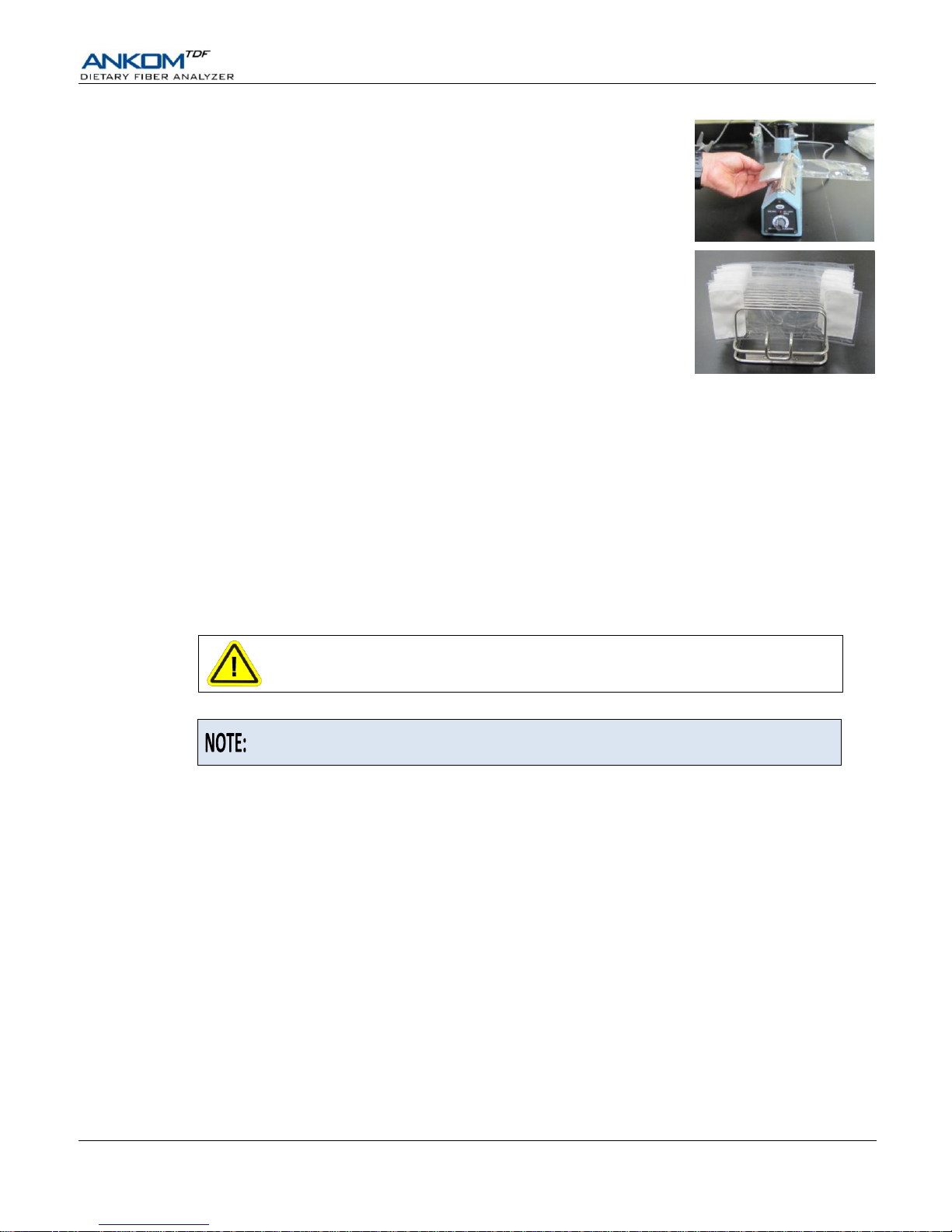
22.6 With your Heat Sealer set between 3 and 4 (settings may vary depending on the
heat sealer and the power source), press the Heat Sealer arm down. Hold the
arm down for 3 to 4 seconds after the light goes out to seal each bag just
above the filter. This keeps all residue contained to the filter area while handling
the bags.
22.7 Place each bag in the Drying Rack.
23. Rinse the SDF filter bags with acetone.
After the instrument has completed an SDF process the SDF residue that has been collected in the SDF bag must be
manually rinsed with acetone. It is recommended that you use an ANKOM TDF51 Rinse Stand for rinsing filter bags with
acetone.
To rinse the SDF filter bags with acetone using the ANKOM TDF51 Rinse Stand, follow the steps below.
23.1 Remove the SDF bags from the instrument.
23.2 Place the bags on the Rinse Stand by sliding the back part of each bag under the pinch mechanism. Keep the top
of the bag open.
23.3 Using a wash bottle, squirt acetone completely around the inside polypropylene surfaces of each bag, making sure
that all residue on the surfaces is rinsed down into the filter.
23.4 Repeat step 23.3 so that each bag gets rinsed a total of two times.
23.5 Allow acetone to evaporate from the bags.
Hazardous Materials – Do NOT heat seal or place bags in an oven until all
acetone has evaporated.
23.6 Seal each bag just above the filter to keep all residue contained to the filter area while handling the bags.
Sealing each bag as close to the filter as possible allows you to trim the maximum
amount of polypropylene from the bag before determining the protein content.
23.7 Place each bag in the Drying Rack.
24. Dry the IDF and SDF filter bags.
24.1 Make sure your oven is 105°C at the location where the bags will be placed.
24.2 Place the Drying Rack with the filter bags in the oven and dry to constant weight (about 90 minutes).
24.3 When dry, remove all IDF and SDF filter bags from the oven and place them in separate desiccant pouches.
25. Weigh the IDF residue.
25.1 Remove only one IDF filter bag from the desiccant pouch at a time.
25.2 Roll or fold the bag, place it in a tared Bag Weigh Holder (BWH), and place the BWH in the center of a balance.
25.3 Record the weight of the filter bag.
25.4 Repeat steps 25.1 – 25.3 for each IDF filter bag used in the fiber analysis.
26. Weigh the SDF residue.
26.1 Remove only one SDF filter bag from the desiccant pouch at a time.
26.2 Roll or fold the bag, place it in a tared Bag Weigh Holder (BWH), and place the BWH in the center of a balance.
26.3 Record the weight of the filter bag.
26.4 Repeat steps 26.1 – 26.3 for each SDF filter bag used in the fiber analysis.
Page 30

Operator’s Manual
pg. 30 Rev 9/20/18
27. Determine the Protein content within the IDF and SDF residue.
See the “Protein Determination” section of this manual for recommended procedures.
28. Determine the Ash content within the IDF and SDF residue.
See the “Ash Determination” section of this manual for recommended procedures.
29. Calculate the % IDF value.
% IDF = [(R1 + R2)/2] - P - A - B
(M1 + M2)/2
=
[(( fF1 - fS1) + ( fF2 - fS2))/2] - P - A - B
(M1 + M2)/2
Where:
M1, M2
=
Original wt of duplicate samples adjusted for pre-treatment fat and sugar losses (g)
R1, R2
=
Residue for duplicate samples (g)
fF
=
Final Filter Bag with residue (g)
fS
=
Initial Filter Bag (g)
P =
Protein of residue and bag (g)
A
=
Ash of residue and bag (g)
B
=
Blank (g)
= [(BR1 + BR2)/2] - PB - AB
= [((f
BF1
- f
BS1
) + (f
BF2
- f
BS2
))/2] - PB - AB
BR1, BR2
=
Residue for duplicate blanks (g)
fBF
=
Final Blank Filter Bag (g)
fBS
=
Initial Blank Filter Bag (g)
PB
=
Protein of Blank Filter Bag (g)
AB
=
Ash of Blank Filter Bag (g)
30. Calculate the % SDF value.
% SDF
=
[(R1 + R2)/2] - P - A - B
(M1 + M2)/2
=
[(( fF1 - fS1 - D1) + ( fF2 - fS2 - D2))/2] - P1 - (A2 - D2) - B
(M1 + M2)/2
Where:
M1, M2
=
Original wt of duplicate samples adjusted for pre-treatment fat and sugar losses (g)
R1, R2
=
Residue for duplicate samples (g)
fF
=
Final Filter Bag with residue (g)
fS
=
Initial Filter Bag (g)
D =
Original wt of Diatomaceous Earth (g)
P =
Protein of residue and bag (g)
A
=
Ash of residue and bag (g)
B
=
Blank (g)
= [(BR1 + BR2)/2] - PB - (AB - DB)
= [((f
BF1
- f
BS1
- DB1) + (f
BF2
- f
BS2
- DB2))/2] - PB1 - (AB2 - DB2)
BR1, BR2
=
Residue for duplicate blanks (g)
fBF
=
Final Blank Filter Bag (g)
fBS
=
Initial Blank Filter Bag (g)
PB
=
Protein of Blank Filter Bag (g)
AB
=
Ash of Blank Filter Bag (g)
DB
=
Original wt of Diatomaceous Earth in Blank Filter Bag (g)
31. Calculate the % TDF value by adding the % IDF and % SDF values.
X 100
X 100
X 100
X 100
Page 31

Operator’s Manual
Rev 9/20/18 pg. 31
TDF Analysis (AOAC 991.43)
A TDF analysis directly measures the amount of TDF within a given sample without separately measuring the IDF and SDF
fractions. TDF can be determined using multiple methods. This section describes the procedure for using the ANKOM
TDF
Dietary Fiber Analyzer to determine TDF based on the AOAC 991.43 method.
This analysis requires an SDF filter bag (ANKOM DF-S) for the precipitation process and a non-filter IDF Flow-Thru bag
(ANKOM DF-FT) for the digestion process. When starting a new run, the ANKOM
TDF
Dietary Fiber Analyzer must have bags
installed at all stations (a total of twelve bags).
To enhance the productivity of your instrument, you can begin the IDF process of a
new run while the SDF process of a previous run is finishing. See the “Productivity
Enhancement” section of this manual for more details.
To perform a TDF analysis, follow the steps below.
1. Prepare chemicals and enzymes.
When using the ANKOM
TDF
Dietary Fiber Analyzer for the AOAC 991.43, AACC 32-07.01, and NMKL 129,2003
methods use the chemicals and enzymes referred to therein. See Appendix A of this manual for the list of chemicals and
enzymes and the instructions for how to prepare them for use in this instrument.
2. De-fat your samples as needed according to the official methods. See "Appendix C – De-fatting
Procedure" in this manual for an ANKOM procedure.
3. Label the bags using a Solvent Resistant Marker.
4. Prepare for data collection.
You will need a place to store the data collected during this analysis. For your convenience a CD titled “Calculation
Templates” was included with the instrument. This CD has data spreadsheets that can be used for this analysis. Please
read the “Instructions” tab in the MS-Excel file for information about the spreadsheets.
5. Weigh filter bags.
Using a Bag Weigh Holder is critical to eliminate the effects of static electricity
during the weighing process.
Roll or fold each bag and place it in a tared Bag Weigh Holder. Place the Bag Weigh Holder in the center of a balance
and record the weight.
Because different balances have different sensitivities, the Bag Weigh Holder
should be placed in the center of the balance for best results.
SDF Bag (longer bag with filter)
IDF Flow-thru Bag (shorter bag / no filter)
Page 32

Operator’s Manual
pg. 32 Rev 9/20/18
6. Weigh Diatomaceous Earth (DE).
DE is used during fiber analysis to enhance the flocculation and filtration of the SDF fraction. Place ca 1 g of DE in each
of six tared and numbered tins and record the weights.
7. Weigh Samples.
Place 0.50.05 g of sample in each of six tared and numbered tins and record the weights.
A larger sample (1.0 g) can be used if a larger aliquot is needed to improve
precision.
8. Turn the instrument power on.
When you turn the power on, the instrument will run through an initialization process and the Control Panel will turn on.
9. On the Touch Screen Display, select the instrument function you would like to perform.
The Control Panel on the ANKOM
TDF
Dietary Fiber Analyzer uses Touch Screen technology. To operate the instrument
you will press identified buttons on the Touch Screen Display and buttons below the screen.
When your instrument is initialized and ready to operate, the following screen will be displayed.
Although the instrument works in accordance with AACC and NMKL methods, the
Touch Screen Display only refers to the AOAC methods.
9.1 If this is the first time the instrument is being operated after being installed, or after sitting unused for a period of
time (see Appendix B), or after tubing was replaced, the lines must be charged to avoid a Vacuum Sensor Fault.
To charge the lines follow the steps below.
9.1.1 Press the Diagnostics button on the “Select a Function” screen. The following screen will be displayed.
Diagnostics
Touch Screen Display version: A.AA
SPLat controller software version: vX.XX dd-mm-yy
Pump Tube
Test
Expert Mode
Faults
Service
Mode
Clear IDF /
SDF lines
Digestion
Times
Heater Test
Temperatures
Pressures
Line Charge
Motor Test
Valve Test
Select a Function
AOAC 991.43
IDF/SDF
AOAC 985.29
TDF
Diagnostics
AOAC 991.43
TDF
AOAC 2001.03
TDF
←
Page 33

Operator’s Manual
Rev 9/20/18 pg. 33
9.1.2 Press the Line Charge button. The following screen will be displayed.
9.1.3 Press the ALL button to charge all of the lines. Each button will change color as the associated line is being
charged. All lines are charged when all of the buttons return to their original green color.
9.1.4 Press the back button twice. The following “Select a Function” screen will be displayed again.
9.2 Press the AOAC 991.43 TDF button. The following screen will be displayed.
Notice that the function you selected is now displayed in the top right corner of the screen and a back button
is displayed in the top left corner of the screen.
SDF Bags (and clamp bar D) installed?
←
AOAC
991.43
TDF
Select a Function
AOAC 991.43
IDF/SDF
AOAC 985.29
TDF
Diagnostics
AOAC 991.43
TDF
AOAC 2001.03
TDF
Line Charge
Amylase
Protease
AMG
HCl
EtOH78
EtOH95
Water
Buffer
ALL
Vacuum xx.x
cur: - x.x
max: - x.x
←
Page 34

Operator’s Manual
pg. 34 Rev 9/20/18
10. Install SDF filter bags on the ANKOM
TDF
Dietary Fiber Analyzer.
10.1 Remove Clamp Bars A, B, C, and D by lifting them off of the locator rods.
10.2 Gently pull the black SDF Delivery Nozzle out toward you.
10.3 Place a labeled and weighed SDF bag up underneath the SDF Delivery Nozzle so that the Delivery Nozzle is
inside the top part of the bag. Pull the bag up so that the top of the bag is about 35 mm (1.375 inches) above the
top of Clamp Bar C and return the Delivery Nozzle to its original position. This will hold the back of the bag in
place.
As part of normal operation, solution from the IDF Flow-thru bag will flow into the
SDF bag. Therefore, when installing the SDF filter bags it is very important to
position them high enough vertically so that at least 20 mm (0.75 inches) of the
bottom of the IDF Flow-thru bag can fit inside the top of the SDF bag.
Clamp Bar C
Clamp Bar D
Clamp Bar B
Clamp Bar A
Page 35

Operator’s Manual
Rev 9/20/18 pg. 35
10.4 With the bag being held by the Delivery Nozzle, center it horizontally between the lines on the back part of
Clamp Bar C.
10.5 Repeat steps 10.2 – 10.4 for all six stations.
10.6 Re-install Clamp Bar D by setting it on the locator rods. Make sure the letter is on the top of the bar and the
rubber material is facing in toward the instrument.
10.7 Flatten the bags to remove any wrinkles.
10.8 With fingers away from the clamp bars, press the check mark () button on the Touch Screen Display to pinch
the bags. The following screen will be displayed.
11. Add DE to the SDF filter bags on the ANKOM
TDF
Dietary Fiber Analyzer.
11.1 Open the top of the SDF bag and add a weigh tin of DE to the bag by folding the tin and then dipping it down into
the bag below the tip of the Delivery Nozzle.
When adding DE to the filter bags it is very important to keep it below the tip of
the Delivery Nozzle so that the DE material can be properly rinsed.
11.2 Rinse the tin with no more than 3 ml of 78% EtOH to ensure complete transfer.
11.3 Repeat steps 11.1 – 11.2 for all six stations.
Diatomaceous Earth
added in SDF Bags?
←
AOAC
991.43
TDF
Centering Lines
Page 36

Operator’s Manual
pg. 36 Rev 9/20/18
11.4 Press the check mark () button on the Touch Screen Display. The following screen will be displayed.
After you confirm that the DE is added, the Clamp Bar D button on the Control
Panel is disabled until the SDF process completes.
12. Install IDF Flow-thru bags on the ANKOM
TDF
Dietary Fiber Analyzer.
12.1 Gently pull the black IDF Delivery Nozzle out toward you.
12.2 Place a labeled IDF Flow-Thru bag up underneath the Delivery Nozzle so that the Delivery Nozzle is inside the
top part of the bag. Pull the bag up so that the top of the bag is about 35 mm (1.375 inches) above the top of
Clamp Bar A and return the Delivery Nozzle to its original position. This will hold the back of the bag in place.
12.3 With the bag held by the Delivery Nozzle, center it horizontally between the Centering Lines on the back part of
Clamp Bar A.
For proper mixing during the IDF process the IDF Flow-thru bags must be
horizontally centered over the Heating Paddles and between the Centering Lines on
the back part of Clamp Bar A.
IDF Flow-Thru Bags (and clamp bar B) installed?
←
AOAC
991.43
TDF
Centering Lines
Heating Paddle
Page 37

Operator’s Manual
Rev 9/20/18 pg. 37
12.4 Place at least 20 mm (0.75 inches) of the bottom of the IDF Flow-Thru bag inside the top of the SDF bag to allow
for the flow of solution into the SDF bag after the digestion process is complete.
12.5 Repeat steps 12.1 – 12.4 for all six stations.
12.6 Re-install Clamp Bar B by setting it on the locator rods. Make sure the letter is on the top of the bar and the
rubber material is facing in toward the instrument.
12.7 Flatten the IDF Flow-Thru bags to remove any wrinkles.
12.8 With fingers away from the clamp bars, press the check mark () button on the Touch Screen Display to pinch
the IDF Flow-Thru bags. The mixing pads will make contact with the bags when Clamp Bar B pinches the IDF
Flow-Thru bags. The following screen will be displayed.
13. Add samples to the IDF Flow-thru bags.
13.1 Open the top of the IDF Flow-thru bag and transfer the sample from a weigh tin into the bag by folding the tin
and then dipping it down into the bag below the tip of the Delivery Nozzle.
When adding sample to the IDF Flow-thru bags it is very important to keep it
below the tip of the Delivery Nozzle so that it can be properly rinsed.
13.2 Rinse the tin with no more than 3 ml of Distilled Water to ensure complete transfer.
Samples in IDF Flow-Thru Bags?
←
AOAC
991.43
TDF
20 mm (0.75 inches) of the
IDF Flow-Thru bag inside the
top of the SDF bag
Heating Paddle
Page 38

Operator’s Manual
pg. 38 Rev 9/20/18
13.3 Repeat steps 13.1 – 13.2 for all IDF stations.
13.4 Re-install Clamp Bar A by setting it on the locator rods. Make sure the letter is on the top of the bar and the
rubber material is facing in toward the instrument.
13.5 Press the check mark () button on the Touch Screen Display. The following screen will be displayed.
13.6 Make sure that all clamp bars are installed with the letter on the top of the bar and the rubber material facing in
toward the instrument. Press the check mark () button on the Touch Screen Display. The following screen will
be displayed.
14. Hook the front of each SDF bag in place.
14.1 Secure the SDF filter bags in place with the hooks located on the front part of Clamp Bar C.
Hooking the bags in place will put a physical hole in the front of each SDF bag.
14.2 Press the check mark () button on the Touch Screen Display. If you ran a method other than 991.43 prior to this
run, the following screen will be displayed.
Front of SDF Bags hooked to clamp bar C?
←
AOAC
991.43
TDF
All remaining clamp bars installed?
←
AOAC
991.43
TDF
Hook on front part of
Clamp Bar C
Page 39

Operator’s Manual
Rev 9/20/18 pg. 39
15. Verify that the fluid containers have the correct fluids for this procedure.
Verify that the fluid supply containers are configured according to the screen above and press the check mark () button.
The following screen will be displayed.
16. Fill fluid containers.
To ensure that you have enough fluids to run a complete TDF procedure, you must begin with fluid levels above the
Minimum Level lines on the chemical containers and at least 15 ml of each enzyme. Add fluids and enzymes as
necessary.
Do NOT leave the enzyme ports on the instrument open to the air or the enzymes
in the valves may dry up and plug the ports.
With all fluid containers filled to the proper levels, press the check mark () button on the Touch Screen Display. The
following screen will be displayed.
Nitrogen supply ON?
←
AOAC
991.43
TDF
Fluid levels correct?
←
AOAC
991.43
TDF
Amylase -> Amylase
AMG -> AMG
HCL -> HCL
Buffer -> Mes Tris Buffer
←
Check supply containers
AOAC
991.43
TDF
Page 40

Operator’s Manual
pg. 40 Rev 9/20/18
17. Connect the Nitrogen Supply to the instrument and turn on.
Make sure the Nitrogen supply in your lab is connected to the instrument and turned on. The pressure gauges on the
instrument should show 50-55 psi on the left and about 4 psi on the right.
Press the check mark () button on the Touch Screen Display. The following screen will be displayed.
18. Set filter times (in minutes).
Because different samples take different amounts of time to filter, the above screen allows you to set your filter times. To
change any of the times shown on the screen, press the specific gray button. A number pad will be displayed that will
allow you to enter the time that you want. The times you enter will remain until you change them again.
The initial filter times shown when you first run the instrument are based on factory
experience. During filtration the computer allows you to bypass the filter time if
you notice the filtering is complete. The computer also allows you to add time
during filtering if needed (see the “Status Screen” section of this manual for more
detail).
When all of the times shown on the screen are what you want, press the check mark () button on the Touch Screen
Display. The following screen will be displayed.
19. Set the Manual pH Check.
If you plan to check the pH after the required HCl is added (during the IDF process), press the Yes button on the screen
above. Otherwise, press the No button. The following screen will be displayed.
Check pH manually?
←
Yes
No
AOAC
991.43
TDF
←
After release
After EtOH rinses
10.0
3.0
SDF Filter minutes OK?
(Press button with number to change)
AOAC
991.43
TDF
Page 41

Operator’s Manual
Rev 9/20/18 pg. 41
20. Start the instrument.
The instrument is now completely set up and ready to automatically run the TDF procedure. Press the START button to
begin. At the beginning of each new run, the instrument automatically runs a tube integrity test.
For the first run after a power-up cycle, or for the first run after the instrument has been idle for twelve hours, the
following screen will be displayed.
If the fluid lines are already charged properly, or when the line charge is complete, the following screen will be displayed.
When the tube integrity check is complete, the instrument will automatically execute the TDF procedure stopping only for
faults, aborts, and manual pH measurement (if enabled). The Status screen will show actions and faults as they occur
during the automatic operation.
Testing pump tubing.
Please wait..........
Initializing lines…
Amylase
EtOH78
Protease
EtOH95
AMG
Water
HCL
Buffer
Vacuum xx.x
cur: - x.x
max: - x.x
Press START to begin
←
START
AOAC
991.43
TDF
Page 42

Operator’s Manual
pg. 42 Rev 9/20/18
21. Manually measure pH.
One of the questions you are asked before starting the automated procedure is: “Check pH manually?” If you answered
“Yes” to this question, the instrument will stop after adding the required HCl, open Clamp Bar A, display the screen
below, and make a sound to remind you to manually measure pH and adjust to 4.0 - 4.7 if necessary.
When measuring pH use a probe that can be easily rinsed (with Distilled Water) to
avoid loss of sample. If you add 0.5N HCl or base to adjust the pH, you must mix
the solution in order to get an accurate pH reading. To manually mix the solution,
press the outside of the bag with your fingers just above Clamp Bar B multiple
times.
When you have completed the pH measurement process, press the Continue button on the Status screen. You will see
“COMPLETE” next to “pH required?” in the upper left corner of the screen.
22. Make sure that each sample is completely rinsed down into the SDF filter bags (as needed).
Since the IDF Flow-thru bags are not weighed before and after the process, it is important to make sure that each sample
gets rinsed down into the SDF filter bag when the digestion process is complete.
If you notice sample sticking to an IDF Flow-thru bag, use 78% EtOH in a wash bottle to rinse as needed.
23. Rinse the SDF filter bags with acetone.
After the instrument has completed a TDF process the TDF residue that has been collected in the SDF bag must be
manually rinsed with acetone. It is recommended that you use an ANKOM TDF51 Rinse Stand (sold separately) for
rinsing filter bags with acetone.
To rinse the SDF filter bags with acetone using the ANKOM TDF51 Rinse Stand, follow the
steps below.
23.1 Remove the SDF bags from the instrument.
23.2 Place the bags on the Rinse Stand by sliding the back part of the bag under the pinch
mechanism. Keep the top of the bag open.
23.3 Using a wash bottle, squirt acetone completely around the inside polypropylene
surfaces of each bag, making sure that all residue on the surfaces is rinsed down into
the filter.
23.4 Repeat step 23.3 so that each bag gets rinsed a total of two times.
23.5 Allow acetone to evaporate from the bags.
Hazardous Materials – Do NOT heat seal or place bags in an oven until all
acetone has evaporated.
Status
Overall Progress
Action in progress
IDF
Time remaining:
Amylase/AMG Phase
XX:XX:XX
Time remaining: XX:XX:XX
SDF
Time remaining:
XX:XX:XX
pH required?
Display
Temps/Pressures
YES
IDF
ABORT
PAUSE
SDF
ABORT
AOAC
991.43
TDF
Vacuum xx.x
cur: - x.x
max: - x.x
Check pH
then press continue
xx:xx:xx
Continue
Page 43

Operator’s Manual
Rev 9/20/18 pg. 43
23.6 With your Heat Sealer set between 3 and 4 (settings may vary depending on the heat
sealer and the power source), press the Heat Sealer arm down. Hold the arm down for
3 to 4 seconds after the light goes out to seal each bag just above the filter. This keeps
all residue contained to the filter area while handling the bags.
23.7 Place each bag in the Drying Rack.
24. Dry the SDF filter bags.
24.1 Make sure your oven is 105°C at the location where the bags will be placed.
24.2 Place the Drying Rack with the filter bags in the oven and dry to constant weight (about 90 minutes).
24.3 When dry, remove all SDF filter bags from the oven and place them in a desiccant pouch to cool.
25. Weigh the TDF residue.
25.1 Remove one SDF filter bag from the desiccant pouch.
25.2 Roll or fold the bag, place it in a tared Bag Weigh Holder (BWH), and place the BWH in the center of a balance.
25.3 Record the weight of the filter bag.
25.4 Repeat steps 25.1 – 25.3 for each SDF filter bag used in the fiber analysis.
26. Determine the Protein content within the TDF residue.
See the “Protein Determination” section of this manual for recommended procedures.
27. Determine the Ash content within the TDF residue.
See the “Ash Determination” section of this manual for recommended procedures.
28. Calculate the % TDF value.
% TDF
=
[(R1 + R2)/2] - P - A - B
(M1 + M2)/2
=
[(( fF1 - fS1 - D1) + ( fF2 - fS2 - D2))/2] - P1 - (A2 - D2) - B
(M1 + M2)/2
Where:
M1, M2
=
Original wt of duplicate samples adjusted for pre-treatment fat and sugar losses (g)
R1, R2
=
Residue for duplicate samples (g)
fF
=
Final Filter Bag with residue (g)
fS
=
Initial Filter Bag (g)
D =
Original wt of Diatomaceous Earth (g)
P =
Protein of residue and bag (g)
A
=
Ash of residue and bag (g)
B
=
Blank (g)
= [(BR1 + BR2)/2] - PB - (AB - DB)
= [((f
BF1
- f
BS1
- DB1) + (f
BF2
- f
BS2
- DB2))/2] - PB1 - (AB2 - DB2)
BR1, BR2
=
Residue for duplicate blanks (g)
fBF
=
Final Blank Filter Bag (g)
fBS
=
Initial Blank Filter Bag (g)
PB
=
Protein of Blank Filter Bag (g)
AB
=
Ash of Blank Filter Bag (g)
DB
=
Original wt of Diatomaceous Earth in Blank Filter Bag (g)
X 100
X 100
Page 44

Operator’s Manual
pg. 44 Rev 9/20/18
This page intentionally left blank
Page 45

Operator’s Manual
Rev 9/20/18 pg. 45
TDF Analysis (AOAC 985.29 / 2001.03)
A TDF analysis directly measures the amount of TDF within a given sample without separately measuring the IDF and SDF
fractions. TDF can be determined using multiple methods. This section describes the procedure for using the ANKOM
TDF
Dietary Fiber Analyzer to determine TDF based on the AOAC 985.29 and 2001.03 methods.
This analysis requires an SDF filter bag (ANKOM DF-S) for the precipitation process and a non-filter IDF Flow-Thru bag
(ANKOM DF-FT) for the digestion process. When starting a new run, the ANKOM
TDF
Dietary Fiber Analyzer must have bags
installed at all stations (a total of twelve bags).
To enhance the productivity of your instrument, you can begin the IDF process of a
new run while the SDF process of a previous run is finishing. See the “Productivity
Enhancement” section of this manual for more details.
To perform a TDF analysis, follow the steps below.
1. Prepare chemicals and enzymes.
When using the ANKOM
TDF
Dietary Fiber Analyzer for the AOAC 985.29 or 2001.03 methods use the chemicals and
enzymes referred to therein. See Appendix A of this manual for the list of chemicals and enzymes and the instructions for
how to prepare them for use in this instrument.
2. De-fat your samples as needed according to the official methods. See "Appendix C – De-fatting
Procedure" in this manual for an ANKOM procedure.
3. Label the bags using a Solvent Resistant Marker.
4. Prepare for data collection.
You will need a place to store the data collected during this analysis. For your convenience a CD titled “Calculation
Templates” is included with the instrument. This CD has TDF Data Spreadsheets that can be used for this analysis. Please
read the “Instructions” tab in the MS-Excel file for information about the spreadsheets.
5. Weigh filter bags.
Using a Bag Weigh Holder is critical to eliminate the effects of static electricity
during the weighing process.
Roll or fold each bag and place it in a tared Bag Weigh Holder. Place the Bag Weigh Holder in the center of a balance
and record the weight.
Because different balances have different sensitivities, the Bag Weigh Holder
should be placed in the center of the balance for best results.
SDF Bag (longer bag with filter)
IDF Flow-thru Bag (shorter bag / no filter)
Page 46

Operator’s Manual
pg. 46 Rev 9/20/18
6. Weigh Diatomaceous Earth (DE).
DE is used during fiber analysis to enhance the flocculation and filtration of the SDF fraction. Place ca 1 g of DE in each
of six tared and numbered tins and record the weights.
7. Weigh Samples.
Place 0.50.05 g of sample in each of six tared and numbered tins and record the weights.
A larger sample (1.0 g) can be used if a larger aliquot is needed to improve
precision.
8. Turn the instrument power on.
When you turn the power on, the instrument will run through an initialization process and the Control Panel will turn on.
9. On the Touch Screen Display, select the instrument function you would like to perform.
The Control Panel on the ANKOM
TDF
Dietary Fiber Analyzer uses Touch Screen technology. To operate the instrument
you will press identified buttons on the Touch Screen Display and buttons below the screen.
When your instrument is initialized and ready to operate, the following screen will be displayed.
Although the instrument works in accordance with AACC and NMKL methods, the
Touch Screen Display only refers to the AOAC methods.
9.1 If this is the first time the instrument is being operated after being installed, or after sitting unused for a period of
time (see Appendix B), or after tubing was replaced the lines must be charged to avoid a Vacuum Sensor Fault. To
charge the lines follow the steps below.
9.1.1 Press the Diagnostics button on the “Select a Function” screen. The following screen will be displayed.
Diagnostics
Touch Screen Display version: A.AA
SPLat controller software version: vX.XX dd-mm-yy
Pump Tube
Test
Expert Mode
Faults
Service
Mode
Clear IDF /
SDF lines
Digestion
Times
Heater Test
Temperatures
Pressures
Line Charge
Motor Test
Valve Test
Select a Function
AOAC 991.43
IDF/SDF
AOAC 985.29
TDF
Diagnostics
AOAC 991.43
TDF
AOAC 2001.03
TDF
←
Page 47

Operator’s Manual
Rev 9/20/18 pg. 47
9.1.2 Press the Line Charge button. The following screen will be displayed.
9.1.3 Press the ALL button to charge all of the lines. Each button will change color as the associated line is being
charged. All lines are charged when all of the buttons return to their original green color.
9.1.4 Press the back button twice. The following “Select a Function” screen will be displayed again.
9.2 Press either the AOAC 985.29 TDF button or the AOAC 2001.03 TDF button depending on the method you're doing.
One of the following screens will be displayed.
Notice that the function you selected is now displayed in the top right corner of the screen and a back button
is displayed in the top left corner of the screen.
←
SDF Bags (and clamp bar D) installed?
AOAC
2001.03
TDF
←
SDF Bags (and clamp bar D) installed?
AOAC
985.29
TDF
Select a Function
AOAC 991.43
IDF/SDF
AOAC 985.29
TDF
Diagnostics
AOAC 991.43
TDF
AOAC 2001.03
TDF
Line Charge
Amylase
Protease
AMG
HCl
EtOH78
EtOH95
Water
Buffer
ALL
Vacuum xx.x
cur: - x.x
max: - x.x
←
Page 48

Operator’s Manual
pg. 48 Rev 9/20/18
10. Install SDF filter bags on the ANKOM
TDF
Dietary Fiber Analyzer.
10.1 Remove Clamp Bars A, B, C, and D by lifting them off of the locator rods.
10.2 Gently pull the black SDF Delivery Nozzle out toward you.
10.3 Place a labeled and weighed SDF bag up underneath the SDF Delivery Nozzle so that the Delivery Nozzle is
inside the top part of the bag. Pull the bag up so that the top of the bag is about 35 mm (1.375 inches) above the
top of Clamp Bar C and return the Delivery Nozzle to its original position. This will hold the back of the bag in
place.
As part of normal operation, solution from the IDF Flow-thru bag will flow into the
SDF bag. Therefore, when installing the SDF filter bags it is very important to
position them high enough vertically so that at least 20 mm (0.75 inches) of the
bottom of the IDF Flow-thru bag can fit inside the top of the SDF bag.
Clamp Bar C
Clamp Bar D
Clamp Bar B
Clamp Bar A
Page 49

Operator’s Manual
Rev 9/20/18 pg. 49
10.4 With the bag being held by the Delivery Nozzle, center it horizontally between the lines on the back part of
Clamp Bar C.
10.5 Repeat steps 10.2 – 10.4 for all six stations.
10.6 Re-install Clamp Bar D by setting it on the locator rods. Make sure the letter is on the top of the bar and the
rubber material is facing in toward the instrument.
10.7 Flatten the bags to remove any wrinkles.
10.8 With fingers away from the clamp bars, press the check mark () button on the Touch Screen Display to pinch
the bags. One of the following screens will be displayed.
11. Add DE to the SDF filter bags on the ANKOM
TDF
Dietary Fiber Analyzer.
11.1 Open the top of the SDF bag and add a weigh tin of DE to the bag by folding the tin and then dipping it down into
the bag below the tip of the Delivery Nozzle.
When adding DE to the filter bags it is very important to keep it below the tip of
the Delivery Nozzle so that the DE material can be properly rinsed.
11.2 Rinse the tin with no more than 3 ml of 78% EtOH to ensure complete transfer.
11.3 Repeat steps 11.1 – 11.2 for all six stations.
←
Diatomaceous Earth
added in SDF Bags?
AOAC
2001.03
TDF
←
Diatomaceous Earth
added in SDF Bags?
AOAC
985.29
TDF
Centering Lines
AOAC
985.29
TDF
Page 50

Operator’s Manual
pg. 50 Rev 9/20/18
11.4 Press the check mark () button on the Touch Screen Display. One of the following screens will be displayed.
After you confirm that the DE is added, the Clamp Bar D button on the Control
Panel is disabled until the SDF process completes.
12. Install IDF Flow-thru bags on the ANKOM
TDF
Dietary Fiber Analyzer.
12.1 Gently pull the black IDF Delivery Nozzle out toward you.
12.2 Place a labeled IDF Flow-Thru bag up underneath the Delivery Nozzle so that the Delivery Nozzle is inside the
top part of the bag. Pull the bag up so that the top of the bag is about 35 mm (1.375 inches) above the top of
Clamp Bar A and return the Delivery Nozzle to its original position. This will hold the back of the bag in place.
12.3 With the bag held by the Delivery Nozzle, center it horizontally between the Centering Lines on the back part of
Clamp Bar A.
For proper mixing during the IDF process the IDF Flow-thru bags must be
horizontally centered over the Heating Paddles and between the Centering Lines on
the back part of Clamp Bar A.
←
IDF Flow-Thru Bags (and clamp bar B) installed?
AOAC
2001.03
TDF
←
IDF Flow-Thru Bags (and clamp bar B) installed?
AOAC
985.29
TDF
Centering Lines
Heating Paddle
Page 51

Operator’s Manual
Rev 9/20/18 pg. 51
12.4 Place at least 20 mm (0.75 inches) of the bottom of the IDF Flow-Thru bag inside the top of the SDF bag to allow
for the flow of solution into the SDF bag after the digestion process is complete.
12.5 Repeat steps 12.1 – 12.4 for all six stations.
12.6 Re-install Clamp Bar B by setting it on the locator rods. Make sure the letter is on the top of the bar and the
rubber material is facing in toward the instrument.
12.7 Flatten the IDF Flow-Thru bags to remove any wrinkles.
12.8 With fingers away from the clamp bars, press the check mark () button on the Touch Screen Display to pinch
the IDF Flow-Thru bags. The mixing pads will make contact with the bags when Clamp Bar B pinches the IDF
Flow-Thru bags. One of the following screens will be displayed.
13. Add samples to the IDF Flow-thru bags.
13.1 Open the top of the IDF Flow-thru bag and transfer the sample from a weigh tin into the bag by folding the tin
and then dipping it down into the bag below the tip of the Delivery Nozzle.
When adding sample to the IDF Flow-thru bags it is very important to keep it
below the tip of the Delivery Nozzle so that it can be properly rinsed.
13.2 Rinse the tin with no more than 3 ml of Distilled Water to ensure complete transfer.
←
Samples in IDF Flow-Thru Bags?
AOAC
2001.03
TDF
←
Samples in IDF Flow-Thru Bags?
AOAC
985.29
TDF
20 mm (0.75 inches) of the
IDF Flow-Thru bag inside the
top of the SDF bag
Heating Paddle
Page 52

Operator’s Manual
pg. 52 Rev 9/20/18
13.3 Repeat steps 13.1 – 13.2 for all IDF stations.
13.4 Re-install Clamp Bar A by setting it on the locator rods. Make sure the letter is on the top of the bar and the
rubber material is facing in toward the instrument.
13.5 Press the check mark () button on the Touch Screen Display. One of the following screens will be displayed.
13.6 Make sure that all clamp bars are installed with the letter on the top of the bar and the rubber material facing in
toward the instrument. Press the check mark () button on the Touch Screen Display. One of the following
screens will be displayed.
14. Hook the front of each SDF bag in place.
14.1 Secure the SDF filter bags in place with the hooks located on the front part of Clamp Bar C.
Hooking the bags in place will put a physical hole in the front of each SDF bag.
14.2 Press the check mark () button on the Touch Screen Display. If you ran a method other than 985.29 or 2001.03
prior to this run, one of the following screens will be displayed.
←
Front of SDF Bags hooked to clamp bar C?
AOAC
2001.03
TDF
←
Front of SDF Bags hooked to clamp bar C?
AOAC
985.29
TDF
←
All remaining clamp bars installed?
AOAC
2001.03
TDF
←
All remaining clamp bars installed?
AOAC
985.29
TDF
Hook on front part of
Clamp Bar C
Page 53

Operator’s Manual
Rev 9/20/18 pg. 53
15. Verify that the fluid containers have the correct fluids for this procedure.
Verify that the fluid supply containers are configured according to the screen above and press the check mark () button.
One of the following screens will be displayed.
16. Fill fluid containers.
To ensure that you have enough fluids to run a complete TDF procedure, you must begin with fluid levels above the
Minimum Level lines on the chemical containers and at least 15 ml of each enzyme. Add fluids and enzymes as
necessary.
Do NOT leave the enzyme ports on the instrument open to the air or the enzymes
in the valves may dry up and plug the ports.
With all fluid containers filled to the proper levels, press the check mark () button on the Touch Screen Display. One of
the following screens will be displayed.
AOAC
2001.03
TDF
←
Nitrogen supply ON?
AOAC
985.29
TDF
←
Nitrogen supply ON?
←
Fluid levels correct?
AOAC
2001.03
TDF
←
Fluid levels correct?
AOAC
985.29
TDF
AOAC
2001.03
TDF
←
Check supply containers
Amylase
AMG
HCL
Buffer
-> Amylase
-> AMG
-> HCL
-> Phosphate Buffer
AOAC
985.29
TDF
←
Check supply containers
Amylase
AMG
HCL
Buffer
-> Amylase
-> AMG
-> HCL
-> Phosphate Buffer
Page 54

Operator’s Manual
pg. 54 Rev 9/20/18
17. Connect the Nitrogen Supply to the instrument and turn on.
Make sure the Nitrogen supply in your lab is connected to the instrument and turned on. The pressure gauges on the
instrument should show 50-55 psi on the left and about 4 psi on the right.
Press the check mark () button on the Touch Screen Display. One of the following screens will be displayed.
18. Set filter times (in minutes).
Because different samples take different amounts of time to filter, the above screen allows you to set your filter times. To
change any of the times shown on the screen, press the specific gray button. A number pad will be displayed that will
allow you to enter the time that you want. The times you enter will remain until you change them again.
The initial filter times shown when you first run the instrument are based on factory
experience. During filtration the computer allows you to bypass the filter time if
you notice the filtering is complete. The computer also allows you to add time
during filtering if needed (see the “Status Screen” section of this manual for more
detail).
When all of the times shown on the screen are what you want, press the check mark () button on the Touch Screen
Display. One of the following screens will be displayed.
19. Set the manual pH check for after the Protease digestion.
When running the AOAC 985.29 method or the AOAC 2001.03 method, the instrument will always stop just before the
Protease digestion (after the bags have cooled to the appropriate temperature) and ask you to adjust pH.
If you plan to also check/adjust the pH after the Protease digestion, press the Yes button on the screen above. Otherwise,
press the No button. One of the following screens will be displayed.
AOAC
2001.03
TDF
←
Yes
Check pH manually?
No
AOAC
985.29
TDF
←
Yes
Check pH manually?
No
AOAC
2001.03
TDF
←
SDF Filter minutes OK?
(Press button with number to change)
After release
10.0
3.0
After EtOH rinses
AOAC
985.29
TDF
←
SDF Filter minutes OK?
(Press button with number to change)
After release
10.0
3.0
After EtOH rinses
Page 55

Operator’s Manual
Rev 9/20/18 pg. 55
20. Start the instrument.
The instrument is now completely set up and ready to automatically run the TDF procedure. Press the START button to
begin. At the beginning of each new run, the instrument automatically runs a tube integrity test.
For the first run after a power-up cycle, or for the first run after the instrument has been idle for twelve hours, the
following screen will be displayed.
If the fluid lines are already charged properly, or when the line charge is complete, the following screen will be displayed.
When the tube integrity check is complete, the instrument will automatically execute the TDF procedure stopping only for
faults, aborts, and manual pH adjustment. The Status screen will show actions and faults as they occur during the
automatic operation.
Testing pump tubing.
Please wait..........
Initializing lines…
Amylase
EtOH78
Protease
EtOH95
AMG
Water
HCL
Buffer
Vacuum xx.x
cur: - x.x
max: - x.x
AOAC
2001.03
TDF
←
START
Press START to begin
AOAC
985.29
TDF
←
START
Press START to begin
Page 56

Operator’s Manual
pg. 56 Rev 9/20/18
21. Adjust pH before the Protease digestion.
Just before the Protease digestion (after the bags have cooled) the instrument will stop, open Clamp Bar A, display the
screen below, and make a sound to remind you to manually adjust pH.
When measuring/adjusting pH use a probe that can be easily rinsed (with Distilled
Water) to avoid loss of sample. If you add acid or base to adjust the pH, you must
mix the solution in order to get an accurate pH reading. To manually mix the
solution, press the outside of the bag with your fingers just above Clamp Bar B
multiple times.
After adjusting the pH, press the Continue button.
22. Manually measure/adjust pH after the Protease digestion.
One of the questions you are asked before starting the automated procedure is: “Check pH manually?” If you answered
“Yes” to this question, the instrument will stop after adding the required HCl, open Clamp Bar A, display one of the
screens below, and make a sound to remind you to manually measure pH and adjust to 4.0 - 4.6 if necessary.
When you have completed the pH measurement process, press the Continue button on the Status screen. You will see
“COMPLETE” next to “pH required?” in the upper left corner of the screen.
23. Make sure that each sample is completely rinsed down into the SDF filter bags (as needed).
Since the IDF Flow-thru bags are not weighed before and after the process, it is important to make sure that each sample
gets rinsed down into the SDF filter bag when the digestion process is complete. This is especially important for sticky
samples.
If you notice sample sticking to an IDF Flow-thru bag, use 78% EtOH in a wash bottle to rinse as needed.
Status
Overall Progress
Action in progress
IDF
Time remaining:
Amylase/AMG Phase
XX:XX:XX
Time remaining: XX:XX:XX
SDF
Time remaining:
XX:XX:XX
pH required?
YES
IDF
ABORT
PAUSE
SDF
ABORT
AOAC
2001.03
TDF
Vacuum xx.x
cur: - x.x
max: - x.x
Status
Overall Progress
Action in progress
IDF
Time remaining:
Amylase/AMG Phase
XX:XX:XX
Time remaining: XX:XX:XX
SDF
Time remaining:
XX:XX:XX
pH required?
Display
Temps/Pressures
YES
IDF
ABORT
PAUSE
SDF
ABORT
AOAC
991.43
TDF
Vacuum xx.x
cur: - x.x
max: - x.x
pH adjustment
Continue
Adjust pH to 7.5 +/- 0.2 by adding NaOH solution.
Press "Continue" when complete.
Check pH
then press continue
xx:xx:xx
Continue
Display
Temps/Pressures
Check pH
then press continue
xx:xx:xx
Continue
Page 57

Operator’s Manual
Rev 9/20/18 pg. 57
24. Rinse the SDF filter bags with acetone.
After the instrument has completed a TDF process the TDF residue that has been collected in the SDF bag must be
manually rinsed with acetone. It is recommended that you use an ANKOM TDF51 Rinse Stand (sold separately) for
rinsing filter bags with acetone.
To rinse the SDF filter bags with acetone using the ANKOM TDF51 Rinse Stand, follow the steps below.
24.1 Remove the SDF bags from the instrument.
24.2 Place the bags on the Rinse Stand by sliding the back part of the bag under the
pinch mechanism. Keep the top of the bag open.
24.3 Using a wash bottle, squirt acetone completely around the inside polypropylene
surfaces of each bag, making sure that all residue on the surfaces is rinsed down
into the filter.
24.4 Repeat step 24.3 so that each bag gets rinsed a total of two times.
24.5 Allow acetone to evaporate from the bags.
Hazardous Materials – Do NOT heat seal or place bags in an oven until all
acetone has evaporated.
24.6 With your Heat Sealer set between 3 and 4 (settings may vary depending on the
heat sealer and the power source), press the Heat Sealer arm down. Hold the arm
down for 3 to 4 seconds after the light goes out to seal each bag just above the
filter. This keeps all residue contained to the filter area while handling the bags.
24.7 Place each bag in the Drying Rack.
25. Dry the SDF filter bags.
25.1 Make sure your oven is 105°C at the location where the bags will be placed.
25.2 Place the Drying Rack with the filter bags in the oven and dry to constant weight (about 90 minutes).
25.3 When dry, remove all SDF filter bags from the oven and place them in a desiccant pouch to cool.
26. Weigh the TDF residue.
26.1 Remove one SDF filter bag from the desiccant pouch.
26.2 Roll or fold the bag, place it in a tared Bag Weigh Holder (BWH), and place the BWH in the center of a balance.
26.3 Record the weight of the filter bag.
26.4 Repeat steps 26.1 – 26.3 for each SDF filter bag used in the fiber analysis.
27. Determine the Protein content within the TDF residue.
See the “Protein Determination” section of this manual for recommended procedures.
Page 58

Operator’s Manual
pg. 58 Rev 9/20/18
28. Determine the Ash content within the TDF residue.
See the “Ash Determination” section of this manual for recommended procedures.
29. Calculate the % TDF value.
% TDF
=
[(R1 + R2)/2] - P - A - B
(M1 + M2)/2
=
[(( fF1 - fS1 - D1) + ( fF2 - fS2 - D2))/2] - P1 - (A2 - D2) - B
(M1 + M2)/2
Where:
M1, M2
=
Original wt of duplicate samples adjusted for pre-treatment fat and sugar losses (g)
R1, R2
=
Residue for duplicate samples (g)
fF
=
Final Filter Bag with residue (g)
fS
=
Initial Filter Bag (g)
D =
Original wt of Diatomaceous Earth (g)
P =
Protein of residue and bag (g)
A
=
Ash of residue and bag (g)
B
=
Blank (g)
= [(BR1 + BR2)/2] - PB - (AB - DB)
= [((f
BF1
- f
BS1
- DB1) + (f
BF2
- f
BS2
- DB2))/2] - PB1 - (AB2 - DB2)
BR1, BR2
=
Residue for duplicate blanks (g)
fBF
=
Final Blank Filter Bag (g)
fBS
=
Initial Blank Filter Bag (g)
PB
=
Protein of Blank Filter Bag (g)
AB
=
Ash of Blank Filter Bag (g)
DB
=
Original wt of Diatomaceous Earth in Blank Filter Bag (g)
X 100
X 100
Page 59

Operator’s Manual
Rev 9/20/18 pg. 59
Protein Determination
AOAC methods 991.43, 985.29, and 2001.03 suggest that the Kjeldahl method be
used for determining protein content. Since a large amount of acid is used in the
Kjeldahl digestion process, make sure you use enough base in the Kjeldahl
distillation process.
IDF – Kjeldahl Method
To determine the protein content within the IDF residue, follow the procedure below.
1.
Cut the filter bag just above the seal.
2.
Cut off the polypropylene skirt that covers the filter (both sides) being careful to keep the filter sealed and intact.
This minimizes the acid needed to digest the filter bag during the Kjeldahl procedure.
3.
Fold the remainder of the filter bag in thirds from side to side; then fold from top to bottom.
4.
With your Heat Sealer set to “6” (setting may vary depending on heat sealer and power source), place the
exposed polypropylene material from your final fold down, and press the Heat Sealer arm down for 3 to 4
seconds to seal each bag. Repeat if necessary.
5.
Label the folded, sealed filter bag.
6.
Repeat steps 1 – 5 for all IDF bags that will be used for determining protein content.
7.
Run a Kjeldahl procedure on each filter bag using 17 ml of H2SO4, 10 g of K2SO4, and 300 mg of CuSO45H2O
in a system with 250 ml tubes that have a 42 mm diameter. Pellets can be used if an equivalent amount of K2SO
4
is added. To slow down the rate of foaming during the digestion process, ramp up the temperature in the
following way: 15 minutes at 150°C followed by 15 minutes at 250°C followed by 15 minutes at 350°C and
finally 40 minutes at 420°C.
Page 60

Operator’s Manual
pg. 60 Rev 9/20/18
SDF / TDF – Kjeldahl Method
To determine the protein content within the SDF or TDF residue, follow the procedure below.
1.
Cut the filter bag 8 -10 mm above the filter.
2.
Fold the remainder of the filter bag in thirds from side to side.
3.
With your Heat Sealer set to “6” (setting may vary depending on heat sealer and power source), press the arm
down for 3 to 4 seconds to seal the polypropylene edge of the filter bag. Repeat if necessary.
4.
Label the folded, sealed filter.
5.
Repeat steps 1 – 4 for all SDF bags that will be used for determining protein content.
6.
Run a Kjeldahl procedure on each filter bag using 27 ml of H2SO4, 10 g of K2SO4, and 300 mg of CuSO45H2O in
a system with 250 ml tubes that have a 42 mm diameter. Pellets can be used if an equivalent amount of K2SO4 is
added. To slow down the rate of foaming during the digestion process, ramp up the temperature in the following
way: 15 minutes at 150°C followed by 15 minutes at 250°C followed by 15 minutes at 350°C and finally 40
minutes at 420°C.
Page 61

Operator’s Manual
Rev 9/20/18 pg. 61
Ash Determination
ANKOM Technology recommends that you use ceramic crucibles with fitted
covers to avoid cross contamination or loss of ash. Fold the filter bags so that they
easily fit into the crucibles.
IDF
To determine the ash content within the IDF residue, follow the procedure below.
1.
Starting at the bottom of the filter part of the bag, fold the bag upward, leaving at least 10 mm at the top of the
clear polypropylene that is not folded. Then fold the bag in thirds from side to side.
2.
With your Heat Sealer set to “6” (setting may vary depending on heat sealer and power source), press the Heat
Sealer arm down for 3 to 4 seconds to seal the clear polypropylene part of the bag just above the white filter
material.
3.
Label the folded, sealed filter bag and place it in a labeled ashing crucible.
4.
Repeat steps 1 – 3 for all IDF bags to be ashed.
5.
Place covered ashing crucibles with filter bags in a furnace at 600°C for 3 hours.
6.
After the 3 hour furnace time, place the ashed crucibles in desiccator(s) and allow them to cool.
7.
Remove cooled crucibles from the desiccator(s) and record their weights.
10 mm of clear
polypropylene
Page 62

Operator’s Manual
pg. 62 Rev 9/20/18
SDF / TDF
During a TDF procedure there is no residue captured in the IDF Flow-Thru bag.
Therefore, the ash procedure is only required for the SDF filter bag.
DE used in the precipitation process can sometimes be difficult to fully rinse from
the walls of the polypropylene bags. Therefore, ANKOM Technology recommends
that the entire SDF bag be ashed.
To determine the ash content within the SDF / TDF residue, follow the procedure below.
1.
Starting at the bottom of the filter part of the bag, fold the bag upward, leaving at least 10 mm at the top of the
clear polypropylene that is not folded. Then fold the bag in thirds from side to side.
2.
Set your Heat Sealer to “6” (setting may vary depending on heat sealer and power source) and press the Heat
Sealer arm down for 3 to 4 seconds to seal the unfolded polypropylene to the folded part of the bag.
3.
Label the folded, sealed filter bag and place it in a labeled ashing crucible.
4.
Repeat steps 1 – 3 for all SDF bags to be ashed.
5.
Place covered ashing crucibles with filter bags in a furnace at 600°C for 3 hours.
6.
After the 3 hour furnace time, place the ashed crucibles in desiccator(s) and allow them to cool.
7.
Remove cooled crucibles from the desiccator(s) and record their weights.
10 mm of clear
polypropylene
Page 63

Operator’s Manual
Rev 9/20/18 pg. 63
Productivity Enhancement
Start a new procedure while a previous one is in progress
To enhance the productivity of your instrument, you can begin the digestion process (run in the IDF part of the instrument) of a
new procedure (IDF/SDF or TDF) while the precipitation process (run in the SDF part of the instrument) of a previous
procedure (IDF/SDF or TDF) is still running.
This feature is NOT available if the precipitation time has been extended beyond 60
minutes.
When starting a new run, the ANKOM
TDF
Dietary Fiber Analyzer must have bags
installed at all stations (a total of twelve bags). If you are starting a digestion
process while a precipitation process is running, you must install IDF or IDF Flow-
Thru bags at all six IDF stations.
When a digestion process completes, the following screen is displayed showing that the process in the top bags is complete. The
Method & Procedure shown in the top right corner will be the one that is currently in progress in the bottom bags.
At this time you can remove the IDF or IDF Flow-Thru bags from the instrument; then press the Start New Procedure button
on the screen. The following screen will be displayed.
Select a Function
AOAC 991.43
IDF/SDF
AOAC 985.29
TDF
AOAC 991.43
TDF
←
AOAC 2001.03
TDF
Vacuum sensor:
AAAA
psi
Status
Overall Progress
Action in progress
IDF
Time remaining:
PROCESS COMPLETE
XX:XX:XX
SDF
Time remaining:
Precipitating.........
XX:XX:XX
Time remaining: XX:XX:XX
pH required?
Display
Temps/Pressures
Yes
Precipitation
Bypass
PAUSE
SDF
ABORT
AOAC
Method
Procedure
Vacuum xx.x
cur: - x.x
max: - x.x
Start New
Procedure?
Page 64

Operator’s Manual
pg. 64 Rev 9/20/18
To start a new assay immediately after an IDF process completes, follow the steps below.
1. Prepare samples and configure the instrument for a new digestion.
Refer to the IDF/SDF Analysis and TDF Analysis sections of this manual, following all steps except for those that deal
with the precipitation process (SDF). This will include interaction with the Touch Screen Display to verify the instrument
set-up (as shown in the IDF/SDF Analysis and TDF Analysis sections).
Because an SDF process from the previous run is still in progress, you can leave
the bottom of the IDF or IDF Flow-Thru bags outside of the SDF bags for now.
However, you must REMEMBER to place the bottom of the IDF or IDF Flow-
Thru bags in the top of the SDF bags after new SDF bags are installed.
After you confirm your set-up, the following screen is displayed. The Method & Procedure shown in the top right corner
will be the one that you just started in the top bags.
2. Perform the digestion process using the ANKOM
TDF
Dietary Fiber Analyzer.
To perform the new digestion process, press the START button to begin. The following screen will be displayed.
After the pump tube testing is complete, the Status screen will be displayed.
The procedure shown in the top right corner of the Status screen reflects the
procedure that was most recently started. Therefore, if you ran an IDF/SDF
procedure, and then started a TDF procedure before the precipitation process for
the previous IDF/SDF procedure completed, the top right corner of the display will
show “TDF” even though the IDF/SDF procedure is not fully complete.
The material from the IDF or IDF Flow-Thru bags will not empty into the SDF
bags until you verify that new SDF bags have been installed.
Testing pump tubing.
Please wait..........
Press START to begin
←
START
AOAC
Method
Procedure
Page 65

Operator’s Manual
Rev 9/20/18 pg. 65
3. Install new SDF bags on the ANKOM
TDF
Dietary Fiber Analyzer and continue the run.
When an SDF process completes while an IDF process is in progress, the following screen is displayed. The Method &
Procedure shown in the top right corner is the one that is running in the top bags.
In the “Action in progress” box for the SDF process you will see a Press to continue SDF button. Press that button and
follow the instructions on the Touch Screen Display.
Remember to place the bottom of the IDF or IDF Flow-thru bags in the top of the
SDF bags when installing the new SDF bags.
After you confirm your set-up, the following Status screen is displayed. The Method & Procedure shown in the top right
corner is the one that is running in the top bags.
The instrument is now ready to run an SDF process that will be automatically initiated by the internal computer at the
correct time.
Vacuum sensor:
AAAA
psi
Status
Overall Progress
Action in progress
IDF
Time remaining:
<Process in progress>
XX:XX:XX
Time remaining: XX:XX:XX
SDF
Time remaining:
Process
XX:XX:XX
Complete
pH required?
Display
Temps/Pressures
Yes
PAUSE
AOAC
Method
Procedure
Vacuum xx.x
cur: - x.x
max: - x.x
Press to
continue SDF
Vacuum sensor:
AAAA
psi
Status
Overall Progress
Action in progress
IDF
Time remaining:
<Process in progress>
XX:XX:XX
Time remaining: XX:XX:XX
SDF
Time remaining:
XX:XX:XX
pH required?
Display
Temps/Pressures
Yes
PAUSE
AOAC
Method
Procedure
Vacuum xx.x
cur: - x.x
max: - x.x
Page 66

Operator’s Manual
pg. 66 Rev 9/20/18
Expert Mode – save some set-up time
At the beginning of each new run, the instrument gives the user step-by-step instructions for set-up. These instructions are
provided to make sure that all important steps are done before starting a run. After gaining experience with the instrument by
running it over time, a user can choose to skip all set-up instructions except for “Check pH manually?” and “Filter minutes
OK?” by enabling Expert Mode through Diagnostics.
The primary benefits of skipping most of the set-up instructions are:
• Time saved at the beginning of a run.
• The ability to change the order of set-up. For example, a user can install the IDF bags first, start the IDF process
running, and then install the SDF bags.
You must be careful while in Expert Mode or you could cause problems!
The IDF/SDF and TDF analyses both start filling the SDF bag with EtOH about an
hour after the IDF process starts. Therefore, if you start the IDF process, and wait
more than an hour to properly install your SDF bags, the instrument will deliver
EtOH to the empty bottom stations, wasting EtOH, and ruining a run.
To enter Expert Mode, follow the steps below.
1. From the Select a Function screen below, press the Diagnostics button.
The following screen will be displayed.
2. Press the Expert Mode button until it says “ON.”
While in Expert Mode you will use the buttons on the Control Panel just below the
Touch Screen Display to operate the clamp bars.
Diagnostics
Touch Screen Display version: A.AA
SPLat controller software version: vX.XX dd-mm-yy
Pump Tube
Test
Expert Mode
(OFF)
Faults
Service
Mode
Clear IDF /
SDF lines
Digestion
Times
Heater Test
Temperatures
Pressures
Line Charge
Motor Test
Valve Test
Select a Function
AOAC 991.43
IDF/SDF
AOAC 985.29
TDF
Diagnostics
AOAC 991.43
TDF
AOAC 2001.03
TDF
←
Page 67

Operator’s Manual
Rev 9/20/18 pg. 67
Status Screen
The screen below shows the primary sections of the instrument Status screen when running an assay. This screen is NOT
displayed when running Diagnostics.
The Status screen includes sections that present information that cannot be changed by the user, along with buttons that allow
the user to modify the current operations or get additional information.
For explanation purposes, we have placed a number in each section of the screen and white borders around boxes 1, 2, and 3.
Your computer screen will NOT show these numbers nor will it show the borders around boxes 1, 2, and 3.
1. pH check
Box #1 contains information about the manual pH check. One of the questions you are asked before starting the automated
procedure is: “Check pH manually?” If you answered “Yes” to this question, the word “YES” is displayed in box #1 until
the pH has been checked, at which time the word “COMPLETE” is displayed. Otherwise, the word “NO” is displayed in
this box.
2. Vacuum sensor pressure
The value shown in box #2 is the current pressure (in psi units) read by the vacuum sensor. If an error occurs during
operation, and the user overrides the error to continue the operation, this box will not display a value.
3. Function and Procedure
Box #3 displays the method name along with the most recent procedure that you have started (either “IDF/SDF” or
“TDF”). For example, “AOAC 991.43 IDF/SDF” is displayed when the most recent procedure started is an IDF/SDF.
If you start a TDF procedure while you are still running the SDF process from an
IDF/SDF procedure, “TDF” is displayed in this box even though an SDF process is
in progress.
4. Top process – Name
Box #4 always displays “IDF” to represent an IDF process within an IDF/SDF procedure or the digestion process within a
TDF procedure.
5. Top process – Progress
Box #5 displays the actual time remaining for the top process.
6. Top process – Action
Box #6 displays different detailed actions as they occur during the process that is currently running in the top section of
the instrument.
3
Overall Progress
Action in progress
4
5
6
8
9
10
pH required?
7
12
15
13
14 1 16
17
11
Status
2
Page 68

Operator’s Manual
pg. 68 Rev 9/20/18
7. Top process – ABORT
When pressed, button #7 aborts the process currently running in the top section of the instrument.
This button is only displayed when an ABORT operation is allowed.
8. Bottom process – Name
Box #8 always displays “SDF” to represent an SDF process within an IDF/SDF procedure or the precipitation process
within a TDF procedure.
9. Bottom process – Progress
Box #9 displays the actual time remaining for the bottom process.
10. Bottom process – Action
Box #10 displays different detailed actions as they occur during the process that is currently running in the bottom section
of the instrument. When completing an SDF process while an IDF process is in progress, the “Press to continue SDF”
button will appear in this box.
11. PAUSE
When pressed, button #11 pauses the timers for all processes currently in progress. This will stop the next process from
starting. While paused, the button will read “CONT.” To continue the operation, press the “CONT” button.
While paused, the instrument will continue the mechanical operation of the current
step. For example, if you pause the instrument while mixing is occurring in the IDF
process, the mixing paddles will continue to function even though the process timer
has paused.
12. Bottom process – ABORT
When pressed, button #12 aborts the process currently running in the bottom section of the instrument.
This button is only displayed when an ABORT operation is allowed.
13. FAULT
Button #13 is displayed if a fault occurs within the instrument. When button #13 is pressed, the Fault Screen is displayed.
This screen has information about all faults that have not been cleared. See the Fault Handling section of this manual for
more information.
14. Display Temps/Pressures
The instrument allows the user to view temperature and pressure readings during an assay. When button #14 is pressed,
the following screen is displayed.
←
Display
Temperatures
Display
Pressures
Page 69

Operator’s Manual
Rev 9/20/18 pg. 69
When the Display Temperatures button is pressed, the following screen is displayed showing the temperatures of the Inline Heater and all six Heating Paddles.
The values shown on this screen will dynamically change as the temperatures change. When the Display Pressures button
is pressed, the following screen is displayed.
The readings shown on this screen for the input pressure and the lines to all six stations represent the absolute pressure.
These values will dynamically change as the pressures change.
15. Start new procedures
Button #15 is displayed when a top process completes. At that time, the button reads: “Start New Procedure?” Button #15
is also displayed when a bottom process completes and no top process is in progress. At that time, the button reads: “Main
Menu.” When button #15 is pressed, the appropriate screen for starting a new procedure is displayed.
16. Filter time increment
Button #16 is displayed when a top or bottom process begins its filter action. At that time, the button reads: “Filter Time
+.” When button #16 is pressed, the remaining filter time is increased by one minute for every time the button is pressed
up to a limit of 54 additional minutes.
17. Filter bypass or Precipitation bypass
Button #17 is displayed when a top or bottom process begins its filter action or when a bottom process begins its
precipitation phase. During the filter actions, the button reads: “Filter bypass.” During a precipitation phase, the button
reads: “Precipitation bypass.” When pressed, button #17 instructs the instrument to stop the filter or precipitation action
and start the next action.
If you mistakenly increase your filter time using the Filter time increment button,
you can use the Filter bypass to stop the filter process before the additional filter
time occurs.
Pressure Monitor (psi)
←
xx.x
Line 1
xx.x
Line 2
xx.x
Line 3
xx.x
Line 4
xx.x
Line 5
xx.x
Line 6
xx.x
Input Pressure
xx.x
Vacuum Sensor
xx.x
xx.x
Baseline
Current
Maximum
Temperature Monitor (°C)
←
XX
Paddle 1
XX
Paddle 2
XX
Paddle 3
XX
Paddle 4
XX
Paddle 5
XX
Paddle 6
XX
In-line Heater
Page 70

Operator’s Manual
pg. 70 Rev 9/20/18
This page intentionally left blank
Page 71

Operator’s Manual
Rev 9/20/18 pg. 71
Fault Handling
When the instrument detects a problem, it generates a fault. Some faults require the instrument to abort operations. Other faults
will allow the instrument to continue operation.
The computer clears all fault codes at the beginning of each new procedure.
However, if you start a new procedure without correcting the cause of a fault, it
will continue to re-appear.
The screen below shows the primary sections of the instrument fault screen.
The Faults screen includes sections that present information that cannot be changed by the user, along with buttons that allow
the user to modify the current operations or get additional information. The back button is available for returning to the Status
screen or the Diagnostics screen depending on the function you were doing when you entered the Faults screen.
For explanation purposes, we have placed a number in each section of the screen. Your computer screen will NOT show these
numbers.
1. Fault description
Box #1 contains the description of a fault that has recently occurred.
2. Reset fault after it has been repaired
Button #2 is only displayed when a low input pressure fault occurs. When button #2 is pressed, the fault is reset.
3. Next fault
Multiple faults can occur during a procedure. Pressing button #3 will walk through all of the existing faults.
List of Faults and Alerts (see www.ankom.com for the most current Fault Handing information)
#
Name
Description
Result
Correction
E1
Paddle
Temperature
Sensor Failure
One of the Paddle Sensors is reporting
erroneous information.
Process continues to
run.
See "Technical FAQs"
section at www.ankom.com.
E2
In-line Heater
Temperature
Sensor Failure
The device that heats the fluid before
delivery is reporting a temperature that is
lower than the specified range.
In-progress processes
are aborted.
See "Technical FAQs"
section at www.ankom.com.
E3
Paddle Heater
Over Temp
One of the Paddle Sensors is reporting a
temperature that is higher than the
specified range.
IDF process is aborted.
SDF process continues.
See "Technical FAQs"
section at www.ankom.com.
Faults
2
3
1
←
Page 72

Operator’s Manual
pg. 72 Rev 9/20/18
#
Name
Description
Result
Correction
E4
In-line Heater
Over Temp
The device that heats the fluid before
delivery is reporting a temperature that is
higher than the specified range.
In-progress processes
are aborted.
See "Technical FAQs"
section at www.ankom.com.
E5
Paddle Heater
Under Temp
One of the Paddle Sensors is reporting a
temperature lower than the specified
range.
IDF process continues.
SDF process
unaffected.
See "Technical FAQs"
section at www.ankom.com.
E7
In-line Heater
Under Temp
(IDF Water
Rinse)
The device that heats the fluid before
delivery is reporting a temperature that is
lower than the specified range for the IDF
Water Rinse phase.
IDF process continues.
SDF process
unaffected.
Failed heater is
disabled.
See "Technical FAQs"
section at www.ankom.com.
E8
In-line Heater
Under Temp
(SDF EtOH95
delivery)
The device that heats the fluid before
delivery is reporting a temperature that is
lower than the specified range for the
SDF EtOH95 Delivery phase.
IDF process unaffected.
SDF process continues.
Failed heater is
disabled.
See "Technical FAQs"
section at www.ankom.com.
E9
In-line Heater
Cooling Failure
The device that heats the fluid before
delivery is reporting a temperature that is
higher than the specified range for the
Water Cooling phase.
In-progress processes
are aborted.
See "Technical FAQs"
section at www.ankom.com.
E10
High Line
Pressure
The pressure in one or more of the
delivery tubes is higher than the specified
values.
In-progress processes
are aborted.
See "Technical FAQs"
section at www.ankom.com.
E11
Low N2 Input
Pressure
The pressure at the input port is lower
than the specified range.
In-progress processes
are frozen in time.
The mixer is stopped.
The N2 filter is disabled
until fault is corrected.
See "Technical FAQs"
section at www.ankom.com.
E12
High N2 Input
Pressure
The pressure at the input port is higher
than the specified range.
Fault is reported.
All in-progress
processes continue.
See "Technical FAQs"
section at www.ankom.com.
E13
Tubing Failure
At least one of the pump tubes has broken
OR one of the output valves is not
closing.
In-progress processes
are aborted.
See "Technical FAQs"
section at www.ankom.com.
E14
Empty
Chemical
Container
The instrument detected a weak supply
line vacuum. One or more chemical
containers may be empty, or there may be
a cracked fitting or tube.
A message is displayed.
User can choose to
retry, override, or abort.
Override will prevent
the error message for
the rest of the run.
See "Technical FAQs"
section at www.ankom.com.
E15
Supply Line
Plugged
The instrument detected a high supply
line vacuum. One or more chemical
supply lines are plugged or the associated
valves are stuck in the closed position.
A message is displayed.
User can choose to
retry, override, or abort.
Override will prevent
the error message for
the rest of the run.
See "Technical FAQs"
section at www.ankom.com.
Page 73

Operator’s Manual
Rev 9/20/18 pg. 73
Diagnostics Mode
To help solve problems that may occur while running the ANKOM
TDF
Dietary Fiber Analyzer, and to assist with periodic
maintenance procedures, a computer controlled Diagnostics Mode is available through the Touch Screen Display.
To access the Diagnostics Mode, press the Diagnostics button on the screen above. The following screen will be displayed.
This screen has buttons for each of the available diagnostic procedures. Descriptions of each procedure are provided below.
Valve Test
When you press the Valve Test button on the Diagnostics screen, the following screen will be displayed.
When this screen is displayed, the Control Panel buttons located below the Touch Screen Display are disabled. Pressing the
buttons on this screen will actuate specific valves (with the exception of the Mixer Duty Cycle button).
Valve Test
Amylase Supply
(open)
HCl Supply
(closed)
AMG Supply
(open)
Protease Supply
(open)
Clamp Bar A
(out)
Clamp Bar D
(out)
Clamp Bar C
(out)
Clamp Bar B
(out)
Water Supply
(closed)
EtOH95 Supply
(closed)
EtOH78 Supply
(closed)
Buffer Supply
(closed)
IDF Inlet
(open)
Waste
(open)
SDF Inlet
(open)
IDF N2
(off)
Mixer
(off)
SDF N2
(off)
Mixer
Duty Cycle
Diagnostics
Touch Screen Display version: A.AA
SPLat controller software version: vX.XX dd-mm-yy
Pump Tube
Test
Expert Mode
(OFF)
Faults
Service
Mode
Clear IDF /
SDF lines
Digestion
Times
Heater Test
Temperatures
Pressures
Line Charge
Motor Test
Valve Test
←
Select a Function
AOAC 991.43
IDF/SDF
AOAC 985.29
TDF
Diagnostics
AOAC 991.43
TDF
AOAC 2001.03
TDF
←
Page 74

Operator’s Manual
pg. 74 Rev 9/20/18
The value on the Mixer Duty Cycle screen is only used during Diagnostics and in
an AOAC 2009.01/2011.25 assay during the 16 hour Amylase/AMG digestion and
Trizma phases.
Heater Test
When you press the Heater Test button on the Diagnostics screen, the following screen will be displayed.
With the Paddle Heater Power Enable button set to “on”, pressing any of the Paddle 1 through Paddle 6 buttons will turn the
heat on for the specific paddle. Pressing the In-line Heater button will turn the In-line Heater on and light the LED located
below the Touch Screen Display on the Control Panel. The heater temperatures are shown below each heater button.
After completing the Heater Test you should turn all heaters off.
Faults
When you press the Faults button on the Diagnostics screen, the Faults screen is displayed. See the “Fault Handling” section of
this manual for more information.
Pressures
When you press the Pressures button on the Diagnostics screen, the following screen will be displayed.
The readings shown on this screen for the input pressure and the lines to all six stations represent the absolute pressure. These
values will dynamically change as the pressure changes.
Pressure Monitor (psi)
←
xx.x
Line 1
xx.x
Line 2
xx.x
Line 3
xx.x
Line 4
xx.x
Line 5
xx.x
Line 6
xx.x
Input Pressure
xx.x
Vacuum Sensor
xx.x
xx.x
Baseline
Current
Maximum
Heater Test
Paddle Heater
Power Enable
(off)
In-line Heater
(off)
Paddle 1
(off)
Paddle 2
(off)
Paddle 3
(off)
Paddle 4
(off)
Paddle 5
(off)
Paddle 6
(off)
XX
XX
XX
XX
XX
XX
XX
←
Page 75

Operator’s Manual
Rev 9/20/18 pg. 75
Motor Test
When you press the Motor Test button on the Diagnostics screen, the following screen will be displayed.
This diagnostic allows you to test the motor at different speeds (default is 240 RPM) and directions using different amounts of
fluid. Default valve settings are Water Supply open and Waste Output open. If you want to change valve settings, before
pressing the GO button to start the Motor Test, press the Set Valves button. The following screen will be displayed.
This diagnostic also displays the maximum pressure read from the vacuum sensor during the test. The value starts at zero and
will display a value while the motor is running and when it stops. This can be used for troubleshooting.
Running the Motor Test could leave fluid in some of the lines. After running a
Motor Test, always run the Clear IDF/SDF Lines diagnostic.
Set Valves
Amylase Supply
(closed)
HCl Supply
(closed)
AMG Supply
(closed)
Protease Supply
(closed)
Water Supply
(closed)
EtOH95 Supply
(closed)
EtOH78 Supply
(closed)
Buffer Supply
(closed)
IDF Inlet
(open)
Waste
(open)
SDF Inlet
(open)
Output
Supply
Motor Test
Set Valves
GO
Motor
Direction
(FWD)
120 RPM
240 RPM
Motor Speed
10.0
Amount (ml)
Vacuum xx.x
cur: xx.x
max: xx.x
←
←
Page 76

Operator’s Manual
pg. 76 Rev 9/20/18
Digestion Times
When you press the Digestion Times button the following screen will be displayed.
This diagnostic allows you to modify the times used by the computer for the digestion processes. This can be helpful when
troubleshooting or demonstrating the instrument. If you press the Save to Permanent Memory button, the values you entered
will be saved until you change them again by using this diagnostic. If you do not press the Save to Permanent Memory button,
the values you entered will be saved until power is turned off, or until you change them again by using this diagnostic.
If you start a new procedure with Digestion Times other than the official method
times, a message will be displayed on the Touch Screen Display that allows you to
reset the values. A Reset from this Warning Screen is only temporary. Use the
Digestion Times screen in Diagnostics to make the reset permanent.
Pump Tube Test
When you press the Pump Tube Test button on the Diagnostics screen, the following screen will be displayed.
This diagnostic tests the integrity of the tubing from the pump to the inlet valves (IDF, SDF, and Waste). When you press the
START button, the following screen will be displayed.
All lines should be charged before test is run.
Verify that all supply containers are connected and contain
the desired fluid.
Cancel
Continue
(no line charge)
Continue
(line charge)
Pump Tube Test
START
Status
Pressure
difference
(psi)
1 2 3 4 5
6
Vacuum xx.x
cur: - x.x
max: - x.x
1.2 ml delivery
←
AOAC 991.43/985.29/2001.03
Digestion Times
(Press button with number to change)
Amylase
Digestion Time
991.43/985.29 SDF
Precipitation Time
Protease
Digestion Time
HCl/AMG
Digestion Time
Save to
Permanent
Memory
←
(minutes)
20
30
(minutes)
30
(minutes)
(minutes)
60
Reset to official
method times
(hours)
12
2001.03 SDF
Precipitation
Page 77

Operator’s Manual
Rev 9/20/18 pg. 77
When you press one of the Continue buttons, the Pump Tube Test screen is once again displayed with the bottom part of the
screen showing the status of each tube. This diagnostic is automatically executed at the beginning of each new IDF/SDF or TDF
run.
Temperatures
When you press the Temperatures button on the Diagnostics screen, the following screen will be displayed.
The readings for the In-line Heater and all six Heating Paddles dynamically change as the temperature changes.
Line Charge
When you press the Line Charge button on the Diagnostics screen, the following screen will be displayed.
This diagnostic allows you to pump individual fluids, or all of the fluids, into the lines from the Chemical Containers to the
Tubing Support Panel. If by accident you run out of any fluid during a normal IDF/SDF or TDF run, there may not be enough
fluid in the lines for the next assay. In that case you should use this diagnostic to re-fill the lines that ran out.
A button will change color as the associated line is being charged. A line is charged when its associated button returns to its
original green color.
Line Charge
Amylase
Protease
AMG
HCl
EtOH78
EtOH95
Water
Buffer
ALL
Vacuum xx.x
cur: - x.x
max: - x.x
Temperature Monitor (°C)
←
XX
Paddle 1
XX
Paddle 2
XX
Paddle 3
XX
Paddle 4
XX
Paddle 5
XX
Paddle 6
XX
In-line Heater
←
Page 78

Operator’s Manual
pg. 78 Rev 9/20/18
Clear IDF/SDF Lines
When you press the Clear IDF/SDF Lines button on the Diagnostics screen, the IDF and SDF lines are cleared of any fluids.
Before running this diagnostic, place small waste cups at each IDF and SDF station under the nozzles and close the Front Cover
of the instrument.
Expert Mode
When Expert Mode is “ON,” all of the question screens in the IDF/SDF and TDF procedures are bypassed except for the
“Check pH manually?” and “Filter minutes OK?” screens. See the “Productivity Enhancement” section of this manual for more
information about Expert Mode.
You must be careful while in Expert Mode or you could cause problems!
The IDF/SDF and TDF analyses both start filling the SDF bag with EtOH about an
hour after the IDF procedure starts. Therefore, if you start an IDF procedure, and
wait more than an hour to properly install your SDF bags, the instrument will
deliver EtOH to the empty bottom stations, wasting EtOH, and ruining a run.
Service Mode
When you press the Service Mode button on the Diagnostics screen, the following screen will be displayed.
Service Mode – Volume Calibration
Refer to the “QC / Calibration Checks” section of this manual for details about this diagnostic.
Service Mode – Temperature Sensor Corrections
Refer to the “QC / Calibration Checks” section of this manual for details about this diagnostic.
Service Mode – Bypass Amylase Phase Initial Heat-up
For digestions to occur at the correct temperature for the correct amount of time, the instrument’s computer waits for the
heating paddles to heat up to the target temperature before starting the digestion timer. When this button displays the word
“YES,” the instrument’s computer will start the digestion timer without waiting for the heating paddles to reach the target
temperature.
Only use this option when demonstrating or troubleshooting the instrument. If the
bypass is enabled, a warning screen will be displayed at the start of a new run. At
that time you can tell the computer to disable the bypass and return to the standard
operating mode of waiting for the heating paddles to reach the target temperature
before starting the digestion timer.
Service Mode
Temperature
Sensor
Corrections
IDF Count
Volume
Calibration
Bypass Amylase
Phase Initial
Heat-up
(NO)
AOAC 2009.01/
2011.25
Registration
←
Page 79

Operator’s Manual
Rev 9/20/18 pg. 79
Service Mode – IDF Count
When you press the IDF Count button on the Service Mode screen, the following screen will be displayed.
From this screen, you can see the number of digestion operations that have been done on this instrument.
Service Mode – AOAC 2009.01/2011.25 Registration
When you purchase the upgrade to Total Integrated Dietary Fiber, ANKOM Technology will provide you with a registration
number that you will use to configure your instrument to run the AOAC 2009.01 and 2011.25 methods. When you press the
AOAC 2009.01/2011.25 Registration button on the Service Mode screen, the following screen will be displayed.
To enable the AOAC 2009.01/2011.25 methods, enter the 5-digit registration number provided by ANKOM Technology in the
white box with the gray border and press the SET button. If you enter an incorrect number, the instrument will tell you to try
again.
AOAC 2009.01/2011.25 Registration
←
xxxxx
SET
Enter registration number, then press SET.
IDF Count
←
Number of IDF runs
XX
Page 80

Operator’s Manual
pg. 80 Rev 9/20/18
This page intentionally left blank
Page 81

Operator’s Manual
Rev 9/20/18 pg. 81
Periodic Maintenance
Flush and purge the fluid lines
On a weekly basis, follow the procedure in Appendix B step 1.
Inspect and clean the spray tips at each IDF and SDF station
On a monthly basis (or more frequently depending on usage), follow the steps below to inspect and clean the delivery nozzles.
1.
Observe the spray capability during the rinse cycle of an assay.
2.
Remove any plugged nozzles by pulling and turning them (they are friction fit to the delivery tubes).
3.
Clean out the six holes using the Spray Tip Cleaning Tool Kit (part # TDF94) to regain unobstructed fluid passage.
4.
Clean out any foreign matter left by the process (pressurized air may be used to blow out the holes).
5.
Reinstall the spray tips by turning and pushing them onto the delivery tubes.
Inspect and clean chemical containers and filters
On a monthly basis (or more frequently depending on usage), follow the steps below to inspect and clean the chemical
containers and filters.
1.
Inspect the containers, container filters (at the end of the tubing inside each container), and internal tubing, checking
for any precipitate, particles, or foreign matter that may be plugging the filters, the tubes, or settled at the bottom of
the container.
2.
Clean the filters by running them under fast running water. Replace as needed.
3.
Rinse the containers out with water and let air dry as needed.
Regularly clean the instrument surfaces
Wipe down the surface of the instrument whenever spills occur or splatters are observed.
Inspect tubing for wear or leaks
On a monthly basis (or more frequently depending on usage), follow the steps below to inspect the pneumatic and silicone
tubing.
1.
With the instrument connected to pressurized nitrogen, inspect the pressurized air lines. Listen for any audible
leaks and check for cracks or kinks.
2.
Run a Pump Tube Test as described in the Diagnostics Mode section of this manual. Confirm that pressure results
are passing. Inspect the silicone tubing for leaks during this test.
3.
Replace tubing as needed.
Maintain pinch valve tubing
On a yearly basis, replace all pinch valve tubing (TDF71) at the IDF, SDF, waste, and enzyme pinch valves. Refer to TDF
Service Procedure 5 (TS005) at www.ankom.com.
Lubricate peristaltic pump and pump tubing ((OONNLLYY iiff TTDDFF9999 LLoonngg--LLiiffee TTuubbee SSeettss aarree iinnssttaalllleedd))
On a monthly basis, apply TDF107 Synthetic Grease to the peristaltic pump tubing and rollers to reduce wear and extend life of
the pump tubing. This should be done before the monthly volume calibration check. See TDF Service Procedure 28 (TS028)
for full details.
Retest Fluid Delivery Volume Calibration
Upon receipt of a new instrument and after new pump tubes have first been installed, test and adjust volume calibration on a
weekly basis for the first month. Following that, retest and adjust volume calibration on a monthly basis. Refer to the
QC/Calibration Check - Fluid Delivery section for additional details.
If after running this instrument you plan to leave it unused for 1 week or longer, you
must clear out the fluid lines to ensure proper operation. See “Appendix B –
Instrument Out-of-use Procedure” for more information.
Page 82

Operator’s Manual
pg. 82 Rev 9/20/18
Troubleshooting & Replacement Parts
The ANKOM Technology web site has the most current troubleshooting and replacement parts information. Therefore, if you
have any questions about the operation of your ANKOM
TDF
Dietary Fiber Analyzer, or if you need replacement parts, please
visit our web site at www.ankom.com.
Page 83

Operator’s Manual
Rev 9/20/18 pg. 83
QC / Calibration Checks
The ANKOM
TDF
Dietary Fiber Analyzer is an automated and highly integrated instrument. Utilizing an on-board computer, the
instrument automatically checks its operation in multiple ways. For example, during each run the instrument automatically
checks for Tube Integrity.
In addition to reviewing assay results, you can determine if the instrument is functioning properly by executing the following
procedures.
Fluid Delivery
You will use the Volume Calibration diagnostic to check and calibrate the Fluid Delivery system. This diagnostic allows you to
verify that the instrument is delivering the correct amount of fluid through the pump. This calibration should be done after
installing new pump tubing. Refer to the Periodic Maintenance section of this manual for further instructions.
To run the Volume Calibration procedure, follow the steps below.
1. Press the Diagnostics button on the screen above. The following screen will be displayed.
2. Press the Service Mode button. The following screen will be displayed.
Diagnostics
Touch Screen Display version: A.AA
SPLat controller software version: vX.XX dd-mm-yy
Pump Tube
Test
Expert Mode
(OFF)
Faults
Service
Mode
Clear IDF /
SDF lines
Digestion
Times
Heater Test
Temperatures
Pressures
Line Charge
Motor Test
Valve Test
Select a Function
AOAC 991.43
IDF/SDF
AOAC 985.29
TDF
Diagnostics
AOAC 991.43
TDF
AOAC 2001.03
TDF
←
Page 84

Operator’s Manual
pg. 84 Rev 9/20/18
3. Press the Volume Calibration button. The following screen will be displayed.
4. Label and weigh six small empty glass beakers.
5. Press the START button on the Volume Calibration screen above. The following screen will be displayed.
←
Place spare containers under IDF Delivery
Nozzles to catch pre-calibration charge.
Press OK when done.
OK
Volume Calibration
Volume Calibration
←
xx.x
Calibration Time
START
Service Mode
Temperature
Sensor
Corrections
IDF Count
Volume
Calibration
Bypass Amylase
Phase Initial
Heat-up
(NO)
AOAC 2009.01/
2011.25
Registration
←
Page 85

Operator’s Manual
Rev 9/20/18 pg. 85
6. Install extra plastic containers under all six IDF Delivery Nozzles to catch any fluid currently in the lines.
With containers in place, press the OK button. After fluid empties into the containers, the following screen will be
displayed.
7. Remove the containers with fluid.
8. Install the empty pre-weighed beakers under all six IDF Delivery Nozzles and press the OK button.
While the fluids are being delivered, the following screen will be displayed.
←
Place Calibration containers under
the IDF Delivery Nozzles.
Press OK when done.
OK
Volume Calibration
Page 86

Operator’s Manual
pg. 86 Rev 9/20/18
When the fluid delivery is complete, the following screen will displayed.
9. Remove the beakers with fluid and weigh them.
10. Determine the amount of fluid delivered by doing the following. Subtract the weight of the empty beakers from the
weight of the beakers that contain fluid. Given that 1g of water equals 1 ml of water, convert the weight in grams to
volume in ml.
11. Press the number input box on the above screen (it shows “20.0” as the default) and enter the average ml of fluid
delivered; then press the Enter button to capture the value and exit the input screen.
12. Press the SET button. This modifies the Calibration Time and stores the new value in memory.
Temperature Sensing
The instrument uses temperature sensors on the heating paddles to monitor and control the temperature of the digestion phases.
Because the sensors have a tolerance range, you can set offsets to correct for differences in temperature sensors.
To calibrate the Temperature Sensing system, follow the steps below.
1. Start an IDF/SDF analysis on the instrument without using any samples. See the “IDF/SDF Analysis” section of this
manual for more details.
2. After 15 minutes of time has elapsed in the Protease phase of the IDF process, press the Display Temperatures button
on the Status Screen.
3. With the front cover of the instrument in the down position (as it would be during normal operation), place a standard
Thermometer in each of the six IDF bags and record on a sheet of paper the temperature readings from the
Thermometer and from the sensors. The temperature should be 60°C at this time.
4. Abort the IDF/SDF run. The following screen will be displayed.
Volume Calibration
←
xx.x
Calibration Time
Enter average volume delivered
by pressing the number input,
entering the number, then pressing
the “SET” button.
SET
20.0
Volume Calibration
←
Final fluid delivery in progress...
Page 87

Operator’s Manual
Rev 9/20/18 pg. 87
5. Press the Main Menu button. The following screen will be displayed.
6. Press the Diagnostics button. The following screen will be displayed.
7. Press the Service Mode button. The following screen will be displayed.
Diagnostics
Touch Screen Display version: A.AA
SPLat controller software version: vX.XX dd-mm-yy
Pump Tube
Test
Expert Mode
(OFF)
Faults
Service
Mode
Clear IDF /
SDF lines
Digestion
Times
Heater Test
Temperatures
Pressures
Line Charge
Motor Test
Valve Test
Select a Function
AOAC 991.43
IDF/SDF
AOAC 985.29
TDF
Diagnostics
AOAC 991.43
TDF
AOAC 2001.03
TDF
←
Status
Overall Progress
Action in progress
IDF
Time remaining:
IDF Aborted
XX:XX:XX
SDF
Time remaining:
XX:XX:XX
pH required?
Display
Temps/Pressures
Yes
AOAC
Method
Procedure
Vacuum xx.x
cur: - x.x
max: - x.x
Main Menu
Page 88

Operator’s Manual
pg. 88 Rev 9/20/18
8. Press the Temperature Sensor Corrections button. The following screen will be displayed.
9. Press the white button with the gray border for each sensor that did not show the same value as the thermometer and
type in the difference between what the sensor reported and the actual temperature shown on the thermometer.
10. Press the Save to Permanent Memory button after setting the offsets. They will remain until they are changed using
this diagnostic.
11. Repeat steps 1-3 of this procedure to check that the sensors read within 2° of the Thermometer.
Heating Paddle – Mixing Operation
Computer controlled heating paddles are used along with stationary mixing pads to mix the sample with the buffer and enzyme
solutions during the IDF process. To check the mixing operation of the heating paddles, follow the steps below.
1. Start an IDF/SDF analysis on the instrument without using any samples. See the “IDF/SDF Analysis” section of this
manual for more details. When Clamp Bar A closes (at the beginning of the Amylase phase), the heating paddles will
start actuating.
2. Count the number of heating paddle actuations that occur in 15 seconds.
You should see 10-15 actuations within 15 seconds.
Temperature Sensor Corrections
←
XX.X
Station 1
XX.X
XX.X
XX.X
XX.X
XX.X
x.x
x.x
x.x
x.x
x.x
x.x
Enter the difference between actual and
measured temperatures.
Offsets ->
Uncorrected temperature values ->
Station 2
Station 3
Station 4
Station 5
Station 6
Save to
Permanent
Memory
Service Mode
Temperature
Sensor
Corrections
IDF Count
Volume
Calibration
Bypass Amylase
Phase Initial
Heat-up
(NO)
AOAC 2009.01/
2011.25
Registration
←
Page 89

Operator’s Manual
Rev 9/20/18 pg. 89
Appendix A – Reagents (AOAC 991.43, 985.29, 2001.03)
Use Distilled Water throughout.
Best practices for solution preparation
The best practice for preparation of solutions is to make them fresh and use them within 2 days. This is especially true of the
MES-TRIS buffer and Phosphate buffer solutions which can readily support microbial growth. Good laboratory cleaning
practices are critical to ensure against contamination and microbial growth. Failure to maintain necessary cleanliness and
prevent contamination can dramatically affect shelf life of solutions.
Where high volume usage makes daily solution preparation less practical, the following guidelines can be used.
Solution
Shelf Life
Storage Requirements
MES-TRIS Buffer solution
2 days at room temperature
Store refrigerated at 4˚C
(evidence suggests refrigeration extends shelf life –
user to determine best practice)
Phosphate Buffer solution
2 days at room temperature
Store refrigerated at 4˚C
(evidence suggests refrigeration extends shelf life –
user to determine best practice)
Enzymes, diluted
(Amylase, Protease, Amyloglucosidase as
purchased from ANKOM Technology)
Insufficient data to make
recommendation
Store refrigerated at 4˚C
(not to exceed expiration date on original packaging)
Enzyme solutions for AOAC 991.43, 985.29, and 2001.03 methods
With no specific enzyme activity standards referred to in the dietary fiber methods, ANKOM has chosen to use the activity
numbers specified by Megazyme based on their extensive research. As always, refer to the specific method for Enzyme purity
information, and run specified test samples as appropriate.
(a) Enzyme solutions—To make your enzyme solutions for use in the ANKOM
TDF
Dietary Fiber Analyzer, dilute
ANKOM Concentrate enzymes (TDF80/TDF81, TDF82/TDF83, TDF84/TDF85) with H2O according to the Enzyme
Dilution Table below.
Enzyme Dilution Table
Enzyme
Dilution
α-Amylase (ANKOM Concentrate)
Dilute 5 ml of amylase to 25 ml
Protease (ANKOM Concentrate)
Dilute 5 ml of protease to 25 ml
Amyloglucosidase (ANKOM Concentrate)
Dilute 5 ml of Amyloglucosidase to 25 ml
The ANKOM
TDF
Dietary Fiber Analyzer delivers 1 ml of each enzyme solution to
each of the six stations per run (6 ml of each enzyme solution). If you are NOT
using the ANKOM Concentrate enzymes, you must prepare enzyme solutions that
include 0.02% w/v of Sodium Azide (to prevent microbial growth) and the
following enzyme concentrations:
α-Amylase:
150 Ceralpha Units per ml
Protease:
35 Tyrosine Units per ml
Amyloglucosidase:
652 Units per ml
The 2001.03 method calls for 10% of the Protease used in the 985.29 method.
Therefore, when running the AOAC 2001.03 method in the ANKOM
TDF
Dietary
Fiber Analyzer, take the ANKOM TDF82/TDF83 Protease you diluted above and
further dilute it from 5ml to 50ml using H2O.
Page 90

Operator’s Manual
pg. 90 Rev 9/20/18
If you are using an HPLC to analyze the filtrate resulting from an assay in the
ANKOM
TDF
Dietary Fiber Analyzer, we recommend that you use a Sugar Pak
column in the HPLC to avoid issues associated with glycerol that might be
contained in the enzymes (depending on the enzymes that you are using).
General solutions common to AOAC 991.43, 985.29, and 2001.03 methods
(b) Ethanol 95%.
(c) Ethanol 78%—Place 821 ml of 95% ethanol into a 1 L volumetric flask. Dilute to volume with H2O.
(d) Diatomaceous earth (DE)—(ANKOM DE1, DE2, or equivalent).
(e) Acetone—reagent grade.
General solutions unique to the AOAC 991.43 method
(f) MES—2-(N-Morpholino)ethanesulfonic acid (No. M-8250, Sigma Chemical Co., or equivalent).
(g) TRIS—Tris(hydroxymethyl)aminomethane (No. T-1503, Sigma Chemical Co., or equivalent).
(h) MES-TRIS buffer solution—0.05M MES, 0.05M TRIS, pH 8.2 at 24°C. Dissolve 19.52 g MES and 12.2 g TRIS in 1.7
L H2O. Adjust pH to 8.2 with 6N NaOH, and dilute to 2 L with H2O. (Note: It is important to adjust pH to 8.2 at
24°C. However, if buffer temperature is 20°C, adjust pH to 8.3; if temperature is 28°C, adjust pH to 8.1. For
deviations between 20 and 28°C, adjust by interpolation.)
(i) Hydrochloric acid solution (AOAC 991.43)—0.561N. Dilute 93.5 ml of 6N HCl to 1 L with H2O.
General solutions unique to the AOAC 985.29 and 2001.03 methods
(j) Hydrochloric acid solution (AOAC 985.29)—0.65N. Dilute 325 ml of 1N HCl to 500 ml with H2O.
(k) Phosphate buffer solution—0.08M, pH 6.0. Dissolve 1.40 g Sodium Phosphate dibasic, anhydrous (Na2HPO4) (or 1.75
g dihydrate) and 9.68 g Sodium Phosphate monobasic monohydrate (NaH2PO4) (or 10.94 g dihydrate) in a 1 L
volumetric flask. Dilute to 1 L with H2O. Adjust pH to 6.0.
(l) Sodium Hydroxide Solution—0.55N. Dissolve 11.00 g Sodium Hydroxide (NaOH ACS) in a 500 ml volumetric flask.
Dilute to 500 ml with H2O.
To achieve the appropriate volume in the filter bags, the concentrations of the HCl
and NaOH solutions were modified to accomplish the pH adjustment in a manner
equivalent to the AOAC 985.29 and 2001.03 methods.
Page 91

Operator’s Manual
Rev 9/20/18 pg. 91
Appendix B – Instrument Out-of-use Procedure
The fluid lines can become obstructed when the instrument is left unused for one week or longer. To avoid fluid line
obstruction, execute the following procedure BEFORE the instrument is left unused for one week or longer.
1. Flush and purge the lines.
These instructions are available with additional pictures in TDF Service Procedure
15 located at www.ankom.com.
1.1 With the instrument turned on, press the Diagnostics button on the Touch Screen Display.
1.2 Press the Line Charge button on the Touch Screen Display. The following screen will be displayed.
1.3 Fill the Enzyme Containers on the left side of the instrument with Distilled Water. The enzyme lines are first flushed
with Distilled Water to avoid any precipitation from occurring due to an interaction between the enzymes and the
EtOH.
1.4 Press the Amylase button on the Touch Screen Display. This will draw water into the Amylase line. Do this a
second time to fully flush the line.
1.5 To flush the Protease and AMG lines, repeat step 1.4 using the Protease and AMG buttons on the Touch Screen
Display.
1.6 Disconnect Enzyme, HCl, EtOH78, EtOH95, Water, and Buffer containers. Store or dispose of all fluids properly.
1.7 Obtain the TDF70 Line Flush Tubing Assembly shown below. Note the nine connection points on the Tubing
Assembly.
1.8 Attach the Line Flush Tubing Assembly to the instrument and to the 78% EtOH Container as shown above.
1.9 Fill the 78% EtOH Container with 220ml of 78% EtOH.
1.10 Press the ALL button on the Touch Screen Display. This will draw 78% EtOH into all of the lines. Do this a second
time to fully flush the lines. This process will drain the 78% EtOH Container.
1.11 With the 78% EtOH Container empty, press the ALL button on the Touch Screen Display to purge the fluid from the
lines by sucking air into them. Press the ALL button a second time to fully clear the lines. There should now be
minimal fluid remaining in the lines. If a significant amount of fluid is observed, press the ALL button again until
the lines are clear (some droplets will remain). During the last line charge you should see no fluid being pumped
out to waste.
Line Charge
Amylase
Protease
AMG
HCl
EtOH78
EtOH95
Water
Buffer
ALL
Vacuum xx.x
cur: - x.x
max: - x.x
←
Connect to HCl tube
Connect to right-side tubes
Connect to left-side (enzyme) tubes
Connect to 78% EtOH container
Page 92

Operator’s Manual
pg. 92 Rev 9/20/18
2. Open the pump doors.
2.1 Unscrew the six acorn nuts on the
back of the instrument and remove
the clear back panel to access the
pump area.
2.2 Un-latch the two pump doors so
they are open.
2.3 Reinstall the clear back panel and
tighten the acorn nuts.
When returning the instrument to service after a period of non-use, you must close
and latch the pump doors and charge all of the lines before running. See the
IDF/SDF Analysis, TDF Analysis, or Diagnostics sections of this manual for
information about charging the lines.
Acorn Nuts (the top two are behind the black torsion bar)
Cable Tie
Pump Doors
Page 93

Operator’s Manual
Rev 9/20/18 pg. 93
Appendix C – De-fatting Procedure
If de-fatting is desired, please follow the procedure below using the ANKOM XT4 filter bag.
The XT4 Filter Bag is used in the ANKOM XT Fat Extractors. The bag has a
porosity of 1-4 microns. As a result, the likelihood of sample loss is eliminated.
To de-fat your sample prior to running the IDF/SDF or TDF analyses, follow the steps below.
1.
Number all the XT4 Filter Bags to be used for testing.
2.
Record the weight of each XT4 Filter Bag.
It is important to note that the weight of the XT4 Filter Bag must be included in
the analysis calculations in the following ways:
• For an IDF/SDF analysis, add the weight of the XT4 bag to the weight of
the IDF bag.
• For a TDF analysis, add the weight of the XT4 bag to the weight of the
SDF bag.
3.
Record the weight of each sample to be de-fatted in the appropriate
XT4 Filter Bags.
4.
Heat seal the Filter Bags.
With the heat sealer set at 5-6, seal the Filter Bag within 4mm of its open end. Be sure
to hold the sealer arm down for 2-3 seconds after the red sealer light turns off to
properly cool the seal.
Page 94

Operator’s Manual
pg. 94 Rev 9/20/18
5.
Soak the bags in Petroleum Ether.
5.1 Place all XT4 Filter Bags into a beaker or other container.
5.2 Pour enough Petroleum Ether in the container to cover the bags and allow them to
soak in the solvent for 10 minutes.
6.
Remove the Filter Bags from the container and allow the solvent to
evaporate until the bags are completely dry.
7.
Carefully cut the XT4 Filter Bags inside the IDF Filter Bags or the IDF
Flow-Thru Bags on the TDF instrument.
To get the XT4 Filter Bag pieces into the TDF bags, hold each XT4 Filter Bag inside
the appropriate TDF bag and cut the XT4 into approximately a dozen pieces being
careful not to lose any sample. If any sample sticks to the scissors, brush it off into the
TDF bag.
8.
For a TDF analysis, make sure all XT4 pieces drop from the IDF Flow-
Thru Bags into the SDF Filter Bags.
Use tongs if necessary to help move the pieces.
9.
When performing the Ashing procedure, use an XT4 ash BLANK value in the calculation.
10.
When performing the Kjeldahl procedure, in order to appropriately digest the extra XT4 bag
material, add 4-5ml more sulfuric acid than is specified in the "Protein Determination" section of
this Operator's Manual.
The XT4 Filter Bags do NOT contain any protein.
A small amount of PTFE polymer will NOT digest during the Kjeldahl procedure.
This is of NO concern.
Page 95

Operator’s Manual
Rev 9/20/18 pg. 95
Appendix D – Accessories (sold separately)
Contact ANKOM Technology or an authorized dealer to order accessories.
TDF51 – Rinse Stand assy
DE1/DE2 – Diatomaceous Earth (DE)
HS – Heat Sealer (120v)
HSi – Heat Sealer (220v)
DF-S – SDF Filter Bags (50)
DF-I – IDF Filter Bags (50)
DF-FT – Flow-thru Filter Bags (100)
TDF81 – α-Amylase (100ml)
TDF83 – Protease (100ml)
TDF84 – Amyloglucosidase (100ml)
TDF80 – α-Amylase (20ml)
TDF82 – Protease (20ml)
TDF84 – Amyloglucosidase (20ml)
TDF86 – α-Amylase (Porcine Pancreatic - 2g)
TDF72 - AOAC 2009.01/2011.25 Kit (with Registration Code)
1 – Amylase/AMG Container (TDF57)
1 – Trizma Base Container (TDF58)
TDF97 -- Glass Filtrate Cup
1 – Acetic Acid Container (TDF59)
& Fluid Tube Label
1 – Sodium Maleate Buffer Container (TDF39)
& Fluid Tube Label
Page 96

Automation saves time and money!
ANKOM Technology is an international company with products that include…
A2000 Fiber Analyzer
• Crude Fiber (AOCS Ba 6a-05), ADF, NDF
• Automatically adds solutions and rinses
• Batch process - up to 24 samples at one time
XT15 Fat Extractor
• Official Method AOCS Am 5-04
• Fully automatic
• Solvent recovery at 97% or greater
• Batch process - up to 15 samples at one time
RF Gas Production System
• High sensitivity pressure measurement
• Applications include: Biomass-to-Energy analysis (e.g., Ethanol, methane, etc.),
Biodegradability, Ruminant Nutrition, Yeast Activity, Beer/Wine Fermentation,
Soil respiration, BOD, Human Digestion, etc.
• Wireless Computer control and data storage
Chemicals
• A wide variety of chemicals used for many different lab operations
• Pre-mixed solutions available
Please visit our web site at www.ankom.com for more information.
2052 O’Neil Rd, Macedon NY 14502
Telephone: (315) 986-8090
Fax: (315) 986-8091
www.ankom.com
 Loading...